Embed Size (px)
Citation preview
Northstar 491
Echo Sounder
Operations Manual
This manual is for using the 491 sounder with the Northstar 957, 958, 961 and 962 navigators. For the Northstar
6000i
, information in Section 6 of its manual can be used instead.
Revision A
Part Number GM494
Northstar
a unit of Brunswick New Technologies Marine Electronics
30 Sudbury RoadActon, Massachusetts 01720
www.NorthstarNav.comService: 978/897-6600
Sales: 800/628-4487
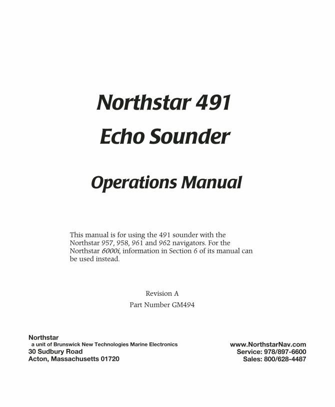
Contents
1 Welcome
. . . . . . . . . . . . . . . . . . . . . . . . . . . . . . . . . . . 1
Welcome to the Northstar 491
. . . . . . . . . . . . 2
Using this manual
. . . . . . . . . . . . . . . . . . . . . . 2
Technical support
. . . . . . . . . . . . . . . . . . . . . . 4
How echo sounding works
. . . . . . . . . . . . . . . 5
Powering the 491 on and off
. . . . . . . . . . . . . 7
Setting up the 491
. . . . . . . . . . . . . . . . . . . . . 7
2 Quick Start: Using the Echo Sounder
. . . . . . . . . 11
Displaying the echo sounder’s picture
. . . . . 12
Using demo mode
. . . . . . . . . . . . . . . . . . . . . 14
Introducing the displayed information
. . . . 15
Using automatic mode
. . . . . . . . . . . . . . . . . 16
Changing the frequency of echoes
. . . . . . . 17
Zooming in and out
. . . . . . . . . . . . . . . . . . . 19
Setup functions
. . . . . . . . . . . . . . . . . . . . . . . 22
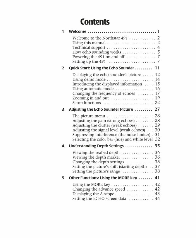
3 Adjusting the Echo Sounder Picture
. . . . . . . . . 27
The picture menu
. . . . . . . . . . . . . . . . . . . . . 28
Adjusting the gain (strong echoes)
. . . . . . . . 28
Adjusting the clutter (weak echoes)
. . . . . . . 29
Adjusting the signal level (weak echoes)
. . . 30
Suppressing interference (the noise limiter)
. 31
Selecting the color bar (hue) and white level
32
4 Understanding Depth Settings
. . . . . . . . . . . . . . 35
Viewing the seabed depth
. . . . . . . . . . . . . . 36
Viewing the depth marker
. . . . . . . . . . . . . . 36
Changing the depth settings
. . . . . . . . . . . . 36
Setting the picture’s shift (starting depth)
. . 37
Setting the picture’s range
. . . . . . . . . . . . . . 38
5 Other Functions: Using the MORE key
. . . . . . . 41
Using the MORE key
. . . . . . . . . . . . . . . . . . . 42
Changing the advance speed
. . . . . . . . . . . . 42
Displaying the A-scope
. . . . . . . . . . . . . . . . . 43
Setting the ECHO screen data
. . . . . . . . . . . 44
Introducing snapshots
. . . . . . . . . . . . . . . . . 46
Setting up the video image overlay
. . . . . . . 49
6 Reviewing past echoes using SoundTrac
. . . . . 51
Viewing past echoes using SoundTrac
. . . . . 52
Marking fish as waypoints
. . . . . . . . . . . . . . 53
Navigating to a past echo position
. . . . . . . . 53
7 Setting the Alarms
. . . . . . . . . . . . . . . . . . . . . . . . . 55
Understanding the alarms
. . . . . . . . . . . . . . 56
Setting the fish alarm
. . . . . . . . . . . . . . . . . . 56
Setting the bottom alarm
. . . . . . . . . . . . . . . 58
Setting the temperature alarm
. . . . . . . . . . . 60
8 Troubleshooting 491 Operations
. . . . . . . . . . . . 63
Troubleshooting the echo sounder
. . . . . . . 64
Checking the transducer
. . . . . . . . . . . . . . . 65

491 Echo Sounder Operations Manual Page 1
1
Welcome
Welcome to the Northstar 491 . . . . . . . . . . . . . 1-2
Using this manual . . . . . . . . . . . . . . . . . . . . . . . . . 1-2
Technical support . . . . . . . . . . . . . . . . . . . . . . . . . 1-4
How echo sounding works . . . . . . . . . . . . . . . . . 1-5
Powering the 491 on and off . . . . . . . . . . . . . . 1-7
Setting up the 491 . . . . . . . . . . . . . . . . . . . . . . . . . 1-7
T
his chapter introduces the
Northstar 491 Operations Manual
, explains how to contact Northstar for technical support and service, and describes the 491’s basic set-up and power on/off procedures.
Page
2
491 Echo Sounder Operations Manual
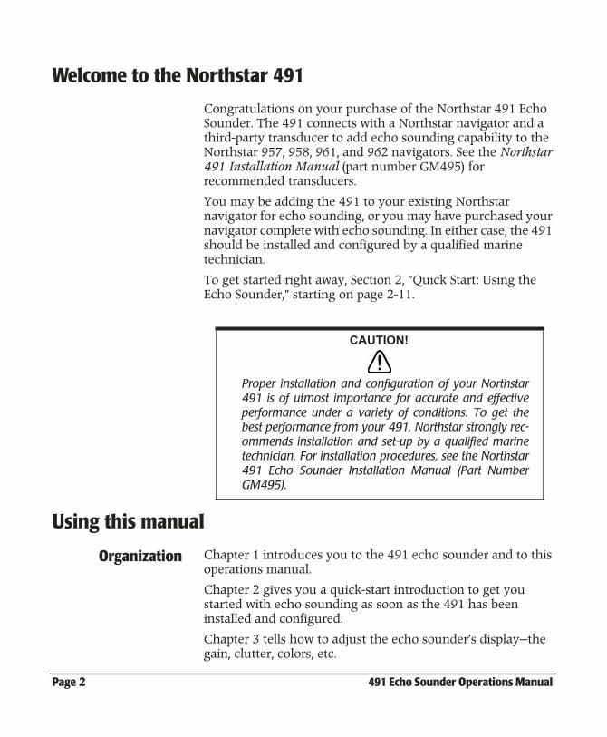
Welcome to the Northstar 491
Congratulations on your purchase of the Northstar 491 Echo Sounder. The 491 connects with a Northstar navigator and a third-party transducer to add echo sounding capability to the Northstar 957, 958, 961, and 962 navigators. See the
Northstar 491 Installation Manual
(part number GM495) for recommended transducers.
You may be adding the 491 to your existing Northstar navigator for echo sounding, or you may have purchased your navigator complete with echo sounding. In either case, the 491 should be installed and configured by a qualified marine technician.
To get started right away, Section 2, ”Quick Start: Using the Echo Sounder,” starting on page 2-11.
Using this manual
Organization
Chapter 1 introduces you to the 491 echo sounder and to this operations manual.
Chapter 2 gives you a quick-start introduction to get you started with echo sounding as soon as the 491 has been installed and configured.
Chapter 3 tells how to adjust the echo sounder’s display—the gain, clutter, colors, etc.
CAUTION!
Proper installation and configuration of your Northstar491 is of utmost importance for accurate and effectiveperformance under a variety of conditions. To get thebest performance from your 491, Northstar strongly rec-ommends installation and set-up by a qualified marinetechnician. For installation procedures, see the Northstar491 Echo Sounder Installation Manual (Part NumberGM495).
491 Echo Sounder Operations Manual Page 3
Chapter 4 describes how to adjust the depth settings to choose what portion of the water under the vessel you’ll display.
Chapter 5 explains other functions—the A-Scope, etc.
Chapter 6 describes Northstar’s exclusive SoundTrac™ feature, for accessing past echoes and navigating back to their locations.
Chapter 7 tells how to use the echo sounder’s alarms: the fish alarm, bottom alarm, and temperature alarm.
At the back of the manual are a glossary and an appendix outlining the 491’s specifications.
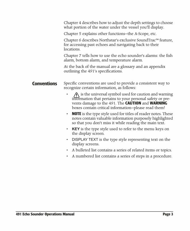
Conventions
Specific conventions are used to provide a consistent way to recognize certain information, as follows:
• is the universal symbol used for caution and warning information that pertains to your personal safety or pre-vents damage to the 491. The
CAUTION
and
WARNING
boxes contain critical information—please read them!
•
NOTE
is the type style used for titles of reader notes. These notes contain valuable information purposely highlighted so that you don’t miss it while reading the main text.
•
KEY
is the type style used to refer to the menu keys on the display screen.
•
DISPLAY TEXT
is the type style representing text on the display screens.
• A bulleted list contains a series of related items or topics.
• A numbered list contains a series of steps in a procedure.
Page
4
491 Echo Sounder Operations Manual
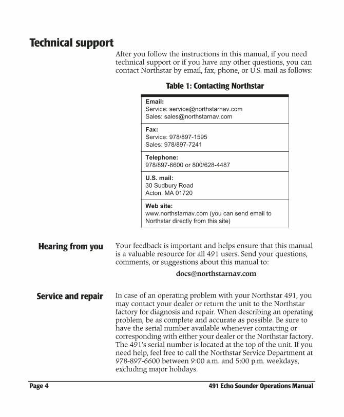
Technical support
After you follow the instructions in this manual, if you need technical support or if you have any other questions, you can contact Northstar by email, fax, phone, or U.S. mail as follows:
Hearing from you
Your feedback is important and helps ensure that this manual is a valuable resource for all 491 users. Send your questions, comments, or suggestions about this manual to:
Service and repair
In case of an operating problem with your Northstar 491, you may contact your dealer or return the unit to the Northstar factory for diagnosis and repair. When describing an operating problem, be as complete and accurate as possible. Be sure to have the serial number available whenever contacting or corresponding with either your dealer or the Northstar factory. The 491’s serial number is located at the top of the unit. If you need help, feel free to call the Northstar Service Department at 978-897-6600 between 9:00 a.m. and 5:00 p.m. weekdays, excluding major holidays.
Table 1: Contacting Northstar
:
Service: [email protected]: [email protected]
Fax
:
Service: 978/897-1595Sales: 978/897-7241
Telephone:
978/897-6600 or 800/628-4487
U.S. mail:
30 Sudbury RoadActon, MA 01720
Web site:
www.northstarnav.com (you can send email to Northstar directly from this site)
491 Echo Sounder Operations Manual Page 5
To prevent delays, it is critical that you first obtain a Return Materials Authorization (RMA) number before returning your unit to the factory. If you purchased your 491 through a dealer, to get an RMA number, call the dealer with the serial number. The 491’s serial number is located at the top of the unit.
The 491 should be shipped in a properly designed carton with packing material. Please reference the RMA number on the outside of the carton.
Shipments to Northstar should be made to the following address:
Northstar Technologies30 Sudbury RoadActon, MA 01720
If you have overnight or second-day shipping requirements, please call the Northstar factory for turnaround time and freight costs before shipping your 491.
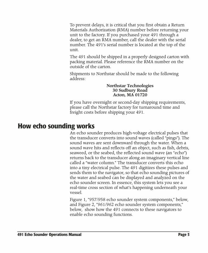
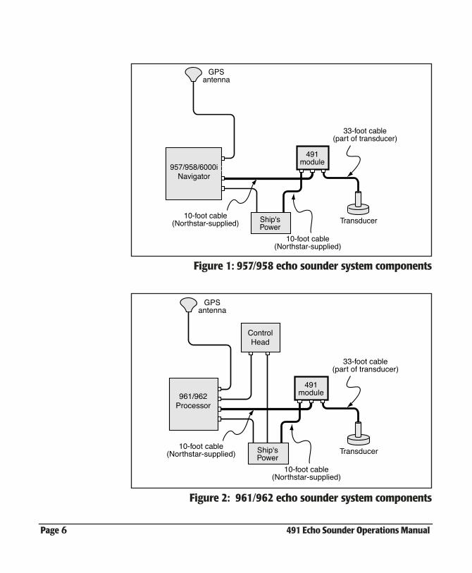
How echo sounding works
An echo sounder produces high-voltage electrical pulses that the transducer converts into sound waves (called “pings”). The sound waves are sent downward through the water. When a sound wave hits and reflects off an object, such as fish, debris, seaweed, or the seabed, the reflected sound wave (an “echo”) returns back to the transducer along an imaginary vertical line called a “water column.” The transducer converts this echo into a tiny electrical pulse. The 491 digitizes these pulses and sends them to the navigator, so that echo sounding pictures of the water and seabed can be displayed and analyzed on the echo sounder screen. In essence, this system lets you see a real-time cross section of what’s happening underneath your vessel.
Figure 1, ”957/958 echo sounder system components,” below, and Figure 2, ”961/962 echo sounder system components,” below, show how the 491 connects to these navigators to enable echo sounding functions.
Page
6
491 Echo Sounder Operations Manual
Figure 1: 957/958 echo sounder system components
Figure 2: 961/962 echo sounder system components
957/958/6000iNavigator
491module
GPSantenna
TransducerShip'sPower
10-foot cable(Northstar-supplied)
10-foot cable(Northstar-supplied)
33-foot cable(part of transducer)
961/962Processor
ControlHead
491module
GPSantenna
TransducerShip'sPower
10-foot cable(Northstar-supplied)
10-foot cable(Northstar-supplied)
33-foot cable(part of transducer)
491 Echo Sounder Operations Manual Page 7
Powering the 491 on and off
As part of its power-up sequence, the navigator automatically activates the 491.
The 491 is automatically shut off by the navigator when you press and hold
PWR
until the screen goes dark.
Setting up the 491Your 491 should be installed by a qualified marine technician. Your satisfaction with the system’s performance will be greatly influenced by the practical knowledge and experience of the installer. Unlike GPS or other marine electronics systems, echo sounder installation is as much an art as a science.
The installation procedure includes setting up the following options:
• the transducer’s depth
• the speed and temperature
• the calibration for the speed sensor
• the calibration for the temperature sensor
• the gain calibration for the transducer
You may wish to change the following options from time to time to match your personal preferences:
• depth units (feet, meters, or fathoms) on the screen
• temperature units (Celsius or Fahrenheit) on the screen
• temperature scale (lowest and highest) on the screen
• (961/962 only) automatic saving of *FISH##* or *THERM##* waypoints when the 491 detects the presence of fish or a certain water temperature that you’ve set
Using 491 with the961/962
Before starting, you should double-check that the 961/962’s Port 3 is set to the 490 option:
1. Press STAR until you reach the SERVICE MENU screen.
2. Press PORT SETUP.
3. Press PORT 3.
Page 8 491 Echo Sounder Operations Manual
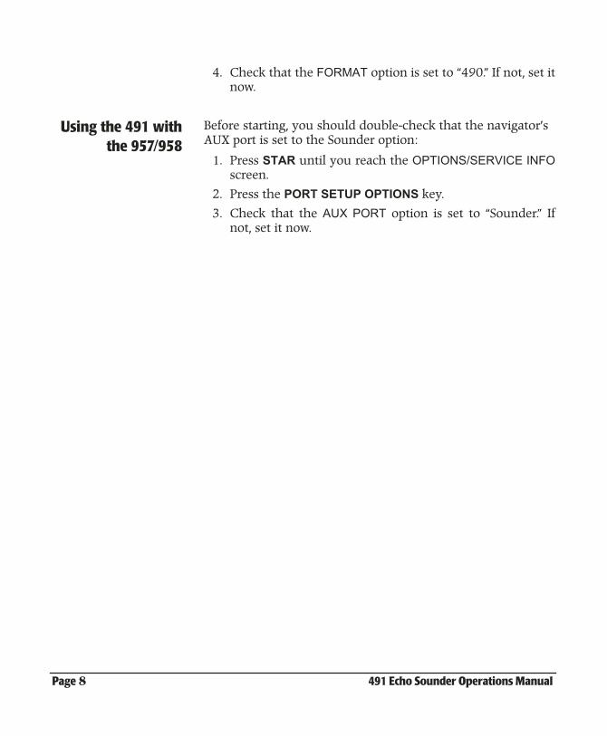
4. Check that the FORMAT option is set to “490.” If not, set itnow.
Using the 491 withthe 957/958
Before starting, you should double-check that the navigator’s AUX port is set to the Sounder option:
1. Press STAR until you reach the OPTIONS/SERVICE INFOscreen.
2. Press the PORT SETUP OPTIONS key.
3. Check that the AUX PORT option is set to “Sounder.” Ifnot, set it now.
491 Echo Sounder Operations Manual Page 9
Figure 3:
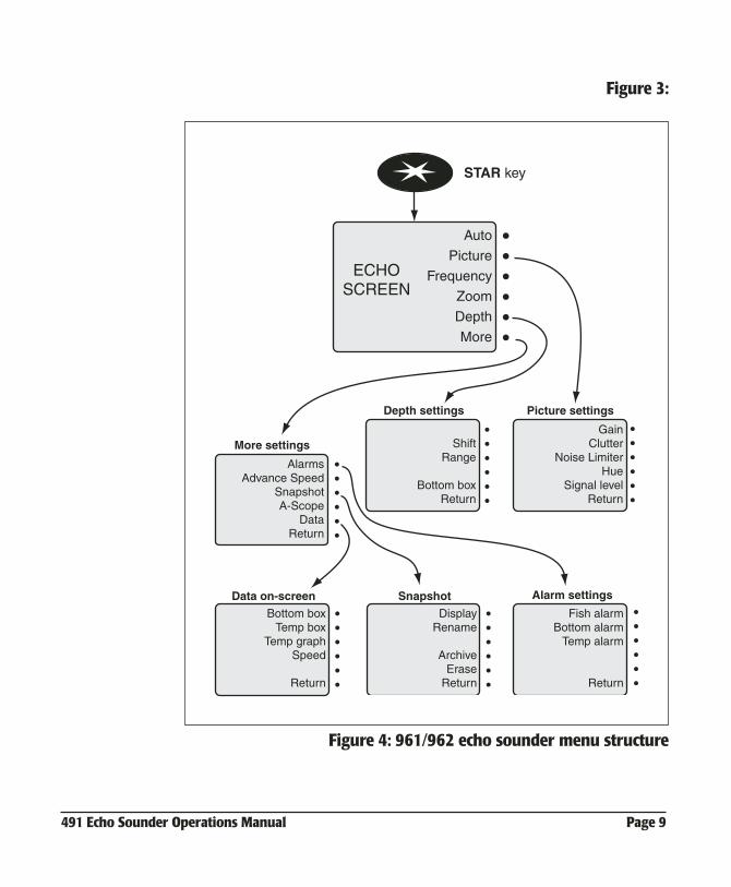
Figure 4: 961/962 echo sounder menu structure
STAR key
Auto
Picture
Frequency
Zoom
Depth
More
ECHOSCREEN
GainClutter
Noise LimiterHue
Signal levelReturn
ShiftRange
Bottom boxReturn
AlarmsAdvance Speed
SnapshotA-Scope
DataReturn
Fish alarmBottom alarm
Temp alarm
Return
Bottom boxTemp box
Temp graphSpeed
Return
Picture settingsDepth settings
More settings
Alarm settingsData on-screen
DisplayRename
ArchiveErase
Return
Snapshot
Page 10 491 Echo Sounder Operations Manual
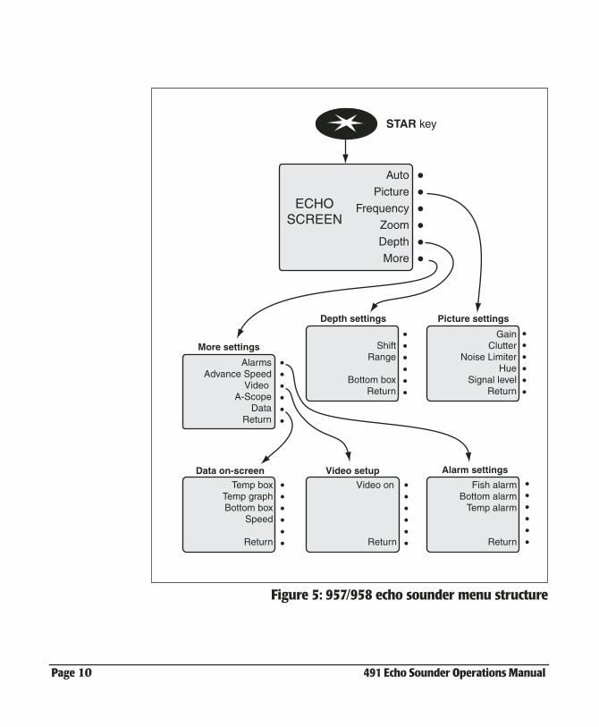
Figure 5: 957/958 echo sounder menu structure
STAR key
Auto
Picture
Frequency
Zoom
Depth
More
ECHOSCREEN
GainClutter
Noise LimiterHue
Signal levelReturn
ShiftRange
Bottom boxReturn
AlarmsAdvance Speed
Video A-Scope
DataReturn
Fish alarmBottom alarm
Temp alarm
Return
Temp boxTemp graphBottom box
Speed
Return
Picture settingsDepth settings
More settings
Alarm settingsData on-screen
Video on
Return
Video setup
491 Echo Sounder Operations Manual Page 11
2Quick Start: Using the Echo Sounder
Displaying the echo sounder’s picture . . . . 2-12
Using demo mode . . . . . . . . . . . . . . . . . . . . . . . . 2-14
Introducing the displayed information . . . . 2-15
Using automatic mode . . . . . . . . . . . . . . . . . . . . 2-16
Changing the frequency of echoes . . . . . . . . 2-17
Zooming in and out . . . . . . . . . . . . . . . . . . . . . . . 2-19
Setup functions . . . . . . . . . . . . . . . . . . . . . . . . . . . 2-22
This chapter shows you how to start using the echo sounder, and explains several of the echo sounder’s important features.
Page 12 491 Echo Sounder Operations Manual
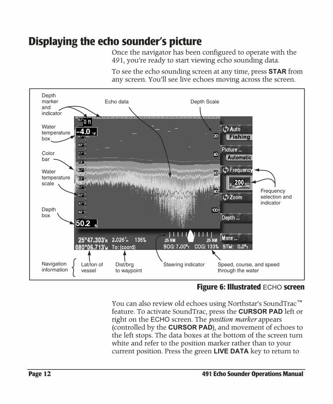
Displaying the echo sounder’s pictureOnce the navigator has been configured to operate with the 491, you’re ready to start viewing echo sounding data.
To see the echo sounding screen at any time, press STAR from any screen. You’ll see live echoes moving across the screen.
Figure 6: Illustrated ECHO screen
You can also review old echoes using Northstar’s SoundTrac™ feature. To activate SoundTrac, press the CURSOR PAD left or right on the ECHO screen. The position marker appears (controlled by the CURSOR PAD), and movement of echoes to the left stops. The data boxes at the bottom of the screen turn white and refer to the position marker rather than to your current position. Press the green LIVE DATA key to return to
Depth Scale
Depthbox
Watertemperaturebox
Watertemperaturescale
Depthmarkerandindicator
Echo data
Lat/lon ofvessel
Dist/brgto waypoint
Steering indicator Speed, course, and speedthrough the water
Frequencyselection andindicator
Navigationinformation
Colorbar
491 Echo Sounder Operations Manual Page 13
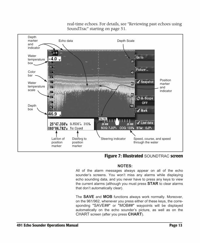
real-time echoes. For details, see “Reviewing past echoes using SoundTrac” starting on page 51.
Figure 7: Illustrated SOUNDTRAC screen
NOTES:All of the alarm messages always appear on all of the echosounder’s screens. You won’t miss any alarms while displayingecho sounding data, and you never have to press any keys to viewthe current alarms (although you must press STAR to clear alarmsthat don’t automatically clear).
The SAVE and MOB functions always work normally. Moreover,on the 961/962, whenever you press either of these keys, the corre-sponding *SAVE##* or *MOB##* waypoints will be displayedautomatically on the echo sounder’s picture, as well as on theCHART screen (after you press CHART).
Depth Scale
Depthbox
Watertemperaturebox
Watertemperaturescale
Depthmarkerandindicator
Echo data
Lat/lon ofpositionmarker
Dist/brg to positionmarker
Steering indicator Speed, course, and speedthrough the water
Colorbar
Positionmarkerandindicator
Page 14 491 Echo Sounder Operations Manual
Using demo modeThe echo sounder can be operated in “demo mode” for training and familiarization. Simulated echo data generated by the 491 will be displayed.
To enter demo mode:
1. Press STAR several times to display the ECHO SOUNDERSETUP screen.
2. Press the CURSOR PAD down to select demo mode, then press EDIT.
3. Press the CURSOR PAD left or right to highlight “ON,” then press ACCEPT.
While in demo mode, the word “Demo” appears in theupper right corner of the ECHO screen.
To leave demo mode, repeat this procedure, selecting “OFF” instead of “ON.”
Displaying echosounder data on the
CHART screen
You can overlay a smaller version of the echo screen onto the CHART screen.
For the 961/962 To overlay the echo screen:
1. Press CHART to display the CHART screen, then pressOVERLAY.
2. At the CHART OVERLAY SELECTION window, press SHOW 490.
Both chart views A and B will display live echo sounderdata on the right-hand side of the screen.
3. To remove echo sounder data, press HIDE 490 on the CHART OVERLAY screen.
For the 957/958 To overlay the echo screen:
1. Press CHART to display the CHART screen, then pressSOUNDER. The CHART screen will display live echosounder data on the right-hand side of the screen.
491 Echo Sounder Operations Manual Page 15
Introducing the displayed information The following information can be displayed on the ECHO screen.
Echo sounding • echo sounder data
• echo sounder frequency in use (50 or 200 kHz or both)
• A-scope
• automatic mode indicators (fishing or cruising)
• manual operation indicator
• echo colors in use (the “color bar” at the far left)
• SoundTrac’s position marker for scrolling to old echoes
Depth andtemperature
• water-depth digital display (on the left side of the screen)
• depth scale (on the right side)
• depth marker (press the CURSOR PAD to scroll the marker down)
• water-temperature digital display (if temperature sensor is connected; can be turned off)
• water temperature graph (if temperature sensor is con-nected; can be turned off)
Navigation • vessel’s current lat/lon (on the SOUNDTRAC screen, this lat/lon indicates the position marker’s location)
• vessel’s SOG and COG
• active waypoint, if any, and graphic steering indicator
• vessel’s Speed Through the Water (if speed sensor is con-nected; can be turned off)
Status tabs To help you use the echo sounder’s functions, many of the key’s labels on the right edge of the screen show the status of that key’s function in a tab directly under the label.
Page 16 491 Echo Sounder Operations Manual
Using automatic mode To operate the echo sounder automatically, just press AUTO. All of the 491’s adjustments will be set to produce a useful picture under most conditions. When you’re too busy to optimize the settings manually, the echo sounder can automatically set the optimal gain, clutter, and range settings, to show an excellent picture, from the surface to the bottom.
When you select auto, the range setting may change from time totime to keep the seabed in view as the water depth changes.
It is recommended that the 491 be operated automatically whenever possible. The 491 can reliably detect the seabed depth only when it controls the gain and clutter settings.
You can always press AUTO on the ECHO screen to remove any manual settings you’ve made and return to the standard automatic configuration.
Cruising or fishing Automatic mode has two variations: autocruising and autofishing.
• autocruising optimizes the gain and clutter for tracking the bottom, with less emphasis on any fish in the water
• autofishing optimizes the gain and clutter for searching for fish
Press AUTO to switch between autocruising and autofishing. The colored tab below the menu key indicates whether the unit is optimized for cruising or fishing.
The status tabs Colored status tabs just below the AUTO and PICTURE keys are green when the echo sounder is operating fully automatically. They turn yellow when any of the settings has been set manually. (In some cases, the picture tab may be yellow while the auto tab is still green, if the Noise Limiter is turned on, for example.)
491 Echo Sounder Operations Manual Page 17
Manuallyoverriding
automatic mode
You can always manually change any of the echo sounder’s settings: the gain, clutter, noise limiter, shift, and range.
Changing the appearance of the picture (colors, gain, clutter, and the noise limiter) is described in Chapter 3.
Setting the range and shift is described in Chapter 6.
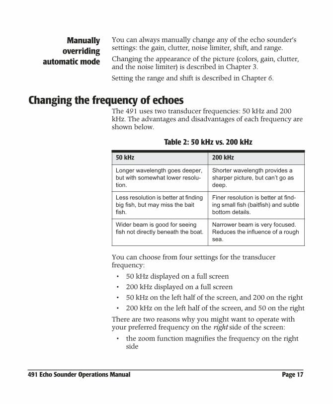
Changing the frequency of echoesThe 491 uses two transducer frequencies: 50 kHz and 200 kHz. The advantages and disadvantages of each frequency are shown below.
You can choose from four settings for the transducer frequency:
• 50 kHz displayed on a full screen
• 200 kHz displayed on a full screen
• 50 kHz on the left half of the screen, and 200 on the right
• 200 kHz on the left half of the screen, and 50 on the right
There are two reasons why you might want to operate with your preferred frequency on the right side of the screen:
• the zoom function magnifies the frequency on the right side
Table 2: 50 kHz vs. 200 kHz
50 kHz 200 kHz
Longer wavelength goes deeper, but with somewhat lower resolu-tion.
Shorter wavelength provides a sharper picture, but can’t go as deep.
Less resolution is better at finding big fish, but may miss the bait fish.
Finer resolution is better at find-ing small fish (baitfish) and subtle bottom details.
Wider beam is good for seeing fish not directly beneath the boat.
Narrower beam is very focused. Reduces the influence of a rough sea.
Page 18 491 Echo Sounder Operations Manual
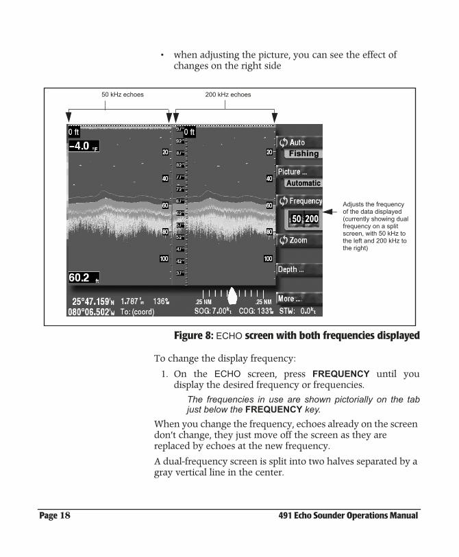
• when adjusting the picture, you can see the effect of changes on the right side
Figure 8: ECHO screen with both frequencies displayed
To change the display frequency:
1. On the ECHO screen, press FREQUENCY until youdisplay the desired frequency or frequencies.
The frequencies in use are shown pictorially on the tabjust below the FREQUENCY key.
When you change the frequency, echoes already on the screen don’t change, they just move off the screen as they are replaced by echoes at the new frequency.
A dual-frequency screen is split into two halves separated by a gray vertical line in the center.
Adjusts the frequency of the data displayed (currently showing dual frequency on a split screen, with 50 kHz to the left and 200 kHz to the right)
50 kHz echoes 200 kHz echoes
491 Echo Sounder Operations Manual Page 19
When using the zoom feature (which also splits the screen into halves), both sides of the screen always display the same frequency.
Zooming in and out On the ECHO screen, the echo sounder’s zoom feature expands a portion of the echoes. You can examine closely any part of the water column, to determine the composition of the bottom or look at the echoes of fish, rocks, or wrecks. When fishing, the zoom function is useful for showing a detailed view of any echoes below the vessel.
Choosing the zoomscale
Press IN to zoom in and increase the magnification of the echoes you see below the top edge of the marker. Press OUT to zoom out and increase the amount of water seen.
You can choose from any of six depth scales for the magnified echoes. These scales cover the same depths regardless of the scale of the original echoes.
The available scales are: 15’, 30’, 60’, 120’, 240’ and 480’ when using units of “feet.” Similar scales are available for the other depth units.
NOTE:When zoom is in use, only a single frequency is displayed.Unzoomed echoes are on the right, and the same frequency isshown magnified on the left. Whatever frequency was previouslyshown on the left is replaced by a magnified view of the right side.
NOTE:You cannot zoom out to a scale that shows more water than theoriginal picture. For example, if the original picture is set to a scaleof 50’, the only zoom scales available will be 15’ and 30’.
Choosing a zoommode
Press ZOOM on the ECHO screen to cycle through the four zoom modes (and choose the one you want):
• bottom zoom
• bottom lock
• bottom lock/center
Page 20 491 Echo Sounder Operations Manual
• marker zoom
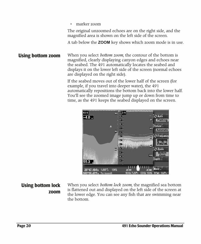
The original unzoomed echoes are on the right side, and the magnified area is shown on the left side of the screen.
A tab below the ZOOM key shows which zoom mode is in use.
Using bottom zoom When you select bottom zoom, the contour of the bottom is magnified, clearly displaying canyon edges and echoes near the seabed. The 491 automatically locates the seabed and displays it on the lower left side of the screen (normal echoes are displayed on the right side).
If the seabed moves out of the lower half of the screen (for example, if you travel into deeper water), the 491 automatically repositions the bottom back into the lower half. You’ll see the zoomed image jump up or down from time to time, as the 491 keeps the seabed displayed on the screen.
Using bottom lockzoom
When you select bottom lock zoom, the magnified sea bottom is flattened out and displayed on the left side of the screen at the lower edge. You can see any fish that are swimming near the bottom.
491 Echo Sounder Operations Manual Page 21
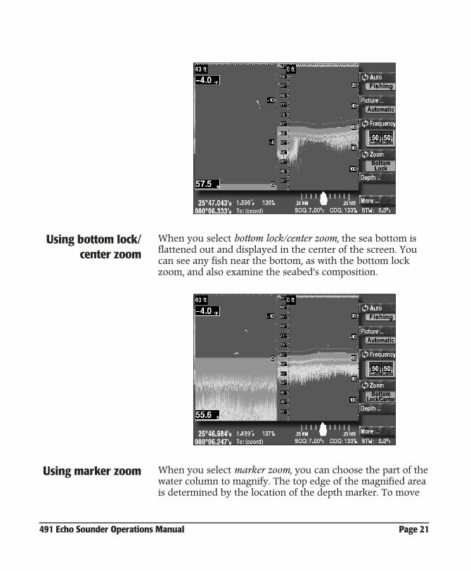
Using bottom lock/center zoom
When you select bottom lock/center zoom, the sea bottom is flattened out and displayed in the center of the screen. You can see any fish near the bottom, as with the bottom lock zoom, and also examine the seabed’s composition.
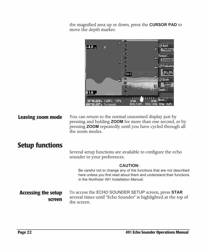
Using marker zoom When you select marker zoom, you can choose the part of the water column to magnify. The top edge of the magnified area is determined by the location of the depth marker. To move
Page 22 491 Echo Sounder Operations Manual
the magnified area up or down, press the CURSOR PAD to move the depth marker.
Leaving zoom mode You can return to the normal unzoomed display just by pressing and holding ZOOM for more than one second, or by pressing ZOOM repeatedly until you have cycled through all the zoom modes.
Setup functionsSeveral setup functions are available to configure the echo sounder to your preferences.
CAUTION:Be careful not to change any of the functions that are not describedhere unless you first read about them and understand their functionsin the Northstar 491 Installation Manual.
Accessing the setupscreen
To access the ECHO SOUNDER SETUP screen, press STAR several times until “Echo Sounder” is highlighted at the top of the screen.
491 Echo Sounder Operations Manual Page 23
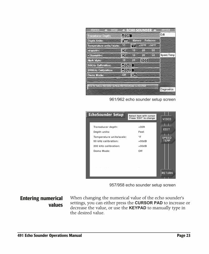
961/962 echo sounder setup screen
957/958 echo sounder setup screen
Entering numericalvalues
When changing the numerical value of the echo sounder’s settings, you can either press the CURSOR PAD to increase or decrease the value, or use the KEYPAD to manually type in the desired value.
Page 24 491 Echo Sounder Operations Manual
Transducer depth This option specifies how far below the surface of the water the transducer is mounted. The number is added to all depths measured by the 491 so they will refer to depth from the surface, not from the transducer. This value should have been set correctly during installation and should not be changed.
Changing the depthunits
You can change the depth units to feet, meters, or fathoms:
1. Press the CURSOR PAD up or down to highlight theDEPTH UNITS option.
2. Press EDIT.
3. Press the CURSOR PAD left or right to highlight the desired units. Press ACCEPT.
Changing thetemperature
graph’s units andscale
You can change the highest and lowest water temperatures that will be displayed on the temperature graph:
1. Press the CURSOR PAD up or down to highlight the linecontaining the temperature scale.
2. Press EDIT.
3. Press the CURSOR PAD left or right to highlight °C or °F, as desired, then press ACCEPT.
4. To change the endpoints of the scale, press EDIT DATA.
5. Enter the lower temperature limit using the KEYPAD.
6. Press the CURSOR PAD to the right to highlight the upper limit and enter its value on the KEYPAD.
7. Press ACCEPT.
Number of specialwaypoints
In the 961/962, the echo sounder can be set to store waypoints automatically at the following location:
• where fish are detected by the fish alarm
• where the water temperature passes preset limits
• where fish or other echoes are marked by the user
These waypoints are automatically given names such as *FISH##*, where ## is a waypoint sequence number that increases to a preset limit. When this limit is reached, the
This option only appears on the screen if a temperature sensor is connected.
491 Echo Sounder Operations Manual Page 25
sequence number restarts at 00, and the oldest waypoints with this same name will be overwritten (unless they have been renamed).
To turn this feature on or off, or to change the maximum number of each of these waypoints:
1. Press the CURSOR PAD up or down to highlight thewaypoint type you want to change:The line “*Fish##*:” controls fish waypointsThe line “*Therm##*:” controls temperature waypointsThe line “Mark Wpts:” controls waypoints marked by the user
2. Press EDIT.
3. Press the CURSOR PAD left or right to highlight the desired number of waypoints to be saved.
4. Press ACCEPT.
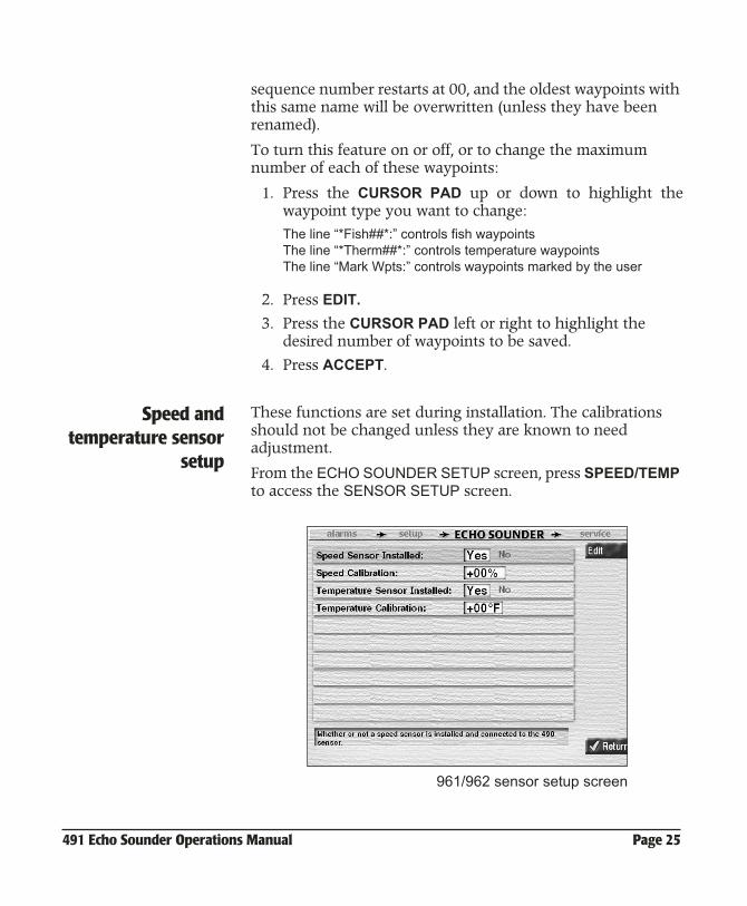
Speed andtemperature sensor
setup
These functions are set during installation. The calibrations should not be changed unless they are known to need adjustment.
From the ECHO SOUNDER SETUP screen, press SPEED/TEMP to access the SENSOR SETUP screen.
961/962 sensor setup screen
Page 26 491 Echo Sounder Operations Manual
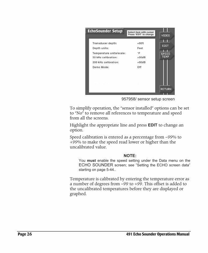
957958/ sensor setup screen
To simplify operation, the “sensor installed” options can be set to “No” to remove all references to temperature and speed from all the screens.
Highlight the appropriate line and press EDIT to change an option.
Speed calibration is entered as a percentage from –99% to +99% to make the speed read lower or higher than the uncalibrated value.
NOTE: You must enable the speed setting under the Data menu on theECHO SOUNDER screen; see ”Setting the ECHO screen data”starting on page 5-44..
Temperature is calibrated by entering the temperature error as a number of degrees from –99 to +99. This offset is added to the uncalibrated temperatures before they are displayed or graphed.
491 Echo Sounder Operations Manual Page 27
3Adjusting the Echo Sounder Picture
The picture menu . . . . . . . . . . . . . . . . . . . . . . . . 3-28
Adjusting the gain (strong echoes) . . . . . . . . 3-28
Adjusting the clutter (weak echoes) . . . . . . . 3-29
Adjusting the signal level (weak echoes) . . 3-30
Suppressing interference (the noise limiter) 3-31
Selecting the color bar (hue) and white level 3-32
This chapter explains the different ways you can adjust the echo sounder’s picture, including gain, clutter, the noise limiter, white level, and signal level.
Page 28 491 Echo Sounder Operations Manual
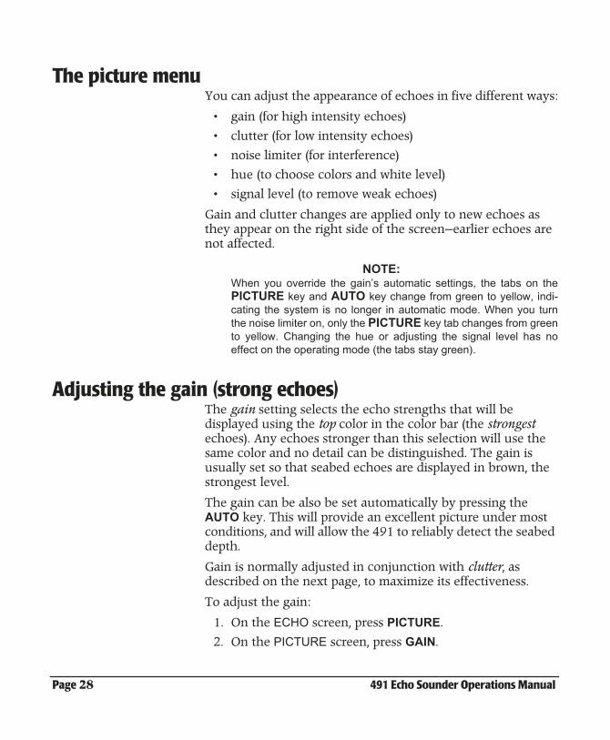
The picture menuYou can adjust the appearance of echoes in five different ways:
• gain (for high intensity echoes)
• clutter (for low intensity echoes)
• noise limiter (for interference)
• hue (to choose colors and white level)
• signal level (to remove weak echoes)
Gain and clutter changes are applied only to new echoes as they appear on the right side of the screen—earlier echoes are not affected.
NOTE:When you override the gain’s automatic settings, the tabs on thePICTURE key and AUTO key change from green to yellow, indi-cating the system is no longer in automatic mode. When you turnthe noise limiter on, only the PICTURE key tab changes from greento yellow. Changing the hue or adjusting the signal level has noeffect on the operating mode (the tabs stay green).
Adjusting the gain (strong echoes)The gain setting selects the echo strengths that will be displayed using the top color in the color bar (the strongest echoes). Any echoes stronger than this selection will use the same color and no detail can be distinguished. The gain is usually set so that seabed echoes are displayed in brown, the strongest level.
The gain can be also be set automatically by pressing the AUTO key. This will provide an excellent picture under most conditions, and will allow the 491 to reliably detect the seabed depth.
Gain is normally adjusted in conjunction with clutter, as described on the next page, to maximize its effectiveness.
To adjust the gain:
1. On the ECHO screen, press PICTURE.
2. On the PICTURE screen, press GAIN.
491 Echo Sounder Operations Manual Page 29
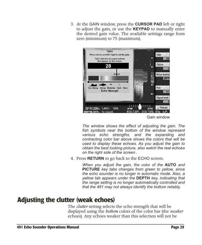
3. At the GAIN window, press the CURSOR PAD left or rightto adjust the gain, or use the KEYPAD to manually enterthe desired gain value. The available settings range fromzero (minimum) to 75 (maximum).
Gain window
The window shows the effect of adjusting the gain. Thefish symbols near the bottom of the window representvarious echo strengths, and the expanding andcontracting color bar above shows the colors that will beused to display these echoes. As you adjust the gain toobtain the best looking picture, also watch the real echoeson the right side of the screen .
4. Press RETURN to go back to the ECHO screen.
When you adjust the gain, the color of the AUTO andPICTURE key tabs changes from green to yellow, sincethe echo sounder is no longer in automatic mode. Also, ayellow tab appears under the DEPTH key, indicating thatthe range setting is no longer automatically controlled andthat the 491 may not always identify the bottom reliably.
Adjusting the clutter (weak echoes)The clutter setting selects the echo strength that will be displayed using the bottom colors of the color bar (the weaker echoes). Any echoes weaker than this selection will not be
Page 30 491 Echo Sounder Operations Manual
displayed. If you select 5, for example, all weak and moderate echoes will be displayed using the background color (just as if they weren’t there). You might choose this setting to eliminate high levels of background noise and echoes from turbulence or plankton. A setting of 0 allows all echoes to be displayed.
To adjust the clutter:
1. At the ECHO screen, press PICTURE.
2. At the PICTURE screen, press CLUTTER.
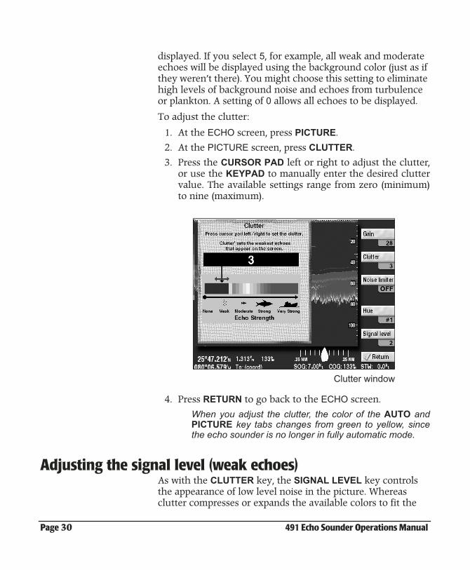
3. Press the CURSOR PAD left or right to adjust the clutter,or use the KEYPAD to manually enter the desired cluttervalue. The available settings range from zero (minimum)to nine (maximum).
Clutter window
4. Press RETURN to go back to the ECHO screen.
When you adjust the clutter, the color of the AUTO andPICTURE key tabs changes from green to yellow, sincethe echo sounder is no longer in fully automatic mode.
Adjusting the signal level (weak echoes)As with the CLUTTER key, the SIGNAL LEVEL key controls the appearance of low level noise in the picture. Whereas clutter compresses or expands the available colors to fit the
491 Echo Sounder Operations Manual Page 31
desired signal range, Signal Level completely removes the weaker colors and their echoes.
To adjust the signal level:
1. On the ECHO screen, press PICTURE.
2. On the PICTURE screen, press SIGNAL LEVEL.
3. At the SIGNAL LEVEL window, press the CURSOR PADup or down to remove the weaker color levels from thepicture, or use the KEYPAD to manually enter the desiredsignal level.
The available settings range from 1 (minimum) to 5 (max-imum). For example, if you select a signal level of 3, echo strengths of 0 through 3 are all displayed using the same color.
4. Press RETURN to go back to the ECHO screen.
Suppressing interference (the noise limiter)The noise limiter reduces the adverse effects of interference from other nearby echo sounders or electronic devices. however, the noise limiter may cause some very weak echoes to be made smaller or entirely eliminated, since it removes any echoes that aren’t sustained for at least two pings.
To turn on the noise limiter:
1. At the ECHO screen, press PICTURE.
2. At the PICTURE screen, press NOISE LIMITER.
3. At the NOISE LIMITER window, press the CURSOR PADup to turn the noise limiter on (or press NOISE LIMITERagain).
4. Press the RETURN key to go back to the ECHO screen.
Turning the noise limiter on changes a portion of thePICTURE key tab from green to yellow, as a reminder.
Page 32 491 Echo Sounder Operations Manual
Selecting the color bar (hue) and white level
Understanding thecolor bar
The color bar displayed at the extreme left of the ECHO screen shows the range of colors used to display different echo strengths. Weaker echoes are displayed with colors near the bottom of the scale, and stronger echoes are displayed with colors near the top.
You can choose any one of nine palettes of colors to represent the echo strengths from weakest to strongest.
• Color bar #1 is the one most often used.
• Color bar #2 is similar but with fewer colors, to aid visibil-ity under some conditions.
• Color bars # 3-8 are additional variations with different background colors.
• Color bar #9 uses only a single color, ranging from very dark to very bright.
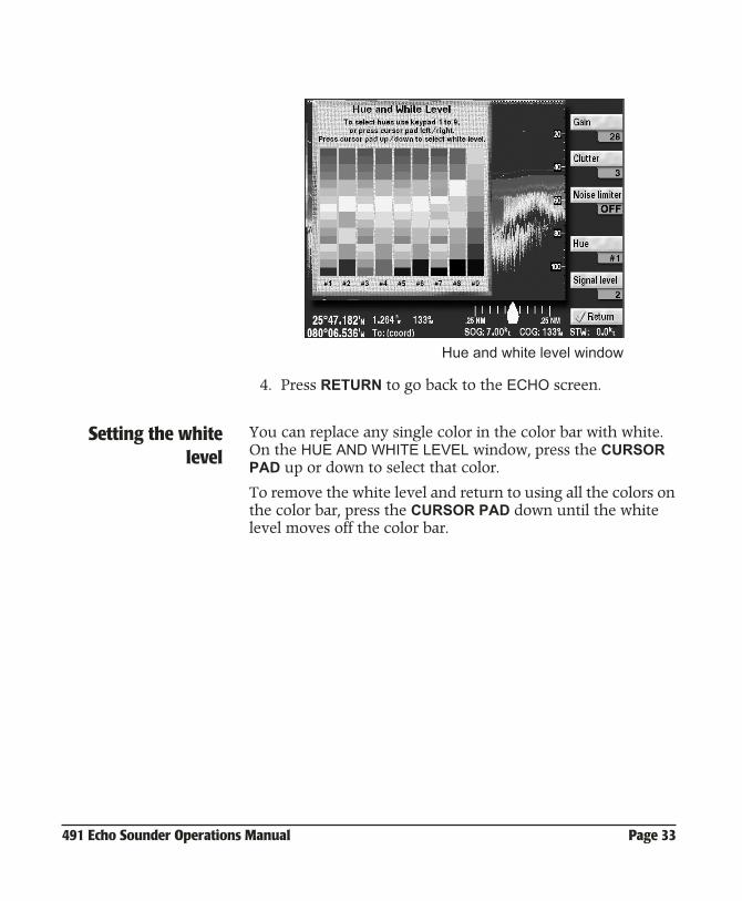
Selecting the colorbar (hue)
To select the color bar:
1. On the ECHO screen, press PICTURE.
2. Press HUE.
3. At the HUE AND WHITE LEVEL window, press theCURSOR PAD left or right to select the color bar desired,or use the KEYPAD to manually enter the number of thecolor bar.
491 Echo Sounder Operations Manual Page 33
Hue and white level window
4. Press RETURN to go back to the ECHO screen.
Setting the whitelevel
You can replace any single color in the color bar with white. On the HUE AND WHITE LEVEL window, press the CURSOR PAD up or down to select that color.
To remove the white level and return to using all the colors on the color bar, press the CURSOR PAD down until the white level moves off the color bar.

Page 34 491 Echo Sounder Operations Manual
491 Echo Sounder Operations Manual Page 35
4Understanding Depth Settings
Viewing the seabed depth . . . . . . . . . . . . . . . . 4-36
Viewing the depth marker . . . . . . . . . . . . . . . . 4-36
Changing the depth settings . . . . . . . . . . . . . . 4-36
Setting the picture’s shift (starting depth) . . 4-37
Setting the picture’s range . . . . . . . . . . . . . . . . 4-38
This chapter explains how to override the system’s auto-matic depth settings and manually control the depth range shown on the screen, and how to use the depth marker.
Page 36 491 Echo Sounder Operations Manual
Viewing the seabed depthThe seabed depth (the “bottom”) is displayed in a black box at the left edge of the ECHO screen.
You can change the size and location of the depth box on the ECHO screen. Its size on the SOUNDTRAC screen is always small.
There are four available sizes:
• small
• medium
• large
• huge
To resize the depth box or move it up or down:
1. At the ECHO screen, press DEPTH.
2. To cycle through the size choices, repeatedly pressBOTTOM BOX. To move the box up and down, press theCURSOR PAD.
3. Press RETURN to go back to the ECHO screen.
The depth box can also be adjusted by pressing MORE, then pressing DATA.
Viewing the depth marker You can use the depth marker to accurately measure the depth of an echo. To display the depth marker—a dashed horizontal line—and move this marker up or down, press the CURSOR PAD down. Attached to the depth marker line is a small black box, which displays the marker’s exact depth.
The depth marker also affects the display in Marker Zoom mode.
Changing the depth settingsYou can adjust the shallowest and deepest echoes to be shown on the ECHO screen. In automatic mode, the echo sounder sets these values based on its current environment. However,
491 Echo Sounder Operations Manual Page 37
you can manually override these auto values for your specific needs at any time. There are two depth settings:
• shift (how far below the surface the echo sounder picture starts)
• range (the depth covered by the echo sounder picture from the top of the screen to the bottom of the screen)
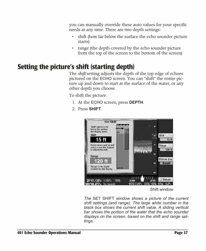
Setting the picture’s shift (starting depth) The shift setting adjusts the depth of the top edge of echoes pictured on the ECHO screen. You can “shift” the entire pic-ture up and down to start at the surface of the water, or any other depth you choose.
To shift the picture:
1. At the ECHO screen, press DEPTH.
2. Press SHIFT.
Shift window
The SET SHIFT window shows a picture of the currentshift settings (and range). The large white number in theblack box shows the current shift value. A sliding verticalbar shows the portion of the water that the echo sounderdisplays on the screen, based on the shift and range set-tings.
Page 38 491 Echo Sounder Operations Manual
In the large rectangle on the right, the blue area at the top(with waves) represents the surface of the water, and thebrown area below represents the seabed.
The number at the bottom is the depth of the picture, andthe seabed depth is also labelled.
The smaller rectangle inside the larger one represents theecho sounder’s picture. As you move the shift (and range)settings, this rectangle adjusts to show what you will seeon the echo screen.
A horizontal black arrow points to the value that this win-dow adjusts: the depth at which the echo sounder picturestarts, relative to the surface of the water.
3. Press the CURSOR PAD up or down to shift the picture,or use the KEYPAD to enter the digits of the desireddepth. If you type the number on the keypad, wait amoment for the system to enter the number.
4. Press RETURN to go back to the ECHO screen.
Adjusting shift changes the AUTO and DEPTH key tabsfrom green to yellow, since the echo sounder is no longerin automatic mode.
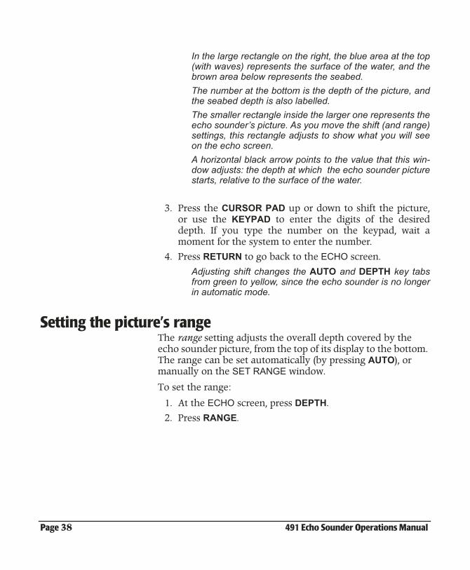
Setting the picture’s rangeThe range setting adjusts the overall depth covered by the echo sounder picture, from the top of its display to the bottom. The range can be set automatically (by pressing AUTO), or manually on the SET RANGE window.
To set the range:
1. At the ECHO screen, press DEPTH.
2. Press RANGE.
491 Echo Sounder Operations Manual Page 39
Range window
The vertical black arrow in the SET RANGE window ind-cates the values that this window adjusts: the range of theecho sounder picture, relative to the depth of the water.
The white number in the black box indicates the currentrange setting.
3. Press the CURSOR PAD up or down to adjust the range,or use the KEYPAD to manually enter the desired depth.
4. Press RETURN to go back to the ECHO screen.
Adjusting the range changes the AUTO and DEPTH sta-tus tab from green to yellow, since the echo sounder is nolonger in fully automatic mode.

Page 40 491 Echo Sounder Operations Manual
491 Echo Sounder Operations Manual Page 41
5Other Functions: Using the MORE key
Using the MORE key . . . . . . . . . . . . . . . . . . . . . . 5-42
Changing the advance speed . . . . . . . . . . . . . 5-42
Displaying the A-scope . . . . . . . . . . . . . . . . . . . 5-43
Setting the ECHO screen data . . . . . . . . . . . . . 5-44
Introducing snapshots . . . . . . . . . . . . . . . . . . . . 5-46
Setting up the video image overlay . . . . . . . 5-49
This chapter describes all of the functions of the MORE key, except for the alarms, which are covered in Chapter 7.
Page 42 491 Echo Sounder Operations Manual
Using the MORE keyPressing the MORE key accesses the following functions:
• alarms (described in Chapter 7)
• advance speed
• A-scope
• data (numeric and graphic information on the ECHO screen)
• snapshots (961/962 only)
• video overlay setup (957/958 only)
When the menu function is in use in the 961/962, the ECHO screen moves every half second, giving the picture a less than smooth appearance. Press RETURN to go back to the main screen for a normal smooth appearance.
Changing the advance speedAdvance speed refers to the speed at which the vertical scan lines move from right to left across the ECHO screen. There are five advance speeds (plus the STOP setting, which freezes the advance of all data):
• 2/1 - two identical lines of data are displayed for every ping
• 1/1 - one line of data is displayed for every ping
• 1/2 - one line of data is displayed for every two pings
• 1/4 - one line of data is displayed for every four pings
• 1/8 - one line of data is displayed for every eight pingsFor speeds 1/2, 1/4, and 1/8, each displayed line of data isaveraged over 2, 4, or 8 pings.
To set the advance speed:
1. At the ECHO screen, press MORE, then press ADVANCESPD.
2. At the SET ADVANCE SPEED window, keep pressing theADVANCE SPD key to select the desired advance speed.
3. Press RETURN to go back to the ECHO screen.
491 Echo Sounder Operations Manual Page 43
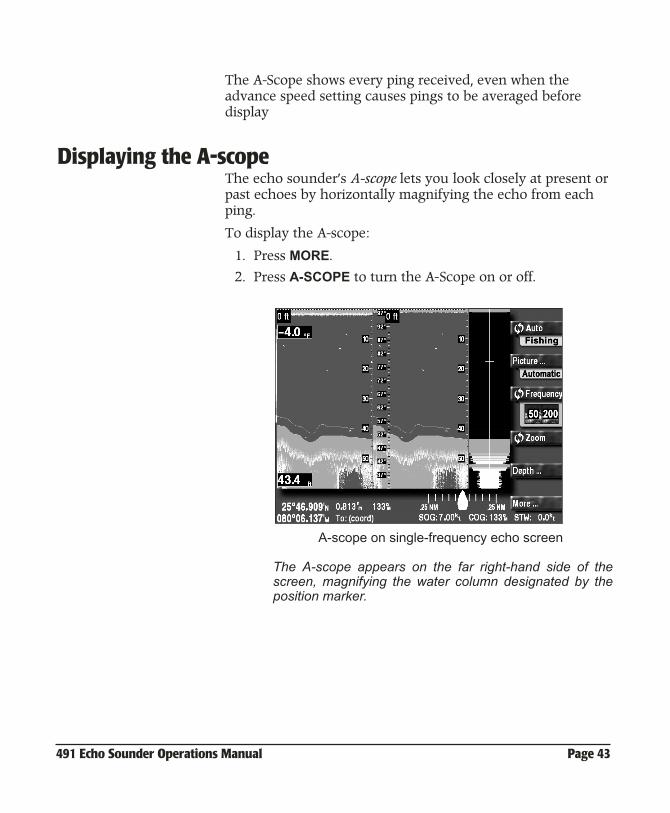
The A-Scope shows every ping received, even when the advance speed setting causes pings to be averaged before display
Displaying the A-scopeThe echo sounder’s A-scope lets you look closely at present or past echoes by horizontally magnifying the echo from each ping.
To display the A-scope:
1. Press MORE.
2. Press A-SCOPE to turn the A-Scope on or off.
A-scope on single-frequency echo screen
The A-scope appears on the far right-hand side of thescreen, magnifying the water column designated by theposition marker.
Page 44 491 Echo Sounder Operations Manual
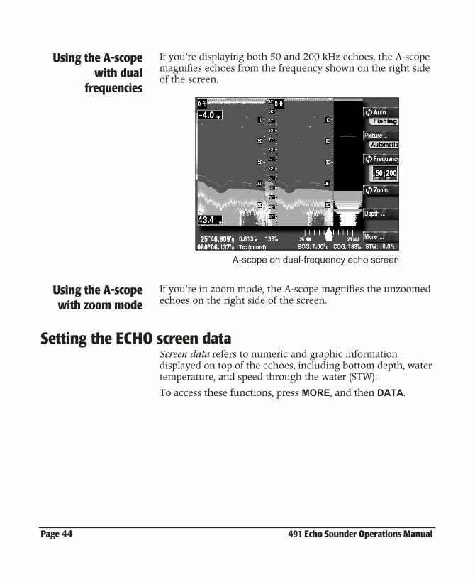
Using the A-scopewith dual
frequencies
If you’re displaying both 50 and 200 kHz echoes, the A-scope magnifies echoes from the frequency shown on the right side of the screen.
A-scope on dual-frequency echo screen
Using the A-scopewith zoom mode
If you’re in zoom mode, the A-scope magnifies the unzoomed echoes on the right side of the screen.
Setting the ECHO screen dataScreen data refers to numeric and graphic information displayed on top of the echoes, including bottom depth, water temperature, and speed through the water (STW).
To access these functions, press MORE, and then DATA.
491 Echo Sounder Operations Manual Page 45
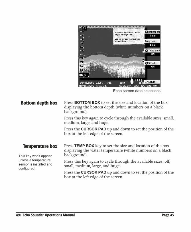
Echo screen data selections
Bottom depth box Press BOTTOM BOX to set the size and location of the box displaying the bottom depth (white numbers on a black background).
Press this key again to cycle through the available sizes: small, medium, large, and huge.
Press the CURSOR PAD up and down to set the position of the box at the left edge of the screen.
Temperature box Press TEMP BOX key to set the size and location of the box displaying the water temperature (white numbers on a black background).
Press this key again to cycle through the available sizes: off, small, medium, large, and huge.
Press the CURSOR PAD up and down to set the position of the box at the left edge of the screen.
This key won’t appear unless a temperature sensor is installed and configured.
Page 46 491 Echo Sounder Operations Manual
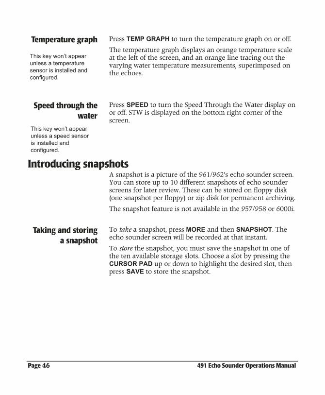
Temperature graph Press TEMP GRAPH to turn the temperature graph on or off.
The temperature graph displays an orange temperature scale at the left of the screen, and an orange line tracing out the varying water temperature measurements, superimposed on the echoes.
Speed through thewater
Press SPEED to turn the Speed Through the Water display on or off. STW is displayed on the bottom right corner of the screen.
Introducing snapshotsA snapshot is a picture of the 961/962’s echo sounder screen. You can store up to 10 different snapshots of echo sounder screens for later review. These can be stored on floppy disk (one snapshot per floppy) or zip disk for permanent archiving.
The snapshot feature is not available in the 957/958 or 6000i.
Taking and storinga snapshot
To take a snapshot, press MORE and then SNAPSHOT. The echo sounder screen will be recorded at that instant.
To store the snapshot, you must save the snapshot in one of the ten available storage slots. Choose a slot by pressing the CURSOR PAD up or down to highlight the desired slot, then press SAVE to store the snapshot.
This key won’t appear unless a temperature sensor is installed and configured.
This key won’t appear unless a speed sensor is installed and configured.
491 Echo Sounder Operations Manual Page 47
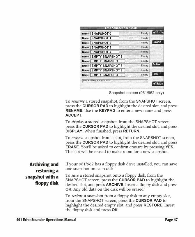
Snapshot screen (961/962 only)
To rename a stored snapshot, from the SNAPSHOT screen, press the CURSOR PAD to highlight the desired slot, and press RENAME. Use the KEYPAD to enter a new name and press ACCEPT.
To display a stored snapshot, from the SNAPSHOT screen, press the CURSOR PAD to highlight the desired slot, and press DISPLAY. When finished, press RETURN.
To erase a snapshot from a slot, from the SNAPSHOT screen, press the CURSOR PAD to highlight the desired slot, and press ERASE. You’ll be asked to confirm erasure by pressing YES. The slot will be erased to make room for a new snapshot.
Archiving andrestoring a
snapshot with afloppy disk
If your 961/962 has a floppy disk drive installed, you can save one snapshot on each disk.
To save a stored snapshot onto a floppy disk, from the SNAPSHOT screen, press the CURSOR PAD to highlight the desired slot, and press ARCHIVE. Insert a floppy disk and press OK. Any old data on the disk will be erased!
To restore a snapshot from a floppy disk to any empty slot, from the SNAPSHOT screen, press the CURSOR PAD to highlight the desired empty slot, and press RESTORE. Insert the floppy disk and press OK.
Page 48 491 Echo Sounder Operations Manual
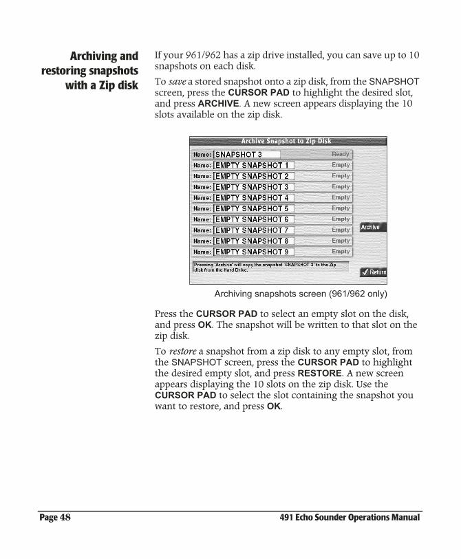
Archiving andrestoring snapshots
with a Zip disk
If your 961/962 has a zip drive installed, you can save up to 10 snapshots on each disk.
To save a stored snapshot onto a zip disk, from the SNAPSHOT screen, press the CURSOR PAD to highlight the desired slot, and press ARCHIVE. A new screen appears displaying the 10 slots available on the zip disk.
Archiving snapshots screen (961/962 only)
Press the CURSOR PAD to select an empty slot on the disk, and press OK. The snapshot will be written to that slot on the zip disk.
To restore a snapshot from a zip disk to any empty slot, from the SNAPSHOT screen, press the CURSOR PAD to highlight the desired empty slot, and press RESTORE. A new screen appears displaying the 10 slots on the zip disk. Use the CURSOR PAD to select the slot containing the snapshot you want to restore, and press OK.
491 Echo Sounder Operations Manual Page 49
Setting up the video image overlayIf you’ve connected the 957/958 to an NTSC-compatible device, you can display the image on the echo sounder screen.
To display the video image on the ECHO SOUNDER screen, first press MORE, then press VIDEO.
To change the transparency of the image while you’re displaying the ECHO SOUNDER screen, go to a different screen, press the navigator’s IN or OUT keys, then return to the ECHO SOUNDER screen.
To change the size and placement of the image on the ECHO SOUNDER screen, press the STAR key to display the navigator’s VIDEO SETUP screen, then follow the instructions on the screen.

Page 50 491 Echo Sounder Operations Manual
491 Echo Sounder Operations Manual Page 51
6Reviewing past echoes using SoundTrac
Viewing past echoes using SoundTrac . . . . 6-52
Marking fish as waypoints . . . . . . . . . . . . . . . . 6-53
Navigating to a past echo position . . . . . . . . 6-53
This chapter describes how to use SoundTrac to view past echoes, and how to navigate to any past echo positions.
Page 52 491 Echo Sounder Operations Manual
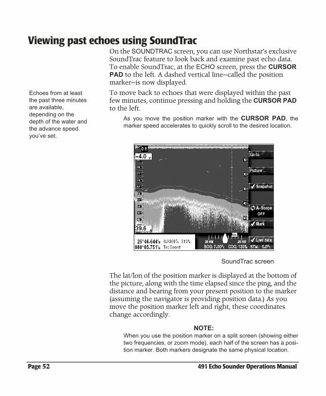
Viewing past echoes using SoundTracOn the SOUNDTRAC screen, you can use Northstar’s exclusive SoundTrac feature to look back and examine past echo data. To enable SoundTrac, at the ECHO screen, press the CURSOR PAD to the left. A dashed vertical line—called the position marker—is now displayed.
To move back to echoes that were displayed within the past few minutes, continue pressing and holding the CURSOR PAD to the left.
As you move the position marker with the CURSOR PAD, themarker speed accelerates to quickly scroll to the desired location.
SoundTrac screen
The lat/lon of the position marker is displayed at the bottom of the picture, along with the time elapsed since the ping, and the distance and bearing from your present position to the marker (assuming the navigator is providing position data.) As you move the position marker left and right, these coordinates change accordingly.
NOTE:When you use the position marker on a split screen (showing eithertwo frequencies, or zoom mode), each half of the screen has a posi-tion marker. Both markers designate the same physical location.
Echoes from at least the past three minutes are available, depending on the depth of the water and the advance speed you’ve set.
491 Echo Sounder Operations Manual Page 53
Echoes from the last 3000 pings are stored.
The number of minutes of past echo data available depends on two factors:
• the depth of the water
• the advance speed
In deeper water, the 491 pings at a slower rate, so the echo sounder saves data over a longer period of time. A slower advance speed will have the same effect.
Marking fish as waypointsThe 961/962’s fish marking function lets you use SoundTrac to mark fish, wrecks, or any other objects that you see at any past echo displayed on the screen.
To mark echoes as waypoints:
1. At the ECHO screen, press the CURSOR PAD to the left tomove the position marker—a dashed vertical line—to theposition of the echo.
2. Press MARK.
A *MARK##* waypoint immediately appears on theSOUNDTRAC screen and on the CHART screen. Eachmarked echo becomes a waypoint (named *MARK##*)stored in the waypoint database. You can perform all ofthe usual waypoint functions, including going directly tothis waypoint, adding it to the end of your trip, changing itsname, etc.
Navigating to a past echo position On the SOUNDTRAC screen, the GO TO function can be used for any of the following functions:
• to go directly to a past echo position
• to add a past echo position to the end of your trip
• to store a past echo position as a waypoint or avoidance point
• to make a new route with a past echo position as its first waypoint
Page 54 491 Echo Sounder Operations Manual
• to add a past echo position to the end of an already dis-played route
Going to a past echo position is described below. The other options are described in the Operator’s manuals for your Northstar navigator.
Going directly to apast echo position
To go directly to a past echo position (as long as the GPS is providing position data):
1. On the SOUNDTRAC screen, press the CURSOR PAD leftor right to move the position marker to the desired posi-tion, then press GO TO.
The SELECTED CURSOR POSITION window appears.
2. Press GO NOW.
The navigator creates a new temporary waypoint calledCOORD and returns to the SOUNDTRAC screen. TheCOORD waypoint isn’t stored in the waypoint database;instead, it’s placed in the trip, where it replaces any futuretrip points. To see this current waypoint on the CHARTscreen, press CHART at any time. Your present vesselposition and time have now become a past trip point.
491 Echo Sounder Operations Manual Page 55
7Setting the Alarms
Understanding the alarms . . . . . . . . . . . . . . . . 7-56
Setting the fish alarm . . . . . . . . . . . . . . . . . . . . . 7-56
Setting the bottom alarm . . . . . . . . . . . . . . . . . 7-58
Setting the temperature alarm . . . . . . . . . . . . 7-60
This chapter describes the echo sounder’s three alarm functions (for fish, bottom, and temperature conditions): the settings for each alarm, and how to turn them on and off.
Page 56 491 Echo Sounder Operations Manual
Understanding the alarms The echo sounder’s alarms work just like the other alarms. Their status is updated every second, and their messages are displayed in the following ways:
• at the bottom of the ECHO screen, and also on various windows that may be overlaid onto these screens
• on the ALARMS screen On this screen, you can manually “clear,” or stop, new alarms,although some are auto-clearing, and you can view old alarms,which are alarms that already have cleared.
To alert you automatically in situations related to echo sounding, you can set three alarms:
• fish alarm
• seabed bottom alarm
• temperature alarm
NOTE:You also can set the echo sounder to automatically save *FISH##*or *THERM##* waypoints, when fish or a certain temperature aredetected, if the fish or temperature alarms are on. To automaticallysave these waypoints, see ”Number of special waypoints” startingon page 2-14.
Setting the fish alarmWhen the fish alarm is on, an alarm sounds if an echo returns from either inside or outside specific upper and lower limits you’ve set.
To set the fish alarm:
1. At the ECHO screen, press MORE.
2. Press ALARM.
3. At the ALARM screen, press FISH ALARM.
The options on the FISH ALARM window are on/off, echostrength level, upper and lower marker depths, and insideor outside markers.
491 Echo Sounder Operations Manual Page 57
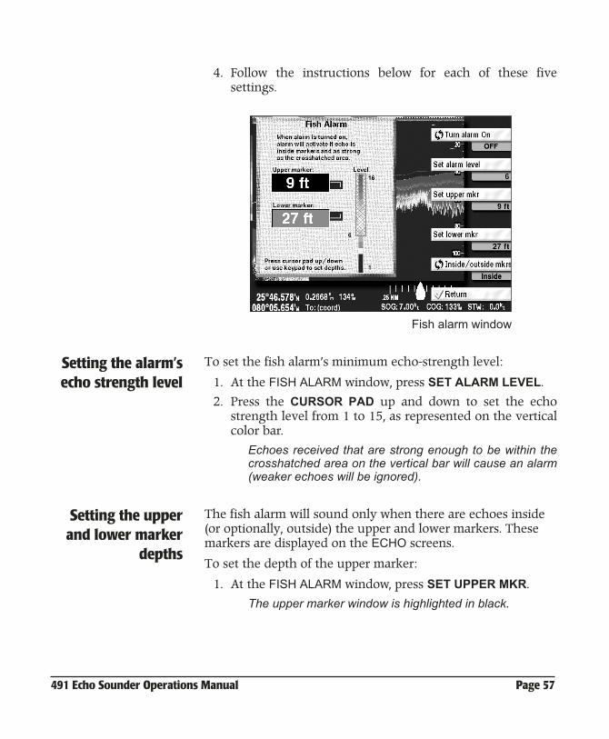
4. Follow the instructions below for each of these fivesettings.
Fish alarm window
Setting the alarm’secho strength level
To set the fish alarm’s minimum echo-strength level:
1. At the FISH ALARM window, press SET ALARM LEVEL.
2. Press the CURSOR PAD up and down to set the echostrength level from 1 to 15, as represented on the verticalcolor bar.
Echoes received that are strong enough to be within thecrosshatched area on the vertical bar will cause an alarm(weaker echoes will be ignored).
Setting the upperand lower marker
depths
The fish alarm will sound only when there are echoes inside (or optionally, outside) the upper and lower markers. These markers are displayed on the ECHO screens.
To set the depth of the upper marker:
1. At the FISH ALARM window, press SET UPPER MKR.
The upper marker window is highlighted in black.
Page 58 491 Echo Sounder Operations Manual
2. Press the CURSOR PAD up or down to set the depth, oruse the KEYPAD to manually enter the desired depth.
The depth is displayed in the tab below the SET UPPERMKR key.
To set the depth of the lower marker:
1. At the FISH ALARM window, press SET LOWER MKR.
The lower marker window is highlighted in black.
2. Press the CURSOR PAD up or down to set the depth, oruse the KEYPAD to manually enter the desired depth.
The depth is displayed in the tab below the SET LOWERMKR key.
Setting inside oroutside fish
markers
If you designate the markers as inside markers, the fish alarm sounds when fish are detected within these markers. If you set these markers as outside markers, the fish alarm sounds when fish are detected outside of these markers.
To set the markers to inside or outside, at the FISH ALARM window, press INSIDE/OUTSIDE MKRS to toggle between the inside and outside settings. The setting is displayed in the tab below the INSIDE/OUTSIDE MKRS key.
Turning the fishalarm on and off
To turn the alarm on, at the FISH ALARM window, press TURN ALARM ON. Generally, you’ll want to turn the alarm on after making all the other settings.
To turn the alarm off, press TURN ALARM OFF.
The alarm When fish are detected, the alert tone sounds and the message “FISH!” is displayed. This message clears automatically after 20 seconds and the alarm is rearmed.
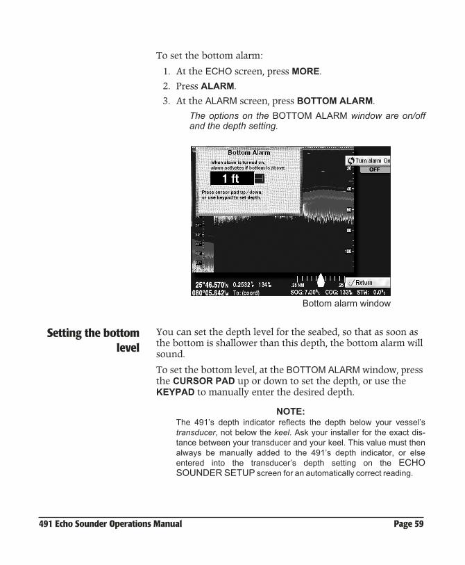
Setting the bottom alarmWhen the bottom alarm is set, an alarm sounds if the echo sounder detects that the bottom is shallower than the limit you’ve set.
491 Echo Sounder Operations Manual Page 59
To set the bottom alarm:
1. At the ECHO screen, press MORE.
2. Press ALARM.
3. At the ALARM screen, press BOTTOM ALARM.
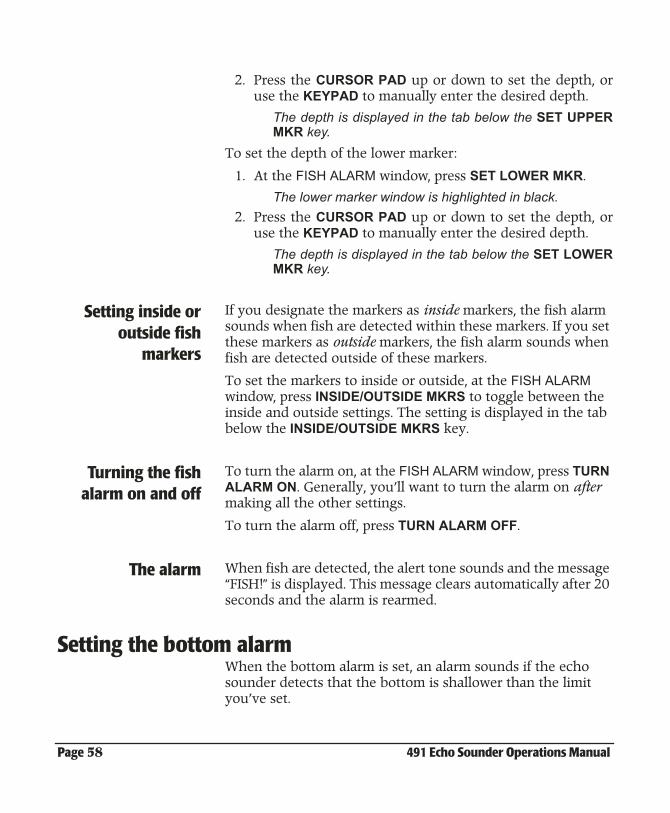
The options on the BOTTOM ALARM window are on/offand the depth setting.
Bottom alarm window
Setting the bottomlevel
You can set the depth level for the seabed, so that as soon as the bottom is shallower than this depth, the bottom alarm will sound.
To set the bottom level, at the BOTTOM ALARM window, press the CURSOR PAD up or down to set the depth, or use the KEYPAD to manually enter the desired depth.
NOTE:The 491’s depth indicator reflects the depth below your vessel’stransducer, not below the keel. Ask your installer for the exact dis-tance between your transducer and your keel. This value must thenalways be manually added to the 491’s depth indicator, or elseentered into the transducer’s depth setting on the ECHOSOUNDER SETUP screen for an automatically correct reading.
Page 60 491 Echo Sounder Operations Manual
Turning the bottomalarm on and off
To turn the alarm on, at the BOTTOM ALARM window, press TURN ALARM ON. To turn the alarm off, press TURN ALARM OFF.
The alarm When the bottom is detected, the alert tone sounds and the message “Bottom Collision!” is displayed. This message clears automatically after 20 seconds, and the alarm is reset.
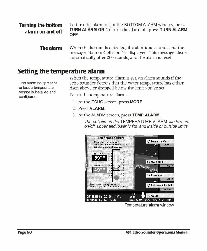
Setting the temperature alarm When the temperature alarm is set, an alarm sounds if the echo sounder detects that the water temperature has either risen above or dropped below the limit you’ve set.
To set the temperature alarm:
1. At the ECHO screen, press MORE.
2. Press ALARM.
3. At the ALARM screen, press TEMP ALARM.
The options on the TEMPERATURE ALARM window areon/off, upper and lower limits, and inside or outside limits.
Temperature alarm window
This alarm isn’t present unless a temperature sensor is installed and configured.
491 Echo Sounder Operations Manual Page 61
Setting the upperand lower
temperature limits
You can set the upper and lower temperature limits. When the water temperature is either inside or outside these limits, the temperature alarm will sound.
To set the upper temperature limit:
1. At the TEMPERATURE ALARM window, press SET UPPERLIMIT.
The upper limit window is highlighted in black.
2. Press the CURSOR PAD up or down to set thetemperature, or use the KEYPAD to manually enter thedesired temperature.
The temperature is displayed in the tab just below theSET UPPER LIMIT key.
To set the lower temperature limit:
1. At the TEMPERATURE ALARM window, press SETLOWER LIMIT.
The lower limit window is highlighted in black.
2. Press the CURSOR PAD up or down to set thetemperature, or use the KEYPAD to enter the desiredtemperature.
The temperature is displayed in the tab just below theSET LOWER LIMIT key.
Setting inside oroutside
temperature limits
If you set the upper and lower temperature limits as inside limits, the temperature alarm sounds when the temperature is detected within these limits. If you set these limits as outside limits, the temperature alarm sounds when the temperature is detected outside of these limits.
Press INSIDE/OUTSIDE LIMITS on the TEMPERATURE ALARM window to switch between the inside and outside settings. The current setting is displayed in the tab just below the INSIDE/OUTSIDE LIMITS key.
Turning thetemperature alarm
on and off
To turn the alarm on, at the TEMPERATURE ALARM window, press TURN ALARM ON. To turn the alarm off, press TURN ALARM OFF.
Page 62 491 Echo Sounder Operations Manual
The alarm When the temperature alarm sounds, an alert message is displayed. This message clears automatically after 20 seconds and the alarm is reset.
491 Echo Sounder Operations Manual Page 63
8Troubleshooting 491 Operations
Troubleshooting the echo sounder . . . . . . . 8-64
Checking the transducer . . . . . . . . . . . . . . . . . . 8-65
This chapter explains how to troubleshoot the echo sounder system before returning the equipment for factory service.
Page 64 491 Echo Sounder Operations Manual
Troubleshooting the echo sounder
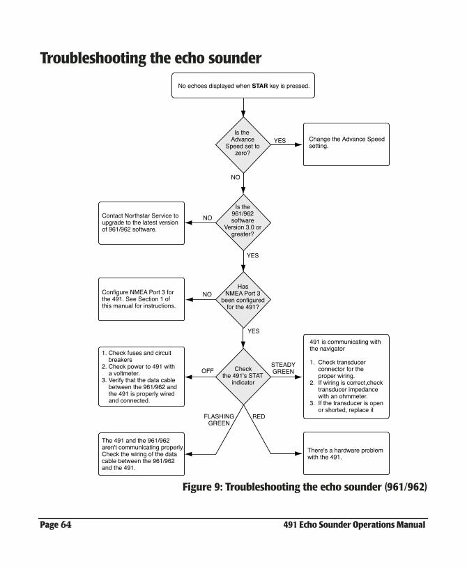
Figure 9: Troubleshooting the echo sounder (961/962)
No echoes displayed when STAR key is pressed.
Is the961/962software
Version 3.0 orgreater?
HasNMEA Port 3
been configuredfor the 491?
Checkthe 491's STAT
indicator
Is the Advance
Speed set tozero?
YES
YES
YES
NO
NO
NO
OFFSTEADYGREEN
FLASHINGGREEN
RED
Contact Northstar Service toupgrade to the latest versionof 961/962 software.
Change the Advance Speed setting.
Configure NMEA Port 3 for the 491. See Section 1 of this manual for instructions.
1. Check fuses and circuit breakers2. Check power to 491 with a voltmeter.3. Verify that the data cable between the 961/962 and the 491 is properly wired and connected.
491 is communicating withthe navigator
1. Check transducer connector for the proper wiring.2. If wiring is correct,check transducer impedance with an ohmmeter.3. If the transducer is open or shorted, replace it
There's a hardware problemwith the 491.
The 491 and the 961/962 aren't communicating properly.Check the wiring of the datacable between the 961/962 and the 491.
491 Echo Sounder Operations Manual Page 65
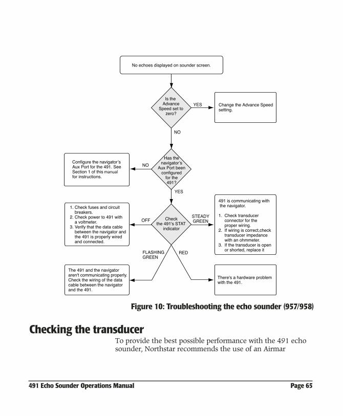
Figure 10: Troubleshooting the echo sounder (957/958)
Checking the transducerTo provide the best possible performance with the 491 echo sounder, Northstar recommends the use of an Airmar
No echoes displayed on sounder screen.
Has thenavigatorʼs
Aux Port beenconfigured
for the491?
Checkthe 491's STAT
indicator
Is the Advance
Speed set tozero?
YES
NO
YES
NO
OFFSTEADYGREEN
Change the Advance Speed setting.
Configure the navigatorʼsAux Port for the 491. See Section 1 of this manual for instructions.
1. Check fuses and circuit breakers.2. Check power to 491 with a voltmeter.3. Verify that the data cable between the navigator and the 491 is properly wired and connected.
491 is communicating with the navigator. 1. Check transducer connector for the proper wiring.2. If wiring is correct,check transducer impedance with an ohmmeter.3. If the transducer is open or shorted, replace it
There's a hardware problemwith the 491.
The 491 and the navigatoraren't communicating properly.Check the wiring of the datacable between the navigatorand the 491.
FLASHINGGREEN
RED
Page 66 491 Echo Sounder Operations Manual
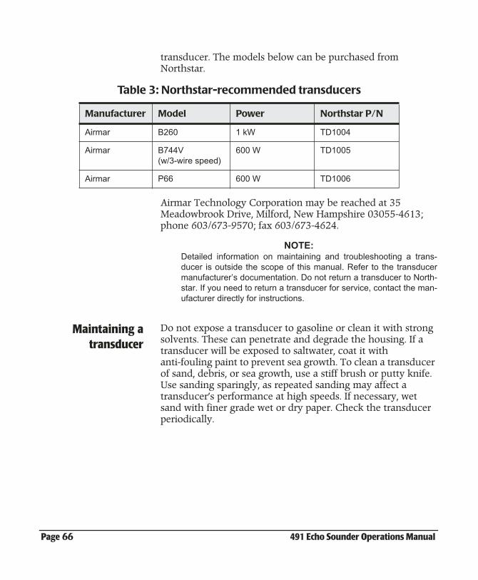
transducer. The models below can be purchased from Northstar.
Airmar Technology Corporation may be reached at 35 Meadowbrook Drive, Milford, New Hampshire 03055-4613; phone 603/673-9570; fax 603/673-4624.
NOTE:Detailed information on maintaining and troubleshooting a trans-ducer is outside the scope of this manual. Refer to the transducermanufacturer’s documentation. Do not return a transducer to North-star. If you need to return a transducer for service, contact the man-ufacturer directly for instructions.
Maintaining atransducer
Do not expose a transducer to gasoline or clean it with strong solvents. These can penetrate and degrade the housing. If a transducer will be exposed to saltwater, coat it with anti-fouling paint to prevent sea growth. To clean a transducer of sand, debris, or sea growth, use a stiff brush or putty knife. Use sanding sparingly, as repeated sanding may affect a transducer’s performance at high speeds. If necessary, wet sand with finer grade wet or dry paper. Check the transducer periodically.
Table 3: Northstar-recommended transducers
Manufacturer Model Power Northstar P/N
Airmar B260 1 kW TD1004
Airmar B744V(w/3-wire speed)
600 W TD1005
Airmar P66 600 W TD1006
491 Echo Sounder Operations Manual Page 67
A 491 Features and Specifications
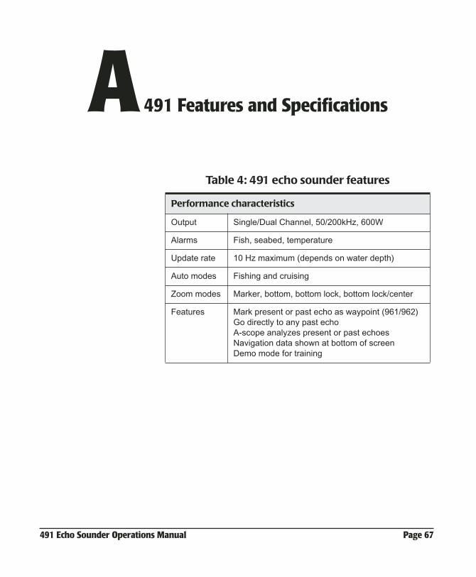
Table 4: 491 echo sounder features
Performance characteristics
Output Single/Dual Channel, 50/200kHz, 600W
Alarms Fish, seabed, temperature
Update rate 10 Hz maximum (depends on water depth)
Auto modes Fishing and cruising
Zoom modes Marker, bottom, bottom lock, bottom lock/center
Features Mark present or past echo as waypoint (961/962)Go directly to any past echoA-scope analyzes present or past echoesNavigation data shown at bottom of screenDemo mode for training
Page 68 491 Echo Sounder Operations Manual
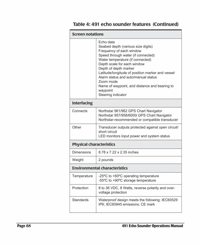
Screen notations
Echo dataSeabed depth (various size digits)Frequency of each windowSpeed through water (if connected)Water temperature (if connected)Depth scale for each windowDepth of depth markerLatitude/longitude of position marker and vesselAlarm status and auto/manual statusZoom modeName of waypoint, and distance and bearing to waypointSteering indicator
Interfacing
Connects Northstar 961/962 GPS Chart NavigatorNorthstar 957/958/6000i GPS Chart NavigatorNorthstar-recommended or compatible transducer
Other Transducer outputs protected against open circuit/short circuitLED monitors input power and system status
Physical characteristics
Dimensions 8.78 x 7.22 x 2.35 inches
Weight 2 pounds
Environmental characteristics
Temperature -25ºC to +60ºC operating temperature-55ºC to +90ºC storage temperature
Protection 8 to 36 VDC, 8 Watts, reverse polarity and over-voltage protection
Standards Waterproof design meets the following: IEC60529 IP6; IEC60945 emissions; CE mark
Table 4: 491 echo sounder features (Continued)
491 Echo Sounder Operations Manual Page 69
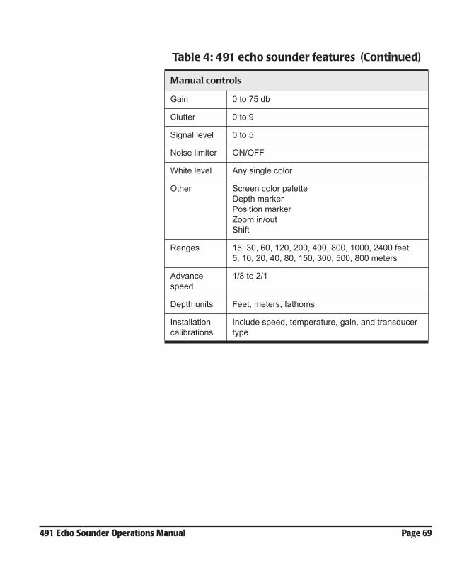
Manual controls
Gain 0 to 75 db
Clutter 0 to 9
Signal level 0 to 5
Noise limiter ON/OFF
White level Any single color
Other Screen color paletteDepth markerPosition markerZoom in/outShift
Ranges 15, 30, 60, 120, 200, 400, 800, 1000, 2400 feet 5, 10, 20, 40, 80, 150, 300, 500, 800 meters
Advance speed
1/8 to 2/1
Depth units Feet, meters, fathoms
Installation calibrations
Include speed, temperature, gain, and transducer type
Table 4: 491 echo sounder features (Continued)

Page 70 491 Echo Sounder Operations Manual
491 Echo Sounder Operations Manual Page 71
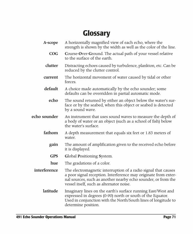
GGlossary
A-scope A horizontally magnified view of each echo, where the strength is shown by the width as well as the color of the line.
COG Course-Over-Ground. The actual path of your vessel relative to the surface of the earth.
clutter Distracting echoes caused by turbulence, plankton, etc. Can be reduced by the clutter control.
current The horizontal movement of water caused by tidal or other forces.
default A choice made automatically by the echo sounder; some defaults can be overridden in partial automatic mode.
echo The sound returned by either an object below the water’s sur-face or by the seabed, when this object or seabed is detected by a sound wave.
echo sounder An instrument that uses sound waves to measure the depth of a body of water or an object (such as a school of fish) below the water’s surface.
fathom A depth measurement that equals six feet or 1.83 meters of water.
gain The amount of amplification given to the received echo before it is displayed.
GPS Global Positioning System.
hue The gradations of a color.
interference The electromagnetic interruption of a radio signal that causes a poor signal reception. Interference may originate from exter-nal sources, such as another nearby echo sounder, or from the vessel itself, such as alternator noise.
latitude Imaginary lines on the earth's surface running East/West and expressed in degrees (0-90) north or south of the Equator. Used in conjunction with the North/South lines of longitude to determine position.
Page 72 491 Echo Sounder Operations Manual
longitude Imaginary lines on the Earth's surface running North/South and expressed in degrees (0-180) east or west of the Prime Meridian (a line running from the North to South Pole, passing through Greenwich, England).
meter A unit of measurement (length) equal to 39.37 inches, slightly more than a standard yard.
nautical mile (nm) An international unit equal to 6,076.115 feet (1,852 meters) used officially in the U.S. since 1959. A nautical mile is about 800 feet more than a statute mile. One nm is equal to 1 minute of latitude.
ping A pulse transmitted from the 491 echo sounder. Also, the act of transmitting a pulse from the echo sounder ("pinging").
SOG Speed Over Ground. The actual speed of your vessel relative to the earth, not the water.
tide The vertical rise and fall of water caused by the gravitational pull of the moon and sun.
transducer The device mounted through the hull to send and receive ultrasonic beams that determine seabed conditions and locate fish.
waypoint A particular location, saved by marking fish on the echo sounder’s LIVE-DATA screen, which is used as an intermediate or final destination.