Embed Size (px)
Citation preview
IOtech • 25971 Cannon Road • Cleveland, OH 44146 • (440) 439-4091 • Fax (440) 439-4093 • [email protected] • iotech.com
1
Industrial
Application Note #93
Steam Turbine Rotor Testingusing the ZonicBook
ZonicBook
Steam Turbine Gas Compressor
Desktop orNotebook PC
2 2 2 2
ProximitySensors
Tach Pickup
Bearings
Tach SignalTach Signal
ProximitySensors
Tach Signals
Tach Pickups
BearingsBearings
Tach Pickup
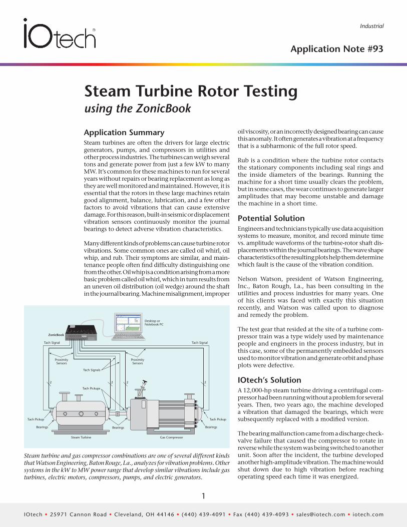
Steam turbine and gas compressor combinations are one of several different kinds that Watson Engineering, Baton Rouge, La., analyzes for vibration problems. Other systems in the kW to MW power range that develop similar vibrations include gas turbines, electric motors, compressors, pumps, and electric generators.
Application SummarySteam turbines are often the drivers for large electric generators, pumps, and compressors in utilities and other process industries. The turbines can weigh several tons and generate power from just a few kW to many MW. It’s common for these machines to run for several years without repairs or bearing replacement as long as they are well monitored and maintained. However, it is essential that the rotors in these large machines retain good alignment, balance, lubrication, and a few other factors to avoid vibrations that can cause extensive damage. For this reason, built-in seismic or displacement vibration sensors continuously monitor the journal bearings to detect adverse vibration characteristics.
Many different kinds of problems can cause turbine rotor vibrations. Some common ones are called oil whirl, oil whip, and rub. Their symptoms are similar, and main-tenance people often find difficulty distinguishing one from the other. Oil whip is a condition arising from a more basic problem called oil whirl, which in turn results from an uneven oil distribution (oil wedge) around the shaft in the journal bearing. Machine misalignment, improper
oil viscosity, or an incorrectly designed bearing can cause this anomaly. It often generates a vibration at a frequency that is a subharmonic of the full rotor speed.
Rub is a condition where the turbine rotor contacts the stationary components including seal rings and the inside diameters of the bearings. Running the machine for a short time usually clears the problem, but in some cases, the wear continues to generate larger amplitudes that may become unstable and damage the machine in a short time.
Potential SolutionEngineers and technicians typically use data acquisition systems to measure, monitor, and record minute time vs. amplitude waveforms of the turbine-rotor shaft dis-placements within the journal bearings. The wave shape characteristics of the resulting plots help them determine which fault is the cause of the vibration condition.
Nelson Watson, president of Watson Engineering, Inc., Baton Rough, La., has been consulting in the utilities and process industries for many years. One of his clients was faced with exactly this situation recently, and Watson was called upon to diagnose and remedy the problem.
The test gear that resided at the site of a turbine com-pressor train was a type widely used by maintenance people and engineers in the process industry, but in this case, some of the permanently embedded sensors used to monitor vibration and generate orbit and phase plots were defective.
IOtech’s SolutionA 12,000-hp steam turbine driving a centrifugal com-pressor had been running without a problem for several years. Then, two years ago, the machine developed a vibration that damaged the bearings, which were subsequently replaced with a modified version.
The bearing malfunction came from a discharge check-valve failure that caused the compressor to rotate in reverse while the system was being switched to another unit. Soon after the incident, the turbine developed another high-amplitude vibration. The machine would shut down due to high vibration before reaching operating speed each time it was energized.
IOtech • 25971 Cannon Road • Cleveland, OH 44146 • (440) 439-4091 • Fax (440) 439-4093 • [email protected] • iotech.com
2
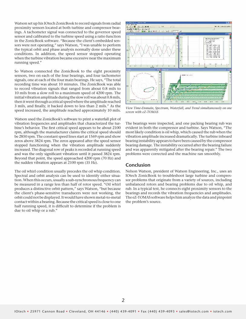
View Time-Domain, Spectrum, Waterfall, and Trend simultaneously on one screen with eZ-TOMAS
Watson set up his IOtech ZonicBook to record signals from radial proximity sensors located at both turbine and compressor bear-ings. A tachometer signal was connected to the governor speed sensor and calibrated to the turbine speed using a ratio function in the ZonicBook software. “Because the client’s embedded sen-sors were not operating,” says Watson, “I was unable to perform the typical orbit and phase analysis normally done under these conditions. In addition, the speed sensor stopped operating when the turbine vibration became excessive near the maximum running speed.”
So Watson connected the ZonicBook to the eight proximity sensors, two on each of the four bearings, and four tachometer signals, one at each of the four main bearings. He says, “The total recording time was about 10 minutes. The ZonicBook was able to record vibration signals that ranged from about 0.8 mils to 10 mils from a slow roll to a maximum speed of 4200 rpm. The initial vibration amplitude during the slow roll was about 0.8 mils, then it went through a critical speed where the amplitude reached 3 mils, and finally, it backed down to less than 2 mils.” As the speed increased, the amplitude reached approximately 10 mils.
Watson used the ZonicBook’s software to print a waterfall plot of vibration frequencies and amplitudes that characterized the tur-bine’s behavior. The first critical speed appears to be about 2100 rpm, although the manufacturer claims the critical speed should be 2850 rpm. The constant speed lines start at 1569 rpm and show zeros above 3824 rpm. The zeros appeared after the speed sensor stopped functioning when the vibration amplitude suddenly increased. The diagonal row of peaks is recorded at running speed and was the only significant vibration until it passed 3824 rpm. Beyond that point, the speed approached 4200 rpm (70 Hz) and the sudden vibration appears at 2100 rpm (35 Hz).
The oil whirl condition usually precedes the oil whip condition. Spectral and orbit analysis can be used to identify either situa-tion. When this occurs, usually a sub-synchronous frequency can be measured in a range less than half of rotor speed. “Oil whirl produces a distinctive orbit pattern,” says Watson, “but because the client’s phase-sensitive transducers were not working, the orbit could not be displayed. It would have shown metal-to-metal contact within a bearing. Because the critical speed is close to one half running speed, it is difficult to determine if the problem is due to oil whip or a rub.”
The bearings were inspected, and one packing bearing rub was evident in both the compressor and turbine. Says Watson, “The most likely condition is oil whip, which caused the rub when the vibration amplitude increased dramatically. The turbine inboard bearing instability appears to have been caused by the compressor bearing damage. The instability occurred after the bearing failure and was apparently mitigated after the bearing repair.” The two problems were corrected and the machine ran smoothly.
ConclusionNelson Watson, president of Watson Engineering, Inc., uses an IOtech ZonicBook to troubleshoot large turbine and compres-sor problems that originate from a variety of sources, including unbalanced rotors and bearing problems due to oil whip, and rub. In a typical test, he connects eight proximity sensors to the bearings and records the vibration frequencies and amplitudes. The eZ-TOMAS software helps him analyze the data and pinpoint the problem’s source.
IOtech • 25971 Cannon Road • Cleveland, OH 44146 • (440) 439-4091 • Fax (440) 439-4093 • [email protected] • iotech.com
3
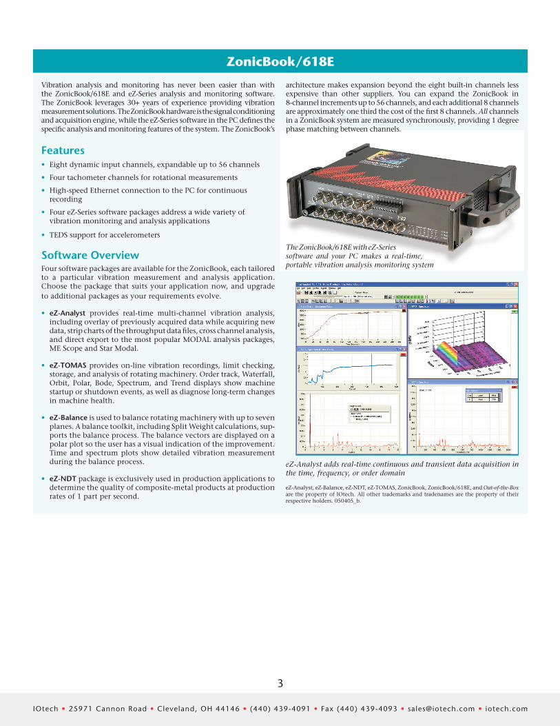
eZ-Analyst adds real-time continuous and transient data acquisition in the time, frequency, or order domain
eZ-Analyst, eZ-Balance, eZ-NDT, eZ-TOMAS, ZonicBook, ZonicBook/618E, and Out-of-the-Box are the property of IOtech. All other trademarks and tradenames are the property of their respective holders. 050405_b.
ZonicBook/618E
Features• Eight dynamic input channels, expandable up to 56 channels
• Four tachometer channels for rotational measurements
• High-speed Ethernet connection to the PC for continuous recording
• Four eZ-Series software packages address a wide variety of vibration monitoring and analysis applications
• TEDS support for accelerometers
Software OverviewFour software packages are available for the ZonicBook, each tailored to a particular vibration measurement and analysis application. Choose the package that suits your application now, and upgrade to additional packages as your requirements evolve.
• eZ-Analyst provides real-time multi- channel vibration analysis, including overlay of previously acquired data while acquiring new data, strip charts of the throughput data files, cross channel analysis, and direct export to the most popular MODAL analysis packages, ME Scope and Star Modal.
• eZ-TOMAS provides on-line vibration recordings, limit checking, storage, and analysis of rotating machinery. Order track, Waterfall, Orbit, Polar, Bode, Spectrum, and Trend displays show machine startup or shutdown events, as well as diagnose long-term changes in machine health.
• eZ-Balance is used to balance rotating machinery with up to seven planes. A balance toolkit, including Split Weight calculations, sup-ports the balance process. The balance vectors are displayed on a polar plot so the user has a visual indication of the improvement. Time and spectrum plots show detailed vibration measurement during the balance process.
• eZ-NDT package is exclusively used in production applications to determine the quality of composite-metal products at production rates of 1 part per second.
The ZonicBook/618E with eZ-Series software and your PC makes a real-time, portable vibration analysis monitoring system
Vibration analysis and monitoring has never been easier than with the ZonicBook/618E and eZ-Series analysis and monitoring software. The ZonicBook leverages 30+ years of experience providing vibration measurement solutions. The ZonicBook hardware is the signal conditioning and acquisition engine, while the eZ-Series software in the PC defines the specific analysis and monitoring features of the system. The ZonicBook’s
architecture makes expansion beyond the eight built-in channels less expensive than other suppliers. You can expand the ZonicBook in 8- channel increments up to 56 channels, and each additional 8 channels are approximately one third the cost of the first 8 channels. All channels in a ZonicBook system are measured synchronously, providing 1 degree phase matching between channels.