Embed Size (px)
Citation preview

Instruction ManualIM/AM/E Issue 11
Electromagnetic FlowmeterAquaMaster™ Explorer

ABBEN ISO 9001:2000
Cert. No. Q 05907
EN 29001 (ISO 9001)
Lenno, Italy – Cert. No. 9/90A
Stonehouse, U.K.
����
Electrical Safety
This equipment complies with the requirements of CEI/IEC 61010-1:2001-2 'Safety Requirements for ElectricalEquipment for Measurement, Control and Laboratory Use'. If the equipment is used in a manner NOT specified by theCompany, the protection provided by the equipment may be impaired.
Symbols
One or more of the following symbols may appear on the equipment labelling:
Warning – Refer to the manual for instructions Direct current supply only
Caution – Risk of electric shock Alternating current supply only
Protective earth (ground) terminal Both direct and alternating current supply
Earth (ground) terminal The equipment is protected through double insulation
The Company
We are an established world force in the design and manufacture of instrumentation forindustrial process control, flow measurement, gas and liquid analysis and environmentalapplications.
As a part of ABB, a world leader in process automation technology, we offer customersapplication expertise, service and support worldwide.
We are committed to teamwork, high quality manufacturing, advanced technology andunrivalled service and support.
The quality, accuracy and performance of the Company’s products result from over 100years experience, combined with a continuous program of innovative design anddevelopment to incorporate the latest technology.
The UKAS Calibration Laboratory No. 0255 is just one of the ten flow calibration plantsoperated by the Company and is indicative of our dedication to quality and accuracy.
Information in this manual is intended only to assist our customers in the efficient operation of our equipment. Use of thismanual for any other purpose is specifically prohibited and its contents are not to be reproduced in full or part withoutprior approval of the Technical Publications Department.
Health and Safety
To ensure that our products are safe and without risk to health, the following points must be noted:
1. The relevant sections of these instructions must be read carefully before proceeding.2. Warning labels on containers and packages must be observed.3. Installation, operation, maintenance and servicing must only be carried out by suitably trained personnel and in accordance
with the information given.4. Normal safety precautions must be taken to avoid the possibility of an accident occurring when operating in conditions of
high pressure and/or temperature.5. Chemicals must be stored away from heat, protected from temperature extremes and powders kept dry. Normal safe
handling procedures must be used.6. When disposing of chemicals ensure that no two chemicals are mixed.
Safety advice concerning the use of the equipment described in this manual or any relevant hazard data sheets (where applicable) may be obtained from the Company address on the back cover, together with servicing and spares information.

Electromagnetic FlowmeterAquaMaster™ Explorer
IM/AM/E Issue 11 1
1 Introduction ...................................................................................................................................... 3
2 Mechanical Installation .................................................................................................................... 42.1 Unpacking ............................................................................................................................... 42.2 Installation Conditions .............................................................................................................. 42.3 Transmitter Dimensions ........................................................................................................... 9
2.3.1 Terminal Box – Sensor-mounted ................................................................................... 92.3.2 AquaMaster Explorer ................................................................................................... 10
2.4 GSM-equipped Transmitters .................................................................................................. 112.4.1 GSM Antenna Installation ............................................................................................ 112.4.2 Connecting a Remote Antenna .................................................................................... 122.4.3 Installing a SIM Card .................................................................................................... 13
3 Electrical Installation ..................................................................................................................... 143.1 Grounding ............................................................................................................................. 143.2 Connections .......................................................................................................................... 16
3.2.1 AquaMaster Explorer Connections – Bulgin Connectors .............................................. 163.2.2 AquaMaster Explorer Connections – MIL-style Connectors ......................................... 173.2.3 AquaMaster Explorer Connections – Use of Tamper-Detection Seals .......................... 18
3.3 Cables ................................................................................................................................... 193.3.1 Adaptor Cables – AquaMaster Explorer ....................................................................... 193.3.2 Conversion Kits – AquaMaster & AquaMaster Explorer ................................................ 203.3.3 Close-Coupled Integral Mounting Kit – AquaMaster Explorer ....................................... 20
3.4 Input/Output Connections ..................................................................................................... 213.4.1 Frequency Outputs ...................................................................................................... 213.4.2 Alarm Interface ............................................................................................................ 213.4.3 AquaMaster Explorer Input/Output Connections .......................................................... 223.4.4 Third party and standard output cables ....................................................................... 233.4.5 Local Computer Connection ........................................................................................ 233.4.6 Power Supply Connections ......................................................................................... 243.4.7 Pressure Transducer (Optional) .................................................................................... 253.4.8 Anti-tamper Protection ................................................................................................ 26
Electromagnetic FlowmeterAquaMaster™ Explorer
2 IM/AM/E Issue 11
4 Start-Up And Operation ................................................................................................................. 284.1 Connecting Batteries .............................................................................................................. 284.2 Start-up ................................................................................................................................. 294.3 Display Activation ................................................................................................................... 294.4 Replacing a Battery ................................................................................................................ 304.5 Servicing Plugs and Sockets .................................................................................................. 31
4.5.1 Service Intervals ........................................................................................................... 314.5.2 Equipment Required .................................................................................................... 324.5.3 Preparation .................................................................................................................. 324.5.4 Stage 1 – Oxide Removal and Cleaning ....................................................................... 334.5.5 Stage 2 – Oxide Prevention .......................................................................................... 344.5.6 Completion Tasks ........................................................................................................ 34
4.6 Accessories/Spares Kits ........................................................................................................ 35
5 Specification ................................................................................................................................... 37
Appendix A Hazardous Area Protection ............................................................................................. 47A.1 GSM-Equipped Units – Safety Precautions ............................................................................47
Electromagnetic FlowmeterAquaMaster™ Explorer 1 Introduction
IM/AM/E Issue 11 3
1 IntroductionAquaMasterTM is a range of high performance electromagnetic flowmeters for the measurement ofelectrically conductive fluids and are normally supplied as factory configured, calibrated systems.
This manual provides end-user details for AquaMaster Explorer Integral and Remote transmitters. Fordetails of the sensor used with the transmitter, please refer to the sensor manual supplied at time ofordering.
Warning.
� Installation and maintenance must be carried out only by suitably trained personnel.
� Read all relevant sections of this manual before selecting a location.
� The safety requirements of this equipment, any associated equipment and the local environment must be taken into consideration during installation.
� Install and use this equipment in accordance with relevant national and local standards.
� Specific safety precautions apply to the use of the GSM engine which forms part of the GSM-equipped version of this product. If the unit purchased has GSM-capability, read Appendix A on page 47 before selecting a location.

Electromagnetic FlowmeterAquaMaster™ Explorer 2 Mechanical Installation
4 IM/AM/E Issue 11
2 Mechanical Installation
2.1 Unpacking
2.2 Installation Conditions
Fig. 2.1 Unpacking
Caution. Do NOT exceed the maximum working pressure marked on the equipment.
Fig. 2.2 Spillage
Fig. 2.3 Vibration
Note. Metal case design shown.
Electromagnetic FlowmeterAquaMaster™ Explorer 2 Mechanical Installation
IM/AM/E Issue 11 5
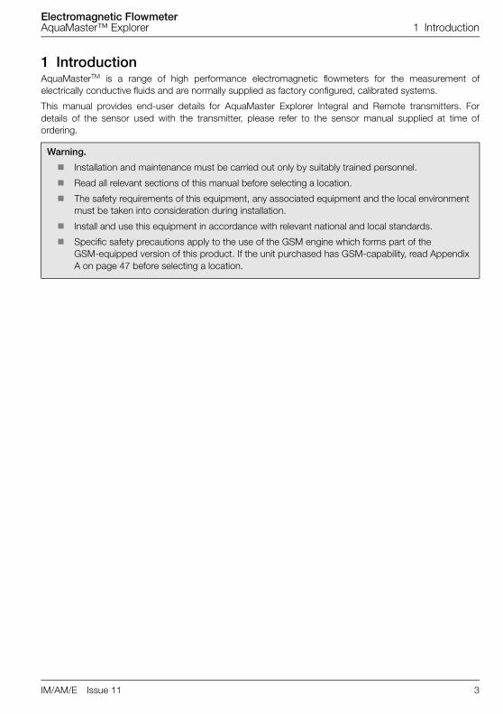
Fig. 2.4 Localized Heat
Fig. 2.5 Siting
Fig. 2.6 Within Temperature Limits
Fig. 2.7 Straight Pipe Requirements
Allow Room to Read Display
60 °C (140 °F) Maximum
–20 °C (–4 °F) Minimum
–10 °C(14 °F)
Minimum
80 °C (176 °F) Maximum
0 x Pipe Dia. 0 x Pipe Dia.
Minimum Minimum
Flow Direction

Electromagnetic FlowmeterAquaMaster™ Explorer 2 Mechanical Installation
6 IM/AM/E Issue 11
Fig. 2.8 Fluid Level
Fig. 2.9 Shade
Fig. 2.10 Within Environmental Rating
Fig. 2.11 Above Ground
<2 m 78 in.)
Submerged–9 Months
Accrued TimeIP68 (NEMA 6P)ENCLOSURE 6P
Supports
Electromagnetic FlowmeterAquaMaster™ Explorer 2 Mechanical Installation
IM/AM/E Issue 11 7
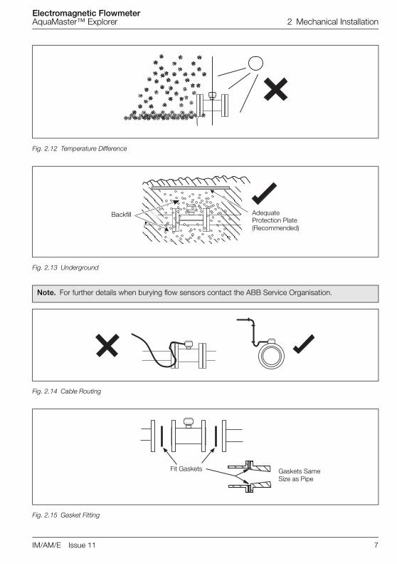
Fig. 2.12 Temperature Difference
Fig. 2.13 Underground
Note. For further details when burying flow sensors contact the ABB Service Organisation.
Fig. 2.14 Cable Routing
Fig. 2.15 Gasket Fitting
AdequateProtection Plate(Recommended)
Backfill
Fit Gaskets Gaskets SameSize as Pipe

Electromagnetic FlowmeterAquaMaster™ Explorer 2 Mechanical Installation
8 IM/AM/E Issue 11
Fig. 2.16 Access to Transmitter
Fig. 2.17 Separation of Sensors
For Access to Display, and Communication Connector
0.7 m (2.3 ft) Minimum

Electromagnetic FlowmeterAquaMaster™ Explorer 2 Mechanical Installation
IM/AM/E Issue 11 9
2.3 Transmitter Dimensions
2.3.1 Terminal Box – Sensor-mounted
Dimensions in mm (in)
Fig. 2.18 Sensor-mounted Terminal Box
Dimensions in mm (in)
Fig. 2.19 Round Terminal Box
61 (2.4)
M20 Cable Gland Shown
95 (3.75)
80 (3.15)30 (1.2)
100 (3.93)
36.5 (1.43)
62 (2.44)
80 (3.2)

Electromagnetic FlowmeterAquaMaster™ Explorer 2 Mechanical Installation
10 IM/AM/E Issue 11
2.3.2 AquaMaster Explorer
Dimensions in mm (in)
Fig. 2.20 AquaMaster Explorer – Dimensions
Dimensions in mm (in)
Fig. 2.21 AquaMaster Explorer Battery Pack Dimensions
AquaMaster
Ø6.5 (0.25)
Ø13 (0.50)
115 (4.50)
177 (7.0)
50 (2.0)
185 (7.3)*
21 (0.80)
136 (5.4)
Remote Mounted Explorer
Transmitter
Sensor-mounted Explorer
Transmitter
105 (4.1) *For units fitted with
MIL-style sockets
180 (7.0)with
connectors
135 (5.30) 70 (2.75)
135 (5.30)
8 (0.30)

Electromagnetic FlowmeterAquaMaster™ Explorer 2 Mechanical Installation
IM/AM/E Issue 11 11
2.4 GSM-equipped Transmitters
2.4.1 GSM Antenna InstallationBefore deciding on an antenna mounting location, check that the local signal strength for the chosenmobile phone network is satisfactory. Use the GSM-equipped transmitter's integral signal strength testfacility to establish signal strength. Refer to 'Commissioning test for signal strength' in the Quick ReferenceGuide for the AquaMaster S with GSM (IM/AMG–QRG).
If a GSM-equipped transmitter is not available, a standard mobile phone on the same network, positionedas close as possible to the intended location, will give a good indication of local signal strength. For GSMand logger download services, a minimum of two visible signal strength indicator 'bars' are recommended.For SMS text, a minimum of one visible signal strength indicator 'bar' is recommended.
The following must also be observed when deciding on the antenna mounting location:
� For best results, mount the antenna as high above local ground level as possible.
� If the antenna must be mounted below ground, achieve optimum results by ensuring:
– there is a strong mobile phone network signal at ground level
– the antenna is mounted 50 mm below the chamber cover, which must be plastic – seeFig. 2.22
� Ensure the antenna will not become submerged under water – see Fig. 2.22.
� Metallic enclosures will seriously degrade the signal. If an enclosure is used it must be non-metallic.
� Do not mount the antenna closer than 50 mm to any solid wall or surface – see Fig. 2.23.
� Do not mount the antenna beneath a solid surface (e.g. metal cover, floor/ceiling, etc).
Fig. 2.22 GSM Antenna Installation
Remote Antenna Integral Antenna
50 mm (2.0 in) 50 mm (2.0 in)

Electromagnetic FlowmeterAquaMaster™ Explorer 2 Mechanical Installation
12 IM/AM/E Issue 11
2.4.2 Connecting a Remote AntennaReferring to Fig. 2.24:
1. Remove the cover A from the socket on top of the transmitter.
2. Gently push the antenna plug B into the socket, then twist the screw ring clockwise until locked.
Fig. 2.23 GSM Antenna Installation
Fig. 2.24 Connecting a Remote Antenna – AquaMaster Explorer
>50 mm (2.0 in)
��������
� �
Electromagnetic FlowmeterAquaMaster™ Explorer 2 Mechanical Installation
IM/AM/E Issue 11 13
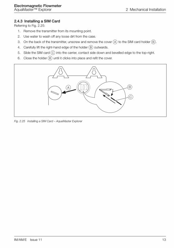
2.4.3 Installing a SIM CardReferring to Fig. 2.25:
1. Remove the transmitter from its mounting point.
2. Use water to wash off any loose dirt from the case.
3. On the back of the transmitter, unscrew and remove the cover A to the SIM card holder B.
4. Carefully lift the right-hand edge of the holder B outwards.
5. Slide the SIM card C into the carrier, contact side down and bevelled edge to the top-right.
6. Close the holder B until it clicks into place and refit the cover.
Fig. 2.25 Installing a SIM Card – AquaMaster Explorer
� �
�
Electromagnetic FlowmeterAquaMaster™ Explorer 3 Electrical Installation
14 IM/AM/E Issue 11
3 Electrical Installation
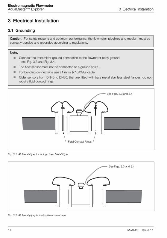
3.1 Grounding
Caution. For safety reasons and optimum performance, the flowmeter, pipelines and medium must be correctly bonded and grounded according to regulations.
Note.
� Connect the transmitter ground connection to the flowmeter body ground – see Fig. 3.3 and Fig. 3.4.
� The flow sensor must not be connected to a ground spike.
� For bonding connections use ≥4 mm2 (<10AWG) cable.
� Older sensors from DN40 to DN80, that are fitted with bare metal stainless steel flanges, do notrequire fluid contact rings.
Fig. 3.1 All Metal Pipe, Including Lined Metal Pipe
Fig. 3.2 All Metal pipe, including lined metal pipe
Fluid Contact Rings
See Figs. 3.3 and 3.4
See Figs. 3.3 and 3.4

Electromagnetic FlowmeterAquaMaster™ Explorer 3 Electrical Installation
IM/AM/E Issue 11 15
Fig. 3.3 Battery-powered AquaMaster Explorer Transmitter Mounted in a Chamber
Fig. 3.4 Battery-powered AquaMaster Explorer Transmitter Mounted in a Cabinet

Electromagnetic FlowmeterAquaMaster™ Explorer 3 Electrical Installation
16 IM/AM/E Issue 11
3.2 Connections
3.2.1 AquaMaster Explorer Connections – Bulgin ConnectorsReferring to Fig. 3.5:
1. Remove the screwed cap A on the sensor connector.
2. Gently push the sensor plug B into the socket and rotate it until it engages, then tighten the lockingring.
Notes.
� If the sensor cable is fitted with the metal MIL-spec connector, connection is via the MIL-specsensor cable adapter (part number WEBC2001, available separately).
� If the sensor cable is terminated with flying leads, connection is via a sensor cable adapter box(part number WABC2024/B, available separately).
Fig. 3.5 AquaMaster Explorer – Sensor Connections (Bulgin)
Note. This arrangement is an option.
�
�
Electromagnetic FlowmeterAquaMaster™ Explorer 3 Electrical Installation
IM/AM/E Issue 11 17
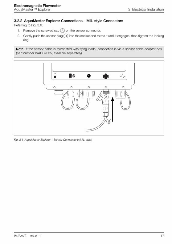
3.2.2 AquaMaster Explorer Connections – MIL-style ConnectorsReferring to Fig. 3.6:
1. Remove the screwed cap A on the sensor connector.
2. Gently push the sensor plug B into the socket and rotate it until it engages, then tighten the lockingring.
Note. If the sensor cable is terminated with flying leads, connection is via a sensor cable adapter box(part number WABC2035, available separately).
Fig. 3.6 AquaMaster Explorer – Sensor Connections (MIL-style)
�
�
Electromagnetic FlowmeterAquaMaster™ Explorer 3 Electrical Installation
18 IM/AM/E Issue 11
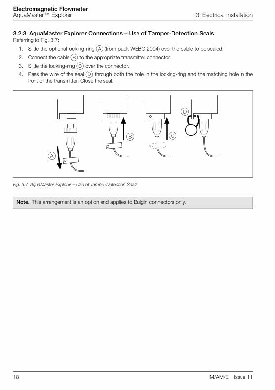
3.2.3 AquaMaster Explorer Connections – Use of Tamper-Detection SealsReferring to Fig. 3.7:
1. Slide the optional locking-ring A (from pack WEBC 2004) over the cable to be sealed.
2. Connect the cable B to the appropriate transmitter connector.
3. Slide the locking-ring C over the connector.
4. Pass the wire of the seal D through both the hole in the locking-ring and the matching hole in thefront of the transmitter. Close the seal.
Fig. 3.7 AquaMaster Explorer – Use of Tamper-Detection Seals
Note. This arrangement is an option and applies to Bulgin connectors only.
�
� �

Electromagnetic FlowmeterAquaMaster™ Explorer 3 Electrical Installation
IM/AM/E Issue 11 19
3.3 Input/Output Connections
3.3.1 Frequency Outputs
3.3.2 Alarm Interface
Caution.
� Refer to the associated Data Sheets for input/output ratings.
� Inductive loads must be suppressed or clamped to limit voltage swings
� Operation of outputs is programmable – see Quick Reference Programming Guide for details.
� External isolators are not normally required as the pulse and alarm circuit is electrically separated from all other AquaMaster connections.
� Capacitive loads must be inrush current limited.
� Fully-floating pulse outputs may be subject to static damage, e.g. connecting to a floating datalogger, unless 'COM' is operated within its galvanic isolation range (±35 V) from earth.
Fig. 3.8 Frequency Output Connections
Note. Outputs 1 & 2 are not polarity sensitive. The common connection for these outputs is designated ‘COM’.
Fig. 3.9 Alarm Output Connections – AquaMaster
Note. Output 3 is not polarity sensitive. The common connection for these outputs is designated ‘COM’.
Forward Flow
Reverse Flow6
Telemetry, Electronic Counters etc.
Counter/Totalizers
*Optional link for grounding floating output. See Caution above.PLC or Datalogger
Common
Input 1
Input 2
COM
O/P1
O/P2
I/POV*
COM
O/P1
O/P2and/or
Common
Alarm InputCOM
O/P 3

Electromagnetic FlowmeterAquaMaster™ Explorer 3 Electrical Installation
20 IM/AM/E Issue 11
3.3.3 AquaMaster Explorer Input/Output Connections
Fig. 3.10 AquaMaster Explorer – Bulgin Connectons (Connector, Remote version)
Fig. 3.11 AquaMaster Explorer – MIL Style Connectons (Connector, Remote version)
Pin (Bulgin)
Pin (MIL Style)
Signal Function Color (Output Cable)
1 A +V Scanreader +V Violet
2 B DATA Scanreader Data Blue
3 C O/P COM Output Common Yellow
4 D O/P2 Reverse Pulses or Direction Indicator Red
5 E O/P3 Alarm Output Brown
6 F O/P1 Forward Pulses or Forward & Reverse Pulses Orange
7 G 0V Scanreader 0V Screen
8 NC Not Used
Table 3.1 AquaMaster Explorer – Connector Input/Output Connections
������������
�
�
�
��
�
�
�
Pin View
������������
�
�
�
�
��
Pin View
Electromagnetic FlowmeterAquaMaster™ Explorer 3 Electrical Installation
IM/AM/E Issue 11 21
3.3.4 Third party and standard output cablesMost of the cables are designed to either plug or wire to the AquaMaster and the third party logger withoutrequiring any AquaMaster configuration. However in the case of connecting an AquaMaster to a RADCOMmultilog the configuration of the AquaMaster must be changed. This change is to set the function of output1 to pulse forward (>70=3) and reverse, and function of output 2 to reverse (>71=4).
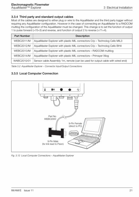
3.3.5 Local Computer Connection
Part Number Description
WEBC2011/M AquaMaster Explorer with plastic MIL connectors O/p – Technolog Cello MIL3
WEBC2012/M AquaMaster Explorer with plastic MIL connectors O/p – Technolog Cello BH4
WEBC2013/M AquaMaster Explorer with plastic MIL connectors – RADCOM multilog
WEBC2014/M AquaMaster Explorer with plastic MIL connectors – Primayer Xilog
WABC2010/01 Sensor cable Assembly 1m, remote (can be used for output cable with wired end)
Table 3.2 AquaMaster Explorer – Connector Input/Output Connections
Fig. 3.12 Local Computer Connections – AquaMaster Explorer
9-Pin Female(direct to PC)
9-Pin Male(for link lead to Psion)
Part NoWEBC2000

Electromagnetic FlowmeterAquaMaster™ Explorer 3 Electrical Installation
22 IM/AM/E Issue 11
3.3.6 Power Supply Connections
Warning.
� DISCONNECT THE SUPPLY FROM ANY CABLES BEING TERMINATED ON THETRANSMITTER.
� Electrical installation and earthing (grounding) must be in accordance with relevant national andlocal standards.
Note.
� Power supply connections/earthing arrangements are identical for cathodically protected remotetransmitter systems. For cathodically protected integral transmitter systems, follow cathodicinstallation practices.
� The AquaMaster Explorer is battery powered, refer to Fig. 4.1 for connection details.
Electromagnetic FlowmeterAquaMaster™ Explorer 3 Electrical Installation
IM/AM/E Issue 11 23
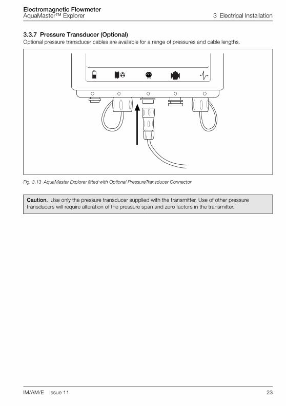
3.3.7 Pressure Transducer (Optional)Optional pressure transducer cables are available for a range of pressures and cable lengths.
Fig. 3.13 AquaMaster Explorer fitted with Optional PressureTransducer Connector
Caution. Use only the pressure transducer supplied with the transmitter. Use of other pressure transducers will require alteration of the pressure span and zero factors in the transmitter.

Electromagnetic FlowmeterAquaMaster™ Explorer 3 Electrical Installation
24 IM/AM/E Issue 11
3.3.8 Anti-tamper ProtectionIn some applications, such as those covered by the Measuring Instruments Directive (MID) 2004/22/EEC orOIML R49 the flowmeter can be sealed to prevent unauthorized changes to the instrument settings andconfiguration. A read-only switch/link is used (as detailed in Fig. 3.14) to prevent login through anycommunication means and modification of any parameters on the AquaMaster/Explorer.
Fig. 3.14 Read-only Switch Connections
A Pressure Sensor Bridge +
B Pressure Sensor Output +
C Pressure Sensor Bridge -
D Pressure Sensor Output -
E Read-Only Switch link
F Read-Only Switch link
To force the Explorer into read-only state, link connections E & F*
*ABB Supply a plug with this link fitted– part number WEBX0060
If a pressure transducer is required, an adapter cable (part number WEBC2025) can be used
D
AB F
EC
Electromagnetic FlowmeterAquaMaster™ Explorer 3 Electrical Installation
IM/AM/E Issue 11 25
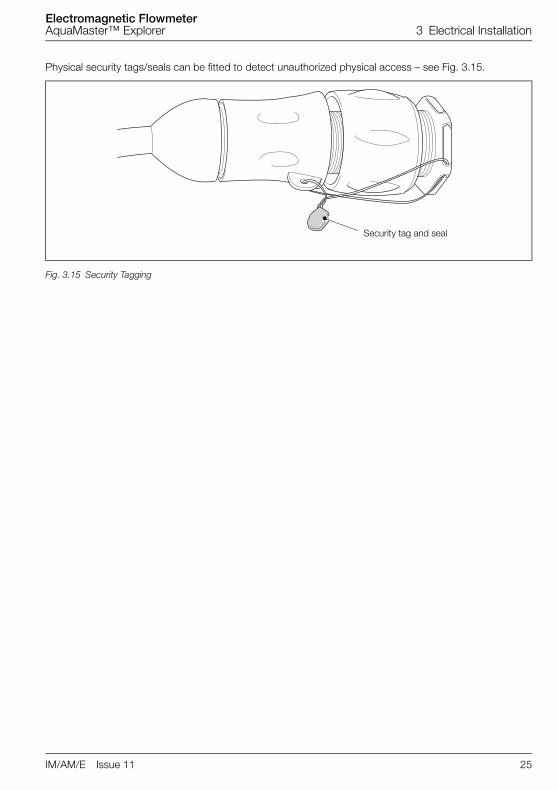
Physical security tags/seals can be fitted to detect unauthorized physical access – see Fig. 3.15.
Fig. 3.15 Security Tagging
Security tag and seal

Electromagnetic FlowmeterAquaMaster™ Explorer 4 Start-Up And Operation
26 IM/AM/E Issue 11
4 Start-Up And Operation
4.1 Connecting BatteriesAquaMaster can be supplied with an optional battery pack. Make connections as shown in Fig. 4.1.
Warning.
� The battery used in this device may present a risk of fire or chemical burns if mistreated. Do not recharge, disassemble, heat above 100 °C or incinerate.
� Replace battery pack with an ABB supplied part only. Use of another battery may present a risk of fire or explosion.
� Dispose of all battery packs promptly. Keep away from children.
� Dispose of battery packs in accordance with local regulations.
� Where possible, recycle used batteries.
� Contact the local environmental authority for further information regarding disposal or recycling schemes for used batteries.
� Operation at elevated temperatures (>45 °C) will significantly shorten the battery capacity and life.
Fig. 4.1 Connecting Batteries – AquaMaster Explorer

Electromagnetic FlowmeterAquaMaster™ Explorer 4 Start-Up And Operation
IM/AM/E Issue 11 27
4.2 Start-upRemove any plastic film from the AquaMaster light sensitive display window before commencing normaloperation.
When electrical power is connected, or the plastic film is removed from the display window with electricalpower connected, the AquaMaster performs a self-test operation. If successful, 'Pass' is indicated in thedisplay window.
If the display shows 'Err 1', check the sensor wiring. If the fault is rectified, the transmitter restartsautomatically.
If the display shows 'Err 2 or 3', contact ABB.
4.3 Display ActivationFor normal operation, activate the light sensitive display by first covering the display area totally.
On removing the covering, the display activates and cycles through the programmed set of displaymeasurements.
Fig. 4.2 Location of Controls
Note. For the use of local or remote serial communication and how to alter the displayed set of measurements, or instrument setup, see the Quick Reference Programming Guide.
Lower Display
Time
Flow Velocity
Pressure
Left Battery Warning
Sensor Fault
Empty Pipe condition
Mains Failure
Right Battery Warning
Upper Display
Date
Forward Flow Total
Reverse Flow Total
Net Flow Total
Pictorial Displays
Warning Annunciators

Electromagnetic FlowmeterAquaMaster™ Explorer 4 Start-Up And Operation
28 IM/AM/E Issue 11
4.4 Replacing a BatteryNormal Operation
If both batteries are good, no battery icons are displayed.
Replace Battery
When a single battery icon is shown, this indicates the mainbattery pack is exhausted and the transmitter is now runningon the battery pack reserve supply. The flowmeter is stillworking normally. The battery pack should now be changed.
Battery Pack Exhausted
Important. Both the main and reserve battery packs areexhausted and the flowmeter is no longer working. Replace thebattery pack.
Note. On transmitters fitted with built in data loggers, download any logger contents before changing the battery.

Electromagnetic FlowmeterAquaMaster™ Explorer 4 Start-Up And Operation
IM/AM/E Issue 11 29
4.5 Servicing Plugs and SocketsTo ensure long and reliable service life for the plugs and sockets on AquaMaster Explorer Flow Transmitters,ABB recommend regular treatment of the gold connector pins:
4.5.1 Service IntervalsTreat all connectors:
� at 3-year intervals
� when the battery is changed
� when the installation is visited for other reasons (such as CalMaster 2 Verification)
Fig. 4.3 Transmitter Sockets (Bulgin)
Fig. 4.4 Transmitter Sockets (MIL Style)
Connectors
Connectors

Electromagnetic FlowmeterAquaMaster™ Explorer 4 Start-Up And Operation
30 IM/AM/E Issue 11
4.5.2 Equipment RequiredCleaners are available from your local ABB representative. To purchase supplies directly or for localdistributor details please go to the following website:
http://store.caig.com/
Material details are:
4.5.3 Preparation
4.5.4 DisconnectionBefore DeoxIT treatment disconnect ALL cables in the following order:
1. Battery
2. Sensor
3. Pressure transducer (if fitted)
4. Outputs
5. Communications cable (if connected)
Uncap unused connectors.
Description Part No.
DeoxIT® – Contact Cleaner & RejuvenatorDeoxIT® – Mini-spray, 5 % solution, flushing action, 14g(Applications = 150 approx.)
D5MS–15
DeoxIT® GOLD – Contact Enhancer, conditioner & ProtectorDeoxIT® GOLD G5 Mini Spray 5 % solution, 14 g, flushing action and safe on plastics(Applications = 150 approx.)
G5MS–S
Item Precaution
Real-time Clock This procedure may result in the loss of the real-time clock.
Once the treatment is complete, check and if necessary, re-program the real-time clock and date – see section 4.5.6, page 32.
Transmitters with Data Loggers
This procedure may result in the loss of logger contents on transmitters fitted with data loggers.
To prevent data loss, download logger data before treating the connector pins.
Electromagnetic FlowmeterAquaMaster™ Explorer 4 Start-Up And Operation
IM/AM/E Issue 11 31
4.5.5 Order of TreatmentTo minimise disruptive effects of repeatedly breaking and making connections the following order oftreatment should be followed using the Stage1 and Stage2 processes for each plug and socket in turn:
1. Treat sensor connector & cable (ensure battery is disconnected at this point).
2. Disconnect sensor cable.
3. Treat battery connector & cable (ensure sensor is disconnected at this point).
4. Disconnect battery cable.
5. Treat all other peripheral connections and cables.
6. Ensure all cables are disconnected.
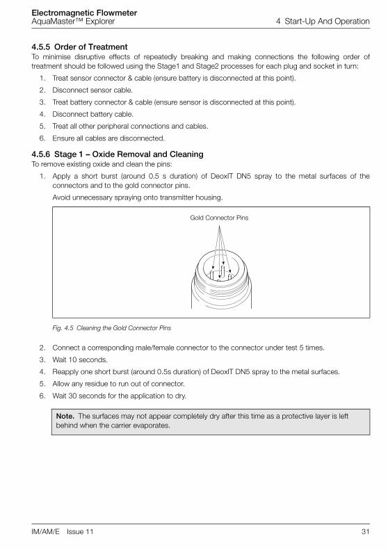
4.5.6 Stage 1 – Oxide Removal and CleaningTo remove existing oxide and clean the pins:
1. Apply a short burst (around 0.5 s duration) of DeoxIT DN5 spray to the metal surfaces of theconnectors and to the gold connector pins.
Avoid unnecessary spraying onto transmitter housing.
2. Connect a corresponding male/female connector to the connector under test 5 times.
3. Wait 10 seconds.
4. Reapply one short burst (around 0.5s duration) of DeoxIT DN5 spray to the metal surfaces.
5. Allow any residue to run out of connector.
6. Wait 30 seconds for the application to dry.
Fig. 4.5 Cleaning the Gold Connector Pins
Note. The surfaces may not appear completely dry after this time as a protective layer is left behind when the carrier evaporates.
Gold Connector Pins

Electromagnetic FlowmeterAquaMaster™ Explorer 4 Start-Up And Operation
32 IM/AM/E Issue 11
4.5.7 Stage 2 – Oxide PreventionTo prevent oxide build-up:
1. Apply a very short burst (not more than 0.5s duration) of DeoxIT Gold GN5 spray to the metalsurfaces.
Avoid unnecessary spraying onto transmitter housing.
2. Wait 10 seconds.
3. Reapply one very short burst (not more than 0.5s duration) of DeoxIT Gold GN5 spray to the metalsurfaces.
4. Allow any residue to run out of connector.
5. Wait 30 seconds for the application to dry.
4.5.8 Completion TasksTo complete servicing of the plugs and sockets:
1. Reconnect peripheral devices in this order.
a. Sensor
b. Pressure transducer (if fitted)
c. Outputs
d. Battery
2. Refit protective caps on unused connection sockets.
3. For transmitters with built-in loggers and no GSM, re-program the real-time clock and date – seeProgramming Manual IM/AMS/QRG).
Note. The surfaces may not appear completely dry after this time as a protective layer is left behind when the carrier evaporates.

Electromagnetic FlowmeterAquaMaster™ Explorer 4 Start-Up And Operation
IM/AM/E Issue 11 33
4.6 Accessories/Spares KitsCommon
MRBX9969 Close Coupled Mounting KitWEBC2000 AquaMaster Local Comms AdaptorWEBC2003/01 Remote GSM Aerial Kit 1mWEBC2003/05 Remote GSM Aerial Kit 5m
Bulgin Connector
WABC2017 Remote Battery PackWABC2020 Sensor Cable Assy 0.5 m, for integral / close-coupledWABC2020/01 Sensor Cable Assy 1 m, for remote WABC2020/03 Sensor Cable Assy 3 m, for remote WABC2020/10 Sensor Cable Assy 10 m, for remote WABC2020/20 Sensor Cable Assy 20 m, for remoteWABC2020/30 Sensor Cable Assy 30 m, for remoteWABC2020/40 Sensor Cable Assy 40 m, for remoteWABC2020/50 Sensor Cable Assy 50 m, for remoteWABC2020/60 Sensor Cable Assy 60 m, for remoteWABC2020/70 Sensor Cable Assy 70 m, for remoteWABC2020/80 Sensor Cable Assy 80 m, for remoteWABC2020/01 Output Cable 1m wire-endedWEBC2011 Output Cable for Technolog Cello (MIL)WEBC2012 Output Cable for Technolog Cello (Brad Harrsion)WEBC2013 Output Cable for RADCOM MultilogWEBC2014 Output Cable for Primayer XilogWEBC2005 Output Cable to 19way MILWEBC2006 Output Cable to 2x19way MILWEBC2007 Output Cable to 7way MIL & Technolog CelloWEBC2004 Connector Security Locking Ring – pack of 5WABX2010/05 Pressure Cable Assy 16bar, 5mWABX2010/10 Pressure Cable Assy 16bar, 10mWEBC2010/05 Scanreader cable 5mWEBC2010/10 Scanreader cable 10mWEBC2010/20 Scanreader cable 20mWEBC2010/30 Scanreader cable 30m

Electromagnetic FlowmeterAquaMaster™ Explorer 4 Start-Up And Operation
34 IM/AM/E Issue 11
MIL Style Connector
WABC2033 Remote Battery PackWABC2010 Sensor Cable Assy 0.5 m, for integral / close-coupled WABC2010/01 Sensor Cable Assy 1 m, for remote WABC2010/03 Sensor Cable Assy 3 m, for remote WABC2010/10 Sensor Cable Assy 10 m, for remote WABC2010/20 Sensor Cable Assy 20 m, for remoteWABC2010/30 Sensor Cable Assy 30 m, for remoteWABC2010/40 Sensor Cable Assy 40 m, for remoteWABC2010/50 Sensor Cable Assy 50 m, for remoteWABC2010/60 Sensor Cable Assy 60 m, for remoteWABC2010/70 Sensor Cable Assy 70 m, for remoteWABC2010/80 Sensor Cable Assy 80 m, for remoteWABC2010/01 Output Cable 1m wire-ended
WEBC2011/M Output Cable for Technolog Cello (MIL)
WEBC2012/M Output Cable for Technolog Cello (Brad Harrsion)WEBC2013/M Output Cable for RADCOM MultilogWEBC2014/M Output Cable for Primayer XilogWEBC2006/M Output Cable 2x19way MILWEBC2024 Connector Security Plug – pack of 5WABX2000/05 Pressure Cable Assy 16bar, 5mWABX2000/10 Pressure Cable Assy 16bar, 10m
Adapter Cable/Upgrade Kits – Bulgin Connector
WABC2029 Sensor Adapter Kit (Compact M20 Plastic to Bulgin)WEBC2001 Sensor MIL Cable adapter (MIL to Bulgin)WEBC2002 Pressure MIL Cable adapter (MIL to Bulgin)WABC2022/B Sensor Upgrade Kit (M20 Plastic to Bulgin)WABC2023/B Sensor Upgrade Kit (M20 Armoured to Bulgin)WABC2024/B Sensor Adaptor Kit (M20 Plastic to Bulgin)WABC2025/B Sensor Adaptor Kit (M20 Armoured to Bulgin)WABC2026/B Sensor Adaptor Kit (½NPT blanked to Bulgin)
Adapter Cable/Upgrade Kits – MIL Style Connector
WABC2035 Sensor Adapter Kit (M16 Plastic to MIL)WABC2036 Pressure Adapter Kit (M16 Plastic to MIL)WABC2022/M Sensor Upgrade Kit (M20 Plastic to MIL)WABC2023/M Sensor Upgrade Kit (M20 Armoured to MIL)WABC2024/M Sensor Adaptor Kit (M20 Plastic to MIL)WABC2025/M Sensor Adaptor Kit (M20 Armoured to MIL)WABC2026/M Sensor Adaptor Kit (½NPT blanked to Bulgin)

Electromagnetic FlowmeterAquaMaster™ Explorer 5 Specification
IM/AM/E Issue 11 35
5 Specification
Battery-powered Meters – Flow Requirements to OIML R49
AquaMaster OIMLClass 2 Specification
AquaMaster OIML Class 1 Specification
Size Q4 Q3 Q(0.5%) Q2 Q1 R Q2 Q1 R
mm in. m3 / h (Ugal/min)
m3 / h (Ugal/ min)
m3 / h (Ugal/ min)
m3 / h (Ugal/min)
m3 / h (Ugal/min)
m3 / h (Ugal/ min)
m3 / h (Ugal/min)
15 1/2 5 (22) 4 (18) 0.24 (1.05) 0.026 (0.110) 0.016 (0.070) 250 0.04 (0.176) 0.025 (0.11) 160
20 3/4 7.9 (34.8) 6.3 (28) 0.37 (1.62) 0.04 (0.176) 0.025 (0.110) 250 0.063 (0.277)
0.04 (0.176) 160
25 1 12.5 (55) 10 (44) 0.6 (2.64) 0.064 (0.281) 0.04 (0.176) 250 0.1 (0.44) 0.063 (0.277)
160
40* 11/2 31 (138) 25 (110) 1.5 (6.6) 0.16 (0.704) 0.1 (0.44) 250 0.25 (1.10) 0.16 (0.704) 160
50* 2 50 (220) 40 (176) 2.4 (10.56) 0.26 (1.14) 0.16 (0.70) 250 0.4 (1.76) 0.25 (1.10) 160
65 21/2 79 (347) 63 (277) 3.7 (16.29) 0.40 (1.76) 0.25 (1.10) 250 0.63 (2.77) 0.4 (1.76) 160
80* 3 125 (550) 100 (440) 5.9 (25.97) 0.64 (2.81) 0.4 (1.76) 250 1 (4.40) 0.63 (2.77) 160
100* 4 200 (880) 160 (700) 9.4 (41.38) 1.0 (4.4) 0.64 (2.81) 250 1.6 (7.04) 1 (4.40) 160
125 5 313 (1378) 250 (1100) 14.7 (64.72)
1.6 (7.04) 1.0 (4.4) 250 2.5 (11) 1.6 (7.04) 160
150* 6 500 (2200) 400 (1760) 23.5 (103.46)
2.56 (11.27) 1.6 (7.04) 250 4 (17.61) 2.5 (11) 160
200* 8 788 (3470) 630 (2770) 37 (162.90) 4.0 (17.61) 2.5 (8.8) 250 6.3 (27.73) 3.9 (17.17) 160
250* 10 1250 (5500) 1000 (4400) 60 (260) 6.4 (28.18) 4 (17.6) 250 10 (44) 6.3 (27.73) 160
300* 12 2000 (8810) 1600 (7040) 90 (400) 10.2 (44.91) 6.4 (28.18) 250 16 (70.44) 10 (44) 160
350 14 2000 (8810) 1600 (7040) 110 (484.3) 16 (70.44) 10 (44.02) 160 41 (180.5) 25 (110) 63
400 16 3125 (13760) 2500 (11010)
170 (748.48) 25 (110) 15.6 (68.68) 160 63 (277.4) 40 (176) 63
450 18 3125 (13760) 2500 (11007)
170 (748.48) 25 (110) 15.6 (68.68) 160 63 (277.4) 40 (176) 63
500 20 5000 (22010) 4000 (17610)
270 (1188.72)
40 (176.11) 25 (110) 160 100 (440.3) 63.5 (279.6) 63
600 24 7875 (34670) 6300 (27740)
420 (1849.20)
63 (277.38) 39 (171.71) 160 160 (704.4) 100 (440.3) 63
* OIML R49 version available to Class 1 and Class 2
Note. OIML R49–1 allow Class 1 only for meters with Q3 ≥ 100 m3/h. Meters outside this range have been testedand conform to Class 1 specification.

Electromagnetic FlowmeterAquaMaster™ Explorer 5 Specification
36 IM/AM/E Issue 11
Wetted MaterialsScrew-end meters
BrassFlanged meters
Electrodes – stainless steel 316LLining
Suitable for potable water (WRAS listed), ACS (except DN65)Pressure limitations
As flange ratingPN25 Max Process Temp 50 °CPN40 Max Process Temp 40 °COIML / MID Approved Meters 16 bar
Pressure equipment directive 97/23/ECThis product is applicable in networks for the supply, distribution and discharge of water and associated equipment andis therefore exempt.
Conductivity>50 µS/cm
End Connections
Thread-end connections15 mm – G 3/4 in B 3/4 in NPSM
20 mm – G 1 in B 1 in NPSM
25 mm – G 11/4 in B 11/4 in NPSM
40 to 300 mm (1.5 to 12 in) flangedEN1092-1 / ISO 7005 – PN10, PN16, PN25
ANSI B16.5 Class 150
AS 2129 Tables C, D, E and F
AS 4087 PN14, PN16, PN21
JIS to BS2210, 10k
350 to 600 mm (14 to 24 in) flangedEN1092-1 / ISO 7005 – PN10, PN16, PN25
AS 4087 PN14, PN16, PN21
AS 2129 Tables C, D, E and F
ANSI B16.5 Class 150
JIS to B2210 5k and 10k
OIML R49 ApprovalSize range and flow specification
See specification tableAccuracy class
1 and 2Environmental class
T50 0.1 °C to 50 °C (32.18 °F to 122 °F)Pressure loss class
< 0.63 barMinimum upstream pipe
0 D

Electromagnetic FlowmeterAquaMaster™ Explorer 5 Specification
IM/AM/E Issue 11 37
Minimum downstream pipe0 D
OrientationAny
MID ApprovalApproved to directive 2004/22/EC
Explorer Transmitter
MountingDirectly on sensor
or
Remote up to 200 m (650 ft)
HousingIP68 (NEMA 6P)
Stainless steel housing in a Thermoplastic outer cover with window, encapsulated with polyurethane-based resin.
Electrical connectionsIP68 plug & socket
Sensor cableABB cable supplied as standard
SWA cable available (via adaptor box) on application
External battery packIP68 (NEMA 6P)
Battery life @ 0 to 45 °C (32 to 113 °F) typically 5 years
Extended life is possible to give, say, 6 years with a small degradation in response time and slightly increasedmeasurement uncertainty (contact ABB for details).
Battery life is shorter with GSM, depending on how frequently it is used and for what period. For example, used onceper day for SMS automated reporting of data logged at 15 minute intervals, the life of a battery pack would be typicallyreduced to approximately 4 years.
Pulse and alarm outputsThree bidirectional solid state switches with common isolation
±35 V DC 50mA
Output 1 Forward only, or forward plus reverse pulses
Output 2 Reverse pulses, or direction indicator
Output 3 Alarm indicates any problem with measurement or with power
Pulse output 50 Hz maximum, 50 % nominal duty cycle
Serial data communicationsLocal Port RS232 compatible via ABB lead (Option)

Electromagnetic FlowmeterAquaMaster™ Explorer 5 Specification
38 IM/AM/E Issue 11
Encoder Interface (non-logging versions only)
FunctionRemote reading of totalizer and serial no.
ProtocolABB encoder
Connections2-wire for inductive pads (max. cable length 80 m [260 ft])
3-wire for AMR
Compatible readersSevern Trent Services Smart reader
ABB or Elster SR100 and SR50
Logicon Versaprobe
Itron ERT
Compatible inductive padsStarpad
ABB
Telemetry applications using remote serial data communicationsInternal GSM modem Dual Band GSM; fully programmable schedule for battery operation and Automated MeterReading
Pressure System – External Transducer
Pressure range16 bar Abs.
ConnectionStandard quick-fit male probe connector via an adapter cable
Operating temperature range–20 (ambient) to 70 °C (–4 to 158 °F)
Accuracy (typical)±0.4 % of range
Thermal error band (typically 100 °C [212 °F])±1.5 % span
Cable length5 or 10 m (16 or 33 ft)
Caution. Protect the sample and transducer from freezing.

Electromagnetic FlowmeterAquaMaster™ Explorer 5 Specification
IM/AM/E Issue 11 39
Temperature Ranges
Response Time (Programmable)
Minimum1 s (mains-powered)
15 s (battery-powered)
LanguagesEnglish
French
German
Spanish
Italian
Dutch
Note. Operation outside ambient temperature limits of 0 to 45 °C (32 to 113 °F) reduces battery capacity and shortens battery life.
Process Ambient Storage
70 °C (158 °F)70 °C (158 °F)60 °C (140 °F)
–30 °C (–22 °F)–20 °C (–4 °F)–10 °C (14 °F)

Electromagnetic FlowmeterAquaMaster™ Explorer 5 Specification
40 IM/AM/E Issue 11
Mounting
Pipe Conditions
Pressure Loss
Flow Rate Pressure Loss in bar (psi)
Q3 <0.63 (9.1)
Q3/2 <0.16 (2.3)
Sensor Electrodes
45 ° Maximum
0 x pipe dia.
minimum
0 x pipe dia.
minimum
Flow Direction

Electromagnetic FlowmeterAquaMaster™ Explorer 5 Specification
IM/AM/E Issue 11 41
Logger details (option)
GSM Antenna (option)
MountingIntegral with transmitter or remote.
Antenna environmentalIP66 (NEMA4) waterproof for accidental submersion
(Note. The GSM does not operate with integral antenna under water).
General advice is to mount the antenna as high as possible, always outside of any metal enclosure and not under thesurface of the ground.
Logger
1 2 3
Logger Function Flow & Pressure Flow & Pressure Forward, Reverse, Tariffs & Net Flow Totals
No. of Records 8831 11361 366
Logging Interval 15 to 65500 s (adjustable) 24 hr (fixed)
Typical Capacity 3 months @15 min ~7 days @ 1 min 1 year
Mode Cyclic Cyclic Cyclic
Use ABB LogMaster
Use Technolog (PMAC)
Use Primayer Primeware
Use OSI PI Database / CBV (WADIS) System

Electromagnetic FlowmeterAquaMaster™ Explorer 5 Specification
42 IM/AM/E Issue 11
Default Settings Table
Sensor Specification (Nominal Dimensions)
15 to 25 mm (1/2 to 1 in.) – Screw Ends
Configuration Parameter Default European Default North American
Pulse Factor 1 1
Pulse Units m3 Ugal
Totalizer Units m3 Ugal
Full Scale Flow Q3 Q3
Flow Units m3 / h MUGD
Velocity Units m / s ft / s
Date Format from Country Code DDMMYY MMDDYY
Flow Response Time (s) 3 3
Display Flow Rate Yes Yes
Display Forward Total Yes Yes
Display Reverse Total Yes Yes
Display Net Total No No
Display Date No No
Display Velocity No No
Output Option Pulse Forward Pulses Forward Pulses Forward
Output Option Pulse Reverse Pulses Reverse Pulses Reverse
Profile Factor 1 1
Probe Insertion Factor 1 1
Meter Size Dimensionsmm (in.)
Approx. Weight
mm in. A Connection kg lb
15 1/2 119 (4.7) G 3/4 in. B or 3/4 in. NPSM 2.5 5
20 3/4 127 (5) G 1 in. B or 1 in. NPSM 2.5 5
25 1 127 (5) G 11/4 in. B or 11/4 in. NPSM 2.5 5

Electromagnetic FlowmeterAquaMaster™ Explorer 5 Specification
IM/AM/E Issue 11 43
40 to 300 mm (11/2 to 12 in.) – Flanged
Dimensions in. mm (in.)
Meter Size Dimensions mm (in.) Approx. Weight
mm in. A B kg lb
40 11/2 176 (7) 200 (7.9) 11 24
50 2 176 (7) 200 (7.9) 12 27
65 21/2 219 (8.6) 200 (7.9) 13 29
80 3 219 (8.6) 200 (7.9) 18 40
100 4 230.5 (9.8) 250 (9.8) 25 55
150 6 281 (11.8) 300 (11.8) 31 68
200 8 402 (15.8) 350 (13.8) 48 106
250 10 440 (17.3) 450 (17.7) 75 165
300 12 480 (18.9) 500 (19.7) 112 247
�
128 (5)
61 (2.4)
89 (3.5)
��
Electromagnetic FlowmeterAquaMaster™ Explorer 5 Specification
44 IM/AM/E Issue 11
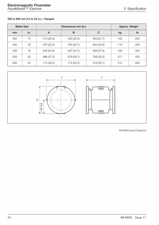
350 to 600 mm (14 to 24 in.) – Flanged
DS/AMAS Issue 6 (Explorer)
Meter Size Dimensions mm (in.) Approx. Weight
mm in. A B C kg lb
350 14 513 (20.2) 520 (20.5) 550 (21.7) 100 220
400 16 570 (22.4) 576 (22.7) 600 (23.6) 115 253
450 18 632 (24.9) 627 (24.7) 698 (27.5) 160 352
500 20 686 (27.0) 679 (26.7) 768 (30.2) 217 455
600 24 772 (30.4) 770 (30.3) 918 (36.1) 315 693
�
�
�
= 5
0 %
A

Electromagnetic FlowmeterAquaMaster™ Explorer Appendix A Hazardous Area Protection
IM/AM/E Issue 11 47
Appendix A Hazardous Area Protection
A.1 GSM-Equipped Units – Safety PrecautionsThe following safety precautions must be observed during all phases of the operation, usage, service orrepair of this GSM cellular terminal. Failure to comply with these precautions violates safety standards ofdesign, manufacture and intended use of the product. The Company assumes no liability for customerfailure to comply with these precautions.
1. When in a hospital or other health care facility, observe the restrictions on the use of mobiles. Switchthe cellular terminal or mobile off, if instructed to do so by the guidelines posted in sensitive areas.Medical equipment may be sensitive to RF energy. The operation of cardiac pacemakers, otherimplanted medical equipment and hearing aids can be affected by interference from cellular terminalsor mobiles placed close to the device. If in doubt about potential danger, contact the physician or themanufacturer of the device to verify that the equipment is properly shielded. Pacemaker patients areadvised to keep their hand-held mobile away from the pacemaker, while it is on.
2. Switch off the cellular terminal or mobile before boarding an aircraft. Make sure it cannot be switchedon inadvertently. The operation of wireless appliances in an aircraft is forbidden to preventinterference with communications systems. Failure to observe these instructions may lead to thesuspension or denial of cellular services to the offender, legal action, or both.
3. Do not operate the cellular terminal or mobile in the presence of flammable gases or fumes. Switchoff the cellular terminal when you are near petrol stations, fuel depots, chemical plants or whereblasting operations are in progress. Operation of any electrical equipment in potentially explosiveatmospheres can constitute a safety hazard.
4. Your cellular terminal or mobile receives and transmits radio frequency energy while switched on.Remember that interference can occur if it is used close to TV sets, radios, computers orinadequately shielded equipment. Follow any special regulations and always switch off the cellularterminal or mobile wherever forbidden, or when you suspect that it may cause interference ordanger.
Remember, in order to make or receive calls, the cellular terminal or mobile must be switched on and in aservice area with adequate cellular signal strength.
Note. Cellular terminals or mobiles operate using radio signals and cellular networks cannot be guaranteed to connect in all conditions. Therefore, you should never rely solely upon any wireless device for essential communications, for example emergency calls.

Electromagnetic FlowmeterAquaMaster™ Explorer Appendix A Hazardous Area Protection
48 IM/AM/E Issue 11
Fig.
A.1
Aqu
aMas
ter
Blo
ck D
iagr
am
� � � � � �
� � � � � �
Mea
sure
men
t
Sys
tem
Pre
ssur
eTr
ansd
ucer
Pro
cess
or
Dis
play
Par
t No.
WEB
C20
00
Loca
l Con
figur
atio
n A
dapt
or
Com
mon
Pul
se/A
larm
C
ircui
tsOpt
iona
lG
SM
Mod
em
Tran
smitt
er
Sen
sor

Electromagnetic FlowmeterAquaMaster™ Explorer Notes
IM/AM/E Issue 11 47
Notes

Electromagnetic FlowmeterAquaMaster™ Explorer Notes
48 IM/AM/E Issue 11

PRODUCTS & CUSTOMER SUPPORTProducts
Automation Systems• for the following industries:
– Chemical & Pharmaceutical– Food & Beverage– Manufacturing– Metals and Minerals– Oil, Gas & Petrochemical– Pulp and Paper
Drives and Motors• AC and DC Drives, AC and DC Machines,
AC Motors to 1kV• Drive Systems• Force Measurement• Servo Drives
Controllers & Recorders• Single and Multi-loop Controllers• Circular Chart and Strip Chart Recorders• Paperless Recorders• Process Indicators
Flexible Automation• Industrial Robots and Robot Systems
Flow Measurement• Electromagnetic Flowmeters• Mass Flowmeters• Turbine Flowmeters• Wedge Flow Elements
Marine Systems & Turbochargers• Electrical Systems• Marine Equipment• Offshore Retrofit and Refurbishment
Process Analytics• Process Gas Analysis• Systems Integration
Transmitters• Pressure• Temperature• Level• Interface Modules
Valves, Actuators and Positioners• Control Valves• Actuators• Positioners
Water, Gas & Industrial Analytics Instrumentation
• pH, Conductivity and Dissolved Oxygen Transmitters and Sensors
• Ammonia, Nitrate, Phosphate, Silica, Sodium, Chloride, Fluoride, Dissolved Oxygen and Hydrazine Analyzers
• Zirconia Oxygen Analyzers, Katharometers, Hydrogen Purity and Purge-gas Monitors, Thermal Conductivity
Customer Support
We provide a comprehensive after sales service via aWorldwide Service Organization. Contact one of thefollowing offices for details on your nearest Service andRepair Centre.
UKABB LimitedTel: +44 (0)1453 826661Fax: +44 (0)1453 829671
USAABB Inc.Tel: +1 215 674 6000Fax: +1 215 674 7183
Client WarrantyPrior to installation, the equipment referred to in thismanual must be stored in a clean, dry environment, inaccordance with the Company's publishedspecification.
Periodic checks must be made on the equipment'scondition. In the event of a failure under warranty, thefollowing documentation must be provided assubstantiation:
1. A listing evidencing process operation and alarm logs at time of failure.
2. Copies of all storage, installation, operating and maintenance records relating to the alleged faulty unit.

IM/A
M/E
Issu
e 11
ABB has Sales & Customer Support expertisein over 100 countries worldwide
www.abb.com
The Company’s policy is one of continuous product improvement and the right is reserved to modify the
information contained herein without notice.
Printed in UK (05.10)
© ABB 2010
ABB LimitedOldends Lane, StonehouseGloucestershireGL10 3TAUKTel: +44 (0)1453 826661Fax: +44 (0)1453 829671
ABB Inc.125 E. County Line RoadWarminsterPA 18974USATel:+1 215 674 6000Fax:+1 215 674 7183


![User´s AXFA14G/C Manual Magnetic Flowmeter Remote ... · AXFA14G/C Magnetic Flowmeter Remote Converter [Hardware Edition/Software Edition] AXF Magnetic Flowmeter Integral Flowmeter](https://img.pdfslide.us/doc/110x75/5e9c29ae5a06915e2b2224e0/users-axfa14gc-manual-magnetic-flowmeter-remote-axfa14gc-magnetic-flowmeter.jpg)

![AXR Two-wire Magnetic Flowmeter Integral Flowmeter [Style:S2]User’s Manual AXR Two-wire Magnetic Flowmeter Integral Flowmeter [Style:S2] IM 01E30D01-01EN IM 01E30D01-01EN 8th Edition](https://img.pdfslide.us/doc/110x75/6030690230362b13964fde5e/axr-two-wire-magnetic-flowmeter-integral-flowmeter-styles2-useras-manual-axr.jpg)


![AXR Two-wire Magnetic Flowmeter Integral Flowmeter [Style:S2]](https://img.pdfslide.us/doc/110x75/62cb14e07ee31d38b74d3e5b/axr-two-wire-magnetic-flowmeter-integral-flowmeter-styles2.jpg)