Embed Size (px)
Citation preview

X7503205901 X75000986112/08
Chain SawInstruction Manual
MODEL CS-306
WARNINGRead rules for safe operation and instructions carefully. ECHO provides an Instruc-tion Manual and a Safety Manual. Both must be read and understood for proper andsafe operation.

2
RULES FOR SAFE OPERATIONA. Kickback Safety Precaution for Chain Saw Users
WARNING!KICKBACK may occur when the nose or tip of theguide bar touches an object, or when the woodcloses in and pinches the saw chain in the cut.
Tip contact in some cases may cause a lightningfast reverse REACTION, Kicking the guide bar upand back towards the operator. Pinching the sawchain along the top of the guide bar may push theguide bar rapidly back towards the operator. Ei-ther of these reactions may cause you to losecontrol of the saw which could result in seriouspersonal injury.
The Kick Guard ® device is not installed on theguide bar when you purchase your ECHO chainsaw. The Kick Guard ® can be used in a majorityof cutting operations, and is especially recom-mended for beginners, homeowners, or chain sawnovices. Most cutting operations can be accom-plished with the Kick Guard® in place.
Do not rely exclusively upon the safety devicesbuilt into your saw. As a chain saw user, you shouldtake several steps to keep your cutting jobs freefrom accident or injury.
1. With a basic understanding of kickback, youcan reduce or eliminate the element of sur-prise. Sudden surprise contributes to acci-dents.
2. Keep a good firm grip on the saw with bothhands, the right hand on the rear handle, andthe left hand on the front handle, when theengine is running. Use a firm grip with thumbsand fingers encircling the chain saw handles.A firm grip will help you reduce kickback andmaintain control of the saw. Don’t’ let go.
3. Make sure that the area in which you are cut-ting is free from obstructions. Do not let thenose of the guide bar contact a log, branch, orany other obstruction which could be hit whileyou are operating the saw.
4. Cut at high engine speeds.
5. Do not overreach or cut above shoulder height.
6. Follow manufacturer’s sharpening and main-tenance instructions for the saw chain.
7. Only use replacement bars and chains speci-fied by the manufacturer or the equivalent.
B. Other Safety Precautions
1. Do not operate a chain saw with one hand!Serious injury to the operator, helpers, by-standers, or any combination of these per-sons may result from one-handed operation.A chain saw is intended for two-handed use.
2. Do not operate a chain saw when you arefatigued.
3. Use safety footwear; snug-fitting clothing; pro-tective gloves; and eye, hearing and head pro-tection devices. Keep long hair away fromengine and air intake. Retain hair with cap ornet.
4. Use caution when handling fuel. Move the chainsaw at least 3 m (10 feet) from the fuelingpoint before starting the engine.
5. Do not allow other persons to be near the chainsaw when starting or cutting with the chainsaw. Keep bystanders and animals out of thework area.
6. Do not start cutting until you have a clear workarea, secure footing, and a planned retreatpath from the falling tree.
Copyright© 2008 By Echo, IncorporatedAll Rights Reserved.

3
7. Keep all parts of your body away from thesaw chain when the engine is running.
8. Before you start the engine, make sure thatthe saw chain is not contacting anything.
9. Carry the chain saw with the engine stopped,the guide bar and saw chain to the rear, andthe muffler away from your body.
10.Do not operate a chain saw that is damaged,improperly adjusted, or not completely andsecurely assembled. Be sure that the sawchain stops moving when the throttle controltrigger is released.
11. Shut off the engine before setting the chainsaw down.
12.Use extreme caution when cutting small sizebrush and saplings because slender materialmay catch the saw chain and be whipped to-ward you or pull you off balance.
13.When cutting a limb that is under tension, bealert for spring back so that you will not bestruck when the tension in the wood fibers isreleased.
14.Keep the handles dry, clean, and free of oil orfuel mixture.
15.Operate the chain saw only in well-ventilatedareas.
16.Do not operate a chain saw in a tree unlessyou have been specifically trained to do so.
17.All chain saw service, other than the itemslisted in the Instruction Manual maintenanceinstructions, should be performed by compe-tent chain saw service personnel. (For ex-ample, if improper tools are used to removethe flywheel or if an improper tool is used tohold the flywheel in order to remove the clutch,structural damage to the flywheel could occurand could subsequently cause the flywheel toburst.)
18.When transporting your chain saw, use theappropriate guide bar scabbard.
19.Spark arrestor mufflers approved to SAE Stan-dard J335b are Standard on ECHO Chainsaws to reduce the possibility of forest fires.Do not operate the chain saw with a loose ordefective muffler. Do not remove the sparkarrestor screen.
WARNING• During operation, the muffler or catalytic muffler and surrounding cover become hot.• Never suspend the saw on a lanyard with the engine running.• Always use the saw from the right-hand side of your body – NEVER from the left side.• Always wear proper safety clothing to protect your lower body from sharp saw chain and
hot muffler.• Always keep exhaust area clear of flammable debris during transportation or when storing,
otherwise serious property damage or personal injury may result.
WARNINGUsing improper replacement components or removing safety devices may result in serious or fatal injury.
WARNINGCheck fuel system for leaks due to fuel tank damage, especially if the unit is dropped. If damage or leaks are found, do notuse unit, otherwise serious personal injury or property damage may occur. Have unit repaired by an authorized servicingdealer before using.
4
CONTENTS Page
Rules for Safe Operation ................................................................................................. 2Technical Data ................................................................................................................. 5Emission Data .................................................................................................................. 6Description ....................................................................................................................... 6Nomenclature of Parts ..................................................................................................... 7Preparation for Use ......................................................................................................... 8Fuel and Lubricant ........................................................................................................... 9Operation....................................................................................................................... 11Cutting Instructions ........................................................................................................ 14Maintenance and Care ................................................................................................... 17Chain and Guide Bar Combinations ............................................................................... 22Troubleshooting ............................................................................................................. 24Storage .......................................................................................................................... 26Correct Use of Chain Brake ........................................................................................... 26Servicing Information ..................................................................................................... 28
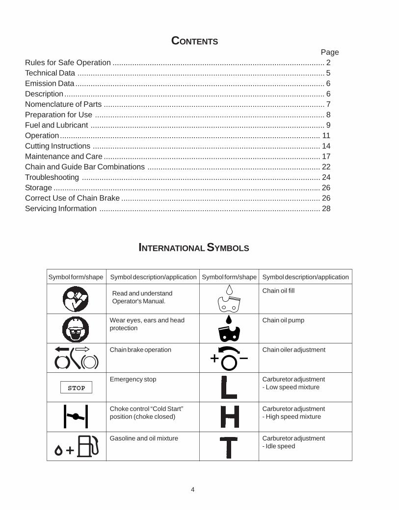
INTERNATIONAL SYMBOLS
Carburetor adjustment- Idle speed
Carburetor adjustment- High speed mixture
Wear eyes, ears and headprotection
Carburetor adjustment- Low speed mixture
Gasoline and oil mixture
Symbol form/shape Symbol description/application Symbol form/shape Symbol description/application
Chain oiler adjustmentChain brake operation
Chain oil pump
Chain oil fill
Emergency stop
Choke control “Cold Start”position (choke closed)
STOP
Read and understandOperator's Manual.
5
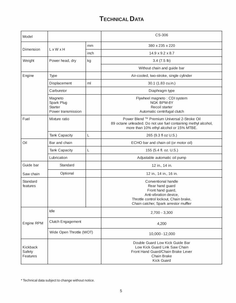
TECHNICAL DATA
* Technical data subject to change without notice.
ledoM 603-SC
noisnemiD HxWxLmm 022x532x083
hcni 7.8x2.9x9.41
thgieW yrd,daehrewoP gk )bl5.7(4.3
rabediugdnaniahctuohtiW
enignE epyT rednilycelgnis,ekorts-owt,delooc-riA
tnemecalpsiD lm ).ni.uc38.1(1.03
roterubraC epytmgarhpaiD
otengaMgulPkrapS
retratSnoissimsnartrewoP
metsysIDC:otengamleehwylFY8-MPBKGNretratslioceR
hctulclagufirtneccitamotuA
leuF oitarerutxiM dnelBrewoP MT liOekortS-2lasrevinUmuimerP,lohoclalyhtemgniniatnocleufesutonoD.dedaelnuenatco98
.EBTM%51rolohoclalyhte%01nahterom
yticapaCknaT L ).S.Uzolf3.9(562
liO niahcdnaraB )liorotomro(lioniahcdnarabOHCE
yticapaCknaT L ).S.U.zo.lf4.5(551
noitacirbuL pmupliocitamotuaelbatsujdA
rabediuG
niahcwaS
dradnatS .ni41,.ni21
lanoitpO .ni61,.ni41,.ni21
dradnatSserutaef
eldnahlanoitnevnoCdraugdnahraeR,draugdnahtnorF
,ecivednoitarbiv-itnA,ekarbniahC,tuokcollortnocelttorhTrelffumrotserrakrapS,rehctacniahC
MPRenignE
eldI 003,3-007,2
tnemegagnEhctulC 005,4-009,3
)TOW(elttorhTnepOediW 005,21-000,21
kcabkciKytefaS
serutaeF
raBediuGkciKwoLdrauGelbuoDniahCwaSkniLdrauGkciKwoL
reveLekarBniahC/drauGdnaHtnorFekarBniahC
drauGkciK
4,200
10,000 - 12,000

6
CS-306
EMISSION DATA
DESCRIPTION
The ECHO product you purchased has been factory pre-assembled for your convenience. Due to packagingrestrictions, guide bar and saw chain installation and other assembly may be necessary.
After opening the carton, check for damage. Immediately notify your retailer or ECHO Dealer of damaged ormissing parts. Use the contents list to check for missing parts.
CONTENTS1 - Power Head1 - Guide Bar1 - Kick Guard1 - Hex Head Bolt1 - Hex Nut1 - Saw Chain1 - Instruction Manual1 - Safety Manual1 - Warranty Registration Card1 - Limited Warranty Statement1 - T-Wrench1 - Echo Power BlendX TM 2-stroke oil sample
An Emission Control Label is located on the engine. (These are EXAMPLES ONLY, information on labelvaries by engine FAMILY).
IMPORTANT ENGINE INFORMATIONENGINE FAMILY: 8EXHS.0334CA DISPLACEMENT: 30.1 CC
EMISSION COMPLIANCE PERIOD: 300 HOURS
THIS ENGINE MEETS U.S. EPA PH2 EXH AND 2007 AND
LATER CALIFORNIA EXH AND EVAP EMISSION
REGULATIONS FOR S.O.R.E. REFER TO OWNER'S
MANUAL FOR MAINTENANCE SPECIFICATIONS AND
ADJUSTMENTS.
PRODUCT EMISSION DURABILITY (EMISSION COMPLIANCE PERIOD)The 300 hour emission compliance period is the time span selected by the manufacturer certifying the engineemissions output meets applicable emissions regulations, provided that approved maintenance procedures arefollowed as listed in the Maintenance Section of this manual.
EMISSION CONTROL (EXHAUST &EVAPORATIVE)
EPA Phase 2 / C.A.R.B. TIER IIIThe emission control system for the engine is EM/TWC(Engine Modification and 3-way Catalyst) and for the fueltank the Control System is EVAP (Evaporative Emissions)or N (for nylon tank). Evaporative emission may beapplicable to California models only.

7
15
WARNING ! !Read and fol low all safety precautions in theInstruct ion manual. Fai lure to fol low instruc-
t ions could result in serious personal injury.CHAIN SAW 87G1
IN ACCORDANCE WITHAMERICAN NATIONAL
STANDARD SAFETYREQUIREMENTS FOR
GASOLINE POWEREDCHAIN SAWS
(ANSI B175.1-2000)
NOMENCLATURE OF PARTS
11
12
1. Front handle
2. Hand guard
(Chain brake actuating lever)
3. Saw chain
4. Guide bar
5. Chain catcher
6. Sprocket guard
7. Muffler
8. Rear hand guard
9. Throttle control lockout
10. Throttle control trigger
11. Air cleaner cover
12. Chain tension adjustment screw
13. Pull starter
14. Throttle control latch
15. On / Off switch
16. Oil tank cap
17. Fuel tank cap
18. Purge bulb
19. Kick guard
20. Spark Plug
21. Guide Bar Nuts
22. Rear Handle
23. Choke
CS-306
14
16
17
1813
19
P/N X505002310 TO AVOID KICKBACK1. Hold the chain saw firmly with both
hands.2. Don’t let the nose of the guide bar
contact any obstruction.3. Tip contact may suddenly move the
guide bar upward and backward, whichmay cause serious injury.
P/N 89019130131
ADVERTENCIA PELIGRO
P/N 89022839131
Esta unidad puede ser peligrosa y producir lesionespersonales graves si no se usa en forma adecuada.Para reducir el riesgo de lesioarse, los operadores, los
ayudantes y los espectadores deben leer y comprender el ManualDel Operador y los Manuales De Seguridad que se entregan escritosen español.
REPLACEMENT BAR AND CHAIN
Note:There may be other replace-ment components for achievingkickback protection. For details,please refer to the chain and barcombination sheet shown in theinstruction manual.
P/N X524001691GUIDE BAR* CHAIN*
PART NO. TYPE LINKS12” 12A4CD3745 OREGON 90SG4514” 14A4CD3752 OREGON 90SG52
* If a decal cannot be read, a new one can beordered from your ECHO dealer.
P/N X505002060
P/N 89011439434
CS-
306
1 2
3
4
5
78
9
6
10
13
20
21
22
23

8
PREPARATION FOR USE
G
HK
GUIDE BAR AND SAW CHAIN-INSTALL/REMOVE
WARNINGSaw Chain is sharp! Always wear gloves whenhandling assembly, otherwise serious personal injurymay result.
1. Move chain brake lever fully rearward to releasechain brake.
IMPORTANTAlways loosen guide bar nuts before turning chaintension adjuster, otherwise clutch cover andtensioner will be damaged.
2. Remove two guide bar nuts (I) and remove sprocketguard (J).
3. Remove guide bar and saw chain if necessary.
NOTE: See “MAINTENANCE AND CARE”instructions for guide bar, sprocket, and saw chainmaintenance.
4. Mount guide bar (G) on studs, and slide towardsprocket to make saw chain installation easier.
5. Install saw chain (H) as shown, with cutters on top ofguide bar facing forward.
IMPORTANTBe certain tensioner fits into lower adjuster hole (K)before tightening guide bar nuts.
NOTEMove chain brake lever fully rearward to installsprocket guard to saw.
6. Install sprocket guard (J), and tighten guide bar nuts(I) finger tight.
7. Turn saw over and check brake band for correctposition around clutch drum. If brake band is not inplace around drum, remove clutch cover, make surebrake is released, and reinstall.
KICK GUARD® TO BAR INSTRUCTIONS
For saws with Kick Guard® P/N 2894901 and sym-metrical or asymmetrical low-kick type guide bars.
1. Install bolt (A) in rear hole (B) of Kick Guard® andthrough front hole (C) in guide bar.
2. IMPORTANT: Dimple in Kick Guard® (D) mustengage recess in guide bar (E).
3. Tighten nut (F) and bolt (A) until snug. Make certainKick Guard® is flush against guide bar.
WARNINGIMPROPER CLUTCH COVER ASSEMBLY CANRESULT IN SERIOUS INJURY, AND WILL CAUSESEVERE SAW DAMAGE IF UNIT IS STARTED.NEVER START OR OPERATE SAW IF BRAKE BANDIS NOT IN PLACE ON CLUTCH DRUM. ALWAYSCHECK CHAIN BRAKE OPERATION AFTER RE-PLACING COVER. DO NOT USE SAW IF CHAINBRAKE DOES NOT FUNCTION PROPERLY.
• Adjust saw chain tension, as instructed in “Adjust-ment, Chain Tension.”
J
I
CS-306

9
L
ADJUSTMENT, CHAIN TENSION
IMPORTANTAlways loosen guide bar nuts before turning chaintension adjuster, otherwise clutch cover andtensioner will be damaged.
1. Remove spark plug lead.2. Loosen two guide bar nuts (I), if necessary.3. Hold the bar nose up, and turn the adjuster screw (L)
clockwise until the chain touches the bottom of thebar.
4. Tighten both guide bar nuts with bar nose held up.
IMPORTANT!Tighten guide bar nuts to 90 – 110 kgf/cm (80 – 95in. lbs.) DO NOT over-tighten nuts. Damage to sawmay result.
5. Pull the saw chain around the guide bar by hand.Reduce chain tension, if you feel tight spots.
6. Keep chain properly tensioned at all times.
NOTEAll chains require frequent adjustments.
FUEL AND LUBRICANT
NOTICE: Use of unmixed, improperly mixed, or fuel older than 90 days, (stale fuel), may cause hard starting, poorperformance, or severe engine damage and void the product warranty. Read and follow instructions in the Storagesection of this manual.
FUEL STATEMENT
WARNINGAlternative fuels, such as E-20 (20% ethanol), E-85 (85% ethanol) or any fuels not meeting ECHO requirements areNOT approved for use in ECHO 2-stroke gasoline engines. Use of alternative fuels may cause performanceproblems, loss of power, overheating, fuel vapor lock, and unintended machine operation, including, but not limitedto, improper clutch engagement. Alternative fuels may also cause premature deterioration of fuel lines, gaskets,carburetors and other engine components.
GASOLINE - Use 89 Octane [R+M/2] (mid grade or higher) gasoline or gasohol known to be good quality. Gasoholmay contain up to 10% Ethyl (grain) alcohol or 15% MTBE (methyl tertiary-butyl ether). Gasohol containing methyl(wood) alcohol is NOT approved.
Two Stroke Oil - A two-stroke engine oil meeting ISO-L-EGD (ISO/CD 13738) and J.A.S.O. FC Standards must beused. Echo brand premium Power Blend TM Universal 2-Stroke Oil meets these standards. Engine problems due toinadequate lubrication caused by failure to use an ISO-L-EGD and J.A.S.O. FC certified oil, such as Echo premiumPower BlendTM, will void the two-stroke engine warranty.

10
).S.U( )CIRTEM(
SAG LIO SAG LIO
.laG .zo.lF retiL .cc
125
6.22.58.21
4802
08061004
Fuel Mix Chart50:1
Handling Fuel
DANGERFuel is VERY flammable. Use extreme care when mixing,storing or handling or serious personal injury may result.• Use an approved fuel container.• DO NOT smoke near fuel.• DO NOT allow flames or sparks near fuel.• Fuel tanks/cans may be under pressure. Always loosen fuel
caps slowly allowing pressure to equalize.• NEVER refuel a unit when the engine is HOT or RUNNING!• DO NOT fill fuel tanks indoors. ALWAYS fill fuel tanks
outdoors over bare ground.• DO NOT overfill fuel tank. Wipe up spills immediately.• Securely tighten fuel tank cap and close fuel container after
refueling.• Inspect for fuel leakage. If fuel leakage is found, do not
start or operate unit until leakage is repaired.• Move at least 3m (10 ft.) from refueling location before
starting the engine.
Mixing Instructions1. Fill an approved fuel container with half of the required
amount of gasoline.2. Add the proper amount of 2-stroke oil to gasoline.3. Close container and shake to mix oil with gasoline.4. Add remaining gasoline, close fuel container, and remix.
IMPORTANTSpilled fuel is a leading cause of hydrocar-bon emissions. Some states may requirethe use of automatic fuel shut-off contain-ers to reduce fuel spillage.
After use• DO NOT store a unit with fuel in its tank. Leaks
can occur. Return unused fuel to an approvedfuel storage container.
Storage - Fuel storage laws vary by locality.Contact your local government for the lawsaffecting your area. As a precaution, store fuel inan approved, airtight container. Store in a well-ventilated, unoccupied building, away fromsparks and flames.
IMPORTANTStored fuel ages. Do not mix more fuelthan you expect to use in thirty (30) days,ninety (90) days when a fuel stabilizer isadded.
IMPORTANTStored two-stroke fuel may separate.ALWAYS shake fuel container thoroughlybefore each use.
IMPORTANTEcho premium Power BlendTM Universal 2-Stroke Oil may bemixed at 50:1 ratio for application in all Echo engines sold inthe past regardless of ratio specified in those manuals.
CHAIN LUBRICANTProper lubrication of the chain while in operation reducesfriction between the chain and the guide bar to a minimum andassures a longer service life.
• use bar and chain oil of high quality for this purpose.• Do not use used or reclaimed oil to avoid various oiler
problems.• Use ECHO bar and chain oil.• When ECHO bar and chain oil is not available:
Use motor oil, etc.• Use bar and chain oil of the following grades:
SAE NO. 30 ..... in summerSAE NO. 10 ..... in winter or when cutting resinous trees.
• When refueling, also refill chain oil.
FUEL TANK OIL TANK
TANK INDICATION

11
OPERATION
WHEN THE ENGINE IS COLD
WARNINGMake sure bar and chain are not touching anything whenstarting the saw.
1. Move chain brake lever fully forward to engage chainbrake before starting.
2. Fill the fuel tank with fuel. Do not over fill.
3. Fill the chain oil tank with lubricant. Do not over fill.
4. Turn switch (A) to “RUN” position (I).
5. Pull choke (B) all the way out (closed position).
6. Push purge bulb (C) 10 times.
7. Pull starter handle several times until first firing sound isheard. (Secure unit on ground with your knee or foot.) (5- 6 pulls maximum.)
8. Push choke (B) all the way in (open position)
9. Pull starter handle again.
NOTEIf engine does not start after 5 pulls, repeat instructions.
WARNINGMoving parts can amputate fingers or cause severe injuries. Keep hands, clothing and loose objects away fromall openings. Always stop engine, disconnect spark plug, and make sure all moving parts have come to a com-plete stop before removing obstructions, clearing debris, or servicing unit.
WARNINGEngine exhaust IS HOT, and contains Carbon Monoxide (CO), a poison gas. Breathing CO can cause uncon-sciousness, serious injury, or death. Exhaust can cause serious burns. ALWAYS blow exhaust away from yourface and body.
Securely hold the saw.
B
C
A

12
WHEN ENGINE IS HARD TO START
WARNINGClutch engages and chain may rotate when engine is startedwith throttle control latch engaged. Never use the throttle controllatch for cutting. Use only when starting the engine.
1. Ensure that there is fuel and chain oil in the tanks.
2. Move chain brake lever fully forward to engage chain brakebefore starting.
3. Press throttle control lockout down, squeeze throttle trigger,and push in throttle control latch.
4. Pull starter handle.
5. When engine starts, immediately squeeze throttle trigger torelease the latch otherwise damage to clutch may result.
NOTE
Do not pull starter rope out to the maximum possible posi-tion.
Do not allow recoil handle to snap back against the casing.
STARTING WARM ENGINE
1. Ensure that there is fuel and chain oil in the tanks. (If fueltank was emptied during previous operation, refill tank andpush purge bulb 10 times.)
2. Move chain brake lever fully forward to engage chain brakebefore starting.
3. Turn switch (A) to “RUN” position (I).
4. Pull starter handle.
5. Choke may be used if necessary, but be sure to push itback on first firing sound.
NOTEIf engine does not start after 5 pulls, use cold start proce-dure.
A

13
A
RUNNING
WARNINGThe saw chain should not move at idle, otherwise seriouspersonal injury may result.
NOTEIf saw chain moves adjust carburetor according to “Carbu-retor Adjustment” instructions in this manual, or see yourdealer.
• After engine starts, allow it to return to idle.• Move chain brake lever fully rearward to release chain
brake.• Press throttle control lockout then gradually squeeze
throttle trigger to increase engine speed.• Saw chain starts moving when the engine reaches approxi-
mately 4200 rpm.• Ensure proper acceleration and lubrication of chain and
bar.• Do not run the engine at high speed unnecessarily.• Be sure that saw chain stops moving when throttle trigger is
released.
STOPPING
1. Release throttle trigger and turn switch (A) to STOP (O)position.
2. Move chain brake lever fully forward to engage chain.
NOTEIf engine does not stop, pull choke out fully to stop engine.Return the unit to your authorized ECHO dealer to checkand repair stop switch before starting the engine again.

14
WARNINGRead the ECHO “CHAIN SAW SAFETY MANUAL” includedwith your chain saw for additional cutting and safety instruc-tions. Failure to obey all instructions may result in serious orfatal injuries.
In all circumstances the operation of the chain saw is a one-man job. It is difficult at times to take care for your ownsafety, so don’t assume the responsibility for a helper as well.After you have learned the basic techniques of using the saw,your best aid will be your own good common sense...
The accepted way to hold the saw is to stand to the left of thesaw with your left hand on the front handlebar and your righthand on the rear handle so you can operate the throttletrigger with your right index finger.
Before attempting to fell a tree, cut some small logs or limbs.Become thoroughly familiar with the controls and the re-sponses of the saw.
Start the engine, see that it is running properly. Squeeze thetrigger to open the throttle wide open and start the cut. If thechain is properly sharpened, the cutting should be relativelyeffortless. It is not necessary to press down hard to make thesaw cut. Pushing the saw too hard will slow the engine andcutting will actually be more difficult.
NOTESome material may adversely affect the housings of yourECHO chain saw.
(Example: Palm Tree Acid, fertilizer, etc.) To avoid housingdeterioration, carefully remove all packed saw dust aroundclutch and guide bar area and wash with water. Coat metalparts with light oil.
WARNINGDo not let the tip of the bar touch anything while the engine isrunning. At cutting speed the chain is moving at a high rate ofspeed. Should the tip contact a limb or log while the chain ismoving, the tip will be pushed upward with considerable force.This is known as kickback. Avoid it!
Kickback
CUTTING INSTRUCTIONSGENERAL

15
2”
45°
2”
FELLING A TREE
DIRECTIONOF FALL
Direction of fallHinge
Felling cutFirst cut
Notch
Second cut
One-third treediameter
LIMBING
WARNINGA falling tree can cause serious injury or damage any-thing it may hit - a car, a house, a fence, a power line,or another tree. There are ways to make a tree fallwhere you want it, so first decide where that is!
Before cutting, clear the area around the tree. You willneed good footing while working and you should be able towork the saw without hitting any obstacles. Next, select apath of retreat. When the tree begins to fall you shouldretreat away from the direction of fall at a 45 degree angleto avoid the trunk kicking back over the stump.
Begin the cut on the side to which the tree is to fall. Cut anotch about 1/3 of the way into the tree as shown. Theposition of this notch is important since the tree will try tofall “into” the notch. The felling cut is made on the sideopposite the notch and at a level about 2” above the bottomof the notch. Do not try to cut through to the notch with thefelling cut. The remaining wood between the notch cut andfelling cut (about 2”) will act as a hinge when the tree falls,guiding it in the desired direction. When the tree starts tofall, kill the engine, place the saw on the ground and makeyour retreat quickly.
To fell big trees with a diameter exceeding twice the barlength, start the notching cuts from one side and draw thesaw through to the other side of the notch. Start the backcut on one side of the tree, pivoting the saw through toform the desired hinge on that side.
Then remove the saw for the second cut. Insert the saw inthe first cut, very carefully so as not to cause kickback.The final cut is made by drawing the saw forward in thecut to reach the hinge.
Limbing a fallen tree is much the same as bucking. Neverlimb on the tree that you are standing. When limbing, cau-tion is the word. Be careful of the tip touching other limbs.Always use both hands.

16
BUCKING
Uphill position
FINISH CUT
FIRST CUTBoard or flat stones
KICKBACK
• Improper thrust cutting.
• When the bar nose hits another tree, etc.
Don’t cut with the saw overhead or the bar in a vertical posi-tion. If the saw should kick back you may not have goodenough control to prevent possible injury.
Bucking is the sawing of a log or fallen tree into smallerpieces. There are a few basic rules which apply to allbucking operations.
Keep both hands on the handles at all times.
Support logs if possible.
When cutting on a slope or hillside, always stand uphill.
Keep in mind that the wood is heavy and that it will bend andpinch the saw if improperly supported.
The trunk will weaken at the point where you make the cutunless the tree is lying on perfectly flat ground or supportedas shown.
If you make the cut with the tree on the ground, don’t let thesaw’s chain dig into the earth; it is harmful for the saw, andyou stand a good chance of being struck by flying debris.To cut the trunk, use the bucking and two-cut sequenceshown. The first cut should be no deeper than one-third thetrunk diameter.
WARNING
KICKBACK IS DANGEROUSKickback is generated when the rotation of the chain isarrested for some reason. The most dangerous effect ofthis action occurs when the nose of the bar contactsanother object, the chain is momentarily stopped and allthe energy of the engine throws the bar upwards andbackwards towards the operator.
The chain saw industry and government agencies haveattempted to prescribe various safety devices, but thebest protection is to avoid kickback.
Comply with the Safety Precautions as listed on page 2of this manual.

17
MAINTENANCE AND CARE
WARNINGMoving parts can amputate fingers or cause severe injuries. Keep hands, clothing and loose objects away from allopenings. Always stop engine, disconnect spark plug, and make sure all moving parts have come to a completestop before removing obstructions, clearing debris, or servicing unit. Allow unit to cool before performing service.Wear gloves to protect hands from sharp edges and hot surfaces.
Your ECHO unit is designed to provide many hours of trouble free service. Regular scheduled maintenance will help yourunit achieve that goal. If you are unsure or are not equipped with the necessary tools, you may want to take your unit toan ECHO Service Dealer for maintenance. To help you decide whether you want to DO-IT-YOURSELF or have theECHO Dealer do it, each maintenance task has been graded. If the task is not listed see your Echo dealer for repairs.
SKILL LEVELSLevel 1 = Easy to do. Common tools may be required.Level 2 = Moderate difficulty. Some specialized tools may be required.
ECHO offers REPOWERTM Maintenance Kits and Parts to make your maintenance job easier.
MAINTENANCE INTERVALS
COMPONENT/
SYSTEM
MAINTENANCE
PROCEDURE
REQ'D
SKILL
LEVEL
DAILY OR
BEFORE
USE
EVERY
REFUEL
3 MONTHS
OR 90
HOURS
YEARLY 600
HOURS
Air Filter Inspect/Clean 1 I / C * R *
Automatic Oiler Inspect/Adjust 1 I
Oil Filter Inspect/Replace 1 I I/C *
Fuel System Inspect/Replace 1 I (1) * I (1) *
Fuel Filter Inspect/Replace 1 I * I / R *
Fuel Cap Gasket Replace 1 I * R
Guide Bar & Sprocket Nose
Inspect/Clean/Lubricate 1 I / C * I
Saw ChainInspect/Sharpen/Replace/ Tensioning
2 I *
Sprocket Inspect/Replace 2 I *
Spark Plug Inspect/Clean 1 I / C / R *
Cooling System Inspect/Clean 2 I / C
Muffler Spark Arrestor Inspect/Clean/Replace 2 I / C / R *
Cylinder Exhaust Port Inspect/Clean/Decarbon 2 I / C
Recoil Starter Rope Inspect/Clean 1 I / C *
Screws/Nuts/Bolts Inspect/Tighten/Replace 1 I *
(1) Low evaporative fuel tanks DO NOT require regular maintenance to maintain emission integrity.
* Replacement is recommended based on the finding of damage or wear during inspection.
MAINTENANCE PROCEDURE LETTER CODES: I = INSPECT, R = REPLACE, C = CLEAN
IMPORTANT NOTE - Time intervals shown are maximum. Actual use and your experience will determine the frequency of required maintenance.
MAINTENANCE PROCEDURE NOTES:
18
D
E
G
F
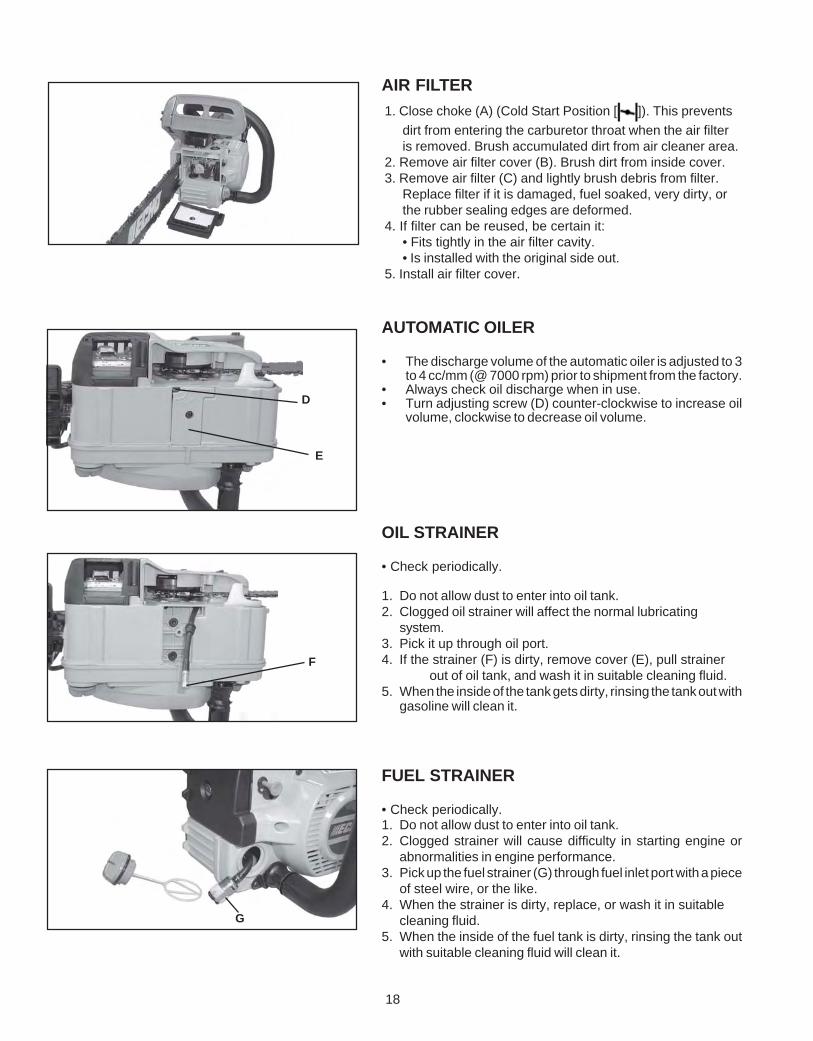
AUTOMATIC OILER
• The discharge volume of the automatic oiler is adjusted to 3to 4 cc/mm (@ 7000 rpm) prior to shipment from the factory.
• Always check oil discharge when in use.• Turn adjusting screw (D) counter-clockwise to increase oil
volume, clockwise to decrease oil volume.
OIL STRAINER
• Check periodically.
1. Do not allow dust to enter into oil tank.2. Clogged oil strainer will affect the normal lubricating
system.3. Pick it up through oil port.4. If the strainer (F) is dirty, remove cover (E), pull strainer
out of oil tank, and wash it in suitable cleaning fluid.5. When the inside of the tank gets dirty, rinsing the tank out with
gasoline will clean it.
FUEL STRAINER
• Check periodically.1. Do not allow dust to enter into oil tank.2. Clogged strainer will cause difficulty in starting engine or
abnormalities in engine performance.3. Pick up the fuel strainer (G) through fuel inlet port with a piece
of steel wire, or the like.4. When the strainer is dirty, replace, or wash it in suitable
cleaning fluid.5. When the inside of the fuel tank is dirty, rinsing the tank out
with suitable cleaning fluid will clean it.
AIR FILTER1. Close choke (A) (Cold Start Position [ ]). This prevents
dirt from entering the carburetor throat when the air filteris removed. Brush accumulated dirt from air cleaner area.
2. Remove air filter cover (B). Brush dirt from inside cover.3. Remove air filter (C) and lightly brush debris from filter.
Replace filter if it is damaged, fuel soaked, very dirty, orthe rubber sealing edges are deformed.
4. If filter can be reused, be certain it:• Fits tightly in the air filter cavity.• Is installed with the original side out.
5. Install air filter cover.
19
Worn : 0.5 mm
J
I
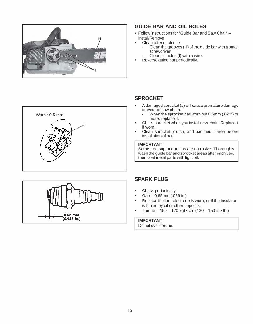
H
GUIDE BAR AND OIL HOLES• Follow instructions for “Guide Bar and Saw Chain –
Install/Remove• Clean after each use
- Clean the grooves (H) of the guide bar with a smallscrewdriver.
- Clean oil holes (I) with a wire.• Reverse guide bar periodically.
SPROCKET• A damaged sprocket (J) will cause premature damage
or wear of saw chain.- When the sprocket has worn out 0.5mm (.020”) or
more, replace it.• Check sprocket when you install new chain. Replace it
if worn.• Clean sprocket, clutch, and bar mount area before
installation of bar.
IMPORTANTSome tree sap and resins are corrosive. Thoroughlywash the guide bar and sprocket areas after each use,then coat metal parts with light oil.
SPARK PLUG
• Check periodically• Gap = 0.65mm (.026 in.)• Replace if either electrode is worn, or if the insulator
is fouled by oil or other deposits.• Torque = 150 – 170 kgf • cm (130 – 150 in • lbf)
IMPORTANTDo not over-torque.

20
COOLING SYSTEM CLEANING
• Remove spark plug lead.
• Remove two (2) muffler cover screws and mufflercover (A).
• Remove four (4) recoil starter housing screws andstarter housing (B).
• Use a stiff bristle cleaning brush (do not us a metalbrush) to remove dirt from cylinder fins in muffler andignition coil areas.
BMUFFLER SPARK ARRESTOR
IMPORTANTCarbon deposits in muffler will cause a drop inengine output and overheating. Spark arrestorscreen must be checked periodically.
1. Remove muffler cover screws and remove mufflercover.
2. Remove spark arrestor screen cover, gaskets, andscreen from muffler body.
3. Clean carbon deposits from muffler components
NOTEWhen cleaning carbon deposit, be careful not todamage the catalytic element inside muffler.
4. Replace screen if it is cracked, plugged, or hasholes burned through.
5. Assemble components in reverse order.
A
CS-306

21
EXHAUST PORT CLEANINGLevel 2.
Tools required: Screwdriver, 4 mm Hex Wrench, Wood or plastic scraper
Parts Required: As needed: Muffler Gasket
1. Remove spark plug lead.
2. Remove muffler cover screws and remove muffler cover.
3. Place piston at top dead center.
4. Remove muffler bolts (A), eyeplate (B), muffler (C), and mufflergasket (D). Check parts for wear or damage, and replace if neces-sary.
5. Use a wood or plastic scraping tool to clean deposits from cylinderexhaust ports (E).
6. Install muffler gasket (D), muffler (C), eyeplate (B), and muffler bolts(A). Tighten bolts to 60-70 kgf • cm (50-60 in • lbf).
7. Connect spark plug lead.
8. Start engine, and allow unit to warm up at idle for several minutes.
9. Stop engine, and re-tighten bolts to to 60-70 kgf • cm 50-60 in • lbf).
10. Install muffler cover and tighten screws.
11. Start engine and check for exhaust leaks between muffler andcylinder head. Stop engine if leak is found and correct problembefore operating chain saw.
A B
C
D
E
22
B
A
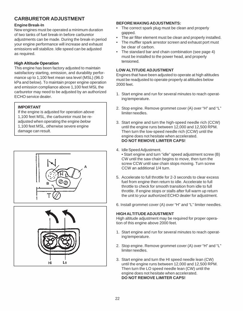
CARBURETOR ADJUSTMENTEngine Break-InNew engines must be operated a minimum durationof two tanks of fuel break-in before carburetoradjustments can be made. During the break-in periodyour engine performance will increase and exhaustemissions will stabilize. Idle speed can be adjustedas required.
High Altitude OperationThis engine has been factory adjusted to maintainsatisfactory starting, emission, and durability perfor-mance up to 1,100 feet mean sea level (MSL) (96.0kPa and below). To maintain proper engine operationand emission compliance above 1,100 feet MSL thecarburetor may need to be adjusted by an authorizedECHO service dealer.
IMPORTANTIf the engine is adjusted for operation above1,100 feet MSL, the carburetor must be re-adjusted when operating the engine below1,100 feet MSL, otherwise severe enginedamage can result.
BEFORE MAKING ADJUSTMENTS:• The correct spark plug must be clean and properly
gapped.• The air filter element must be clean and properly installed.• The muffler spark arrestor screen and exhaust port must
be clear of carbon.• The standard bar and chain combination (see page 4)
must be installed to the power head, and properlytensioned.
LOW ALTITUDE ADJUSTMENTEngines that have been adjusted to operate at high altitudesmust be readjusted to operate properly at altitudes below2000 feet.
1. Start engine and run for several minutes to reach operat-ing temperature.
2. Stop engine. Remove grommet cover (A) over “H” and “L”limiter needles.
3. Start engine and turn the high-speed needle rich (CCW)until the engine runs between 12,000 and 12,500 RPM.Then turn the low-speed needle rich (CCW) until theengine does not hesitate when accelerated.DO NOT REMOVE LIMITER CAPS!
4. Idle Speed Adjustment.• Start engine and turn “idle” speed adjustment screw (B)CW until the saw chain begins to move, then turn thescrew CCW until saw chain stops moving. Turn screwCCW an additional 1/4 turn.
5. Accelerate to full throttle for 2-3 seconds to clear excessfuel from engine then return to idle. Accelerate to fullthrottle to check for smooth transition from idle to fullthrottle. If engine stops or stalls after full warm up returnthe unit to your authorized ECHO dealer for adjustment.
6. Install grommet cover (A) over “H” and “L” limiter needles.
HIGH ALTITUDE ADJUSTMENTHigh altitude adjustment may be required for proper opera-tion of this engine above 2000 feet.
1. Start engine and run for several minutes to reach operat-ing temperature.
2. Stop engine. Remove grommet cover (A) over “H” and “L”limiter needles.
3. Start engine and turn the HI speed needle lean (CW)until the engine runs between 12,000 and 12,500 RPM.Then turn the LO speed needle lean (CW) until theengine does not hesitate when accelerated.DO NOT REMOVE LIMITER CAPS!
23
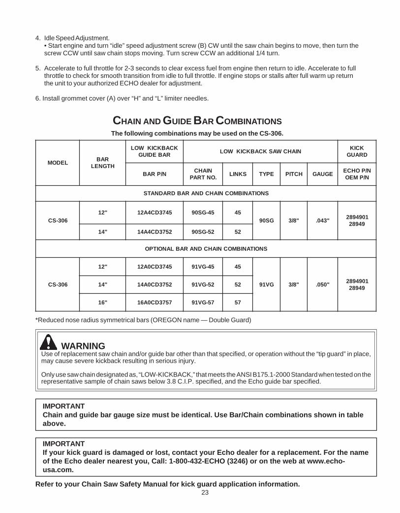
*Reduced nose radius symmetrical bars (OREGON name — Double Guard)
WARNINGUse of replacement saw chain and/or guide bar other than that specified, or operation without the “tip guard” in place,may cause severe kickback resulting in serious injury.
Only use saw chain designated as, “LOW-KICKBACK,” that meets the ANSI B175.1-2000 Standard when tested on therepresentative sample of chain saws below 3.8 C.I.P. specified, and the Echo guide bar specified.
IMPORTANTChain and guide bar gauge size must be identical. Use Bar/Chain combinations shown in tableabove.
IMPORTANTIf your kick guard is damaged or lost, contact your Echo dealer for a replacement. For the nameof the Echo dealer nearest you, Call: 1-800-432-ECHO (3246) or on the web at www.echo-usa.com.
Refer to your Chain Saw Safety Manual for kick guard application information.
CHAIN AND GUIDE BAR COMBINATIONSThe following combinations may be used on the CS-306.
LEDOM RABHTGNEL
KCABKCIKWOLRABEDIUG NIAHCWASKCABKCIKWOL KCIK
DRAUG
N/PRAB NIAHC.ONTRAP SKNIL EPYT HCTIP EGUAG N/POHCE
N/PMEO
SNOITANIBMOCNIAHCDNARABDRADNATS
603-SC"21 5473DC4A21 54-GS09 54
GS09 "8/3 "340. 109498294982
"41 2573DC4A41 25-GS09 25
SNOITANIBMOCNIAHCDNARABLANOITPO
603-SC
"21 5473DC0A21 54-GV19 54
GV19 "8/3 "050. 109498294982"41 2573DC0A41 25-GV19 25
"61 7573DC0A61 75-GV19 75
4. Idle Speed Adjustment.• Start engine and turn “idle” speed adjustment screw (B) CW until the saw chain begins to move, then turn thescrew CCW until saw chain stops moving. Turn screw CCW an additional 1/4 turn.
5. Accelerate to full throttle for 2-3 seconds to clear excess fuel from engine then return to idle. Accelerate to fullthrottle to check for smooth transition from idle to full throttle. If engine stops or stalls after full warm up returnthe unit to your authorized ECHO dealer for adjustment.
6. Install grommet cover (A) over “H” and “L” limiter needles.

24
Type : 90SG
HOLD FILE HOLDERLEVEL
Depthgauge
ONE FIFTH OF FILE DIAMETERREMAINS ABOVE CUTTER EDGE
To sharpen other type chain, follow chain manufacturer’s instructions
30°
PUSH FILE AS SHOWN
Keep this angle
1/5
For setting 90SG saw chains, round file 4.5 mm (11/64”) and flat file are used. For 91VG 4.0mm (5/32”).• To keep correct position and correct angle, use the file holder.
- Round file and flat file are available from your Echo Dealer.
• File cutters as below.
SETTING THE SAW CHAIN
90°
Depth gaugetool
Removeuntil flatwith tool
Roundoff theedge
30°
75° 90SG
80° 91VG
50° 90SG
60° 91VG0.64 mm (0.025 in.)
Parallel
• Properly filed cutters are shown below.
(Top plate angle) (Side plate angle) (Top plate cutting angle) (Depth gauge)
• When setting of the chain is finished, soak it in oil and wash away filings completely before using.• When chain has been filed on the bar, supply sufficient oil to it, rotate the chain slowly to wash away the filings
before using again.• If the chain saw is operated with filings clogged in the groove, the saw chain and the guide bar will be damaged
prematurely• If the saw chain becomes soiled with resin, for instance, clean it with kerosene and soak it in oil.
• Place the depth gauge tool firmly on guide bar so that depth gauge protrudes. Then file top of depth gauge with flatfile until flat with top of the gauge tool.- Be sure to round off the front edge of the depth gauge.
(90)Number
indicates Chaintype
Numberindicates
Chain type
(90S)
(SPROCKET)
(DRIVE LINK)
A B
CHAIN TYPE AND SPROCKET PITCHSaw chain should be used with corresponding pitchedsprocket. To identify chain type and pitch of sprocket,check as follows.
• Chain type number (A) is stamped on drive link.• Sprocket pitch (B) is stamped on clutch drum.

25
TROUBLESHOOTINGPoor performance of the engine and/or cutting mechanism can normally be prevented by carefully following theseinstructions.Poor performance can easily be corrected even by a beginner.When the engine does not function properly check the following three (3) points first.
• Is the engine compression adequate?• Is fuel system in good condition and is enough fuel being supplied?• Is electrical system in good condition and is spark plug operating normally?When there is serious trouble with the unit, do not try to repair it yourself but have your distributor or dealer do it foryou. For detailed TROUBLESHOOTING refer to tables 1 and 2. Locate the problem on the following charts and repair asnecessary.
23
Fuel is not
reaching carburetor
Fuel is not reachingcylinder
Eng
ine
does
not
sta
rt (o
r, is
diff
icul
t to
star
t)
Eng
ine
cran
ks
The
re is
fuel
in th
e ta
nk
Fue
l is
reac
hing
car
bure
tor
Fue
l is
reac
hing
cyl
inde
r
The
re is
spa
rk a
t hig
hte
nsio
n co
rd e
nd
The
re is
spa
rk a
t plu
g
Sta
rting
pro
cedu
res
corr
ect
No spark at hightension cord end.
No spark at plug
Fuel does notkeep running
Accelerationand low speedfunctiondefective
Carburetoroverflow
Engine doesnot crank ○ ○ ○ ○ ○
○ ○ ○
○ ○ ○
○ ○ ○
○ ○
○ ○ ○
○ ○ ○ ○ ○ ○
○ ○ ○ ○ ○
Fuel strainer clogged ................................... Clean.
Fuel pipe clogged ..................................... Clean.
Suction insufficient ................................... Make sufficient.
Strainer clogged ........................................ Clean.
Carburetor out of order ............................. Disassemble and check.
C.D.I. module defective ............................ Remove and replace.
Ignition coil defective ............................... Remove and replace.
Wire connection defective ........................ Reconnect.
High-tension cord connection defective . Repair as necessary.
Switch is grounded .................................... Switch on.
Insulator cracked ........................................ Replace plug.
Spark gap incorrect ................................... Adjust.
Covered with carbon ................................. Clean or replace.
Fouled with fuel ........................................ Clean or replace.
Starting procedures incorrect ................... Start correctly.
Low and high speed needle .................... Readjust.
setting too lean
Table 1
Metering lever spring too strong .............. Readjust.
Fuel pump diaphragm defective ............. Replace.
Fuel passage clogged with dust .............. Disassemble and clean.
Fuel leaking from fixing surfaces ............. Retighten all screws.of carburetor
Air valve, fuel tank cap does notwork normally ............................................... Replace or Clean.
Fuel pump does not operate .................... Check impulse drilling.
Fuel inlet needle valve clogged with dust Clean.
Metering lever spring not placedin dent of lever .............................................. Correct.
Muffler sticky with fuel .............................. Fuel mixture is too rich
Start the engine several timeswith choke rod fully open andrun at fast idle until enginedoes not smoke.
Bearing damaged ..................................... Disassemble and replace.
Piston and/or cylinder seized ................... Disassemble and replace.
Crankshaft worn ......................................... Disassemble and replace.
Crankshaft contacting crankcase .............. Disassemble and replace.

26
WARNINGFuel vapors are extremely flammable and may cause fire and/or explosion. Never test for ignition spark by ground-ing spark plug near cylinder plug hole, otherwise serious personal injury may result.
Improper fuel used ........................................ Use fuel with correct mixing ratio. Never usegasoline of poor quality.
Spark plug defective (worn) ........................... Replace.
Oup
ut (e
ngin
e sp
eed)
insu
ffici
ent
Eng
ine
keep
s ru
nnin
g, b
ut c
hain
doe
s no
t cut
cle
an
Out
put (
engi
ne s
peed
) suf
ficie
nt
Engineoverheated
Firing functiondefective
Carburetordefective
Othertroubles
Chain does not cutclean
Chain stops(Clutch slips)
Chain poorlylubricated
As cooling fins clogged, airdoes not pass well ........................................ Clean fins.
Excessive deposits in
combustion chamber ..................................... Disassemble and remove carbon.
Plug damaged or fouled ................................ Replace or clean.
Comubstion poor due todefective wiring ............................................ Check wiring.
High-speed needle setting incorrect ............. Readjust.
Carburetor overflow ...................................... Refer to Table 1.
Air cleaner clogged ..................................... Clean as necessary.
Compression insufficient(piston ring stuck or worn out) ...................... Disassemble, check and replace if necessary.
Cylinder chromium plating peeled ................. Replace cylinder
or worn out
Exhaust port clogged with carbon ................. Clean as necessary.
Throttle is not fully open ................................ Readjust.
Chain tension incorrect ................................ Adjust.
Chain wrongly set ......................................... Set correctly.
Depth incorrect ............................................ Readjust.
Chain saw pressed againsttree to firmly ................................................. Press lightly.
Clutch shoe worn out .................................... Replace.
No oil in tank ................................................ Refill.
Oil delivery incorrect ..................................... Adjust.
Oil contaminated with dust ............................ Rinse tank and fill with new oil..
Oil viscosity inappropriate ............................. Use oil with correct viscosity for summer or winter.
Table 2

27
STORAGE AFTER USE• Inspect and adjust every part of the chain saw.
- Completely clean every part, and repair, if necessary.
- Apply thin coating of oil on metal parts to prevent rust.
- Remove chain and guide bar.
• Drain fuel tank, pull starter slowly a few times to drain fuel from carburetor.
• Pour a small amount of clean two-stroke oil into spark plug hole, pull starter and crank engine until the piston is at TOP DEADCENTER.
• Store in a dry area, free from dust.
CORRECT USE OF CHAIN BRAKEThe installation of a chain brake may be mandatory by law or as stipulated by insurance regulations in your area ofoperation. You should inquire through local government offices, your employer or your local dealer to ensure that yourchain saw conforms to the required safety standard. Echo chain brakes have been designed and tested to comply withinternational safety standards as follows.
USA: ANSI Standard B175.1-2000 Safety Requirement for chain saws
Canada: CSA Standard Z 62.1 CHAIN SAWS
WARNINGANSI Standard B175.1-2000 stipulates that the brake shall stop the chain in 0.15 seconds maximum (.12 sec avg)at full throttle. It is the responsibility of the Owner/Operator to ensure that the brake is serviced, adjusted and testedstrictly in accordance with the instructions as detailed herein in order to ensure that the brake performance ismaintained in compliance with the Standard B175.1-2000.

28
TESTING THE BRAKE• Start the engine on a solid level surface and run at a fast idle
until warm.
• Hold the saw firmly by the handles and accelerate the engineto a fast idle.
• Slowly operate the chain brake lever while holding the sawfirmly on the ground. When the brake lever trips, the chainshould stop. Immediately release the throttle trigger.
IMPORTANTDo not allow the saw to tip forward in order toavoid damage to the chain.
If the chain does not stop, immediately return the saw to yourauthorized Echo dealer for repair.
Kickback Motion:
• When the bar nose hits another tree, etc.
• Improper thrust cutting.
Function:
• When the lever is pushed forward, chain brake instantlyworks to stop the chain.
Release:
• When the lever is fully pulled toward the operator, brake isreleased.
INSTALLATION• Echo recommends that the chain brake should be serviced
by an authorized Echo servicing dealer.
OPERATION• Set the lever in the released position before starting to cut.
• If the brake is tripped by kick back reaction, the chain willstop. Immediately release the throttle to avoid possibledamage to the engine or clutch.
• Do not attempt to operate the engine with the brake en-gaged.
DANGERNever operate saw if chain brake does notfunction properly, otherwise saw damage andserious personal injury could result. See“Testing the Brake” instructions.

29
NOTES

30
NOTES

31
NOTES

DEALER? Call1-800-432-ECHO
1-800-432-3246or
www.echo-usa.com
CONSUMER PRODUCTSUPPORT
1-800-673-15588:30 - 4:30 Mon - Fri C.S.T.
ECHO, INCORPORATED400 OAKWOOD ROAD
LAKE ZURICH, IL 60047www.echo-usa.com
ADDITIONAL OR REPLACEMENT MANUALSSafety Manuals in English/Spanish or English/French are available, free of charge, from your ECHO dealer or atwww.echo-usa.com.Operator's and Parts Manuals are available by:• Downloading free from www.echo-usa.com• Purchasing from your Echo Dealer.• Manuals are available by sending a written request stating the model number and serial number of your Echo unit,
part number of the manual, your name and address, and mail to the address below.Safety Videos are available from your Echo dealer. A $5.00 shipping charge will be required for each video.
SERVICING INFORMATION
PARTS/SERIAL NUMBERGenuine ECHO Parts and ECHO REPOWER™ Parts and Assembliesfor your ECHO products are available only from an Authorized ECHODealer. When you do need to buy parts always have the ModelNumber and Serial Number of the unit with you. You can find thesenumbers on the engine housing. For future reference, write them inthe space provided below.
Model Number _____________ Serial Number ____________
SERVICEAn Authorized ECHO Service Dealer must perform Service of thisproduct during the warranty period. For the name and address of theAuthorized ECHO Service Dealer nearest you, ask your retailer orcall: 1-800-432-ECHO (3246). Dealer information is also availableon our Web Site. When presenting your unit for Warranty service/repairs, proof of purchase is required.
ECHO CONSUMER PRODUCT SUPPORTIf you require assistance or have questions concerning the application,operation or maintenance of this product you may call the ECHOConsumer Product Support Department at 1-800-673-1558 from 8:30am to 4:30 pm (Central Standard Time) Monday through Friday.Before calling, please know the model and serial number of your unitto help your Consumer Product Support Representative.
WARRANTY REGISTRATIONTo ensure trouble free warranty coverage it is important that youregister your ECHO equipment on-line at www.echo-usa.com. Otherregistration options are by automated phone at 1-800-432-3246 or byfilling out the warranty registration card supplied with your unit.Registering your product confirms your warranty coverage andprovides a direct link between you and ECHO if we find it necessary tocontact you.
C07511001001/C07511999999C08411001001/C08411999999