Embed Size (px)
Citation preview
Translation of the original repair instruction, compiled: 06.08.15
512170020_Inst_en_Version_CSU_00
Pneumatic Sabre Saw
Type 5 1217 0020
Techn. Doc. No. 552
Illustration can differ from the original
Repair Manual and Spare Parts List
P n e u m a t i c Sabre Saw 5 1217 0020
Translation of the original repair instruction, compiled: 06.08.15
512170020_Inst_en_Version_CSU_00 Page 1 of 10
Repair
Disassembly Disassembly and re-assembly should be done according to the sectional drawing only. Observe the safety instructions of the operation and maintenance manual.
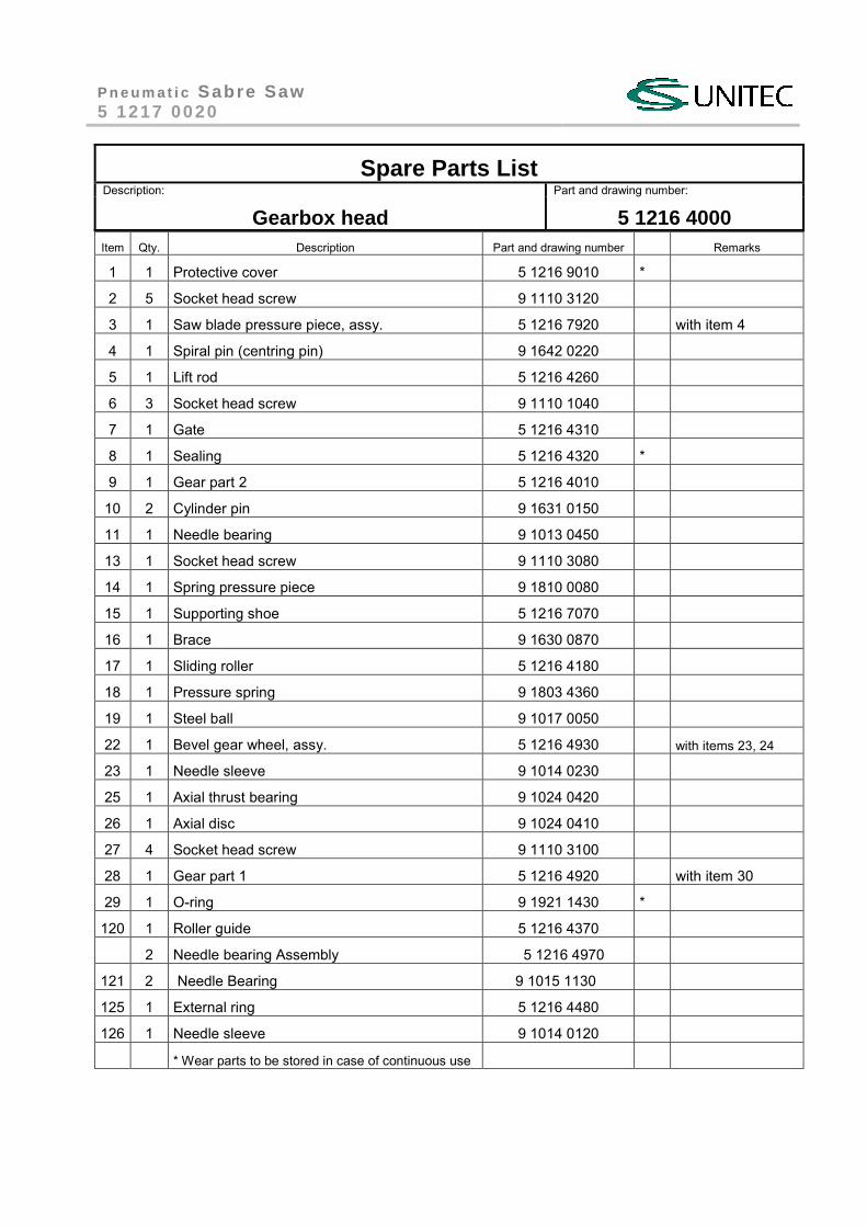
Gearbox head Remove protective cover item1. Loosen socket head screws item 2 and remove gear part 2 item 9. Pull out of gear part 1 item 28 inner parts such as: roller guide item 120 with bearings, roller holder item 124 with bearings, bevel gear item 24, axial thrust bearing item 25 and axial disc item 26. Remove supporting shoe item 15 from gear part 2 item 9. Undo screws item 6 and take out gate item 7 and sealing item 8. Screw out spring pressure piece item 14, pull out lift rod item 5, remove cylinder pin item 10, needle bearing item 11 and sliding roller item 17.
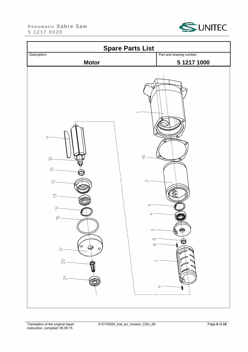
Motor Undo screws item 31 and draw off complete handle. Screw out motor cover item 17 and take out o-ring item 16. Knock out inner motor parts. Press out all inner parts of the motor. By tapping with a rubber mallet on end plate item 3, cylinder bushing item 7 can be removed. Draw off end plate item 3 with bearing item 4 and spacer item 6 from rotor item 10, remove cylinder bushing item 7, as well as vanes item 11. Separate pinion item 20 from rotor and remove end plate item 12 with bearing from rotor. Remove spacer item 15 from the bearing seat. Pull sound absorber item 2 out of motor housing item 1.
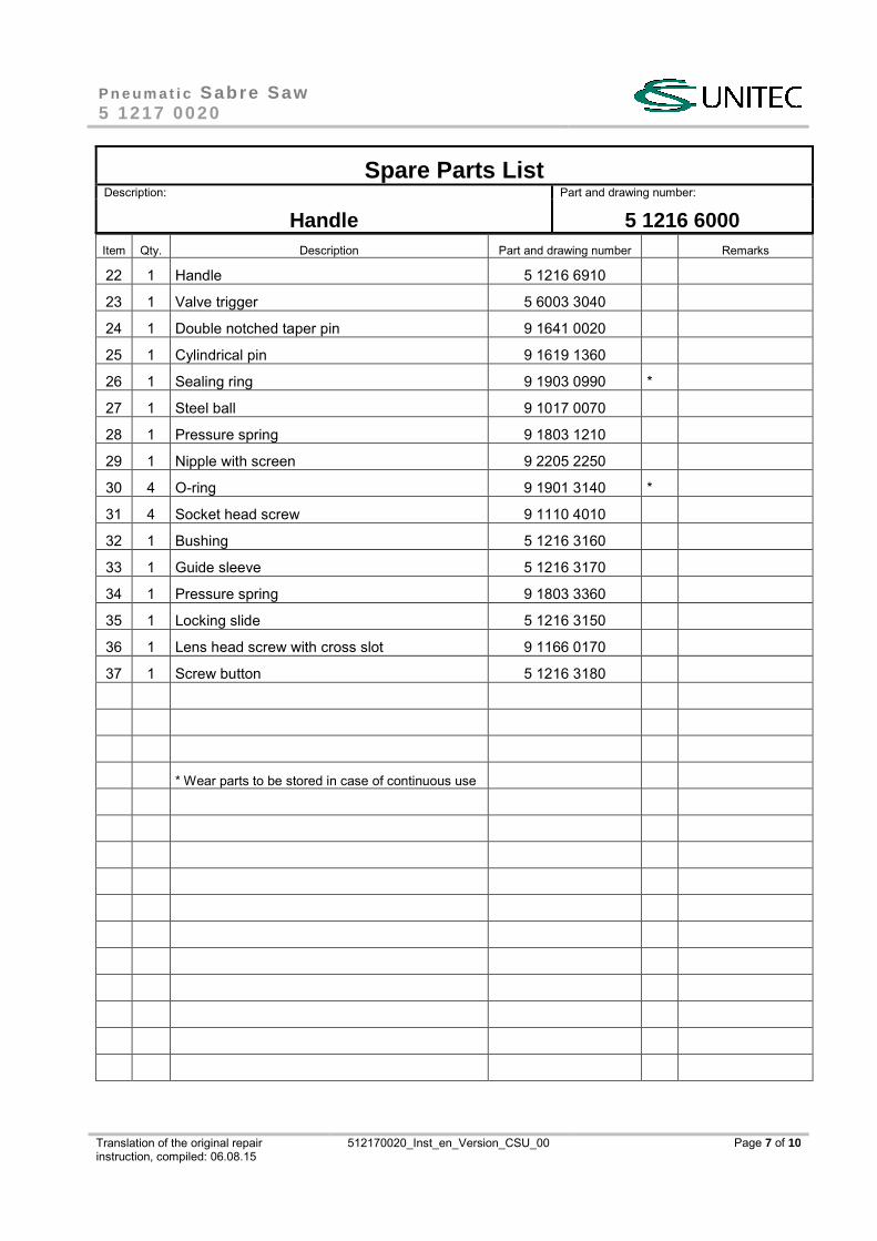
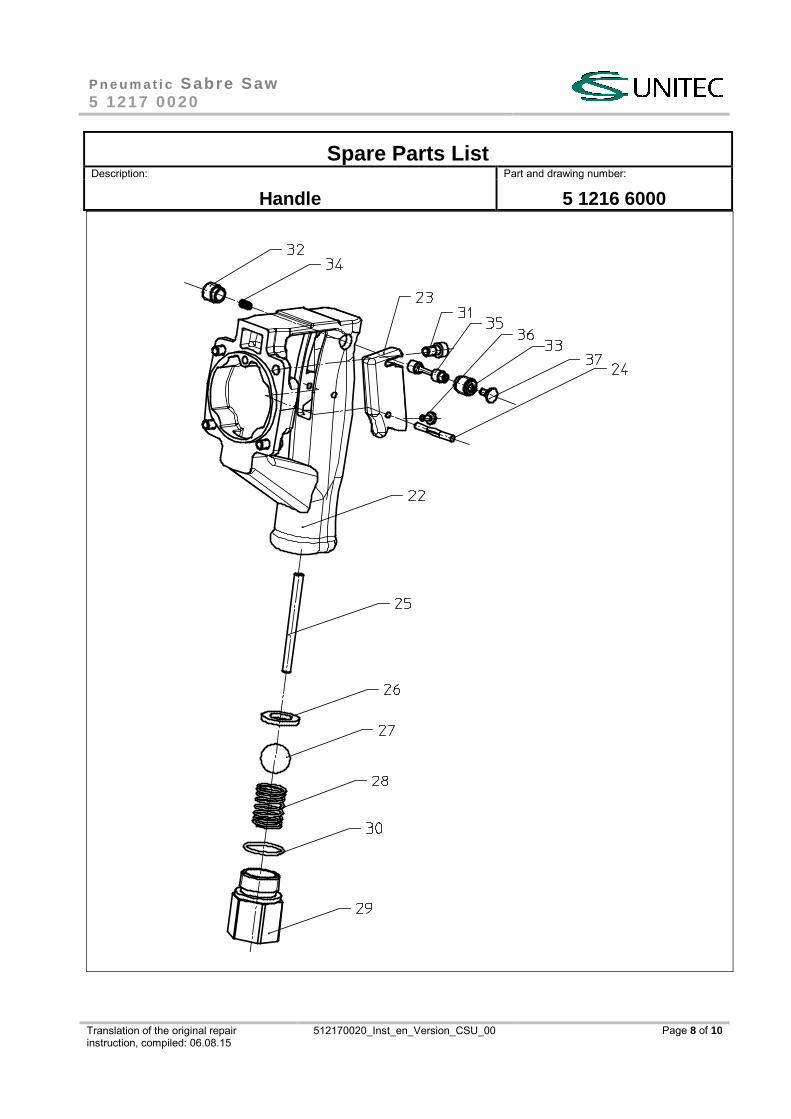
Handle Screw out nipple item 29 with reducing nipple. Take out compression spring item 28, steel ball item 27, pin item 25 and sealing ring item 26. Knock out double notched taper pin item 24 and remove valve trigger item 23. Replace bushing item 32, guide sleeve item 33, pressure spring item 34 and locking slide item 35 only when defective. Bushing item 32 and guide sleeve item 33 are glued in and can be loosened only after heating.
Re-assembly Re-assembly is performed basically the same as disassembly, but in reverse order. Mind especially the following items!
Handle Control function after assembly. Look out for leaks and correct pin guide on the valve trigger. Check the locking bolt.
Motor If bearings items 4 and 13 in the end plates items 3 and 12 were replaced, the spacing of the motor has to be redone. For that, new spacers items 6 and 15 are used. Press bearings in the end plates backlash-free in direction to snap ring in order to find out dimension of spacer. The end play between rotor and end plates should be approx. 0.04 mm per side, to ensure free running of the rotor. Make functional gauging of motor with handle by checking free speed (approx. 15,000 rpm at an operating pressure of 6 bar).
Gearbox head Build-in lift rod item 5 in correct position. Check the complete assembled bevel gear item 24 with bearings and bolts for easy running. Attach roller holder item 124 completely. Test roller guide for easy movement. Screw together gear part 1 and gear part 2 and pull over protective cover. Screw components „Motor with Handle “ and „ Gearbox head“. Fill the gear with grease, e.g. Calypsol-D8024 (approx. 80 g). After completion of re-assembly make following functional gauging: Cutting capacity, Power, start reaction
P n e u m a t i c Sabre Saw 5 1217 0020
Translation of the original repair instruction, compiled: 06.08.15
512170020_Inst_en_Version_CSU_00 Page 2 of 10
Replacement of Vanes For replacing the main wear parts (the vanes) proceed as follows: Disconnect air hose from handle. After loosening screws item 27 of gearbox, take off motor with handle. Remove pinion item 20 from rotor journal. Screw out motor cover item 17. Draw out rotor item 10 with end plate item 12 and vanes item 11. Tapping with a rubber mallet onto edge of the motor housing item 1 is helpful. Doing that, also cylinder bushing item 7 with rear end plate item 3 can be drawn out.
CAUTION! Do not cant/ Never use force!
Change vanes item 11, clean rotor slots, check surfaces and smooth them, if necessary. Push cylinder bushing item 7 into housing. Take care for correct position. Put in spacers item 6 again, looking for that the inner chamfer as well as spacer item 15 point to the rotor. Insert rotor item 10 with the new vanes item11 and spacer item 15. Install end plate item 12 with bearing. Put in O-ring item 16 and fasten motor cover with screws. Now rotor has to be turned easily. If not, light tapping with a rubber mallet straight or lateral on motor housing is helpful to put the rotor in free-wheel position. Thereupon mount the pinion item 20 and screw on gearbox. Connect air hose and perform functional gauging.
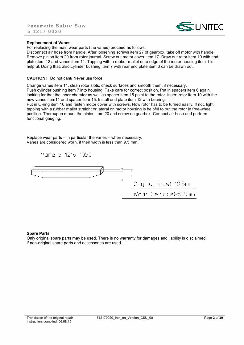
Replace wear parts – in particular the vanes – when necessary. Vanes are considered worn, if their width is less than 9.5 mm.
Spare Parts Only original spare parts may be used. There is no warranty for damages and liability is disclaimed, if non-original spare parts and accessories are used.
P n e u m a t i c Sabre Saw 5 1217 0020
Translation of the original repair instruction, compiled: 06.08.15
512170020_Inst_en_Version_CSU_00 Page 3 of 10
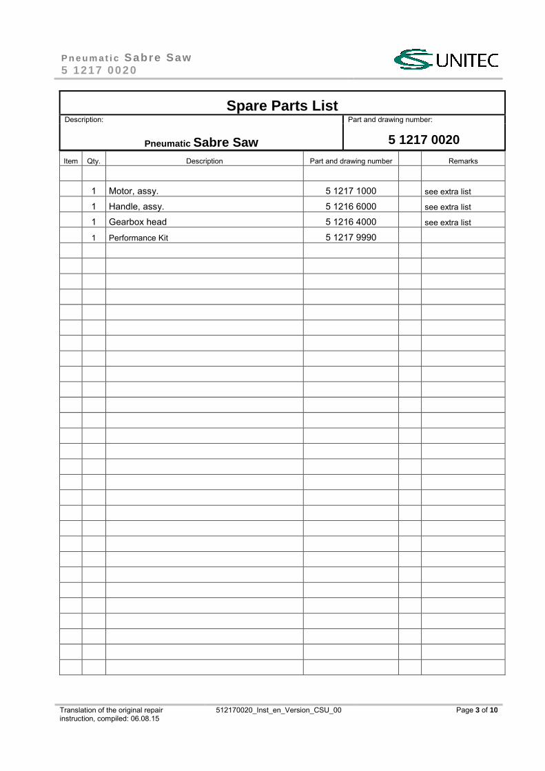
Spare Parts List Description: Part and drawing number:
Pneumatic Sabre Saw
5 1217 0020
Item Qty. Description Part and drawing number Remarks
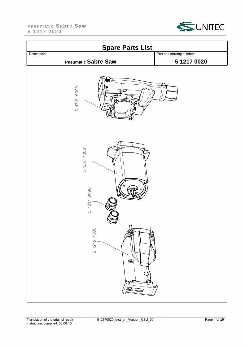
1 Motor, assy. 5 1217 1000 see extra list
1 Handle, assy. 5 1216 6000 see extra list
1 Gearbox head 5 1216 4000 see extra list
1 Performance Kit 5 1217 9990
P n e u m a t i c Sabre Saw 5 1217 0020
Translation of the original repair instruction, compiled: 06.08.15
512170020_Inst_en_Version_CSU_00 Page 4 of 10
Spare Parts List Description: Part and drawing number:
Pneumatic Sabre Saw 5 1217 0020
P n e u m a t i c Sabre Saw 5 1217 0020
Translation of the original repair instruction, compiled: 06.08.15
512170020_Inst_en_Version_CSU_00 Page 5 of 10
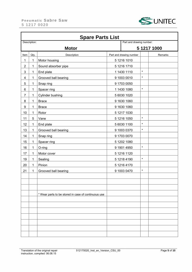
Spare Parts List Description: Part and drawing number:
Motor 5 1217 1000 Item Qty. Description Part and drawing number Remarks
1 1 Motor housing 5 1216 1010
2 1 Sound absorber pipe 5 1216 1710
3 1 End plate 1 1430 1110 *
4 1 Grooved ball bearing 9 1003 0010 *
5 1 Snap ring 9 1703 0050
6 1 Spacer ring 1 1430 1080 *
7 1 Cylinder bushing 5 6030 1020
8 1 Brace 9 1630 1060
9 1 Brace 9 1630 1060
10 1 Rotor 5 1217 1030
11 5 Vane 5 1216 1050 *
12 1 End plate 5 6030 1100 *
13 1 Grooved ball bearing 9 1003 0370 *
14 1 Snap ring 9 1703 0070
15 1 Spacer ring 5 1202 1080
16 1 O-ring 9 1901 4950 *
17 1 Motor cover 5 1216 1120
19 1 Sealing 5 1218 4190 *
20 1 Pinion 5 1216 4170
21 1 Grooved ball bearing 9 1003 0470 *
* Wear parts to be stored in case of continuous use
P n e u m a t i c Sabre Saw 5 1217 0020
Translation of the original repair instruction, compiled: 06.08.15
512170020_Inst_en_Version_CSU_00 Page 6 of 10
Spare Parts List Description: Part and drawing number:
Motor 5 1217 1000
P n e u m a t i c Sabre Saw 5 1217 0020
Translation of the original repair instruction, compiled: 06.08.15
512170020_Inst_en_Version_CSU_00 Page 7 of 10
Spare Parts List Description: Part and drawing number:
Handle 5 1216 6000 Item Qty. Description Part and drawing number Remarks
22 1 Handle 5 1216 6910
23 1 Valve trigger 5 6003 3040
24 1 Double notched taper pin 9 1641 0020
25 1 Cylindrical pin 9 1619 1360
26 1 Sealing ring 9 1903 0990 *
27 1 Steel ball 9 1017 0070
28 1 Pressure spring 9 1803 1210
29 1 Nipple with screen 9 2205 2250
30 4 O-ring 9 1901 3140 *
31 4 Socket head screw 9 1110 4010
32 1 Bushing 5 1216 3160
33 1 Guide sleeve 5 1216 3170
34 1 Pressure spring 9 1803 3360
35 1 Locking slide 5 1216 3150
36 1 Lens head screw with cross slot 9 1166 0170
37 1 Screw button 5 1216 3180
* Wear parts to be stored in case of continuous use
P n e u m a t i c Sabre Saw 5 1217 0020
Translation of the original repair instruction, compiled: 06.08.15
512170020_Inst_en_Version_CSU_00 Page 8 of 10
Spare Parts List Description: Part and drawing number:
Handle 5 1216 6000
P n e u m a t i c Sabre Saw 5 1217 0020
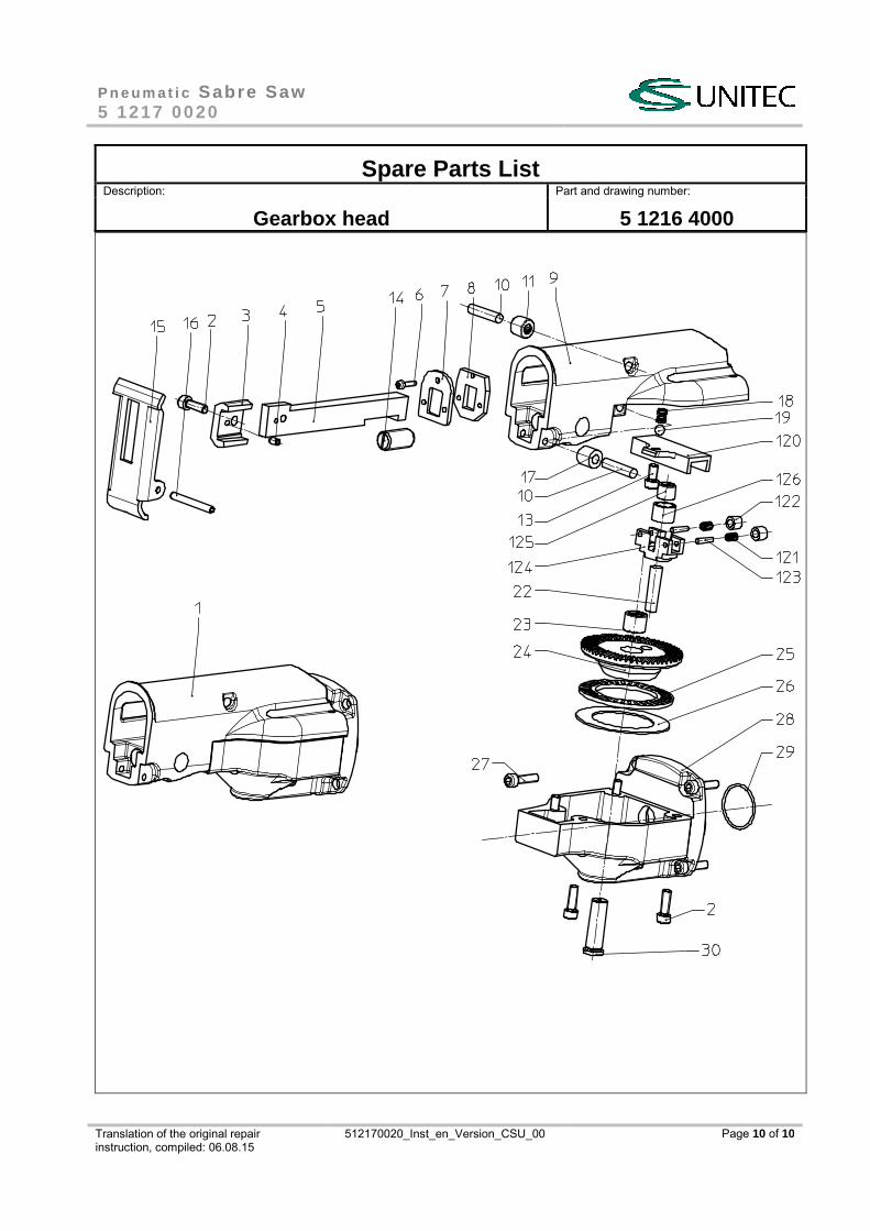
Spare Parts List Description: Part and drawing number:
Gearbox head 5 1216 4000 Item Qty. Description Part and drawing number Remarks
1 1 Protective cover 5 1216 9010 *
2 5 Socket head screw 9 1110 3120
3 1 Saw blade pressure piece, assy. 5 1216 7920 with item 4
4 1 Spiral pin (centring pin) 9 1642 0220
5 1 Lift rod 5 1216 4260
6 3 Socket head screw 9 1110 1040
7 1 Gate 5 1216 4310
8 1 Sealing 5 1216 4320 *
9 1 Gear part 2 5 1216 4010
10 2 Cylinder pin 9 1631 0150
11 1 Needle bearing 9 1013 0450
13 1 Socket head screw 9 1110 3080
14 1 Spring pressure piece 9 1810 0080
15 1 Supporting shoe 5 1216 7070
16 1 Brace 9 1630 0870
17 1 Sliding roller 5 1216 4180
18 1 Pressure spring 9 1803 4360
19 1 Steel ball 9 1017 0050
22 1 Bevel gear wheel, assy. 5 1216 4930 with items 23, 24
23 1 Needle sleeve 9 1014 0230
25 1 Axial thrust bearing 9 1024 0420
26 1 Axial disc 9 1024 0410
27 4 Socket head screw 9 1110 3100
28 1 Gear part 1 5 1216 4920 with item 30
29 1 O-ring 9 1921 1430 *
120 1 Roller guide 5 1216 4370
2 Needle bearing Assembly 5 1216 4970
121 2 Needle Bearing 9 1015 1130
125 1 External ring 5 1216 4480
126 1 Needle sleeve 9 1014 0120
* Wear parts to be stored in case of continuous use
P n e u m a t i c Sabre Saw 5 1217 0020
Translation of the original repair instruction, compiled: 06.08.15
512170020_Inst_en_Version_CSU_00 Page 10 of 10
Spare Parts List Description: Part and drawing number:
Gearbox head 5 1216 4000

Translation of the original repair instruction, compiled: 06.08.15
512170020_Inst_en_Version_CSU_00
CS Unitec, Inc. 22 Harbor Ave, Norwalk, CT 06850 USA
Toll-free: 1-800-700-5919 (USA & Canada) Phone: 203-853-9522 (outside USA & Canada) Fax: 203-853-9921 E-Mail: [email protected] Internet: www.csunitec.com