Embed Size (px)
Citation preview
Instruction Manual
E05121-K00121-002009.10.01Ver. 3-1.01
HKS ELECTRONICS TECHNOLOGY
NOTICEThis manual assumes that you have and know how to use the tools and equip-ment necessary to safely perform service operations on your vehicle. This manual assumes that you are familiar with typical automotive systems and basic service and repair procedures.Do not attempt to carry out the operations shown in this manual unless these assumptions are correct. Always have access to a factory repair manual. To avoid injury, follow the safety precautions contained in the factory repair manual.
-1-
INTRODUCTION
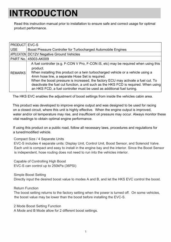
PRODUCTUSEAPPLICATIONPART No.
REMARKS
EVC-SBoost Pressure Controller for Turbocharged Automobile EnginesDC12V Negative Ground Vehicles45003-AK009・A fuel controller (e.g. F-CON V Pro, F-CON iS, etc) may be required when using this product.・When installing this product on a twin turbocharged vehicle or a vehicle using a 4mm hose line, a separate Hose Set is required.・When the boost pressure is increased, the factory ECU may activate a fuel cut. To deactivate the fuel cut function, a unit such as the HKS FCD is required. When using an HKS FCD, a fuel controller must be used as additional fuel tuning.
Read this instruction manual prior to installation to ensure safe and correct usage for optimal product performance.
The HKS EVC enables the adjustment of boost settings from inside the vehicles cabin area.
This product was developed to improve engine output and was designed to be used for racing on a closed circuit, where this unit is highly effective. When the engine output is improved, water and/or oil temperature may rise, and insufficient oil pressure may occur. Always monitor these vital readings to obtain optimal engine performance.
If using this product on a public road, follow all necessary laws, procedures and regulations for a tuned/modified vehicle.
●Compact Size / 4 Separate Units EVC-S includes 4 separate units: Display Unit, Control Unit, Boost Sensor, and Solenoid Valve. Each unit is compact and easy to install in the engine bay and the interior. Since the Boost Sensor is independent, hose routing does not need to run into the vehicles interior.
●Capable of Controlling High Boost EVC-S can control up to 250kPa (36PSI)
●Simple Boost Setting Directly input the desired boost value to modes A and B, and let the HKS EVC control the boost.
●Return Function The boost setting returns to the factory setting when the power is turned off. On some vehicles, the boost value may be lower than the boost before installing the EVC-S.
●2 Mode Boost Setting Function A Mode and B Mode allow for 2 different boost settings.
-2-
●Warning Function If the boost level exceeds the warning value, the unit will warn the user will an audible buzzer and visually on the display. The boost value will be lowered to the set value. This function protects the engine and turbocharger from excessive boost.
●After Image Display Function When the boost changes from positive pressure to negative pressure, the maximum boost under positive pressure can be displayed for 3 seconds. This function can be turned off.
●Data Memory Function Each setting value is saved in the internal memory; the saved values are retrievable even after the ignition is shut-off or the battery is disconnected.
●Exhaust Bypass Select Function Can be used as swing valve type (internal wastegate/actuator) or poppet valve type (external wastegate) for a large capacity turbocharger.
●Boost Unit of Measure Select Function The boost unit of measure is selectable between kPa and PSI.
●Data Lock Function The setting data can be protected by a password to prevent unwanted or accidental changes.
● This manual indicates items you need to pay attention to in order to install this product safely and lists precautions to avoid any possible damage and/or accidents.● For any missing, defective and/or damaged parts, contact your Authorized HKS Dealer.● This product was developed for racing use. To use this product on public roads, follow the necessary laws, procedures and regulations for a tuned/modified vehicle.● HKS will not be responsible for any damage caused by incorrect installation and/or use or use after modification and/or dismantling of this product.● This product was designed based on installing it onto a factory vehicle or a vehicle using other HKS products. The performance and/or safety cannot be guaranteed if this product was installed onto other inapplicable vehicles.● This product works only on vehicles with a DC12V negative ground.● The specifications of this product are subject to be changed without notice.● This manual is subject to be revised without notice. ● This manual must be given to the end user after installation is complete.
-3-
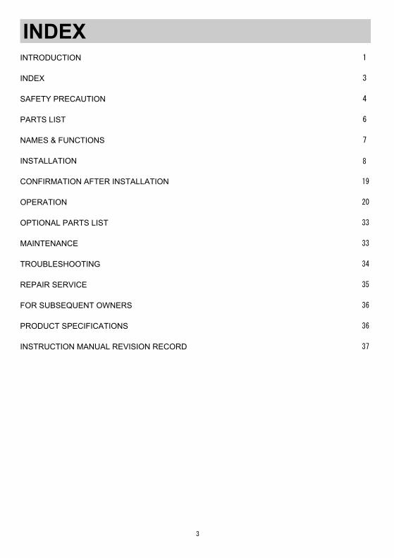
INTRODUCTION …………………………………………………………………………………………
INDEX ……………………………………………………………………………………………………
SAFETY PRECAUTION …………………………………………………………………………………
PARTS LIST ………………………………………………………………………………………………
NAMES & FUNCTIONS …………………………………………………………………………………
INSTALLATION …………………………………………………………………………………………
CONFIRMATION AFTER INSTALLATION …………………………………………………………
OPERATION ………………………………………………………………………………………………
OPTIONAL PARTS LIST ………………………………………………………………………………
MAINTENANCE …………………………………………………………………………………………
TROUBLESHOOTING ……………………………………………………………………………………
REPAIR SERVICE ………………………………………………………………………………………
FOR SUBSEQUENT OWNERS …………………………………………………………………………
PRODUCT SPECIFICATIONS …………………………………………………………………………
INSTRUCTION MANUAL REVISION RECORD ………………………………………………………
INDEX1
3
4
6
7
19
20
33
33
34
35
36
36
37
8
-4-
SAFETY PRECAUTION
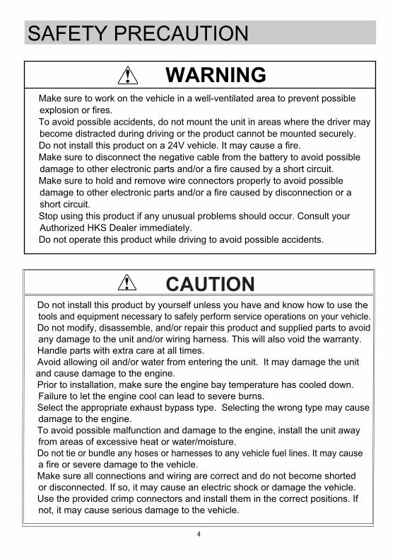
WARNING●Make sure to work on the vehicle in a well-ventilated area to prevent possible explosion or fires.●To avoid possible accidents, do not mount the unit in areas where the driver may become distracted during driving or the product cannot be mounted securely.●Do not install this product on a 24V vehicle. It may cause a fire.●Make sure to disconnect the negative cable from the battery to avoid possible damage to other electronic parts and/or a fire caused by a short circuit.●Make sure to hold and remove wire connectors properly to avoid possible damage to other electronic parts and/or a fire caused by disconnection or a short circuit.●Stop using this product if any unusual problems should occur. Consult your Authorized HKS Dealer immediately.●Do not operate this product while driving to avoid possible accidents.
●Do not install this product by yourself unless you have and know how to use the tools and equipment necessary to safely perform service operations on your vehicle.●Do not modify, disassemble, and/or repair this product and supplied parts to avoid any damage to the unit and/or wiring harness. This will also void the warranty.●Handle parts with extra care at all times.●Avoid allowing oil and/or water from entering the unit. It may damage the unit and cause damage to the engine. ●Prior to installation, make sure the engine bay temperature has cooled down. Failure to let the engine cool can lead to severe burns.●Select the appropriate exhaust bypass type. Selecting the wrong type may cause damage to the engine.●To avoid possible malfunction and damage to the engine, install the unit away from areas of excessive heat or water/moisture. ●Do not tie or bundle any hoses or harnesses to any vehicle fuel lines. It may cause a fire or severe damage to the vehicle.●Make sure all connections and wiring are correct and do not become shorted or disconnected. If so, it may cause an electric shock or damage the vehicle. ●Use the provided crimp connectors and install them in the correct positions. If not, it may cause serious damage to the vehicle.
CAUTION
-5-
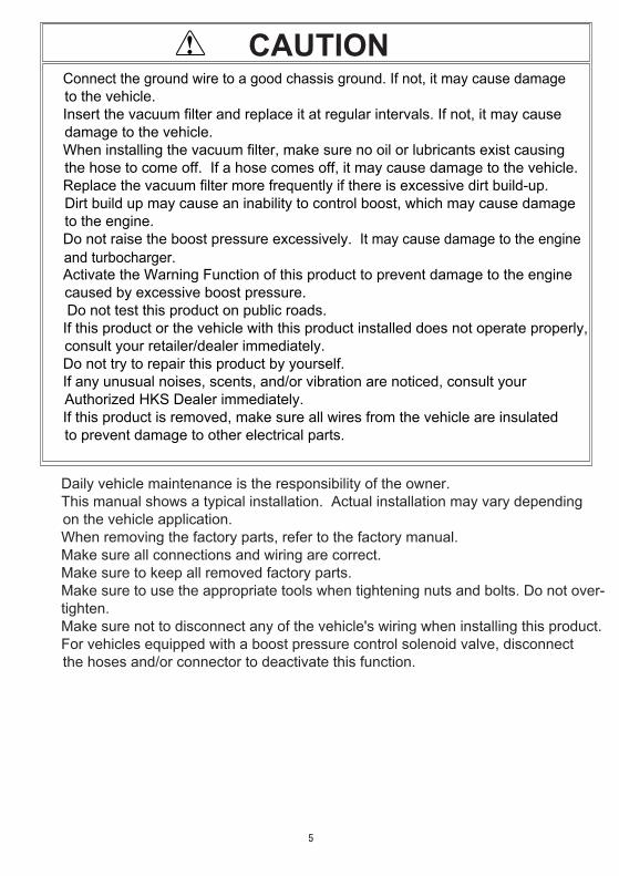
●Connect the ground wire to a good chassis ground. If not, it may cause damage to the vehicle. ●Insert the vacuum filter and replace it at regular intervals. If not, it may cause damage to the vehicle.●When installing the vacuum filter, make sure no oil or lubricants exist causing the hose to come off. If a hose comes off, it may cause damage to the vehicle.●Replace the vacuum filter more frequently if there is excessive dirt build-up. Dirt build up may cause an inability to control boost, which may cause damage to the engine.●Do not raise the boost pressure excessively. It may cause damage to the engine and turbocharger.●Activate the Warning Function of this product to prevent damage to the engine caused by excessive boost pressure.● Do not test this product on public roads.●If this product or the vehicle with this product installed does not operate properly, consult your retailer/dealer immediately.●Do not try to repair this product by yourself.●If any unusual noises, scents, and/or vibration are noticed, consult your Authorized HKS Dealer immediately.●If this product is removed, make sure all wires from the vehicle are insulated to prevent damage to other electrical parts.
CAUTION
・Daily vehicle maintenance is the responsibility of the owner.・This manual shows a typical installation. Actual installation may vary depending on the vehicle application.・When removing the factory parts, refer to the factory manual.・Make sure all connections and wiring are correct.・Make sure to keep all removed factory parts.・Make sure to use the appropriate tools when tightening nuts and bolts. Do not over- tighten.・Make sure not to disconnect any of the vehicle's wiring when installing this product.・For vehicles equipped with a boost pressure control solenoid valve, disconnect the hoses and/or connector to deactivate this function.
-6-
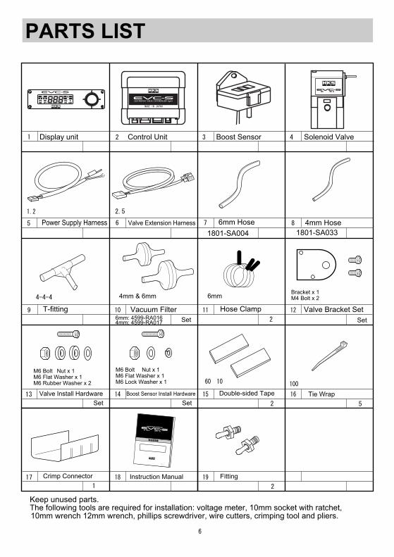
PARTS LIST
Instruction Manual
Valve Bracket Set
Bracket x 1M4 Bolt x 2
Double-sided Tape
Crimp Connector
Tie Wrap
Hose Clamp Vacuum FilterT-fitting
4mm Hose
Control Unit Solenoid ValveDisplay unit1 1 1
1
1Set
1
1Set
5
2 3 4
8
10 11 12
14
18
15 16
1.2m
6mm
100mm
1m
φ4-4-4 4mm & 6mm
●Keep unused parts.●The following tools are required for installation: voltage meter, 10mm socket with ratchet, 10mm wrench 12mm wrench, phillips screwdriver, wire cutters, crimping tool and pliers.
Power Supply Harness
1
6mm Hose1801-SA0331801-SA004
6mm: 4599-RA0164mm: 4599-RA017
Boost Sensor
Valve Extension Harness1
2.5m
6 7
取付けは、必ず専門業者に依頼してください。取付け前及びご使用前に必ずお読みになってください。本書はお読みになった後も、本製品の側に置いてご活用ください。
ご使用中にわからないことや、不具合が生じた際に便利です。
△△△-△△20○○年○月○日発行Ver.3-1.0□
1
19
1
OFS
A B
SET P.H.
WRN
LOCK
RSP
DRO PSI
kPa %
MADE IN JAPAN
NO
1 1
1
5
9
13
17
2
M6 Bolt ・Nut x 1M6 Flat Washer x 1M6 Rubber Washer x 2
Valve Install Hardware1Set
Boost Sensor Install Hardware
1Set
M6 Bolt ・Nut x 1M6 Flat Washer x 1 M6 Lock Washer x 1
2
60×10mm
HKS ELECTRONICS TECHNOLOGY
OPT
Fitting2
-7-
OFS
A B
SET P.H.
WRN
LOCK
RSP
DRO PSI
kPa %
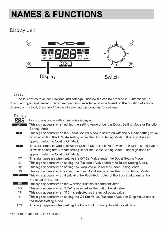
NAMES & FUNCTIONS
●Switch Use this switch to select functions and settings. This switch can be pressed in 5 directions: up, down, left, right, and center. Each direction has 2 selectable options based on the duration of switchdepression. In total, there are 10 ways of selecting functions and/or settings.
●Display Boost pressure or setting value is displayed. This sign appears when editing the setting value under the Boost Setting Mode or Function Setting Mode. This sign appears when the Boost Control Mode is activated with the A Mode setting value, or when editing the A Mode setting under the Boost Setting Mode. This sign does not appear under the Control Off Mode. This sign appears when the Boost Control Mode is activated with the B Mode setting value, or when editing the B Mode setting under the Boost Setting Mode. This sign does not appear under the Control Off Mode. This sign appears when setting the Off Set Value under the Boost Setting Mode. This sign appears when setting the Response Value under the Boost Setting Mode. This sign appears when setting the Drop Value under the Boost Setting Mode. This sign appears when setting the Over Boost Value under the Boost Setting Mode. This sign appears when displaying the Peak Hold Value of the Boost value under the Boost Control Mode. This sign appears when the Warning function is being activated. This sign appears when "kPa" is selected as the unit of boost value. This sign appears when "PSI" is selected as the unit of boost value. This sign appears when setting the Off Set Value, Response Value or Drop Value under the Boost Setting Mode. This sign appears when setting the Data Lock, or trying to edit locked data.
For more details, refer to "Operation."
Display Switch
Display Unit
OPT
OFS
A
B
SET
P.H.
WRN
LOCK
RSP
DRO
PSI
kPa
%
OPT
-8-
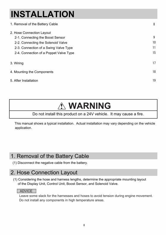
INSTALLATION
(1) Disconnect the negative cable from the battery.
●This manual shows a typical installation. Actual installation may vary depending on the vehicle application.
1. Removal of the Battery Cable
2. Hose Connection Layout
●Do not install this product on a 24V vehicle. It may cause a fire.WARNING
1. Removal of the Battery Cable ………………………………………………………………………
2. Hose Connection Layout
3. Wiring …………………………………………………………………………………………………
4. Mounting the Components ……………………………………………………………………………
5. After Installation ………………………………………………………………………………………
8
9
10
11
15
2-1. Connecting the Boost Sensor …………………………………………………………………
2-2. Connecting the Solenoid Valve …………………………………………………………………
2-3. Connection of a Swing Valve Type ……………………………………………………………
2-4. Connection of a Poppet Valve Type ……………………………………………………………
(1) Considering the hose and harness lengths, determine the appropriate mounting layout of the Display Unit, Control Unit, Boost Sensor, and Solenoid Valve.
ADVICE※Leave some slack for the harnesses and hoses to avoid tension during engine movement.※Do not install any components in high temperature areas.
17
18
19
-9-
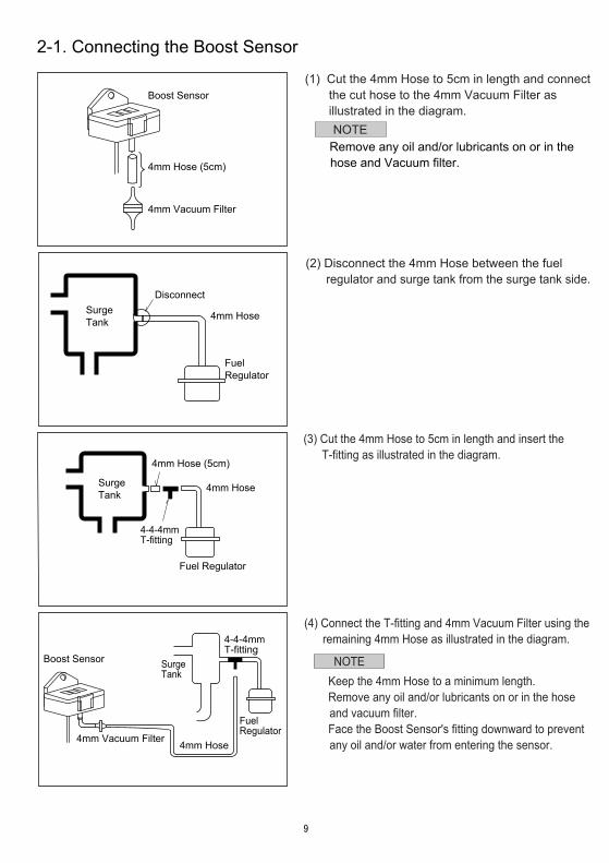
2-1. Connecting the Boost Sensor
・Remove any oil and/or lubricants on or in the hose and Vacuum filter. 4mm Hose (5cm)
4mm Vacuum Filter
SurgeTank
SurgeTank
Disconnect
Fuel Regulator
4mm Hose (5cm)
4mm Hose
Fuel Regulator
4mm Hose
4-4-4mmT-fitting
SurgeTank
4mm Vacuum Filter
Boost Sensor
Fuel Regulator
4mm Hose
4-4-4mmT-fitting
Boost Sensor(1) Cut the 4mm Hose to 5cm in length and connect the cut hose to the 4mm Vacuum Filter as illustrated in the diagram.
NOTE
(2) Disconnect the 4mm Hose between the fuel regulator and surge tank from the surge tank side.
(3) Cut the 4mm Hose to 5cm in length and insert the T-fitting as illustrated in the diagram.
(4) Connect the T-fitting and 4mm Vacuum Filter using the remaining 4mm Hose as illustrated in the diagram.
NOTE・Keep the 4mm Hose to a minimum length.・Remove any oil and/or lubricants on or in the hose and vacuum filter.・Face the Boost Sensor's fitting downward to prevent any oil and/or water from entering the sensor.
-10-
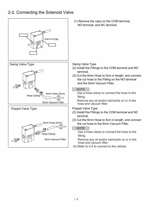
2-2. Connecting the Solenoid Valve
Swing Valve Type(2) Install the Fittings to the COM terminal and NO terminal.(3) Cut the 6mm Hose to 5cm in length, and connect the cut hose to the Fitting on the NO terminal and the 6mm Vacuum Filter.
Swing Valve Type
(1) Remove the caps on the COM terminal, NO terminal, and NC terminal.
Poppet Valve Type(2) Install the Fittings to the COM terminal and NC terminal.(3) Cut the 6mm Hose to 5cm in length, and connect the cut hose to the 6mm Vacuum Filter.
Poppet Valve Type
6mm Hose (5cm)
6mm Vacuum Filter
6mm Hose (5cm)
6mm Vacuum Filter
COM
NO
NC
Hose Clamp
Hose Clamp
Cap
NOTE・Use a hose clamp to connect the hose to the fitting.・Remove any oil and/or lubricants on or in the hose and vacuum filter.
NOTE・Use a hose clamp to connect the hose to the fitting.・Remove any oil and/or lubricants on or in the hose and vacuum filter.
(4) Refer to 2-4 to connect to the vehicle.
-11-
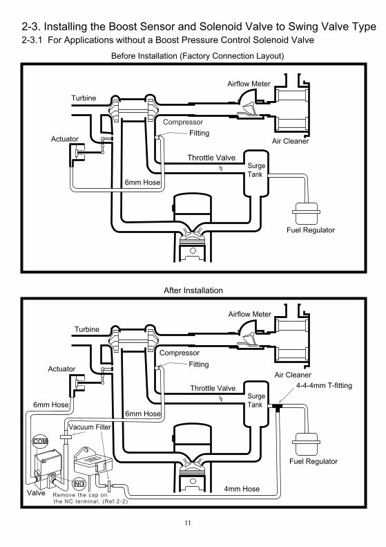
2-3. Installing the Boost Sensor and Solenoid Valve to Swing Valve Type
Before Installation (Factory Connection Layout)
After Installation
Turbine
Actuator
Airflow Meter
Air CleanerFitting ①
6mm Hose
Throttle Valve Surge Tank
Fuel Regulator
2-3.1 For Applications without a Boost Pressure Control Solenoid Valve
Turbine
Actuator
Compressor
Airflow Meter
Air CleanerFitting ①
6mm Hose
Throttle Valve Surge Tank
Fuel Regulator
4mm Hose
4-4-4mm T-fitting
6mm Hose
Vacuum Filter
ValveNO
COM
※Remove the cap on the NC terminal . (Ref.2-2)
Compressor
-12-
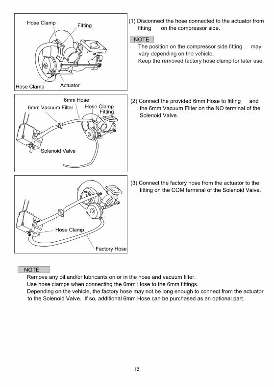
Hose Clamp
Hose Clamp
Hose Clamp
Hose Clamp
Fitting ①
Fitting ①
Actuator
Solenoid Valve
6mm Vacuum Filter6mm Hose
Factory Hose
NOTE・Remove any oil and/or lubricants on or in the hose and vacuum filter.・Use hose clamps when connecting the 6mm Hose to the 6mm fittings.・Depending on the vehicle, the factory hose may not be long enough to connect from the actuator to the Solenoid Valve. If so, additional 6mm Hose can be purchased as an optional part.
(3) Connect the factory hose from the actuator to the fitting on the COM terminal of the Solenoid Valve.
(2) Connect the provided 6mm Hose to fitting ① and the 6mm Vacuum Filter on the NO terminal of the Solenoid Valve.
(1) Disconnect the hose connected to the actuator from fitting ① on the compressor side.
NOTE・The position on the compressor side fitting ① may vary depending on the vehicle.・Keep the removed factory hose clamp for later use.
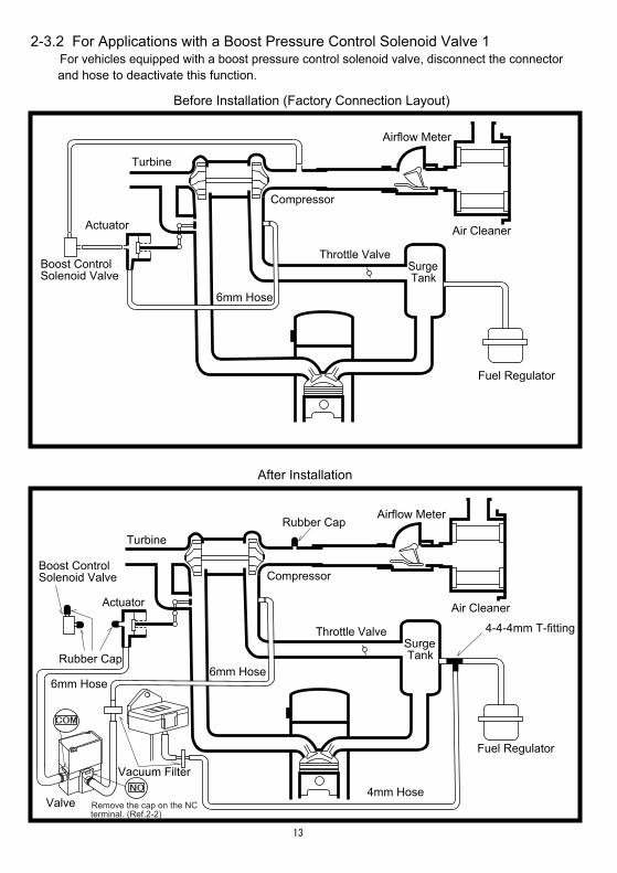
2-3.2 For Applications with a Boost Pressure Control Solenoid Valve 1
Before Installation (Factory Connection Layout)
After Installation
6mm Hose
Turbine
Actuator
Boost ControlSolenoid Valve
Compressor
Airflow Meter
Throttle Valve
Air Cleaner
Surge Tank
Fuel Regulator
6mm Hose
4mm Hose
4-4-4mm T-fitting
6mm Hose
Turbine
Actuator
Boost Control Solenoid Valve Compressor
Airflow Meter
Throttle Valve
Air Cleaner
Surge Tank
Fuel Regulator
Rubber Cap
Rubber Cap
●For vehicles equipped with a boost pressure control solenoid valve, disconnect the connector and hose to deactivate this function.
Vacuum Filter
COM
Valve
-13-
※Remove the cap on the NC terminal. (Ref.2-2)
NO
-14-
Before Installation (Factory Connection Layout)
After Installation
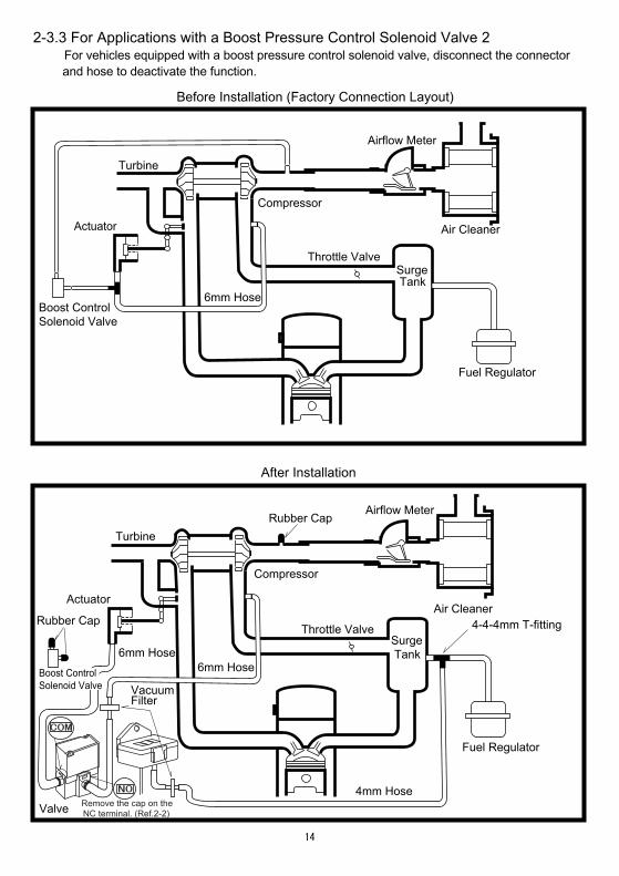
2-3.3 For Applications with a Boost Pressure Control Solenoid Valve 2
6mm Hose
Turbine
Actuator
Boost ControlSolenoid Valve
Compressor
Airflow Meter
Throttle Valve
Air Cleaner
Surge Tank
Fuel Regulator
6mm Hose
4mm Hose
4-4-4mm T-fitting
6mm Hose
Turbine
Actuator
Compressor
Airflow Meter
Throttle Valve
Air Cleaner
Surge Tank
Fuel Regulator
Rubber Cap
Rubber Cap
Valve
● For vehicles equipped with a boost pressure control solenoid valve, disconnect the connector and hose to deactivate the function.
VacuumFilter
COM
NO
※Remove the cap on the NC terminal. (Ref.2-2)
Boost ControlSolenoid Valve
-15-
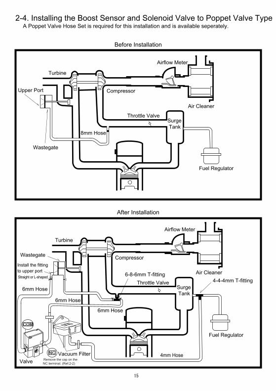
2-4. Installing the Boost Sensor and Solenoid Valve to Poppet Valve Type
Before Installation
After Installation
8mm Hose
Turbine
Compressor
Airflow Meter
Throttle Valve
Air Cleaner
Surge Tank
Fuel Regulator
6mm Hose
6mm Hose
4mm Hose
4-4-4mm T-fitting6mm Hose
Turbine
Compressor
Airflow Meter
Throttle Valve
Air Cleaner
Surge Tank
Fuel Regulator
6-8-6mm T-fitting
Upper Port
Wastegate
Wastegate
Install the fittingto upper port(Straight or L-shaped)
A Poppet Valve Hose Set is required for this installation and is available seperately.
Vacuum FilterValve
COM
NC
※Remove the cap on the NC terminal. (Ref.2-2)
-16-
※Remove any oil and/or lubricants on or in the hose and vacuum filter.
NOTE ※The position of the fitting① on the compressor may vary depending on the vehicle.
Fitting ①
Fitting ①
Cut
5cm
Wastegate
6-8-6mm T-fitting
※Use hose clamps when connecting hoses to fittings.
※Use the 6-8-6mm T-fitting and 8mm Hose Clamp included in the Poppet Valve Hose Set.
6mm Vacuum Filter
6mm Hose
HoseClamp
NC
6mm Hose
Hose Clamp
6mm Fitting
8mm Fitting
8mm Hose
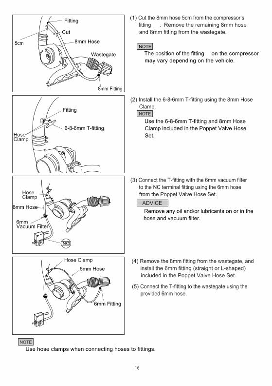
(1) Cut the 8mm hose 5cm from the compressor’s fitting ①. Remove the remaining 8mm hose and 8mm fitting from the wastegate.
(2) Install the 6-8-6mm T-fitting using the 8mm Hose Clamp.
NOTE
(3) Connect the T-fitting with the 6mm vacuum filter to the NC terminal fitting using the 6mm hose from the Poppet Valve Hose Set.
ADVICE
(4) Remove the 8mm fitting from the wastegate, and install the 6mm fitting (straight or L-shaped) included in the Poppet Valve Hose Set.
(5) Connect the T-fitting to the wastegate using the provided 6mm hose.
NOTE
HoseClamp
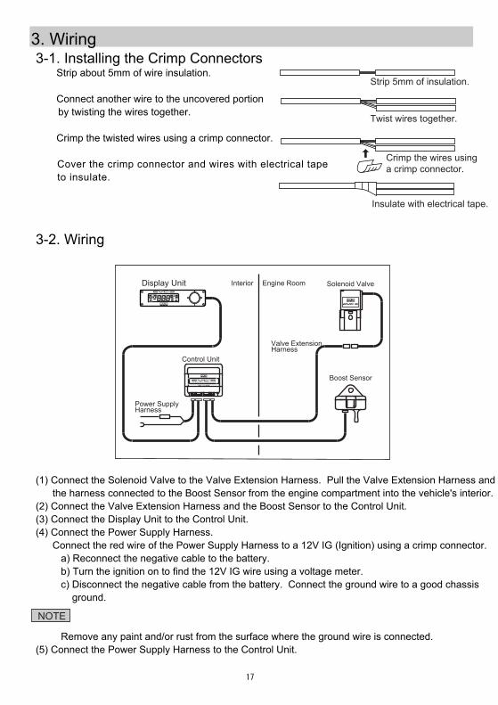
(1) Connect the Solenoid Valve to the Valve Extension Harness. Pull the Valve Extension Harness and the harness connected to the Boost Sensor from the engine compartment into the vehicle's interior.(2) Connect the Valve Extension Harness and the Boost Sensor to the Control Unit.(3) Connect the Display Unit to the Control Unit.(4) Connect the Power Supply Harness. Connect the red wire of the Power Supply Harness to a 12V IG (Ignition) using a crimp connector. a) Reconnect the negative cable to the battery. b) Turn the ignition on to find the 12V IG wire using a voltage meter. c) Disconnect the negative cable from the battery. Connect the ground wire to a good chassis ground.
Remove any paint and/or rust from the surface where the ground wire is connected.(5) Connect the Power Supply Harness to the Control Unit.
3. Wiring 3-1. Installing the Crimp Connectors
① Strip about 5mm of wire insulation.
② Connect another wire to the uncovered portion by twisting the wires together.
③ Crimp the twisted wires using a crimp connector.
④ Cover the crimp connector and wires with electrical tape to insulate.
Strip 5mm of insulation.
Twist wires together.
Crimp the wires usinga crimp connector.
Insulate with electrical tape.
3-2. Wiring
OFS
A B
SET P.H.
WRN
LOCK
RSP
DRO PSI
kPa %
MADE IN JAPAN
NO
Interior Engine Room Solenoid Valve
Boost Sensor
Display Unit
Control Unit
-17-
NOTE
Power SupplyHarness
Valve ExtensionHarness
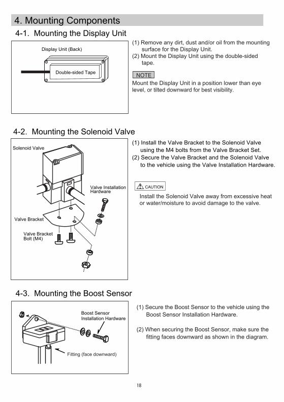
4. Mounting Components
Display Unit (Back)
4-1. Mounting the Display Unit
4-2. Mounting the Solenoid Valve(1) Install the Valve Bracket to the Solenoid Valve using the M4 bolts from the Valve Bracket Set.(2) Secure the Valve Bracket and the Solenoid Valve to the vehicle using the Valve Installation Hardware.
Double-sided Tape
Valve Bracket
Valve BracketBolt (M4)
Solenoid Valve
Valve InstallationHardware
4-3. Mounting the Boost Sensor
Boost SensorInstallation Hardware
Fitting (face downward)
-18-
CAUTION
(1) Remove any dirt, dust and/or oil from the mounting surface for the Display Unit.(2) Mount the Display Unit using the double-sided tape.
Mount the Display Unit in a position lower than eye level, or tilted downward for best visibility.
NOTE
Install the Solenoid Valve away from excessive heator water/moisture to avoid damage to the valve.
(1) Secure the Boost Sensor to the vehicle using the Boost Sensor Installation Hardware.
(2) When securing the Boost Sensor, make sure the fitting faces downward as shown in the diagram.
-19-
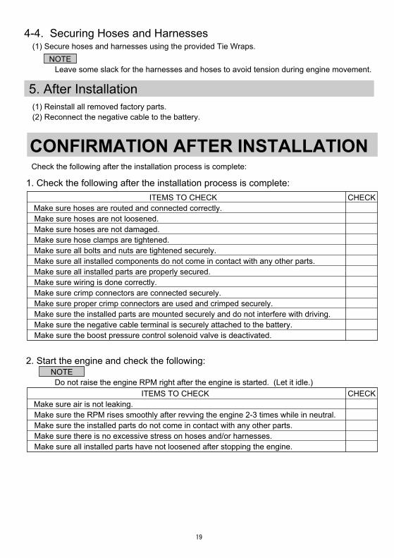
4-4. Securing Hoses and Harnesses
5. After Installation(1) Reinstall all removed factory parts.(2) Reconnect the negative cable to the battery.
(1) Secure hoses and harnesses using the provided Tie Wraps. NOTE ※Leave some slack for the harnesses and hoses to avoid tension during engine movement.
CONFIRMATION AFTER INSTALLATION
NOTE※Do not raise the engine RPM right after the engine is started. (Let it idle.)
CHECK
CHECK ITEMS TO CHECK Make sure hoses are routed and connected correctly. Make sure hoses are not loosened. Make sure hoses are not damaged. Make sure hose clamps are tightened. Make sure all bolts and nuts are tightened securely. Make sure all installed components do not come in contact with any other parts. Make sure all installed parts are properly secured. Make sure wiring is done correctly. Make sure crimp connectors are connected securely. Make sure proper crimp connectors are used and crimped securely. Make sure the installed parts are mounted securely and do not interfere with driving. Make sure the negative cable terminal is securely attached to the battery. Make sure the boost pressure control solenoid valve is deactivated.
Check the following after the installation process is complete:
1. Check the following after the installation process is complete:
2. Start the engine and check the following:
ITEMS TO CHECK Make sure air is not leaking. Make sure the RPM rises smoothly after revving the engine 2-3 times while in neutral. Make sure the installed parts do not come in contact with any other parts. Make sure there is no excessive stress on hoses and/or harnesses. Make sure all installed parts have not loosened after stopping the engine.
OPERATION1. Modes & Display Descriptions ………………………………………………………………
2. Operation Outline ………………………………………………………………………………
3. Boost Control Mode …………………………………………………………………………… 3-1. Boost Control 3-2. Boost Display 3-2.1 Display on the Monitor 3-2.2 Peak Hold Display 3-2.3 After Image Display 3-3. Warning Function
4. Control Off Mode ………………………………………………………………………………
5. Boost Setting Mode …………………………………………………………………………… 5-1. Off Set Setting 5-2. Response Setting 5-3. Over Boost Setting 5-4. Warning Boost Setting 5-5. Drop Boost Setting
6. Function Setting Mode ………………………………………………………………………… 6-1. Unit Setting 6-2. After Image Setting 6-3. Data Lock 6-4. All Data Reset
7. Error Display ……………………………………………………………………………………
-20-
21
23
25
26
27
29
32
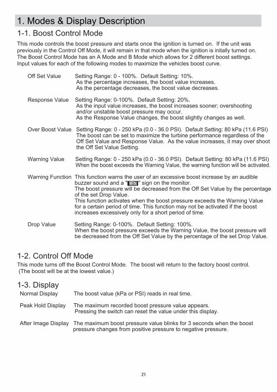
1. Modes & Display Description1-1. Boost Control ModeThis mode controls the boost pressure and starts once the ignition is turned on. If the unit was previously in the Control Off Mode, it will remain in that mode when the ignition is initally turned on. The Boost Control Mode has an A Mode and B Mode which allows for 2 different boost settings. Input values for each of the following modes to maximize the vehicles boost curve.
●Off Set Value Setting Range: 0 - 100%. Default Setting: 10%. As the percentage increases, the boost value increases. As the percentage decreases, the boost value decreases.
●Response Value Setting Range: 0-100%. Default Setting: 20%. As the input value increases, the boost increases sooner; overshooting and/or unstable boost pressure may occur. As the Response Value changes, the boost slightly changes as well.
●Over Boost Value Setting Range: 0 - 250 kPa (0.0 - 36.0 PSI). Default Setting: 80 kPa (11.6 PSI) The boost can be set to maximize the turbine performance regardless of the Off Set Value and Response Value. As the value increases, it may over shoot the Off Set Value Setting.
●Warning Value Setting Range: 0 - 250 kPa (0.0 - 36.0 PSI). Default Setting: 80 kPa (11.6 PSI) When the boost exceeds the Warning Value, the warning function will be activated. ※Warning Function This function warns the user of an excessive boost increase by an audible buzzer sound and a " " sign on the monitor. The boost pressure will be decreased from the Off Set Value by the percentage of the set Drop Value. This function activates when the boost pressure exceeds the Warning Value for a certain period of time. This function may not be activated if the boost increases excessively only for a short period of time.
●Drop Value Setting Range: 0-100%. Default Setting: 100%. When the boost pressure exceeds the Warning Value, the boost pressure will be decreased from the Off Set Value by the percentage of the set Drop Value.
1-2. Control Off ModeThis mode turns off the Boost Control Mode. The boost will return to the factory boost control. (The boost will be at the lowest value.)
1-3. Display・Normal Display The boost value (kPa or PSI) reads in real time.
・Peak Hold Display The maximum recorded boost pressure value appears. Pressing the switch can reset the value under this display. ・After Image Display The maximum boost pressure value blinks for 3 seconds when the boost pressure changes from positive pressure to negative pressure.
-21-
WRN
-22-
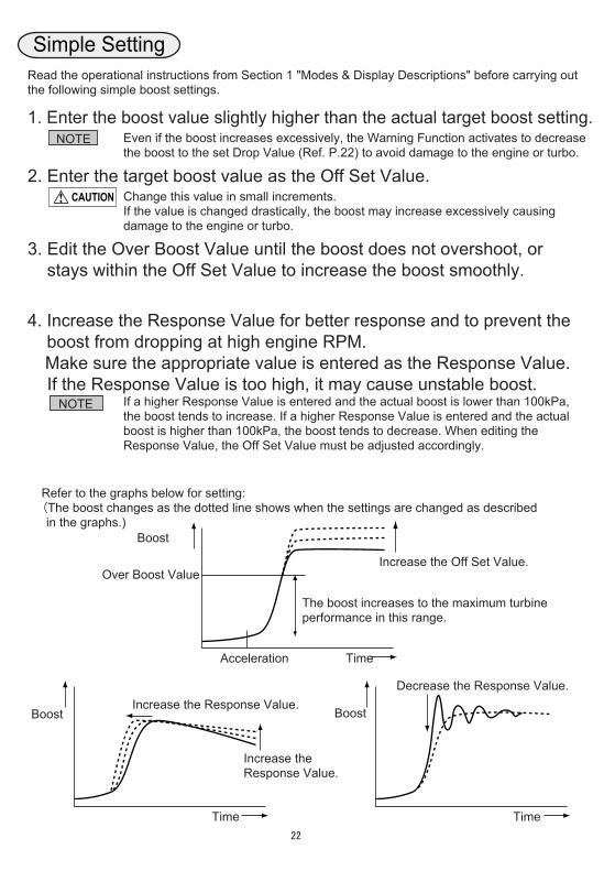
Simple SettingRead the operational instructions from Section 1 "Modes & Display Descriptions" before carrying out the following simple boost settings.
1. Enter the boost value slightly higher than the actual target boost setting.Even if the boost increases excessively, the Warning Function activates to decrease the boost to the set Drop Value (Ref. P.22) to avoid damage to the engine or turbo.
Change this value in small increments.If the value is changed drastically, the boost may increase excessively causing damage to the engine or turbo.
If a higher Response Value is entered and the actual boost is lower than 100kPa, the boost tends to increase. If a higher Response Value is entered and the actual boost is higher than 100kPa, the boost tends to decrease. When editing theResponse Value, the Off Set Value must be adjusted accordingly.
2. Enter the target boost value as the Off Set Value.
3. Edit the Over Boost Value until the boost does not overshoot, or stays within the Off Set Value to increase the boost smoothly.
4. Increase the Response Value for better response and to prevent the boost from dropping at high engine RPM. Make sure the appropriate value is entered as the Response Value. If the Response Value is too high, it may cause unstable boost.
NOTE
CAUTION
Increase the Off Set Value.
Boost
Time
Over Boost Value
Acceleration
Increase the Response Value.
Boost
Time
Increase the Response Value.Boost
Time
Decrease the Response Value.
※Refer to the graphs below for setting: (The boost changes as the dotted line shows when the settings are changed as described in the graphs.)
The boost increases to the maximum turbine performance in this range.
NOTE
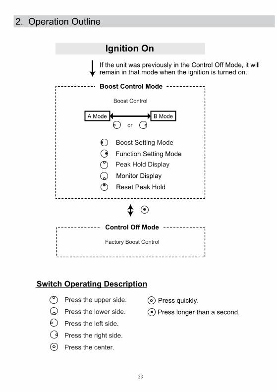
Boost Control Mode
A Mode B Mode
2. Operation Outline
Ignition On
Function Setting Mode
Reset Peak Hold
Boost Setting Mode
Control Off Mode
Factory Boost Control
Boost Control
or
If the unit was previously in the Control Off Mode, it will remain in that mode when the ignition is turned on.
Monitor Display
Peak Hold Display
-23-
Press longer than a second.
Press quickly.Press the upper side.
Press the lower side.
Press the left side.
Press the right side.
Press the center.
Switch Operating Description
-24-
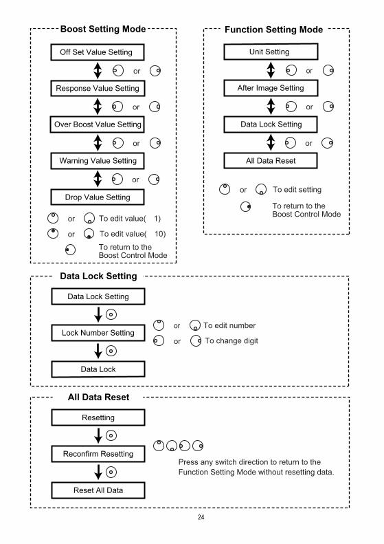
Off Set Value Setting
Response Value Setting
Warning Value Setting
Drop Value Setting
Boost Setting Mode
or
or
or
To edit value(±1) or
To edit value(±10) or
Unit Setting
After Image Setting
Data Lock Setting
All Data Reset
Function Setting Mode
or
or
or
To edit setting or
Press any switch direction to return to the Function Setting Mode without resetting data.
All Data Reset
Resetting
Reconfirm Resetting
Reset All Data
To edit number or
or To change digit
Data Lock Setting
Data Lock Setting
Lock Number Setting
Data Lock
Over Boost Value Setting
or
To return to the Boost Control Mode
To return to the Boost Control Mode
-25-
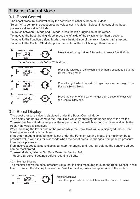
3. Boost Control Mode3-1. Boost Control
The boost pressure value is displayed under the Boost Control Mode.The display can be switched to the Peak Hold value by pressing the upper side of the switch. To reset the Peak Hold value, press the upper side of the switch longer than a second while the Peak Hold value is displayed.When pressing the lower side of the switch while the Peak Hold value is displayed, the current boost pressure value is displayed.If the After Image display function is set under the Function Setting Mode, the maximum boost pressure value will blink for 3 seconds when the boost pressure changes from positive pressure to negative pressure.If an incorrect boost value is displayed, stop the engine and reset all data so the sensor’s valuescan be recalibrated.To reset all data, refer to "All Data Reset" in Section 6-4.※Record all current settings before resetting all data
3-2. Boost Display
A
kPa
A
kPa
A
kPa
A
kPa
A
kPa
Press the left or right side of the switch to select A or B Mode.
Press the left side of the switch longer than a second to go to the Boost Setting Mode.
Press the right side of the switch longer than a second to go to the Function Setting Mode.
Press the center of the switch longer than a second to activate the Control Off Mode.
3-2.1 Monitor Display The monitor shows the boost pressure value that is being measured through the Boost Sensor in real time. To switch the display to show the Peak Hold value, press the upper side of the switch.
Monitor Display: Press the upper side of the switch to see the Peak Hold value.
Selected mode "A" or "B" is shown.
B
The boost pressure is controlled by the set value of either A Mode or B Mode.Select "A" to control the boost pressure values set in A Mode. Select "B" to control the boost pressure values set in B Mode.To switch between A Mode and B Mode, press the left or right side of the switch.To move to the Boost Setting Mode, press the left side of the switch longer than a second.To move to the Function Setting Mode, press the right side of the switch longer than a second.To move to the Control Off Mode, press the center of the switch longer than a second.
-26-
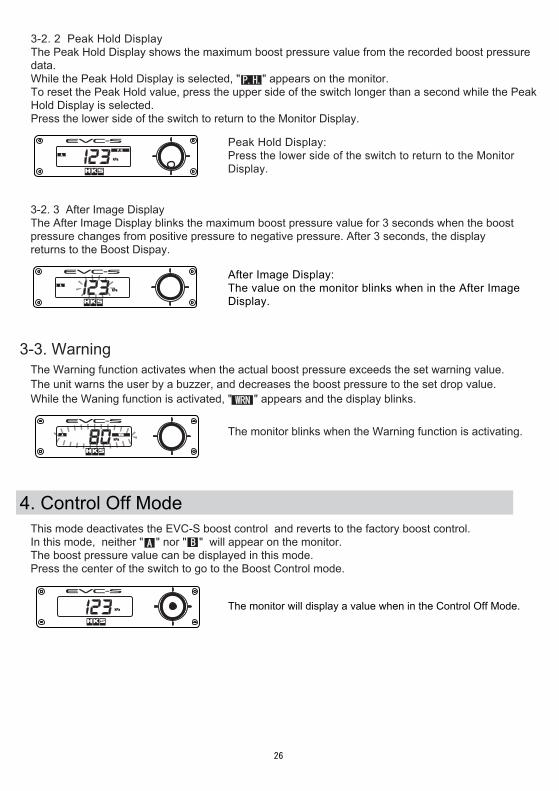
4. Control Off ModeThis mode deactivates the EVC-S boost control and reverts to the factory boost control.In this mode, neither " " nor " " will appear on the monitor.The boost pressure value can be displayed in this mode.Press the center of the switch to go to the Boost Control mode.
kPa
3-3. Warning
A WRN
kPa
3-2. 3 After Image Display
The monitor will display a value when in the Control Off Mode.
After Image Display: The value on the monitor blinks when in the After Image Display.
A
kPa
A
P.H.
kPa
3-2. 2 Peak Hold DisplayThe Peak Hold Display shows the maximum boost pressure value from the recorded boost pressure data.While the Peak Hold Display is selected, " " appears on the monitor.To reset the Peak Hold value, press the upper side of the switch longer than a second while the PeakHold Display is selected.Press the lower side of the switch to return to the Monitor Display.
P.H.
A B
Peak Hold Display: Press the lower side of the switch to return to the Monitor Display.
The After Image Display blinks the maximum boost pressure value for 3 seconds when the boost pressure changes from positive pressure to negative pressure. After 3 seconds, the displayreturns to the Boost Dispay.
The Warning function activates when the actual boost pressure exceeds the set warning value.The unit warns the user by a buzzer, and decreases the boost pressure to the set drop value. While the Waning function is activated, " " appears and the display blinks.
The monitor blinks when the Warning function is activating.
WRN
-27-
5. Boost Setting Mode
5-1. Off Set Value Setting
Off Set Value Setting Display
OFS
A
SET
%
OFS
A
SET
%
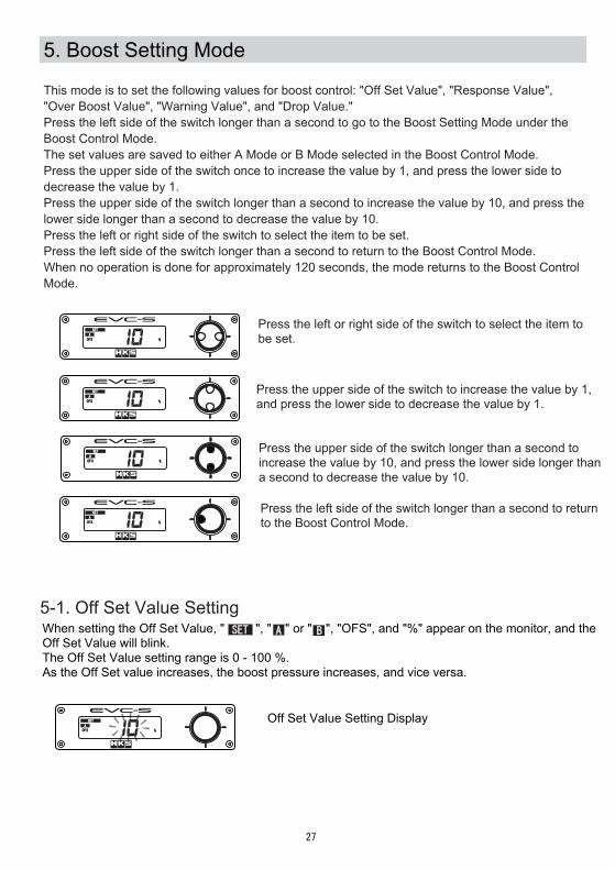
Press the left or right side of the switch to select the item tobe set.
Press the left side of the switch longer than a second to returnto the Boost Control Mode.
OFS
A
SET
%
When setting the Off Set Value, " ", " " or " ", "OFS", and "%" appear on the monitor, and theOff Set Value will blink.The Off Set Value setting range is 0 - 100 %.As the Off Set value increases, the boost pressure increases, and vice versa.
OFS
A
SET
%
OFS
A
SET
%
Press the upper side of the switch to increase the value by 1, and press the lower side to decrease the value by 1.
Press the upper side of the switch longer than a second to increase the value by 10, and press the lower side longer than a second to decrease the value by 10.
SET A B
This mode is to set the following values for boost control: "Off Set Value", "Response Value", "Over Boost Value", "Warning Value", and "Drop Value."Press the left side of the switch longer than a second to go to the Boost Setting Mode under the Boost Control Mode.The set values are saved to either A Mode or B Mode selected in the Boost Control Mode.Press the upper side of the switch once to increase the value by 1, and press the lower side to decrease the value by 1.Press the upper side of the switch longer than a second to increase the value by 10, and press the lower side longer than a second to decrease the value by 10.Press the left or right side of the switch to select the item to be set.Press the left side of the switch longer than a second to return to the Boost Control Mode.When no operation is done for approximately 120 seconds, the mode returns to the Boost Control Mode.

-28-
5-4. Warning Value Setting
5-5. Drop Value Setting
5-2. Response Value SettingWhen setting the Response Value, " ", " " or " ", "RSP", and "%" appear on the monitor, and the Response Value will blink.The Response Value setting range is 0 - 100 %.As the Response Value increases, the boost pressure increases sooner, overshooting and/or unstable boost pressure may occur.
A
SET
RSP % Response Value Setting Display
When setting the Warning Value, " ", " " or " ", " ", and "kPa" or "PSI" appears on the monitor, and the Warning Value will blink. The Warning Value setting range is 0 - 250kPa or 0.0 - 36.0PSI.When the boost pressure exceeds the set Warning Value, a buzzer sounds and the boost value decreases to the Drop Value setting to protect the engine and turbocharger from excessive boost.
A
SET
WRN
kPa
Drop Value Setting DisplayA
SET
DRO
%
5-3. Over Boost Value SettingWhen setting the Over Boost Value, " ", " " or " ", "OPT", " ", and "kPa" or "PSI" appear on the monitor, and the Over Boost Value will blink.The Over Boost Value setting range is 0 - 250kPa or 0.0 - 36.0PSI.The boost can be set to maximize the turbine performance regardless of the Off Set Value and Response Value. As the value increases, it may over shoot the Off Set Value Setting.
Over Boost Value Setting Display A
SET
kPaOPT
P.H.
SET A B
SET A B P.H.
SET A B WRN
Warning Value Setting Display
When setting the Drop Value, " ", " " or " ", "DRO", and "%" appear on the monitor, and the Drop Value will blink.The Drop Value setting range is 0 - 100 %.The Drop Value is the value the boost pressure drops to under the Warning Function.
SET A B
-29-
Under the normal display, an After Image Display showing the highest positive boost pressure can be selected to display. To select the After Image Display, refer to the following procedure.
6-2. After Image Display
To display the After Image Display, select "ON." "AI" and "ON" will alternately blink on the monitor.
SET
SET
SET
SET
To not display the After Image Display, select "OFF." "AI" and "OFF" will alternately blink on the monitor.
To switch between "ON" and "OFF", press the upper or lower side of the switch. Make sure the selected setting appears on the monitor.
6. Function Setting Mode
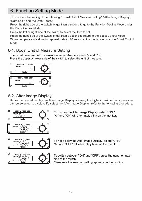
6-1. Boost Unit of Measure SettingThe boost pressure unit of measure is selectable between kPa and PSI.Press the upper or lower side of the switch to select the unit of measure.
SET
PSI
SET
kPa
This mode is for setting of the following: "Boost Unit of Measure Setting", "After Image Display", "Data Lock" and "All Data Reset."Press the right side of the switch longer than a second to go to the Function Setting Mode underthe Boost Control Mode.Press the left or right side of the switch to select the item to set.Press the right side of the switch longer than a second to return to the Boost Control Mode.When no operation is done for approximately 120 seconds, the mode returns to the Boost Control Mode.
-30-
6-3. Data Lock
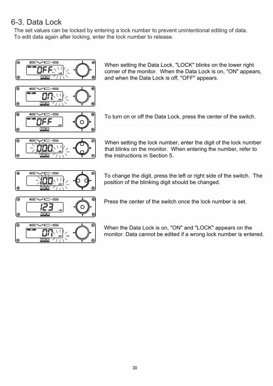
When setting the Data Lock, "LOCK" blinks on the lower right corner of the monitor. When the Data Lock is on, "ON" appears, and when the Data Lock is off, "OFF" appears.
To turn on or off the Data Lock, press the center of the switch.
The set values can be locked by entering a lock number to prevent unintentional editing of data.To edit data again after locking, enter the lock number to release.
To change the digit, press the left or right side of the switch. The position of the blinking digit should be changed.
SET
LOCK
SET
LOCK
SET
LOCK
LOCK
LOCK
LOCK
When setting the lock number, enter the digit of the lock number that blinks on the monitor. When entering the number, refer to the instructions in Section 5.
Press the center of the switch once the lock number is set.
SET
LOCK
When the Data Lock is on, "ON" and "LOCK" appears on the monitor. Data cannot be edited if a wrong lock number is entered.
-31-
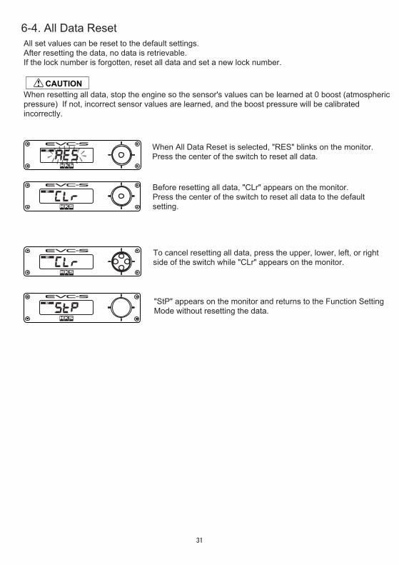
6-4. All Data Reset
When All Data Reset is selected, "RES" blinks on the monitor.Press the center of the switch to reset all data.
Before resetting all data, "CLr" appears on the monitor.Press the center of the switch to reset all data to the default setting.
When resetting all data, stop the engine so the sensor's values can be learned at 0 boost (atmosphericpressure) If not, incorrect sensor values are learned, and the boost pressure will be calibrated incorrectly.
SET
SET
SET
SET
To cancel resetting all data, press the upper, lower, left, or rightside of the switch while "CLr" appears on the monitor.
CAUTION
"StP" appears on the monitor and returns to the Function Setting Mode without resetting the data.
All set values can be reset to the default settings.After resetting the data, no data is retrievable. If the lock number is forgotten, reset all data and set a new lock number.
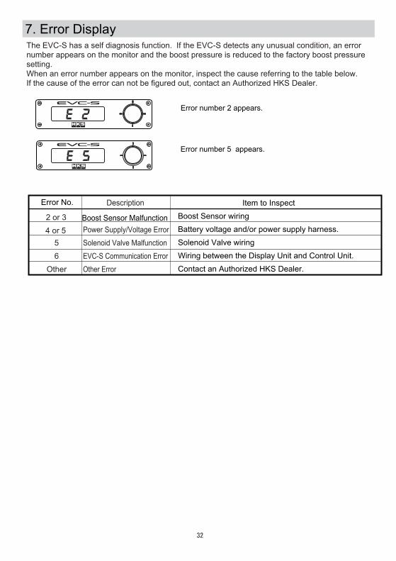
7. Error DisplayThe EVC-S has a self diagnosis function. If the EVC-S detects any unusual condition, an error number appears on the monitor and the boost pressure is reduced to the factory boost pressure setting.When an error number appears on the monitor, inspect the cause referring to the table below. If the cause of the error can not be figured out, contact an Authorized HKS Dealer.
← Error number 2 appears.
← Error number 5 appears.
Error No.
Boost Sensor Malfunction
Item to InspectBoost Sensor wiringBattery voltage and/or power supply harness.Solenoid Valve wiringWiring between the Display Unit and Control Unit.Contact an Authorized HKS Dealer.
2 or 34 or 5
56
Other
Description
Power Supply/Voltage ErrorSolenoid Valve MalfunctionEVC-S Communication ErrorOther Error
-32-
-33-
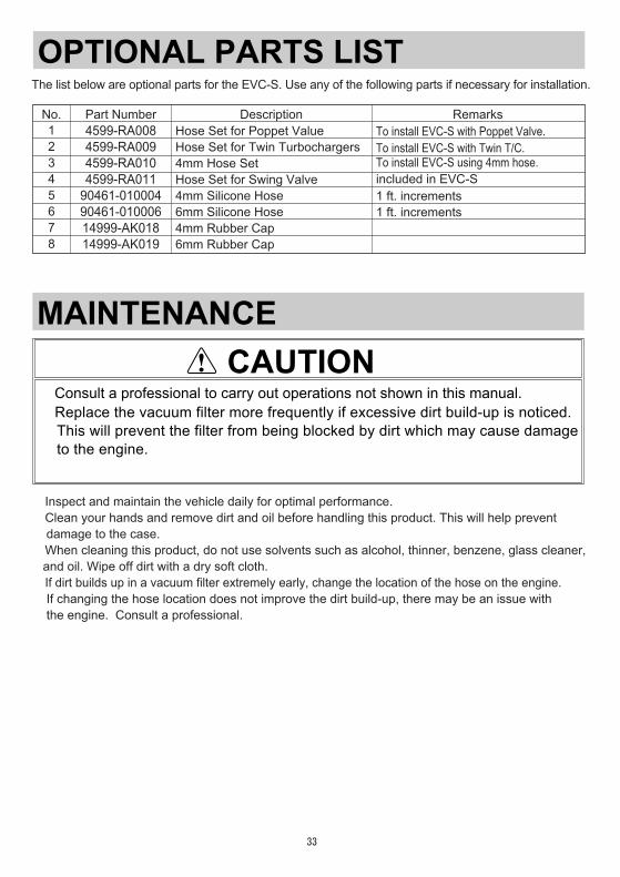
MAINTENANCECAUTION
●Consult a professional to carry out operations not shown in this manual.●Replace the vacuum filter more frequently if excessive dirt build-up is noticed. This will prevent the filter from being blocked by dirt which may cause damage to the engine.
・Inspect and maintain the vehicle daily for optimal performance.�・Clean your hands and remove dirt and oil before handling this product. This will help prevent damage to the case.�・When cleaning this product, do not use solvents such as alcohol, thinner, benzene, glass cleaner, and oil. Wipe off dirt with a dry soft cloth.・If dirt builds up in a vacuum filter extremely early, change the location of the hose on the engine. If changing the hose location does not improve the dirt build-up, there may be an issue with the engine. Consult a professional.
OPTIONAL PARTS LISTThe list below are optional parts for the EVC-S. Use any of the following parts if necessary for installation.
No. Part Number Description Remarks12345678
4599-RA0084599-RA0094599-RA0104599-RA011
90461-01000490461-01000614999-AK01814999-AK019
Hose Set for Poppet ValueHose Set for Twin Turbochargers4mm Hose SetHose Set for Swing Valve4mm Silicone Hose6mm Silicone Hose4mm Rubber Cap6mm Rubber Cap
To install EVC-S with Poppet Valve.To install EVC-S with Twin T/C.To install EVC-S using 4mm hose.included in EVC-S1 ft. increments�1 ft. increments
-34-
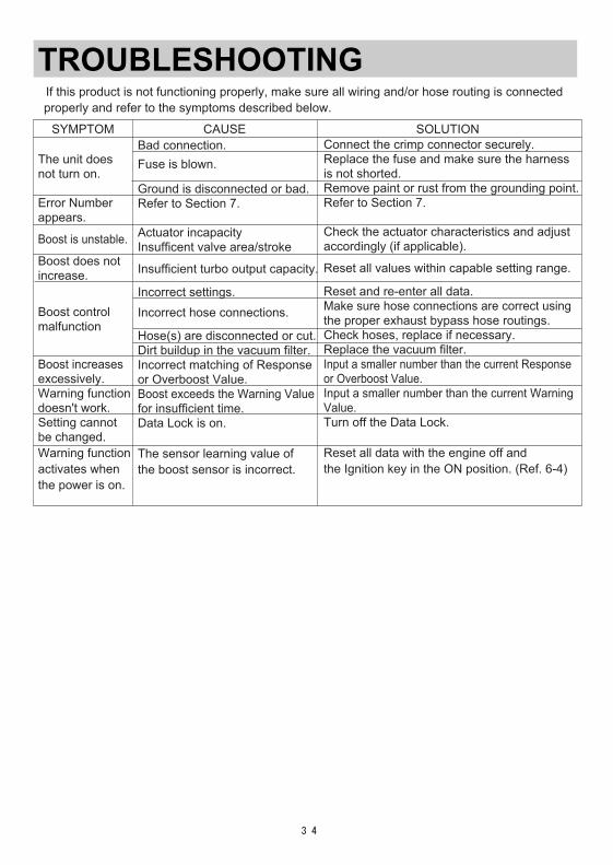
TROUBLESHOOTING If this product is not functioning properly, make sure all wiring and/or hose routing is connected properly and refer to the symptoms described below.
SYMPTOM CAUSE SOLUTION
The unit does not turn on.
Error Numberappears.
Boost is unstable.
Boost does notincrease.
Boost control malfunction
Boost increasesexcessively.Warning functiondoesn't work.Setting cannotbe changed.Warning functionactivates when the power is on.
Connect the crimp connector securely.Replace the fuse and make sure the harnessis not shorted.Remove paint or rust from the grounding point.Refer to Section 7.
Check the actuator characteristics and adjustaccordingly (if applicable).
Reset all values within capable setting range.
Reset and re-enter all data.Make sure hose connections are correct usingthe proper exhaust bypass hose routings.Check hoses, replace if necessary.Replace the vacuum filter.Input a smaller number than the current Responseor Overboost Value.Input a smaller number than the current WarningValue.Turn off the Data Lock.
Reset all data with the engine off and the Ignition key in the ON position. (Ref. 6-4)
Bad connection.Fuse is blown.
Ground is disconnected or bad.Refer to Section 7.
Actuator incapacityInsufficent valve area/stroke
Insufficient turbo output capacity.
Incorrect settings.Incorrect hose connections.
Hose(s) are disconnected or cut.Dirt buildup in the vacuum filter.Incorrect matching of Responseor Overboost Value.Boost exceeds the Warning Valuefor insufficient time.Data Lock is on.
The sensor learning value of the boost sensor is incorrect.
-35-
REPAIR SERVICEFor questions about this product or for any optional, missing, defective and/or damagedparts, please contact your Authorized HKS Dealer.
● Do not use this product if any unusual noises or scents are detected. Consult your Authorized HKS Dealer immediately. Otherwise, it may cause electrical shock or fire.
WARNING
CAUTION● Do not try to repair this product yourself. Consult your Authorized HKS Dealer.● If any unusual noises, scents, and/or vibrations are noticed while driving, please refer to the factory repair manual.
-36-
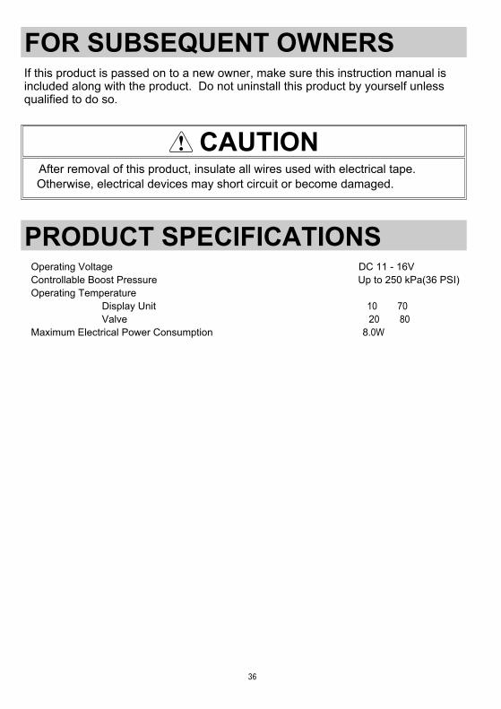
CAUTION●After removal of this product, insulate all wires used with electrical tape. Otherwise, electrical devices may short circuit or become damaged.
FOR SUBSEQUENT OWNERS If this product is passed on to a new owner, make sure this instruction manual is included along with the product. Do not uninstall this product by yourself unless qualified to do so.
PRODUCT SPECIFICATIONS●Operating Voltage ………………………………………………………………DC 11 - 16V●Controllable Boost Pressure …………………………………………………Up to 250 kPa(36 PSI)●Operating Temperature Display Unit …………………………………………………-10℃~70℃ Valve …………………………………………………………-20℃~80℃●Maximum Electrical Power Consumption …………………………………… 8.0W
-37-
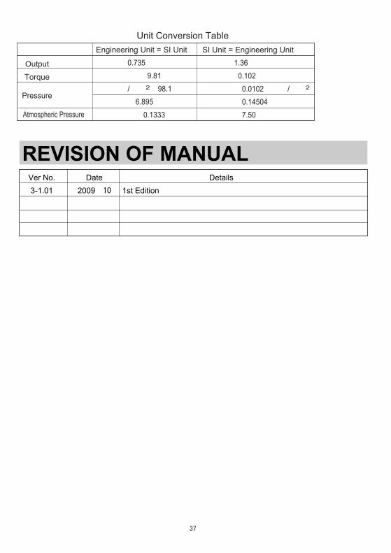
Date2009/10
Details1st Edition
REVISION OF MANUAL
Unit Conversion Table
OutputTorque
Pressure
Engineering Unit = SI Unit1PS=0.735kW1kgf・m=9.81N・m1kgf/cm2=98.1kPa1PSI=6.895kPa1mmHg=0.1333kPa
SI Unit = Engineering Unit1kW=1.36PS1N・m=0.102kgf・m1kPa=0.0102kgf/cm2
1kPa=0.14504PSI1kPa=7.50mmHg
Ver No.3-1.01
Atmospheric Pressure
Pursuing the Ultimate in Engine Performance and Efficiency.Produced by HKS Company Limited.
[禁無断複写・転載]©(株)エッチ・ケー・エス