Embed Size (px)
Citation preview
October / 2015 Page 1 CEX-O_CEX-U_Installation, Maintenance and User Instructions V1.04
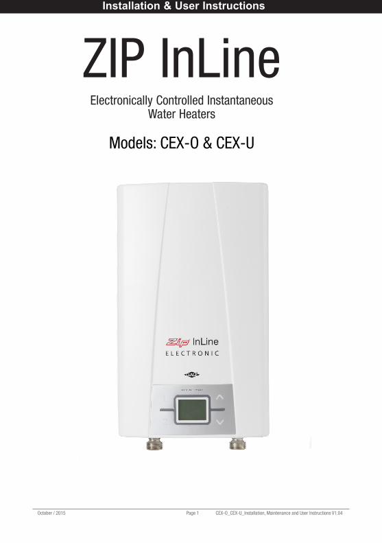
ZIP InLineElectronically Controlled Instantaneous
Water Heaters
Models: CEX-O & CEX-U
Installation & User Instructions
CEX-O_CEX-U, Maintenance and User Instructions V1.04 Page 2 October/ 2015
Please leave these instructions with the end user after installation.
To ensure you have the latest revision of this instruction manual, please visit www.zipheaters.co.uk to download the latest copy.
In order to preserve our environment we ask that you dispose of this product correctly.Please contact Zip Customer Service for advice on 0845 6 005 005 or 0345 6 005 005.
Contents
Description 3
Approvals 3
Safety information 4
WARNING 4
CAUTION 5
Technical data 6
Dimensions 7
Spare Parts 7
Installation 8
Requirements 8
Installation site 8
Installing the appliance 9
Electrical connection / Wiring diagram 10
Commissioning 11
Service menu 13
Operation 15
Maintenance and cleaning 17
Fault finding 18
Warranty 19
IMPORTANT:PLEASE READ THESE INSTRUCTIONS CAREFULLY. NOTE THE SAFE OPERATIONAL REQUIREMENTS, WARNINGS AND CAUTIONS. USE THIS PRODUCT CORRECTLY AND WITH CARE FOR THE PURPOSE FOR WHICH IT IS INTENDED. FAILURE TO DO SO MAY CAUSE DAMAGE AND/OR PERSONAL INJURY, AND WILL INVALIDATE THE WARRANTY. RETAIN THESE INSTRUCTIONS FOR FUTURE USE.
Index
October / 2015 Page 3 CEX-O_CEX-U_Installation, Maintenance and User Instructions V1.04
DescriptionZip InLine CEX-O and CEX-U instantaneous water heaters are micro-processor controlled, pressure resistant water heaters suitable for supplying hot water to one or more outlets.
The heating element switches on automatically when the hot water tap is opened and switches off automatically when the hot water tap is closed.
The electronic control system automatically regulates the power consumption depending on the supply water temperature and flow rate to achieve the required outlet temperature within the power limit of the appliance.
Power consumption is also regulated based on outlet temperature to ensure the required temperature is achieved exactly to the degree and irrespective of fluctuations in voltage and water pressure.
The power rating of the appliance can be selected as either 8.8kW or 6.6kW at 230V at the time of installation.
The required outlet temperature can be entered on a keypad within the range 20°C to 55°C and can be read off the digital display.
The maximum inlet temperature of 70°C is suitable for use with preheated water e.g. from solar heating systems.
ApprovalsZip InLine CEX-O and CEX-U are VDE approved to the LVD and EMC directives and are CE endorsed.
Zip InLine CEX-O and CEX-U have been examined, tested and found when correctly fitted to comply with the requirements of the United Kingdom Water Regulations / Byelaws (Scotland). The products are listed under the WRAS (Water Regulations Advisory Scheme) Water Fittings and Materials Directory.
General Product Description
CEX-O_CEX-U, Maintenance and User Instructions V1.04 Page 4 October/ 2015
Safety Information
WARNING• Installation, commissioning and maintenance of this appliance must only be carried out by a competent
installer who will then be responsible for adhering to all relevant standards and regulations.
• The front cover of the appliance must never be opened before disconnecting the appliance from the mains power supply.
• To protect the appliance, a circuit breaker or fuse must be fitted with a rating suitable for the nominal current of the appliance.
• The appliance must be permanently connected to the supply through an isolating switch with a contact separation of at least 3mm in all poles and be protected by a suitably rated RCD.
• The cross sectional area of the connection cable must be appropriate for the power rating and location of the appliance. See Technical Data.
• The connecting cable must be adequately secured.
• This appliance must be earthed at all times.
• Check that the power supply is switched off prior to electrical connection.
• The appliance, its wiring and piping must not be modified in any way.
• In case of malfunction isolate the power supply immediately. In case of leaks also isolate the water supply. Repairs must only be carried out by Zip Heaters (UK) Ltd or an authorised Zip service engineer.
• Temperatures in excess of approximately 43°C are perceived as hot, especially by children, and may cause a feeling of burning.
• This appliance can be used by children aged from 8 years and above and persons with reduced physical, sensory or mental capabilities or lack of experience and knowledge if they have been given supervision or instruction concerning the use of the appliance in a safe way and understand the hazards involved. Children shall not play with the appliance. Cleaning and user maintenance shall not be made by children without supervision.
• When the appliance has been in use for some time, the fittings may be very hot.
• If inlet temperature is up to 70°C (eg. fed from a solar supply) mixing with cold water will be required to ensure a safe temperature at the outlet.
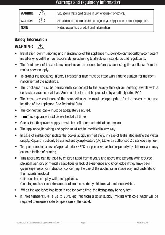
WARNING: Situations that could cause injury to yourself or others.
CAUTION: Situations that could cause damage to your appliance or other equipment.
NOTE: Notes, usage tips or additional information.
Warnings and regulatory information Warnings and regulatory information
October / 2015 Page 5 CEX-O_CEX-U_Installation, Maintenance and User Instructions V1.04
CAUTION• Optimum operation is ensured at a water flow pressure of 0.2 to 0.4 MPa (24 bar). The
appliance must not be subjected to pressure exceeding 1.0 MPa (10 bar).
• The appliance must only be used when correctly installed and in perfect working order.
• The appliance must be installed in a frost-free room and must never be exposed to frost.
• The CEX-O and CEX-U range is not intended for use with thermostatic mixing valves or taps. If thermostatic mixing valves or taps are to be used, their compatibility with the instantaneous water heater must be verified under site operating conditions.
• The appliance must be completely filled with water before being switched on.
• Before commissioning for the first time and each time the appliance or the piping system is emptied (e.g. due to work on the plumbing system or maintenance), the appliance must be vented by opening and closing the hot water tap until all air has been eliminated from the water heater and no more air emerges before re-connecting to the electrical supply.
• The appliance must only be used for heating potable water. The specific water resistance must not fall below the required value indicated on the rating plate. The appliance must not be used for any other purpose.
• Incoming water temperature must not exceed that stated in Technical data.
• The Zip InLine is intended for connection to mains supply only. In any other case please contact Zip on 0845 6 005 005 or 0345 6 005 005 for advice.
• Zip Heaters (UK) Ltd cannot be held liable for any damages caused by failure to observe these instructions.
Warnings and regulatory information
CEX-O_CEX-U, Maintenance and User Instructions V1.04 Page 6 October/ 2015
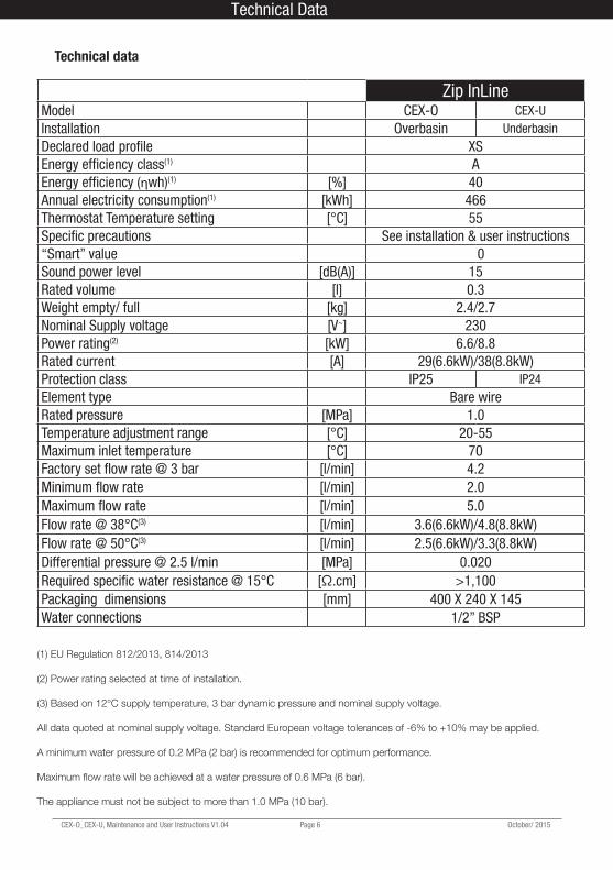
Technical data
(1) EU Regulation 812/2013, 814/2013
(2) Power rating selected at time of installation.
(3) Based on 12°C supply temperature, 3 bar dynamic pressure and nominal supply voltage.
All data quoted at nominal supply voltage. Standard European voltage tolerances of -6% to +10% may be applied.
A minimum water pressure of 0.2 MPa (2 bar) is recommended for optimum performance.
Maximum flow rate will be achieved at a water pressure of 0.6 MPa (6 bar).
The appliance must not be subject to more than 1.0 MPa (10 bar).
Zip InLineModel CEX-O CEX-UInstallation Overbasin UnderbasinDeclared load profile XSEnergy efficiency class(1) AEnergy efficiency (ηwh)(1) [%] 40Annual electricity consumption(1) [kWh] 466Thermostat Temperature setting [°C] 55Specific precautions See installation & user instructions“Smart” value 0Sound power level [dB(A)] 15Rated volume [l] 0.3Weight empty/ full [kg] 2.4/2.7Nominal Supply voltage [V~] 230Power rating(2) [kW] 6.6/8.8Rated current [A] 29(6.6kW)/38(8.8kW)Protection class IP25 IP24Element type Bare wireRated pressure [MPa] 1.0Temperature adjustment range [°C] 20-55Maximum inlet temperature [°C] 70Factory set flow rate @ 3 bar [l/min] 4.2Minimum flow rate [l/min] 2.0Maximum flow rate [l/min] 5.0Flow rate @ 38°C(3) [l/min] 3.6(6.6kW)/4.8(8.8kW)Flow rate @ 50°C(3) [l/min] 2.5(6.6kW)/3.3(8.8kW)Differential pressure @ 2.5 l/min [MPa] 0.020Required specific water resistance @ 15°C [Ω.cm] >1,100Packaging dimensions [mm] 400 X 240 X 145Water connections 1/2” BSP
Technical Data Spare Parts
October / 2015 Page 7 CEX-O_CEX-U_Installation, Maintenance and User Instructions V1.04
Spare Parts
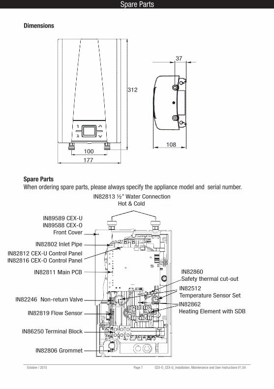
Dimensions
Spare PartsWhen ordering spare parts, please always specify the appliance model and serial number.
IN89589 CEX-UIN89588 CEX-O
Front Cover
IN82802 Inlet Pipe
IN82812 CEX-U Control PanelIN82816 CEX-O Control Panel
IN82811 Main PCB
IN82246 Non-return Valve
IN82819 Flow Sensor
IN86250 Terminal Block
IN82806 Grommet
IN82862Heating Element with SDB
IN82512Temperature Sensor Set
IN82860Safety thermal cut-out
IN82813 ½” Water Connection Hot & Cold
37
108100
177
312
CEX-O_CEX-U, Maintenance and User Instructions V1.04 Page 8 October/ 2015
InstallationRequirements
These instructions must be read and fully understood before commencing the installation. If in doubt, or in need of further guidance please ring Zip on 0845 6 005 005 or 0345 6 005 005.
• Zip InLine water heaters must be installed by a competent person familiar with electric instantaneous water heaters.
• Installations must comply fully with UK Water Regulations and any Local Authority requirements.• The electrical installation including earthing and cross bonding should comply with current IEE
regulations and any Local Authority requirements.• Zip InLine water heaters must be installed according to the specification on the rating plate and the
technical specifications.• To protect the appliance, a circuit breaker or fuse must be fitted with a rating suitable for the nomi nal
current of the appliance. (See Technical Data Section on page. 6).• The appliance must be permanently connected to the supply through an isolating switch with a
contact separation of at least 3mm in all poles and be protected by a suitably rated RCD.• The cross sectional area of the connection cable must be in accordance with the power rating of the
appliance and the specific requirements of the installation site up to a maximum cable size of 10mm2.• Take care to protect the wiring from damage during installation and ensure that the wiring is not
directly accessible after installation.• Check that the power supply is switched off prior to electrical connection.
The installation site must be free from frost at all times.• The appliance is designed for wall mounted installation. CEX-O for overbasin installation must be
installed with the water connections downward. CEX-U for underbasin installation must be installed with the water connections upward.
• The appliance complies with protection class IP25 for overbasin installation, protection class IP24 for underbasin installation and may therefore be installed in protection zone 1.
• The appliance complies with protection class IP25 for overbasin installation, protection class IP24 for underbasin installation and may therefore be installed in protection zone 1.
• For maintenance work a shut off valve should be installed in the water supply line to the heater.
• When considering the location of the heater, consideration should be given to the safe and visible disposal of any water resulting from leaks and seepage. This is particularly relevant when the heater is located in a cupboard or any concealed location. For guidance please call Zip Heaters (UK) Ltd on 0845 6 005 005 or 0345 6 005 005.
• Hot and cold water connecting pipes should be WRAS approved and of copper or steel construction. Plastic pipes may only be used if conforming to DIN 16893 Series 2. The hot water pipes must be thermally insulated.
• The specific resistance of the supply water must be at least 1100Ωcm at 15°C. The specific resistance can be checked with the local water supply company.
Installation Installation
Installation site
October / 2015 Page 9 CEX-O_CEX-U_Installation, Maintenance and User Instructions V1.04
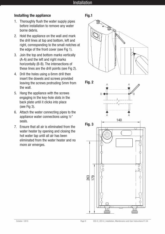
Installing the appliance1. Thoroughly flush the water supply pipes before installation to remove any water borne debris.
2. Hold the appliance on the wall and mark the drill lines at top and bottom, left and right, corresponding to the small notches at the edge of the front cover (see Fig 1).
3. Join the top and bottom marks vertically (A-A) and the left and right marks horizontally (B-B). The intersections of these lines are the drill points (see Fig 2).
4. Drill the holes using a 6mm drill then insert the dowels and screws provided leaving the screws protruding 5mm from the wall.
5. Hang the appliance with the screws engaging in the key-hole slots in the back plate until it clicks into place (see Fig 3).
6. Attach the water connecting pipes to the appliance water connections using ½” seals.
7. Ensure that all air is eliminated from the water heater by opening and closing the hot water tap until all air has been eliminated from the water heater and no more air emerges.
140
263
179
Fig.1
Fig. 3
Fig. 2
Installation
CEX-O_CEX-U, Maintenance and User Instructions V1.04 Page 10 October/ 2015
Electrical connectionThe electrical installation including earthing and cross bonding should comply with current IEE regulations and any Local Authority requirements.
The appliance must be installed according to the specification on the rating plate and the Technical specifications.
The appliance must be earthedThe appliance must be permanently connected to the electrical supply through an isolation switch having a contact separation of at least 3mm on all poles.
The cross sectional area of the connection cable must be in accordance with the power rating of the appliance and the specific requirements of the installation site up to a maximum cable size of 10mm2.
Take care to protect the wiring from damage during installation and ensure that any uninsulated wiring is not directly accessible after installation.
To protect the appliance, a circuit breaker must be fitted with a rating suitable for the nominal current of the appliance.
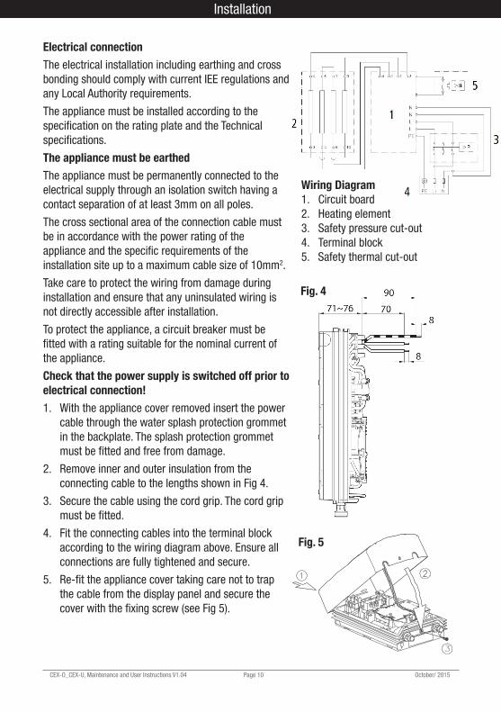
Check that the power supply is switched off prior to electrical connection!1. With the appliance cover removed insert the power cable through the water splash protection grommet in the backplate. The splash protection grommet must be fitted and free from damage.
2. Remove inner and outer insulation from the connecting cable to the lengths shown in Fig 4.
3. Secure the cable using the cord grip. The cord grip must be fitted.
4. Fit the connecting cables into the terminal block according to the wiring diagram above. Ensure all connections are fully tightened and secure.
5. Refit the appliance cover taking care not to trap the cable from the display panel and secure the cover with the fixing screw (see Fig 5).
Wiring Diagram1. Circuit board2. Heating element3. Safety pressure cut-out 4. Terminal block5. Safety thermal cut-out
Fig. 5
Fig. 4
Installation Commissioning
October / 2015 Page 11 CEX-O_CEX-U_Installation, Maintenance and User Instructions V1.04
Installation Commissioning
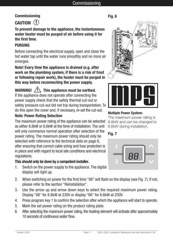
Multiple Power System:The maximum power rating is 8.8kW and can be changed to 6.6kW during installation.
Commissioning
CAUTION To prevent damage to the appliance, the instantaneous water heater must be purged of air before using it for the first time.PURGINGBefore connecting the electrical supply, open and close the hot water tap until the water runs smoothly and no more air emerges.
Note! Every time the appliance is drained (e.g. after work on the plumbing system, if there is a risk of frost or following repair work), the heater must be purged in this way before reconnecting the power supply.
WARNING! This appliance must be earthed. If the appliance does not operate after connecting the power supply check that the safety thermal cut-out or safety pressure cut-out did not trip during transportation. To do this open the cover and, if necessary, re-set the cut-out. Note: Power Rating SelectionThe maximum power rating of the appliance can be selected as either 8.8kW or 6.6kW at the time of installation. The unit will only commence normal operation after selection of the power rating. The maximum power rating should only be selected with reference to the technical data on page 6, after ensuring that correct cable sizing and fuse protection is in place and with regard to local site conditions and electrical regulations.This should only be done by a competent installer.1. Switch on the power supply to the appliance. The digital
display will light up.
Fig. 6
®
2. When switching on power for the first time “88” will flash on the display (see Fig .7). If not, please refer to the section “Reinstallation”.
3. Use the arrow up and arrow down keys to select the required maximum power rating. Display “88” for 8.8kW at 230V or display “66” for 6.6kW at 230V.
4. Press program key 1 to confirm the selection after which the appliance will start to operate.5. Mark the set power rating on the product rating plate.6. After selecting the maximum power rating, the heating element will activate after approximately
10 seconds of continuous water flow.
Fig. 7
CEX-O_CEX-U, Maintenance and User Instructions V1.04 Page 12 October/ 2015
Re-installationIf the appliance is to be re-commissioned under different installation conditions it may be necessary to alter the maximum power rating.
This should only be done by a competent installer.
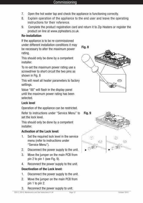
To re-set the maximum power rating use a screwdriver to short circuit the two pins as shown in Fig. 8
This will reset all heater parameters to factory settings.
Value “88” will flash in the display panel until the maximum power rating has been selected.
Lock levelOperation of the appliance can be restricted.
Refer to instructions under “Service Menu” to set the lock level.
This should only be done by a competent installer.
Activation of the Lock level:1. Set the required lock level in the service
menu (refer to instructions under “Service Menu”).
2. Disconnect the power supply to the unit.
3. Move the jumper on the main PCB from pin 2 to pin 1 (see Fig. 9).
4. Reconnect the power supply to the unit.
Deactivation of the Lock level:1. Disconnect the power supply to the unit.
2. Move the jumper on the main PCB from pin 1 to pin 2.
3. Reconnect the power supply to unit.
Fig. 8
7. Open the hot water tap and check the appliance is functioning correctly.8. Explain operation of the appliance to the end user and leave the operating
instructions for their reference.9. Complete the product registration card and return it to Zip Heaters or register the
product on line at www.zipheaters.co.uk
Fig. 9
Commissioning Servicing
October / 2015 Page 13 CEX-O_CEX-U_Installation, Maintenance and User Instructions V1.04
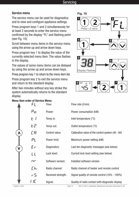
Service menuThe service menu can be used for diagnostics and to view and configure appliance settings.
Press program keys 1 and 2 simultaneously for at least 2 seconds to enter the service menu confirmed by the display “FL” and flashing point (see Fig. 10).
Scroll between menu items in the service menu using the arrow up and arrow down keys.
Press program key 1 to display the value of the currently selected menu item. The value flashes in the display.
The values of some menu items can be dislayed by using the arrow up and arrow down keys.
Press program key 1 to return to the menu item list.
Press program key 2 to exit the service menu and return to the standard display.
After two minutes without any key stroke the system automatically returns to the standard display.Menu item order of Service Menu:
Flow: Flow rate (l/min)
Power: Power consumption (kW)
Temp in: Inlet temperature (°C)
Temp out: Outlet temperature (°C)
Control value: Calibration value of the control system (40 - 60)
Power limit: Maximum power setting (kW)
Diagnostics: Last ten diagnostic messages (see below)
Lock level: Current lock level setting (see below)
Software version: Installed software version
Radio channel: Radio channel of heater and remote control
Received strength: Signal quality of remote control (10% - 100%)
Signal: Quality of radio contact with diagnostic display
v
v
Press >2 secs
Display Flashes
1 2
4
5
789
3
6
Fig. 10
Servicing
CEX-O_CEX-U, Maintenance and User Instructions V1.04 Page 14 October/ 2015
“Er”: DiagnosticsThe last ten diagnostic messages can be displayed.
Pressing program key 1 displays the current error code. A key explaining the error codes can be found inside the front cover of the appliance.
The arrow up and arrow down keys can be used to view the last ten error codes displayed in chronological order from “0” to “9” alongside the corresponding error code with “0” being the most recent.
“LL”: Lock levelThe operating mode of the appliance can be restricted.
Setting options:“0” No restriction (factory setting).
“1” Disables “Reset to factory setting”. Parameters can be viewed but not modified in service menu.
“2” As “1”, additionally service menu cannot be displayed.
“3” As “2”, additionally program 1 and 2 set temperature values cannot be changed
“4” As “3”, additionally set temperature value on appliance cannot be changed.
Note: when lock level 1, 2, 3 or 4 is selected the system parameters cannot be modified in the service menu.
In order to modify system parameters it is necessary to remove the jumper from the main PCB as described under “Deactivation of the Lock level”.
Servicing Operation
October / 2015 Page 15 CEX-O_CEX-U_Installation, Maintenance and User Instructions V1.04
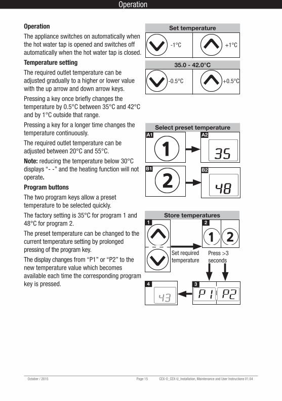
OperationThe appliance switches on automatically when the hot water tap is opened and switches off automatically when the hot water tap is closed.
Temperature settingThe required outlet temperature can be adjusted gradually to a higher or lower value with the up arrow and down arrow keys.
Pressing a key once briefly changes the temperature by 0.5°C between 35°C and 42°C and by 1°C outside that range.
Pressing a key for a longer time changes the temperature continuously.
The required outlet temperature can be adjusted between 20°C and 55°C.
Note: reducing the temperature below 30°C displays “- -” and the heating function will not operate.Program buttonsThe two program keys allow a preset temperature to be selected quickly.
The factory setting is 35°C for program 1 and 48°C for program 2.
The preset temperature can be changed to the current temperature setting by prolonged pressing of the program key.
The display changes from “P1” or “P2” to the new temperature value which becomes available each time the corresponding program key is pressed.
Set temperature
-1°C +1°C
35.0 - 42.0°C
-0.5°C +0.5°C
A1 A2
B1 B2
Select preset temperature
Store temperatures2
34
1
Set required temperature
Press >3 seconds
Operation
CEX-O_CEX-U, Maintenance and User Instructions V1.04 Page 16 October/ 2015
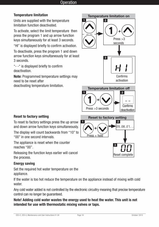
Temperature limitationUnits are supplied with the temperature limitation function deactivated.
To activate, select the limit temperature then press the program 1 and up arrow function keys simultaneously for at least 3 seconds.
“HI” is displayed briefly to confirm activation.
To deactivate, press the program 1 and down arrow function keys simultaneously for at least 3 seconds.
“ “ is displayed briefly to confirm deactivation.
Note: Programmed temperature settings may need to be reset after deactivating temperature limitation.
Reset to factory settingTo reset to factory settings press the up arrow and down arrow function keys simultaneously.
The display will count backwards from “10” to “00” in one second intervals.
The appliance is reset when the counter reaches “00”.
Releasing the function keys earlier will cancel the process.
Temperature limitation on
3
1 2
Press >3 seconds
Confirms activation
+
Temperature limitation off 1 2
Press >3 secondsConfirms
deactivation
+
Reset to factory setting2
3
1
Press + hold
Reset complete
+
Energy savingSet the required hot water temperature on the appliance.
If the water is too hot reduce the temperature on the appliance instead of mixing with cold water.
Any cold water added is not controlled by the electronic circuitry meaning that precise temperature control can no longer be guaranteed.
Note! Adding cold water wastes the energy used to heat the water. This unit is not intended for use with thermostatic mixing valves or taps.
Operation Maintenance
October / 2015 Page 17 CEX-O_CEX-U_Installation, Maintenance and User Instructions V1.04
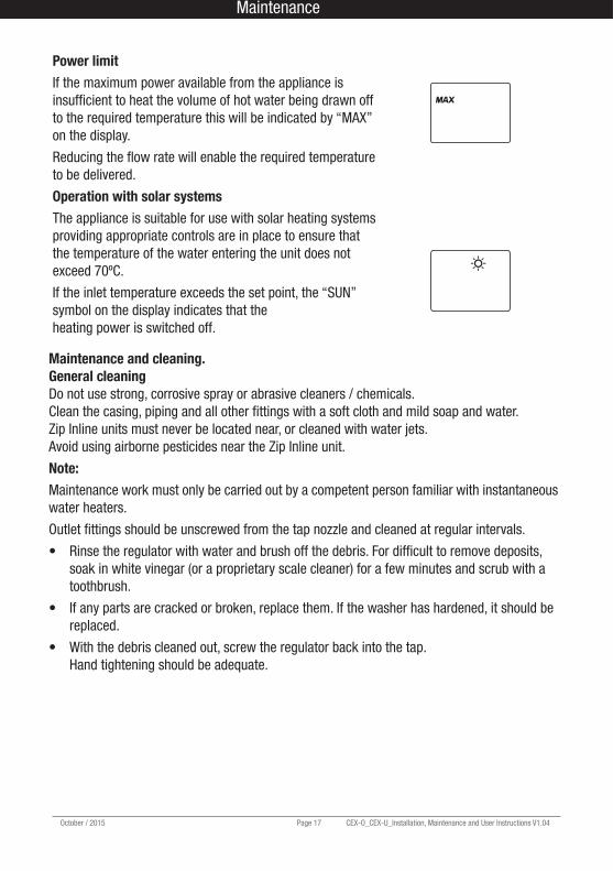
Power limitIf the maximum power available from the appliance is insufficient to heat the volume of hot water being drawn off to the required temperature this will be indicated by “MAX” on the display.
Reducing the flow rate will enable the required temperature to be delivered.
Operation with solar systemsThe appliance is suitable for use with solar heating systems providing appropriate controls are in place to ensure that the temperature of the water entering the unit does not exceed 70ºC.
If the inlet temperature exceeds the set point, the “SUN” symbol on the display indicates that the heating power is switched off.
Maintenance and cleaning.General cleaningDo not use strong, corrosive spray or abrasive cleaners / chemicals. Clean the casing, piping and all other fittings with a soft cloth and mild soap and water. Zip Inline units must never be located near, or cleaned with water jets. Avoid using airborne pesticides near the Zip Inline unit.
Note:Maintenance work must only be carried out by a competent person familiar with instantaneous water heaters.
Outlet fittings should be unscrewed from the tap nozzle and cleaned at regular intervals.
• Rinse the regulator with water and brush off the debris. For difficult to remove deposits, soak in white vinegar (or a proprietary scale cleaner) for a few minutes and scrub with a toothbrush.
• If any parts are cracked or broken, replace them. If the washer has hardened, it should be replaced.
• With the debris cleaned out, screw the regulator back into the tap. Hand tightening should be adequate.
Maintenance
CEX-O_CEX-U, Maintenance and User Instructions V1.04 Page 18 October/ 2015
Fault findingRepairs should only be carried out by competent persons familiar with electric instantaneous water heaters.
All service work should be performed by an authorized Zip service engineer – for details of the full range of services available call Zip Service on 0845 6 005 005 or 0345 6 005 005.
When calling for service, please always specify the appliance model and serial number.
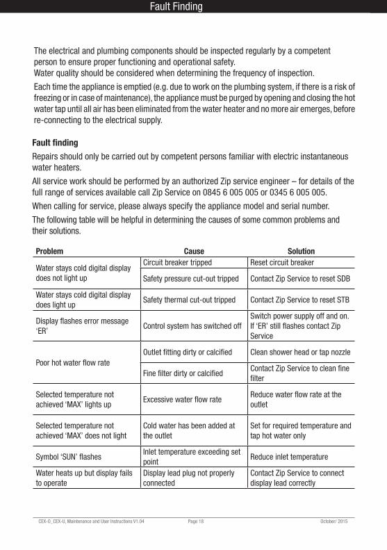
The following table will be helpful in determining the causes of some common problems and their solutions.
Problem Cause Solution
Water stays cold digital display does not light up
Circuit breaker tripped Reset circuit breaker
Safety pressure cut-out tripped Contact Zip Service to reset SDB
Water stays cold digital display does light up
Safety thermal cut-out tripped Contact Zip Service to reset STB
Display flashes error message ‘ER’
Control system has switched offSwitch power supply off and on. If ‘ER’ still flashes contact Zip Service
Poor hot water flow rateOutlet fitting dirty or calcified Clean shower head or tap nozzle
Fine filter dirty or calcifiedContact Zip Service to clean fine filter
Selected temperature not achieved ‘MAX’ lights up
Excessive water flow rateReduce water flow rate at the outlet
Selected temperature not achieved ‘MAX’ does not light
Cold water has been added at the outlet
Set for required temperature and tap hot water only
Symbol ‘SUN’ flashesInlet temperature exceeding set point
Reduce inlet temperature
Water heats up but display fails to operate
Display lead plug not properly connected
Contact Zip Service to connect display lead correctly
The electrical and plumbing components should be inspected regularly by a competent person to ensure proper functioning and operational safety. Water quality should be considered when determining the frequency of inspection.
Each time the appliance is emptied (e.g. due to work on the plumbing system, if there is a risk of freezing or in case of maintenance), the appliance must be purged by opening and closing the hot water tap until all air has been eliminated from the water heater and no more air emerges, before re-connecting to the electrical supply.
Fault Finding Warranty
October / 2015 Page 19 CEX-O_CEX-U_Installation, Maintenance and User Instructions V1.04
The Zip appliance you have chosen is precisionbuilt from the finest materials available and should give many years of trouble free service.
Certain warranties may be implied by law into your contract with Zip. The warranty provided below is additional to these implied warranties and nothing set out below shall limit your statutory rights or rights at law.
Zip Heaters (UK) Ltd warrants that, should any part fail within 12 calendar months of installation, that part will be repaired or replaced free of charge by Zip or its Distributor or Service Provider, except as set out below, provided the appliance is installed and used strictly in accordance with the instructions supplied, and that failure is not due to accident, misuse, abuse, unsuitable water conditions, or to any alteration, modification or repair by any party not expressly nominated by Zip.
No costs are payable by the customer other than any mileage or travelling-time charges incurred by a Zip Service Provider or the cost of removal, cartage and re-installation of any component of the appliance if it needs to be returned for repair to Zip or its Distributor.
This warranty does not cover damage resulting from non-operation of the appliance or consequential damage to any other goods, furnishings or property.
Zip does not exclude, restrict or modify any liability that cannot be excluded, restricted or modified or which cannot, except to a limited extent, be excluded, restricted or modified as between the owner or user and Zip under the laws applicable.
Furthermore, this warranty does not displace any statutory warranty, but, to the extent to which Zip is entitled to do so, the liability of Zip under any statutory warranty will be limited at Zip’s option to the replacement of the appliance or supply of equivalent appliance, the payment of the cost of replacing the appliance or acquiring an equivalent appliance, or the payment of the cost of having the appliance repaired or the repair of the appliance.
NOTE: It is our policy to continually improve products and as such we reserve the right to alter data, specifications and component parts without prior notice.
To ensure you have the latest revision of this instruction manual, please visit www.zipheaters.co.uk to download the latest copy.
IMPORTANT: No liability is accepted for incorrect use of this product.
The use of this crossed out wheeled bin logo indicates that this product needs to be disposed of separately to any other household waste.Within each of the European Union member countries, provisions have been made for the collection and recycling of unwanted electrical and electronic equipment.In order to preserve our environment we ask that you dispose of this product correctly. Please contact Zip Customer Service for advice on 0845 6 005 005 or 0345 6 005 005.
Warranty
End of Life Disposal
CEX-O_CEX-U, Maintenance and User Instructions V1.04 Page 20 October/ 2015
Zip Heaters (UK) Ltd14 Bertie Ward WayDerehamNorfolkNR19 1TE
Telephone: 0845 6 005 005Mobile: 0345 6 005 005Fax: 01362 692448Web: www.zipheaters.co.uk
The terms ‘Zip’ and ‘InLine’ are registered trademarks
999120-2546