Embed Size (px)
Citation preview
H3C MSR 20-1X Routers Installation Guide
Hangzhou H3C Technologies Co., Ltd. http://www.h3c.com Document version: 20101217-C-1.04
Copyright © 2006-2010, Hangzhou H3C Technologies Co., Ltd. and its licensors
All rights reserved
No part of this manual may be reproduced or transmitted in any form or by any means without prior written consent of Hangzhou H3C Technologies Co., Ltd.
Trademarks
H3C, , Aolynk, , H3Care,
, TOP G, , IRF, NetPilot, Neocean, NeoVTL, SecPro, SecPoint, SecEngine, SecPath, Comware, Secware, Storware, NQA, VVG, V2G, VnG, PSPT, XGbus, N-Bus, TiGem, InnoVision and HUASAN are trademarks of Hangzhou H3C Technologies Co., Ltd.
All other trademarks that may be mentioned in this manual are the property of their respective owners
Notice
The information in this document is subject to change without notice. Every effort has been made in the preparation of this document to ensure accuracy of the contents, but all statements, information, and recommendations in this document do not constitute the warranty of any kind, express or implied.
Environmental protection
This product has been designed to comply with the environmental protection requirements. The storage, use, and disposal of this product must meet the applicable national laws and regulations.
Preface
The H3C MSR 20-1X Routers Installation Guide describes how to install the H3C MSR 20-1X Routers, maintain software and hardware of the router, and solve problems you may encounter during the installation process.
This preface includes:
• Audience
• Conventions
• About the H3C MSR documentation set
• Obtaining documentation
• Technical support
• Documentation feedback
Audience This documentation is intended for:
• Network planners
• Field technical support and servicing engineers
• Network administrators working with the MSR Series
Conventions This section describes the conventions used in this documentation set.
Symbols
Convention Description
WARNING An alert that calls attention to important information that if not understood or followed can result in personal injury.
CAUTION An alert that calls attention to important information that if not understood or followed can result in data loss, data corruption, or damage to hardware or software.
IMPORTANT An alert that calls attention to essential information.
NOTE An alert that contains additional or supplementary information.
TIP An alert that provides helpful information.
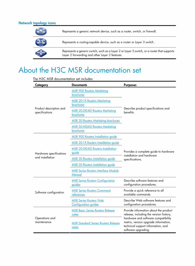
Network topology icons
Represents a generic network device, such as a router, switch, or firewall.
Represents a routing-capable device, such as a router or Layer 3 switch.
Represents a generic switch, such as a Layer 2 or Layer 3 switch, or a router that supports Layer 2 forwarding and other Layer 2 features.
About the H3C MSR documentation set The H3C MSR documentation set includes:
Category Documents Purposes
MSR 900 Routers Marketing brochures
MSR 20-1X Routers Marketing brochures
MSR 20-2X[40] Routers Marketing brochures
MSR 30 Routers Marketing brochures
Product description and specifications
MSR 50-40[60] Routers Marketing brochures
Describe product specifications and benefits.
MSR 900 Routers Installation guide
MSR 20-1X Routers Installation guide
MSR 20-2X[40] Routers Installation guide
MSR 30 Routers Installation guide
MSR 50 Routers Installation guide
Hardware specifications and installation
MSR Series Routers Interface Module Manual
Provides a complete guide to hardware installation and hardware specifications.
MSR Series Routers Configuration guides
Describe software features and configuration procedures.
MSR Series Routers Command references
Provide a quick reference to all available commands.
Software configuration
MSR Series Routers Web Configuration guides
Describe Web software features and configuration procedures.
MSR Basic Series Routers Release notes
Operations and maintenance MSR Standard Series Routers Release
notes
Provide information about the product release, including the version history, hardware and software compatibility matrix, version upgrade information, technical support information, and software upgrading.
Obtaining documentation You can access the most up-to-date H3C product documentation on the World Wide Web at http://www.h3c.com.
Click the links on the top navigation bar to obtain different categories of product documentation:
[Technical Support & Documents > Technical Documents] – Provides hardware installation, software upgrading, and software feature configuration and maintenance documentation.
[Products & Solutions] – Provides information about products and technologies, as well as solutions.
[Technical Support & Documents > Software Download] – Provides the documentation released with the software version.
Technical support [email protected]
http://www.h3c.com
Documentation feedback You can e-mail your comments about product documentation to [email protected].
We appreciate your comments.
i
Contents
Overview ······································································································································································ 1 Introduction ········································································································································································1 Physical Description of the MSR 20-1X Routers ·············································································································1
Hardware Specifications ·········································································································································1 MSR 20-10 Router····················································································································································3 MSR 20-11 Router····················································································································································4 MSR 20-12 Router····················································································································································6 MSR 20-13 Router····················································································································································8 MSR 20-15 Router················································································································································· 10
Generic Modules···························································································································································· 11 SICs and DSICs ····················································································································································· 12
Installation Preparations ············································································································································13 Requirements on Environment ······································································································································· 13
Requirements on Temperature and Humidity ····································································································· 13 Requirements on Cleanness·································································································································· 13 Requirements on Electrostatic Discharge Prevention·························································································· 14 Requirements on Electromagnetic Environment ·································································································· 14 Requirements on Lightning Protection·················································································································· 14 Checking the Rack················································································································································· 15
Safety Precautions ·························································································································································· 15 Installation Tools, Meters and Equipment ···················································································································· 15
Installation···································································································································································17 Installation Flowchart ····················································································································································· 17 Installing the Cabinet ····················································································································································· 17 Installing the Router························································································································································ 17
Installing the Router on a Workbench················································································································· 18 Installing the Router on a Cabinet ······················································································································· 18 Installing the Router on a Wall ···························································································································· 19
Installing Generic Modules ··········································································································································· 20 Connecting the PGND Cable ······································································································································· 20 Connecting the Power Cord·········································································································································· 21
Power Socket and PGND ····································································································································· 21 Connecting the AC Power Cord ·························································································································· 21
Installing Antennas ························································································································································· 22 Connecting the Console Terminal ································································································································ 22 Fixed Interfaces ······························································································································································ 23
Layer 3 Ethernet Interface····································································································································· 23 Connecting the AUX Interface to a Modem ······································································································· 26
Installing and Removing the Slide Rails ······················································································································· 27 Slide Rails······························································································································································· 27 Installing the Slide Rails ········································································································································ 27 Removing the Slide Rails······································································································································· 28
Installing the Security Lock ············································································································································ 28 Verifying Installation ······················································································································································ 28
Startup and Configuration·········································································································································29 Startup ············································································································································································· 29
Setting Up the Configuration Environment·········································································································· 29
ii
Powering on the Router········································································································································· 31 Startup Process······················································································································································· 32
Configuration Fundamentals ········································································································································· 32 Command Line Interface······································································································································· 33 Slot Arrangement and Rules for Numbering Interfaces····················································································· 34
Software Maintenance···············································································································································35 Introduction ····································································································································································· 35
Files Managed by the Router ······························································································································· 35 Software Maintenance Methods·························································································································· 36
Maintaining Application Program and Configuration Through Command Lines···················································· 37 Maintaining the Router Through TFTP Server ····································································································· 38 Maintaining the Router Through FTP Server ······································································································· 40
BootWare Menu····························································································································································· 43 Main BootWare Menu·········································································································································· 43 BootWare Submenus ············································································································································ 45
Upgrading an Application Program Through an Ethernet Interface········································································· 47 Configuring Ethernet Interface Parameters ········································································································· 48 Upgrading Procedure ··········································································································································· 49
Upgrading BootWare Through Ethernet Interface······································································································ 51 Upgrading BootWare Through Serial Interface·········································································································· 51
XModem Protocol Overview ································································································································ 51 Modifying Serial Interface Parameters················································································································ 52 Upgrading BootWare ··········································································································································· 53
Upgrading an Application Program Through a Serial Interface··············································································· 55 Maintaining Application and Configuration Files ······································································································ 55 Dealing with Password Loss ·········································································································································· 57
User Password Loss ··············································································································································· 57 BootWare Password Loss ····································································································································· 58 Super Password Loss ············································································································································· 58
Backing Up and Restoring BootWare·························································································································· 59
Hardware Maintenance ············································································································································60 Preparing Tools ······························································································································································ 60 Opening the Chassis Cover·········································································································································· 60 Internal Structure····························································································································································· 61 Replacing a VPM Card ················································································································································· 61
Structure of VPM Card·········································································································································· 61 VPM Slot ································································································································································· 62 Installing/Removing a VPM Card························································································································ 62
Setting the Fixed E1 Interface Impedance ··················································································································· 63
Troubleshooting··························································································································································65 Troubleshooting the Power System······························································································································· 65 Troubleshooting the Configuration System·················································································································· 65 Troubleshooting Application Software Upgrade ········································································································ 66
Index ···········································································································································································68
1
Overview
Introduction The MSR 20-1X routers are multifunctional access routers which are oriented to small and medium business (SMB), enterprise branches, and home offices, and are designed to serve high-quality orderwire and commercial networks. High-quality orderwire and commercial networks need to satisfy the requirements for broadband access, wireless access, voice access, VPN, and QoS. In addition, the network devices require high performance, stability, security, and manageability. MSR 20-1X routers are cost effective. They provide different integrated communication interfaces for different communication links and also provide an SIC/DSIC slot for expansion.
The MSR 20-1X routers include MSR 20-10, MSR 20-11, MSR 20-12, MSR 20-13, and MSR 20-15. All of them can be placed on a tabletop, or installed on a wall or in 19-inch standard cabinet. The following sections will give you more details about these four models.
Physical Description of the MSR 20-1X Routers
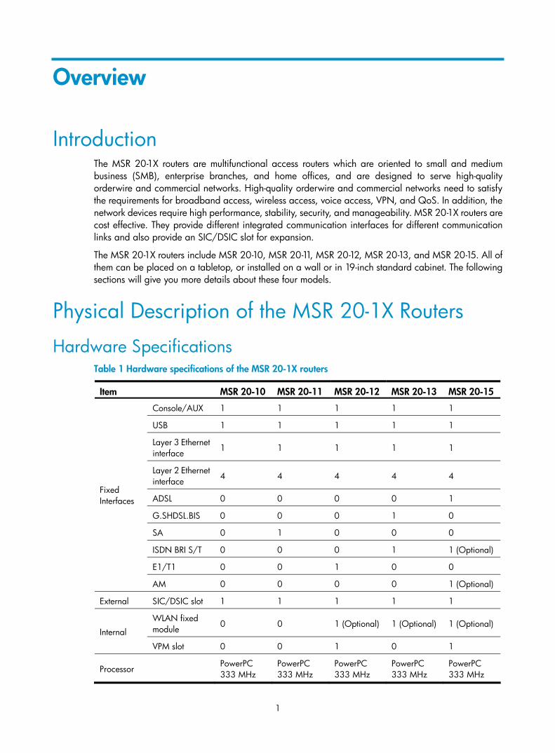
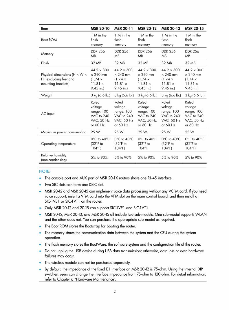
Hardware Specifications Table 1 Hardware specifications of the MSR 20-1X routers
Item MSR 20-10 MSR 20-11 MSR 20-12 MSR 20-13 MSR 20-15
Console/AUX 1 1 1 1 1
USB 1 1 1 1 1
Layer 3 Ethernet interface 1 1 1 1 1
Layer 2 Ethernet interface
4 4 4 4 4
ADSL 0 0 0 0 1
G.SHDSL.BIS 0 0 0 1 0
SA 0 1 0 0 0
ISDN BRI S/T 0 0 0 1 1 (Optional)
E1/T1 0 0 1 0 0
Fixed Interfaces
AM 0 0 0 0 1 (Optional)
External SIC/DSIC slot 1 1 1 1 1
WLAN fixed module 0 0 1 (Optional) 1 (Optional) 1 (Optional)
Internal
VPM slot 0 0 1 0 1
Processor PowerPC 333 MHz
PowerPC 333 MHz
PowerPC 333 MHz
PowerPC 333 MHz
PowerPC 333 MHz
2
Item MSR 20-10 MSR 20-11 MSR 20-12 MSR 20-13 MSR 20-15
Boot ROM 1 M in the flash memory
1 M in the flash memory
1 M in the flash memory
1 M in the flash memory
1 M in the flash memory
Memory DDR 256 MB
DDR 256 MB
DDR 256 MB
DDR 256 MB
DDR 256 MB
Flash 32 MB 32 MB 32 MB 32 MB 32 MB
Physical dimensions (H × W × D) (excluding feet and mounting brackets)
44.2 × 300 × 240 mm (1.74 × 11.81 × 9.45 in.)
44.2 × 300 × 240 mm (1.74 × 11.81 × 9.45 in.)
44.2 × 300 × 240 mm (1.74 × 11.81 × 9.45 in.)
44.2 × 300 × 240 mm (1.74 × 11.81 × 9.45 in.)
44.2 × 300 × 240 mm (1.74 × 11.81 × 9.45 in.)
Weight 3 kg (6.6 lb.) 3 kg (6.6 lb.) 3 kg (6.6 lb.) 3 kg (6.6 lb.) 3 kg (6.6 lb.)
AC input
Rated voltage range: 100 VAC to 240 VAC, 50 Hz or 60 Hz
Rated voltage range: 100 VAC to 240 VAC, 50 Hz or 60 Hz
Rated voltage range: 100 VAC to 240 VAC, 50 Hz or 60 Hz
Rated voltage range: 100 VAC to 240 VAC, 50 Hz or 60 Hz
Rated voltage range: 100 VAC to 240 VAC, 50 Hz or 60 Hz
Maximum power consumption 25 W 25 W 25 W 25 W 25 W
Operating temperature 0°C to 40°C (32°F to 104°F)
0°C to 40°C (32°F to 104°F)
0°C to 40°C (32°F to 104°F)
0°C to 40°C (32°F to 104°F)
0°C to 40°C (32°F to 104°F)
Relative humidity (non-condensing) 5% to 90% 5% to 90% 5% to 90% 5% to 90% 5% to 90%
NOTE:
• The console port and AUX port of MSR 20-1X routers share one RJ-45 interface.
• Two SIC slots can form one DSIC slot.
• MSR 20-12 and MSR 20-15 can implement voice data processing without any VCPM card. If you needvoice support, insert a VPM card into the VPM slot on the main control board, and then install a SIC-1VE1 or SIC-1VT1 on the router.
• Only MSR 20-12 and 20-15 can support SIC-1VE1 and SIC-1VT1.
• MSR 20-12, MSR 20-13, and MSR 20-15 all include two sub-models. One sub-model supports WLANand the other does not. You can purchase the appropriate sub-model as required.
• The Boot ROM stores the Bootstrap for booting the router.
• The memory stores the communication data between the system and the CPU during the system operation.
• The flash memory stores the BootWare, the software system and the configuration file of the router.
• Do not unplug the USB device during USB data transmission; otherwise, data loss or even hardware failures may occur.
• The wireless module can not be purchased separately.
• By default, the impedance of the fixed E1 interface on MSR 20-12 is 75-ohm. Using the internal DIP switches, users can change the interface impedance from 75-ohm to 120-ohm. For detail information, refer to Chapter 6 “Hardware Maintenance”.
3
MSR 20-10 Router Appearance
1. Front panel
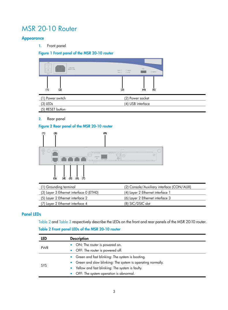
Figure 1 Front panel of the MSR 20-10 router
(1) Power switch (2) Power socket (3) LEDs (4) USB interface (5) RESET button
2. Rear panel
Figure 2 Rear panel of the MSR 20-10 router
(1) Grounding terminal (2) Console/Auxiliary interface (CON/AUX) (3) Layer 3 Ethernet interface 0 (ETH0) (4) Layer 2 Ethernet interface 1 (5) Layer 2 Ethernet interface 2 (6) Layer 2 Ethernet interface 3 (7) Layer 2 Ethernet interface 4 (8) SIC/DSIC slot
Panel LEDs
Table 2 and Table 3 respectively describe the LEDs on the front and rear panels of the MSR 20-10 router.
Table 2 Front panel LEDs of the MSR 20-10 router
LED Description
PWR • ON: The router is powered on. • OFF: The router is powered off.
SYS
• Green and fast blinking: The system is booting. • Green and slow blinking: The system is operating normally. • Yellow and fast blinking: The system is faulty. • OFF: The system operation is abnormal.
4
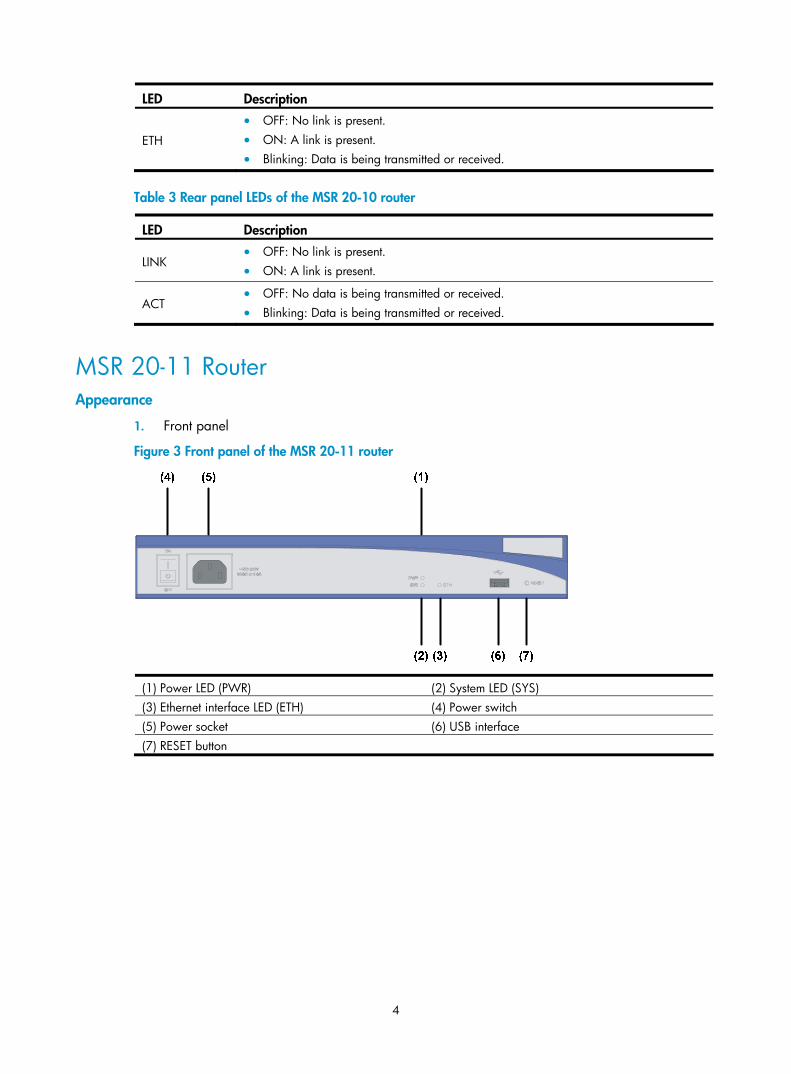
LED Description
ETH
• OFF: No link is present. • ON: A link is present. • Blinking: Data is being transmitted or received.
Table 3 Rear panel LEDs of the MSR 20-10 router
LED Description
LINK • OFF: No link is present. • ON: A link is present.
ACT • OFF: No data is being transmitted or received. • Blinking: Data is being transmitted or received.
MSR 20-11 Router Appearance
1. Front panel
Figure 3 Front panel of the MSR 20-11 router
(1) Power LED (PWR) (2) System LED (SYS) (3) Ethernet interface LED (ETH) (4) Power switch (5) Power socket (6) USB interface (7) RESET button
5
2. Rear panel
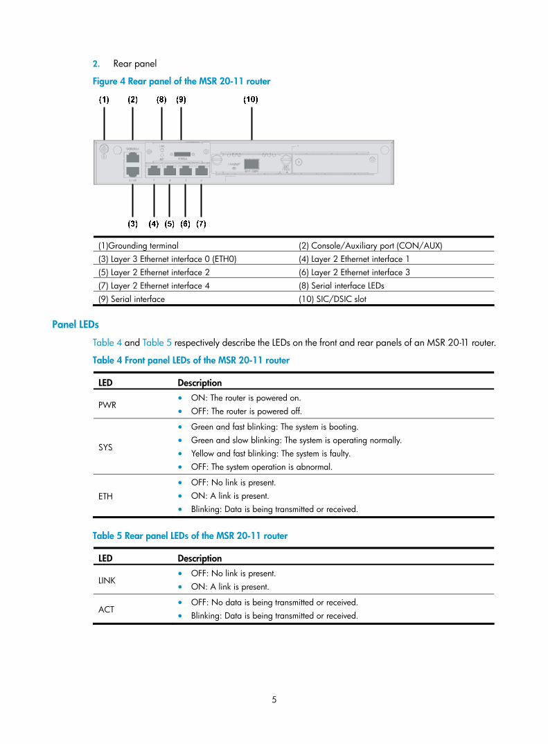
Figure 4 Rear panel of the MSR 20-11 router
(1)Grounding terminal (2) Console/Auxiliary port (CON/AUX) (3) Layer 3 Ethernet interface 0 (ETH0) (4) Layer 2 Ethernet interface 1 (5) Layer 2 Ethernet interface 2 (6) Layer 2 Ethernet interface 3 (7) Layer 2 Ethernet interface 4 (8) Serial interface LEDs (9) Serial interface (10) SIC/DSIC slot
Panel LEDs
Table 4 and Table 5 respectively describe the LEDs on the front and rear panels of an MSR 20-11 router.
Table 4 Front panel LEDs of the MSR 20-11 router
LED Description
PWR • ON: The router is powered on. • OFF: The router is powered off.
SYS
• Green and fast blinking: The system is booting. • Green and slow blinking: The system is operating normally. • Yellow and fast blinking: The system is faulty. • OFF: The system operation is abnormal.
ETH
• OFF: No link is present. • ON: A link is present. • Blinking: Data is being transmitted or received.
Table 5 Rear panel LEDs of the MSR 20-11 router
LED Description
LINK • OFF: No link is present. • ON: A link is present.
ACT • OFF: No data is being transmitted or received. • Blinking: Data is being transmitted or received.
6
MSR 20-12 Router Appearance
1. Front panel
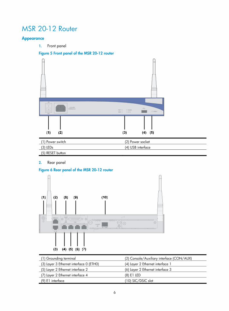
Figure 5 Front panel of the MSR 20-12 router
(1) Power switch (2) Power socket (3) LEDs (4) USB interface (5) RESET button
2. Rear panel
Figure 6 Rear panel of the MSR 20-12 router
(1) Grounding terminal (2) Console/Auxiliary interface (CON/AUX) (3) Layer 3 Ethernet interface 0 (ETH0) (4) Layer 2 Ethernet interface 1 (5) Layer 2 Ethernet interface 2 (6) Layer 2 Ethernet interface 3 (7) Layer 2 Ethernet interface 4 (8) E1 LED (9) E1 interface (10) SIC/DSIC slot
7
Panel LEDs
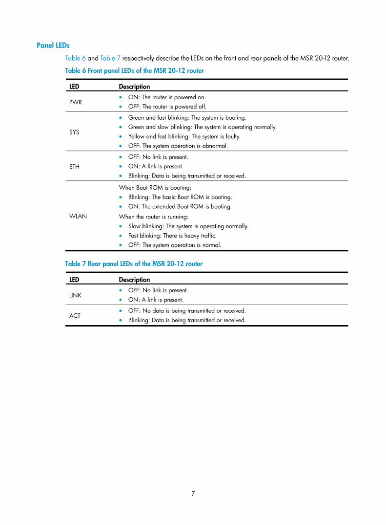
Table 6 and Table 7 respectively describe the LEDs on the front and rear panels of the MSR 20-12 router.
Table 6 Front panel LEDs of the MSR 20-12 router
LED Description
PWR • ON: The router is powered on. • OFF: The router is powered off.
SYS
• Green and fast blinking: The system is booting. • Green and slow blinking: The system is operating normally. • Yellow and fast blinking: The system is faulty. • OFF: The system operation is abnormal.
ETH
• OFF: No link is present. • ON: A link is present. • Blinking: Data is being transmitted or received.
WLAN
When Boot ROM is booting: • Blinking: The basic Boot ROM is booting. • ON: The extended Boot ROM is booting.
When the router is running: • Slow blinking: The system is operating normally. • Fast blinking: There is heavy traffic. • OFF: The system operation is normal.
Table 7 Rear panel LEDs of the MSR 20-12 router
LED Description
LINK • OFF: No link is present. • ON: A link is present.
ACT • OFF: No data is being transmitted or received. • Blinking: Data is being transmitted or received.
8
MSR 20-13 Router Appearance
1. Front panel
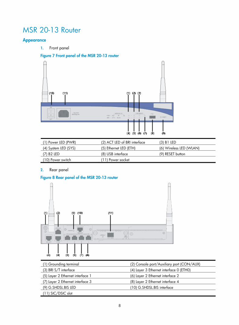
Figure 7 Front panel of the MSR 20-13 router
(1) Power LED (PWR) (2) ACT LED of BRI interface (3) B1 LED (4) System LED (SYS) (5) Ethernet LED (ETH) (6) Wireless LED (WLAN) (7) B2 LED (8) USB interface (9) RESET button (10) Power switch (11) Power socket
2. Rear panel
Figure 8 Rear panel of the MSR 20-13 router
(1) Grounding terminal (2) Console port/Auxiliary port (CON/AUX) (3) BRI S/T interface (4) Layer 3 Ethernet interface 0 (ETH0) (5) Layer 2 Ethernet interface 1 (6) Layer 2 Ethernet interface 2 (7) Layer 2 Ethernet interface 3 (8) Layer 2 Ethernet interface 4 (9) G.SHDSL.BIS LED (10) G.SHDSL.BIS interface (11) SIC/DSIC slot
9
Panel LEDs
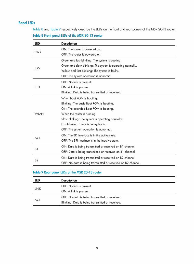
Table 8 and Table 9 respectively describe the LEDs on the front and rear panels of the MSR 20-13 router.
Table 8 Front panel LEDs of the MSR 20-13 router
LED Description
PWR ON: The router is powered on.
OFF: The router is powered off.
SYS
Green and fast blinking: The system is booting.
Green and slow blinking: The system is operating normally.
Yellow and fast blinking: The system is faulty.
OFF: The system operation is abnormal.
ETH
OFF: No link is present.
ON: A link is present.
Blinking: Data is being transmitted or received.
WLAN
When Boot ROM is booting:
Blinking: The basic Boot ROM is booting.
ON: The extended Boot ROM is booting.
When the router is running:
Slow blinking: The system is operating normally.
Fast blinking: There is heavy traffic.
OFF: The system operation is abnormal.
ACT ON: The BRI interface is in the active state.
OFF: The BRI interface is in the inactive state.
B1 ON: Data is being transmitted or received on B1 channel.
OFF: Data is being transmitted or received on B1 channel.
B2 ON: Data is being transmitted or received on B2 channel.
OFF: No data is being transmitted or received on B2 channel.
Table 9 Rear panel LEDs of the MSR 20-13 router
LED Description
LINK OFF: No link is present.
ON: A link is present.
ACT OFF: No data is being transmitted or received.
Blinking: Data is being transmitted or received.
10
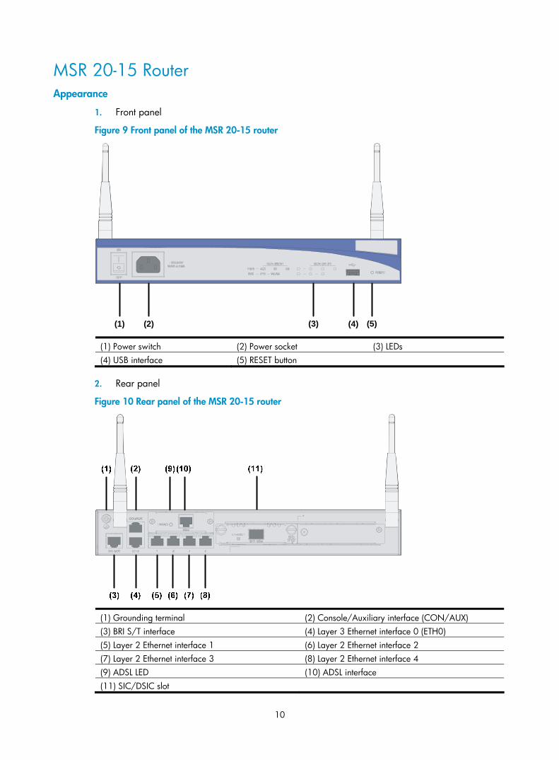
MSR 20-15 Router Appearance
1. Front panel
Figure 9 Front panel of the MSR 20-15 router
(1) (2) (3) (4) (5)
(1) Power switch (2) Power socket (3) LEDs (4) USB interface (5) RESET button
2. Rear panel
Figure 10 Rear panel of the MSR 20-15 router
(1) Grounding terminal (2) Console/Auxiliary interface (CON/AUX) (3) BRI S/T interface (4) Layer 3 Ethernet interface 0 (ETH0) (5) Layer 2 Ethernet interface 1 (6) Layer 2 Ethernet interface 2 (7) Layer 2 Ethernet interface 3 (8) Layer 2 Ethernet interface 4 (9) ADSL LED (10) ADSL interface (11) SIC/DSIC slot
11
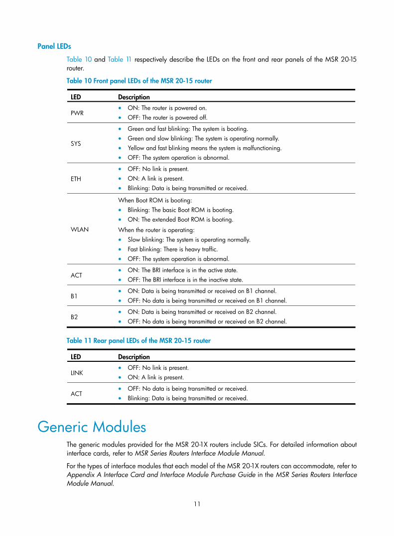
Panel LEDs
Table 10 and Table 11 respectively describe the LEDs on the front and rear panels of the MSR 20-15 router.
Table 10 Front panel LEDs of the MSR 20-15 router
LED Description
PWR • ON: The router is powered on. • OFF: The router is powered off.
SYS
• Green and fast blinking: The system is booting. • Green and slow blinking: The system is operating normally. • Yellow and fast blinking means the system is malfunctioning. • OFF: The system operation is abnormal.
ETH
• OFF: No link is present. • ON: A link is present. • Blinking: Data is being transmitted or received.
WLAN
When Boot ROM is booting: • Blinking: The basic Boot ROM is booting. • ON: The extended Boot ROM is booting.
When the router is operating: • Slow blinking: The system is operating normally. • Fast blinking: There is heavy traffic. • OFF: The system operation is abnormal.
ACT • ON: The BRI interface is in the active state. • OFF: The BRI interface is in the inactive state.
B1 • ON: Data is being transmitted or received on B1 channel. • OFF: No data is being transmitted or received on B1 channel.
B2 • ON: Data is being transmitted or received on B2 channel. • OFF: No data is being transmitted or received on B2 channel.
Table 11 Rear panel LEDs of the MSR 20-15 router
LED Description
LINK • OFF: No link is present. • ON: A link is present.
ACT • OFF: No data is being transmitted or received. • Blinking: Data is being transmitted or received.
Generic Modules The generic modules provided for the MSR 20-1X routers include SICs. For detailed information about interface cards, refer to MSR Series Routers Interface Module Manual.
For the types of interface modules that each model of the MSR 20-1X routers can accommodate, refer to Appendix A Interface Card and Interface Module Purchase Guide in the MSR Series Routers Interface Module Manual.
12
SICs and DSICs MSR 20-1X routers adopt modular design and provide the following interfaces to support a wide range of optional SICs/DSICs:
• Synchronous/asynchronous serial interface
• Ethernet port
• E1/T1 interface
• ISDN BRI/PRI
• ADSL interface
• Voice interface
• Layer 2 Ethernet interface
13
Installation Preparations
Requirements on Environment MSR 20-1X routers are designed for indoor application. To ensure the normal operation and prolong their service life, the installation site must meet the requirements mentioned in the following sections.
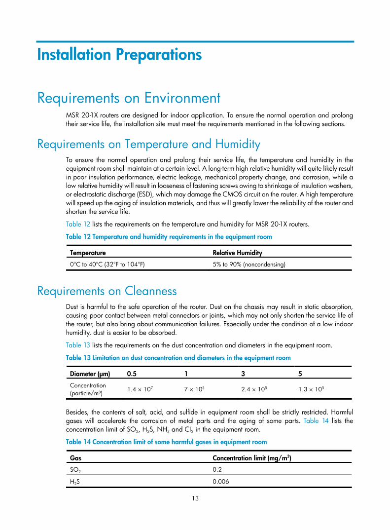
Requirements on Temperature and Humidity To ensure the normal operation and prolong their service life, the temperature and humidity in the equipment room shall maintain at a certain level. A long-term high relative humidity will quite likely result in poor insulation performance, electric leakage, mechanical property change, and corrosion, while a low relative humidity will result in looseness of fastening screws owing to shrinkage of insulation washers, or electrostatic discharge (ESD), which may damage the CMOS circuit on the router. A high temperature will speed up the aging of insulation materials, and thus will greatly lower the reliability of the router and shorten the service life.
Table 12 lists the requirements on the temperature and humidity for MSR 20-1X routers.
Table 12 Temperature and humidity requirements in the equipment room
Temperature Relative Humidity
0°C to 40°C (32°F to 104°F) 5% to 90% (noncondensing)
Requirements on Cleanness Dust is harmful to the safe operation of the router. Dust on the chassis may result in static absorption, causing poor contact between metal connectors or joints, which may not only shorten the service life of the router, but also bring about communication failures. Especially under the condition of a low indoor humidity, dust is easier to be absorbed.
Table 13 lists the requirements on the dust concentration and diameters in the equipment room.
Table 13 Limitation on dust concentration and diameters in the equipment room
Diameter (μm) 0.5 1 3 5
Concentration (particle/m³) 1.4 × 10⁷ 7 × 10⁵ 2.4 × 10⁵ 1.3 × 10⁵
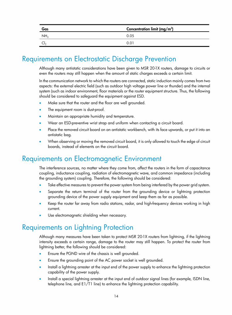
Besides, the contents of salt, acid, and sulfide in equipment room shall be strictly restricted. Harmful gases will accelerate the corrosion of metal parts and the aging of some parts. Table 14 lists the concentration limit of SO2, H2S, NH3 and CI2 in the equipment room.
Table 14 Concentration limit of some harmful gases in equipment room
Gas Concentration limit (mg/m3)
SO2 0.2
H2S 0.006
14
Gas Concentration limit (mg/m3)
NH3 0.05
Cl2 0.01
Requirements on Electrostatic Discharge Prevention Although many antistatic considerations have been given to MSR 20-1X routers, damage to circuits or even the routers may still happen when the amount of static charges exceeds a certain limit.
In the communication network to which the routers are connected, static induction mainly comes from two aspects: the external electric field (such as outdoor high voltage power line or thunder) and the internal system (such as indoor environment, floor materials or the router equipment structure. Thus, the following should be considered to safeguard the equipment against ESD.
• Make sure that the router and the floor are well grounded.
• The equipment room is dust-proof.
• Maintain an appropriate humidity and temperature.
• Wear an ESD-preventive wrist strap and uniform when contacting a circuit board.
• Place the removed circuit board on an antistatic workbench, with its face upwards, or put it into an antistatic bag.
• When observing or moving the removed circuit board, it is only allowed to touch the edge of circuit boards, instead of elements on the circuit board.
Requirements on Electromagnetic Environment The interference sources, no matter where they come from, affect the routers in the form of capacitance coupling, inductance coupling, radiation of electromagnetic wave, and common impedance (including the grounding system) coupling. Therefore, the following should be considered:
• Take effective measures to prevent the power system from being interfered by the power grid system.
• Separate the return terminal of the router from the grounding device or lightning protection grounding device of the power supply equipment and keep them as far as possible.
• Keep the router far away from radio stations, radar, and high-frequency devices working in high current.
• Use electromagnetic shielding when necessary.
Requirements on Lightning Protection Although many measures have been taken to protect MSR 20-1X routers from lightning, if the lightning intensity exceeds a certain range, damage to the router may still happen. To protect the router from lightning better, the following should be considered:
• Ensure the PGND wire of the chassis is well grounded.
• Ensure the grounding point of the AC power socket is well grounded.
• Install a lightning arrester at the input end of the power supply to enhance the lightning protection capability of the power supply.
• Install a special lightning arrester at the input end of outdoor signal lines (for example, ISDN line, telephone line, and E1/T1 line) to enhance the lightning protection capability.
15
Checking the Rack When installing MSR 20-1X routers, make sure that:
• There is spacing reserved at the air inlet and exhaust in the router for the purpose of heat dissipation of the router chassis.
• The rack has a good ventilation system for heat dissipation.
• The rack is solid enough to support the weight of the device and the installation accessories.
• The rack is well-grounded.
Safety Precautions Routers play an important role in data communications network. Please pay attention to the following signs:
WARNING: Means the reader be extremely careful. Improper operation may cause bodily injury.
CAUTION: Means the reader be careful. Improper operation may cause data loss or damage to equipment.
When installing or working on the router, observe the following recommendations:
• Keep the router far away from heat sources and dampness.
• Ground the router correctly.
• Wear an ESD-preventive wrist strap, making sure that the strap has good skin contact.
• Do not insert or remove interface modules or interface cards of the router when the power supply is connected.
• Do not insert or remove a cable when the power supply is connected.
• Connect the interface cables correctly for the router. Do not connect a telephone line (including ISDN line) to a serial port.
• Use laser with caution. Do not directly stare into apertures or fiber-optic connectors that emit laser radiation.
• Equip an uninterrupted power supply (UPS).
Installation Tools, Meters and Equipment Tools
• Phillips screwdriver
• Straight screwdriver
• ESD-preventive twist strap
Cables
• PGND cable and power cord
• Console cable
• Optional cables

16
Meters and equipment
• Hub or LAN switch
• Console terminal (for example, a PC)
• Equipment related to the selected modules
• Multimeter
CAUTION:
None of the above-mentioned installation tools, meters, and equipment is shipped with MSR 20-1X routers
17
Installation
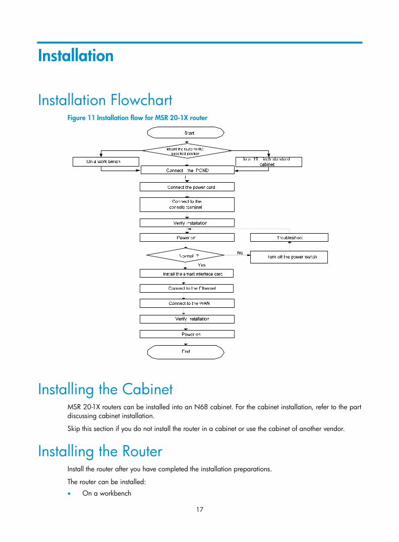
Installation Flowchart Figure 11 Installation flow for MSR 20-1X router
Installing the Cabinet MSR 20-1X routers can be installed into an N68 cabinet. For the cabinet installation, refer to the part discussing cabinet installation.
Skip this section if you do not install the router in a cabinet or use the cabinet of another vendor.
Installing the Router Install the router after you have completed the installation preparations.
The router can be installed:
• On a workbench
18
• In a cabinet
• On a wall
Installing the Router on a Workbench In case that no 19-inch standard cabinet is available, you can put the router on a clean workbench. When installing the router on a workbench,
• Make sure that the workbench is stable and well grounded.
• Reserve a space of 10 cm (3.9 in.) around the router for heat dissipation.
• Do not place heavy objects on the router.
Installing the Router on a Cabinet Dimensions
With mounting brackets, you can also install MSR 20-1X routers in a 19-inch standard cabinet.
The dimensions of MSR 20-1X routers without feet and mounting bracket are 44.2 × 300 × 240 mm (1.74 × 11.81 × 9.45 in.).
Installation procedure
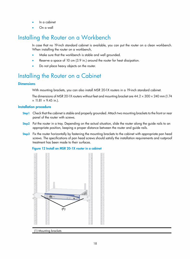
Step1 Check that the cabinet is stable and properly grounded. Attach two mounting brackets to the front or rear panel of the router with screws.
Step2 Put the router in a tray. Depending on the actual situation, slide the router along the guide rails to an appropriate position, keeping a proper distance between the router and guide rails.
Step3 Fix the router horizontally by fastening the mounting brackets to the cabinet with appropriate pan head screws. The specifications of pan head screws should satisfy the installation requirements and rustproof treatment has been made to their surfaces.
Figure 12 Install an MSR 20-1X router in a cabinet
(1) Mounting brackets
19
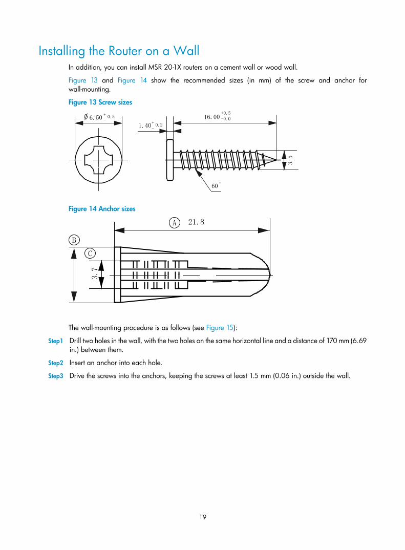
Installing the Router on a Wall In addition, you can install MSR 20-1X routers on a cement wall or wood wall.
Figure 13 and Figure 14 show the recommended sizes (in mm) of the screw and anchor for wall-mounting.
Figure 13 Screw sizes
16.00+0.5-0.0
1.406.50
+-
+-
0.2
0.5
60。
3.5
Figure 14 Anchor sizes
A
B
3.7
C
21.8
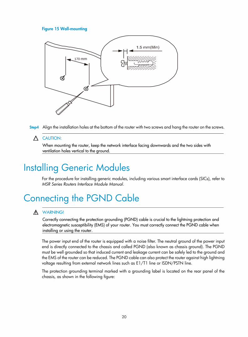
The wall-mounting procedure is as follows (see Figure 15):
Step1 Drill two holes in the wall, with the two holes on the same horizontal line and a distance of 170 mm (6.69 in.) between them.
Step2 Insert an anchor into each hole.
Step3 Drive the screws into the anchors, keeping the screws at least 1.5 mm (0.06 in.) outside the wall.
20
Figure 15 Wall-mounting
170 mm
Step4 Align the installation holes at the bottom of the router with two screws and hang the router on the screws.
CAUTION:
When mounting the router, keep the network interface facing downwards and the two sides with ventilation holes vertical to the ground.
Installing Generic Modules For the procedure for installing generic modules, including various smart interface cards (SICs), refer to MSR Series Routers Interface Module Manual.
Connecting the PGND Cable
WARNING!
Correctly connecting the protection grounding (PGND) cable is crucial to the lightning protection and electromagnetic susceptibility (EMS) of your router. You must correctly connect the PGND cable when installing or using the router.
The power input end of the router is equipped with a noise filter. The neutral ground of the power input end is directly connected to the chassis and called PGND (also known as chassis ground). The PGND must be well grounded so that induced current and leakage current can be safely led to the ground and the EMS of the router can be reduced. The PGND cable can also protect the router against high lightning voltage resulting from external network lines such as E1/T1 line or ISDN/PSTN line.
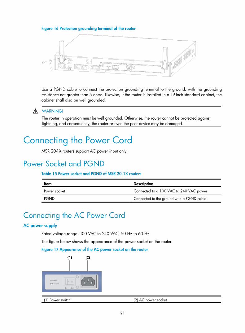
The protection grounding terminal marked with a grounding label is located on the rear panel of the chassis, as shown in the following figure:
21
Figure 16 Protection grounding terminal of the router
Use a PGND cable to connect the protection grounding terminal to the ground, with the grounding resistance not greater than 5 ohms. Likewise, if the router is installed in a 19-inch standard cabinet, the cabinet shall also be well grounded.
WARNING!
The router in operation must be well grounded. Otherwise, the router cannot be protected against lightning, and consequently, the router or even the peer device may be damaged.
Connecting the Power Cord MSR 20-1X routers support AC power input only.
Power Socket and PGND Table 15 Power socket and PGND of MSR 20-1X routers
Item Description
Power socket Connected to a 100 VAC to 240 VAC power
PGND Connected to the ground with a PGND cable
Connecting the AC Power Cord AC power supply
Rated voltage range: 100 VAC to 240 VAC, 50 Hz to 60 Hz
The figure below shows the appearance of the power socket on the router:
Figure 17 Appearance of the AC power socket on the router
(1) Power switch (2) AC power socket
22
Recommended AC power connector
A three-terminal, single-phase power connector with a grounding contact is recommended. Normally, the grounding contact of the power supply system in a building was buried during construction and cabling. Before connecting the AC power cord, you must make sure that the power supply of the building has been well grounded.
Connecting the AC power cord
Step1 Make sure that the PGND is securely connected to the ground.
Step2 Move the power switch of the router to the OFF position, and connect one end of the power cord shipped with the router to the power socket on the rear panel, and the other end to an AC power source.
Step3 Move the power switch to the ON position.
Step4 Check whether the power LED on the front panel of the router is ON. If the power LED is ON, the power cord is properly connected.
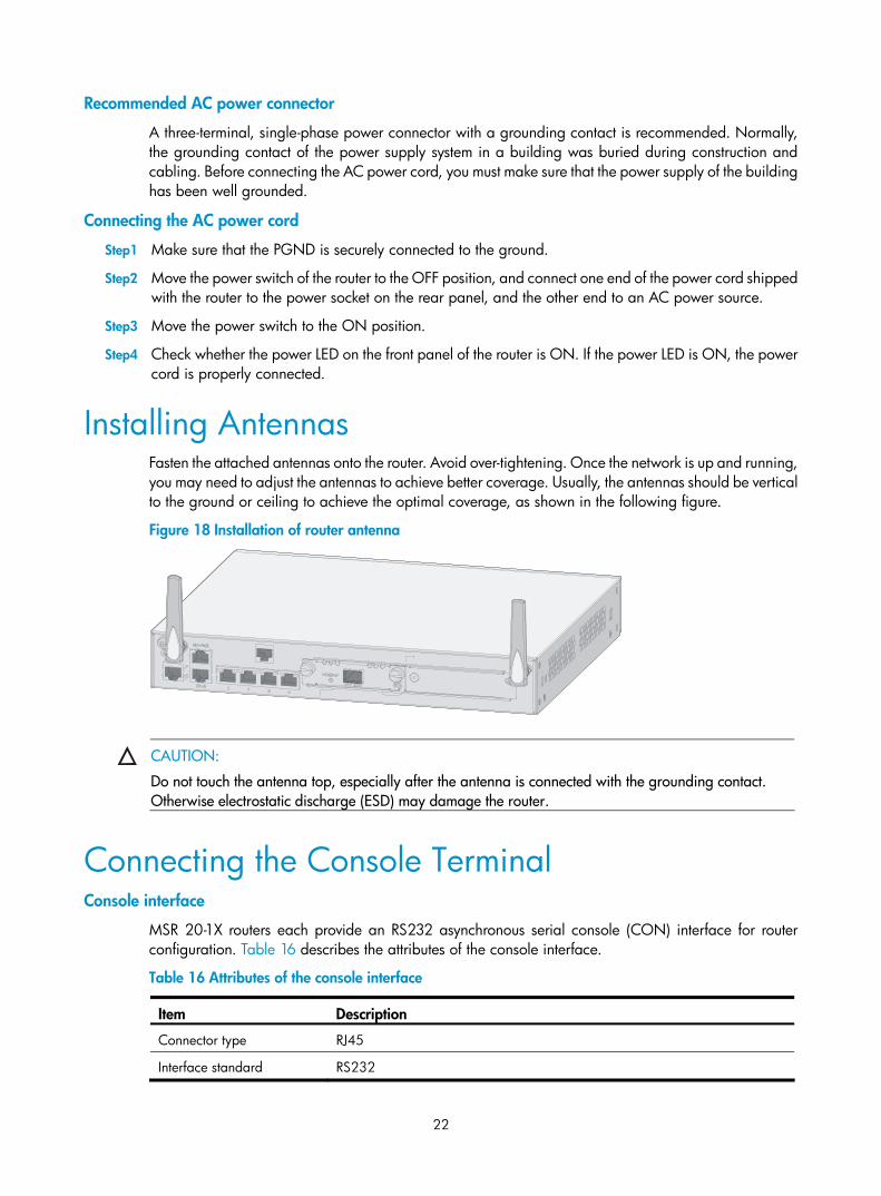
Installing Antennas Fasten the attached antennas onto the router. Avoid over-tightening. Once the network is up and running, you may need to adjust the antennas to achieve better coverage. Usually, the antennas should be vertical to the ground or ceiling to achieve the optimal coverage, as shown in the following figure.
Figure 18 Installation of router antenna
CAUTION:
Do not touch the antenna top, especially after the antenna is connected with the grounding contact. Otherwise electrostatic discharge (ESD) may damage the router.
Connecting the Console Terminal Console interface
MSR 20-1X routers each provide an RS232 asynchronous serial console (CON) interface for router configuration. Table 16 describes the attributes of the console interface.
Table 16 Attributes of the console interface
Item Description
Connector type RJ45
Interface standard RS232
23
Item Description
Baud rate 9600 bps (default) to 115200 bps
Supported services • Connected with a character terminal • Connecting to the serial interface of the local PC and running terminal
emulation program on the PC Command line interface
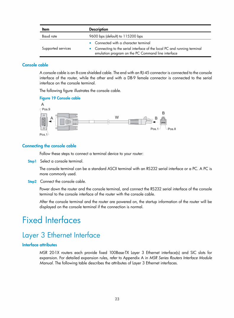
Console cable
A console cable is an 8-core shielded cable. The end with an RJ-45 connector is connected to the console interface of the router, while the other end with a DB-9 female connector is connected to the serial interface on the console terminal.
The following figure illustrates the console cable.
Figure 19 Console cable
Connecting the console cable
Follow these steps to connect a terminal device to your router:
Step1 Select a console terminal.
The console terminal can be a standard ASCII terminal with an RS232 serial interface or a PC. A PC is more commonly used.
Step2 Connect the console cable.
Power down the router and the console terminal, and connect the RS232 serial interface of the console terminal to the console interface of the router with the console cable.
After the console terminal and the router are powered on, the startup information of the router will be displayed on the console terminal if the connection is normal.
Fixed Interfaces
Layer 3 Ethernet Interface Interface attributes
MSR 20-1X routers each provide fixed 100Base-TX Layer 3 Ethernet interface(s) and SIC slots for expansion. For detailed expansion rules, refer to Appendix A in MSR Series Routers Interface Module Manual. The following table describes the attributes of Layer 3 Ethernet interfaces.
24
Table 17 Attributes of Layer 3 Ethernet interfaces
Item Description
Connector type RJ45
Interface type MDI/MDI-X autosensing
Frame format Ethernet_II
Ethernet_SNAP
Operating mode 10/100 Mbps autosensing
Half duplex/full duplex
NOTE:
Media dependent interface (MDI) is a typical Ethernet interface provided by network adapters, while media-dependent interface crossover (MDIX) is an interface commonly found on a hub or LAN switch.
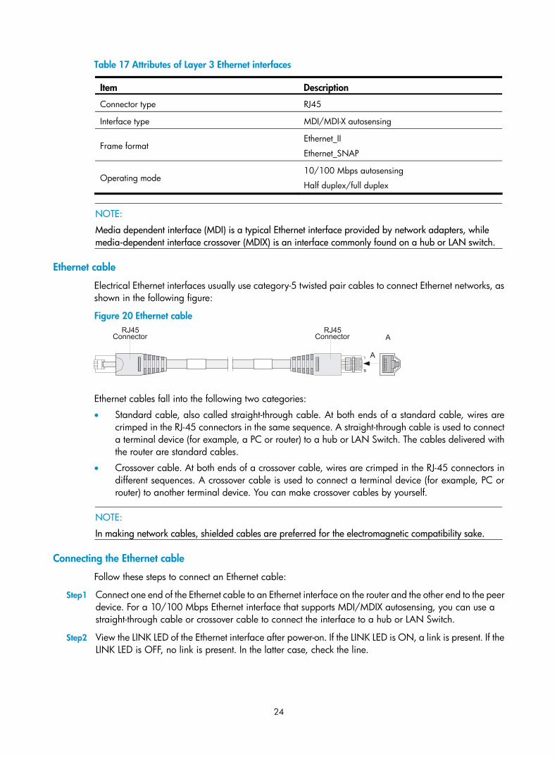
Ethernet cable
Electrical Ethernet interfaces usually use category-5 twisted pair cables to connect Ethernet networks, as shown in the following figure:
Figure 20 Ethernet cable
Ethernet cables fall into the following two categories:
• Standard cable, also called straight-through cable. At both ends of a standard cable, wires are crimped in the RJ-45 connectors in the same sequence. A straight-through cable is used to connect a terminal device (for example, a PC or router) to a hub or LAN Switch. The cables delivered with the router are standard cables.
• Crossover cable. At both ends of a crossover cable, wires are crimped in the RJ-45 connectors in different sequences. A crossover cable is used to connect a terminal device (for example, PC or router) to another terminal device. You can make crossover cables by yourself.
NOTE:
In making network cables, shielded cables are preferred for the electromagnetic compatibility sake.
Connecting the Ethernet cable
Follow these steps to connect an Ethernet cable:
Step1 Connect one end of the Ethernet cable to an Ethernet interface on the router and the other end to the peer device. For a 10/100 Mbps Ethernet interface that supports MDI/MDIX autosensing, you can use a straight-through cable or crossover cable to connect the interface to a hub or LAN Switch.
Step2 View the LINK LED of the Ethernet interface after power-on. If the LINK LED is ON, a link is present. If the LINK LED is OFF, no link is present. In the latter case, check the line.
25
Layer 2 Ethernet interface attributes
MSR 20-1X routers each provide fixed 100Base-TX Layer 2 Ethernet interfaces. The following table describes the attributes of Layer 2 Ethernet interfaces.
Table 18 Attributes of Layer 2 Ethernet interfaces
Item Description
Connector RJ45
Interface type MDI/MDIX
Frame format Ethernet_II
Ethernet_SNAP
Operating mode 10/100 Mbps autosensing
Half duplex/full duplex
NOTE:
Media dependent interface (MDI) is a typical Ethernet interface provided by network adapters, while media-dependent interface crossover (MDIX) is an interface commonly found on a hub or LAN switch.
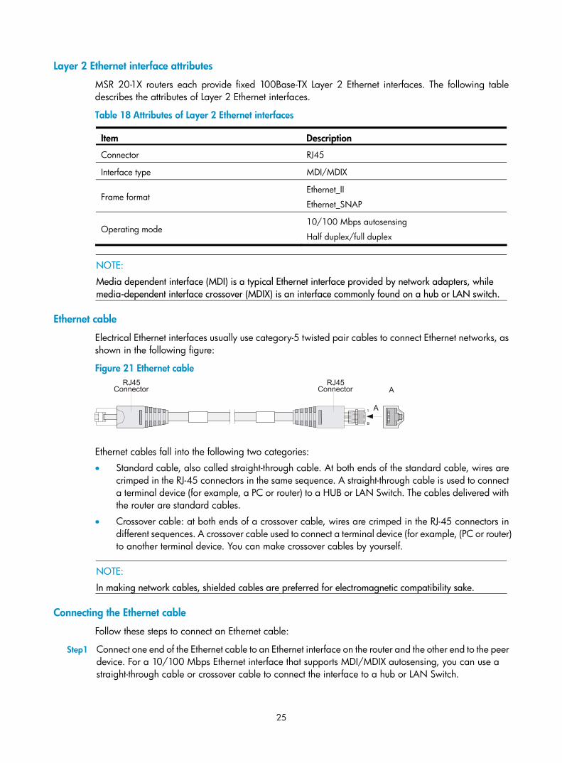
Ethernet cable
Electrical Ethernet interfaces usually use category-5 twisted pair cables to connect Ethernet networks, as shown in the following figure:
Figure 21 Ethernet cable
Ethernet cables fall into the following two categories:
• Standard cable, also called straight-through cable. At both ends of the standard cable, wires are crimped in the RJ-45 connectors in the same sequence. A straight-through cable is used to connect a terminal device (for example, a PC or router) to a HUB or LAN Switch. The cables delivered with the router are standard cables.
• Crossover cable: at both ends of a crossover cable, wires are crimped in the RJ-45 connectors in different sequences. A crossover cable used to connect a terminal device (for example, (PC or router) to another terminal device. You can make crossover cables by yourself.
NOTE:
In making network cables, shielded cables are preferred for electromagnetic compatibility sake.
Connecting the Ethernet cable
Follow these steps to connect an Ethernet cable:
Step1 Connect one end of the Ethernet cable to an Ethernet interface on the router and the other end to the peer device. For a 10/100 Mbps Ethernet interface that supports MDI/MDIX autosensing, you can use a straight-through cable or crossover cable to connect the interface to a hub or LAN Switch.
26
Step2 View the LINK LED of the Ethernet interface. If the LINK LED is ON, a link is present. If the LINK LED is OFF, no link is present. In the latter case, check the line.
Connecting the AUX Interface to a Modem AUX interface
The AUX interface is an RS232 asynchronous serial interface, which can serve as a backup interface of a WAN interface and provide dial connection. In case of console failure, the AUX interface can function as the console interface.
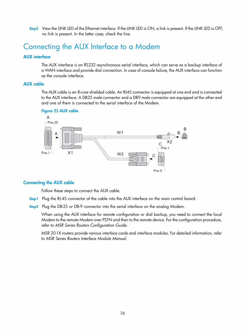
AUX cable
The AUX cable is an 8-core shielded cable. An RJ45 connector is equipped at one end and is connected to the AUX interface. A DB25 male connector and a DB9 male connector are equipped at the other end and one of them is connected to the serial interface of the Modem.
Figure 22 AUX cable
Connecting the AUX cable
Follow these steps to connect the AUX cable.
Step1 Plug the RJ-45 connector of the cable into the AUX interface on the main control board.
Step2 Plug the DB-25 or DB-9 connector into the serial interface on the analog Modem.
When using the AUX interface for remote configuration or dial backup, you need to connect the local Modem to the remote Modem over PSTN and then to the remote device. For the configuration procedure, refer to MSR Series Routers Configuration Guide.
MSR 20-1X routers provide various interface cards and interface modules. For detailed information, refer to MSR Series Routers Interface Module Manual.
27
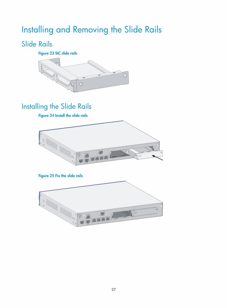
Installing and Removing the Slide Rails
Slide Rails Figure 23 SIC slide rails
Installing the Slide Rails Figure 24 Install the slide rails
Figure 25 Fix the slide rails
28
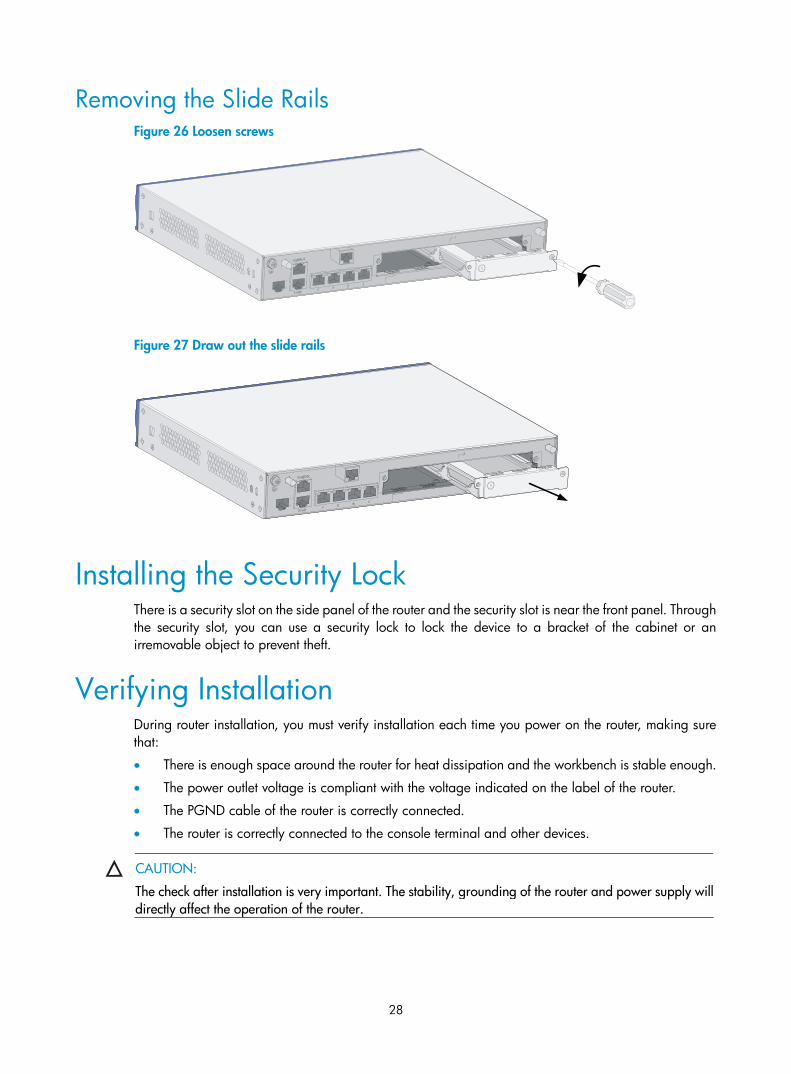
Removing the Slide Rails Figure 26 Loosen screws
Figure 27 Draw out the slide rails
Installing the Security Lock There is a security slot on the side panel of the router and the security slot is near the front panel. Through the security slot, you can use a security lock to lock the device to a bracket of the cabinet or an irremovable object to prevent theft.
Verifying Installation During router installation, you must verify installation each time you power on the router, making sure that:
• There is enough space around the router for heat dissipation and the workbench is stable enough.
• The power outlet voltage is compliant with the voltage indicated on the label of the router.
• The PGND cable of the router is correctly connected.
• The router is correctly connected to the console terminal and other devices.
CAUTION:
The check after installation is very important. The stability, grounding of the router and power supply willdirectly affect the operation of the router.
29
Startup and Configuration
Startup Configure MSR 20-1X routers only through the console interface for the first time.
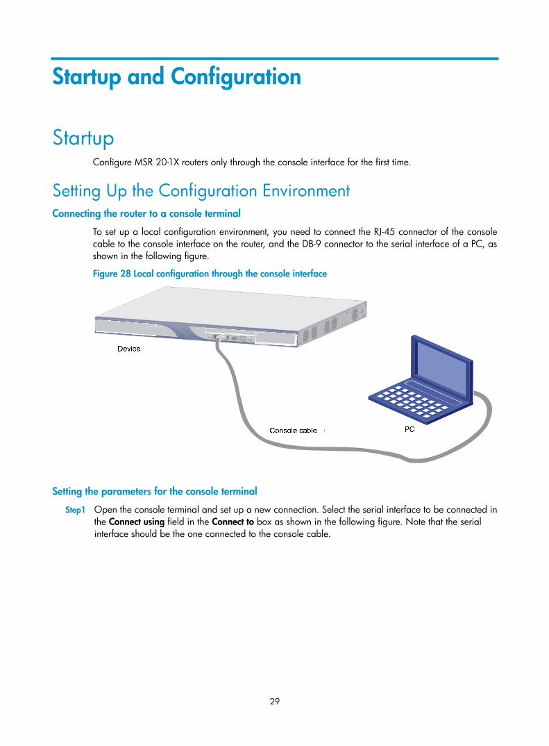
Setting Up the Configuration Environment Connecting the router to a console terminal
To set up a local configuration environment, you need to connect the RJ-45 connector of the console cable to the console interface on the router, and the DB-9 connector to the serial interface of a PC, as shown in the following figure.
Figure 28 Local configuration through the console interface
Devece
PCConsole cable
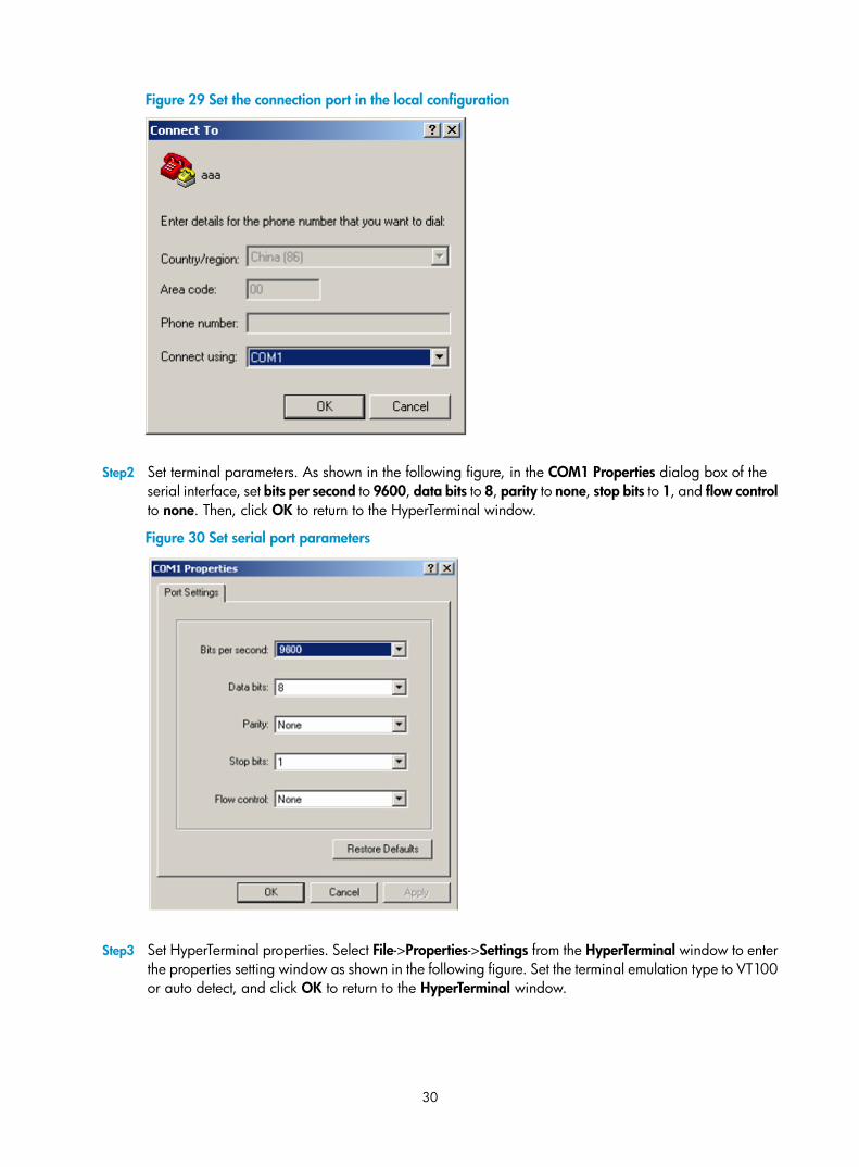
Setting the parameters for the console terminal
Step1 Open the console terminal and set up a new connection. Select the serial interface to be connected in the Connect using field in the Connect to box as shown in the following figure. Note that the serial interface should be the one connected to the console cable.
30
Figure 29 Set the connection port in the local configuration
Step2 Set terminal parameters. As shown in the following figure, in the COM1 Properties dialog box of the serial interface, set bits per second to 9600, data bits to 8, parity to none, stop bits to 1, and flow control to none. Then, click OK to return to the HyperTerminal window.
Figure 30 Set serial port parameters
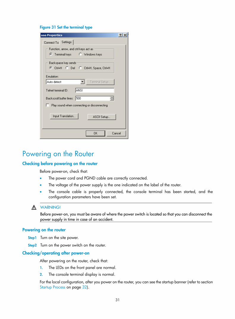
Step3 Set HyperTerminal properties. Select File->Properties->Settings from the HyperTerminal window to enter the properties setting window as shown in the following figure. Set the terminal emulation type to VT100 or auto detect, and click OK to return to the HyperTerminal window.
31
Figure 31 Set the terminal type
Powering on the Router Checking before powering on the router
Before power-on, check that:
• The power cord and PGND cable are correctly connected.
• The voltage of the power supply is the one indicated on the label of the router.
• The console cable is properly connected, the console terminal has been started, and the configuration parameters have been set.
WARNING!
Before power-on, you must be aware of where the power switch is located so that you can disconnect thepower supply in time in case of an accident.
Powering on the router
Step1 Turn on the site power.
Step2 Turn on the power switch on the router.
Checking/operating after power-on
After powering on the router, check that:
1. The LEDs on the front panel are normal.
2. The console terminal display is normal.
For the local configuration, after you power on the router, you can see the startup banner (refer to section Startup Process on page 32).
32
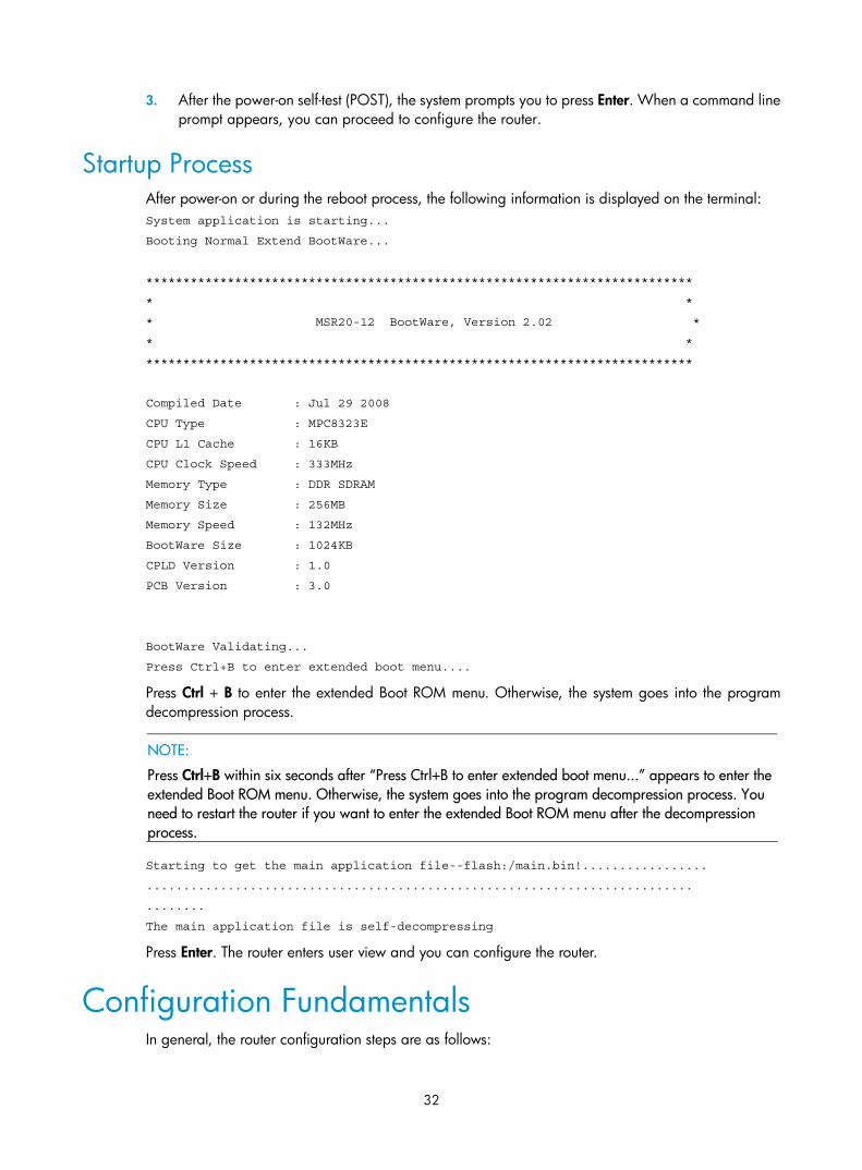
3. After the power-on self-test (POST), the system prompts you to press Enter. When a command line prompt appears, you can proceed to configure the router.
Startup Process After power-on or during the reboot process, the following information is displayed on the terminal: System application is starting...
Booting Normal Extend BootWare...
**************************************************************************
* *
* MSR20-12 BootWare, Version 2.02 *
* *
**************************************************************************
Compiled Date : Jul 29 2008
CPU Type : MPC8323E
CPU L1 Cache : 16KB
CPU Clock Speed : 333MHz
Memory Type : DDR SDRAM
Memory Size : 256MB
Memory Speed : 132MHz
BootWare Size : 1024KB
CPLD Version : 1.0
PCB Version : 3.0
BootWare Validating...
Press Ctrl+B to enter extended boot menu....
Press Ctrl + B to enter the extended Boot ROM menu. Otherwise, the system goes into the program decompression process.
NOTE:
Press Ctrl+B within six seconds after “Press Ctrl+B to enter extended boot menu...” appears to enter the extended Boot ROM menu. Otherwise, the system goes into the program decompression process. You need to restart the router if you want to enter the extended Boot ROM menu after the decompression process.
Starting to get the main application file--flash:/main.bin!.................
..........................................................................
........
The main application file is self-decompressing
Press Enter. The router enters user view and you can configure the router.
Configuration Fundamentals In general, the router configuration steps are as follows:
33
Step1 Before configuration, you should make specific network requirements, including the objective, role of the router in the network, division of subnets, WAN type and transmission medium, network security policy and reliability.
Step2 Based on the above requirements, draw a clear, complete network diagram.
Step3 Configure the WAN interface of the router. First, configure the operating parameters (for example, the operating mode of the serial interface, baud rate and synchronous clock) of the interface according to the transmission medium of the WAN. For a dialer interface, you also need to configure DCC parameters. Then, configure the link layer protocol encapsulated on the interface and corresponding operating parameters.
Step4 Configure the IP addresses or IPX network numbers of all the interfaces on the router according to the division of the subnets.
Step5 Configure the routes. If it is necessary to enable a dynamic routing protocol, you should configure related operating parameters of the protocol.
Step6 If special security is required, perform the special security configuration for the router.
Step7 If special reliability is required, perform the special reliability configuration for the router.
For the configuration details of the protocols or functions of the router, refer to MSR Series Routers Configuration Guide.
Command Line Interface Functions of the command line interface
The command line interface (CLI) of MSR 20-1X routers provide a number of configuration commands, which can be used to configure and manage the router. The CLI provides the following functions:
• Allows you to perform the local configuration through the console interface.
• Allows you to perform the local or remote configuration and directly log in to other routers for the management purpose by using the telnet command.
• Provides online help after you enter “?”.
• Provides network diagnostic tools, such as Tracert and Ping, to quickly diagnose the availability of the network.
• Provides all kinds of detailed debugging information to help diagnose network faults.
• Provides a command line interpreter, which adopts fuzzy search for the keywords of the command. If you enter a conflict-free keyword for a command, the command will be interpreted accordingly. For example, for a display command, you can just enter dis and the command will be interpreted.
Command line interface view
The command line interface of MSR 20-1X routers provide plenty of configuration commands. All the commands are grouped in system view. Each group corresponds to a view. You can use commands to switch between different configuration views. In general, only certain commands can be executed in a particular view. But some common commands (such as ping and display current-configuration) can be executed in any view.
34
Slot Arrangement and Rules for Numbering Interfaces Slot arrangement
The MSR 20-1X routers provide many types of interfaces, such as console, AUX, Ethernet, serial interface (synchronous/asynchronous), and asynchronous interface. The following describes how these interfaces are numbered.
Rules for numbering interfaces
The interfaces of the MSR 20-1X routers are numbered with “two dimensions”:
• The interfaces are represented by interface-type X/Y, where interface-type can be serial, asynchronous, or Ethernet, X specifies the slot number and Y specifies the interface number.
• Fixed interfaces are on Slot 0 and the expansion slot is defined as Slot 1.
• Different interfaces on an interface module share the same slot number X.
• For each interface, Y starts from 0 indicates the interface sequence on the interface module, from left to right.
If you install an SIC-4FSW in slot 1 on the MSR 20-11, the Ethernet interfaces are numbered as follows:
• Layer 3 Ethernet interface is numbered Ethernet 0/0;
• The Layer 3 Ethernet interfaces on the SIC-4FSW module are numbered Ethernet 1/0, Ethernet 1/1, Ethernet 1/2, and Ethernet 1/3.
35
Software Maintenance
Introduction
Files Managed by the Router BootWare file
The BootWare file is used to boot an application. A complete BootWare file includes two segments: basic and extended.
Application files
By default, the MSR 20-1X routers define three application files for booting: main, backup, and secure. The system selects these three files in sequence to start up the router. Currently only one application file is stored in the Flash memory of the MSR 20-1X routers due to limited memory size. To change the file selection sequence or modify an application file, refer to Maintaining Application and Configuration Files on page 55 for details.
The details about the three application files are as follows:
• Main file: The file used for booting by default. The default file name is main.bin and the file type is M.
• Backup file: The default file name is backup.bin and the file type is B. The system uses the backup file when it fails to boot using the main file.
• Secure file: The default file name is secure.bin and the file type is S. The system uses the secure file when it fails to boot using the backup boot file. If the system fails to boot using the secure boot file, it prompts a boot failure.
NOTE:
• The application files for system boot can be type M, B, and S, but not type N (namely, types other thantype M, B, or S).
• You can modify the name of an application file in storage after the application file is loaded. You cannotmodify the type of a type S application file, but you can modify the type of a type M, B, or N applicationfile using the BootWare menu or using commands after the application file is loaded.
• The secure file is the last resort for system boot. You can download it in the BootWare menu and must name it secure.bin. However, you cannot modify the type of this file or change the type of other files toS. If you change the name of the secure file with the rename command after system boot, the file is removed from the Flash memory and you need to download it again.
• You can store type M, B, S files in storage devices, but only one for each type in each storage device. Forexample, if a type M+B file exists in the Flash memory, there will be no type M or B file. If you changethe type of a file to B, the M+B file will become a type M file.
Configuration files
The configuration files store configuration information of the router.
36
By default, the system defines three configuration files for booting: main, backup, and default file. If the three configuration files are loaded in a storage device, the system selects them in sequence until the router is successfully loaded. To change the sequence of these configuration files or modify them, refer to Maintaining Application and Configuration Files on page 55.
The details about the three configuration files are as follows:
• Main configuration file: The configuration file used for booting by default. The file type is M.
• Backup configuration file: The file type is B. The system uses the backup configuration file when it fails to boot using the main configuration file.
• Default configuration file: The file type can be M, B, or N. The system uses the default configuration file when it fails to boot using the backup configuration file. If the system fails to boot using the default configuration file, it boots with null configuration. The name of the default configuration file varies with router brands. The main and backup configuration operations on the default configuration file are the same as those on common configuration files.
NOTE:
• The configuration file for system boot can be a main configuration file, a backup configuration file, or default configuration file of type N, but not non-default configuration file of type N (namely, neither typeM nor type B).
• You can modify the file name of a configuration file in the Flash memory using a command after the configuration file is loaded. You cannot modify the type of the default configuration file, but you can modify the type of a type M, B, N configuration file in the BootWare menu, or using commands after theconfiguration file is loaded.
You can store type M and B configuration files in the flash memory, but only one for each. For example, if a type M+B configuration file exists, there will be no type M or B file. If you change the type of a configuration file to B, the M+B configuration file will become a type M file.
CAUTION:
• A file name can contain at most 64 characters (including drive letter and a string terminator). If the driveletters are “FLASH:/”, the file name can contain at most [64-1-7 ] = 56 characters; otherwise errors willoccur in file operation. Typically, a file name is recommended to be less than 16 characters.
• Extended ASCII characters (ASCII>=128) and invisible characters (ASCII<33) should not appear in a file name.
• The following characters should not appear in a file name: ”, ‘, ?, \, space, *, |, <, /, :, >, and ~.
• The dot “.” can appear in a file name, but not at the head or the end of the file name. Two consecutivedots are not allowed.
Software Maintenance Methods • Upgrade BootWare and an application using the XModem protocol through a serial port.
• Upgrade an application from a TFTP/FTP server through an Ethernet interface in BootWare.
• Upload/download an application and configuration file from a TFTP/FTP server via command lines.
37
NOTE:
• The BootWare program is upgraded together with the Blinux application program. You do not need toupgrade the BootWare separately. When upgrading the Blinux program, the system checks whether therunning BootWare version is consistent with that in the updating host application program. If inconsistent, the system asks whether to upgrade the BootWare. If you make no choice within one second, the system upgrades the BootWare automatically.
• When the flexible interface platform (FIP) starts, it automatically checks the running BootWare version.If the current version is inconsistent with the version used on the FIP, the system upgrades the BootWareautomatically.
• Check the current version of BootWare and application program before upgrade. For the version configuration information, see the corresponding Release Notes.
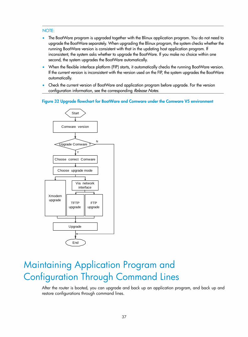
Figure 32 Upgrade flowchart for BootWare and Comware under the Comware V5 environment
Comware version
Start
End
Upgrade Comware ?
Choose upgrade mode
Xmodem upgrade
TFTP upgrade
FTP upgrade
Choose correct Comware
N
Y
Upgrade
Via network interface
Maintaining Application Program and Configuration Through Command Lines
After the router is booted, you can upgrade and back up an application program, and back up and restore configurations through command lines.
38
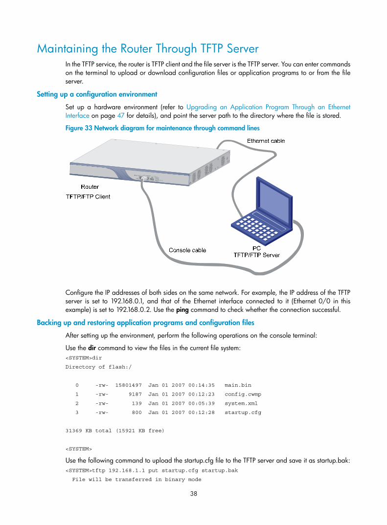
Maintaining the Router Through TFTP Server In the TFTP service, the router is TFTP client and the file server is the TFTP server. You can enter commands on the terminal to upload or download configuration files or application programs to or from the file server.
Setting up a configuration environment
Set up a hardware environment (refer to Upgrading an Application Program Through an Ethernet Interface on page 47 for details), and point the server path to the directory where the file is stored.
Figure 33 Network diagram for maintenance through command lines
Configure the IP addresses of both sides on the same network. For example, the IP address of the TFTP server is set to 192.168.0.1, and that of the Ethernet interface connected to it (Ethernet 0/0 in this example) is set to 192.168.0.2. Use the ping command to check whether the connection successful.
Backing up and restoring application programs and configuration files
After setting up the environment, perform the following operations on the console terminal:
Use the dir command to view the files in the current file system: <SYSTEM>dir
Directory of flash:/
0 -rw- 15801497 Jan 01 2007 00:14:35 main.bin
1 -rw- 9187 Jan 01 2007 00:12:23 config.cwmp
2 -rw- 139 Jan 01 2007 00:05:39 system.xml
3 -rw- 800 Jan 01 2007 00:12:28 startup.cfg
31369 KB total (15921 KB free)
<SYSTEM>
Use the following command to upload the startup.cfg file to the TFTP server and save it as startup.bak: <SYSTEM>tftp 192.168.1.1 put startup.cfg startup.bak
File will be transferred in binary mode
39
Sending file to remote tftp server. Please wait... \
TFTP: 1045 bytes sent in 0 second(s).
File uploaded successfully.
Use the following command to download the startup.cfg file from the server to the router: <SYSTEM>tftp 192.168.1.1 get startup.cfg startup.cfg
The file startup.cfg exists. Overwrite it?[Y/N]:y
Verifying server file...
Deleting the old file, please wait...
File will be transferred in binary mode
Downloading file from remote tftp server, please wait...\
TFTP: 1045 bytes received in 0 second(s)
File downloaded successfully.
If a startup.cfg file already exists in the router, the system prompts you whether to overwrite it. You can type Y or y to overwrite it.
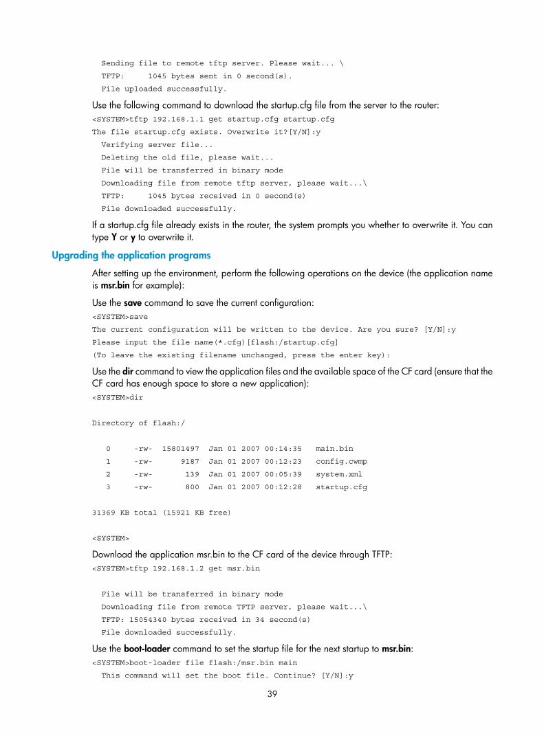
Upgrading the application programs
After setting up the environment, perform the following operations on the device (the application name is msr.bin for example):
Use the save command to save the current configuration: <SYSTEM>save
The current configuration will be written to the device. Are you sure? [Y/N]:y
Please input the file name(*.cfg)[flash:/startup.cfg]
(To leave the existing filename unchanged, press the enter key):
Use the dir command to view the application files and the available space of the CF card (ensure that the CF card has enough space to store a new application): <SYSTEM>dir
Directory of flash:/
0 -rw- 15801497 Jan 01 2007 00:14:35 main.bin
1 -rw- 9187 Jan 01 2007 00:12:23 config.cwmp
2 -rw- 139 Jan 01 2007 00:05:39 system.xml
3 -rw- 800 Jan 01 2007 00:12:28 startup.cfg
31369 KB total (15921 KB free)
<SYSTEM>
Download the application msr.bin to the CF card of the device through TFTP: <SYSTEM>tftp 192.168.1.2 get msr.bin
File will be transferred in binary mode
Downloading file from remote TFTP server, please wait...\
TFTP: 15054340 bytes received in 34 second(s)
File downloaded successfully.
Use the boot-loader command to set the startup file for the next startup to msr.bin: <SYSTEM>boot-loader file flash:/msr.bin main
This command will set the boot file. Continue? [Y/N]:y
40
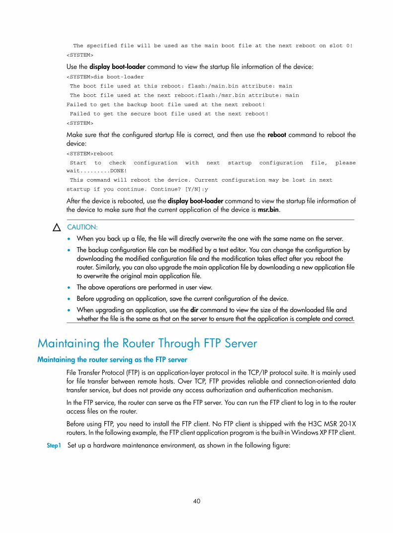
The specified file will be used as the main boot file at the next reboot on slot 0!
<SYSTEM>
Use the display boot-loader command to view the startup file information of the device: <SYSTEM>dis boot-loader
The boot file used at this reboot: flash:/main.bin attribute: main
The boot file used at the next reboot:flash:/msr.bin attribute: main
Failed to get the backup boot file used at the next reboot!
Failed to get the secure boot file used at the next reboot!
<SYSTEM>
Make sure that the configured startup file is correct, and then use the reboot command to reboot the device: <SYSTEM>reboot
Start to check configuration with next startup configuration file, please
wait.........DONE!
This command will reboot the device. Current configuration may be lost in next
startup if you continue. Continue? [Y/N]:y
After the device is rebooted, use the display boot-loader command to view the startup file information of the device to make sure that the current application of the device is msr.bin.
CAUTION:
• When you back up a file, the file will directly overwrite the one with the same name on the server.
• The backup configuration file can be modified by a text editor. You can change the configuration by downloading the modified configuration file and the modification takes effect after you reboot the router. Similarly, you can also upgrade the main application file by downloading a new application fileto overwrite the original main application file.
• The above operations are performed in user view.
• Before upgrading an application, save the current configuration of the device.
• When upgrading an application, use the dir command to view the size of the downloaded file and whether the file is the same as that on the server to ensure that the application is complete and correct.
Maintaining the Router Through FTP Server Maintaining the router serving as the FTP server
File Transfer Protocol (FTP) is an application-layer protocol in the TCP/IP protocol suite. It is mainly used for file transfer between remote hosts. Over TCP, FTP provides reliable and connection-oriented data transfer service, but does not provide any access authorization and authentication mechanism.
In the FTP service, the router can serve as the FTP server. You can run the FTP client to log in to the router access files on the router.
Before using FTP, you need to install the FTP client. No FTP client is shipped with the H3C MSR 20-1X routers. In the following example, the FTP client application program is the built-in Windows XP FTP client.
Step1 Set up a hardware maintenance environment, as shown in the following figure:
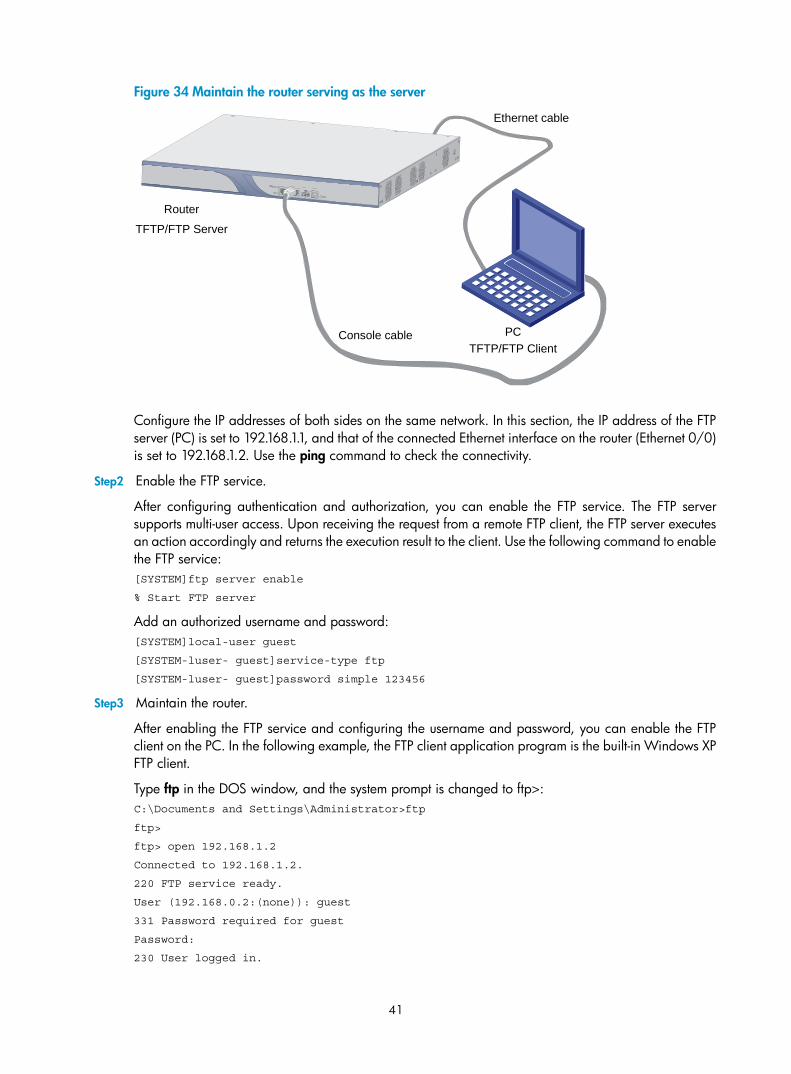
41
Figure 34 Maintain the router serving as the server
Ethernet cable
Router
PCConsole cable
TFTP/FTP Server
TFTP/FTP Client
Configure the IP addresses of both sides on the same network. In this section, the IP address of the FTP server (PC) is set to 192.168.1.1, and that of the connected Ethernet interface on the router (Ethernet 0/0) is set to 192.168.1.2. Use the ping command to check the connectivity.
Step2 Enable the FTP service.
After configuring authentication and authorization, you can enable the FTP service. The FTP server supports multi-user access. Upon receiving the request from a remote FTP client, the FTP server executes an action accordingly and returns the execution result to the client. Use the following command to enable the FTP service: [SYSTEM]ftp server enable
% Start FTP server
Add an authorized username and password: [SYSTEM]local-user guest
[SYSTEM-luser- guest]service-type ftp
[SYSTEM-luser- guest]password simple 123456
Step3 Maintain the router.
After enabling the FTP service and configuring the username and password, you can enable the FTP client on the PC. In the following example, the FTP client application program is the built-in Windows XP FTP client.
Type ftp in the DOS window, and the system prompt is changed to ftp>: C:\Documents and Settings\Administrator>ftp
ftp>
ftp> open 192.168.1.2
Connected to 192.168.1.2.
220 FTP service ready.
User (192.168.0.2:(none)): guest
331 Password required for guest
Password:
230 User logged in.
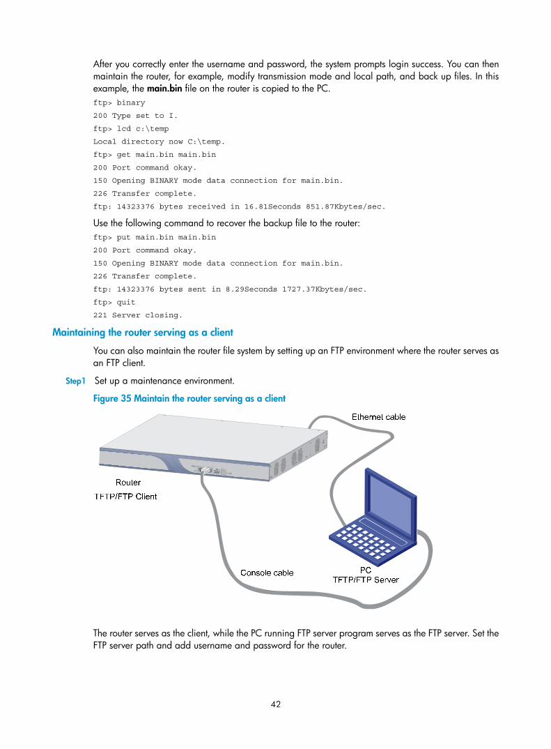
42
After you correctly enter the username and password, the system prompts login success. You can then maintain the router, for example, modify transmission mode and local path, and back up files. In this example, the main.bin file on the router is copied to the PC. ftp> binary
200 Type set to I.
ftp> lcd c:\temp
Local directory now C:\temp.
ftp> get main.bin main.bin
200 Port command okay.
150 Opening BINARY mode data connection for main.bin.
226 Transfer complete.
ftp: 14323376 bytes received in 16.81Seconds 851.87Kbytes/sec.
Use the following command to recover the backup file to the router: ftp> put main.bin main.bin
200 Port command okay.
150 Opening BINARY mode data connection for main.bin.
226 Transfer complete.
ftp: 14323376 bytes sent in 8.29Seconds 1727.37Kbytes/sec.
ftp> quit
221 Server closing.
Maintaining the router serving as a client
You can also maintain the router file system by setting up an FTP environment where the router serves as an FTP client.
Step1 Set up a maintenance environment.
Figure 35 Maintain the router serving as a client
The router serves as the client, while the PC running FTP server program serves as the FTP server. Set the FTP server path and add username and password for the router.
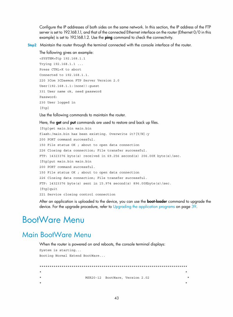
43
Configure the IP addresses of both sides on the same network. In this section, the IP address of the FTP server is set to 192.168.1.1, and that of the connected Ethernet interface on the router (Ethernet 0/0 in this example) is set to 192.168.1.2. Use the ping command to check the connectivity.
Step2 Maintain the router through the terminal connected with the console interface of the router.
The following gives an example: <SYSTEM>ftp 192.168.1.1
Trying 192.168.1.1 ...
Press CTRL+K to abort
Connected to 192.168.1.1.
220 3Com 3CDaemon FTP Server Version 2.0
User(192.168.1.1:(none)):guest
331 User name ok, need password
Password:
230 User logged in
[ftp]
Use the following commands to maintain the router.
Here, the get and put commands are used to restore and back up files. [ftp]get main.bin main.bin
flash:/main.bin has been existing. Overwrite it?[Y/N]:y
200 PORT command successful.
150 File status OK ; about to open data connection
226 Closing data connection; File transfer successful.
FTP: 14323376 byte(s) received in 69.256 second(s) 206.00K byte(s)/sec.
[ftp]put main.bin main.bin
200 PORT command successful.
150 File status OK ; about to open data connection
226 Closing data connection; File transfer successful.
FTP: 14323376 byte(s) sent in 15.974 second(s) 896.00Kbyte(s)/sec.
[ftp]quit
221 Service closing control connection
After an application is uploaded to the device, you can use the boot-loader command to upgrade the device. For the upgrade procedure, refer to Upgrading the application programs on page 39.
BootWare Menu
Main BootWare Menu When the router is powered on and reboots, the console terminal displays: System is starting...
Booting Normal Extend BootWare...
**************************************************************************
* *
* MSR20-12 BootWare, Version 2.02 *
* *
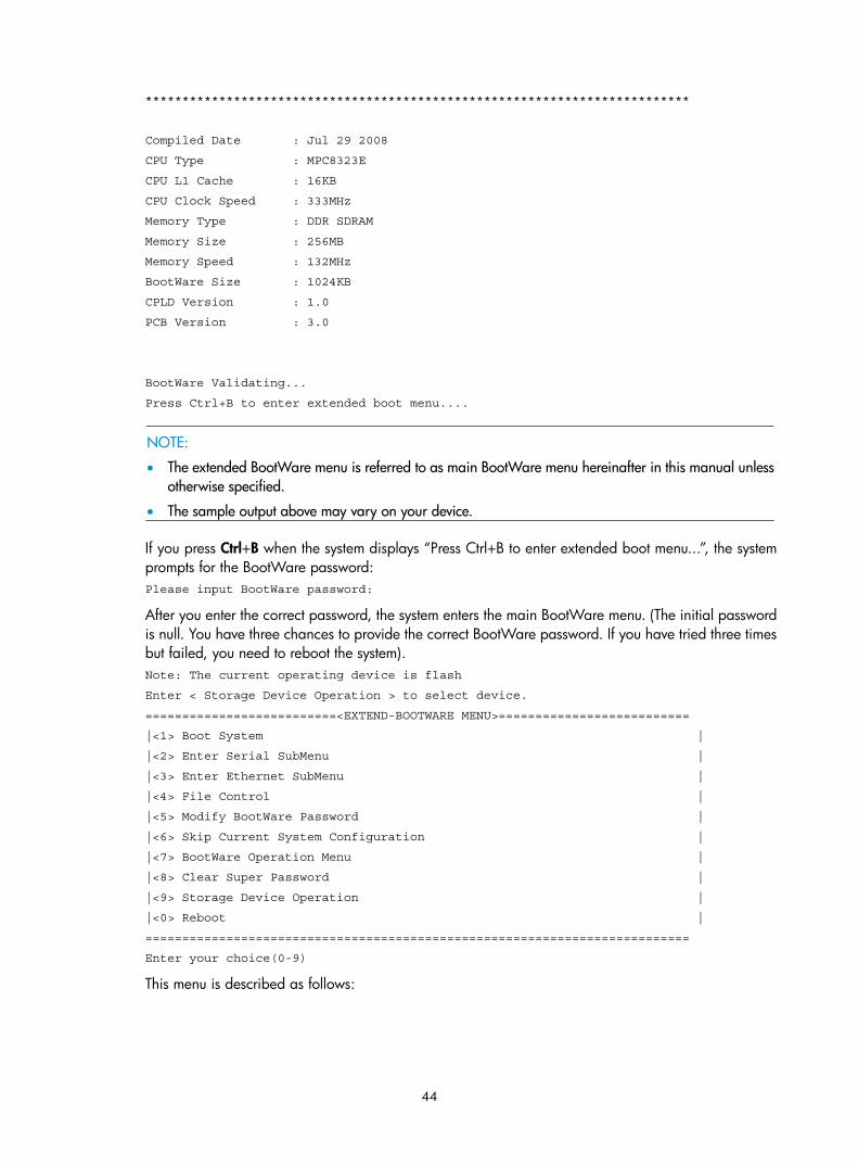
44
**************************************************************************
Compiled Date : Jul 29 2008
CPU Type : MPC8323E
CPU L1 Cache : 16KB
CPU Clock Speed : 333MHz
Memory Type : DDR SDRAM
Memory Size : 256MB
Memory Speed : 132MHz
BootWare Size : 1024KB
CPLD Version : 1.0
PCB Version : 3.0
BootWare Validating...
Press Ctrl+B to enter extended boot menu....
NOTE:
• The extended BootWare menu is referred to as main BootWare menu hereinafter in this manual unlessotherwise specified.
• The sample output above may vary on your device.
If you press Ctrl+B when the system displays “Press Ctrl+B to enter extended boot menu...”, the system prompts for the BootWare password: Please input BootWare password:
After you enter the correct password, the system enters the main BootWare menu. (The initial password is null. You have three chances to provide the correct BootWare password. If you have tried three times but failed, you need to reboot the system). Note: The current operating device is flash
Enter < Storage Device Operation > to select device.
==========================<EXTEND-BOOTWARE MENU>==========================
|<1> Boot System |
|<2> Enter Serial SubMenu |
|<3> Enter Ethernet SubMenu |
|<4> File Control |
|<5> Modify BootWare Password |
|<6> Skip Current System Configuration |
|<7> BootWare Operation Menu |
|<8> Clear Super Password |
|<9> Storage Device Operation |
|<0> Reboot |
==========================================================================
Enter your choice(0-9)
This menu is described as follows:
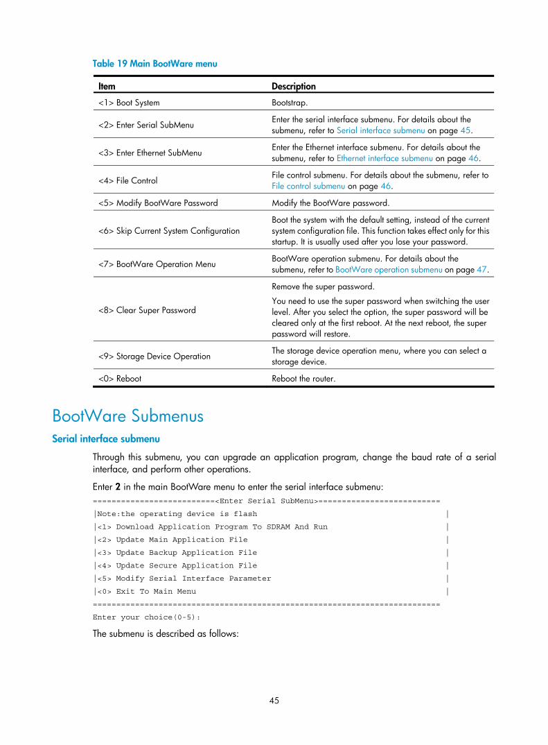
45
Table 19 Main BootWare menu
Item Description
<1> Boot System Bootstrap.
<2> Enter Serial SubMenu Enter the serial interface submenu. For details about the submenu, refer to Serial interface submenu on page 45.
<3> Enter Ethernet SubMenu Enter the Ethernet interface submenu. For details about the submenu, refer to Ethernet interface submenu on page 46.
<4> File Control File control submenu. For details about the submenu, refer to File control submenu on page 46.
<5> Modify BootWare Password Modify the BootWare password.
<6> Skip Current System Configuration Boot the system with the default setting, instead of the current system configuration file. This function takes effect only for this startup. It is usually used after you lose your password.
<7> BootWare Operation Menu BootWare operation submenu. For details about the submenu, refer to BootWare operation submenu on page 47.
<8> Clear Super Password
Remove the super password.
You need to use the super password when switching the user level. After you select the option, the super password will be cleared only at the first reboot. At the next reboot, the super password will restore.
<9> Storage Device Operation The storage device operation menu, where you can select a storage device.
<0> Reboot Reboot the router.
BootWare Submenus Serial interface submenu
Through this submenu, you can upgrade an application program, change the baud rate of a serial interface, and perform other operations.
Enter 2 in the main BootWare menu to enter the serial interface submenu: ==========================<Enter Serial SubMenu>==========================
|Note:the operating device is flash |
|<1> Download Application Program To SDRAM And Run |
|<2> Update Main Application File |
|<3> Update Backup Application File |
|<4> Update Secure Application File |
|<5> Modify Serial Interface Parameter |
|<0> Exit To Main Menu |
==========================================================================
Enter your choice(0-5):
The submenu is described as follows:
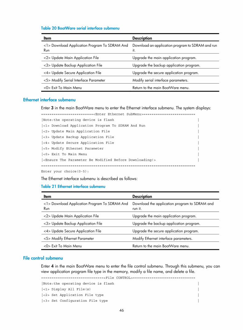
46
Table 20 BootWare serial interface submenu
Item Description
<1> Download Application Program To SDRAM And Run
Download an application program to SDRAM and run it.
<2> Update Main Application File Upgrade the main application program.
<3> Update Backup Application File Upgrade the backup application program.
<4> Update Secure Application File Upgrade the secure application program.
<5> Modify Serial Interface Parameter Modify serial interface parameters.
<0> Exit To Main Menu Return to the main BootWare menu.
Ethernet interface submenu
Enter 3 in the main BootWare menu to enter the Ethernet interface submenu. The system displays: =========================<Enter Ethernet SubMenu>=========================
|Note:the operating device is flash |
|<1> Download Application Program To SDRAM And Run |
|<2> Update Main Application File |
|<3> Update Backup Application File |
|<4> Update Secure Application File |
|<5> Modify Ethernet Parameter |
|<0> Exit To Main Menu |
|<Ensure The Parameter Be Modified Before Downloading!> |
==========================================================================
Enter your choice(0-5):
The Ethernet interface submenu is described as follows:
Table 21 Ethernet interface submenu
Item Description
<1> Download Application Program To SDRAM And Run
Download the application program to SDRAM and run it.
<2> Update Main Application File Upgrade the main application program.
<3> Update Backup Application File Upgrade the backup application program.
<4> Update Secure Application File Upgrade the secure application program.
<5> Modify Ethernet Parameter Modify Ethernet interface parameters.
<0> Exit To Main Menu Return to the main BootWare menu.
File control submenu
Enter 4 in the main BootWare menu to enter the file control submenu. Through this submenu, you can view application program file type in the memory, modify a file name, and delete a file. ==============================<File CONTROL>==============================
|Note:the operating device is flash |
|<1> Display All File(s) |
|<2> Set Application File type |
|<3> Set Configuration File type |
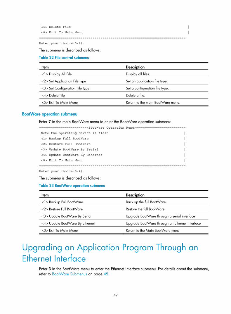
47
|<4> Delete File |
|<0> Exit To Main Menu |
==========================================================================
Enter your choice(0-4):
The submenu is described as follows:
Table 22 File control submenu
Item Description
<1> Display All File Display all files.
<2> Set Application File type Set an application file type.
<3> Set Configuration File type Set a configuration file type.
<4> Delete File Delete a file.
<5> Exit To Main Menu Return to the main BootWare menu.
BootWare operation submenu
Enter 7 in the main BootWare menu to enter the BootWare operation submenu: ========================<BootWare Operation Menu>=========================
|Note:the operating device is flash |
|<1> Backup Full BootWare |
|<2> Restore Full BootWare |
|<3> Update BootWare By Serial |
|<4> Update BootWare By Ethernet |
|<0> Exit To Main Menu |
==========================================================================
Enter your choice(0-4):
The submenu is described as follows:
Table 23 BootWare operation submenu
Item Description
<1> Backup Full BootWare Back up the full BootWare.
<2> Restore Full BootWare Restore the full BootWare.
<3> Update BootWare By Serial Upgrade BootWare through a serial interface
<4> Update BootWare By Ethernet Upgrade BootWare through an Ethernet interface
<0> Exit To Main Menu Return to the Main BootWare menu
Upgrading an Application Program Through an Ethernet Interface
Enter 3 in the BootWare menu to enter the Ethernet interface submenu. For details about the submenu, refer to BootWare Submenus on page 45.
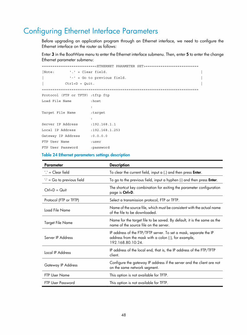
48
Configuring Ethernet Interface Parameters Before upgrading an application program through an Ethernet interface, we need to configure the Ethernet interface on the router as follows:
Enter 3 in the BootWare menu to enter the Ethernet interface submenu. Then, enter 5 to enter the change Ethernet parameter submenu: =========================<ETHERNET PARAMETER SET>=========================
|Note: '.' = Clear field. |
| '-' = Go to previous field. |
| Ctrl+D = Quit. |
==========================================================================
Protocol (FTP or TFTP) :tftp ftp
Load File Name :host
:
Target File Name :target
:
Server IP Address :192.168.1.1
Local IP Address :192.168.1.253
Gateway IP Address :0.0.0.0
FTP User Name :user
FTP User Password :password
Table 24 Ethernet parameters settings description
Parameter Description
'.' = Clear field To clear the current field, input a (.) and then press Enter.
'-' = Go to previous field To go to the previous field, input a hyphen (-) and then press Enter.
Ctrl+D = Quit The shortcut key combination for exiting the parameter configuration page is Ctrl+D.
Protocol (FTP or TFTP) Select a transmission protocol, FTP or TFTP.
Load File Name Name of the source file, which must be consistent with the actual name of the file to be downloaded.
Target File Name Name for the target file to be saved. By default, it is the same as the name of the source file on the server.
Server IP Address IP address of the FTP/TFTP server. To set a mask, separate the IP address from the mask with a colon (:), for example, 192.168.80.10:24.
Local IP Address IP address of the local end, that is, the IP address of the FTP/TFTP client.
Gateway IP Address Configure the gateway IP address if the server and the client are not on the same network segment.
FTP User Name This option is not available for TFTP.
FTP User Password This option is not available for TFTP.
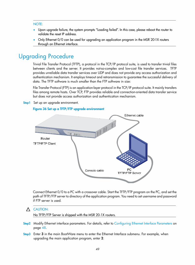
49
NOTE:
• Upon upgrade failure, the system prompts “Loading failed”. In this case, please reboot the router to validate the reset IP address.
• Only Ethernet 0/0 can be used for upgrading an application program in the MSR 20-1X routers through an Ethernet interface.
Upgrading Procedure Trivial File Transfer Protocol (TFTP), a protocol in the TCP/IP protocol suite, is used to transfer trivial files between clients and the server. It provides not-so-complex and low-cost file transfer services. TFTP provides unreliable data transfer services over UDP and does not provide any access authorization and authentication mechanism. It employs timeout and retransmission to guarantee the successful delivery of data. The TFTP software is much smaller than the FTP software in size:
File Transfer Protocol (FTP) is an application-layer protocol in the TCP/IP protocol suite. It mainly transfers files among remote hosts. Over TCP, FTP provides reliable and connection-oriented data transfer service but does not provide access authorization and authentication mechanism.
Step1 Set up an upgrade environment.
Figure 36 Set up a TFTP/FTP upgrade environment
Connect Ethernet 0/0 to a PC with a crossover cable. Start the TFTP/FTP program on the PC, and set the path of TFTP/FTP server to directory of the application program. You need to set username and password if FTP server is used.
CAUTION:
No TFTP/FTP Server is shipped with the MSR 20-1X routers.
Step2 Modify Ethernet interface parameters. For details, refer to Configuring Ethernet Interface Parameters on page 48.
Step3 Enter 3 in the main BootWare menu to enter the Ethernet Interface submenu. For example, when upgrading the main application program, enter 2:
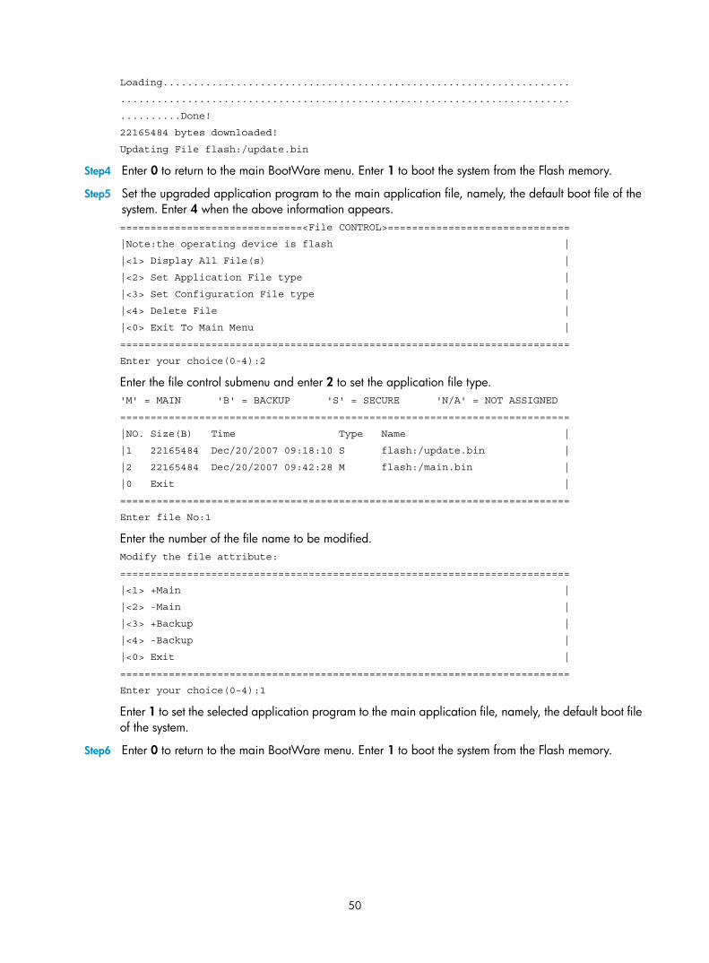
50
Loading...................................................................
..........................................................................
..........Done!
22165484 bytes downloaded!
Updating File flash:/update.bin
Step4 Enter 0 to return to the main BootWare menu. Enter 1 to boot the system from the Flash memory.
Step5 Set the upgraded application program to the main application file, namely, the default boot file of the system. Enter 4 when the above information appears. ==============================<File CONTROL>==============================
|Note:the operating device is flash |
|<1> Display All File(s) |
|<2> Set Application File type |
|<3> Set Configuration File type |
|<4> Delete File |
|<0> Exit To Main Menu |
==========================================================================
Enter your choice(0-4):2
Enter the file control submenu and enter 2 to set the application file type. 'M' = MAIN 'B' = BACKUP 'S' = SECURE 'N/A' = NOT ASSIGNED
==========================================================================
|NO. Size(B) Time Type Name |
|1 22165484 Dec/20/2007 09:18:10 S flash:/update.bin |
|2 22165484 Dec/20/2007 09:42:28 M flash:/main.bin |
|0 Exit |
==========================================================================
Enter file No:1
Enter the number of the file name to be modified. Modify the file attribute:
==========================================================================
|<1> +Main |
|<2> -Main |
|<3> +Backup |
|<4> -Backup |
|<0> Exit |
==========================================================================
Enter your choice(0-4):1
Enter 1 to set the selected application program to the main application file, namely, the default boot file of the system.
Step6 Enter 0 to return to the main BootWare menu. Enter 1 to boot the system from the Flash memory.
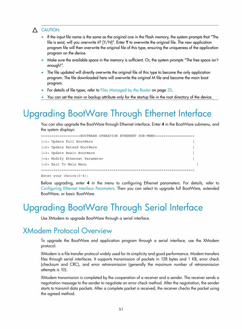
51
CAUTION:
• If the input file name is the same as the original one in the Flash memory, the system prompts that “Thefile is exist, will you overwrite it? [Y/N]”. Enter Y to overwrite the original file. The new application program file will then overwrite the original file of this type, ensuring the uniqueness of the applicationprogram on the device.
• Make sure the available space in the memory is sufficient. Or, the system prompts “The free space isn'tenough!”.
• The file updated will directly overwrite the original file of this type to become the only application program. The file downloaded here will overwrite the original M file and become the main boot program.
• For details of file types, refer to Files Managed by the Router on page 35.
• You can set the main or backup attribute only for the startup file in the root directory of the device.
Upgrading BootWare Through Ethernet Interface You can also upgrade the BootWare through Ethernet interface. Enter 4 in the BootWare submenu, and the system displays: ==================<BOOTWARE OPERATION ETHERNET SUB-MENU>==================
|<1> Update Full BootWare |
|<2> Update Extend BootWare |
|<3> Update Basic BootWare |
|<4> Modify Ethernet Parameter |
|<0> Exit To Main Menu |
==========================================================================
Enter your choice(0-4):
Before upgrading, enter 4 in the menu to configuring Ethernet parameters. For details, refer to Configuring Ethernet Interface Parameters. Then you can select to upgrade full BootWare, extended BootWare, or basic BootWare.
Upgrading BootWare Through Serial Interface Use XModem to upgrade BootWare through a serial interface.
XModem Protocol Overview To upgrade the BootWare and application program through a serial interface, use the XModem protocol.
XModem is a file transfer protocol widely used for its simplicity and good performance. Modem transfers files through serial interfaces. It supports transmission of packets in 128 bytes and 1 KB, error check (checksum and CRC), and error retransmission (generally the maximum number of retransmission attempts is 10).
XModem transmission is completed by the cooperation of a receiver and a sender. The receiver sends a negotiation message to the sender to negotiate an error check method. After the negotiation, the sender starts to transmit data packets. After a complete packet is received, the receiver checks the packet using the agreed method.
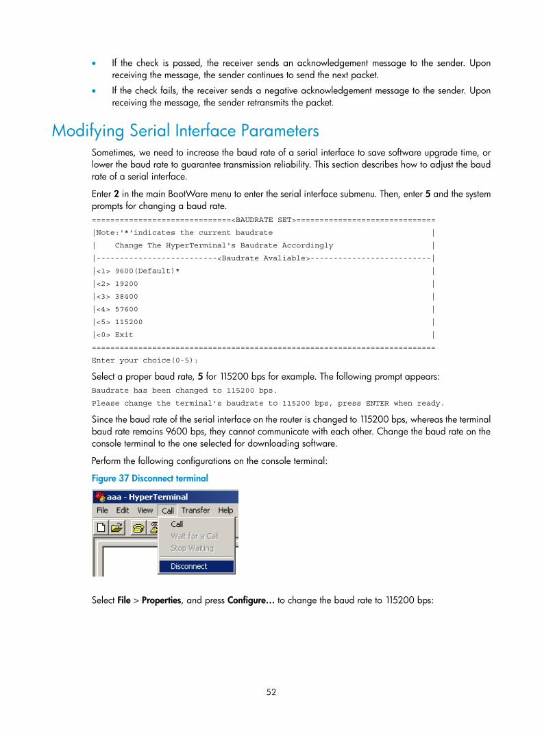
52
• If the check is passed, the receiver sends an acknowledgement message to the sender. Upon receiving the message, the sender continues to send the next packet.
• If the check fails, the receiver sends a negative acknowledgement message to the sender. Upon receiving the message, the sender retransmits the packet.
Modifying Serial Interface Parameters Sometimes, we need to increase the baud rate of a serial interface to save software upgrade time, or lower the baud rate to guarantee transmission reliability. This section describes how to adjust the baud rate of a serial interface.
Enter 2 in the main BootWare menu to enter the serial interface submenu. Then, enter 5 and the system prompts for changing a baud rate. ==============================<BAUDRATE SET>==============================
|Note:'*'indicates the current baudrate |
| Change The HyperTerminal's Baudrate Accordingly |
|--------------------------<Baudrate Avaliable>--------------------------|
|<1> 9600(Default)* |
|<2> 19200 |
|<3> 38400 |
|<4> 57600 |
|<5> 115200 |
|<0> Exit |
==========================================================================
Enter your choice(0-5):
Select a proper baud rate, 5 for 115200 bps for example. The following prompt appears: Baudrate has been changed to 115200 bps.
Please change the terminal's baudrate to 115200 bps, press ENTER when ready.
Since the baud rate of the serial interface on the router is changed to 115200 bps, whereas the terminal baud rate remains 9600 bps, they cannot communicate with each other. Change the baud rate on the console terminal to the one selected for downloading software.
Perform the following configurations on the console terminal:
Figure 37 Disconnect terminal
Select File > Properties, and press Configure… to change the baud rate to 115200 bps:
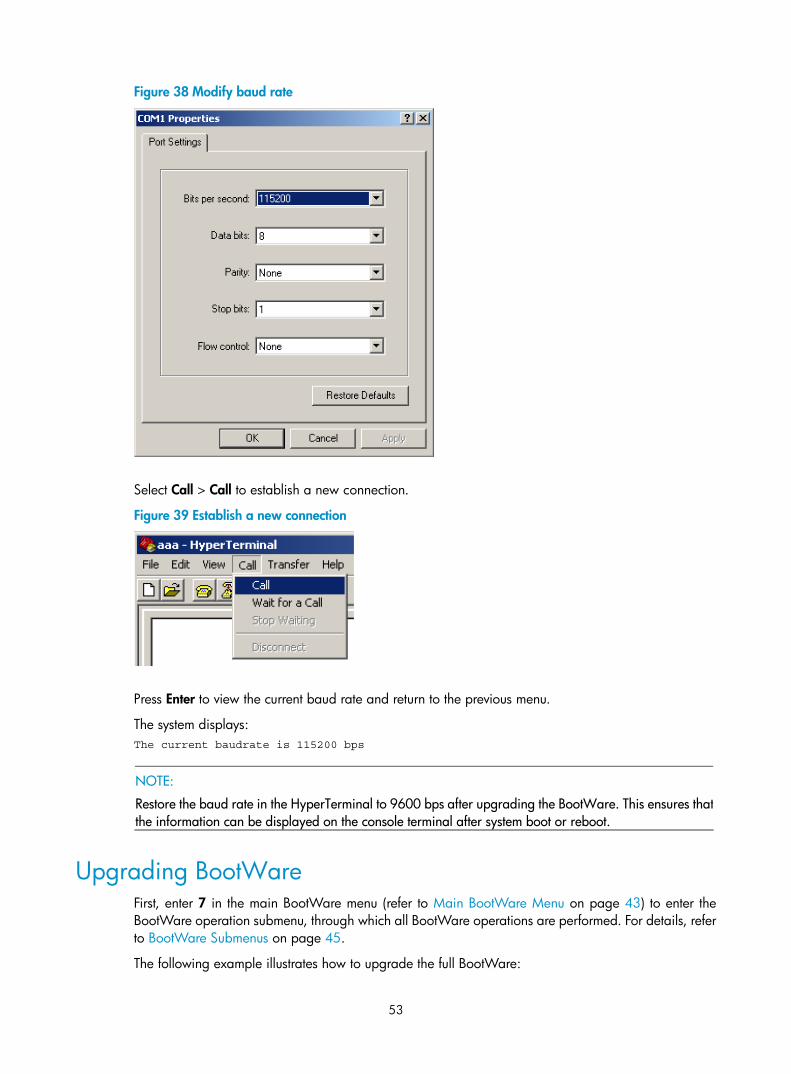
53
Figure 38 Modify baud rate
Select Call > Call to establish a new connection.
Figure 39 Establish a new connection
Press Enter to view the current baud rate and return to the previous menu.
The system displays: The current baudrate is 115200 bps
NOTE:
Restore the baud rate in the HyperTerminal to 9600 bps after upgrading the BootWare. This ensures thatthe information can be displayed on the console terminal after system boot or reboot.
Upgrading BootWare First, enter 7 in the main BootWare menu (refer to Main BootWare Menu on page 43) to enter the BootWare operation submenu, through which all BootWare operations are performed. For details, refer to BootWare Submenus on page 45.
The following example illustrates how to upgrade the full BootWare:
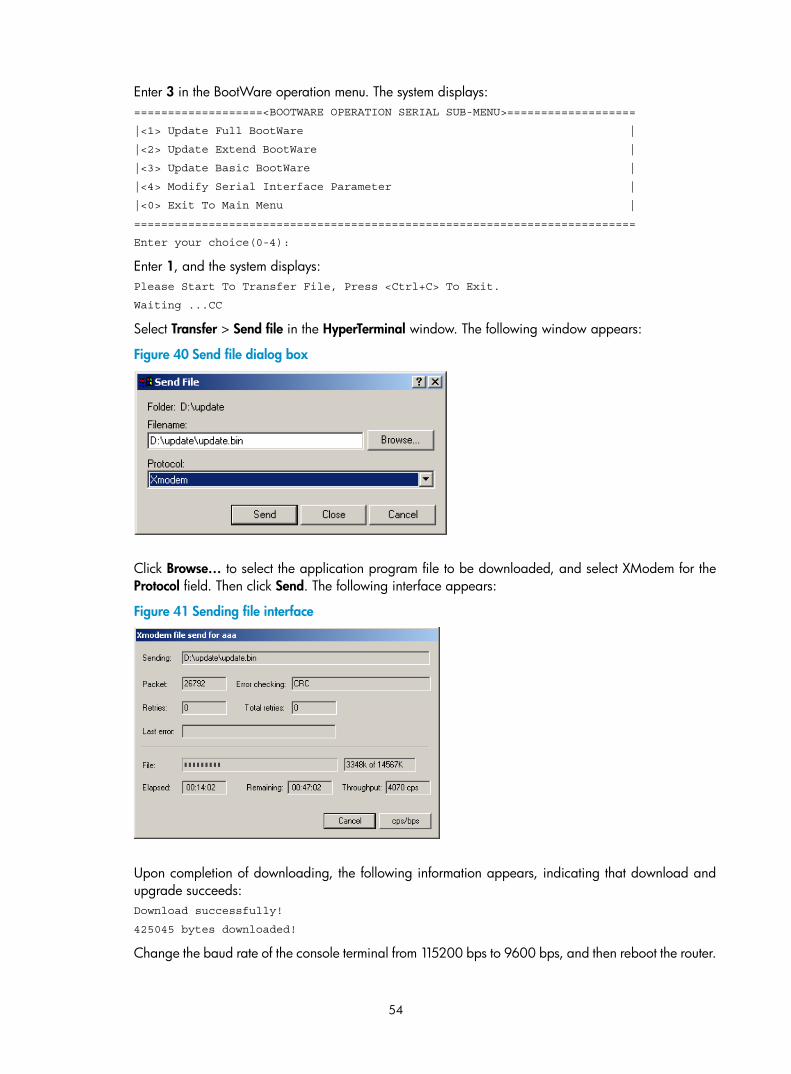
54
Enter 3 in the BootWare operation menu. The system displays: ===================<BOOTWARE OPERATION SERIAL SUB-MENU>===================
|<1> Update Full BootWare |
|<2> Update Extend BootWare |
|<3> Update Basic BootWare |
|<4> Modify Serial Interface Parameter |
|<0> Exit To Main Menu |
==========================================================================
Enter your choice(0-4):
Enter 1, and the system displays: Please Start To Transfer File, Press <Ctrl+C> To Exit.
Waiting ...CC
Select Transfer > Send file in the HyperTerminal window. The following window appears:
Figure 40 Send file dialog box
Click Browse… to select the application program file to be downloaded, and select XModem for the Protocol field. Then click Send. The following interface appears:
Figure 41 Sending file interface
Upon completion of downloading, the following information appears, indicating that download and upgrade succeeds: Download successfully!
425045 bytes downloaded!
Change the baud rate of the console terminal from 115200 bps to 9600 bps, and then reboot the router.
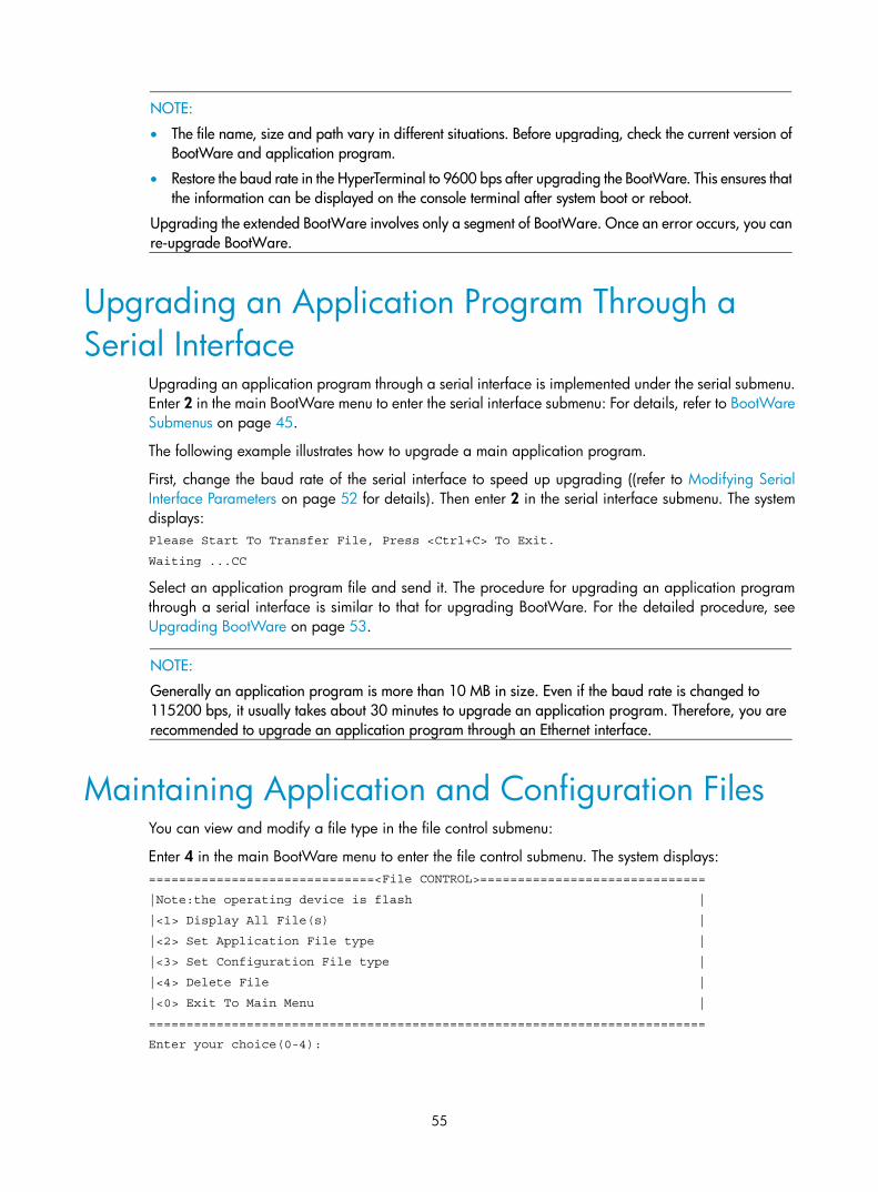
55
NOTE:
• The file name, size and path vary in different situations. Before upgrading, check the current version ofBootWare and application program.
• Restore the baud rate in the HyperTerminal to 9600 bps after upgrading the BootWare. This ensures thatthe information can be displayed on the console terminal after system boot or reboot.
Upgrading the extended BootWare involves only a segment of BootWare. Once an error occurs, you canre-upgrade BootWare.
Upgrading an Application Program Through a Serial Interface
Upgrading an application program through a serial interface is implemented under the serial submenu. Enter 2 in the main BootWare menu to enter the serial interface submenu: For details, refer to BootWare Submenus on page 45.
The following example illustrates how to upgrade a main application program.
First, change the baud rate of the serial interface to speed up upgrading ((refer to Modifying Serial Interface Parameters on page 52 for details). Then enter 2 in the serial interface submenu. The system displays: Please Start To Transfer File, Press <Ctrl+C> To Exit.
Waiting ...CC
Select an application program file and send it. The procedure for upgrading an application program through a serial interface is similar to that for upgrading BootWare. For the detailed procedure, see Upgrading BootWare on page 53.
NOTE:
Generally an application program is more than 10 MB in size. Even if the baud rate is changed to 115200 bps, it usually takes about 30 minutes to upgrade an application program. Therefore, you are recommended to upgrade an application program through an Ethernet interface.
Maintaining Application and Configuration Files You can view and modify a file type in the file control submenu:
Enter 4 in the main BootWare menu to enter the file control submenu. The system displays: ==============================<File CONTROL>==============================
|Note:the operating device is flash |
|<1> Display All File(s) |
|<2> Set Application File type |
|<3> Set Configuration File type |
|<4> Delete File |
|<0> Exit To Main Menu |
==========================================================================
Enter your choice(0-4):
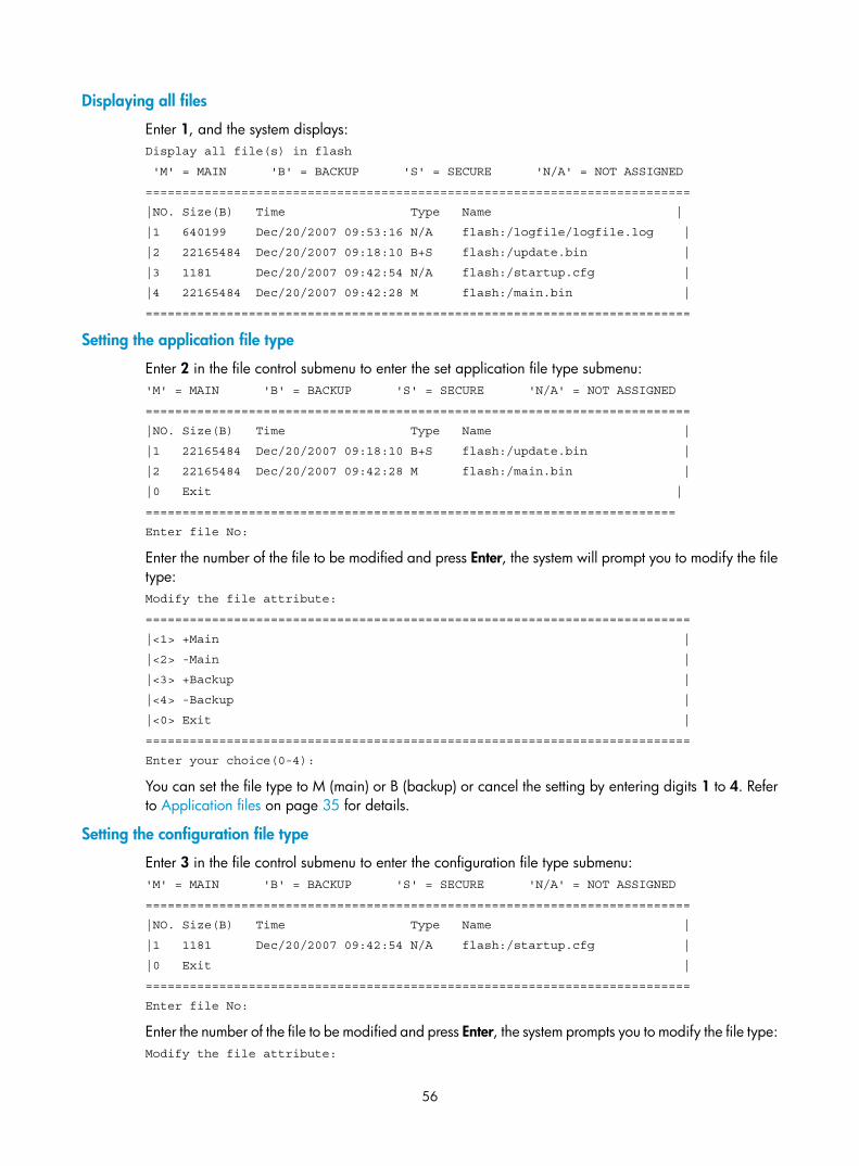
56
Displaying all files
Enter 1, and the system displays: Display all file(s) in flash
'M' = MAIN 'B' = BACKUP 'S' = SECURE 'N/A' = NOT ASSIGNED
==========================================================================
|NO. Size(B) Time Type Name |
|1 640199 Dec/20/2007 09:53:16 N/A flash:/logfile/logfile.log |
|2 22165484 Dec/20/2007 09:18:10 B+S flash:/update.bin |
|3 1181 Dec/20/2007 09:42:54 N/A flash:/startup.cfg |
|4 22165484 Dec/20/2007 09:42:28 M flash:/main.bin |
==========================================================================
Setting the application file type
Enter 2 in the file control submenu to enter the set application file type submenu: 'M' = MAIN 'B' = BACKUP 'S' = SECURE 'N/A' = NOT ASSIGNED
==========================================================================
|NO. Size(B) Time Type Name |
|1 22165484 Dec/20/2007 09:18:10 B+S flash:/update.bin |
|2 22165484 Dec/20/2007 09:42:28 M flash:/main.bin |
|0 Exit |
========================================================================
Enter file No:
Enter the number of the file to be modified and press Enter, the system will prompt you to modify the file type: Modify the file attribute:
==========================================================================
|<1> +Main |
|<2> -Main |
|<3> +Backup |
|<4> -Backup |
|<0> Exit |
==========================================================================
Enter your choice(0-4):
You can set the file type to M (main) or B (backup) or cancel the setting by entering digits 1 to 4. Refer to Application files on page 35 for details.
Setting the configuration file type
Enter 3 in the file control submenu to enter the configuration file type submenu: 'M' = MAIN 'B' = BACKUP 'S' = SECURE 'N/A' = NOT ASSIGNED
==========================================================================
|NO. Size(B) Time Type Name |
|1 1181 Dec/20/2007 09:42:54 N/A flash:/startup.cfg |
|0 Exit |
==========================================================================
Enter file No:
Enter the number of the file to be modified and press Enter, the system prompts you to modify the file type: Modify the file attribute:
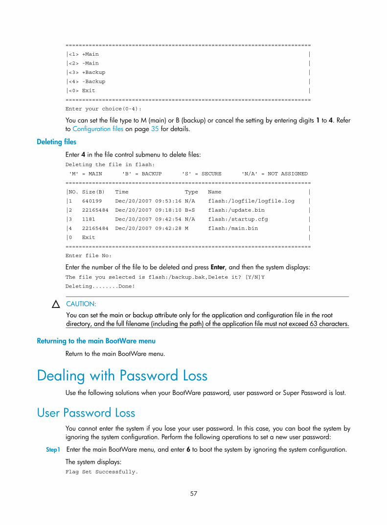
57
==========================================================================
|<1> +Main |
|<2> -Main |
|<3> +Backup |
|<4> -Backup |
|<0> Exit |
==========================================================================
Enter your choice(0-4):
You can set the file type to M (main) or B (backup) or cancel the setting by entering digits 1 to 4. Refer to Configuration files on page 35 for details.
Deleting files
Enter 4 in the file control submenu to delete files: Deleting the file in flash:
'M' = MAIN 'B' = BACKUP 'S' = SECURE 'N/A' = NOT ASSIGNED
==========================================================================
|NO. Size(B) Time Type Name |
|1 640199 Dec/20/2007 09:53:16 N/A flash:/logfile/logfile.log |
|2 22165484 Dec/20/2007 09:18:10 B+S flash:/update.bin |
|3 1181 Dec/20/2007 09:42:54 N/A flash:/startup.cfg |
|4 22165484 Dec/20/2007 09:42:28 M flash:/main.bin |
|0 Exit |
==========================================================================
Enter file No:
Enter the number of the file to be deleted and press Enter, and then the system displays: The file you selected is flash:/backup.bak,Delete it? [Y/N]Y
Deleting........Done!
CAUTION:
You can set the main or backup attribute only for the application and configuration file in the root directory, and the full filename (including the path) of the application file must not exceed 63 characters.
Returning to the main BootWare menu
Return to the main BootWare menu.
Dealing with Password Loss Use the following solutions when your BootWare password, user password or Super Password is lost.
User Password Loss You cannot enter the system if you lose your user password. In this case, you can boot the system by ignoring the system configuration. Perform the following operations to set a new user password:
Step1 Enter the main BootWare menu, and enter 6 to boot the system by ignoring the system configuration.
The system displays: Flag Set Successfully.
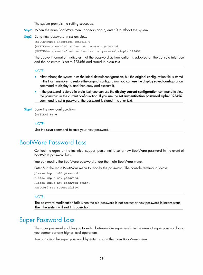
58
The system prompts the setting succeeds.
Step2 When the main BootWare menu appears again, enter 0 to reboot the system.
Step3 Set a new password in system view. [SYSTEM]user-interface console 0
[SYSTEM-ui-console0]authentication-mode password
[SYSTEM-ui-console0]set authentication password simple 123456
The above information indicates that the password authentication is adopted on the console interface and the password is set to 123456 and stored in plain text.
NOTE:
• After reboot, the system runs the initial default configuration, but the original configuration file is storedin the Flash memory. To restore the original configuration, you can use the display saved-configurationcommand to display it, and then copy and execute it.
• If the password is stored in plain text, you can use the display current-configuration command to viewthe password in the current configuration. If you use the set authentication password cipher 123456 command to set a password, the password is stored in cipher text.
Step4 Save the new configuration. [SYSTEM] save
NOTE:
Use the save command to save your new password.
BootWare Password Loss Contact the agent or the technical support personnel to set a new BootWare password in the event of BootWare password loss.
You can modify the BootWare password under the main BootWare menu.
Enter 5 in the main BootWare menu to modify the password: The console terminal displays: please input old password:
Please input new password:
Please input new password again:
Password Set Successfully.
NOTE:
The password modification fails when the old password is not correct or new password is inconsistent. Then the system will exit this operation.
Super Password Loss The super password enables you to switch between four super levels. In the event of super password loss, you cannot perform higher level operations.
You can clear the super password by entering 8 in the main BootWare menu.

59
After you clear the super password, quit the menu and reboot the router, you can directly enter system view. The setting is valid for the first reboot of the router only. The super password will be restored after a second reboot.
Backing Up and Restoring BootWare The MSR 20-1X routers do not support backup and restoration of BootWare.
60
Hardware Maintenance
Preparing Tools • Phillips screwdrivers
• Flathead screwdrivers
• ESD-preventive wrist strap
• Antistatic bag
NOTE:
The above tools are not shipped with the MSR 20-1X routers. You must prepare them by yourself.
Opening the Chassis Cover Follow these steps to open the chassis cover:
Step1 Power off the router and remove the power cord.
Step2 Remove all cables from interface cards on the rear panel (keep the grounding cable connected).
Step3 Put the router on a table and have the rear panel face you. Loosen and remove the captive screws from the rear panel with a Phillips screwdriver.
Step4 Put two flathead screwdrivers into the holes on both sides of the chassis and turn them until the tab on the front panel is separated from the front panel.
Step5 Pull the cover horizontally a short distance, lift and remove it.
WARNING!
• A dismantle-preventive seal is stuck on one of the screws of the router chassis. When you ask your salesagent to maintain the router, you must ensure that the dismantlement-preventive seal on the screw is intact.
• The following procedure can only be carried out by a qualified service engineer.
• Please read the safety instructions provided with this router before carrying out this work.
• Ensure that no power is present for the sake of safety before maintaining the hardware.
• Wear an ESD-preventive wrist strap and make sure that it makes good skin contact when maintaining the hardware.
• Only memory modules provided by our company are recommended for use. Otherwise, the router mayoperate improperly.
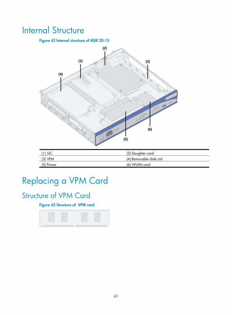
61
Internal Structure Figure 42 Internal structure of MSR 20-15
(1)
(2)
(3)
(4)
(5)
(6)
(1) SIC (2) Daughter card (3) VPM (4) Removable slide rail (5) Power (6) WLAN card
Replacing a VPM Card
Structure of VPM Card Figure 43 Structure of VPM card
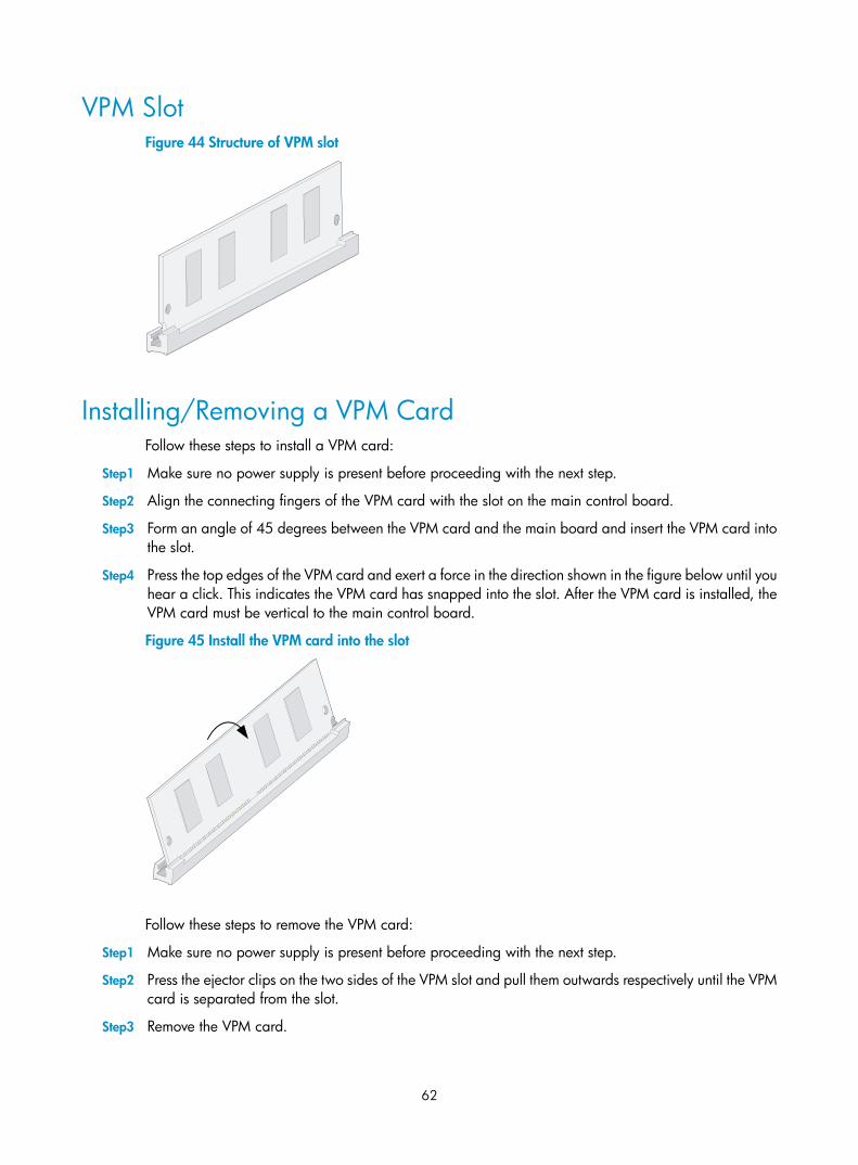
62
VPM Slot Figure 44 Structure of VPM slot
Installing/Removing a VPM Card Follow these steps to install a VPM card:
Step1 Make sure no power supply is present before proceeding with the next step.
Step2 Align the connecting fingers of the VPM card with the slot on the main control board.
Step3 Form an angle of 45 degrees between the VPM card and the main board and insert the VPM card into the slot.
Step4 Press the top edges of the VPM card and exert a force in the direction shown in the figure below until you hear a click. This indicates the VPM card has snapped into the slot. After the VPM card is installed, the VPM card must be vertical to the main control board.
Figure 45 Install the VPM card into the slot
Follow these steps to remove the VPM card:
Step1 Make sure no power supply is present before proceeding with the next step.
Step2 Press the ejector clips on the two sides of the VPM slot and pull them outwards respectively until the VPM card is separated from the slot.
Step3 Remove the VPM card.
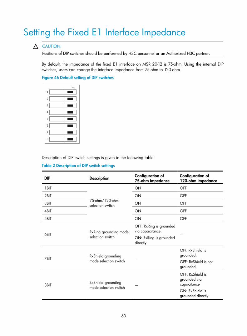
63
Setting the Fixed E1 Interface Impedance
CAUTION:
Positions of DIP switches should be performed by H3C personnel or an Authorized H3C partner.
By default, the impedance of the fixed E1 interface on MSR 20-12 is 75-ohm. Using the internal DIP switches, users can change the interface impedance from 75-ohm to 120-ohm.
Figure 46 Default setting of DIP switches
on
1
2
3
4
5
6
7
8
Description of DIP switch settings is given in the following table:
Table 2 Description of DIP switch settings
DIP Description Configuration of 75-ohm impedance
Configuration of 120-ohm impedance
1BIT ON OFF
2BIT ON OFF
3BIT ON OFF
4BIT ON OFF
5BIT
75-ohm/120-ohm selection switch
ON OFF
6BIT RxRing grounding mode selection switch
OFF: RxRing is grounded via capacitance.
ON: RxRing is grounded directly.
—
7BIT RxShield grounding mode selection switch —
ON: RxShield is grounded.
OFF: RxShield is not grounded.
8BIT SxShield grounding mode selection switch —
OFF: RxShield is grounded via capacitance
ON: RxShield is grounded directly.

64
CAUTION:
• It is recommended to select the DIP switch of the fixed E1 interface in this way: when connecting 75-ohmcable, flip BIT1-8 to ON, and when connecting 120-ohm cable, flip BIT1-8 to OFF.
• By default, all of the DIP switches are factory-configured to ON, that is, the impedance of E1 interfaceis 75-ohm.
65
Troubleshooting
Troubleshooting the Power System Symptom:
The PWR LED on the front panel is OFF.
Solution:
Check that:
• The power switch on the router is turned on.
• The switch of the power source is turned on.
• The power cord is correctly connected.
• The output voltage of the power source is compliant with the voltage indicated on the label of the router.
Troubleshooting the Configuration System If the router passes POST after power-on, the startup information of the router will be displayed on the console terminal. If the configuration system is faulty, nothing or illegible characters will be displayed on the console terminal.
Symptom 1:
After the router is powered on, nothing is displayed on the console terminal.
Solution:
1. Check that:
• The power system is normal.
• The console cable is correctly connected.
2. Check the console cable and the terminal (HyperTerminal for example) parameter settings.
Symptom 2:
After the router is powered on, illegible characters are displayed on the console terminal.
Solution:
Verify that the terminal parameter settings are as follows:
Bits per second: 9600
Data bits: 8
Parity: None
Stop bit: 1
Flow control: None
Terminal emulation: VT100
Reconfigure the parameters if their values are different.
66
Troubleshooting Application Software Upgrade Symptom 1:
At the time of application software upgrade using TFTP or FTP, the system displays: =========================<ETHERNET PARAMETER SET>=========================
|Note: '.' = Clear field. |
| '-' = Go to previous field. |
| Ctrl+D = Quit. |
==========================================================================
Protocol (FTP or TFTP) :tftp ftp
Load File Name :host
:
Target File Name :target
:
Server IP Address :192.168.1.1
Local IP Address :192.168.1.253
Gateway IP Address :0.0.0.0
FTP User Name :user
FTP User Password :password
Loading...Failed!
Solution:
It is possible that the file to be downloaded does not exist, or the Ethernet cable is not connected, or the IP address of the PC is incorrect. Make sure that the file to be downloaded is in the TFTP root directory, the Ethernet cable is connected securely, and the IP address is set correctly.
Symptom 2:
At the time of application software upgrade using TFTP or FTP, the system displays: =========================<ETHERNET PARAMETER SET>=========================
|Note: '.' = Clear field. |
| '-' = Go to previous field. |
| Ctrl+D = Quit. |
==========================================================================
Protocol (FTP or TFTP) :tftp ftp
Load File Name :host
:
Target File Name :target
:
Server IP Address :192.168.1.1
Local IP Address :192.168.1.253
Gateway IP Address :0.0.0.0
FTP User Name :user
FTP User Password :password
Loading...
Done!
11487495 bytes downloaded.
67
Something wrong with the file.
Solution:
It is possible that an incorrect application file is downloaded. Download the correct application program file.
NOTE:
• The bar code labels on the chassis and the SICs contain information about production and servicing. Before you ask your agent for servicing, present the bar code.
• If you have never set the parameters such as the host name and gateway, they will not be displayed when you upgrade the application software. Therefore, the terminal display will be different from the above in the case of fault occurrence.
68
Index
B
Backing Up and Restoring BootWare 59 BootWare Menu 43
C
Configuration Fundamentals 32 Connecting the Console Terminal 22 Connecting the PGND Cable 20 Connecting the Power Cord 21
D
Dealing with Password Loss 57
F
Fixed Interfaces 23
G
Generic Modules 11
I
Installation Flowchart 17 Installation Tools, Meters and Equipment 15 Installing and Removing the Slide Rails 27 Installing Antennas 22 Installing Generic Modules 20 Installing the Cabinet 17 Installing the Router 17 Installing the Security Lock 28 Internal Structure 61 Introduction 1 Introduction 35
M
Maintaining Application and Configuration Files 55 Maintaining Application Program and Configuration Through Command Lines 37
O
Opening the Chassis Cover 60
P
Physical Description of the MSR 20-1X Routers 1 Preparing Tools 60
R
Replacing a VPM Card 61 Requirements on Environment 13
S
Safety Precautions 15 Setting the Fixed E1 Interface Impedance 63 Startup 29
T
Troubleshooting Application Software Upgrade 66 Troubleshooting the Configuration System 65 Troubleshooting the Power System 65
U
Upgrading an Application Program Through a Serial Interface 55 Upgrading an Application Program Through an Ethernet Interface 47 Upgrading BootWare Through Ethernet Interface 51 Upgrading BootWare Through Serial Interface 51
V
Verifying Installation 28