Embed Size (px)
Citation preview

Industrial Process
Installation, Operation, andMaintenance ManualCam-Tite Ball Valve


Table of Contents
Introduction and Safety...................................................................................................................................................2Safety message levels.........................................................................................................................................................2User health and safety.......................................................................................................................................................2
Transportation and Storage............................................................................................................................................4Handling and unpacking guidelines................................................................................................................................4Storage, disposal, and return requirements...................................................................................................................4
Product Description..........................................................................................................................................................5General description...........................................................................................................................................................5
Installation...........................................................................................................................................................................6Install the ball valve...........................................................................................................................................................6Tighten the stem seal nut.................................................................................................................................................7Tighten the cover bolts.....................................................................................................................................................7Adding a third party feedback device.............................................................................................................................8
Maintenance......................................................................................................................................................................11Precautions.......................................................................................................................................................................11Inspection.........................................................................................................................................................................11Replace the cover gasket................................................................................................................................................11Replace the stem seal......................................................................................................................................................11Replace the seat...............................................................................................................................................................13
Troubleshooting...............................................................................................................................................................14Ball valve operation troubleshooting............................................................................................................................14
Parts Listings and Cross-Sectional Drawings.........................................................................................................15Drawing and parts list.....................................................................................................................................................15
Table of Contents
Cam-Tite Ball Valve Installation, Operation, and Maintenance Manual 1

Introduction and SafetySafety message levelsDefinitions
Safety message level Indication
DANGER: A hazardous situation which, if not avoided, willresult in death or serious injury
WARNING: A hazardous situation which, if not avoided, couldresult in death or serious injury
CAUTION: A hazardous situation which, if not avoided, couldresult in minor or moderate injury
Electrical Hazard: The possibility of electrical risks if instructions arenot followed in a proper manner
NOTICE: • A potential situation which, if not avoided,could result in an undesirable result or state
• A practice not related to personal injury
User health and safetyGeneral precautions
This product is designed and manufactured using good workmanship and materials, and meets allapplicable industry standards. This product should be used only as recommended by an ITT engineer.
WARNING:• Misapplication of the valve can result in injury or property damage. Select valves and valve
components of the proper materials and make sure that they are consistent with your specificperformance requirements. Incorrect application of this product includes but is not limited to:• Exceeding the pressure or temperature rating• Failing to maintain this product according to the recommendations• Using this product to contain or control media that is incompatible with the materials of
construction
Qualifications and trainingThe personnel responsible for the assembly, operation, inspection, and maintenance of the valve must beappropriately qualified. The operating company must do the following tasks:
• Define the responsibilities and competency of all personnel handling this equipment.• Provide instruction and training.• Ensure that the contents of the operating instructions have been fully understood by the personnel.
Introduction and Safety
2 Cam-Tite Ball Valve Installation, Operation, and Maintenance Manual

Instruction and training can be carried out by either ITT or the reseller of the valve by order of theoperating company.
Non-compliance risksFailure to comply with all safety precautions can result in the following conditions:
• Death or serious injury due to electrical, mechanical, and chemical influences• Environmental damage due to the leakage of dangerous materials• Product damage• Property damage• Loss of all claims for damages
Operational safety precautionsBe aware of these safety precautions when operating this product:
• Do not leave hot or cold components of the product unsecured against contact if they are a source ofdanger.
• Do not remove the contact guard for moving parts when the product is in operation. Never operatethe product without the contact guard installed.
• Do not hang items from the product. Any accessories must be firmly or permanently attached.• Do not use the product as a step or hand hold.• Do not paint over the identification tag, warnings, notices, or other identification marks associated
with the product.
Maintenance safety precautionsBe aware of these safety precautions when performing maintenance on this product:
• You must decontaminate the product if it has been exposed to harmful substances such as causticchemicals.
• You must immediately fit or reactivate all safety and protective equipment upon completion of work.
Use of unauthorized partsReconstruction or modification of the product is only permissible after consultation with ITT. Genuinespare parts and accessories authorized by ITT serve to maintain safety. Use of non-genuine ITT parts canannul liability of the manufacturer for the consequences. ITT parts are not to be used in conjunction withproducts not supplied by ITT as this improper use can annul all liability for the consequences.
Unacceptable modes of operationThe operational reliability of this product is only guaranteed when it is used as designated. The operatinglimits given on the identification tag and in the data sheet may not be exceeded under any circumstances. Ifthe identification tag is missing or worn, contact ITT for specific instructions.
Introduction and Safety
Cam-Tite Ball Valve Installation, Operation, and Maintenance Manual 3

Transportation and StorageHandling and unpacking guidelines
CAUTION:Always observe the applicable standards and regulations regarding the prevention of accidents whenhandling the product.
Handling guidelinesFollow these guidelines when handling the product to prevent damage:
• Use care when handling the product.• Leave protective caps and covers on the product until installation.
Unpacking guidelinesFollow these guidelines when unpacking the product:1. Inspect the package for damaged or missing items upon delivery.2. Note any damaged or missing items on the receipt and freight bill.3. If anything is out of order, file a claim with the shipping company.
Storage, disposal, and return requirementsStorage
If you are not immediately installing the product after delivery, store it as follows:• Store the product in a dry room that maintains a constant temperature.• Make sure that the products are not stacked on top of one another.
DisposalDispose of this product and associated components in compliance with federal, state, and local regulations.
ReturnEnsure these requirements are met before you return a product to ITT:
• Contact ITT for specific instructions on how to return the product.• Clean the valve of all hazardous material.• Complete a Material Safety Data Sheet or Process Data Sheet for any process fluid that could remain
on the valve.• Obtain a Return Material Authorization from the factory.
Transportation and Storage
4 Cam-Tite Ball Valve Installation, Operation, and Maintenance Manual

Product DescriptionGeneral descriptionDesign overview
The Cam-Tite Ball Valve has developed a reputation for performance unequaled by conventional floatingball designs. The difference is in the ball, where around the port edge the spherical surface is cut away,forming a bevel that passes completely around the port opening. This is one of the most important designfeatures of the Cam-Tite Ball Valve since it is the difference in the effective distance across the beveledsurfaces and the distance across the spherical surface that actually energizes the seat when the valve isclosed.
Features• Minimizes pressure on seats to reduce cold flow and extend seat life.• Eliminates the problem of “breakaway torque” in valves that must rest in the open position for long
periods.• Assures positive sealing regardless of line pressure or pressure differential.• Eliminates seat damage caused by the leading edge of the ball port cutting into the seat as the ball
closes.• When valve is furnished with a means for relieving body cavity pressure (i.e. a cavity vent), an arrow
on the exterior of the valve indicates the direction of pressure tightness.
Valve identification
12
34567
8
Item Description1 Serial number2 Figure number3 Cold working pressure4 Maximum seat temperature5 Ball/stem material6 Seat material7 Customer requested tag number8 Patent number
Product Description
Cam-Tite Ball Valve Installation, Operation, and Maintenance Manual 5

InstallationInstall the ball valve
• This valve can be installed in any position consistent with good piping practices.• If this valve has been furnished with a means for relieving body cavity pressure (i.e. a cavity vent), an
arrow on the exterior of the valve indicates the direction of pressure tightness.1. If this valve is weld end, it may be welded into the pipeline without disassembly.
Utilize welding procedures in accordance with Section IX of the ASME Boiler and Pressure VesselCode.a) Put the valve in the “open” position during welding and keep it open until it cools to ambient
temperature.b) In addition, a 350°F Tempilstik (for PTFE, RTFE, and PEEK seats and seals) or a 200°F
Tempilstik (for UHMWP seats and seals) must be used to monitor the temperature of the seat/gasket area. The figure below shows the location on the valve body where the Tempilstik marksshould be placed. This is the area in line with the body/cover flange.
12 2
Item Description1 Temperature monitoring areas2 0.25 in. approximately
c) Welding should be controlled to maintain this area below 350°F or 200°F as noted above.d) If valves are furnished with other than PTFE, RTFE, PEEK, or UHMWP seats or seals, then
contact the factory for recommended welding procedures.2. Tighten the stem seal nut.
For more information see Tighten the stem seal nut (page 7).3. Install the operating handle on the valve stem with the handle sitting flush on top of the stem seal nut.
For sizes 0.5–2 in. (15–50 DN) the handle posts must be aligned with the groove pin travel stop toassure proper rotation of the handle.
If the valve size is ... Then ...0.5–2 in. (15–50 DN) Tighten the hex jam nut and handle screw3–6 in. (80–150 DN) Tighten handle screw4. Tighten the cover bolts.
For more information see Tighten the cover bolts (page 7).5. If necessary, repeat steps 2 through 4 above approximately 24 hours after system reaches operating
temperature and pressure.
Installation
6 Cam-Tite Ball Valve Installation, Operation, and Maintenance Manual

Tighten the stem seal nut1. Hand tighten the stem seal nut to take up the pre-travel.2. If the stem seal is PTFE, RTFE, or UHMWP, then tighten the stem seal nut in a clockwise direction
in accordance with the stem seal nut torque.
NOTICE:Do not back off stem seal nut while the valve is under pressure or in the closed position.
Table 1: Stem seal nut torque for PTFE, RTFE, and UHMWP stem sealsValve size (in.) Valve size (DN) Torque (ft-lbs.)0.5–1 15–25 91.5 40 102 50 163 80 404 100 406 150 105
3. If the stem seal is graphite, then tighten the stem seal nut until the belleville spring washers are flat.
Tighten the cover boltsCAUTION:Do not loosen the cover bolts while the valve is pressurized.
1. Apply a lubricant with a coefficient of friction between 0.05 and 0.06 on the threads and under thehead of the bolt.
Installation
Cam-Tite Ball Valve Installation, Operation, and Maintenance Manual 7

2. Evenly tighten all cover bolts using the criss-cross method in accordance with the torques below.Table 2: Torque by pressure class (ft-lbs) for all gaskets except graphiteValve size(in.)
Valve size(DN)
Pressureclass
Bolt TorquePass 1 Pass 2 Pass 3 Pass 4
0.5–1 15–25 150, 300 5 10 10 N/A0.5–1 15–25 600 5 10 20 201.5 40 150, 300 5 15 15 N/A1.5 40 600 5 10 30 302 50 150, 300 5 10 25 252 50 600 10 25 50 503 80 150, 300 5 10 25 253 80 600 10 25 50 504 100 150, 300 5 10 33 334 100 600 10 30 78 786 150 150 10 25 50 506 150 300 10 30 75 75
Table 3: Torque by pressure class (ft-lbs) for graphite gasket materialValve size(in.)
Valve size(DN)
Pressureclass
Bolt torquePass 1 Pass 2 Pass 3 Pass 4
0.5–1 15–25 150, 300, 600 5 10 29 291.5 40 150, 300, 600 5 10 29 292 50 150, 300, 600 10 25 55 553 80 150, 300, 600 10 25 58 584 100 150, 300, 600 10 30 60 606 150 150 20 50 145 1456 150 300 20 50 200 200
Adding a third party feedback deviceCAUTION:ITT advises that our factory assemble and mount all third party feedback devices to ensure the safe andcorrect operation of the valves.
NOTICE:• ITT recommends the use of a double nut when installing automation on bare valve stems.• To prevent possible damage to the valve stem, do not use the travel stop in conjunction with an
actuator.• ITT is not responsible for failure of the valve caused by misapplication or faulty mounting of any
third party accessory not install at ITT's factory.• Do not back off stem seal nut while the valve is under pressure or in the closed position.
Refer to the section on operating torques and max stem torques found in the ITT Cam-Tite catalog forproper sizing of any actuator.1. If the valve size is 0.5–2 in. (15–50 DN), then:
a) Remove the upper stem nut.b) Remove the handle.
Installation
8 Cam-Tite Ball Valve Installation, Operation, and Maintenance Manual

c) Reattach the upper stem nut to the stem to create a “double-nutting” situation. This can be donefollowing one of these options:
Double nut
Figure 1: Double nut
• Thread the upper stem nut back on the stem and jam it against the stem seal nut.• Slide a nut clip over the stem, thread upper stem nut back on the stem, and fold the nut clip arms
against the flats of the upper and lower stem nuts (two arms against each nut).
Figure 2: Nut clip Figure 3: Installed nut clip
This will prevent the stem seal nut from vibrating loose and allowing leakage past the stem.2. If the valve size is 3–6 in. (80–150 DN), then:
a) Remove the handle and replace the standard stem seal nut with a modified stem seal nut.
Figure 4: Modified stem seal nutb) Tighten the stem seal nut.
For more information, see Tighten the stem seal nut (page 7).c) Tighten the set screw.d) Remove the valve's rotational stop pin.
Installation
Cam-Tite Ball Valve Installation, Operation, and Maintenance Manual 9

3. Set the actuator's travel stops to ensure proper open and closed positioning of the valve.
Installation
10 Cam-Tite Ball Valve Installation, Operation, and Maintenance Manual

MaintenancePrecautions
WARNING:• All procedures must be performed by qualified personnel.• When the process fluid is hazardous, thermal (hot or cold), or corrosive, take extra precautions.
Employ the appropriate safety devices and be prepared to control a process media leak.• Always wear protective clothing and equipment to safeguard the eyes, face, hands, skin, and lungs
from the particular fluid in the line.
InspectionInspection area What to look for Action if problem is foundExternal valve parts Excessive wear or corrosion • Replace the affected parts
• Contact ITT to obtainreplacement parts or forspecific instructions
Ball valve Leakage or high operating torque Disassemble the valve, inspectcomponents, and replace thedamaged parts
Replace the cover gasket1. Relieve pressure from the valve and place the valve in the open position.2. Remove the cover bolts and lift the cover assembly off the valve body.3. Remove the cover gasket from the valve body recess or from the cover.4. Inspect the sealing surfaces of the valve body and cover. If any components are damaged, then replace
the components.5. Replace the cover gasket and install the cover assembly onto the valve body.
NOTICE:Be sure the ground spring is in place over the flat of the stem and stem shoulder. The spring shouldbear against the bottom of the cover and top of the ball. Be sure the stem is inserted into the ball andthe cover gasket is properly in place. To avoid damage to the gasket, place the gasket on the cover andinstall the cover (with gasket) onto the body.
6. Install and tighten the cover bolts.For more information see Tighten the cover bolts (page 7).
Replace the stem seal1. Relieve pressure from the valve and place the valve in the open position.2. Remove the cover bolts and lift the cover assembly off the valve body.3. Remove the following parts:
Maintenance
Cam-Tite Ball Valve Installation, Operation, and Maintenance Manual 11

1. Hex jam nut on top of handle (1/2-2 in. sizes)2. Handle3. Stem seal nut4. Spring washers5. Flat washer (1/2-2 in. sizes) or rotational stop (3-6 in. sizes)6. Gland ring7. Grounding spring on stem
4. Remove the stem from the cover and remove the upper and lower stem seals from cover counterbore.5. Inspect and clean the stem and the counterbore of the cover. If any components are damaged, then
replace the components.6. Replace the stem seals:If the valve is ... Then ...Non-Firesafe 1. If lubricant is permitted, apply a light film of
DuPont Krytox GPL 206 or othercompatible lubricant to stem and stem seal.
2. Install the stem seal over the threaded end ofthe stem and position it on the stemshoulder.
3. Insert the stem through the cover from thebottom side.
Firesafe 1. Install the lower bearing over the threadedend of the stem and position it on the stemshoulder.
2. Install the graphite stem seal over thethreaded end of the stem and position it onthe lower bearing.
3. Insert the stem through the cover from thebottom side.
7. Install the following parts over the threaded stem in the order listed:1. Stem seal. If lubricant is permitted, apply a light film of DuPont Krytox GPL 206 or other
compatible lubricant to second stem seal.2. Upper bearing (Firesafe valve only)3. Gland ring4. Flat washer (1/2-2 in. sizes) or rotational stop (3-6 in. sizes)5. Spring washers6. Stem seal nut
8. Tighten the stem seal nut.For more information see Tighten the stem seal nut (page 7).
9. Install the handle:If the valve size is ... Then ...0.5–2 in. (15–50 DN) Install the handle and tighten the hex jam nut and
handle screw3–6 in. (80–150 DN) Install the handle and tighten the handle screw
10. Clean and inspect the cover gasket recess in the valve body and cover.11. Inspect the cover gasket. If it is damaged, then replace the cover gasket.
For more information see Replace the cover gasket (page 11).12. Install the cover assembly onto the valve body.
Maintenance
12 Cam-Tite Ball Valve Installation, Operation, and Maintenance Manual

NOTICE:Be sure the ground spring is in place over the flat of the stem and stem shoulder. The spring shouldbear against the bottom of the cover and top of the ball. Be sure the stem is inserted into the ball andthe cover gasket is properly in place. To avoid damage to the gasket, place the gasket on the cover andinstall the cover (with gasket) onto the body.
13. Install and tighten the cover bolts.For more information see Tighten the cover bolts (page 7).
14. Cycle the valve several times.15. If the valve has been removed from the pipeline for maintenance, then reinstall the valve.
For more information see Install the ball valve (page 6).
Replace the seat1. Relieve pressure from the valve and place the valve in the open position.2. Remove the cover bolts and lift the cover assembly off the valve body.3. Lift the ball and seats out of the body with a screwdriver or similar tool. If the ball and seats do not
slide easily out of the valve, then check to make sure the ball is in the open position. The stemengagement should be perpendicular to the pipeline.
NOTICE:Be sure to not damage the surface of the ball.
4. Inspect and clean the ball and the body sealing surfaces. If any components are badly scratched orgouged, then replace the components.
5. Apply a light film of lubricant to the ball and both sides of each of the seat assemblies.Use DuPont Krytox GPL 206 or other compatible lubricant.
6. Hold the ball and seats so the I.D.’s of the seats are aligned with the I.D. of the ball port.7. Simultaneously slide the two seat assemblies and the ball into the valve body. If the ball and seats do
not slide easily into place, then check to make sure the ball is in the open position.8. Clean and inspect the cover gasket recess in the valve body and cover. Inspect the cover gasket. If it is
damaged, then replace the cover gasket.For more information, see Replace the cover gasket (page 11).
9. Install the cover assembly onto the valve body.
NOTICE:Be sure the ground spring is in place over the flat of the stem and stem shoulder. The spring shouldbear against the bottom of the cover and top of the ball. Be sure the stem is inserted into the ball andthe cover gasket is properly in place. To avoid damage to the gasket, place the gasket on the cover andinstall the cover (with gasket) onto the body.
10. Install and tighten the cover bolts.For more information, see Tighten the cover bolts (page 7).
11. Cycle the valve several times.12. If the valve has been removed from the pipeline for maintenance, then reinstall the valve.
For more information, see Install the ball valve (page 6).
Maintenance
Cam-Tite Ball Valve Installation, Operation, and Maintenance Manual 13
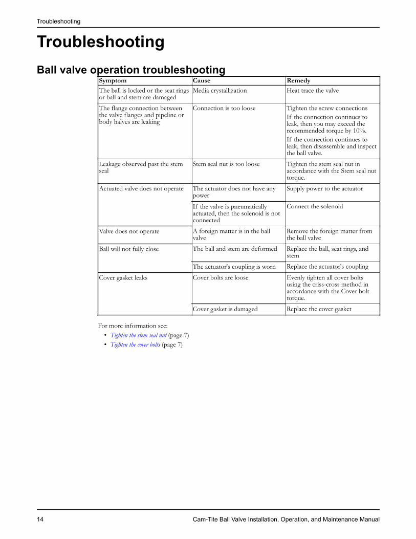
TroubleshootingBall valve operation troubleshooting
Symptom Cause RemedyThe ball is locked or the seat ringsor ball and stem are damaged
Media crystallization Heat trace the valve
The flange connection betweenthe valve flanges and pipeline orbody halves are leaking
Connection is too loose Tighten the screw connectionsIf the connection continues toleak, then you may exceed therecommended torque by 10%.If the connection continues toleak, then disassemble and inspectthe ball valve.
Leakage observed past the stemseal
Stem seal nut is too loose Tighten the stem seal nut inaccordance with the Stem seal nuttorque.
Actuated valve does not operate The actuator does not have anypower
Supply power to the actuator
If the valve is pneumaticallyactuated, then the solenoid is notconnected
Connect the solenoid
Valve does not operate A foreign matter is in the ballvalve
Remove the foreign matter fromthe ball valve
Ball will not fully close The ball and stem are deformed Replace the ball, seat rings, andstem
The actuator's coupling is worn Replace the actuator's coupling
Cover gasket leaks Cover bolts are loose Evenly tighten all cover boltsusing the criss-cross method inaccordance with the Cover bolttorque.
Cover gasket is damaged Replace the cover gasket
For more information see:• Tighten the stem seal nut (page 7)• Tighten the cover bolts (page 7)
Troubleshooting
14 Cam-Tite Ball Valve Installation, Operation, and Maintenance Manual

Parts Listings and Cross-SectionalDrawingsDrawing and parts listExploded view
12
1314
15
1617
1819
2021
2022
23
4
24
25262728
29
724
3
5
6
7
89
1011
1110
4
1 2
Parts listItem Description1 Handle assembly (0.5–2 in. valves)2 Handle (3–6 in. valves)3 Safety ring4 Screw5 Set screw6 Handle hub (3–6 in. valves)
Parts Listings and Cross-Sectional Drawings
Cam-Tite Ball Valve Installation, Operation, and Maintenance Manual 15
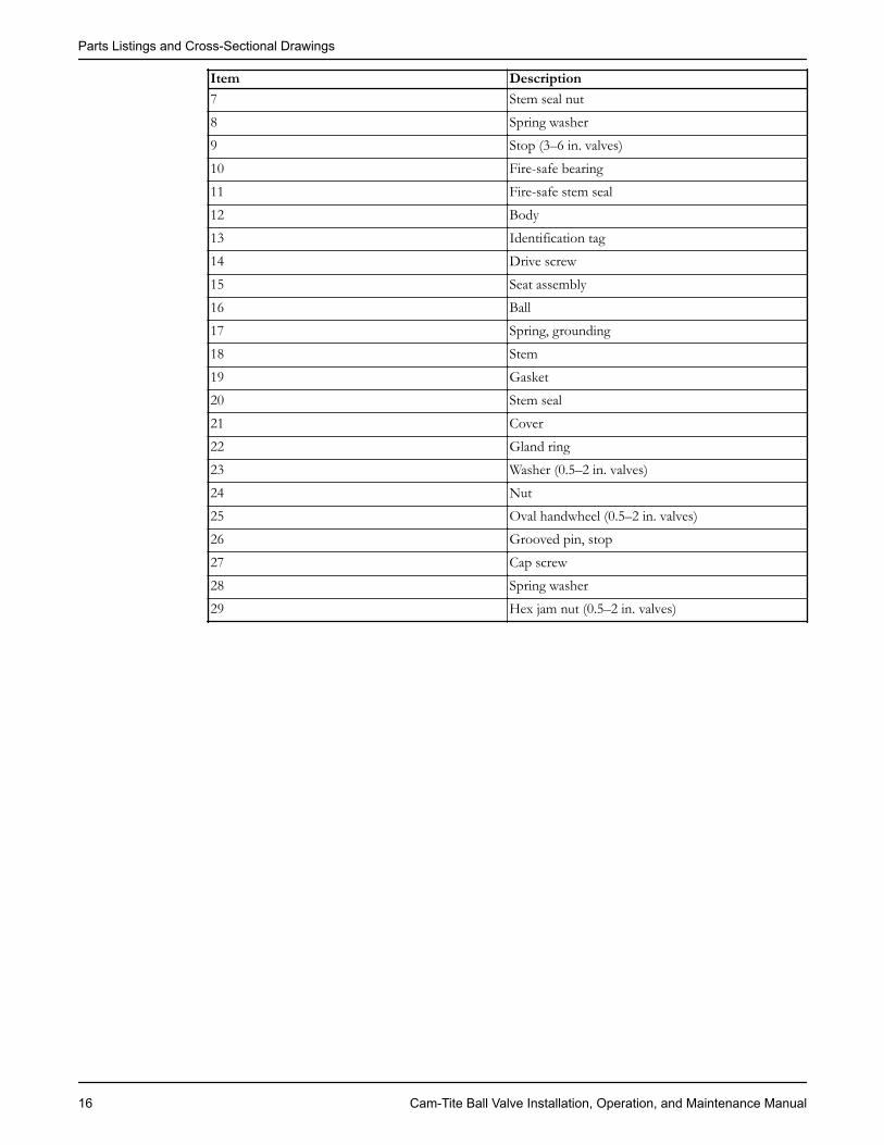
Item Description7 Stem seal nut8 Spring washer9 Stop (3–6 in. valves)10 Fire-safe bearing11 Fire-safe stem seal12 Body13 Identification tag14 Drive screw15 Seat assembly16 Ball17 Spring, grounding18 Stem19 Gasket20 Stem seal21 Cover22 Gland ring23 Washer (0.5–2 in. valves)24 Nut25 Oval handwheel (0.5–2 in. valves)26 Grooved pin, stop27 Cap screw28 Spring washer29 Hex jam nut (0.5–2 in. valves)
Parts Listings and Cross-Sectional Drawings
16 Cam-Tite Ball Valve Installation, Operation, and Maintenance Manual


Visit our Web site for the latest version of this document and more informationhttp://www.engvalves.com
Engineered Valves33 Centerville RoadLancaster, PA 17603USATel. (717) 509–2200Fax (717) 509–2316E-mail: [email protected]
© 2011 ITT Corporation. The original instruction is in English. All non-English instructions are translations of the originalinstruction. CTBV-IOM