Embed Size (px)
Citation preview
BLACK BOX®
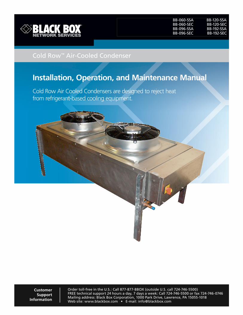
Installation, Operation, and Maintenance Manual
Cold Row Air Cooled Condensers are designed to reject heat from refrigerant-based cooling equipment.
Cold Row™ Air-Cooled Condenser
BB-060-SSA BB-120-SSA BB-060-SEC BB-120-SEC BB-096-SSA BB-192-SSA BB-096-SEC BB-192-SEC
Order toll-free in the U.S.: Call 877-877-BBOX (outside U.S. call 724-746-5500)FREE technical support 24 hours a day, 7 days a week: Call 724-746-5500 or fax 724-746-0746Mailing address: Black Box Corporation, 1000 Park Drive, Lawrence, PA 15055-1018Web site: www.blackbox.com • E-mail: [email protected]
Customer Support
Information
724-746-5500 | blackbox.com Page 2 724-746-5500 | blackbox.com
Trademarks Used in this Manual
We‘re here to help! If you have any questions about your application or our products, contact Black Box Tech Support at 724-746-5500
or go to blackbox.com and click on “Talk to Black Box.”You’ll be live with one of our technical experts in less than 30 seconds.
Trademarks Used in this Manual
Black Box and the Double Diamond logo are registered trademarks, and Cold Row is a trademark, of BB Technologies, Inc.
Teflon is a registered trademark of E. I. du Pont de Nemours and Company.
Any other trademarks mentioned in this manual are acknowledged to be the property of the trademark owners.
724-746-5500 | blackbox.com 724-746-5500 | blackbox.com Page 3
About this Manual
About this Manual
The Cold Row Air-Cooled Condensers fit into the Cold Row DX Base Unit (part number CRDX-A-FS-12KW).
This Cold Row Air-Cooled Condenser Installation, Operation, and Maintenance Manual includes information for the following Black Box part numbers:
• BB-060-SSA
• BB-060-SEC
• BB-096-SSA
• BB-096-SEC
• BB-120-SSA
• BB-120-SEC
• BB-192-SSA
• BB-192-SEC
724-746-5500 | blackbox.com Page 4 724-746-5500 | blackbox.com
FCC and IC RFI Statements
Federal Communications Commission and Industry Canada Radio Frequency Interference Statements
This equipment generates, uses, and can radiate radio-frequency energy, and if not installed and used properly, that is, in strict accordance with the manufacturer’s instructions, may cause inter ference to radio communication. It has been tested and found to comply with the limits for a Class A computing device in accordance with the specifications in Subpart B of Part 15 of FCC rules, which are designed to provide reasonable protection against such interference when the equipment is operated in a commercial environment. Operation of this equipment in a residential area is likely to cause interference, in which case the user at his own expense will be required to take whatever measures may be necessary to correct the interference.
Changes or modifications not expressly approved by the party responsible for compliance could void the user’s authority to operate the equipment.
This digital apparatus does not exceed the Class A limits for radio noise emis sion from digital apparatus set out in the Radio Interference Regulation of Industry Canada.
Le présent appareil numérique n’émet pas de bruits radioélectriques dépassant les limites applicables aux appareils numériques de la classe A prescrites dans le Règlement sur le brouillage radioélectrique publié par Industrie Canada.
724-746-5500 | blackbox.com 724-746-5500 | blackbox.com Page 5
Table of Contents
Table of Contents
1. Introduction ..........................................................................................................................................................7 1.1 General ..........................................................................................................................................................7 1.2 Product Description .....................................................................................................................................................7 1.2.1 Capabilities and Features ................................................................................................................................7 1.2.2 Application Ranges .........................................................................................................................................8 1.2.3 Safety Features ................................................................................................................................................8 1.2.4 General Design ...............................................................................................................................................8 1.2.4.1 Condenser Coil ..................................................................................................................................8 1.2.4.2 Fan Assembly .....................................................................................................................................8 1.2.4.3 Electric Box ........................................................................................................................................8 1.2.4.4 Receiver (Optional) .............................................................................................................................8 1.3 Head Pressure Controls ...............................................................................................................................................9 1.3.1 Variable Condenser Fan Speed ........................................................................................................................9 1.3.2 Flooded Head Pressure Control .......................................................................................................................9 1.4 Product Warranty ...................................................................................................................................................... 11 1.5 Safety ........................................................................................................................................................ 12 1.5.1 General ........................................................................................................................................................ 12 1.5.2 Safety Summary ............................................................................................................................................ 12
2. Installation ........................................................................................................................................................ 15 2.1 Receiving the Equipment ........................................................................................................................................... 15 2.2 Site Preparation ........................................................................................................................................................ 15 2.3 Rigging ........................................................................................................................................................16 2.4 Mounting/Placement................................................................................................................................................. 17 2.4.1 Receiver ........................................................................................................................................................18 2.4.2 Head Pressure Control Valve .........................................................................................................................18 2.5 Refrigerant Piping ......................................................................................................................................................18 2.5.1 Refrigerant Line Sizing ...................................................................................................................................19 2.5.1.1 Discharge Line .................................................................................................................................19 2.5.1.2 Liquid Line .......................................................................................................................................22 2.5.2 Receiver Pipe Installation ...............................................................................................................................23 2.6 Utility Connections ....................................................................................................................................................23 2.6.1 Main Power/Control Wiring ..........................................................................................................................23 2.6.2 Condenser Enable Feature ............................................................................................................................25 2.6.3 Receiver Heater Wiring ..................................................................................................................................25 2.7 System Charging .......................................................................................................................................................25 2.7.1 R410A Refrigerant .........................................................................................................................................25 2.7.2 Estimating Refrigerant Charge ......................................................................................................................26 2.7.3 Preparing System for Charging......................................................................................................................27 2.7.4 Refrigerant Charging Procedures ...................................................................................................................28 2.7.4.1 -20° F Variable Speed Control ..........................................................................................................29 2.7.4.2 -30° F Flooded Head Pressure Control .............................................................................................29 2.7.4.3 Checking the Charge .......................................................................................................................30 2.8 Refrigerant Characteristics .........................................................................................................................................30 2.8.1 Pressure/Temperature Settings ......................................................................................................................30 2.8.2 Saturated Refrigerant Pressure Table .............................................................................................................31

724-746-5500 | blackbox.com Page 6 724-746-5500 | blackbox.com
Table of Contents
3. Start-Up/Commissioning .....................................................................................................................................................32 3.1 Operation ........................................................................................................................................................32 3.2 Step-by-Step Start-Up Instructions ............................................................................................................................32 3.3 Operational Description .............................................................................................................................................32
4. Maintenance/Repairs ........................................................................................................................................................33 4.1 Periodic General Maintenance ...................................................................................................................................33 4.2 Troubleshooting ........................................................................................................................................................33 4.3 Field Service ........................................................................................................................................................34 4.3.1 Leak Detection ..............................................................................................................................................34 4.3.2 Leak Repair ...................................................................................................................................................34 4.3.3 Refrigerant Piping ..........................................................................................................................................34 4.3.4 Electrical System ............................................................................................................................................35
5. Product Support ........................................................................................................................................................36 5.1 Technical Support ......................................................................................................................................................36 5.2 Obtaining Warranty Parts ..........................................................................................................................................36 5.3 Obtaining Spare/Replacement Parts ..........................................................................................................................36
Appendix A: Forms ........................................................................................................................................................38 A.1 Checklist for Completed Installation of Cold Row Air-Cooled Condenser .................................................................38 A.2 Periodic General Maintenance Checks and Services Checklist for Cold Row Air-Cooled Condenser .........................39
Appendix B: Glossary ........................................................................................................................................................40
724-746-5500 | blackbox.com 724-746-5500 | blackbox.com Page 7
Chapter 1: Introduction
1. Introduction
1.1 GeneralThe Cold Row DX is a precision cooling system with the highest-quality craftsmanship using the finest materials available in the industry. The unit will provide years of trouble-free service if installed and maintained in accordance with this manual. Damage to the unit from improper installation, operation, or maintenance is not covered by the warranty.
This manual contains information for installation, operation, maintenance, troubleshooting, and repair. STUDY the instructions contained in this manual. They must be followed to avoid difficulties. Spare parts are available from Black Box to ensure continu-ous operation. Using substitute parts or bypassing electrical or refrigeration components to continue operation is not recommend-ed and will VOID THE WARRANTY. Because of technological advancements, components are subject to change without notice.
Cold Row Air-Cooled Condensers are designed to reject heat from refrigerant-based cooling equipment. They are not intended for use beyond this. Black Box is not liable for any damage resulting from improper use. The unit is designed to be installed outdoors unless otherwise noted on the equipment nameplate.
1.2 Product DescriptionCold Row Air-Cooled Condensers are designed to be the most efficient and reliable condensers in the industry. The unit is an air-cooled, heat-rejection condenser with a vertical air discharge pattern. The unit is self-contained in a lightweight, corrosion-resistant aluminum cabinet designed for mounting to a horizontal surface. The cabinet houses the condenser coil(s) and fan assembly(s). The electrical controls are in an integrally mounted, weatherproof enclosure that is isolated from the rest of the equipment. There are several cabinet sizes based on the capacity of the unit. Refer to the installation drawing supplied with your unit for the layout and dimensions of your cabinet.
The total heat rejection in BTU/Hr. will depend on the unit size, which can range from 12,000 to 242,950 BTU/Hr. Refer to the unit nameplate to identify the model number of your unit. The system will consist of a single circuit. The coil is a closed-loop refrigerant-condensing heat exchanger in which refrigerant is continuously circulated by the pressure differential created by a compressor. The compressor increases refrigerant pressure to a level sufficiently high for it to be cooled and condensed into liquid by the effect of ambient air being drawn over the condenser coil. Cold Row Air-Cooled Condensers are designed to operate with R410A refrigerant.
Variable fan speed control is used for operation in low ambient temperatures down to -20° F. Flooded head pressure control is used with fan cycling for low ambient temperatures down to -30° F.
NOTE: Cold Row Air-Cooled Condensers are strictly for non-residential applications.
Operation of the condenser is independent, controlled by the refrigerant pressure. It can be wired in the field for the system controller (provided with the indoor evaporator section) to enable condenser operation.
1.2.1 Capabilities and Features• All-aluminum cabinet construction.
• Aluminum fin copper tube coil construction.
• Mounting legs.
• Direct driven axial fan(s) equipped with external rotor motors.
• Unit-mounted, weather-resistant control enclosure with lockable service disconnect switch.

724-746-5500 | blackbox.com Page 8 724-746-5500 | blackbox.com
Chapter 1: Introduction
1.2.2 Application RangesCold Row Air-Cooled Condensers are designed for operation within the following ranges:
Outdoor Temperature Range:
Variable Fan Speed Control: -20º F or higher.
Flooded Head Pressure Control: -30º F or higher.
Operating Voltage: VAC input per unit nameplate +/- 10%.
Max. Piping Length; Indoor Evaporator to Condenser: 150 feet equivalent length.
Max. Level Drop; Indoor Evaporator to Condenser: 20 feet (if condenser is below the evaporator).
Storage Conditions: -30º F to +105º F.
NOTE: Damage or malfunction to the unit from storage or operation outside of these ranges will VOID THE WARRANTY.
1.2.3 Safety FeaturesThe condenser is provided with a factory-mounted service disconnect switch as standard. The service disconnect switch electrically isolates the unit during routine maintenance. The handle of the switch may be locked in the “Off” position to prevent unauthorized operation. Finger guard grilles are provided on each fan to protect the operator from injury and to keep large tools or other objects from falling into the fan.
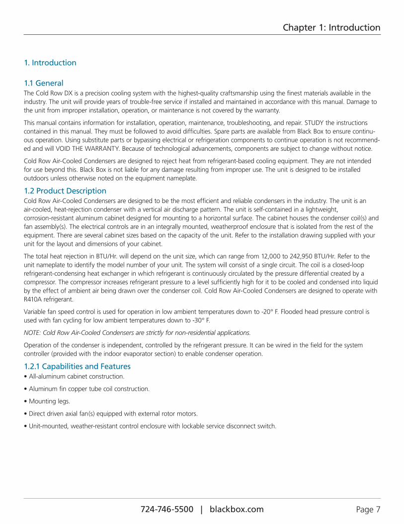
1.2.4 General DesignThe condenser is housed in an aluminum-frame-type cabinet and is rated for outdoor use. Figure 1-1 depicts a typical layout of an air-cooled condenser and identifies the major components.
1.2.4.1 Condenser CoilEach condenser coil is a copper-tube, aluminum-finned coil. The capacity of the condenser, indicated by the unit model number, is based on the rated capacity of the coil.
1.2.4.2 Fan Assembly
For outdoor applications, the condenser is equipped with high efficiency axial type, impeller fan(s). The quantity of fans varies depending upon the capacity of the unit. The fan(s) use corrosion-resistant, multiblade impellers designed for high aerodynamic efficiency, which results in lower power consumption, lower noise levels, and longer life. Each fan uses a direct driven motor with maintenance-free bearings. The fan motors are internally protected from overload.
1.2.4.3 Electric BoxThe electrical components are protected in a weather-resistant enclosure located at the header end of the unit. The electric box has a removable front access panel that is safety interlocked with the service disconnect switch, preventing the panel from being removed when the switch is in the “On” position. The switch must be turned “Off” to gain access to the electrical components.
1.2.4.4 Receiver (Optional)Receivers are furnished for systems using flooded head pressure control for low ambient temperature conditions (see Figure 2-5). The receiver(s) are mounted to an aluminum base frame, which may be attached to a suitable foundation next to the condenser. The receivers are equipped with pressure relief valves and heater pads. A head pressure control valve may be shipped loose for field installation to the receiver if one is not already provided in the indoor A/C unit.
724-746-5500 | blackbox.com 724-746-5500 | blackbox.com Page 9
Chapter 1: Introduction
FAN WITH FINGER GUARD
ELECTRIC BOXSERVICE
DISCONNECT SWITCH
ADJUSTABLE MOUNTING SUPPORT LEG (MUST BE
FULLY EXTENDED)
Figure 1-1. Typical layout: single-circuit condenser.
1.3 Head Pressure Controls1.3.1 Variable Condenser Fan SpeedUsed for outdoor installations where ambient condenser air inlet temperatures may fall to -20° F, a variable-speed condenser fan motor controller is used to maintain head pressure. The fan-speed control is a continual modulation of the motor’s speed. The condenser fan-speed controller monitors the refrigerant discharge pressure and as discharge pressure rises, the fan speed increases. The condenser fan speed varies as required to maintain allowable condenser pressures. The fan-speed controller is set to maintain the correct condensing pressure. See Table 1-1 for the variable fan speed pressure control settings.
When used on systems with multiple condenser fans, variable fan-speed control is used only on the first fan that is closest to the header. Additional fans use pressure fan cycling control to assist the variable-speed fan in maintaining proper head pressure. Fan cycling control turns on the condenser fans as needed to maintain allowable condenser pressures.
Table 1-1. Variable fan speed control settings.
Refrigerant Type1st Fan (Variable)
2nd Fan Range (psig)
R410AMin. Max. Cut-in Cut-out
340 440 460 psig 355 psig
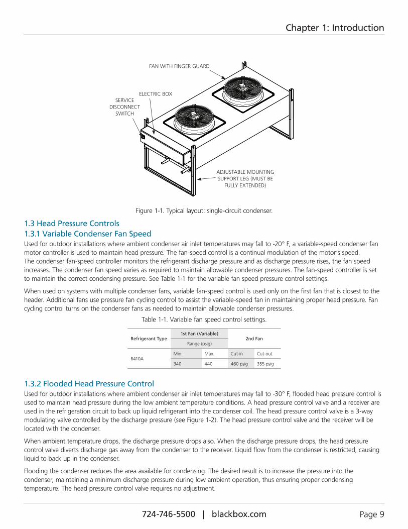
1.3.2 Flooded Head Pressure ControlUsed for outdoor installations where ambient condenser air inlet temperatures may fall to -30° F, flooded head pressure control is used to maintain head pressure during the low ambient temperature conditions. A head pressure control valve and a receiver are used in the refrigeration circuit to back up liquid refrigerant into the condenser coil. The head pressure control valve is a 3-way modulating valve controlled by the discharge pressure (see Figure 1-2). The head pressure control valve and the receiver will be located with the condenser.
When ambient temperature drops, the discharge pressure drops also. When the discharge pressure drops, the head pressure control valve diverts discharge gas away from the condenser to the receiver. Liquid flow from the condenser is restricted, causing liquid to back up in the condenser.
Flooding the condenser reduces the area available for condensing. The desired result is to increase the pressure into the condenser, maintaining a minimum discharge pressure during low ambient operation, thus ensuring proper condensing temperature. The head pressure control valve requires no adjustment.
724-746-5500 | blackbox.com Page 10 724-746-5500 | blackbox.com
Chapter 1: Introduction
This method of controlling head pressure allows the condenser fan to run continuously. While the fan is running, the flooded head pressure control valve modulates the amount of discharge gas entering the receiver. As the pressure increases, the valve diverts more discharge gas to the condenser, allowing more liquid to flow from the condenser to the receiver.
When using this method of head pressure regulation, there must be enough refrigerant in the system to ensure an adequate charge at the lowest expected ambient temperature in which the system will be operating. A receiver is used to store the extra refrigerant when the condenser is not using it.
Figure 1-2. Flooded head-pressure control diagram.
724-746-5500 | blackbox.com 724-746-5500 | blackbox.com Page 11
Chapter 1: Introduction
1.4 Product Warranty12-Month Precision A/C Limited Warranty 24-Month Precision A/C Upgraded Limited Warranty
The 12-Month Precision A/C Limited Warranty applies when Factory-Authorized startup is not purchased at the time of order entry.
The 24-month Precision A/C Upgraded Limited Warranty applies only if Factory-Authorized startup was purchased at the time of Order Entry.
The 12-Month Precision A/C Limited Warranty provided by Black Box Network Services warrants your purchase, including compressors, to be free from defects in material and workmanship. Black Box Network Services’ obligation under this warranty is to repair or replace, at its option, any part or parts which are determined by Black Box Network Services to be defective for a period of 12 months from the date of shipment when an accurately completed Precision Cooling Limited Warranty Registration and Startup Checklist Form has been submitted to Black Box Network Services, within 90 days from shipment. Parts repaired or replaced under this warranty are shipped FOB Factory, and warranted for the balance of the original warranty period or for 90 days from the date of installation, whichever is greater. If the factory startup form is not returned to Black Box Network Services within 90 days from the date of equipment shipment, the equipment warranty will be terminated on the 91st day from shipment. This limited warranty does not include labor, freon, or any other expense required to replace the defective component and bring the unit back to a working status.
The 24-Month Precision A/C, Upgraded Limited Warranty provided by Black Box Network Services warrants your purchase, including compressors, to be free from defects in material and workmanship for 24 months. Black Box Network Services’ obligation under this warranty is to repair or replace, at its option, any part or parts which are determined by Black Box Network Services to be defective for a period of 24 months from the date of startup. This warranty also includes labor needed to perform any warranty work for a period of 90 days from the date of startup. Parts repaired or replaced under this warranty are shipped FOB factory ground, and warranted for the balance of the original warranty period or for 90 days from the date of installation, whichever is greater. If the factory is not allowed to start the equipment within 90 days from the date of shipment, the warranty will commence on the 91st day from equipment shipment. This limited warranty does not include labor, freon, or any other expense required to replace the defective component and bring the unit back to a working status.
In the event equipment is shipped to Black Box for temporary storage for 6 months or less, warranty begins and startup checklist is required to be on file with Black Box Network Services field service within 90 days of shipment to job site for installation.
Black Box Network Services’ warranty does not cover failures caused by improper installation, abuse, misuse, alteration, misapplication, improper or lack of maintenance, negligence, accident, normal deterioration (including wear and tear), or the use of improper parts or improper repair.
Purchaser’s remedies are limited to replacement or repair of non-conforming materials in accordance with the written warranty.This warranty does not include costs for transportation, travel expenses, costs for removal or reinstallation of equipment or labor for repairs (*except as set forth above) or replacements made in the field.
If any sample was shown to the buyer, such sample was merely to illustrate the general type and quality of the product, and not to represent that the equipment would necessarily conform to the sample.
This is the only warranty given by the seller, and such warranty is only given to the buyer for commercial or industrial purposes.The warranty is not enforceable until the invoice(s) is paid in full.
THIS FOREGOING SHALL CONSTITUTE BLACK BOX NETWORK SERVICES’ ENTIRE LIABILITY AND YOUR EXCLUSIVE REMEDY. IN NO EVENT SHALL BLACK BOX NETWORK SERVICES BE LIABLE FOR ANY DEFECT, INDIRECT, SPECIAL, INCIDENTAL, CONSEQUENTIAL, OR EXEMPLARY DAMAGES, INCLUDING LOST PROFITS (EVEN IF ADVISED OF THE POSSIBILITY THEREOF) ARISING IN ANY WAY OUT OF THE INSTALLATION, USE, OR MAINTENANCE OF THE EQUIPMENT. THIS WARRANTY IS IN LIEU OF ALL OTHER WARRANTIES, EXPRESSED OR IMPLIED, INCLUDING WARRANTIES OF MERCHANTABILITY OR FITNESS FOR A PARTICULAR PURPOSE.
This warranty supersedes all other previously printed warranties dated prior to this document in regards to Diagnostic Labor Warranty.

724-746-5500 | blackbox.com Page 12 724-746-5500 | blackbox.com
Chapter 1: Introduction
1.5 Safety
1.5.1 GeneralBlack Box uses NOTES along with CAUTION and WARNING symbols throughout this manual to draw your attention to important operational and safety information.
A bold text NOTE marks a short message in the information to alert you to an important detail.
A bold text CAUTION safety alert appears with information that is important for protecting your equipment and performance. Be especially careful to read and follow all cautions that apply to your application.
A bold text WARNING safety alert appears with information that is important for protecting you from harm and the equipment from damage. Pay very close attention to all warnings that apply to your application.
A safety alert symbol accompanies a general WARNING or CAUTION safety statement.
A safety alert symbol accompanies an electrical shock hazard WARNING or CAUTION safety statement.
1.5.2 Safety SummaryThe following statements are general guidelines followed by warnings and cautions applicable throughout the manual.
Prior to performing any installation, operation, maintenance or troubleshooting procedure read and understand all instructions, recommendations and guidelines contained within this manual.
CAUTION
All maintenance and/or repairs must be performed by a journeyman refrigeration mechanic or air-conditioning technician.
CAUTION
Never lift any component in excess of 35 pounds without help. If a lifting device is used to move a unit, ensure it is capable of supporting the unit.
CAUTION
Do not allow the unit to swing while suspended from a lifting device. Failure to observe this warning may result in injury to personnel and damage to the equipment.
CAUTION
Do not allow anyone under the equipment suspended from a lifting sling.
WARNING
High voltage is used in the operation of this equipment. Death on contact may result if personnel fail to observe safety precautions.
CAUTION
When working on electrical equipment, remove all jewelry, watches, rings, etc. Keep one hand away from the equipment to reduce the hazard of current flowing through vital organs of the body.
CAUTION
Always disconnect the main power supply to the equipment at the main power disconnect switch before beginning work on the equipment. A lock-out tag-out procedure should be followed to ensure that power is not inadvertently reconnected.
724-746-5500 | blackbox.com 724-746-5500 | blackbox.com Page 13
Chapter 1: Introduction
WARNING
Equipment may contain components subject to electrostatic discharge (ESD). Before attempting to mount or service these electronic devices, ensure you have no charge built up by touching a ground source. When possible, use a wrist-grounding strap when working on or near electronic devices.
CAUTION
Never work on electrical equipment unless another person who is familiar with the operation and hazards of the equipment and competent in administering first aid is nearby.
CAUTION
All personnel working on or near equipment should be familiar with hazards associated with electrical maintenance. Safety placards/stickers have been placed on the unit to call attention to all personal and equipment damage hazard areas.
CAUTION
Ensure the unit is properly phased. Improper phasing can cause severe damage to the compressor.
WARNING
Refrigerant (R410A) is used with this equipment. Death or serious injury may result if personnel fail to observe proper safety precautions. Great care must be exercised to prevent contact of liquid refrigerant or refrigerant gas, discharged under pressure, with any part of the body. The extremely low temperature resulting from the rapid expansion of liquid refrigerant or pressurized gas can cause sudden and irreversible tissue damage.
As a minimum, all personnel should wear thermal protective gloves and face-shield/goggles when working with refrigerant. Application of excessive heat to any component will cause extreme pressure and may result in a rupture.
Exposure of refrigerant to an open flame or a very hot surface will cause a chemical reaction that will form carbonyl chloride (hydrochloric/hydrofluoric acid); a highly poisonous and corrosive gas commonly referred to as PHOSGENE. In its natural state, refrigerant is a colorless, odorless vapor with no toxic characteristics. It is heavier than air and will disperse rapidly in a well-ventilated area. In an unventilated area, it presents a danger as a suffocant.
Always refer to the manufacturer’s Material Safety Data Sheet (MSDS) provided with the unit.
WARNING
Avoid skin contact or inhaling fumes from any acid formed by burnout of oil and refrigerant. Wear gas mask if area is not thoroughly ventilated. Wear protective goggles or glasses to protect eyes. Wear rubber gloves to protect hands. Use care to avoid spilling compressor burnout sludge. If sludge is spilled, clean area thoroughly.
WARNING
When performing soldering or de-soldering operations, make certain the refrigeration system is fully recovered and purged and dry nitrogen is flowing through the system at the rate of not less than 1-2 CFM (.03–.06 m3/minute).
724-746-5500 | blackbox.com Page 14 724-746-5500 | blackbox.com
Chapter 1: Introduction
CAUTION
Certain maintenance or cleaning procedures may call for the use and handling of chemicals, solvents, or cleansers. Always refer to the manufacturer’s MSDS prior to using these materials. Clean parts in a well-ventilated area. Avoid inhalation of solvent fumes and prolonged exposure of skin to cleaning solvents. Wash exposed skin thoroughly after contact with solvents.
CAUTION
Do not use cleaning solvents near open flame or excessive heat. Wear eye protection when blowing solvent from parts. The pressure-wash should not exceed 30 psig. Solvent solutions should be disposed of in accordance with local and state regulatory statutes.
724-746-5500 | blackbox.com 724-746-5500 | blackbox.com Page 15
Chapter 2: Installation
2. Installation
2.1 Receiving the EquipmentYour system has been tested and inspected prior to shipment. To ensure that your equipment is received in excellent condition, make a visual inspection of the equipment immediately upon delivery. Carefully remove the shipping container and all protective packaging. Open the box and thoroughly inspect the unit for any signs of transit-incurred damage. If there is shipping damage, it must be noted on the freight carrier’s delivery forms BEFORE signing for the equipment. Any freight claims MUST be done through the freight carrier. Black Box ships all equipment FOB factory and is not liable for any equipment damage while in transit. Black Box can assist in the claim filing process with the freight carrier. If any damage is present, notify Black Box Technical Support at 724-746-5500 or [email protected] prior to attempting any repairs. Refer to Chapter 5 of this manual for instructions.
Check the equipment against the packing slip to see if the shipment is complete. Report any discrepancies to the appropriate authority.
A Data Package has been sent with your unit. It contains this manual, system drawings, applicable MSDSs, and other appropriate instructions based on the configuration of your unit and options selected. The data package has been shipped with your unit in a clear plastic bag. These documents need to be kept with the unit for future reference.
2.2 Site PreparationCold Row Air-Cooled Condensers are designed with easy service access in mind. Install the condenser in a secure location where it cannot be tampered with and the main power disconnect switch cannot be inadvertently turned “Off.” Allow access to the unit for routine operation, servicing, and for necessary maintenance. The components on outdoor condensers are accessed through the top by removing the fan assembly panel. The electric box is accessed at the header end of the unit. Locate the unit where the fan(s) are not likely to draw dirt and debris into the coil fins. Refer to the installation drawing provided with your unit for the dimensions.
NOTE: Working clearance requirements need to be established prior to mounting the unit. Refer to local and national electrical codes.
CAUTION
The condenser must be kept level to operate properly.
724-746-5500 | blackbox.com Page 16 724-746-5500 | blackbox.com
Chapter 2: Installation
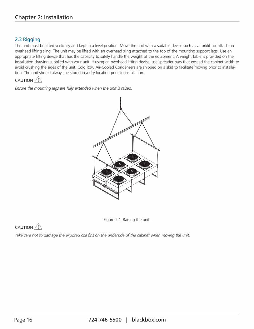
2.3 RiggingThe unit must be lifted vertically and kept in a level position. Move the unit with a suitable device such as a forklift or attach an overhead lifting sling. The unit may be lifted with an overhead sling attached to the top of the mounting support legs. Use an appropriate lifting device that has the capacity to safely handle the weight of the equipment. A weight table is provided on the installation drawing supplied with your unit. If using an overhead lifting device, use spreader bars that exceed the cabinet width to avoid crushing the sides of the unit. Cold Row Air-Cooled Condensers are shipped on a skid to facilitate moving prior to installa-tion. The unit should always be stored in a dry location prior to installation.
CAUTION
Ensure the mounting legs are fully extended when the unit is raised.
Figure 2-1. Raising the unit.
CAUTION
Take care not to damage the exposed coil fins on the underside of the cabinet when moving the unit.
724-746-5500 | blackbox.com 724-746-5500 | blackbox.com Page 17
Chapter 2: Installation
2.4 Mounting/PlacementCold Row Air-Cooled Condensers are designed for mounting to a flat surface outdoors. Condenser(s) must not be located in the vicinity of steam, hot air, or fume exhausts. Avoid overhead obstructions. Ensure the unit is not located above or near noise sensitive areas. If possible, make use of terrain features such as trees and buildings to provide a shaded location. This will minimize the solar load on the unit. Avoid ground-level sites that are accessible to the public.
Ensure the mounting location is capable of supporting the weight of the equipment. Refer to the installation drawing for the non-charged system weight. When installing the unit on a roof, ensure the weight is adequately distributed to the load-bearing points. For ground-mounted units, install a concrete slab as shown in Figure 4. The slab should extend below the frost line and be at least 2 inches higher than the surrounding grade. The slab should extend at least 2" beyond the outer profile of the condenser on all sides.
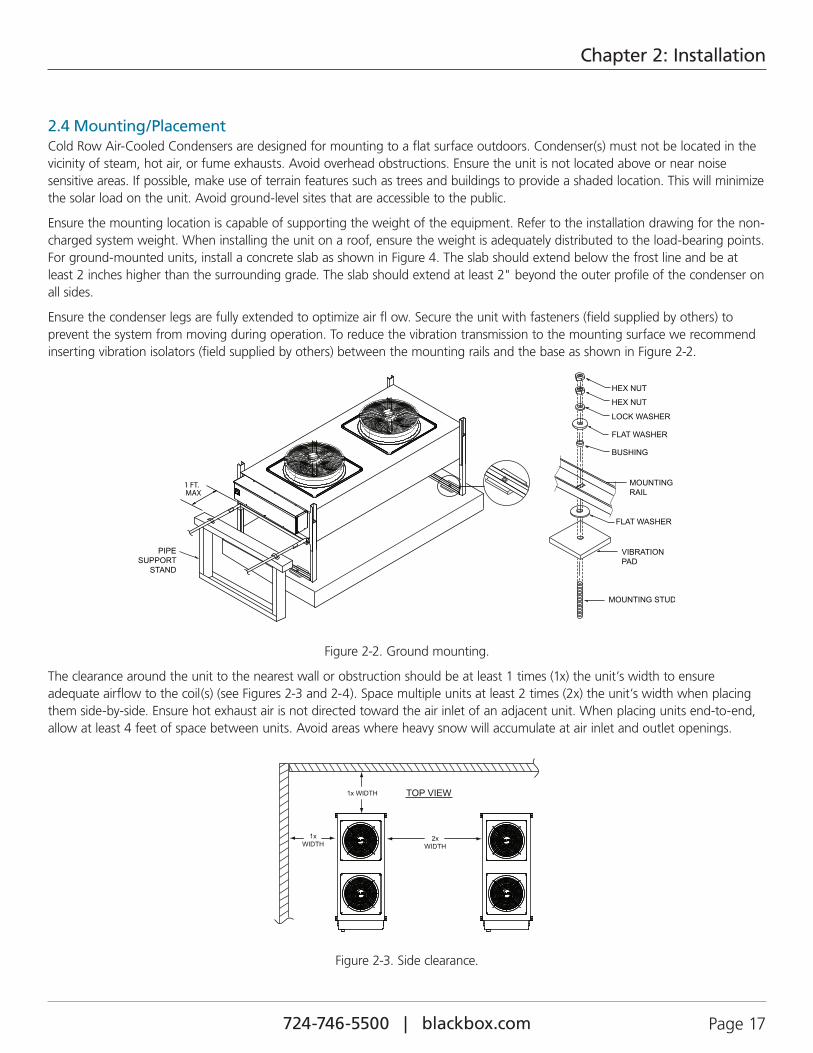
Ensure the condenser legs are fully extended to optimize air fl ow. Secure the unit with fasteners (field supplied by others) to prevent the system from moving during operation. To reduce the vibration transmission to the mounting surface we recommend inserting vibration isolators (field supplied by others) between the mounting rails and the base as shown in Figure 2-2.
Figure 2-2. Ground mounting.
The clearance around the unit to the nearest wall or obstruction should be at least 1 times (1x) the unit’s width to ensure adequate airflow to the coil(s) (see Figures 2-3 and 2-4). Space multiple units at least 2 times (2x) the unit’s width when placing them side-by-side. Ensure hot exhaust air is not directed toward the air inlet of an adjacent unit. When placing units end-to-end, allow at least 4 feet of space between units. Avoid areas where heavy snow will accumulate at air inlet and outlet openings.
Figure 2-3. Side clearance.
724-746-5500 | blackbox.com Page 18 724-746-5500 | blackbox.com
Chapter 2: Installation
If the unit(s) are surrounded by three walls or if they are located in a pit, space them at least 2 times (2x) the unit’s width from the nearest walls (see Figure 2-4). The top of the unit must be equal to the height of the walls or the pit. A stack may be used, if necessary, to extend the air discharge. The height of the extension must not exceed 10 feet.
Figure 2-4. Walled areas or pits.
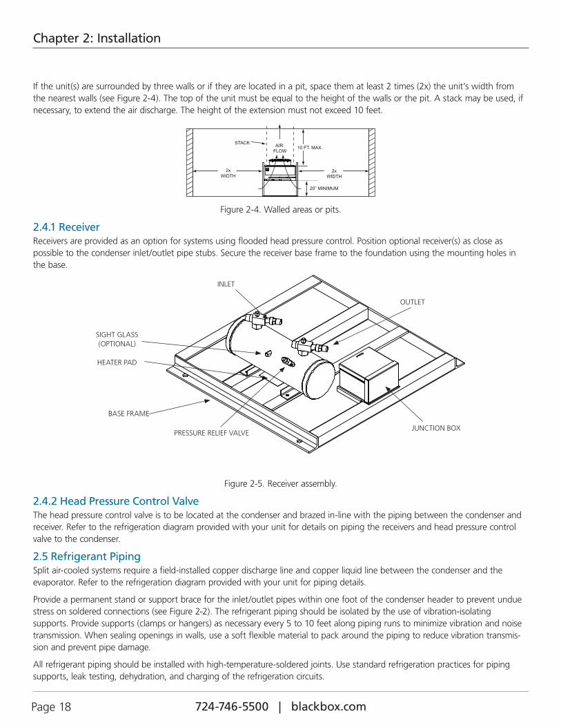
2.4.1 ReceiverReceivers are provided as an option for systems using flooded head pressure control. Position optional receiver(s) as close as possible to the condenser inlet/outlet pipe stubs. Secure the receiver base frame to the foundation using the mounting holes in the base.
SIGHT GLASS (OPTIONAL)
HEATER PAD
BASE FRAME
PRESSURE RELIEF VALVE
OUTLET
INLET
JUNCTION BOX
Figure 2-5. Receiver assembly.
2.4.2 Head Pressure Control ValveThe head pressure control valve is to be located at the condenser and brazed in-line with the piping between the condenser and receiver. Refer to the refrigeration diagram provided with your unit for details on piping the receivers and head pressure control valve to the condenser.
2.5 Refrigerant PipingSplit air-cooled systems require a field-installed copper discharge line and copper liquid line between the condenser and the evaporator. Refer to the refrigeration diagram provided with your unit for piping details.
Provide a permanent stand or support brace for the inlet/outlet pipes within one foot of the condenser header to prevent undue stress on soldered connections (see Figure 2-2). The refrigerant piping should be isolated by the use of vibration-isolating supports. Provide supports (clamps or hangers) as necessary every 5 to 10 feet along piping runs to minimize vibration and noise transmission. When sealing openings in walls, use a soft flexible material to pack around the piping to reduce vibration transmis-sion and prevent pipe damage.
All refrigerant piping should be installed with high-temperature-soldered joints. Use standard refrigeration practices for piping supports, leak testing, dehydration, and charging of the refrigeration circuits.

724-746-5500 | blackbox.com 724-746-5500 | blackbox.com Page 19
Chapter 2: Installation
NOTE: Refer to the Copeland Applications Data Guide for more detailed information regarding installation of refrigerant piping.
The condenser is shipped with a dry nitrogen holding charge that must be removed before piping and charging the system. Clear all pipe connections of debris and prepare the connections for soldering. Use only “L” or “K” grade refrigerant copper tubing. Be careful not to allow solder/piping debris to get inside refrigerant lines. Silver solder containing a minimum of 15% silver is recommended.
Dry nitrogen should be flowing through the tubing while soldering at a rate of not less than 1-2 CFM (.03–.06 m3/minute). When performing soldering or brazing, wrap wet rags around the pipes and the nearby refrigeration components (such as the optional head pressure control valve) to keep excessive heat from traveling through the pipe and damaging the internal parts of the components.
2.5.1 Refrigerant Line SizingThe following general guidelines may be used to assist in determining the size of the refrigerant lines between the evaporator section and the remote air-cooled condenser.
IMPORTANT NOTE: Refrigerant piping between the indoor evaporator and condenser must not exceed 150 feet (total equivalent length). The maximum level drop from the indoor evaporator to the condenser must not exceed 20 feet.
Refrigerant lines for split systems must be sized according to the piping distance between the evaporator and the condenser with consideration for elevation changes. Each valve, fitting and bend in the refrigerant line must also be considered in this calculation. Refer to Table 2-1 for standard equivalent lengths of straight pipe.
Table 2-1. Equivalent length (ft.) of straight pipe.
OD (in.) Line Size Globe Valve Angle Valve 90° Elbow 45° Elbox Tee Line Tee Branch
1⁄2" 9.0 5.0 0.9 0.4 0.6 2.0
5⁄8" 12 6.0 1.0 0.5 0.8 2.5
7⁄8" 15 8.0 1.5 0.7 1.0 3.5
11⁄8" 22 12 1.8 0.9 1.5 4.5
13⁄8" 28 15 2.4 1.2 1.8 6.0
15⁄8" 35 17 2.8 1.4 2.0 7.0
21⁄8" 45 22 3.9 1.8 3.0 10
Refer to the installation manual provided with the A/C system for tables showing the recommended liquid line and discharge line sizes for the A/C system you are installing.
When sizing refrigerant piping, consider the varying BTU capacities of indoor evaporators and the equivalent length of pipe need-ed between the remote condenser and the evaporator.
If the pressure drop is too high, the capacity of the compressor decreases and the power required increases. An excessive refriger-ant charge will be applied if the volume of the piping is too large.
Refrigerant line sizing for discharge and liquid lines should create no more than a 2 to 3° F pressure drop (1° F = 4.75 psi).
NOTE: The size of the condenser pipe connections does not indicate the size of the refrigerant lines to be used. In cases where the pipe size doesn’t match the size of the connection, reducing fittings must be used to transition between the connection and the pipe.
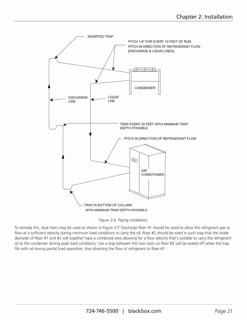
2.5.1.1 Discharge LineSince refrigerant may condense during “Off” cycles, all vertical discharge risers should be designed to prevent liquid refrigerant from flowing back into the compressor. If the condenser is installed above the evaporator, the discharge line should include a shallow P-trap at the lowest point in the piping (see Figure 2-6).
724-746-5500 | blackbox.com Page 20 724-746-5500 | blackbox.com
Chapter 2: Installation
The highest point in the discharge line should be above the condenser coil. Install an inverted trap at the condenser inlet to prevent liquid refrigerant from flowing backwards into the hot gas riser during “off” cycles. Additionally, shallow P-traps must be included in the discharge line for every 20 feet of vertical rise. All horizontal refrigerant lines should be pitched in the direction of flow at least 1⁄4" per 10 feet.
Discharge line velocities must be a minimum of 500 fpm for horizontal runs and 1000 fpm for vertical risers to ensure oil is returned to the compressor at both full and partial load operating conditions. It’s important that the discharge line is sized with a certain degree of pressure drop. This will ensure the refrigerant flows at a velocity high enough for the refrigerant vapor to carry the oil with it to the condenser and to prevent the oil from returning to the compressor.
Compressor discharge pressure is always higher than condensing pressure because of the line pressure drop. The line pressure drop also causes a change in the refrigerant saturation temperature. The discharge line needs to be sized so the pressure drop doesn’t cause a corresponding change in saturation temperature exceeding 2° F.
Discharge piping is typically sized for a total line pressure drop of 5 psi (+/- 50%), which results in only a 1⁄2 to 1% reduction in compressor capacity. Pressure drops greater than 10 psi will impair system performance.
Figure 2-6 depicts a typical piping diagram when the condenser is located at a higher level than the indoor evaporator. In this situ-ation, it’s especially important to size the discharge line properly. If the discharge line is sized correctly for full load operation, the gas velocity may be too low during minimum load conditions to carry the refrigerant oil vertically through the discharge line to the condenser coil. Decreasing the size of the discharge line will increase the refrigerant velocity, however, it will also restrict the flow of refrigerant at full load conditions, creating an excessive refrigerant pressure drop.
724-746-5500 | blackbox.com 724-746-5500 | blackbox.com Page 21
Chapter 2: Installation
Figure 2-6. Piping installation.
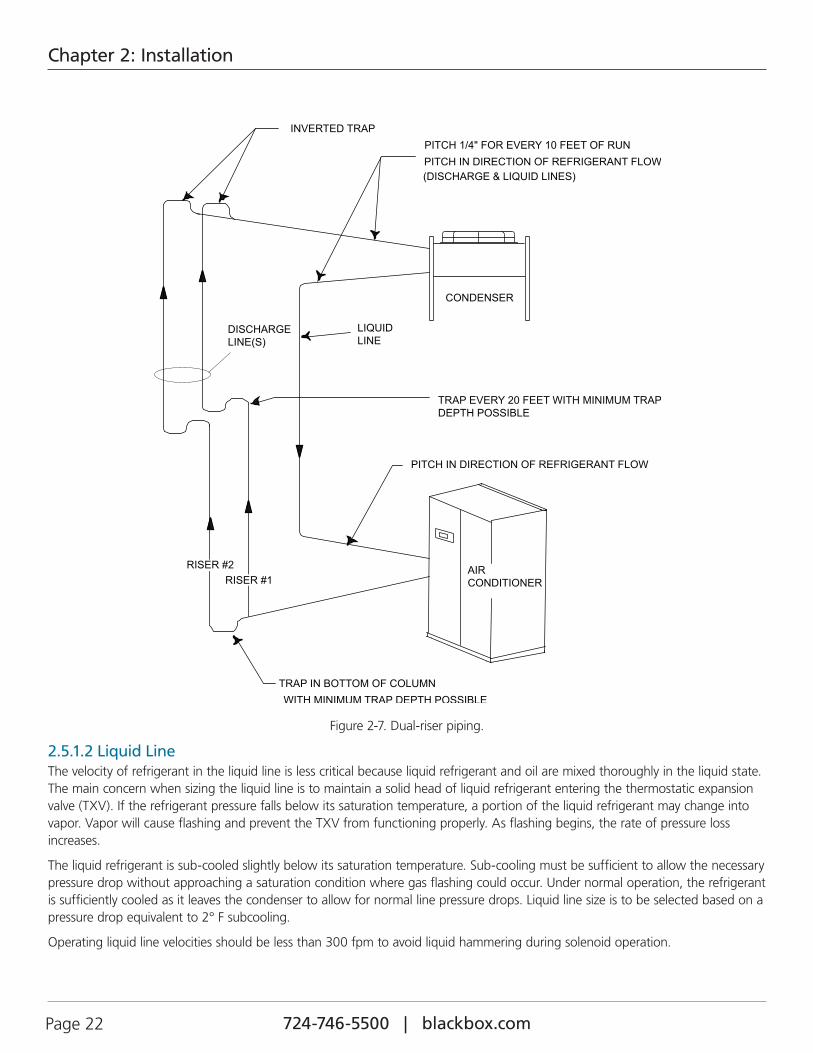
To remedy this, dual risers may be used as shown in Figure 2-7. Discharge Riser #1 should be sized to allow the refrigerant gas to flow at a sufficient velocity during minimum load conditions to carry the oil. Riser #2 should be sized in such way that the inside diameter of Riser #1 and #2 will together have a combined area allowing for a flow velocity that’s suitable to carry the refrigerant oil to the condenser during peak load conditions. Use a trap between the two risers so Riser #2 will be sealed off when the trap fills with oil during partial load operation, thus diverting the flow of refrigerant to Riser #1.
724-746-5500 | blackbox.com Page 22 724-746-5500 | blackbox.com
Chapter 2: Installation
Figure 2-7. Dual-riser piping.
2.5.1.2 Liquid LineThe velocity of refrigerant in the liquid line is less critical because liquid refrigerant and oil are mixed thoroughly in the liquid state. The main concern when sizing the liquid line is to maintain a solid head of liquid refrigerant entering the thermostatic expansion valve (TXV). If the refrigerant pressure falls below its saturation temperature, a portion of the liquid refrigerant may change into vapor. Vapor will cause flashing and prevent the TXV from functioning properly. As flashing begins, the rate of pressure loss increases.
The liquid refrigerant is sub-cooled slightly below its saturation temperature. Sub-cooling must be sufficient to allow the necessary pressure drop without approaching a saturation condition where gas flashing could occur. Under normal operation, the refrigerant is sufficiently cooled as it leaves the condenser to allow for normal line pressure drops. Liquid line size is to be selected based on a pressure drop equivalent to 2° F subcooling.
Operating liquid line velocities should be less than 300 fpm to avoid liquid hammering during solenoid operation.
724-746-5500 | blackbox.com 724-746-5500 | blackbox.com Page 23
Chapter 2: Installation
If the condenser is installed below the evaporator section, the installer must observe the pressure changes that occur as a result of the elevation change. See Table 2-2 for the vertical pressure drops for the refrigerant used.
Table 2-2. Vertical pressure drop for refrigerant.
Refrigerant TypePressure drop in PSI/ft. (risers)
R410A 0.43
NOTE: When a receiver is used with the equipment, it should be below the level of the condenser. The liquid line from the condenser to the receiver should be liberally sized to allow the refrigerant to freely flow from the condenser to the receiver. The total refrigerant line pressure drop must not exceed 14 psig across the condenser and the interconnecting piping to the evaporator and condenser sections.
2.5.2 Receiver Pipe InstallationReceiver inlets and outlets are equipped with rotolock valves, which must have brazed-pipe connections. It is important to remove the valve from the adapter on the receiver before brazing the refrigerant piping to it. Wrap wet rags around the valve body to prevent the internal parts from being damaged by the heat.
After brazing the pipe to the valve, remove and replace the Teflon® o-ring in the rotolock adapter with the new one that is cable-tied to the valve. When re-attaching the valve to the receiver, apply thread lock to the adapter threads to prevent it from vibrating loose. Tighten the valve to the receiver and check it for leaks when performing the Preparing System for Charging steps (Section 2.7.3).
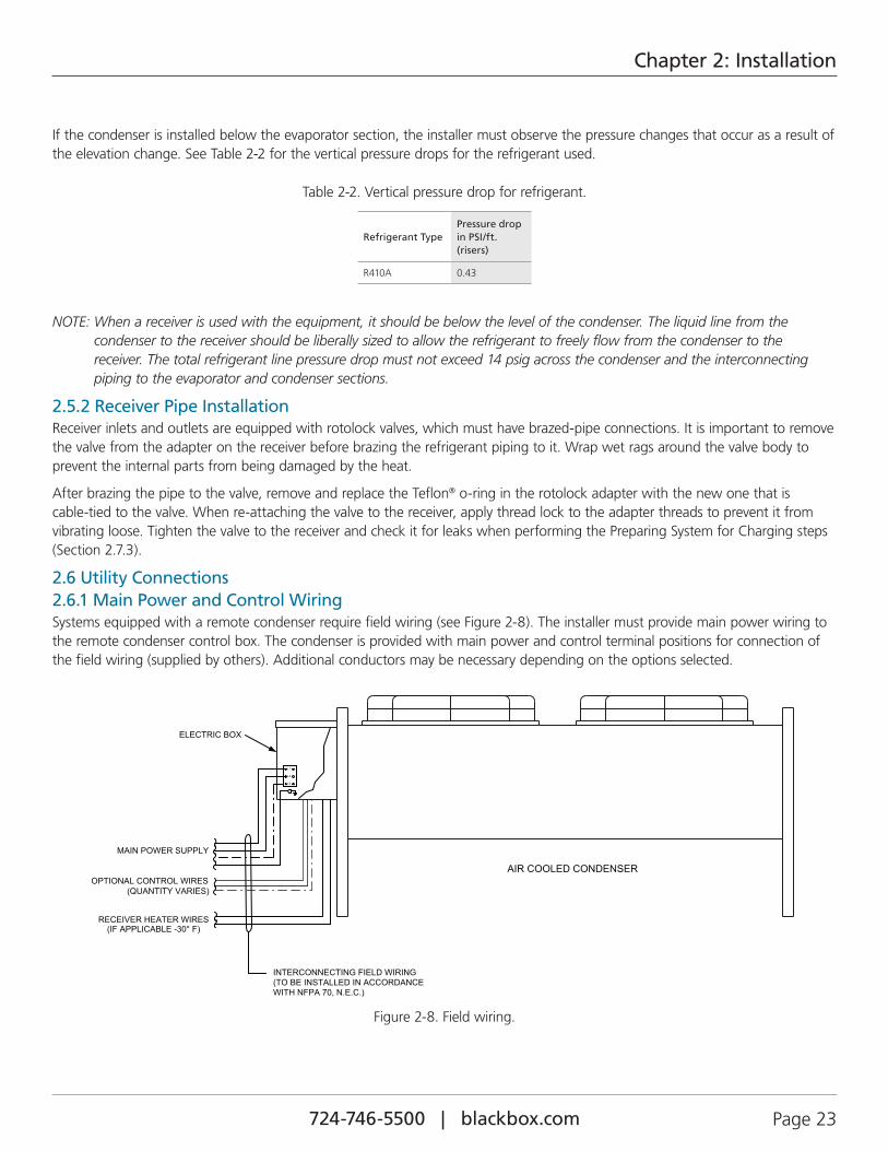
2.6 Utility Connections2.6.1 Main Power and Control WiringSystems equipped with a remote condenser require field wiring (see Figure 2-8). The installer must provide main power wiring to the remote condenser control box. The condenser is provided with main power and control terminal positions for connection of the field wiring (supplied by others). Additional conductors may be necessary depending on the options selected.
Figure 2-8. Field wiring.

724-746-5500 | blackbox.com Page 24 724-746-5500 | blackbox.com
Chapter 2: Installation
Verify that the main power supply coincides with the voltage, phase and frequency information specified on the system name-plate (see Figure 2-9). The supply voltage measured at the unit must be within ±10% of the voltage specified on the nameplate. The nameplate also provides the full load amps (FLA), the current that the unit will draw under full design load, the minimum cir-cuit ampacity (MCA) for wire sizing, and the maximum fuse or HACR (Heating, Air Conditioning, Refrigeration) breaker size (MAX FUSE/CKT BKR) for circuit protection. The unit’s nameplate is located inside the electrical box.
Figure 2-9. Sample nameplate.
Pilot holes or electrical knock-outs for the conduit are located in the bottom of the electric box. A label stating “MAIN POWER INPUT” is nearby. The main power wires are terminated at the line side of the service disconnect switch located within the electric box. A separate equipment ground lug is provided within the electrical box for termination of the ground wire.
WARNING
High voltage is used in the operation of this equipment. Death on contact may result if personnel fail to observe safety precautions.
724-746-5500 | blackbox.com 724-746-5500 | blackbox.com Page 25
Chapter 2: Installation
WARNING
Verify power is turned off before making connections to the equipment.
NOTE: All wiring must conform to local and national electrical code requirements. Use of copper conductors only is required. Wiring terminations may become loose during transit of the equipment; therefore, you must verify that all wiring terminations are secure.
It is important to note that the control transformer supplied with the equipment is sized and selected based upon the expected load for the system.
CAUTION
Do not connect any additional loads to the system control transformer. Connecting additional loads to the factory-supplied control transformer may result in overloading of the transformer.
CAUTION
Improper wire connections will result in the reverse rotation of the fan. To correct this problem, exchange any two of the incoming main power wires at the main power circuit breaker. Do NOT rewire the unit’s individual components.
Identify the options that were purchased with your system to confirm which field connections are required. The number of control conductors needed will vary depending on the options and type of control method being used. Refer to the electrical drawing supplied with your unit to determine the total number of interconnecting conductors required for your equipment and for the proper wire terminations.
2.6.2 Condenser Enable FeatureAs an option, the installer may wire a 2-conductor control cable between the A/C system and the condenser so the system con-troller may enable the condenser to operate only when the compressor is running. You must remove the jumper (X2:1-X2:2) from the remote condenser terminal board (see the wiring diagram that ships with the condenser). Wire 24-VAC control conductors from the terminal board within the A/C unit to the remote condenser terminal board. If control wires aren’t installed (and the jumper remains in place), the condenser is always enabled and will turn on and off based on the condenser’s pressure control switch setting(s).
The condenser enable feature may be used in high ambient temperature locations to prevent the condenser from running unnecessarily. In some cases, outdoor temperature conditions may raise refrigerant line pressures high enough to cause the condenser fans to start operating even if the compressor isn’t on.
2.6.3 Receiver Heater WiringIf receiver(s) are used, it will be necessary to provide a 2-conductor cable for the heating pad(s). Connect the wires from the terminals inside the junction box on the receiver base (see Figure 2-5) to the terminal block in the condenser electric box. Drill an entrance hole in the condenser electric box or use an available knock-out if furnished. See the condenser’s wiring diagram for the correct wire terminal positions.
2.7 System ChargingTables 2-3 and 2-4 show the temperature/pressure characteristics for R410A.
2.7.1 R410A RefrigerantR410A is a refrigerant recognized for being safer for the environment than some other refrigerants. This refrigerant contains no chlorine, the component in HCFC’s that destroy the earth’s ozone layer. However, take care to prevent leakage because R410A can contribute to the greenhouse effect if released. If the refrigerant gas is released in an enclosed space, it can become a suffocant.
Refrigerant R410A is a blended refrigerant that consists of component parts, however, the component parts of R410A refrigerant have the same composition at various operating temperature/pressures in the liquid phase and gas phase, reducing the temperature glide effect.
724-746-5500 | blackbox.com Page 26 724-746-5500 | blackbox.com
Chapter 2: Installation
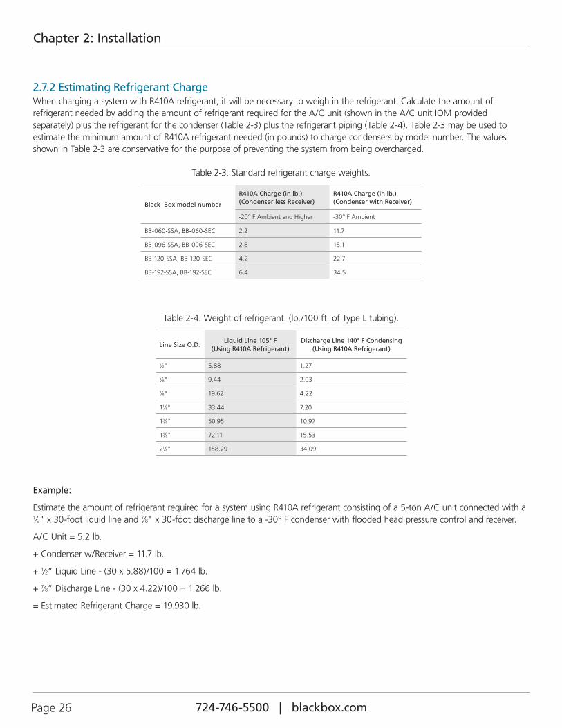
2.7.2 Estimating Refrigerant ChargeWhen charging a system with R410A refrigerant, it will be necessary to weigh in the refrigerant. Calculate the amount of refrigerant needed by adding the amount of refrigerant required for the A/C unit (shown in the A/C unit IOM provided separately) plus the refrigerant for the condenser (Table 2-3) plus the refrigerant piping (Table 2-4). Table 2-3 may be used to estimate the minimum amount of R410A refrigerant needed (in pounds) to charge condensers by model number. The values shown in Table 2-3 are conservative for the purpose of preventing the system from being overcharged.
Table 2-3. Standard refrigerant charge weights.
Black Box model number
R410A Charge (in lb.) (Condenser less Receiver)
R410A Charge (in lb.) (Condenser with Receiver)
-20° F Ambient and Higher -30° F Ambient
BB-060-SSA, BB-060-SEC 2.2 11.7
BB-096-SSA, BB-096-SEC 2.8 15.1
BB-120-SSA, BB-120-SEC 4.2 22.7
BB-192-SSA, BB-192-SEC 6.4 34.5
Table 2-4. Weight of refrigerant. (lb./100 ft. of Type L tubing).
Line Size O.D.Liquid Line 105° F
(Using R410A Refrigerant)Discharge Line 140° F Condensing
(Using R410A Refrigerant)
1⁄2" 5.88 1.27
5⁄8" 9.44 2.03
7⁄8" 19.62 4.22
11⁄8" 33.44 7.20
13⁄8" 50.95 10.97
15⁄8" 72.11 15.53
21⁄8" 158.29 34.09
Example:
Estimate the amount of refrigerant required for a system using R410A refrigerant consisting of a 5-ton A/C unit connected with a 1⁄2" x 30-foot liquid line and 7⁄8" x 30-foot discharge line to a -30° F condenser with flooded head pressure control and receiver.
A/C Unit = 5.2 lb.
+ Condenser w/Receiver = 11.7 lb.
+ 1⁄2” Liquid Line - (30 x 5.88)/100 = 1.764 lb.
+ 7⁄8” Discharge Line - (30 x 4.22)/100 = 1.266 lb.
= Estimated Refrigerant Charge = 19.930 lb.
724-746-5500 | blackbox.com 724-746-5500 | blackbox.com Page 27
Chapter 2: Installation
2.7.3 Preparing System for Charging
1. With all the system piping connections made, perform a dry nitrogen leak detection test on the system. Using dry nitrogen only, pressurize the system to 150 psig. Ensure all service and solenoid valves are energized open and that no part of the system is isolated from the pressurized nitrogen (liquid, suction or discharge lines and reheat coil).
2. Since there is no refrigerant in the system to detect at this point, leaks may be detected by observing if there’s been a change in the standing pressure after 12 hours. A significant drop in pressure indicates a leak in the system that needs to be repaired. After the system is determined to be free of leaks, you may evacuate the system.
EVACUATE THE SYSTEM
CAUTION
A proper vacuum must be drawn on the refrigerant system to remove moisture prior to charging. If this is not done, the refrigerant charge will combine with moisture in the pipes to form an acid that will eventually lead to compressor failure. A triple evacuation procedure with dry nitrogen is recommended, especially for systems with newly installed refrigerant piping.
NOTE: A vacuum pump should be used that is capable of evacuating the entire volume of the A/C system, including newly installed or existing piping. It is essential to use a well-maintained pump that is in good operating condition. Always ensure it contains clean, fresh oil. Change the oil in the pump every 20 minutes to maintain its ability to remove moisture.
NOTE: Use high-quality hoses, ensuring they are free of defects and don’t leak. We recommend using copper tubing instead of hoses. if possible, because of the low vacuum that must be attained when evacuating the system. The use of short, large diameter hoses helps reduce evacuation time.
3. After ensuring there are no leaks, relieve pressure and evacuate the entire system while maintaining all the solenoids and hot gas reheat valves open. Pull an initial vacuum of 1500 microns or lower using the suction and discharge service ports and the service port of the receiver (if applicable).
NOTE: When pulling a vacuum, the Schrader valves will unnecessarily restrict the openings, increasing the evacuation time. During the evacuation process, we recommend removing the schrader valve cores with a Schrader valve removal tool and drawing the vacuum through the port on the removal tool.
4. If you cannot evacuate the system below 1500 microns, close the vacuum pump isolation valve and perform a rate-of-rise test by observing the standing pressure over time. If the pressure rises slowly (up to 200 microns in 15 minutes) it indicates moisture is in the system that still needs to be boiled off. Proceed to Step #5. If the pressure rises rapidly up to atmospheric pressure (more than 50 microns per minute) it indicates a leak that wasn’t detected during Step #2. In this case, troubleshoot the entire system for leaks and repair them. Then begin the initial evacuation process again starting at Step #3.
5. If no leaks are detected after the initial vacuum, release the vacuum and pressurize the system with 2–3 pounds of dry nitrogen. Allow the system to stand for two hours with the dry nitrogen charge. This gives time for the nitrogen molecules to disperse in the system, absorbing moisture.
6. After two hours, release the pressure. Then turn on the vacuum pump and evacuate the system a second time down to 1500 microns or less. Close the vacuum pump isolation valve and pressurize the system again with dry nitrogen and allow the system to stand for two hours as in Step #5.
7. After two hours, release the pressure. Turn on the vacuum pump and complete the process of evacuating the system, this time with a goal of achieving a 250-micron vacuum or less. Close the vacuum pump isolation valve. When you can hold the vacuum at 500 microns or lower for at least 2 hours with no significant rise in pressure, the system is ready to charge.
8. Replace the Schrader valve cores if you removed them during the evacuation steps. You may now introduce the refrigerant charge through the Schrader valves.
724-746-5500 | blackbox.com Page 28 724-746-5500 | blackbox.com
Chapter 2: Installation
2.7.4 Refrigerant Charging ProceduresR410A refrigerant must be weighed in when performing the charge. Ensure an adequate supply of refrigerant is available before beginning. Referring to Section 2.7.2, calculate the minimum amount of refrigerant needed for your system.
When charging a system using a blended refrigerant, the composition of the refrigerant must be maintained. To ensure correct composition, introduce the refrigerant (R410A) into the system in liquid form rather than vapor form. Cylinders that are not provided with dip tubes should be inverted to allow only liquid refrigerant to charge the system. Keeping the temperature of the cylinder below 85°F will help to maintain the correct refrigerant composition while the cylinder is emptied.
CAUTION
POE oil is used in systems with R410A refrigerant. POE oil quickly absorbs moisture when exposed to air. High POE oil moisture levels react with refrigerant to form acid, which results in system contamination. Keep the entire system sealed as much as possi-ble and minimize exposure of the POE oil to outside air.
NOTE: Refrigerant charging must be performed by a qualified air-conditioning technician. We recommend using the services of our Field Service Department to assist in start-up and commissioning. We have assembled a highly qualified team of experienced industry professionals who provide expert startup services anywhere in the world. They will ensure your equip-ment is correctly installed and is operating properly. This will help to ensure your unit provides years of trouble-free service while operating at its highest efficiency. They will also enter the necessary Information for you on the Warranty Registration and Start-up Checklist and ensure it is filed with Black Box for your warranty protection.
WARNING
If refrigerant gas is released in an enclosed area, it may accumulate in low areas and near the floor, displacing available oxygen. If a major leak occurs, there is a risk of asphyxiation. In such case, the area should be immediately evacuated and ventilated. Personnel should remain away from the area until it is determined to be safe.
INITIAL SYSTEM CHARGE
Follow the step-by-step instructions below to charge systems using R410A refrigerant. The initial charge will be performed by introducing liquid refrigerant (R410A) to the discharge side of the compressor or an available liquid line port with the A/C unit turned off.
1. Bleed air from hoses and break the vacuum by supplying liquid refrigerant (R410A) to the discharge port near the compressor until the pressure is equalized. This holding charge allows the low pressure switch to “hold,” enabling the compressor to oper-ate throughout the process of charging the system.
FINE TUNING THE SYSTEM CHARGE
Once the initial charge is completed, additional refrigerant will need to be added with the unit running until the superheat temperature can be maintained between 12–15°F.
CAUTION
An adequate heat load must be supplied to ensure a proper charge.
2. Disconnect the refrigerant cylinder from the discharge side of the compressor and connect it to the suction side.
3. Start the A/C system and use the system controller to lower the room temperature setpoint 3-5° F below actual room temperature, thus ensuring cooling remains on as the unit is charged.
When fine-tuning the charge during low ambient conditions, it will be necessary to restrict the airflow across the condenser coil to raise the pressure. The fan closest to the header must be running. When fine tuning the charge, ensure the pressures are correct for R410A refrigerant. Refer to Tables 2-5 and 2-6 in Section 2.8 for the operating temperatures and pressures for the refrigerant.
724-746-5500 | blackbox.com 724-746-5500 | blackbox.com Page 29
Chapter 2: Installation
2.7.4.1 -20º F Variable Speed Control
The following instructions are for charging systems provided with variable fan speed control during low ambient conditions using R410A refrigerant.
1. Block off the intake air to the condenser with cardboard until a constant discharge pressure can be obtained. This will lower the possibility of overcharging (for units with fan cycling only). Allow the discharge pressure to rise to 445-480 psig and hold it constant.
2. Slowly meter liquid refrigerant through the suction side while watching the pressure gauges and monitoring superheat and sub-cooling temperatures.
CAUTION
Add liquid refrigerant slowly to prevent the refrigerant oil from “washing out” of the compressor.
3. Take a superheat temperature reading near the feeler bulb from the thermostatic expansion valve with the temperature measuring device being well insulated. The ideal superheat temperature is 12–15° F. Maximum allowable superheat temperature is 20° F.
4. While monitoring the pressure, take a sub-cooling temperature reading on the output side of the condenser. The sub-cooling temperature should be 10–20° F.
5. If necessary, (slowly) add liquid refrigerant to the suction side to achieve the sub-cooling temperature.
6. If the unit has hot gas reheat (optional), the previous steps are still followed except the hot gas reheat valve must be open to allow refrigerant to flow into the reheat coil to obtain the proper amount of refrigerant charge. This can be done by using the system controller to enable a call for dehumidification (lower the humidity setpoint). This process may need to be repeated several times. After cycling the system through the hot gas reheat cycle, recheck the system charge with the system only in the Cooling mode.
CAUTION
Remove the blockage to the air intake of the condenser.
7. Fill out the applicable sections of Warranty Registration and Start-Up Checklist.
2.7.4.2 -30° F Flooded Head Pressure ControlNOTE: For units using flooded head pressure control, a receiver is used to store the refrigerant during the time the condenser is
not using the extra refrigerant charge.
NOTE: It is important not to exceed 80% of the total condenser and receiver volume to allow room for expansion.
The most accurate way to determine the total system refrigerant charge is by calculating it as discussed in Section 2.7.2. This procedure will assist in charging a flooded system to achieve proper operation during low ambient conditions.
Perform the initial system charge as described in Section 2.7.4, Steps 1–3. Energize all solenoids, hot gas bypass and reheat coils, etc. The condenser fan nearest the condenser header should be operating continuously. If not, change the fan control setting to force continuous operation. All other fans, if additional fans exist, should be off during this time.
The head pressure control valve setting is printed on the valve. This setting is the lowest head pressure that will be maintained during unit operation. Add refrigerant to the system (slowly metering). Charge the unit until you reach the HGBP valve setting if applicable. Set up the HGBP valve and disable the solenoid after adjusting. Slowly continue to meter in refrigerant until you reach the head pressure control valve setting printed on the valve (290 psig).
NOTE: All other low ambient controls should not be enabled during the final charging procedure, de-energize the solenoids to prevent operation.
NOTE: It is best to undercharge the system and operate the unit in the cooling mode to achieve this; otherwise, you may add refrigerant above the valve setting and then will be unable to test the head pressure control valve operation.
724-746-5500 | blackbox.com Page 30 724-746-5500 | blackbox.com
Chapter 2: Installation
The head pressure control valve modulates to maintain system head pressure; you will witness this if the above procedure is strictly followed. Under low ambient conditions with the header fan functioning, the head pressure will lower during operation. The valve will not allow the pressure to drive below the printed setting on the valve.
Check the system superheat and sub-cooling temperatures. They should be within the specifications in Section 2.7.4.1 (Steps 3 and 4). Turn the unit off for 15–30 minutes. Restart the system and observe the operating pressures. The suction pressure should not dip or drive below the low pressure switch setting.
2.7.4.3 Checking the ChargeTo ensure you are not overcharged, set up the condenser fan to maintain pressure (440 psig) or your summer maximum operating head pressure. Hold the pressure steady at this setting. You should observe that cycling “Off” on head pressure will not occur now or during warmer temperatures.
If a refrigerant level sight glass is included on the side of the receiver (optional), it may be used to assist in charging the air condi-tioning system. The proper charge can be confirmed by viewing the level of refrigerant in the receiver while the unit is running at an elevated discharge pressure (440 psig). Add refrigerant charge until the refrigerant appears in the sight glass, indicating the receiver is 80% filled. When the level of refrigerant in the receiver reaches the sight glass, the unit is fully charged.
CAUTION
Remove the blockage to the air intake of the condenser.
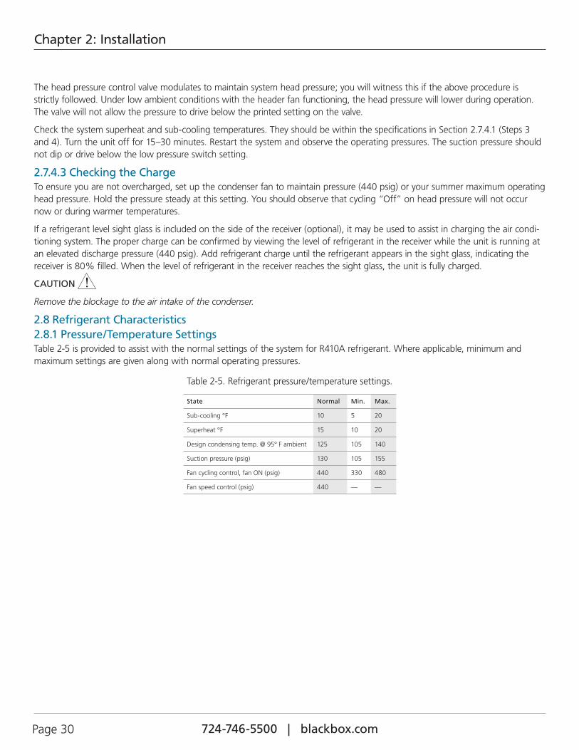
2.8 Refrigerant Characteristics2.8.1 Pressure/Temperature SettingsTable 2-5 is provided to assist with the normal settings of the system for R410A refrigerant. Where applicable, minimum and maximum settings are given along with normal operating pressures.
Table 2-5. Refrigerant pressure/temperature settings.
State Normal Min. Max.
Sub-cooling °F 10 5 20
Superheat °F 15 10 20
Design condensing temp. @ 95° F ambient 125 105 140
Suction pressure (psig) 130 105 155
Fan cycling control, fan ON (psig) 440 330 480
Fan speed control (psig) 440 — —
724-746-5500 | blackbox.com 724-746-5500 | blackbox.com Page 31
Chapter 2: Installation
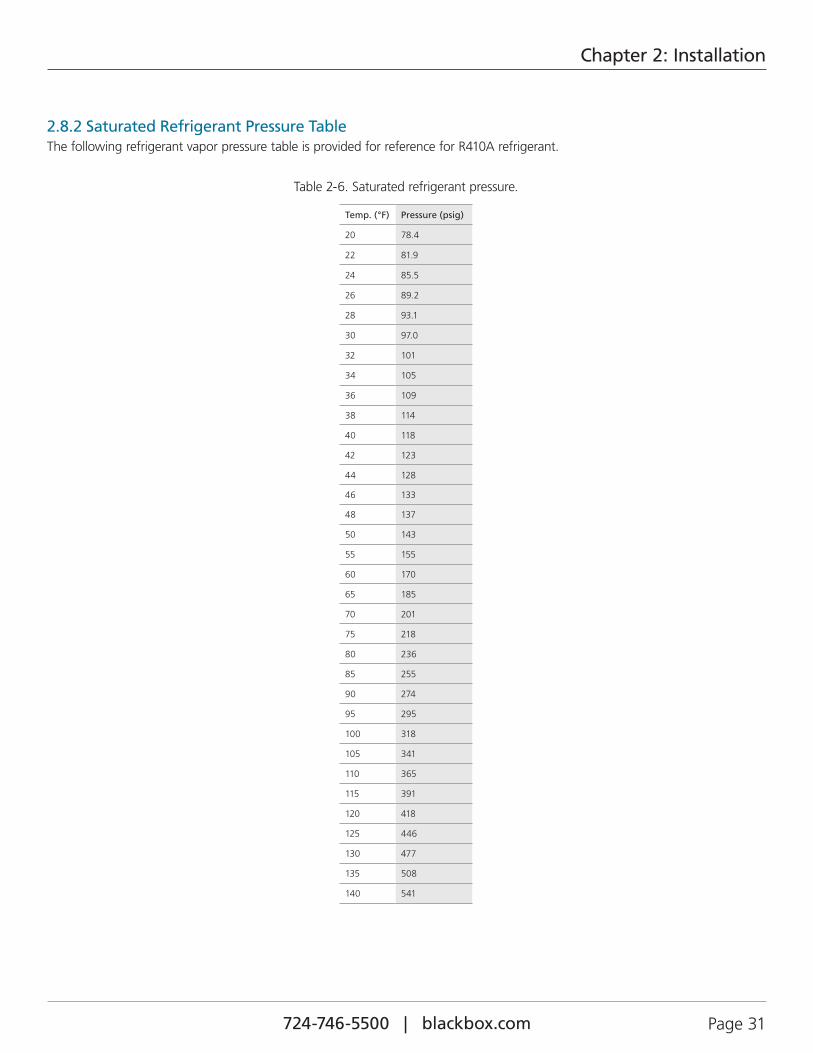
2.8.2 Saturated Refrigerant Pressure TableThe following refrigerant vapor pressure table is provided for reference for R410A refrigerant.
Table 2-6. Saturated refrigerant pressure.
Temp. (°F) Pressure (psig)
20 78.4
22 81.9
24 85.5
26 89.2
28 93.1
30 97.0
32 101
34 105
36 109
38 114
40 118
42 123
44 128
46 133
48 137
50 143
55 155
60 170
65 185
70 201
75 218
80 236
85 255
90 274
95 295
100 318
105 341
110 365
115 391
120 418
125 446
130 477
135 508
140 541
724-746-5500 | blackbox.com Page 32 724-746-5500 | blackbox.com
Chapter 3: Start-up/Commissioning
3. Startup/Commissioning3.1 OperationFor new installations, ensure the unit is ready to operate by going through the Checklist for Completed Installation, located in Section A.1, prior to startup.
NOTE: A Warranty Registration and Start-Up Checklist is provided with the unit data package. It should be completed during startup and sent to Black Box. This checklist should be used as a guideline for items that need to be confirmed during startup.
CAUTION
Startup must be performed by a qualified journeyman refrigeration mechanic or air-conditioning technician.
3.2 Step-by-Step Startup Instructions1. Replace all equipment removed prior to performing startup checks.
2. Apply power to the condenser at the main power disconnect switch.
The refrigeration circuit must be tested at startup. Refer to the separate controller operation instructions sent in the data package with your unit.
3. Test cooling operation by adjusting the temperature setpoint at the system controller. The compressor should come on and the suction line temperature should gradually drop.
4. Ensure the fan(s) are rotating correctly and freely without any unusual noise.
3.3 Operational Description1. When used with a Black Box indoor evaporator unit, the A/C system compressor starts, then the condenser fan(s) start.
Operation of the condenser fans is dependent on the head pressure control method used. See the descriptions for head pressure controls in Section 1.3.
2. Cold Row Air-Cooled Condensers may be configured for standalone operation. In this case, the fans begin operating when power is turned on.
3. Refrigerant flowing from the evaporator in the form of a low-pressure gas enters the compressor where it is compressed into a high-temperature, high-pressure gas.
4. The refrigerant then flows to the condenser coil. The high-temperature, high-pressure gas from the compressor is cooled by the flow of air through the condenser coil and is condensed into a high-pressure liquid.
5. For cold weather applications using flooded head pressure control, the low-temperature, high-pressure liquid refrigerant flows to a receiver. The receiver acts as a storage tank for the liquid refrigerant that is not in circulation.
6. The refrigerant flows through a liquid sight glass. This device shows the presence of air, moisture, and the condition of the refrigerant in the system.
7. The low-temperature, high-pressure liquid refrigerant then flows to the evaporator where it removes heat and evaporates back into a gas.
8. The refrigerant gas is then drawn back to the compressor and the cycle is repeated.
724-746-5500 | blackbox.com 724-746-5500 | blackbox.com Page 33
Chapter 4: Maintenance/Repairs
4. Maintenance/Repairs4.1 Periodic General MaintenanceSystematic, periodic, general maintenance of the condenser is recommended for optimum system performance. General maintenance should include, but is not limited to the following:
1. Tighten electrical connections.
2. Clean the interior of the unit.
3. Inspect the unit’s components visually.
Use copies of the Periodic General Maintenance Checklist in this manual (see Section A.2) to record periodic general maintenance inspections. For assistance, contact Black Box Technical Support at 724-746-5500 or [email protected]. Ensure your adherence to all safety statements while performing any type of maintenance.
CAUTION
All maintenance and/or repairs must be performed by a journeyman refrigeration mechanic or air-conditioning technician.
WARNING
Turn off power to the unit at the main power disconnect switch unless you are performing tests that require power. To prevent personal injury, stay clear of rotating components, because automatic controls may start them unexpectedly. With power and controls energized, the fans could begin operating automatically at any time.
Hazardous voltage will still be present even with the unit turned off at the controller. To isolate the unit for maintenance, always turn off power at the main power disconnect switch prior to performing any service or repairs.
This unit uses high-voltage equipment with rotating components. Exercise extreme care to avoid accidents and ensure proper operation.
Maintenance access to the condenser is through the removable fan assembly panel on top of the unit. Examine the areas around the air inlet and outlet grills, fans, motors, and coils. Use a vacuum cleaner with a soft bristle brush to clean dirt from components.
Clean the coil of all debris that will inhibit airflow. This can be done with a vacuum cleaner, soft brush, and compressed air, or with a commercial coil cleaner. Check for bent or damaged coil fins and repair as necessary. On outdoor units, do not permit snow to accumulate on or around the unit in the winter. Check all refrigerant lines and capillaries for vibration isolation and support as necessary. Check all refrigerant lines for signs of leaks.
1. Examine all wiring for signs of chafing, loose connections, or other obvious damage (quarterly).
2. Examine brackets, motor mounts, and hardware for loose or missing parts or other damage (quarterly).
3. Clean accumulations of dust and dirt from all interior and exterior surfaces (quarterly).
NOTE: Fan motors have permanently sealed bearings, therefore, no lubrication is required.
4.2 TroubleshootingTurn off all power to the unit before conducting any troubleshooting procedures, unless the procedure specifically requires the system to operate. For troubleshooting purposes, the system may be operated with the electric box open by using a pair of channel lock pliers to turn the shaft of the main power disconnect switch to the “On” position. When the switch is turned on, high voltage will be present inside the box. Exercise caution to prevent injury. Keep hands, clothing, and tools clear of the electrical terminals and rotating components. Ensure that your footing is stable at all times.
WARNING
This equipment should be serviced and repaired by a journeyman or a qualified refrigeration technician only.
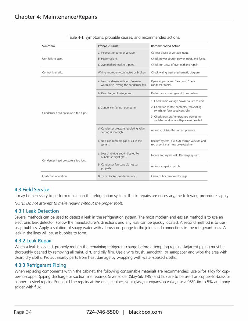
724-746-5500 | blackbox.com Page 34 724-746-5500 | blackbox.com
Chapter 4: Maintenance/Repairs
Table 4-1. Symptoms, probable causes, and recommended actions.
Symptom Probable Cause Recommended Action
Unit fails to start.
a. Incorrect phasing or voltage.
b. Power failure.
c. Overload protection tripped.
Correct phase or voltage input.
Check power source, power input, and fuses.
Check for cause of overload and repair.
Control is erratic. Wiring improperly connected or broken. Check wiring against schematic diagram.
Condenser head pressure is too high.
a. Low condenser airlfow. (Excessive warm air is leaving the condenser fan.)
Open air passages. Clean coil. Check condenser fan(s).
b. Overcharge of refrigerant. Reclaim excess refrigerant from system.
c. Condenser fan not operating.
1. Check main voltage power source to unit.
2. Check fan motor, contactor, fan cycling switch, or fan speed controller.
3. Check pressure/temperature operating switches and motor. Replace as needed.
d. Condenser pressure regulating valve setting is too high.
Adjust to obtain the correct pressure.
e. Non-condensable gas or air in the system.
Reclaim system, pull 500-micron vacuum and recharge. Install new dryer/strainer.
Condenser head pressure is too low.
a. Loss of refrigerant (indicated by bubbles in sight glass).
Locate and repair leak. Recharge system.
b. Condenser fan controls not set properly.
Adjust or repair controls.
Erratic fan operation. Dirty or blocked condenser coil. Clean coil or remove blockage.
4.3 Field ServiceIt may be necessary to perform repairs on the refrigeration system. If field repairs are necessary, the following procedures apply:
NOTE: Do not attempt to make repairs without the proper tools.
4.3.1 Leak DetectionSeveral methods can be used to detect a leak in the refrigeration system. The most modern and easiest method is to use an electronic leak detector. Follow the manufacturer’s directions and any leak can be quickly located. A second method is to use soap bubbles. Apply a solution of soapy water with a brush or sponge to the joints and connections in the refrigerant lines. A leak in the lines will cause bubbles to form.
4.3.2 Leak RepairWhen a leak is located, properly reclaim the remaining refrigerant charge before attempting repairs. Adjacent piping must be thoroughly cleaned by removing all paint, dirt, and oily film. Use a wire brush, sandcloth, or sandpaper and wipe the area with clean, dry cloths. Protect nearby parts from heat damage by wrapping with water-soaked cloths.
4.3.3 Refrigerant PipingWhen replacing components within the cabinet, the following consumable materials are recommended: Use Silfos alloy for cop-per-to-copper (piping discharge or suction line repairs). Silver solder (Stay-Silv #45) and flux are to be used on copper-to-brass or copper-to-steel repairs. For liquid line repairs at the drier, strainer, sight glass, or expansion valve, use a 95% tin to 5% antimony solder with flux.
724-746-5500 | blackbox.com 724-746-5500 | blackbox.com Page 35
Chapter 4: Maintenance/Repairs
When component replacement is complete, remove all traces of flux. After any repair, pressure check the system, checking for leaks prior to recharging the system.
4.3.4 Electrical SystemAll electrical connections should be checked to be sure that they are tight and properly made. Check all switches, contactors, and wiring. Contactors should be examined and replaced if the contact pads are worn or pitted.

724-746-5500 | blackbox.com Page 36 724-746-5500 | blackbox.com
Chapter 5: Product Support
5. Product SupportBlack Box provides its customers with product support that not only provides technical support and parts but the following additional services, as requested:
• Performance Evaluations
• Start-up Assistance
• Training
5.1 Technical SupportIf a problem develops that cannot be resolved using this manual, contact Black Box Technical Support at 724-746-5500 or [email protected].
When calling for Tech Support, it is important to have the following information readily available, (information is found on the unit’s nameplate):
• Unit Model Number
• Black Box Sales Order Number
• Black Box Item Number
• Unit Serial Number
• Description of Problem
5.2 Obtaining Warranty PartsWarranty inquiries are to be made through Black Box Technical Support at 724-746-5500 or [email protected]. A service technician at Black Box will troubleshoot the system over the telephone with a field service technician to determine the defect of the part. If it is determined that the part may be defective, a replacement part will be sent.
A written (or faxed) purchase order is required on warranty parts. The purchase order must contain the following items:
• Purchase Order Number
• Unit Model No., Serial No. and Black Box Item No.
• Date of Order
• Black Box Stated Part Price
• Customer Billing Address
• Shipping Address
• Customer’s Telephone and Fax Numbers
• Contact Name
The customer is responsible for the shipping cost incurred for returning the defective part(s) back to Black Box. Return of defective part(s) must be within 30 days, at which time an evaluation of the part(s) is conducted and if the part is found to have a manufacturing defect a credit will be issued.
When returning defective part(s), complete the Return Material Authorization Tag and the address label received with the replacement part.
See the Black Box Standard Warranty located in section one of this manual.
5.3 Obtaining Spare/Replacement PartsSpare and replacement parts requests are to be made through Black Box Technical Support. Contact us at 724-746-5500 or [email protected].
724-746-5500 | blackbox.com 724-746-5500 | blackbox.com Page 37
Chapter 5: Product Support
Quotes are given for specified listed parts for a specific unit.
A 25% minimum restocking charge will be applied on returned stocked parts that were sold as spare/replacement parts. If the returned part is not a stocked item, a 50% restocking charge may be applied. Additionally, a Return Material Authorization Number is required when returning parts. To receive credit for returned repair/replacement parts, the parts must be returned to Black Box within 30 days of the purchase date. Spare part sales over 30 days old will be considered final and the parts will remain the sole property of the ordering party.
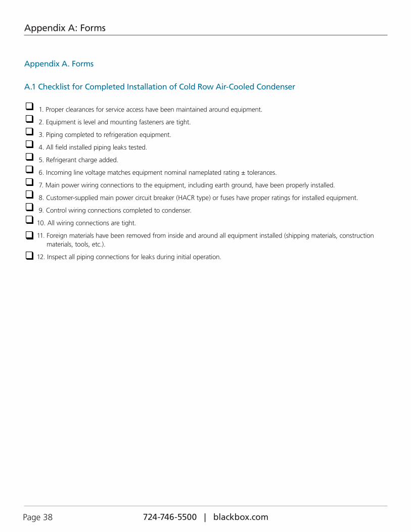
724-746-5500 | blackbox.com Page 38 724-746-5500 | blackbox.com
Appendix A: Forms
Appendix A. Forms
A.1 Checklist for Completed Installation of Cold Row Air-Cooled Condenser
1. Proper clearances for service access have been maintained around equipment.
2. Equipment is level and mounting fasteners are tight.
3. Piping completed to refrigeration equipment.
4. All field installed piping leaks tested.
5. Refrigerant charge added.
6. Incoming line voltage matches equipment nominal nameplated rating ± tolerances.
7. Main power wiring connections to the equipment, including earth ground, have been properly installed.
8. Customer-supplied main power circuit breaker (HACR type) or fuses have proper ratings for installed equipment.
9. Control wiring connections completed to condenser.
10. All wiring connections are tight.
11. Foreign materials have been removed from inside and around all equipment installed (shipping materials, construction materials, tools, etc.).
12. Inspect all piping connections for leaks during initial operation.
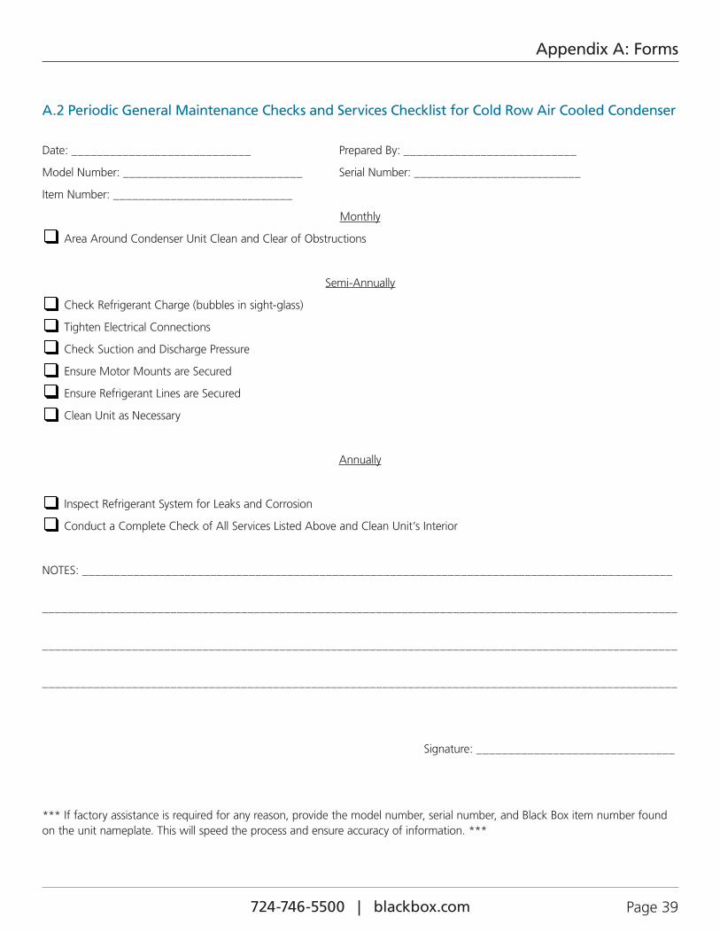
724-746-5500 | blackbox.com 724-746-5500 | blackbox.com Page 39
Appendix A: Forms
A.2 Periodic General Maintenance Checks and Services Checklist for Cold Row Air Cooled Condenser
Date: ____________________________ Prepared By: ___________________________
Model Number: ____________________________ Serial Number: __________________________
Item Number: ____________________________
Monthly
Area Around Condenser Unit Clean and Clear of Obstructions
Semi-Annually
Check Refrigerant Charge (bubbles in sight-glass)
Tighten Electrical Connections
Check Suction and Discharge Pressure
Ensure Motor Mounts are Secured
Ensure Refrigerant Lines are Secured
Clean Unit as Necessary
Annually
Inspect Refrigerant System for Leaks and Corrosion
Conduct a Complete Check of All Services Listed Above and Clean Unit’s Interior
NOTES: ____________________________________________________________________________________________
___________________________________________________________________________________________________
___________________________________________________________________________________________________
___________________________________________________________________________________________________
Signature: _______________________________
*** If factory assistance is required for any reason, provide the model number, serial number, and Black Box item number found on the unit nameplate. This will speed the process and ensure accuracy of information. ***
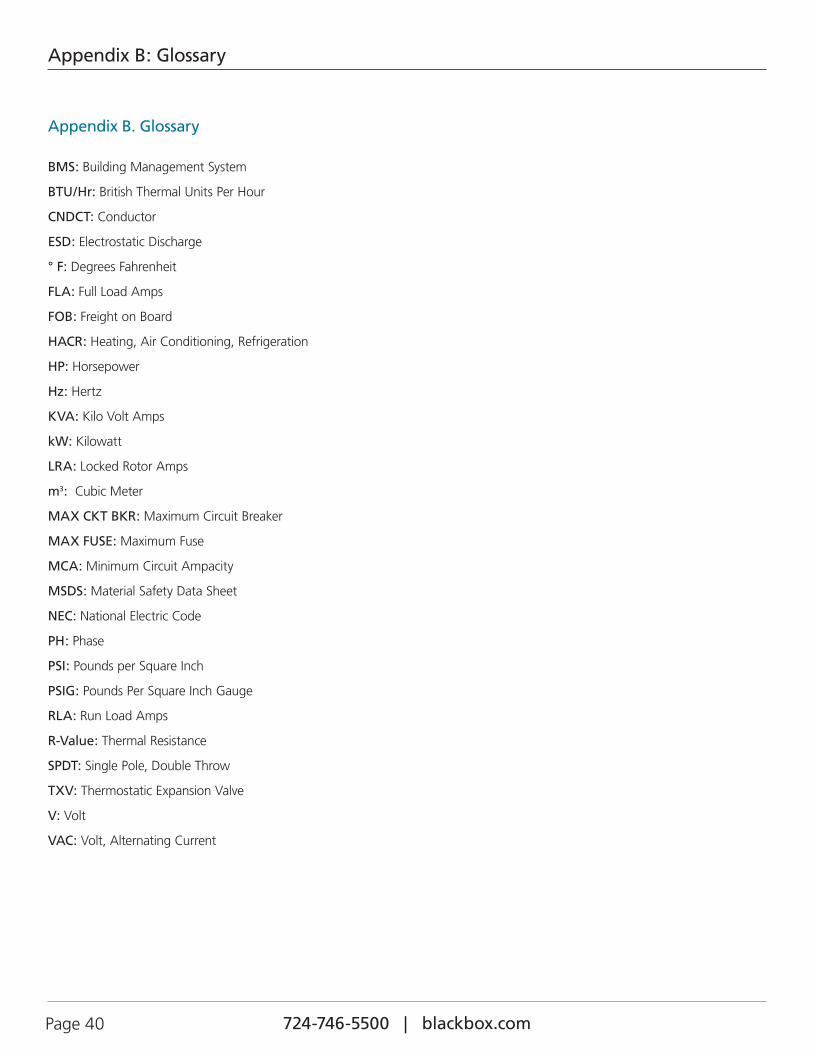
724-746-5500 | blackbox.com Page 40 724-746-5500 | blackbox.com
Appendix B: Glossary
Appendix B. Glossary
BMS: Building Management System
BTU/Hr: British Thermal Units Per Hour
CNDCT: Conductor
ESD: Electrostatic Discharge
° F: Degrees Fahrenheit
FLA: Full Load Amps
FOB: Freight on Board
HACR: Heating, Air Conditioning, Refrigeration
HP: Horsepower
Hz: Hertz
KVA: Kilo Volt Amps
kW: Kilowatt
LRA: Locked Rotor Amps
m3: Cubic Meter
MAX CKT BKR: Maximum Circuit Breaker
MAX FUSE: Maximum Fuse
MCA: Minimum Circuit Ampacity
MSDS: Material Safety Data Sheet
NEC: National Electric Code
PH: Phase
PSI: Pounds per Square Inch
PSIG: Pounds Per Square Inch Gauge
RLA: Run Load Amps
R-Value: Thermal Resistance
SPDT: Single Pole, Double Throw
TXV: Thermostatic Expansion Valve
V: Volt
VAC: Volt, Alternating Current

724-746-5500 | blackbox.com 724-746-5500 | blackbox.com Page 41
NOTES
724-746-5500 | blackbox.com Page 42 724-746-5500 | blackbox.com
NOTES
724-746-5500 | blackbox.com 724-746-5500 | blackbox.com Page 43
NOTES

724-746-5500 | blackbox.com
About Black BoxBlack Box provides an extensive range of networking and infrastructure products. You’ll find everything from cabinets and racks and power and surge protection products to media converters and Ethernet switches all supported by free, live 24/7 Tech support available in 30 seconds or less.
© Copyright 2012. Black Box Corporation. All rights reserved.
BLACK BOX®
Black Box Tech Support: FREE! Live. 24/7.
Tech support the way it should be.
Great tech support is just 30 seconds away at 724-746-5500 or blackbox.com.
BB-060-SSA, version 1
BB-ORS0014-D; June, 2012


![Second Revision No. 1-NFPA 17A-2016 [ Section No. 4.3.3 ]€¦ · Second Revision No. 1-NFPA 17A-2016 [ Section No. 4.3.3 ] 4.3.3 All discharge nozzles shall be provided with caps](https://img.pdfslide.us/doc/110x75/5f06813e7e708231d4185299/second-revision-no-1-nfpa-17a-2016-section-no-433-second-revision-no-1-nfpa.jpg)