Embed Size (px)
Citation preview
Journal of the Korea Academia-Industrial
Cooperation Society
Vol. 12, No. 9 pp. 4083-4094, 2011
http://dx.doi.org/10.5762/KAIS.2011.12.9.4083
4083
Review of BLAC Motor and Drive Technology
for Electric Power Steering of Vehicles
Kwan-Yuhl Cho1, Hak-Wone Kim1* and Young-Hoon Cho2
1Dept. of Control & Instrumentation Engineering, Chungju National University2Dept. of Electrical and Computer Engineering, Virginia Tech.
자동차용 EPS의 BLAC 모터 및 제어기술의 고찰
조관열1, 김학원1*, 조영훈21충주대학교 제어계측공학과, 2버지니아테크 전기및컴퓨터공학과
Abstract The Electric Power Steering (EPS) has been applied to the vehicles due to its better fuel efficiency, better steering feel, and the compact volume compared to the hydraulic power steering. The brushed PM (Permanent Magnet) DC motors had been adopted in most of the EPS systems until several years ago due to its easy control and a simple hardware configuration of the power converter, but nowadays the BLAC (Brushless AC) motor is becoming more popular for the EPS system because of its high efficiency and long lifetime. This paper reviews the configuration of the EPS system and the BLAC motor and drive technologies based on the papers published recently. The torque ripple reduction for steering feel and the fault detection algorithms for safety are also reviewed.
요 약 전기식 파워 스티어링(EPS)은 유압식 파워스티어링에 비해 연비가 높고 스티어링 느낌이 좋으며 체적이 작으므로 자동차에 많이 적용되고 있다. 몇 년 전까지 대부분의 EPS 시스템에는 제어가 쉽고 하드웨어 구조가 간단한 영구자석 DC 모터가 주로 적용되었으나 최근에는 효율이 높고 수명이 긴 BLAC 모터가 적용되고 있다. 본 논문에서는 최근에 발표된 논문들을 기초로 EPS 시스템의 구조 및 BLAC 모터와 제어기술에 대해 고찰한다. 또한 스티어링 느낌을 좋게 하기 위한 토크리플 저감 및 안전을 위한 고장검출 알고리즘에 대해서도 검토한다.
Key Words : Electric Power Steering, BLAC motor, Torque ripple, Fault detection.
This work was supported by the Human Resources Development of the Korea Institute of Energy Technology Evaluation and Planning(KETEP) grant funded by the Ministry of Knowledge Economy, Republic of Korea(No. 2011H100100110)*Corresponding Author: Hag-Wone Kim([email protected])Received August 3, 2011 Revised September 5, 2011 Accepted September 8, 2011
1. Introduction
In recent years, energy savings in vehicles has been issues in the worldwide so that electric vehicles and hybrid electric vehicles, which are driven by electric motors, are being launched in the market. In addition, some hydraulic controlled mechanical systems have been replaced by electric driven systems, such as power steering and brake system. The existing power steering
system for vehicles can be categorized into three types, the hydraulic power steering that obtains steering assistant power directly from hydraulic pump driven by the engine, the EPS (Electric Power Steering) that is driven by an electric motor, and the EHPS (Electric Hydraulic Power Steering) that the hydraulic pump for steering assistance is driven by an electric motor. Compared to the hydraulic power steering system, the EPS has shown better fuel efficiency, better steering feel, environment friendly,
한국산학기술학회논문지 제12권 제9호, 2011
4084
reduced manufacturing time on the production line, and it also offers more space in the engine compartment due to the down-sizing with the reduced component [1-3]. Due to these benefits, both the EPS and the EHPS shared about 35% of the power steering world market in 2007 and its portion in the market share has been continually increased [2].
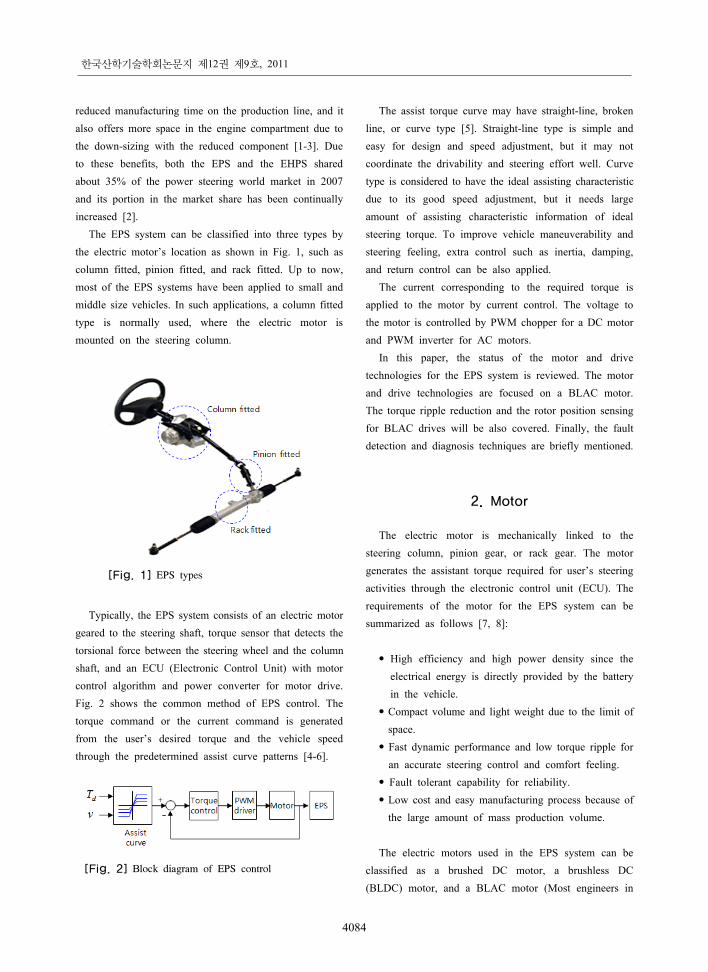
The EPS system can be classified into three types by the electric motor’s location as shown in Fig. 1, such as column fitted, pinion fitted, and rack fitted. Up to now, most of the EPS systems have been applied to small and middle size vehicles. In such applications, a column fitted type is normally used, where the electric motor is mounted on the steering column.
[Fig. 1] EPS types
Typically, the EPS system consists of an electric motor geared to the steering shaft, torque sensor that detects the torsional force between the steering wheel and the column shaft, and an ECU (Electronic Control Unit) with motor control algorithm and power converter for motor drive. Fig. 2 shows the common method of EPS control. The torque command or the current command is generated from the user’s desired torque and the vehicle speed through the predetermined assist curve patterns [4-6].
[Fig. 2] Block diagram of EPS control
The assist torque curve may have straight-line, broken line, or curve type [5]. Straight-line type is simple and easy for design and speed adjustment, but it may not coordinate the drivability and steering effort well. Curve type is considered to have the ideal assisting characteristic due to its good speed adjustment, but it needs large amount of assisting characteristic information of ideal steering torque. To improve vehicle maneuverability and steering feeling, extra control such as inertia, damping, and return control can be also applied.
The current corresponding to the required torque is applied to the motor by current control. The voltage to the motor is controlled by PWM chopper for a DC motor and PWM inverter for AC motors.
In this paper, the status of the motor and drive technologies for the EPS system is reviewed. The motor and drive technologies are focused on a BLAC motor. The torque ripple reduction and the rotor position sensing for BLAC drives will be also covered. Finally, the fault detection and diagnosis techniques are briefly mentioned.
2. Motor
The electric motor is mechanically linked to the steering column, pinion gear, or rack gear. The motor generates the assistant torque required for user’s steering activities through the electronic control unit (ECU). The requirements of the motor for the EPS system can be summarized as follows [7, 8]:
• High efficiency and high power density since the
electrical energy is directly provided by the battery in the vehicle.
• Compact volume and light weight due to the limit of space.
• Fast dynamic performance and low torque ripple for an accurate steering control and comfort feeling.
• Fault tolerant capability for reliability.• Low cost and easy manufacturing process because of
the large amount of mass production volume. The electric motors used in the EPS system can be
classified as a brushed DC motor, a brushless DC (BLDC) motor, and a BLAC motor (Most engineers in
Review of BLAC Motor and Drive Technology for Electric Power Steering of Vehicles
4085
the field of vehicles call a PM synchronous motor as a BLAC motor) as shown in Table I. The brushed PM DC motor had been widely adopted in most of the EPS systems until several years ago due to its easy control and a simple hardware configuration of the power converter. However, the brushed DC motor has limitations in short life cycle due to the brushes, a spark and noise caused by the mechanical commutation, small power capacity, and slow dynamic response due to the large moment of rotor inertia resulted from the windings in the rotor.
[Table 1] Motors for EPS system
Brushed
DC motor
BLDC
motor
BLAC
motor
Control SimpleSquare
current
Sinusoidal
current
Power
converter
PWM
chopper
PWM
inverter
PWM
inverter
Rotor position
sensor
Not
required
Low
resolution
High
resolution
Efficiency Low Medium High
Inertia High Low Low
Friction High Low Low
Torque ripple Good Poor Good
The brushless motor can overcome the limitations caused by the brushes in a brushed DC motor. The brushless motor includes an induction motor, a synchronous motor, and a reluctance motor. The BLDC motor driven by square wave currents is easy to control since the commutation occurs every 60 electrical degrees. Compare to the BLAC motor which requires sinusoidal currents, utilization of a cheap position sensor and high power density make the BLDC motor more attractive [9]. However the BLDC motor has large amount of torque ripples synchronized to every commutation cycle due to the ripples in phase currents and non-ideal trapezoidal shapes of the back emf.
The most competitive solution in current market for the EPS application could be a BLAC motor. The high torque density, quite low cogging torque, low torque pulsations, and energy effective features are the key factors that this type of motor is getting popular in the EPS applications [10]. The drawback of the BLAC motor is the requirement of the rotor position sensors with high
resolution to apply the sinusoidal currents to the motor. To overcome the drawback, the low cost position sensor drives for the BLAC motor will be discussed in the later section.
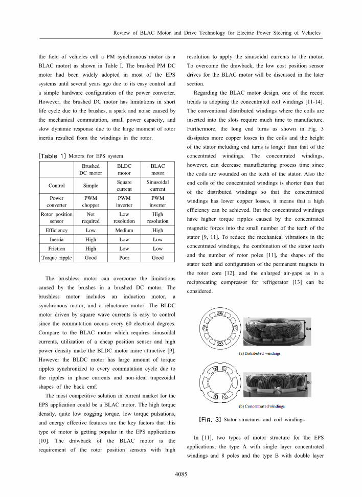
Regarding the BLAC motor design, one of the recent trends is adopting the concentrated coil windings [11-14]. The conventional distributed windings where the coils are inserted into the slots require much time to manufacture. Furthermore, the long end turns as shown in Fig. 3 dissipates more copper losses in the coils and the height of the stator including end turns is longer than that of the concentrated windings. The concentrated windings, however, can decrease manufacturing process time since the coils are wounded on the teeth of the stator. Also the end coils of the concentrated windings is shorter than that of the distributed windings so that the concentrated windings has lower copper losses, it means that a high efficiency can be achieved. But the concentrated windings have higher torque ripples caused by the concentrated magnetic forces into the small number of the teeth of the stator [9, 11]. To reduce the mechanical vibrations in the concentrated windings, the combination of the stator teeth and the number of rotor poles [11], the shapes of the stator teeth and configuration of the permanent magnets in the rotor core [12], and the enlarged air-gaps as in a reciprocating compressor for refrigerator [13] can be considered.
[Fig. 3] Stator structures and coil windings
In [11], two types of motor structure for the EPS applications, the type A with single layer concentrated windings and 8 poles and the type B with double layer
한국산학기술학회논문지 제12권 제9호, 2011
4086
concentrated windings and 10 poles, are compared, while both types incorporate same 12 stator teeth. The type B has advantages in the maximum output torque and less torque ripples including cogging torque, while it has a little larger stator deformation than the type A.
The production process of BLAC motors will be also simplified by use of new soft magnetic composites (SMC), with this type of material, it is possible to produce the stator in several pieces, to install the pre-fabricated concentrated windings in the fully opened slots, and to complete the final assembly by installing the tooth tips [14]. The SMC materials, however, has some drawbacks such as low flux density, low mechanical strength, and high cost compared to the laminated silicon steels.
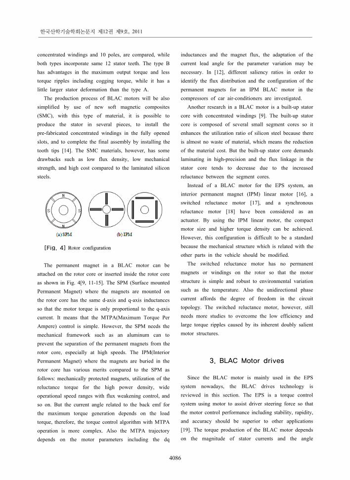
[Fig. 4] Rotor configuration
The permanent magnet in a BLAC motor can be attached on the rotor core or inserted inside the rotor core as shown in Fig. 4[9, 11-15]. The SPM (Surface mounted Permanent Magnet) where the magnets are mounted on the rotor core has the same d-axis and q-axis inductances so that the motor torque is only proportional to the q-axis current. It means that the MTPA(Maximum Torque Per Ampere) control is simple. However, the SPM needs the mechanical framework such as an aluminum can to prevent the separation of the permanent magnets from the rotor core, especially at high speeds. The IPM(Interior Permanent Magnet) where the magnets are buried in the rotor core has various merits compared to the SPM as follows: mechanically protected magnets, utilization of the reluctance torque for the high power density, wide operational speed ranges with flux weakening control, and so on. But the current angle related to the back emf for the maximum torque generation depends on the load torque, therefore, the torque control algorithm with MTPA operation is more complex. Also the MTPA trajectory depends on the motor parameters including the dq
inductances and the magnet flux, the adaptation of the current lead angle for the parameter variation may be necessary. In [12], different saliency ratios in order to identify the flux distribution and the configuration of the permanent magnets for an IPM BLAC motor in the compressors of car air-conditioners are investigated.
Another research in a BLAC motor is a built-up stator core with concentrated windings [9]. The built-up stator core is composed of several small segment cores so it enhances the utilization ratio of silicon steel because there is almost no waste of material, which means the reduction of the material cost. But the built-up stator core demands laminating in high-precision and the flux linkage in the stator core tends to decrease due to the increased reluctance between the segment cores.
Instead of a BLAC motor for the EPS system, an interior permanent magnet (IPM) linear motor [16], a switched reluctance motor [17], and a synchronous reluctance motor [18] have been considered as an actuator. By using the IPM linear motor, the compact motor size and higher torque density can be achieved. However, this configuration is difficult to be a standard because the mechanical structure which is related with the other parts in the vehicle should be modified.
The switched reluctance motor has no permanent magnets or windings on the rotor so that the motor structure is simple and robust to environmental variation such as the temperature. Also the unidirectional phase current affords the degree of freedom in the circuit topology. The switched reluctance motor, however, still needs more studies to overcome the low efficiency and large torque ripples caused by its inherent doubly salient motor structures.
3. BLAC Motor drives
Since the BLAC motor is mainly used in the EPS system nowadays, the BLAC drives technology is reviewed in this section. The EPS is a torque control system using motor to assist driver steering force so that the motor control performance including stability, rapidity, and accuracy should be superior to other applications [19]. The torque production of the BLAC motor depends on the magnitude of stator currents and the angle
Review of BLAC Motor and Drive Technology for Electric Power Steering of Vehicles
4087
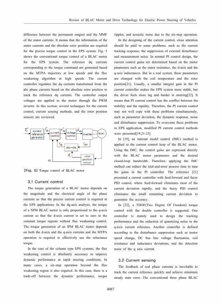
difference between the permanent magnet and the MMF of the stator currents. It means that the information of the stator currents and the absolute rotor position are required for the precise torque control in the EPS system. Fig. 5 shows the conventional torque control of a BLAC motor for the EPS system. The reference dq currents corresponding to the torque command are generated based on the MTPA trajectory at low speeds and the flux weakening algorithm at high speeds. The current controller regulates the dq currents transformed from the abc phase currents based on the absolute rotor position to track the reference dq currents. The controller output voltages are applied to the motor through the PWM inverter. In this section, several techniques for the current control, current sensing methods, and the rotor position sensors are reviewed.
[Fig. 5] Torque control of BLAC motor
3.1 Current control
The torque generation of a BLAC motor depends on the magnitude and the electrical angle of the phase currents so that the precise current control is required in the EPS applications. In the dq-axis analysis, the torque of a SPM BLAC motor is only proportional to the q-axis current so that the d-axis current is set to zero in the constant torque regions without flux weakening control. The torque generation of an IPM BLAC motor depends on both the d-axis and the q-axis currents and the MTPA operation is required to effectively use the reluctance torque.
In the case of the column type EPS systems, the flux weakening control is absolutely necessary to improve dynamic performance at rapid steering conditions. In many cases, a six-step operation beyond the flux weakening region is also required. In this case, there is a trade-off between the dynamic performance, torque
ripples, and acoustic noise due to the six-step operation. In the designing of the current control, close attention
should be paid to some problems, such as the current tracking response, the suppression of external disturbance and measurement noise. In normal PI control design, the current control gains are determined based on the motor parameters such as the stator resistance, the d-axis and the q-axis inductances. But in a real system, these parameters are changed with the coil temperature and the rotor position[21]. Usually, a smaller integral gain in the PI current controller makes the EPS system more stable, but the driver feels more lag and harder in steering[22]. It means that PI current control has the conflict between the stability and the rapidity. Therefore, the PI current control may not well cope with these problems simultaneously, such as parameter deviation, the dynamic response, noise and disturbance suppression. To overcome these problems in EPS application, modified PI current control methods were presented[19,21-23].
In [19], an internal model control (IMC) method is applied to the current control loop of the BLAC motor. Using the IMC, the control gains are expressed directly with the BLAC motor parameters and the desired closed-loop bandwidth. Therefore, applying the IMC method can reduce the trial-and-error process time to tune the gains in the PI controller. The reference [21] presented a current controller with feed-forward and fuzzy PID control, where feed-forward eliminates most of the current deviation rapidly, and the fuzzy PID control eliminates the small remaining current deviation to guarantee the accuracy.
In [22], a TDOF(Two Degree Of Freedom) torque control with the double controller is suggested. One controller is mainly used to design the tracking performance and the reduction of quantizing noise in the q-axis current reference. Another controller is defined according to the disturbance suppression such as motor speed change, DC bus line voltage fluctuation, coil resistance and inductance deviations, and the detection noise of the q axis current.
3.2 Current sensing
The feedback of real phase currents is inevitable to track the current reference quickly and achieve minimum steady state error. The conventional three phase BLAC
한국산학기술학회논문지 제12권 제9호, 2011
4088
motor control system employs the hall-effect current sensors in two of the three phases. To reduce the cost for current sensing, the phase currents can be measured through 3 shunt resistors at the bottom of each leg of the three phase PWM inverter, requiring 3 sets of sense resistor, amplifier, and filter. This current sensing method may have difficulty in maintaining the same current measurement gain for three phase currents as a result of variations among sense resistors and op-amp parameter [24].
The three-phase VSI (Voltage Source Inverter) topology allows for further reduction of the number of current sensors through the reconstruction of the phase currents from the dc-link current signal. The SVPWM (Space Vector PWM) with optimal voltage vector sequencing allows for two phase currents to be detected in each switching period, and the third is reconstructed from these two. The dc link current sensing method has been reported in many literatures [24-27] and [24] demonstrated its feasibility in the EPS application by using a DSP controller. But the paper did not explain in detail how to correct the current measurement error in dead zones where two phase currents may not be detected accurately, in case that the voltage vector is in the boundary region between adjacent voltage sectors and the voltage vector is relatively small at low power.
3.3 Rotor position sensor
In the BLAC drives, the sinusoidal currents in three phase windings eliminate commutation transients existed in the BLDC drives and result in significant torque ripple reduction. However, the BLAC drives require accurate measurements of the rotor position for its control. The standard solution is to fit a high-resolution position sensor such as the resolver and the absolute encoder directly attached to the motor shaft. But these high-resolution position sensors can be viewed as expensive and may be restricted in use due to the increased volume of the sensors. A sensorless algorithm for the EPS system was presented in [28], where the rotor position is estimated from the Luenberger observer with the observer gains selection based on the results from the GA (Genetic Algorithms) online. Although sensorless controls without rotor position sensors may be applied to the EPS system, a physical sensor is still required due to the stringent
safety and reliability requirements of the EPS system [29]. Therefore, low cost rotor position sensors consisting of a magnet wheel, hall-effect sensors, and an incremental encoder are commonly used in the EPS systems. The absolute rotor position is detected by combining the absolute rotor position with 60 electrical degrees obtained from Hall-effect sensors and the high resolution incremented position obtained from an incremental encoder. The incremental encoder drive IC may be replaced by low cost hall-effect sensors to reduce the material cost, but the rotor position information with low resolution increases the torque ripple since the large quantization errors in the rotor position generates the current errors and phase delays in the dq currents[29,30]. In[30], using the low resolution encoder signals, the motor speed was estimated by measuring the period of the adjacent rising edges of the encoder signals. The period between the adjacent rising edges of the encoder signals can be measured by counting the number of high frequency counting signals. This method needs correction of the rotor position when the low resolution encoder signals have uneven pulse duration and phase offsets due to the uneven magnetization of the magnet wheel.
Further cost reduction can be achieved by removing the incremental encoder for the rotor speed detection [31-34], although the feasibility of the application to the EPS system was not reported. Then the rotor position can be detected by only hall-effect sensors, therefore, the rotor position information can be detected every 60 electric degrees, similar to the BLDC drives.
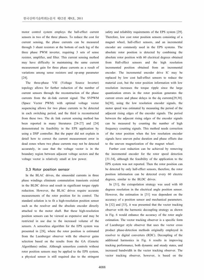
In [31], the extrapolation strategy was used with 60 degrees resolution in the electrical angle position sensor. However, the estimation in [31] was dependent on the accuracy of a position sensor and mechanical parameters. In [32] and [33], it was presented that the vector tracking observer with the harmonic decoupling strategy as shown in Fig. 6 would enhance the accuracy of the rotor angle estimation. The vector tracking observer is a specific form of Luenberger style observer that uses the vector cross product phase-detection methods originally employed in resolver to digital converters (RDC). Decoupling of the additional harmonics in Fig. 6 results in improving tracking performance, both dynamic and steady states, and increased bandwidth in the vector tracking observer. The vector tracking observer, however, is based on the
Review of BLAC Motor and Drive Technology for Electric Power Steering of Vehicles
4089
[Fig. 6] Vector tracking observer with harmonics decoupling
mechanical model of the BLAC motor, so the bandwidth of the observer is sensitive to the moment of inertia. Also, the method still suffers in estimating the rotor position at low speeds.
The reference [34] proposed a software technique with only two hall-effect sensors for the direct drive washer, where the rotor position detecting algorithm is based on a dual observer and a position sensor offset compensation strategy. The dual observer can estimate the rotor speed and position without time delay or bumps. With the compensation algorithm for position sensor offsets, the misaligned synchronous reference frame of d-axis and q-axis can be corrected.
4. Torque ripple reduction
EPS application, very low mechanical vibration is required to maintain a good steering feeling. The mechanical vibrations are mainly generated by the torque ripples of the motor so that reducing torque ripples is essential. Although there are various specific sources of torque harmonics in a BLAC motor, the torque ripples can be classified into two categories, cogging torque and ripple torque [35]. The cogging torque is the pulsating torque generated by the interaction of the rotor magnetic flux and angular variations in the stator magnetic reluctance. The ripple torque is the fluctuated torque generated by the interaction of stator current MMFs and rotor electromagnetic properties, which is caused by the non sinusoidal waveforms in the rotor magnet flux distribution.
Several techniques have been proposed to reduce the torque ripples in the BLAC motor drives [35-42]. These techniques can be summarized as two categories, the motor structure based approach and the motor control based approach.
In EPS applications, the techniques based on the motor structure has been focused on the reducing the cogging torque while the motor control based methods have been focused on the reducing the ripple torque by active current control schemes that modify the current waveforms to correct for any of the non-ideal characteristics of the motor or its associated power inverter.
The cogging torque in the BLAC motor is produced by stator teeth or slots interacting with the permanent magnets of the rotor, i.e., independent of the stator currents. The cogging torque can be reduced by increasing air gap, skewed rotor, fractional slot, increasing air gap, and adding the notches in the surface of the stator similar to the teeth of the stepping motor [36], etc. Increasing air gap reduces the effective magnetic flux on the stator so that larger current is required to generate the same torque. Therefore, the fractional slot or skewed rotor would be the effective approach for reducing the cogging torque in the BLAC motor [37].
The effectiveness of skewed rotor and the modified rotor structure with pole shifting on the torque ripples are presented in [36-41]. It was shown in [37] that the fractional slots with 9 slots and 8 poles has lower cogging toque than the non fractional slots with 9 slots and 6 poles. It was also provided the split skewed rotor with double permanent magnet layers can reduce the cogging
한국산학기술학회논문지 제12권 제9호, 2011
4090
torque considerably compared to the straight slots and poles. In practical applications, double layers of permanent magnets for split skewing would cause a complex rotor structure such as an insufficient double layer spaces, complex manufacturing process, and increasing manufacturing cost.
For control based torque ripple reduction methods, active cancellation of the torque ripples with extra current injection to the current reference was suggested [42,43]. The torque ripple consists of many harmonics including 6th, 12th order, and higher orders. The dominant harmonics are the 6th and the 12th order and the current control bandwidth is limited so that the compensating current including the 6th and the 12th order is added to the q-axis current reference. The compensating currents that cancel the particular torque harmonics are added to the current reference, where the compensating current is derived from the nonlinear analysis of magnet saturation[42]. In [43], compensation method to reduce current distortion caused by switching device voltage drops and dead time for low voltage and high current applications is demonstrated.
5. Fault Diagnosis
Faults generated in each device in the EPS system can cause an unexpected steering force. This unexpected steering force can make the driver panic and make a mistake so that it may cause serious problems on a vehicle safety. For any kinds of EPS systems, safety should be considered as the most important factor. Therefore, even in the event of system faults during vehicle operation, it is important to maintain the original function of the device, even allowing degraded way, in order to authorize the vehicle driver to confront this situation. The faults in the EPS system may be occurred in the sensors, electronic circuits, and the electric motor. The faults in the sensors include the failures in the torque sensors, the current sensors, and the rotor position sensors. The major faults in the electronics circuits are the damages in the power switches. The electric motor faults include broken wires, short circuits between adjacent wires, the demagnetization in the permanent magnets, and the eccentric of the ball bearings. Many papers on the
fault detection and fault tolerant diagnosis have been reported in the BLAC applications. In the EPS applications, however, not so much papers have been reported [44-49].
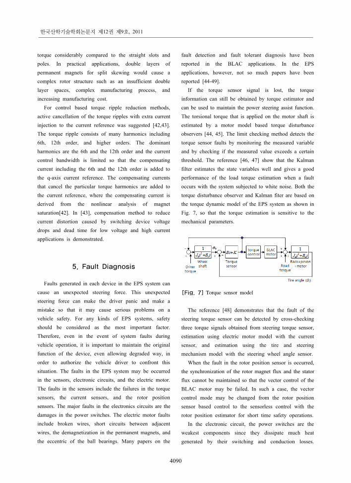
If the torque sensor signal is lost, the torque information can still be obtained by torque estimator and can be used to maintain the power steering assist function. The torsional torque that is applied on the motor shaft is estimated by a motor model based torque disturbance observers [44, 45]. The limit checking method detects the torque sensor faults by monitoring the measured variable and by checking if the measured value exceeds a certain threshold. The reference [46, 47] show that the Kalman filter estimates the state variables well and gives a good performance of the load torque estimation when a fault occurs with the system subjected to white noise. Both the torque disturbance observer and Kalman fiter are based on the torque dynamic model of the EPS system as shown in Fig. 7, so that the torque estimation is sensitive to the mechanical parameters.
[Fig. 7] Torque sensor model
The reference [48] demonstrates that the fault of the steering torque sensor can be detected by cross-checking three torque signals obtained from steering torque sensor, estimation using electric motor model with the current sensor, and estimation using the tire and steering mechanism model with the steering wheel angle sensor.
When the fault in the rotor position sensor is occurred, the synchronization of the rotor magnet flux and the stator flux cannot be maintained so that the vector control of the BLAC motor may be failed. In such a case, the vector control mode may be changed from the rotor position sensor based control to the sensorless control with the rotor position estimator for short time safety operations.
In the electronic circuit, the power switches are the weakest components since they dissipate much heat generated by their switching and conduction losses.
Review of BLAC Motor and Drive Technology for Electric Power Steering of Vehicles
4091
Another potential reason of the power switch failure is the short-through fault in the upper and lower switches of each phase, which may be caused by insufficient dead time and the noise in the gate drive signals. For a fault tolerant control (FTC) of the three-phase BLAC motor under the fault in power switches, two-phase operation without one damaged phase can be considered. However, the mode change to two-phase operation from three-phase operation should be carried out quickly to minimize the torque control error. For more reliable FTC under the power switch fault, multi-phase motor configuration can be considered [10, 49]. The reference [49] suggested a six-phase BLDC motor oriented towards the stator windings, number of phases and commutation sequences. An advantage of multi-phase machine drives over conventional three-phase equivalent machines would result in a more reliable fault tolerant system in case one or more stator phases are lost. The use of a six-phase machine with symmetrical 60 degrees displacement windings allows a high reliability. In fact, with a failure of one or several phases, the machine will still be able to run with a significant electromagnetic torque only limited by the windings thermal harshness.
6. Conclusion
In this paper, recent technologies of motor and drives for the EPS system were reviewed. The main issue in the BLAC motor is the concentrated windings, which has the merits such as the reduced manufacturing cost and the less copper losses compared to the distributed windings. Another issue in the BLAC motor is utilizing the IPM rotor structure, which has high efficiency due to the additional reluctance torque and the high speed operation with wide flux weakening control compared to the SPM rotor structure.
In the control of the BLAC motor, the vector control generally used in other applications including the industrial and servo drives is adopted. To reduce the cost of the rotor position sensor, the hall-effect sensor with high resolution incremental encoder is used as the rotor position sensor. The vector control with sinusoidal currents by only hall-effect sensors without incremental encoder can be applied to the EPS system.
The torque ripples can be reduced by injecting the harmonic currents that cancels the torque ripples. The source and the evolving process of the torque ripples in the EPS system are complicated and the torque ripple includes so many harmonic components. Even with the existing torque ripple reduction methods based on the feed-forward controllers to cancel out pre-determined certain harmonic components, all significant torque ripples component cannot be fully covered. Therefore, an online torque ripple detection method with high bandwidth and fast response can be a good candidate for study.
The faults detection and processing are a very important issue in the EPS application. In spite of such an important safety issue, the research concerning the FTC has been not exuberant relatively. A fault in the torque sensor can be detected by the torque disturbance observer and state observer. More studies about the fault monitoring algorithm and the fault tolerant control needs to be conducted.
References
[1] A. W. Burton, “Innovation drivers for electric power assisted steering,” IEEE Control Systems Magazine, pp. 30-39, Nov. 2003.
[2] H. Eki, T. Teratani, and T. Iwasaki, “Power consumption and conversion of EPS systems,” Power Conversion Conference(PCC), pp. 1333-1339, 2007.
[3] G. Ombach and J. Junak, “Two rotors designs’ comparison of permanent magnet brushless synchronous motor for an electric power steering application,” European Conference on Power Electronics and Applications (EPE), pp. 1-9, 2007.
[4] L. Q. Jin, C. X. Song, and C. J. Hu, “Driving force power steering for the electric vehicles with motorized wheels,” Vehicle Power and Propulsion Conference (VPPC), pp. 1518-1524, 2009.
[5] L. Yi, S. Guobiao, and Z. Changfeng, “Study on control strategy of electric power steering,” Automobile Technology, pp. 8-11, No.3, 2003.
[6] T. S. Hu, C. J. Yeh, S. R. Ho, T. H. Hsu, and M. C. Lin, “Design of control logic and compensation strategy for electric power steering systems,” Vehicle Power and Propulsion Conference, pp. 1-6, 2008.
한국산학기술학회논문지 제12권 제9호, 2011
4092
[7] H. Zhang, J. Liu, J. Ren, Y. Zhang, and Y. Gao, “Research on Electric Power Steering with BLDC drive system,” International Power Electronics and Motion Control Conference, pp. 1065-1069, 2009.
[8] N. Bianchi, M. D. Pre, and S. Bolognani, “Design of a fault-tolerant IPM motor for electric power steering,” IEEE Transactions on Vehicular Technology, Vol. 55, No. 4,pp. 1102-1111, 2006.
[9] L. Xinhua, W. Jie, Z. Zhiwei, and Z. Baixing, “Development of EPS rare-earth permanent-magnet brushless direct current motor,” Proc. of International Conference on Electrical Machines and Systems (ICEMS),Vol. 3, pp. 2302-2305, 2005.
[10] A. Matyas, G. Aroquiadassou, C. Martis, A. M. Mabwe, and K. Biro,” Design of six-phase synchronous and induction machines for EPS,” International Conference on Electrical Machines (ICEM), 2010.
[11] G. Ombach and J.Junak,” Comparison of double-layer interior permanent magnet synchronous motor design with two different pole numbers,” International Conference on Electrical Machines (ICEM), pp. 1–6, 2008.
[12] H. Murakami, H. Kataoka, Y. Honda, S. Morimoto, and Y. Takeda, “Highly eEfficient Brushless motor design for an air-conditioner of the next generation 42V vehicle,” Conference Record of Industry Applications Society Annual Meeting (IAS), pp. 461-466, 2001.
[13] Y. Asano, Y. Honda, H. Murakami, Y. Takeda, and S. Morimoto,” Novel noise improvement technique for a PMSM with concentrated winding,” Power Conversion Conference (PCC), pp. 460-465, 2002.
[14] J. Cros and P. Viarouge, “Synthesis of high performance PM motors with concentrated windings,” IEEE Trans. on Energy Conversion, Vol. 17, No. 2, pp. 248-253, June 2002.
[15] G. Aroquiadassou, H. Henao, V. Lanfranchi, F. Betin, B. Nahidmobarakeh, G. A. Capolino, M. Biedinger, and G. Friedrich, “Design comparison of two rotating electrical machines for 42 V electric power steering,“ International Conference on Electric Machines and Drives (IEMDC), pp. 431-436, 2005.
[16] H. Akhondi, J. Milimonfared, and H. Rastegar, “Optimal design of tubular permanent magnet linear motor for electric power steering system,” International Conference on Computational Technologies in
Electrical and Electronics Engineering (SIBIRCON), pp. 831-835, 2010.
[17] J. P. Feng, “On operation discussion of switched reluctance motor for EPS system,” International Colloquiumon Computing, Communication, Control, and Management (ISECS), pp. 189-192, 2009.
[18] J. Ahn, S. B. Lim, K. C. Kim, J. Lee, J. H. Choi, S. Kim, and J. P, Hong, ”Field weakening control of synchronous reluctance motor for electric power steering,” IET Electric Power Applications, Vol. 1, No. 4, pp. 565-570, 2007.
[19] T. H. Hu, C. J. Yeh, “Hardware implementation of the current control using the internal model method in the Electric Power Steering application,” Vehicle Power and Propulsion Conference (VPPC), pp. 66-70, 2009.
[20] T. Hackner and J. Pforr, “Comparison of topologies to drive the machine of an automotive electrical power steering with higher voltage levels,” Energy Conversion Congress and Exposition (ECCE), pp. 3493-3500, 2009.
[21] W. Lv, K. Guo, and H. J. W. Zhang, “Research on Current Control Algorithm of Electric Power Steering,” International Conference on Information Engineering (ICIE), Vol. 3, pp. 438-442, 2010.
[22] H. Chen, C. Jin, P. Jiang, X. Gong, and X.Feng, “PMSM Servo Drive System for Electric Power Steering Based on Two-Degree-of-Freedom Torque Control,” International Conference on Industrial Technology (ICIT), pp. 2901-2906, 2006.
[23] C. Yin, S. Wang, J. Zhao, “Flexible PID Control Design in Assistance Condition of Automotive EPS System,” International Forum on Computer Science-Technology and Applications (IFCSTA), Vol. 2, pp. 222-225, 2009.
[24] G. Liu, A. Kurnia, R. De Larminat, P. Desmond, and T. O'Gorman, “A low torque ripple PMSM drive for EPS applications,” Applied Power Electronics Conference and Exposition (APEC), Vol. 2, pp. 1130-1136, 2004.
[25] T. C. Green and B. W. Williams, “Derivation of motor line-current waveforms from the dc-link current of an inverter”, IEE Proc. of Electric Power Applications, Vol. 136, No. 4, pp. 196-204, July 1989.
[26] F. Blaabjerg, J. K. Pederson, U. Jaeger, and P. Thoegersen, “Single current sensor technique in the
Review of BLAC Motor and Drive Technology for Electric Power Steering of Vehicles
4093
DC-link of three-phase PWM-VS inverters: A review and ultimate solution”, Conference Record of Industry Applications Society Annual Meeting (IAS), Vol. 2, pp. 6-10, 1996.
[27] W. C. Lee, D. S. Hyun, and T. K. Lee, “A novel control method for three-phase PWM Rectifiers using a single current sensor”, IEEE Trans. on Power Electronics, Vol. 15, No. 5, pp. 861-870, Sep. 2000.
[28] B. S. Bhangu and C. M. Bingham, “GA-tuning of nonlinear observers for sensorless control of automotive power steering IPMSMs,” Vehicle Power and Propulsion Conference, pp. 772-779, 2005.
[29] L. Guang, A. Kurnia, R. De Larminat, and S. J. Rotter, “Position sensor error analysis for EPS motor drive,” International Electric Machines and Drives Conference (IEMDC), Vol. 1, pp. 249-254, 2003.
[30] K. Y. Cho, Y. K. Lee, H. S. Mok, H. W. Kim, B. H. Jun, and Y. H. Cho, “Torque ripple reduction of a PM synchronous motor for electric power steering using a low resolution position sensor,” Journal of Power Electronics, Vol. 10, No. 6, pp. 709-716, Nov. 2010.
[31] Z. Feng and P. P. Acarnley, “Extrapolation technique for improving the effective resolution of position encoders in permanent-magnet motor drives,” IEEE Trans. on Mechatronics, Vol. 13, No.4, pp. 410-415, Aug, 2008.
[32] M. C. Harke, G. D. Donato, F. G. Capponi, T. R. Tesch, and R. D. Lorenz, “Implementation issues and performance evaluation of sinusoidal, surface-mounted PM machine drives with Hall-effect position sensors and a vector-tracking observer,” IEEE Trans. on Industry Applications, Vol. 44, No.1, pp. 161-173, Jan/Feb, 2008.
[33] G. D. Donato, M. C. Harke, F. G. Capponi, and R. D. Lorenz, “Sinusoidal surface-mounted PM machine drive using a minimal resolution position encoder,” Applied Power Electronics Conference and Exposition (APEC), pp. 104-110, 2007.
[34] A. Yoo, S. K. Sul, D. C. Lee, and C. S. Jun, “Novel speed and rotor position estimation strategy using a dual observer for low resolution position sensor,” IEEE Trans. on Power Electronics, Vol. 24, No. 12, pp. 2897-2906, Dec. 2009.
[35] T. Jahns and W. L. Soong, “Pulsating torque minimization techniques for permanent magnet ac
motor drives—A review,” IEEE Trans. on Industrial Electronics, Vol. 43, No. 2, pp. 321-330, Apr. 1996.
[36] Y. K. Kim, S. H. Rhyu, and I. S. Jung, “Shape optimization for reduction the cogging torque of BLAC motor for EPS application,” International Conference on Electrical Machines and Systems (ICEMS), 2010.
[37] Y. K. Kim, S. H. Rhyu, and I. S. Jung, “Reduction design of cogging torque of BLDC motor for EPS application,” Conference on Electromagnetic Field Computation (CEFC), pp.1-1, 2010.
[38] J. Wu and Y. Y. Wang, “A new technique for reducing cogging torque in EPS permanent magnet brushless DC motor,” International Conference on Electrical Machines and Systems (ICEMS), pp. 789-791, 2007.
[39] L. Gasparin and R. Fiser, “Intensity of the native and additional harmonic components in cogging torque due to design parameters of permanent-magnet motors,” International Conference on Power Electronics and Drive Systems, pp. 1062-1067, 2009.
[40] N. Bianchi and S. Bolognani, “Reducing torque ripple in pm synchronous motors by pole shifting,” International Conference on Electrical Machines (ICEM), pp. 1222-1226, Aug. 2000.
[41] N. Bianchi and S. Bolognani, “Design techniques for reducing the cogging torque in surface-mounted PM motors,” IEEE Trans.on Industry Applications, Vol. 38, No. 5, pp. 1259-1265, Sep./Oct. 2002.
[42] G. H. Lee, “Active cancellation of PMSM torque ripple caused by magnetic saturation for EPS applications,” Journal of Power Electronics, Vol. 10, No. 2, pp. 176-180, March 2010.
[43] G. H. Lee1, G. Y. Nam, J. Y. Lee, J. P. Hong, C. M. Lee, and G. S. Choi, “Reduction of torque ripple in AC motor drives for electric power steering,” International Conference on Electric Machines and Drives (IEMDC), pp. 2006-2011, 2005.
[44] M. Lawson, C. Xiang, “Fault tolerant control for an electric power steering system.” International Conference on Control Applications (CCA), pp. 486-491, 2008.
[45] L. Lianbing, H. Lin, D. Jiang, and L. Tao, “An Electric Power Steering System Controller based on Disturbance Observer,” International Conference on Integration Technology (ICIT), pp.446-449, 2007.
한국산학기술학회논문지 제12권 제9호, 2011
4094
[46] S. Cholakkal and C. Xiang, “Fault tolerant Control of electric power steering using Kalman filter-simulation study,” International Conference on Electro/Information Technology, pp. 128-133, 2009.
[47] M. Parmar and J. Y. Hung, “A sensorless optimal control system for an automotive electric power assist steering system,” IEEE Transactions on Industrial Electronics, Vol. 51, No. 2, pp. 290-298, 2004.
[48] J. J. Lee, H. C. Lee, J. W. Kim, J. Y. Jeong, “Model-based fault detection and isolation for electric power steering system,” International Conference on Control, Automation and Systems (ICCAS), pp. 2369-2374, 2007.
[49] C. Oprea, C. Martis, and B. Karoly, “Six-phase brushless DC motor for fault tolerant electric power steering systems,” International Aegean Conference on Electrical Machines and Power Electronics (ACEMP), pp. 457-462, 2007.
Kwan-Yuhl Cho [Regular member]
• Feb. 1986: Seoul Univ., Electrical Engineering (B.S.)
• Feb. 1988: KAIST, Electrical & Electronic Engineering (M.S.)
• Feb. 1993: KAIST, Electrical & Electronic Engineering (Ph.D.)
• March 1993 ~ March 2004: LG Electronics, Digital Appliance Research Lab., Senior Engineer
• April 2004 ~ Current : Chungju Univ., Control & Instrumentation Engineering, Professor
<Research Interets>Motor control, Power converter
Hag-Wone Kim [Regular member]
• Feb. 1989: Korea Univ., Electrical Engineering (B.S.)
• Feb. 1991: KAIST, Electrical & Computer Engineering (M.S.)
• Feb. 2005: KAIST, Electrical & Computer Engineering (Ph.D.)
• Mar. 1991 ~ Feb. 2008: LG Electronics, Digital Appliance Research Lab., Senior Engineer
• March 2008 ~ Current : Chungju Univ., Control & Instrumentation Engineering, Professor
<Research Interets>Power converter, Motor control, Power quality
Young-Hoon Cho [Regular member]
• Feb. 2002: Konkuk Univ., Electrical Engineering (B.S.)
• Feb. 2004: Seoul Univ., Electrical & Computer Engineering (M.S.)
• March 2004 ~ July 2007: Hyundai Mobis, Technical Research Lab.
• Sep. 2009 ~ Current : Virginia Tech., Electrical & Computer Engineering (Ph.D. Candidate)
<Research Interets>Power converter, Motor control, DSP applications, Renewable energy