Embed Size (px)
Citation preview
1Outdoor Lifestyles by Hearth & Home Technologies • Fortress - ODFORTG-36 Installation Manual • 4602-901 Rev B • 8/17
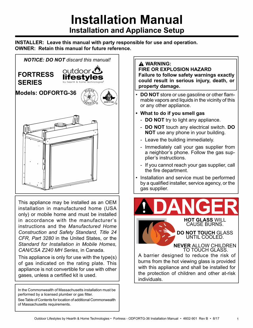
Installation ManualInstallation and Appliance Setup
INSTALLER: Leave this manual with party responsible for use and operation.OWNER: Retain this manual for future reference.
NOTICE: DO NOT discard this manual!
In the Commonwealth of Massachusetts installation must be performed by a licensed plumber or gas fitter.See Table of Contents for location of additional Commonwealth of Massachusetts requirements.
• DO NOT store or use gasoline or other flam-mable vapors and liquids in the vicinity of this or any other appliance.
• What to do if you smell gas - DO NOT try to light any appliance.- DO NOT touch any electrical switch. DO
NOT use any phone in your building.- Leave the building immediately.- Immediately call your gas supplier from
a neighbor’s phone. Follow the gas sup-plier’s instructions.
- If you cannot reach your gas supplier, call the fire department.
• Installation and service must be performed by a qualified installer, service agency, or the gas supplier.
WARNING: FIRE OR EXPLOSION HAZARDFailure to follow safety warnings exactly could result in serious injury, death, or property damage.
This appliance may be installed as an OEM installation in manufactured home (USA only) or mobile home and must be installed in accordance with the manufacturer’s instructions and the Manufactured Home Construction and Safety Standard, Title 24 CFR, Part 3280 in the United States, or the Standard for Installation in Mobile Homes, CAN/CSA Z240 MH Series, in Canada.This appliance is only for use with the type(s) of gas indicated on the rating plate. This appliance is not convertible for use with other gases, unless a certified kit is used.
DANGERHOT GLASS WILL CAUSE BURNS.
DO NOT TOUCH GLASS UNTIL COOLED.
NEVER ALLOW CHILDREN TO TOUCH GLASS.
A barrier designed to reduce the risk of burns from the hot viewing glass is provided with this appliance and shall be installed for the protection of children and other at-risk individuals.
Models: ODFORTG-36
FORTRESSSERIES
2 Outdoor Lifestyles by Hearth & Home Technologies • Fortress - ODFORTG-36 Installation Manual • 4602-901 Rev B • 8/17
Safety Alert Key:• DANGER! Indicates a hazardous situation which, if not avoided will result in death or serious injury.• WARNING! Indicates a hazardous situation which, if not avoided could result in death or serious injury.• CAUTION! Indicates a hazardous situation which, if not avoided, could result in minor or moderate injury.• NOTICE: Used to address practices not related to personal injury.
Table of Contents
Installation Standard Work Checklist . . . . . . . . . . . . . . . . . . . . 3
1 Product Specific and Important Safety Information A. Appliance Certification . . . . . . . . . . . . . . . . . . . . . . . . . . . . 4B. Glass Specifications . . . . . . . . . . . . . . . . . . . . . . . . . . . . . . 4C. BTU Specifications . . . . . . . . . . . . . . . . . . . . . . . . . . . . . . . 4D. High Altitude Installations . . . . . . . . . . . . . . . . . . . . . . . . . . 4E. Non-Combustible Materials Specification. . . . . . . . . . . . . . 4F. Combustible Materials Specification . . . . . . . . . . . . . . . . . 4G. Electrical Codes . . . . . . . . . . . . . . . . . . . . . . . . . . . . . . . . . 4H. Requirements for the Commonwealth of Massachusetts . . 5
2 Getting Started A. Design and Installation Considerations . . . . . . . . . . . . . . . 6B. Good Faith Wall Surface/TV Guidelines . . . . . . . . . . . . . . 6C. Tools and Supplies Needed . . . . . . . . . . . . . . . . . . . . . . . . 6D. Inspect Appliance and Components . . . . . . . . . . . . . . . . . . 7
3 Framing and Clearances A. Appliance/Decorative Front Dimension Diagrams . . . . . . . 8B. Clearances to Combustibles. . . . . . . . . . . . . . . . . . . . . . . . 9C. Mantel Combustibles. . . . . . . . . . . . . . . . . . . . . . . . . . . . . . 9D. Constructing the Appliance Chase . . . . . . . . . . . . . . . . . . 10E. Hearth Extension . . . . . . . . . . . . . . . . . . . . . . . . . . . . . . . 11
4 Termination Location and Vent Information A. Vent Termination Minimum Clearances . . . . . . . . . . . . . . 12B. Chimney Diagram. . . . . . . . . . . . . . . . . . . . . . . . . . . . . . . 13C. Approved Pipe . . . . . . . . . . . . . . . . . . . . . . . . . . . . . . . . . 14D. Use of Elbows . . . . . . . . . . . . . . . . . . . . . . . . . . . . . . . . . 15E. Measuring Standards . . . . . . . . . . . . . . . . . . . . . . . . . . . . 16F. Vent Diagrams . . . . . . . . . . . . . . . . . . . . . . . . . . . . . . . . . 16
5 Venting Installation A. Installation Precautions . . . . . . . . . . . . . . . . . . . . . . . . . . . 17B. Installation Planning . . . . . . . . . . . . . . . . . . . . . . . . . . . . . 18C. Installation Instructions . . . . . . . . . . . . . . . . . . . . . . . . . . . 18
6 Appliance Preparation A. Securing and Leveling the Appliance . . . . . . . . . . . . . . . . 25
7 Venting and Chimneys A. Assemble Vent Sections . . . . . . . . . . . . . . . . . . . . . . . . . 26B. Assemble Slip Sections . . . . . . . . . . . . . . . . . . . . . . . . . . 27C. Secure the Vent Sections . . . . . . . . . . . . . . . . . . . . . . . . . 27D. Disassemble Vent Sections . . . . . . . . . . . . . . . . . . . . . . . 28E. Vertical Termination Requirements . . . . . . . . . . . . . . . . . . 28F. Horizontal Termination Requirements . . . . . . . . . . . . . . . 30
8 Electrical Information A. General Information . . . . . . . . . . . . . . . . . . . . . . . . . . . . . 31B. Wiring Requirements . . . . . . . . . . . . . . . . . . . . . . . . . . . . 32
9 Gas Information A. Fuel Conversion . . . . . . . . . . . . . . . . . . . . . . . . . . . . . . . . 33B. Gas Pressure . . . . . . . . . . . . . . . . . . . . . . . . . . . . . . . . . . 33C. Gas Connection . . . . . . . . . . . . . . . . . . . . . . . . . . . . . . . . 33D. High Altitude Installations . . . . . . . . . . . . . . . . . . . . . . . . . 33
10 Finishing - Final Installation A. Facing Material . . . . . . . . . . . . . . . . . . . . . . . . . . . . . . . . . 34B. Installation Instructions for Outdoor Side . . . . . . . . . . . . . 34
C. Log Placement Instructions . . . . . . . . . . . . . . . . . . . . . . . 40
11 Reference Materials A. Vent Components Diagrams . . . . . . . . . . . . . . . . . . . . . . 43B. Accessories . . . . . . . . . . . . . . . . . . . . . . . . . . . . . . . . . . . 50
= Contains updated information.
►
►
►
3Outdoor Lifestyles by Hearth & Home Technologies • Fortress - ODFORTG-36 Installation Manual • 4602-901 Rev B • 8/17
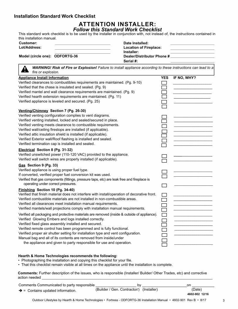
Installation Standard Work Checklist
Customer: Lot/Address:
Model (circle one): ODFORTG-36
Date Installed: Location of Fireplace:Installer:Dealer/Distributor Phone # Serial #:
Comments Communicated to party responsible ____________________ by ______________________on ___________ (Builder / Gen. Contractor/) (Installer) (Date) = Contains updated information.
Hearth & Home Technologies recommends the following:• Photographing the installation and copying this checklist for your file. • That this checklist remain visible at all times on the appliance until the installation is complete.
This standard work checklist is to be used by the installer in conjunction with, not instead of, the instructions contained in this installation manual.
WARNING! Risk of Fire or Explosion! Failure to install appliance according to these instructions can lead to a fire or explosion.
ATTENTION INSTALLER:Follow this Standard Work Checklist
Appliance Install Information YES IF NO, WHY?Verified clearances to combustibles requirements are maintained. (Pg. 9-10) ___________________ Verified that the chase is insulated and sealed. (Pg. 9) ___________________Verified mantel and wall clearance requirements are maintained. (Pg. 9) ___________________Verified hearth extension requirements are maintained. (Pg. 11) __________________Verified appliance is leveled and secured. (Pg. 25) ___________________
Venting/Chimney Section 7 (Pg. 26-30)Verified venting configuration complies to vent diagrams. ___________________Verified venting installed, locked and sealed/secured in place. ___________________Verified venting meets clearance to combustible requirements. ___________________Verified wall/ceiling firestops are installed (if applicable). ___________________Verified attic insulation shield is installed (if applicable). ___________________Verified Exterior wall/Roof flashing is installed and sealed. ___________________Verified termination cap is installed and sealed. ___________________Electrical Section 8 (Pg. 31-32) Verified unswitched power (110-120 VAC) provided to the appliance. ___________________Verified wall switch wires are properly installed (if applicable). ___________________Gas Section 9 (Pg. 33)Verified appliance is using proper fuel type. ___________________If converted, verified proper fuel conversion kit was used. ___________________Verified that gas components (fittings, pressure taps, etc) are leak free and fireplace is
operating under correct pressures. ___________________ Finishing Section 10 (Pg. 34-40)Verified that finish material does not interfere with install/operation of decorative front. ___________________Verified combustible materials are not installed in non-combustible areas. ___________________Verified all clearances meet installation manual requirements. ___________________Verified mantels/wall projections comply with installation manual requirements. ___________________Verified all packaging and protective materials are removed (inside & outside of appliance). ___________________Verified Glowing Embers and logs installed correctly. ___________________Verified fixed glass assembly installed and secured. ___________________Verified remote control has been programmed and is fully functional. ___________________Verified proper air shutter setting for installation type and vent configuration. ___________________Manual bag and all of its contents are removed from inside/under the appliance and given to party responsible for use and operation. ___________________
4602-902 12/16
Comments: Further description of the issues, who is responsible (Installer/ Builder/ Other Trades, etc) and corrective action needed ____________________________________________________________________________________
4 Outdoor Lifestyles by Hearth & Home Technologies • Fortress - ODFORTG-36 Installation Manual • 4602-901 Rev B • 8/17
B. Glass SpecificationsThis appliance is equipped with ceramic glass that is used on the inside glass door frames attached to the firebox. Replace glass only with ceramic glass. The out-door glass in the black frame screwed to the Stainless Steel frame is tempered glass. Replace with tempered glass. Please contact your dealer for replacement glass.
This product is listed to ANSI standards for “Vented Gas Fireplace Heaters” and applicable sections of “Gas Burn-ing Heating Appliances for Manufactured Homes and Recreational Vehicles”, and “Gas Fired Appliances for Use at High Altitudes”.
A. Appliance CertificationD. High Altitude InstallationsNOTICE: If the heating value of the gas has been reduced, these rules do not apply. Check with your local gas utility or authorities having jurisdiction.When installing above 2000 feet elevation:• In the USA: Reduce input rate 4% for each 1000 feet
above 2000 feet.
• In CANADA: Input ratings are certified without a reduction of input rate for elevations up to 4500 feet (1370 m) above sea level. Please consult provincial and/or local authorities having jurisdiction for installa- tions at elevations above 4500 feet (1370 m). Check with your local gas utility to determine proper orifice size.
E. Non-Combustible Materials SpecificationMaterial which will not ignite and burn. Such materials are those consisting entirely of steel, iron, brick, tile, concrete, slate, glass or plasters, or any combination thereof.Materials that are reported as passing ASTM E 136, Standard Test Method for Behavior of Materials in a Vertical Tube Furnace at 750 ºC shall be considered non-combustible materials.
F. Combustible Materials SpecificationMaterials made of or surfaced with wood, compressed pa-per, plant fibers, plastics, or other material that can ignite and burn, whether flame proofed or not, or plastered or unplastered shall be considered combustible materials.
G. Electrical CodesNOTICE: This appliance must be electrically wired and grounded in accordance with local codes or, in the absence of local codes, with National Electric Code ANSI/NFPA 70-latest edition or the Canadian Electric Code CSA C22.1.• A 110-120 VAC circuit for this product must be pro-
tected with ground-fault circuit-interrupter protection, in compliance with the applicable electrical codes, when it is installed in locations such as in bathrooms or near sinks.
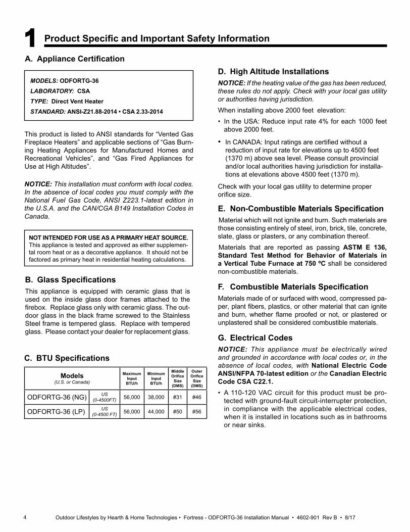
NOT INTENDED FOR USE AS A PRIMARY HEAT SOURCE. This appliance is tested and approved as either supplemen-tal room heat or as a decorative appliance. It should not be factored as primary heat in residential heating calculations.
NOTICE: This installation must conform with local codes. In the absence of local codes you must comply with the National Fuel Gas Code, ANSI Z223.1-latest edition in the U.S.A. and the CAN/CGA B149 Installation Codes in Canada.
1 Product Specific and Important Safety Information
MODELS: ODFORTG-36LABORATORY: CSATYPE: Direct Vent HeaterSTANDARD: ANSI-Z21.88-2014 • CSA 2.33-2014
C. BTU Specifications
Models(U.S. or Canada)
MaximumInput BTU/h
MinimumInput BTU/h
MiddleOrifice
Size (DMS)
OuterOrifice
Size (DMS)
ODFORTG-36 (NG) US(0-4500FT) 56,000 38,000 #31 #46
ODFORTG-36 (LP) US(0-4500 FT) 56,000 44,000 #50 #56
5Outdoor Lifestyles by Hearth & Home Technologies • Fortress - ODFORTG-36 Installation Manual • 4602-901 Rev B • 8/17
H. Requirements for the Commonwealth of Massachusetts
For all side wall horizontally vented gas fueled equipment installed in every dwelling, building or structure used in whole or in part for residential purposes, including those owned or operated by the Commonwealth and where the side wall exhaust vent termination is less than seven (7) feet above finished grade in the area of the venting, in-cluding but not limited to decks and porches, the following requirements shall be satisfied:
Installation of Carbon Monoxide DetectorsAt the time of installation of the side wall horizontal vented gas fueled equipment, the installing plumber or gas fitter shall observe that a hard wired carbon monoxide detector with an alarm and battery back-up is installed on the floor level where the gas equipment is to be installed. In addi-tion, the installing plumber or gas fitter shall observe that a battery operated or hard wired carbon monoxide detec-tor with an alarm is installed on each additional level of the dwelling, building or structure served by the side wall horizontal vented gas fueled equipment. It shall be the responsibility of the property owner to secure the services of qualified licensed professionals for the installation of hard wired carbon monoxide detectors.
In the event that the side wall horizontally vented gas fu-eled equipment is installed in a crawl space or an attic, the hard wired carbon monoxide detector with alarm and battery back-up may be installed on the next adjacent floor level.In the event that the requirements of this subdivision can not be met at the time of completion of installation, the owner shall have a period of thirty (30) days to comply with the above requirements; provided, however, that dur-ing said thirty (30) day period, a battery operated carbon monoxide detector with an alarm shall be installed.
Approved Carbon Monoxide DetectorsEach carbon monoxide detector as required in accor-dance with the above provisions shall comply with NFPA 720 and be ANSI/UL 2034 listed and IAS certified.
SignageA metal or plastic identification plate shall be permanent-ly mounted to the exterior of the building at a minimum height of eight (8) feet above grade directly in line with the exhaust vent terminal for the horizontally vented gas fu-eled heating appliance or equipment. The sign shall read, in print size no less than one-half (1/2) in. in size, “GAS VENT DIRECTLY BELOW. KEEP CLEAR OF ALL OB-STRUCTIONS”.
InspectionThe state or local gas inspector of the side wall horizon-tally vented gas fueled equipment shall not approve the installation unless, upon inspection, the inspector ob-serves carbon monoxide detectors and signage installed in accordance with the provisions of 248 CMR 5.08(2)(a)1 through 4.
ExemptionsThe following equipment is exempt from 248 CMR 5.08(2)(a)1 through 4: • The equipment listed in Chapter 10 entitled “Equipment
Not Required To Be Vented” in the most current edition of NFPA 54 as adopted by the Board; and
• Product Approved side wall horizontally vented gas fu-eled equipment installed in a room or structure separate from the dwelling, building or structure used in whole or in part for residential purposes.
MANUFACTURER REQUIREMENTS
Gas Equipment Venting System ProvidedWhen the manufacturer of Product Approved side wall horizontally vented gas equipment provides a venting system design or venting system components with the equipment, the instructions provided by the manufacturer for installation of the equipment and the venting system shall include:• Detailed instructions for the installation of the venting
system design or the venting system components; and• A complete parts list for the venting system design or
venting system.
Gas Equipment Venting System NOT ProvidedWhen the manufacturer of a Product Approved side wall horizontally vented gas fueled equipment does not pro-vide the parts for venting the flue gases, but identifies “special venting systems”, the following requirements shall be satisfied by the manufacturer:
• The referenced “special venting system” instructions shall be included with the appliance or equipment in-stallation instructions; and
• The “special venting systems” shall be Product Ap-proved by the Board, and the instructions for that sys-tem shall include a parts list and detailed installation instructions.
A copy of all installation instructions for all Product Ap-proved side wall horizontally vented gas fueled equip-ment, all venting instructions, all parts lists for venting instructions, and/or all venting design instructions shall remain with the appliance or equipment at the completion of the installation.
See Gas Connection section for additional Common-wealth of Massachusetts requirements.
Note: The following requirements reference various Massachusetts and national codes not contained in this document.
6 Outdoor Lifestyles by Hearth & Home Technologies • Fortress - ODFORTG-36 Installation Manual • 4602-901 Rev B • 8/17
2 Getting Started
A. Design and Installation ConsiderationsOutdoor Lifestyles direct vent gas appliances are de-signed to operate with all combustion air siphoned from outside of the building and all exhaust gases expelled to the outside. No additional outside air source is required.Installation MUST comply with local, regional, state and national codes and regulations. Consult insurance carrier, local building inspector, fire officials or authorities having jurisdiction over restrictions, installation inspection and permits.Before installing, determine the following:• Where the appliance is to be installed.• The vent system configuration to be used.• Gas supply piping requirements.• Electrical wiring requirements.• Framing and finishing details. • Whether optional accessories—devices such a wall
switch or remote control—are desired.
C. Tools and Supplies NeededBefore beginning the installation be sure that the following tools and building supplies are available.Tape measure Framing materialPliers Hammer Phillips screwdriver ManometerGloves Framing squareVoltmeter Electric drill and bits (1/4 in.)Plumb line Safety glassesLevel Reciprocating sawFlat blade screwdriverNon-corrosive leak check solution1/2 - 3/4 in. length, #6 or #8 Self-drilling screwsCaulking material (300 ºF minimum continuous exposure rating)One 1/4 in. female connection (for optional fan).
Improper installation, adjustment, alteration, service or maintenance can cause injury or property damage. For assistance or additional information, consult a qualified service technician, service agency or your dealer.
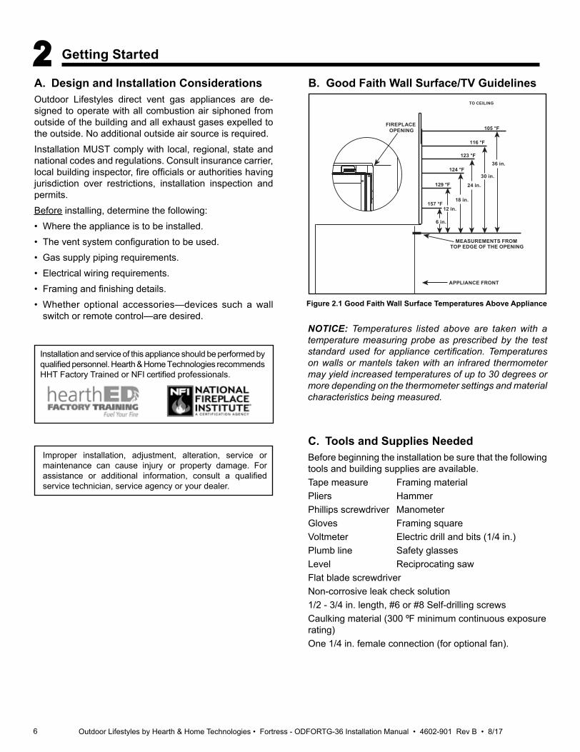
Figure 2.1 Good Faith Wall Surface Temperatures Above Appliance
B. Good Faith Wall Surface/TV Guidelines
NOTICE: Temperatures listed above are taken with a temperature measuring probe as prescribed by the test standard used for appliance certification. Temperatures on walls or mantels taken with an infrared thermometer may yield increased temperatures of up to 30 degrees or more depending on the thermometer settings and material characteristics being measured.
MEASUREMENTS FROMTOP EDGE OF THE OPENING
6 in.
18 in.
24 in.
30 in.
36 in.
TO CEILING
12 in.
APPLIANCE FRONT
FIREPLACE OPENING
157 °F
129 °F
124 °F
123 °F
116 °F
105 °F
Installation and service of this appliance should be performed by qualified personnel. Hearth & Home Technologies recommends HHT Factory Trained or NFI certified professionals.

7Outdoor Lifestyles by Hearth & Home Technologies • Fortress - ODFORTG-36 Installation Manual • 4602-901 Rev B • 8/17
D. Inspect Appliance and Components• Carefully remove the appliance and components from
the packaging. • The vent system components may be shipped in
separate packages. • If packaged separately, the log set and appliance grate
must be installed. • Report to your dealer any parts damaged in shipment,
particularly the condition of the glass. • Read all of the instructions before starting the instal-
lation. Follow these instructions carefully during the installation to ensure maximum safety and benefit.
WARNING! Risk of Fire or Explosion! Damaged parts could impair safe operation. DO NOT install damaged, in-complete or substitute components. Keep appliance dry.
Hearth & Home Technologies disclaims any responsibility for, and the warranty will be voided by, the following actions:
• Installation and use of any damaged appliance or vent system component.
• Modification of the appliance or vent system.
• Installation other than as instructed by Hearth & Home Technologies.
• Improper positioning of the gas logs or the glass door.
• Installation and/or use of any component part not approved by Hearth & Home Technologies.
Any such action may cause a fire hazard.
WARNING! Risk of Fire, Explosion or Electric Shock! DO NOT use this appliance if any part has been under water. Call a qualified service technician to inspect the appliance and to replace any part of the control system and/or gas control which has been under water.

8 Outdoor Lifestyles by Hearth & Home Technologies • Fortress - ODFORTG-36 Installation Manual • 4602-901 Rev B • 8/17
3 Framing and Clearances
A. Appliance/Decorative Front Dimension DiagramsDimensions are actual appliance dimensions. Use for reference only. For framing dimensions and clearances refer to Section 5.
Figure 3.1 Appliance Dimensions
Location Inches MillimetersG 7-3/8 187H 9 228I 12 305J 23-13/16 605K 24 609L 25-5/8 650
Location Inches MillimetersA 471/2 1207B 39-3/8 1000C 34-1/4 869D 38-1/4 978E 49-3/8 1254F 44-3/8 1128
J
I
E
F
D C
K
L
B
A
H
G
Appliance Dimensions Table
9Outdoor Lifestyles by Hearth & Home Technologies • Fortress - ODFORTG-36 Installation Manual • 4602-901 Rev B • 8/17
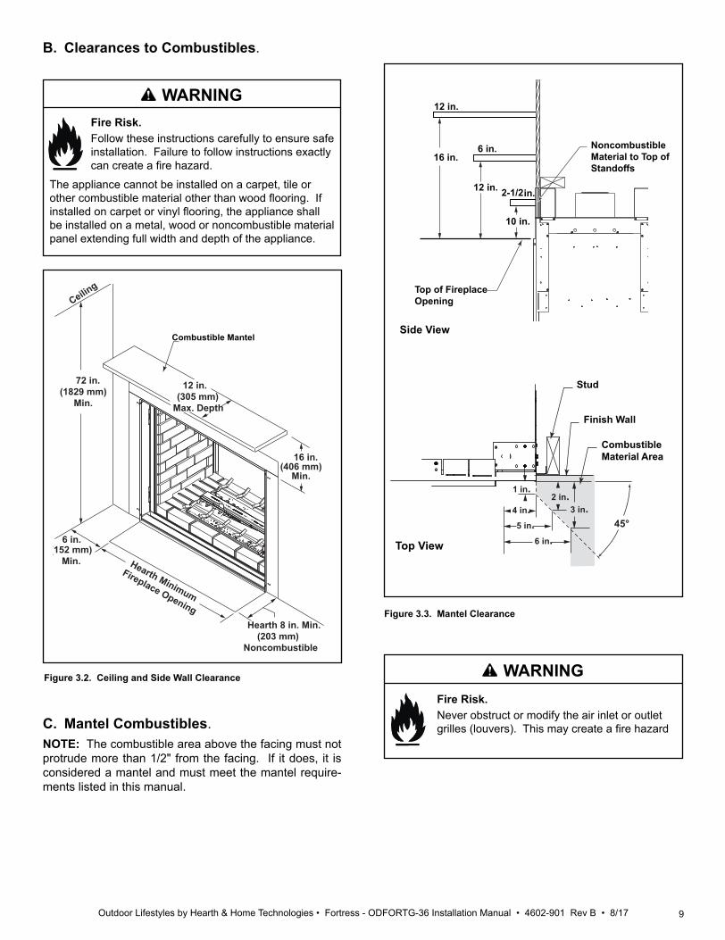
B. Clearances to Combustibles.
Fire Risk. Follow these instructions carefully to ensure safe installation. Failure to follow instructions exactly can create a fire hazard.
WARNING
The appliance cannot be installed on a carpet, tile or other combustible material other than wood flooring. If installed on carpet or vinyl flooring, the appliance shall be installed on a metal, wood or noncombustible material panel extending full width and depth of the appliance.
72 in.(1829 mm)
Min.
Ceiling
12 in.(305 mm)
Max. Depth
16 in.(406 mm)
Min.
6 in.(152 mm)
Min.
Hearth 8 in. Min.(203 mm)
Noncombustible
Hearth Minimum
Fireplace Opening
Combustible Mantel
Figure 3.2. Ceiling and Side Wall Clearance
C. Mantel Combustibles.NOTE: The combustible area above the facing must not protrude more than 1/2" from the facing. If it does, it is considered a mantel and must meet the mantel require-ments listed in this manual.
45°
1 in.
4 in.
Stud
Finish Wall
Combustible Material Area
Top View
5 in.6 in.
2 in.3 in.
16 in.
12 in.
10 in.
12 in.
6 in.
2-1/2 in.
Side View
Noncombustible Material to Top of Standoffs
Top of Fireplace Opening
Figure 3.3. Mantel Clearance
Fire Risk. Never obstruct or modify the air inlet or outlet grilles (louvers). This may create a fire hazard
WARNING

10 Outdoor Lifestyles by Hearth & Home Technologies • Fortress - ODFORTG-36 Installation Manual • 4602-901 Rev B • 8/17
D. Constructing the Appliance ChaseA chase is a vertical box-like structure built to enclose the gas appliance and/or its vent system. In cooler climates the vent should be enclosed inside the chase.NOTICE: Treatment of ceiling firestops and wall shield firestops and construction of the chase may vary with the type of building. These instructions are not substitutes for the requirements of local building codes. Therefore, you MUST check local building codes to determine the requirements to these steps.Chases should be constructed in the manner of all out-side walls of the home to prevent cold air drafting prob-lems. The chase should not break the outside building envelope in any manner.Walls, ceiling, base plate and cantilever floor of the chase should be insulated. Vapor and air infiltration barriers should be installed in the chase as per regional codes for the rest of the home. Additionally, in regions where cold air infiltration may be an issue, the inside surfaces may be sheetrocked and taped (or an equivalent method may be used) to achieve maximum air tightness.
NOTICE: Install appliance on hard metal or wood surfaces extending full width and depth. DO NOT install directly on carpeting, vinyl, tile or any combustible material other than wood.WARNING! Risk of Fire! Maintain specified air space clearances to appliance and vent pipe:• Insulation and other materials must be secured to prevent
accidental contact.• The chase must be properly blocked to prevent blown
insulation or other combustibles from entering and making contact with fireplace or chimney.
• Failure to maintain airspace may cause overheating and a fire.
To further prevent drafts, the wall shield and ceiling fire-stops should be caulked with caulk with a minimum of 300 ºF continuous exposure rating to seal gaps. Gas line holes and other openings should be caulked with caulk with a minimum of 300 ºF continuous exposure rating or stuffed with unfaced insulation. If the appliance is being installed on a cement surface, a layer of plywood may be placed underneath to prevent conducting cold up into the room.
Figure 3.4 Clearances to Combustibles
F
E=33 in.
G
H
I
E=43 in.
MINIMUM FRAMING DIMENSIONS*A B** C* D E F** G** H I
RoughOpening
(Vent Pipe)
RoughOpening(Height)
RoughOpening(Depth)
RoughOpening(Width)
Clearanceto ceiling
from opening
Clearanceto ceiling
from top of appliance
CombustibleFloor
CombustibleFlooring
Sides of Appliance
Front or Rear of Appli-ance
Inches 10 44-1/2 23 49-1/2 37-3/4 33-1/2 0 See Note Below 1 48
Millime-ters 254 1130 584 1257 959 851 0 See Note Below 25 1219
* Adjust framing dimensions for interior sheathing (such as sheetrock)** Fireplace may need to be elevated from the floor affecting framing height B, depending on hearth construction. See Section 3.D for hearth and combustible floor requirements.
C
A
B
D
HEADERDEPTH** HEADER
DEPTH**
APPLIANCE MAY BE INSTALLED OFF OF FLOOR***
►
11Outdoor Lifestyles by Hearth & Home Technologies • Fortress - ODFORTG-36 Installation Manual • 4602-901 Rev B • 8/17
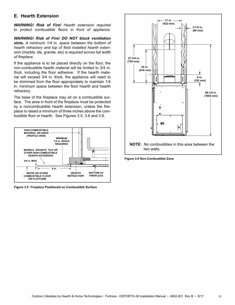
E. Hearth Extension
WARNING! Risk of Fire! Hearth extension required to protect combustible floors in front of appliance.
WARNING! Risk of Fire! DO NOT block ventilation slots. A minimum 1/4 in. space between the bottom of hearth refractory and top of field installed hearth exten-sion (marble, tile, granite, etc) is required across full width of fireplace.If the appliance is to be placed directly on the floor, the non-combustible hearth material will be limited to 3/4 in. thick, including the floor adhesive. If the hearth mate-rial will exceed 3/4 in. thick, the appliance will need to be shimmed from the floor appropriately to maintain 1/4 in. minimum space between the floor hearth and hearth refractory. The base of the fireplace may sit on a combustible sur-face. The area in front of the fireplace must be protected by a noncombustible hearth extension, unless the fire-place is raised a minimum of three inches above the com-bustible floor or hearth. See Figures 3.5, 3.6 and 3.8.
Figure 3.6 Non-Combustible Zone
Figure 3.5 Fireplace Positioned on Combustible Surface
17 in.(432 mm)
3-1/2 in. (89 mm)
27-3/4 in. (705 mm)
24 in. (610 mm)
6 in. (152 mm)
66-1/4 in. (1683 mm)
WOOD OR OTHER COMBUSTIBLE FLOOR
OR PLATFORM
MARBLE, GRANITE, TILE OR OTHER NON-COMBUSTIBLE
HEARTH EXTENSION
3/4 in. MAX
8 in.
HEARTH REFRACTORY
BOTTOM OF FIREPLACE
NON-COMBUSTIBLE MATERIAL ON SIDES
(PROFILE VIEW)MINIMUM
1/4 in. SPACE REQUIRED NOTE: No combustibles in this area between the
two walls.

12 Outdoor Lifestyles by Hearth & Home Technologies • Fortress - ODFORTG-36 Installation Manual • 4602-901 Rev B • 8/17
A. Vent Termination Minimum Clearances
Roof Pitch H (Min.) Ft.Flat to 6/12...........................................................1.0*Over 6/12 to 7/12 .................................................1.25*Over 7/12 to 8/12 .................................................1.5*Over 8/12 to 9/12 .................................................2.0*Over 9/12 to 10/12 ...............................................2.5*Over 10/12 to 11/12 .............................................3.25Over 11/12 to 12/12 .............................................4.0Over 12/12 to 14/12 .............................................5.0Over 14/12 to 16/12 .............................................6.0Over 16/12 to 18/12 .............................................7.0Over 18/12 to 20/12 .............................................7.5Over 20/12 to 21/12 .............................................8.0
Figure 4.1 Minimum Height From Roof to Lowest Discharge Opening
HORIZONTALOVERHANG
VERTICALWALL
GAS DIRECT VENT TERMINATION CAP
12X
ROOF PITCHIS X/ 12
LOWEST DISCHARGE
OPENING
2 ft.MIN.
20 in. MIN.
H (MIN.) - MINIMUM HEIGHT FROM ROOFTO LOWEST DISCHARGE OPENING
4 Termination Location and Vent Information
Fire Risk.Maintain vent clearance to combustibles as specified.• DO NOT pack air space with insulation or other
materials.Failure to keep insulation or other materials away from vent pipe could cause overheating and fire.
WARNING
Figure 4.2 Staggered Termination Caps
Gas, Wood or Fuel OilTermination Cap
B
GasTermination
Cap **
A *
* If using decorative cap cover(s), this distance may need to be increased. Refer to the installation instructions supplied with the decorative cap cover.
**
A B6 in. (minimum) up to 20 in.
152 mm/508 mm18 in. minimum
457 mm20 in. and over 0 in. minimum
In a staggered installation with both gas and wood or fuel oil terminations, the wood or fuel oil termination cap must be higher than the gas termination cap.
* H minimum may vary depending on regional snowfall. Refer to local codes.

13Outdoor Lifestyles by Hearth & Home Technologies • Fortress - ODFORTG-36 Installation Manual • 4602-901 Rev B • 8/17
Figure 4.3 Minimum Clearances for Termination
ON
P
R
Q
X = AIR SUPPLY INLET
A = 12 inches.................clearances above grade, veranda, porch, deck or balcony
B = 12 inches. ................clearance to window or door that may be opened, or to permanently closed window
C = 18 inches .................clearance below unventilated soffit 18 inches.................clearance below ventilated soffit 30 inches ................clearance below vinyl soffits and
electrical service D = 6 inches...................clearance to outside cornerE = 6 inches...................clearance to inside cornerF = 3 ft. (Canada) ..........not to be installed above a gas me-
ter/regulator assembly within 3 feet horizontally from the center-line of the regulator
G = 3 ft ...........................clearance to gas service regulator vent outlet
H = 12 inches.................clearance to non-mechanical (unpow-ered) air supply inlet, combustion air inlet or direct-vent termination
i = 3 ft. (U.S.A.) 6 ft. (Canada) ...........clearance to a mechanical (powered)
air supply inlet
All mechanical air intakes within 10 feet of a termination cap must be a minimum of 3 feet below termination.
J = 7 ft. ......................... On public property: clearance above paved sidewalk or a paved driveway.
A vent shall not terminate directly above a sidewalk or paved driveway which is located between two single family dwellings and serves both dwellings.
V = VENT TERMINAL
= AREA WHERE TERMINAL IS NOT PERMITTED
C
J B
D
B
F
B
A
EV
V
VV
V
V
M
H or i
VG
X
V HA
VV
H
Electrical Service
V
KV K
V
L
C
V
N = 6 inches ........... non-vinyl sidewalls 12 inches ......... vinyl sidewallsO = 18 inches ......... non-vinyl soffit and overhang 42 inches ......... vinyl soffit and overhangP = 8 ft.
QMIN RMAX
1 cap 3 feet 2 x Q ACTUAL
2 caps 6 feet 1 x Q ACTUAL
3 caps 9 feet 2/3 x Q ACTUAL
4 caps 12 feet 1/2 x Q ACTUAL
QMIN = # termination caps x 3 RMAX = (2 / # termination caps) x QACTUAL
Covered Alcove Applications (Spaces open only on one side and with an overhang)
Measure horizontal clearances from this surface.
Measure vertical clearances from this surface.
CLEARANCE = 6 IN.
CAUTION! Risk of Burns! Termination caps are HOT, consider proximity to doors, traffic areas or where people may pass or gather (sidewalk, deck, patio, etc.). Listed cap shields available. Contact your dealer.• Local codes or regulations may require different
clearances.• Vent system termination is NOT permitted in screened
porches.• Vent system termination is permitted in porch areas with
two or more sides open. • Hearth & Home Technologies assumes no responsibility
for the improper performance of the appliance when the venting system does not meet these requirements.
• Vinyl protection kits are suggested for use with vinyl siding.
M = 6 inches ....................clearance under veranda, porch, deck, balcony or overhang
12 inches.................vinyl or composite overhangPermitted when veranda, porch, deck or balcony is fully open on a minimum of 2 sides beneath the floor.
K = 6 inches................. clearance from sides of electrical service
L = 12 inches................ clearance above electrical serviceLocation of the vent termination must not interfere with access to the electrical service.
B. Chimney Diagram
14 Outdoor Lifestyles by Hearth & Home Technologies • Fortress - ODFORTG-36 Installation Manual • 4602-901 Rev B • 8/17
C. Approved PipeThis appliance is approved for use with Hearth & Home Technologies DVP venting systems. SLP venting may be used when a power vent is installed. Refer to Section 11.A for vent component information and dimensions.DO NOT mix pipe, fittings or joining methods from differ-ent manufacturers.The pipe is tested to be run inside an enclosed wall. There is no requirement for inspection openings at each joint within the wall.WARNING! Risk of Fire or Asphyxiation. This appli-ance requires a separate vent. DO NOT vent to a pipe serving a separate solid fuel burning appliance.
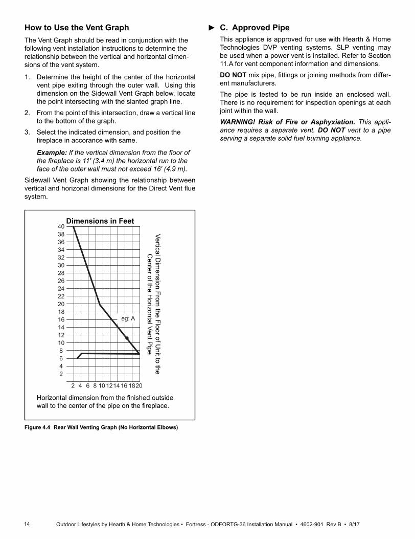
How to Use the Vent GraphThe Vent Graph should be read in conjunction with the following vent installation instructions to determine the relationship between the vertical and horizontal dimen-sions of the vent system.
1. Determine the height of the center of the horizontal vent pipe exiting through the outer wall. Using this dimension on the Sidewall Vent Graph below, locate the point intersecting with the slanted graph line.
2. From the point of this intersection, draw a vertical line to the bottom of the graph.
3. Select the indicated dimension, and position the fireplace in accorance with same. Example: If the vertical dimension from the floor of the fireplace is 11' (3.4 m) the horizontal run to the face of the outer wall must not exceed 16' (4.9 m).
Sidewall Vent Graph showing the relationship between vertical and horizonal dimensions for the Direct Vent flue system.
Figure 4.4 Rear Wall Venting Graph (No Horizontal Elbows)
403836343230282624222018161412108642
2 4 6 8 10 12 14 16 18 20
eg: A
Dimensions in Feet
Vertical Dim
ension From the Floor of U
nit to the C
enter of the Horizontal Vent P
ipe
Horizontal dimension from the finished outside wall to the center of the pipe on the fireplace.
►
15Outdoor Lifestyles by Hearth & Home Technologies • Fortress - ODFORTG-36 Installation Manual • 4602-901 Rev B • 8/17
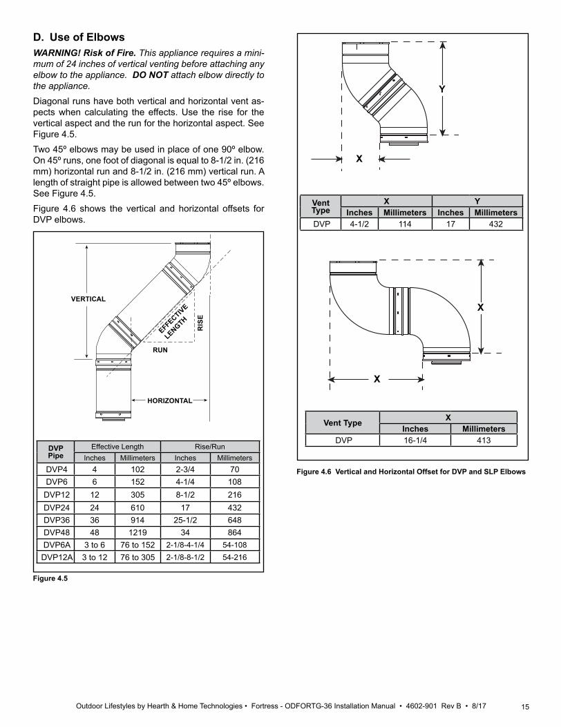
D. Use of ElbowsWARNING! Risk of Fire. This appliance requires a mini-mum of 24 inches of vertical venting before attaching any elbow to the appliance. DO NOT attach elbow directly to the appliance.Diagonal runs have both vertical and horizontal vent as-pects when calculating the effects. Use the rise for the vertical aspect and the run for the horizontal aspect. See Figure 4.5.Two 45º elbows may be used in place of one 90º elbow. On 45º runs, one foot of diagonal is equal to 8-1/2 in. (216 mm) horizontal run and 8-1/2 in. (216 mm) vertical run. A length of straight pipe is allowed between two 45º elbows. See Figure 4.5.Figure 4.6 shows the vertical and horizontal offsets for DVP elbows.
Figure 4.5
HORIZONTAL
VERTICAL
RUN
RIS
E
EFFECTIVE
LENGTH
DVPPipe
Effective Length Rise/RunInches Millimeters Inches Millimeters
DVP4 4 102 2-3/4 70DVP6 6 152 4-1/4 108DVP12 12 305 8-1/2 216DVP24 24 610 17 432DVP36 36 914 25-1/2 648DVP48 48 1219 34 864DVP6A 3 to 6 76 to 152 2-1/8-4-1/4 54-108DVP12A 3 to 12 76 to 305 2-1/8-8-1/2 54-216
Y
X
X
X
Vent Type XInches Millimeters
DVP 16-1/4 413
Figure 4.6 Vertical and Horizontal Offset for DVP and SLP Elbows
Vent Type
X YInches Millimeters Inches Millimeters
DVP 4-1/2 114 17 432
16 Outdoor Lifestyles by Hearth & Home Technologies • Fortress - ODFORTG-36 Installation Manual • 4602-901 Rev B • 8/17
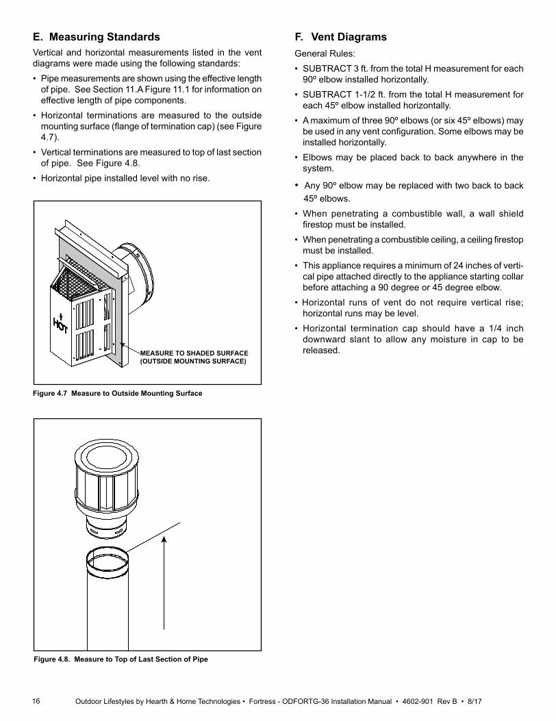
E. Measuring StandardsVertical and horizontal measurements listed in the vent diagrams were made using the following standards:• Pipe measurements are shown using the effective length
of pipe. See Section 11.A Figure 11.1 for information on effective length of pipe components.
• Horizontal terminations are measured to the outside mounting surface (flange of termination cap) (see Figure 4.7).
• Vertical terminations are measured to top of last section of pipe. See Figure 4.8.
• Horizontal pipe installed level with no rise.
MEASURE TO SHADED SURFACE (OUTSIDE MOUNTING SURFACE)
Figure 4.7 Measure to Outside Mounting Surface
Figure 4.8. Measure to Top of Last Section of Pipe
General Rules:• SUBTRACT 3 ft. from the total H measurement for each
90º elbow installed horizontally.• SUBTRACT 1-1/2 ft. from the total H measurement for
each 45º elbow installed horizontally.• A maximum of three 90º elbows (or six 45º elbows) may
be used in any vent configuration. Some elbows may be installed horizontally.
• Elbows may be placed back to back anywhere in the system.
• Any 90º elbow may be replaced with two back to back 45º elbows.
• When penetrating a combustible wall, a wall shield firestop must be installed.
• When penetrating a combustible ceiling, a ceiling firestop must be installed.
• This appliance requires a minimum of 24 inches of verti-cal pipe attached directly to the appliance starting collar before attaching a 90 degree or 45 degree elbow.
• Horizontal runs of vent do not require vertical rise; horizontal runs may be level.
• Horizontal termination cap should have a 1/4 inch downward slant to allow any moisture in cap to be released.
F. Vent Diagrams
17Outdoor Lifestyles by Hearth & Home Technologies • Fortress - ODFORTG-36 Installation Manual • 4602-901 Rev B • 8/17
Read all instructions completely and thoroughly before attemping installation. Falilure to do so could result in serious injury, property damage or loss of life. Operation of improperly installed and maintained venting system could result in serious injury, property damage or loss of life.
WARNING
A. Installation Precautions
Consult local building codes before beginning the instal-lation. The installer must make sure to select the proper vent system for installation. Before installing vent kit, the installer must read this fireplace manual and vent kit instructions.
Only a qualified installer/service person should install the venting system. The installer must follow these safety rules: • Wear gloves and safety glass for protection.• Use extreme caution when using ladders or when on
rooftops. • Be aware of electrical wiring locations in walls and
ceilings. The following actions will void the warranty on your venting system:
• Installation of any damaged venting component.• Unauthorized modification of the venting system. • Installation of any component part not manufactured or
approved by Hearth & Home Technologies. • Installation other than permitted by these instructions.
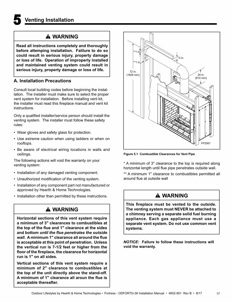
Horizontal sections of this vent system require a minimum of 3" clearances to combustibles at the top of the flue and 1" clearance at the sides and bottom until the flue penetrates the outside wall. A minimum 1" clearance all around the flue is acceptable at this point of penetration. Unless the vertical run is 7-1/2 feet or higher from the floor of the fireplace, the clearance for horizontal run is 1" on all sides. Vertical sections of this vent system require a minimum of 2" clearance to combustibles at the top of the unit directly above the stand-off. A minimum of 1" clearance all aroun the flue is acceptable thereafter.
WARNING
NOTICE: Failure to follow these instructions will void the warranty.
*3 in.
**1 in.
**1 in.
FP2567KSTDV vent clearances
24 in.(610 mm)
72 in.(1829 mm)
Figure 5.1 Combustible Clearances for Vent Pipe
* A minimum of 3" clearance to the top is required along horizontal length until flue pipe penetrates outside wall. ** A minimum 1" clearance to combustibles permitted all around flue at outside wall
FP2567
WARNINGThis fireplace must be vented to the outside. The venting system must NEVER be attached to a chimney serving a separate solid fuel burning appliance. Each gas appliance must use a separate vent system. Do not use common vent systems.
5 Venting Installation

18 Outdoor Lifestyles by Hearth & Home Technologies • Fortress - ODFORTG-36 Installation Manual • 4602-901 Rev B • 8/17
B. Installation Planning
There are two basic types of direct-vent installation:
• Horizontal Termination • Vertical Termination
It is important to select the proper length of vent pipe for the type of termination you choose. It is also important to note the wall thickness.
For Horizontal Termination
Select the amount of vertical rise desired. All horizontal run of venting must have 1/4" rise for every 12" of run towards the termination below 71⁄2" of vertical rise from floor of fire-place. With 71⁄2 feet or more of vertical rise from the floor of the fireplace, the horizontal run may be level. NEVER run vent piping down.You may use up to three 90° elbows in this vent configura-tion. Refer to Vertical/Horizontal Termination Configurations on Page 20.
For Vertical Termination
Measure the distance from the fireplace floor to the ceil-ing. Add the ceiling thickness, the vertical rise in an attic or second story, and allow for sufficient vent height above the roof line.
NOTE: You may use two 45° elbows in place of a 90° elbow. You must follow rise to run ratios when using 45° elbows. The appliance is approved for use with three 90° elbows maximum or a combination of 90° and 45° elbows up to a maximum of 270°.
NOTICE: When installing in a chase, you should insulate the chase as you would the outside walls of your home. This is especially important in cold climates. Insulation should be considered a combustible material. Maintain proper clearances to all combustible materials.
NOTICE: Treatment of firestops and construction of the chase may vary from building type to building type. These instructions are not substitutes for the requirements of local building codes. You must follow all local building codes.
Never run the vent pipe down. This may cause excessive temperatures which could cause a fire.
For two-story applications, firestops are required at each floor level. If an offset is needed in the attic, additional pipe and elbows will be required.You may use a chase with a vent termination with exposed pipe on the exterior of the house. See Installing Vent System in a Chase below. If pipe is enclosed in chase, it is not exposed. It is very important that the venting system maintain its bal-ance between the combustion air intake and the flue gas exhaust. Certain limitations apply to vent configurations and must be strictly followed.
C. Installation Instructions
Installing a Vent System in an Outside Chase
A chase is a vertical boxlike structure built to enclose venting that runs along the outside of a building. A chase is required for such venting.
WARNING
Always maintain minimum clearances around vent systems. The minimum clearances to combustibles for horizontal vent pipe are 3” at the top* and 1” at the sides and bottom of the vent system until the pipe penetrates the nearest vertical wall (1” required). A 1” minimum clearance all around the pipe must be maintained at outside wall and on vertical runs. Do not pack the open air spaces with insulation or other materials. This could cause high temperatures and may present a fire hazard. *Unless the vertical run is 71⁄2 feet or higher from floor of fireplace, the clearance for the horizontal run is 1” on all sides.
WARNING
19Outdoor Lifestyles by Hearth & Home Technologies • Fortress - ODFORTG-36 Installation Manual • 4602-901 Rev B • 8/17
Vertical Sidewall Installation
NOTE: Sealant is not required to assemble fireplace venting. Do not use silicone sealant at the inner flue exhaust connections.
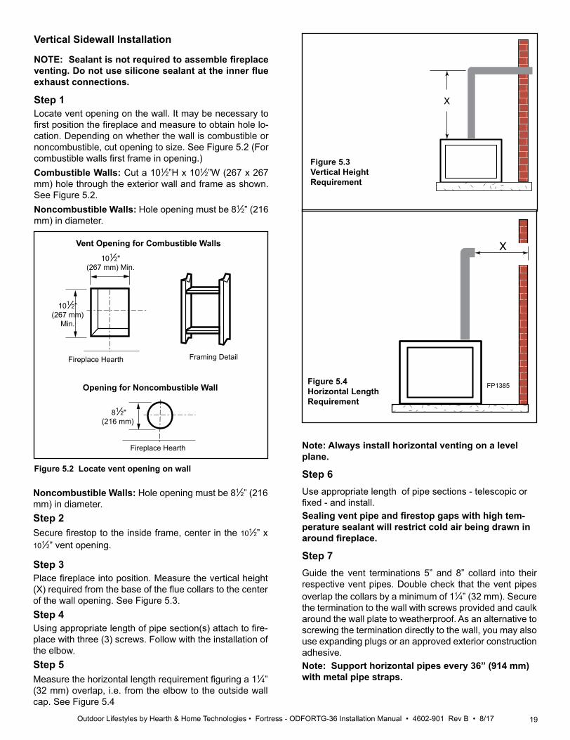
Step 1Locate vent opening on the wall. It may be necessary to first position the fireplace and measure to obtain hole lo-cation. Depending on whether the wall is combustible or noncombustible, cut opening to size. See Figure 5.2 (For combustible walls first frame in opening.)Combustible Walls: Cut a 101⁄2”H x 101⁄2”W (267 x 267 mm) hole through the exterior wall and frame as shown. See Figure 5.2.Noncombustible Walls: Hole opening must be 81⁄2” (216 mm) in diameter.
Figure 5.4 Horizontal Length Requirement
Noncombustible Walls: Hole opening must be 81⁄2” (216 mm) in diameter.Step 2Secure firestop to the inside frame, center in the 101⁄2” x 101⁄2” vent opening.
Step 3Place fireplace into position. Measure the vertical height (X) required from the base of the flue collars to the center of the wall opening. See Figure 5.3.Step 4Using appropriate length of pipe section(s) attach to fire-place with three (3) screws. Follow with the installation of the elbow. Step 5Measure the horizontal length requirement figuring a 11⁄4” (32 mm) overlap, i.e. from the elbow to the outside wall cap. See Figure 5.4
X X
X
X
FP1385
VO584-100Vent Opening2/99 djt
101⁄2”(267 mm)
Min.
Fireplace Hearth
Opening for Noncombustible Wall
81⁄2"(216 mm)
Fireplace Hearth
Figure 5.2 Locate vent opening on wall
101⁄2"(267 mm) Min.
Vent Opening for Combustible Walls
Framing Detail
Note: Always install horizontal venting on a level plane.
Step 6 Use appropriate length of pipe sections - telescopic or fixed - and install. Sealing vent pipe and firestop gaps with high tem-perature sealant will restrict cold air being drawn in around fireplace. Step 7Guide the vent terminations 5” and 8” collard into their respective vent pipes. Double check that the vent pipes overlap the collars by a minimum of 11⁄4” (32 mm). Secure the termination to the wall with screws provided and caulk around the wall plate to weatherproof. As an alternative to screwing the termination directly to the wall, you may also use expanding plugs or an approved exterior construction adhesive. Note: Support horizontal pipes every 36” (914 mm) with metal pipe straps.
Figure 5.3 Vertical Height Requirement
20 Outdoor Lifestyles by Hearth & Home Technologies • Fortress - ODFORTG-36 Installation Manual • 4602-901 Rev B • 8/17
Vertical/Horizontal Termination configurationsSince it is very important that the venting system maintain its balance between the combustion air intake and the flue gas exhaust, certain limitations as to vent configurations apply and must be strictly adhered to.The Vent Graph, showing the relationship between vertical and horizontal side wall venting, will help to determine the various dimensions allowable. See Figure 4.4.NOTE: Horizontal sections of this vent system require a minimum of 3" clearances to combustibles at the top of the flue and 1" clearance at the sides and bottom until the flue penetrates the outside wall. A minimum 1" clearance all around the flue is acceptable at this point of penetration. Unless the vertical run is 71⁄2 feet or higher from floor of fireplace, the clearance for the horizontal run is 1" on all sides.Vertical sections of this vent system require a minimum of 1" clearance to combustibles on all sides of the pipe. When vent exits through foundations less than 20" below outcrop, the termination must be flush up with outcropped wall above.It is best to locate the fireplace in such a way that minimizes the number of offsets and horizontal vent length.The horizontal vent run refers to the total length of vent pipe from the flue collar of the fireplace (or the top of the Transition Elbow) to the face of the finished outside wall.
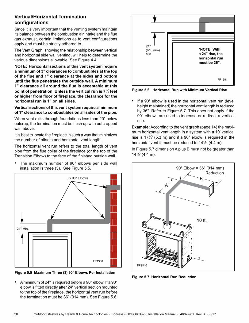
• The maximum number of 90° elbows per side wall installation is three (3). See Figure 5.5.
Figure 5.5 Maximum Three (3) 90° Elbows Per Installation
3 x 90° Elbows
24" Min.
FP1380
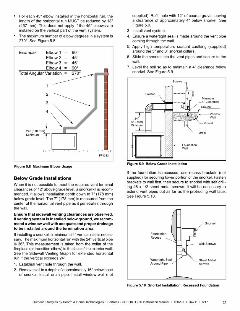
• If a 90° elbow is used in the horizontal vent run (level height maintained) the horizontal vent length is reduced by 36". Refer to Figure 5.7. This does not apply if the 90° elbows are used to increase or redirect a vertical rise.
Example: According to the vent graph (page 14) the maxi-mum horizontal vent length in a system with a 10' vertical rise is 171⁄2’ (5.3 m) and if a 90° elbow is required in the horizontal vent it must be reduced to 141⁄2' (4.4 m). In Figure 5.7 dimension A plus B must not be greater than 141⁄2' (4.4 m).
AB
10 ft.
FP2546Horizontal run reduction
Figure 5.7 Horizontal Run Reduction
FP2546
• A minimum of 24" is required before a 90° elbow. If a 90° elbow is fitted directly after 24" vertical section mounted to the top of the fireplace, the horizontal vent run before the termination must be 36” (914 mm). See Figure 5.6.
Max. 20"(508mm)
36"(914mm)
FP1381
Figure 5.6 Horizontal Run with Minimum Vertical Rise
*NOTE: With a 24" rise, the horizontal run must be 36".
24"(610 mm)Min.
90° Elbow = 36" (914 mm) Reduction
21Outdoor Lifestyles by Hearth & Home Technologies • Fortress - ODFORTG-36 Installation Manual • 4602-901 Rev B • 8/17
1
2
3
4
1
2
3
4
FP1383Max bends
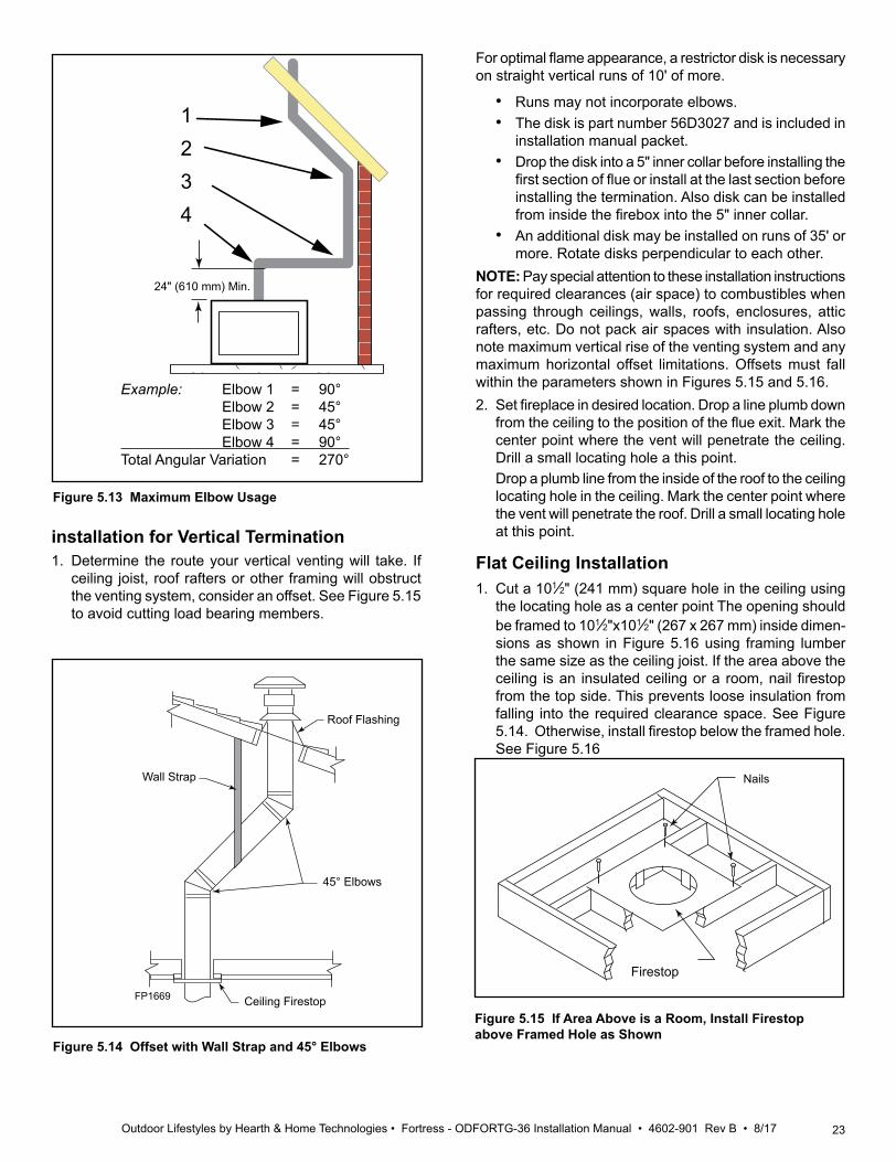
Example: Elbow 1 = 90° Elbow 2 = 45° Elbow 3 = 45° Elbow 4 = 90°Total Angular Variation = 270°
Figure 5.8 Maximum Elbow Usage
24" (610 mm)Minimum
FP1383
supplied). Refill hole with 12" of coarse gravel leaving a clearance of approximately 4" below snorkel. See Figure 5.9.
3. Install vent system.4. Ensure a watertight seal is made around the vent pipe
coming through the wall.5. Apply high temperature sealant caulking (supplied)
around the 5" and 8" snorkel collars.6. Slide the snorkel into the vent pipes and secure to the
wall.7. Level the soil so as to maintain a 4" clearance below
snorkel. See Figure 5.9.
Figure 5.9 Below Grade Installation
FP2134below grade install
Screws
Minimum 4" Clearance
Ground
Window Well
Gravel
Drain
Foundation Wall
Firestop
24" (610 mm)Minimum
• For each 45° elbow installed in the horizontal run, the length of the horizontal run MUST be reduced by 18" (457 mm). This does not apply if the 45° elbows are installed on the vertical part of the vent system.
• The maximum number of elbow degrees in a system is 270°. See Figure 5.8.
Below Grade InstallationsWhen it is not possible to meet the required vent terminal clearances of 12" above grade level, a snorkel kit is recom-mended. It allows installation depth down to 7" (178 mm) below grade level. The 7" (178 mm) is measured from the center of the horizontal vent pipe as it penetrates through the wall.Ensure that sidewall venting clearances are observed. If venting system is installed below ground, we recom-mend a window well with adequate and proper drainage to be installed around the termination area.If installing a snorkel, a minimum 24" vertical rise is neces-sary. The maximum horizontal run with the 24” vertical pipe is 36". This measurement is taken from the collar of the fireplace (or transition elbow) to the face of the exterior wall. See the Sidewall Venting Graph for extended horizontal run if the vertical exceeds 24".1. Establish vent hole through the wall. 2. Remove soil to a depth of approximately 16" below base
of snorkel. Install drain pipe. Install window well (not
If the foundation is recessed, use recess brackets (not supplied) for securing lower portion of the snorkel. Fasten brackets to wall first, then secure to snorkel with self drill-ing #8 x 1/2 sheet metal screws. It will be necessary to extend vent pipes out as far as the protruding wall face. See Figure 5.10.
Figure 5.10 Snorkel Installation, Recessed Foundation
FP1966snorkel
FoundationRecess
Watertight Seal Around Pipe
Sheet Metal Screws
Wall Screws
Snorkel
22 Outdoor Lifestyles by Hearth & Home Technologies • Fortress - ODFORTG-36 Installation Manual • 4602-901 Rev B • 8/17
• Do not back fill around snorkel.• A clearance of at least 4" must be
maintained between the snorkel and the soil.
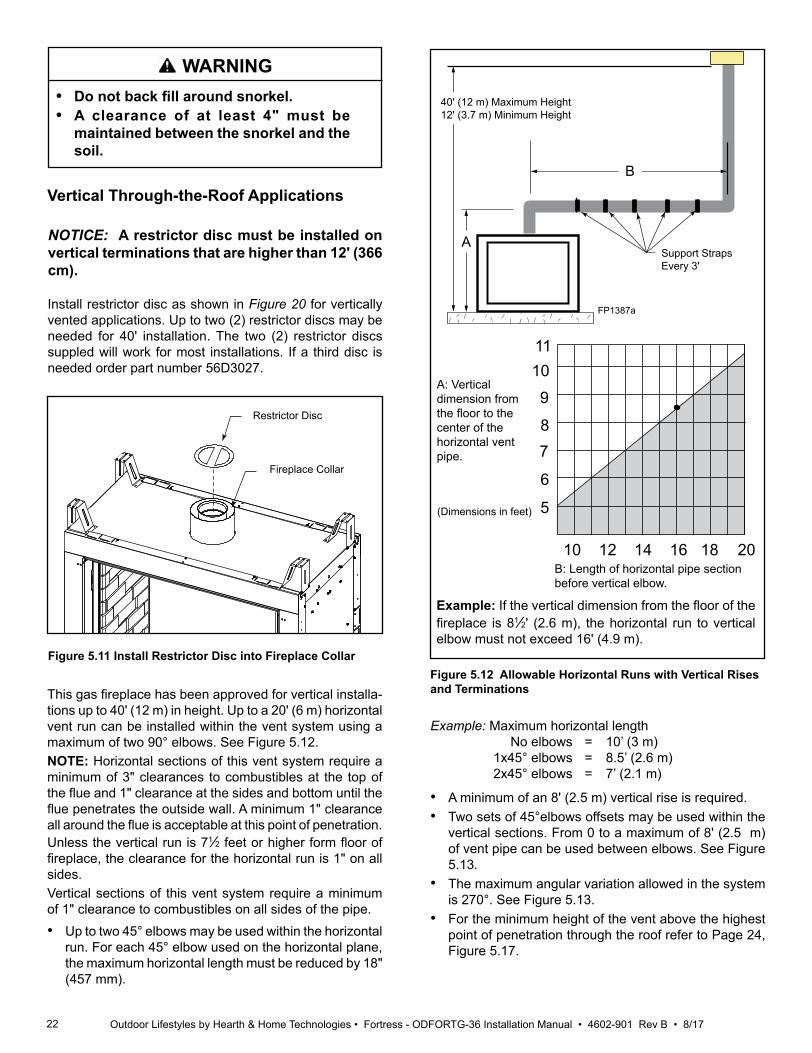
Install restrictor disc as shown in Figure 20 for vertically vented applications. Up to two (2) restrictor discs may be needed for 40' installation. The two (2) restrictor discs suppled will work for most installations. If a third disc is needed order part number 56D3027.
Vertical Through-the-Roof Applications
NOTICE: A restrictor disc must be installed on vertical terminations that are higher than 12' (366 cm).
FP2707restrictor disc
Restrictor Disc
Fireplace Collar
Figure 5.11 Install Restrictor Disc into Fireplace Collar
This gas fireplace has been approved for vertical installa-tions up to 40' (12 m) in height. Up to a 20' (6 m) horizontal vent run can be installed within the vent system using a maximum of two 90° elbows. See Figure 5.12.NOTE: Horizontal sections of this vent system require a minimum of 3" clearances to combustibles at the top of the flue and 1" clearance at the sides and bottom until the flue penetrates the outside wall. A minimum 1" clearance all around the flue is acceptable at this point of penetration. Unless the vertical run is 71⁄2 feet or higher form floor of fireplace, the clearance for the horizontal run is 1" on all sides.Vertical sections of this vent system require a minimum of 1" clearance to combustibles on all sides of the pipe.• Up to two 45° elbows may be used within the horizontal
run. For each 45° elbow used on the horizontal plane, the maximum horizontal length must be reduced by 18" (457 mm).
B
A
40' (12 m) Maximum Height12' (3.7 m) Minimum Height
Support StrapsEvery 3'
FP1387a
Figure 5.12 Allowable Horizontal Runs with Vertical Rises and Terminations
10 12 14 16 18 20
5
6
78
9
1011
FP2917vert horiz vent graph
A: Vertical dimension from the floor to the center of the horizontal vent pipe.
B: Length of horizontal pipe section before vertical elbow.
(Dimensions in feet)
Example: If the vertical dimension from the floor of the fireplace is 81⁄2' (2.6 m), the horizontal run to vertical elbow must not exceed 16' (4.9 m).
Example: Maximum horizontal length No elbows = 10’ (3 m) 1x45° elbows = 8.5’ (2.6 m) 2x45° elbows = 7’ (2.1 m)
• A minimum of an 8' (2.5 m) vertical rise is required.• Two sets of 45°elbows offsets may be used within the
vertical sections. From 0 to a maximum of 8' (2.5 m) of vent pipe can be used between elbows. See Figure 5.13.
• The maximum angular variation allowed in the system is 270°. See Figure 5.13.
• For the minimum height of the vent above the highest point of penetration through the roof refer to Page 24, Figure 5.17.
WARNING
23Outdoor Lifestyles by Hearth & Home Technologies • Fortress - ODFORTG-36 Installation Manual • 4602-901 Rev B • 8/17
1
2
3
4
1
2
3
4
FP1179max bends
Example: Elbow 1 = 90° Elbow 2 = 45° Elbow 3 = 45° Elbow 4 = 90°Total Angular Variation = 270°
24" (610 mm) Min.
Figure 5.13 Maximum Elbow Usage
installation for Vertical Termination1. Determine the route your vertical venting will take. If
ceiling joist, roof rafters or other framing will obstruct the venting system, consider an offset. See Figure 5.15 to avoid cutting load bearing members.
Figure 5.14 Offset with Wall Strap and 45° Elbows FP1969offset w/ wallstrap
Roof Flashing
Wall Strap
45° Elbows
Ceiling Firestop FP1669
For optimal flame appearance, a restrictor disk is necessary on straight vertical runs of 10' of more.
• Runs may not incorporate elbows. • The disk is part number 56D3027 and is included in
installation manual packet.• Drop the disk into a 5" inner collar before installing the
first section of flue or install at the last section before installing the termination. Also disk can be installed from inside the firebox into the 5" inner collar.
• An additional disk may be installed on runs of 35' or more. Rotate disks perpendicular to each other.
NOTE: Pay special attention to these installation instructions for required clearances (air space) to combustibles when passing through ceilings, walls, roofs, enclosures, attic rafters, etc. Do not pack air spaces with insulation. Also note maximum vertical rise of the venting system and any maximum horizontal offset limitations. Offsets must fall within the parameters shown in Figures 5.15 and 5.16.2. Set fireplace in desired location. Drop a line plumb down
from the ceiling to the position of the flue exit. Mark the center point where the vent will penetrate the ceiling. Drill a small locating hole a this point.
Drop a plumb line from the inside of the roof to the ceiling locating hole in the ceiling. Mark the center point where the vent will penetrate the roof. Drill a small locating hole at this point.
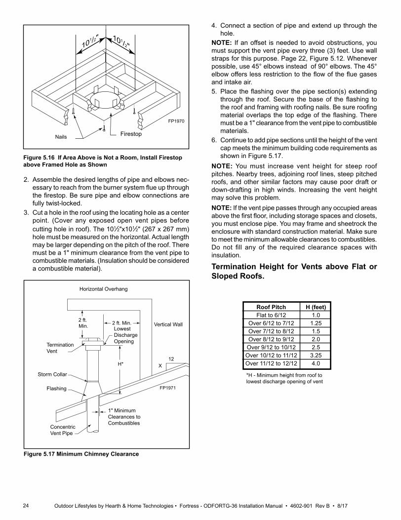
Flat Ceiling Installation1. Cut a 101⁄2" (241 mm) square hole in the ceiling using
the locating hole as a center point The opening should be framed to 101⁄2"x101⁄2" (267 x 267 mm) inside dimen-sions as shown in Figure 5.16 using framing lumber the same size as the ceiling joist. If the area above the ceiling is an insulated ceiling or a room, nail firestop from the top side. This prevents loose insulation from falling into the required clearance space. See Figure 5.14. Otherwise, install firestop below the framed hole. See Figure 5.16
Figure 5.15 If Area Above is a Room, Install Firestop above Framed Hole as Shown
FP1969firestop w room above
Firestop
Nails
24 Outdoor Lifestyles by Hearth & Home Technologies • Fortress - ODFORTG-36 Installation Manual • 4602-901 Rev B • 8/17
2. Assemble the desired lengths of pipe and elbows nec-essary to reach from the burner system flue up through the firestop. Be sure pipe and elbow connections are fully twist-locked.
3. Cut a hole in the roof using the locating hole as a center point. (Cover any exposed open vent pipes before cutting hole in roof). The 101⁄2"x101⁄2" (267 x 267 mm) hole must be measured on the horizontal. Actual length may be larger depending on the pitch of the roof. There must be a 1" minimum clearance from the vent pipe to combustible materials. (Insulation should be considered a combustible material).
4. Connect a section of pipe and extend up through the hole.
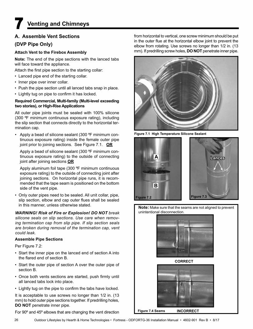
NOTE: If an offset is needed to avoid obstructions, you must support the vent pipe every three (3) feet. Use wall straps for this purpose. Page 22, Figure 5.12. Whenever possible, use 45° elbows instead of 90° elbows. The 45° elbow offers less restriction to the flow of the flue gases and intake air.5. Place the flashing over the pipe section(s) extending
through the roof. Secure the base of the flashing to the roof and framing with roofing nails. Be sure roofing material overlaps the top edge of the flashing. There must be a 1" clearance from the vent pipe to combustible materials.
6. Continue to add pipe sections until the height of the vent cap meets the minimum building code requirements as shown in Figure 5.17.
NOTE: You must increase vent height for steep roof pitches. Nearby trees, adjoining roof lines, steep pitched roofs, and other similar factors may cause poor draft or down-drafting in high winds. Increasing the vent height may solve this problem.NOTE: If the vent pipe passes through any occupied areas above the first floor, including storage spaces and closets, you must enclose pipe. You may frame and sheetrock the enclosure with standard construction material. Make sure to meet the minimum allowable clearances to combustibles. Do not fill any of the required clearance spaces with insulation.
Termination Height for Vents above Flat or Sloped Roofs.
Figure 5.16 If Area Above is Not a Room, Install Firestop above Framed Hole as Shown
101/2"101/2"
FP1970firestop no room
Nails Firestop
FP1970
2 ft. Min. 2 ft. Min.
X12
H*
FP1971Min chimney clearance
Horizontal Overhang
Termination Vent
Lowest Discharge Opening
Storm Collar
Flashing
Concentric Vent Pipe
1" Minimum Clearances to Combustibles
Vertical Wall
FP1971
Figure 5.17 Minimum Chimney Clearance
Roof Pitch H (feet) Flat to 6/12 1.0 Over 6/12 to 7/12 1.25 Over 7/12 to 8/12 1.5 Over 8/12 to 9/12 2.0 Over 9/12 to 10/12 2.5 Over 10/12 to 11/12 3.25 Over 11/12 to 12/12 4.0
*H - Minimum height from roof to lowest discharge opening of vent

25Outdoor Lifestyles by Hearth & Home Technologies • Fortress - ODFORTG-36 Installation Manual • 4602-901 Rev B • 8/17
6 Appliance Preparation
A. Securing and Leveling the ApplianceWARNING! Risk of Fire! Prevent contact with:
• Sagging or loose insulation• Insulation backing or plastic• Framing and other combustible materialsBlock openings into the chase to prevent entry of blown-in insulation. Make sure insulation and other materials are secured.DO NOT notch the framing around the appliance standoffs.Failure to maintain air space clearance may cause overheating and fire.
The diagram shows how to properly position and secure the appliance. See Figure 6.1. Nailing tabs are provided to secure the appliance to the framing members.• Bend out nailing tabs on each side.• Place the appliance into position.• Keep nailing tabs flush with the framing.• Level the appliance from side to side and front to back.• Shim the appliance as necessary. It is acceptable to use
wood shims underneath the appliance.• Secure the appliance to the framing by using nails or
screws through the nailing tabs.• Secure the appliance to the floor by inserting two screws
through the pilot holes at the bottom of the appliance. • Optional: Secure the appliance to the floor by inserting
two screws through the pilot holes at the bottom of the appliance.
Figure 6.1 Proper positioning, leveling and securing of an appliance
26 Outdoor Lifestyles by Hearth & Home Technologies • Fortress - ODFORTG-36 Installation Manual • 4602-901 Rev B • 8/17
7 Venting and Chimneys
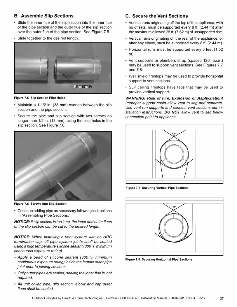
A. Assemble Vent Sections (DVP Pipe Only)Attach Vent to the Firebox AssemblyNote: The end of the pipe sections with the lanced tabs will face toward the appliance.Attach the first pipe section to the starting collar:• Lanced pipe end of the starting collar.• Inner pipe over inner collar.• Push the pipe section until all lanced tabs snap in place.• Lightly tug on pipe to confirm it has locked.
Figure 7.2
A
B
Figure 7.3
Assemble Pipe SectionsPer Figure 7.2:• Start the inner pipe on the lanced end of section A into
the flared end of section B.• Start the outer pipe of section A over the outer pipe of
section B.• Once both vents sections are started, push firmly until
all lanced tabs lock into place.• Lightly tug on the pipe to confirm the tabs have locked.It is acceptable to use screws no longer than 1/2 in. (13 mm) to hold outer pipe sections together. If predrilling holes, DO NOT penetrate inner pipe.For 90º and 45º elbows that are changing the vent direction
Required Commercial, Multi-family (Multi-level exceeding two stories), or High-Rise ApplicationsAll outer pipe joints must be sealed with 100% silicone (300 ºF minimum continuous exposure rating), including the slip section that connects directly to the horizontal ter-mination cap. • Apply a bead of silicone sealant (300 ºF minimum con-
tinuous exposure rating) inside the female outer pipe joint prior to joining sections. See Figure 7.1. OR
Apply a bead of silicone sealant (300 ºF minimum con-tinuous exposure rating) to the outside of connecting joint after joining sections OR
Apply aluminum foil tape (300 ºF minimum continuous exposure rating) to the outside of connecting joint after joining sections. On horizontal pipe runs, it is recom-mended that the tape seam is positioned on the bottom side of the vent pipe.
• Only outer pipes need to be sealed. All unit collar, pipe, slip section, elbow and cap outer flues shall be sealed in this manner, unless otherwise stated.
WARNING! Risk of Fire or Explosion! DO NOT break silicone seals on slip sections. Use care when remov-ing termination cap from slip pipe. If slip section seals are broken during removal of the termination cap, vent could leak.
Figure 7.4 Seams
Note: Make sure that the seams are not aligned to prevent unintentional disconnection.
INCORRECT
CORRECT
Lances
Figure 7.1 High Temperature Silicone Sealant
from horizontal to vertical, one screw minimum should be put in the outer flue at the horizontal elbow joint to prevent the elbow from rotating. Use screws no longer than 1/2 in. (13 mm). If predrilling screw holes, DO NOT penetrate inner pipe.
27Outdoor Lifestyles by Hearth & Home Technologies • Fortress - ODFORTG-36 Installation Manual • 4602-901 Rev B • 8/17
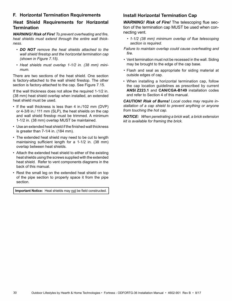
B. Assemble Slip Sections• Slide the inner flue of the slip section into the inner flue
of the pipe section and the outer flue of the slip section over the outer flue of the pipe section. See Figure 7.5.
• Slide together to the desired length.
Figure 7.5 Slip Section Pilot Holes
Figure 7.6 Screws into Slip Section
Pilot hole
• Continue adding pipe as necessary following instructions in “Assembling Pipe Sections.”
NOTICE: If slip section is too long, the inner and outer flues of the slip section can be cut to the desired length.
• Maintain a 1-1/2 in. (38 mm) overlap between the slip section and the pipe section.
• Secure the pipe and slip section with two screws no longer than 1/2 in. (13 mm), using the pilot holes in the slip section. See Figure 7.6.
NOTICE: When installing a vent system with an HRC termination cap, all pipe system joints shall be sealed using a high temperature silicone sealant (300 ºF minimum continuous exposure rating). • Apply a bead of silicone sealant (300 ºF minimum
continuous exposure rating) inside the female outer pipe joint prior to joining sections.
• Only outer pipes are sealed, sealing the inner flue is not required.
• All unit collar, pipe, slip section, elbow and cap outer flues shall be sealed.
120º
Figure 7.7 Securing Vertical Pipe Sections
C. Secure the Vent Sections• Vertical runs originating off the top of the appliance, with
no offsets, must be supported every 8 ft. (2.44 m) after the maximum allowed 25 ft. (7.62 m) of unsupported rise.
• Vertical runs originating off the rear of the appliance, or after any elbow, must be supported every 8 ft. (2.44 m).
• Horizontal runs must be supported every 5 feet (1.52 m).
• Vent supports or plumbers strap (spaced 120º apart) may be used to support vent sections. See Figures 7.7 and 7.8.
• Wall shield firestops may be used to provide horizontal support to vent sections.
• SLP ceiling firestops have tabs that may be used to provide vertical support.
WARNING! Risk of Fire, Explosion or Asphyxiation! Improper support could allow vent to sag and separate. Use vent run supports and connect vent sections per in-stallation instructions. DO NOT allow vent to sag below connection point to appliance.
120º
Figure 7.8 Securing Horizontal Pipe Sections

28 Outdoor Lifestyles by Hearth & Home Technologies • Fortress - ODFORTG-36 Installation Manual • 4602-901 Rev B • 8/17
D. Disassemble Vent Sections• Rotate either section (see Figure 7.9) so the seams on
both pipe sections are aligned as shown in Figure 7.10. • Pull carefully to separate the pieces of pipe.
Figure 7.10 Align and Disassemble Vent Sections
Figure 7.9 Rotate Seams for Disassembly
E. Vertical Termination RequirementsInstall Metal Roof Flashing• See minimum vent heights for various pitched roofs
(Figure 7.11) to determine the length of pipe to extend through the roof.
• Slide the roof flashing over the pipe sections extending through the roof as shown in Figure 7.12.
Roof Pitch H (Min.) Ft.Flat to 6/12........................................1.0*Over 6/12 to 7/12 ............................1.25*Over 7/12 to 8/12 ..............................1.5*Over 8/12 to 9/12 ..............................2.0*Over 9/12 to 10/12 ............................2.5*Over 10/12 to 11/12 ......................... 3.25Over 11/12 to 12/12 ........................... 4.0Over 12/12 to 14/12 ........................... 5.0Over 14/12 to 16/12 ........................... 6.0Over 16/12 to 18/12 ........................... 7.0Over 18/12 to 20/12 ........................... 7.5Over 20/12 to 21/12 ........................... 8.0* H minimum may vary depending on regional snowfall. Refer to local codes.
Figure 7.11 Minimum Height From Roof to Lowest Discharge Opening
HORIZONTALOVERHANG
VERTICALWALL
GAS DIRECT VENT TERMINATION CAP
12X
ROOF PITCHIS X/ 12
LOWEST DISCHARGE
OPENING
2 ft.MIN.
20 in. MIN.
H (MIN.) - MINIMUM HEIGHT FROM ROOFTO LOWEST DISCHARGE OPENING
NOTICE: Failure to properly caulk the roof flashing and pipe seams could permit entry of water.• Caulk the gap between the roof flashing and the outside
diameter of the pipe. • Caulk the perimeter of the flashing where it contacts the
roof surface. See Figure 7.13.• Caulk the overlap seam of any exposed pipe sections
that are located above the roof line.

29Outdoor Lifestyles by Hearth & Home Technologies • Fortress - ODFORTG-36 Installation Manual • 4602-901 Rev B • 8/17
Figure 7.13 insert Bolt into Brackets
CAULK
Figure 7.12
Assemble and Install Storm CollarCAUTION! Risk of Cuts, Abrasions or Flying Debris. Wear protective gloves and safety glasses during instal-lation. Sheet metal edges are sharp.• Slide the storm collar onto the exposed pipe section
and align brackets.• Insert a bolt (provided) through the brackets and install
nut. Do not completely tighten.
• Slide the assembled storm collar down the pipe section until it rests on the roof flashing (see Figure 7.13).
• Tighten nut and make sure the collar is tight against the pipe section.
• Caulk around the top of the storm collar. See Figure 7.14.
Install Vertical Termination Cap• Attach the vertical termination cap by sliding the inner
collar of the cap into the inner flue of the pipe section while placing the outer collar of the cap over the outer flue of the pipe section.
• Secure the cap by driving three self-tapping screws (supplied) through the pilot holes in the outer collar of the cap into the outer flue of the pipe (see Figure 7.14).
Figure 7.14
30 Outdoor Lifestyles by Hearth & Home Technologies • Fortress - ODFORTG-36 Installation Manual • 4602-901 Rev B • 8/17
Install Horizontal Termination Cap WARNING! Risk of Fire! The telescoping flue sec-tion of the termination cap MUST be used when con-necting vent.
• 1-1/2 (38 mm) minimum overlap of flue telescoping section is required.
Failure to maintain overlap could cause overheating and fire.
• Vent termination must not be recessed in the wall. Siding may be brought to the edge of the cap base.
• Flash and seal as appropriate for siding material at outside edges of cap.
• When installing a horizontal termination cap, follow the cap location guidelines as prescribed by current ANSI Z223.1 and CAN/CGA-B149 installation codes and refer to Section 4 of this manual.
CAUTION! Risk of Burns! Local codes may require in-stallation of a cap shield to prevent anything or anyone from touching the hot cap.NOTICE: When penetrating a brick wall, a brick extension kit is available for framing the brick.
Important Notice: Heat shields may not be field constructed.
F. Horizontal Termination RequirementsHeat Shield Requirements for Horizontal TerminationWARNING! Risk of Fire! To prevent overheating and fire, heat shields must extend through the entire wall thick-ness.
• DO NOT remove the heat shields attached to the wall shield firestop and the horizontal termination cap (shown in Figure 7.15).
• Heat shields must overlap 1-1/2 in. (38 mm) mini-mum.
There are two sections of the heat shield. One section is factory-attached to the wall shield firestop. The other section is factory-attached to the cap. See Figure 7.15.If the wall thickness does not allow the required 1-1/2 in. (38 mm) heat shield overlap when installed, an extended heat shield must be used.• If the wall thickness is less than 4 in./102 mm (DVP)
or 4-3/8 in./ 111 mm (SLP), the heat shields on the cap and wall shield firestop must be trimmed. A minimum 1-1/2 in. (38 mm) overlap MUST be maintained.
• Use an extended heat shield if the finished wall thickness is greater than 7-1/4 in. (184 mm).
• The extended heat shield may need to be cut to length maintaining sufficient length for a 1-1/2 in. (38 mm) overlap between heat shields.
• Attach the extended heat shield to either of the existing heat shields using the screws supplied with the extended heat shield. Refer to vent components diagrams in the back of this manual.
• Rest the small leg on the extended heat shield on top of the pipe section to properly space it from the pipe section.

31Outdoor Lifestyles by Hearth & Home Technologies • Fortress - ODFORTG-36 Installation Manual • 4602-901 Rev B • 8/17
A. General InformationWARNING! Risk of Shock or Explosion! DO NOT wire 110-120 VAC to the valve or to the appliance wall switch. Incorrect wiring will damage controls.NOTICE: This appliance must be electrically wired and grounded in accordance with local codes or, in the absence of local codes, with National Electric Code ANSI/NFPA 70-latest edition or the Canadian Electric Code CSA C22.1.• Wire the appliance junction box to unswitched 110-
120 VAC. This is required for proper operation of the appliance (Intellifire ignition).
• A 110-120 VAC circuit for this product must be protected with ground-fault circuit-interrupter protection, in compliance with the applicable electrical codes, when it is installed in locations such as in bathrooms or near sinks.
• Low voltage and 110-120 VAC voltage cannot be shared within the same wall box.
Accessories Requirements• This appliance may be used with a wall switch, wall
mounted thermostat and/or a remote control.Wiring for optional Hearth & Home Technologies approved accessories should be done now to avoid reconstruction. Follow instructions that come with those accessories.
8 Electrical Information
Electrical Service and RepairWARNING! Risk of Shock! Label all wires prior to dis-connection when servicing controls. Wiring errors could cause improper and dangerous operation. Verify proper operation after servicing.
WARNING! Risk of Shock! Replace damaged wire with type 105º C rated wire. Wire must have high temperature insulation.
Junction Box Installation• Pull the electrical wires from outside the appliance through
the opening into the valve compartment and secure wires with a Romex connector. See Figure 8.1.
• Make all necessary wire connections to the junction box/receptacle and reattach the junction box/receptacle to the outer shell.
Figure 8.1 Junction Box Detail
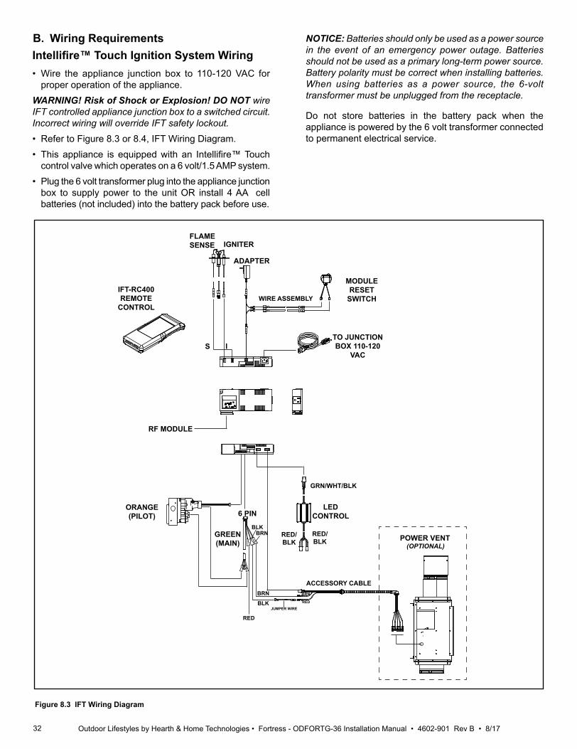
32 Outdoor Lifestyles by Hearth & Home Technologies • Fortress - ODFORTG-36 Installation Manual • 4602-901 Rev B • 8/17
B. Wiring RequirementsIntellifire™ Touch Ignition System Wiring
NOTICE: Batteries should only be used as a power source in the event of an emergency power outage. Batteries should not be used as a primary long-term power source. Battery polarity must be correct when installing batteries. When using batteries as a power source, the 6-volt transformer must be unplugged from the receptacle.
Do not store batteries in the battery pack when the appliance is powered by the 6 volt transformer connected to permanent electrical service.
• Wire the appliance junction box to 110-120 VAC for proper operation of the appliance.
WARNING! Risk of Shock or Explosion! DO NOT wire IFT controlled appliance junction box to a switched circuit. Incorrect wiring will override IFT safety lockout.• Refer to Figure 8.3 or 8.4, IFT Wiring Diagram.• This appliance is equipped with an Intellifire™ Touch
control valve which operates on a 6 volt/1.5 AMP system.• Plug the 6 volt transformer plug into the appliance junction
box to supply power to the unit OR install 4 AA cell batteries (not included) into the battery pack before use.
Figure 8.3 IFT Wiring Diagram
FLAME SENSE IGNITER
TO JUNCTION BOX 110-120
VAC
LED CONTROL
RF MODULE
ADAPTER
IS
6 PIN
RED
BLK
ORANGE(PILOT)
GREEN(MAIN)
GRN/WHT/BLK
RED/BLK
RED/BLK
IFT-RC400REMOTE
CONTROL
REDBLK
BRN BRN
JUMPER WIRE
BRN
WIRE ASSEMBLY
MODULE RESET
SWITCH
ACCESSORY CABLE
POWER VENT (OPTIONAL)

33Outdoor Lifestyles by Hearth & Home Technologies • Fortress - ODFORTG-36 Installation Manual • 4602-901 Rev B • 8/17
A. Fuel Conversion• Make sure the appliance is compatible with available gas
types.• Conversions must be made by a qualified service
technician using Hearth & Home Technologies specified and approved parts.
B. Gas Pressure• Optimum appliance performance requires proper input
pressures.• Gas line sizing requirements will be determined in ANSI
Z223.1 National Fuel Gas Code in the USA and CAN/CGA B149 in Canada.
• Pressure requirements are:
C. Gas Connection • Refer to Reference Section 3 for location of gas line
access in appliance.• Gas line may be run through knockout(s) provided.• The gap between supply piping and gas access hole
may be caulked with caulk with a minimum of 300 ºF continuous exposure rating or stuffed with non-combustible, unfaced insulation to prevent cold air infiltration.
• Ensure that gas line does not come in contact with outer wrap of the appliance. Follow local codes.
• Pipe incoming gas line into valve compartment.• Connect incoming gas line to the 1/2 in. (13 mm)
connection on manual shutoff valve.WARNING! Risk of Fire or Explosion! Support control when attaching pipe to prevent bending gas line.• A small amount of air will be in the gas supply lines. WARNING! Risk of Fire or Explosion! Gas build-up during line purge could ignite. • Purge should be performed by qualified service
technician.• Ensure adequate ventilation. • Ensure there are no ignition sources such as sparks or
open flames.Light the appliance. It will take a short time for air to purge from lines. When purging is complete the appliance will light and operate normally.WARNING! Risk of Fire, Explosion or Asphyxiation! Check all fittings and connections with a non-corrosive commercially available leak-check solution. DO NOT use open flame. Fittings and connections could have loos-ened during shipping and handling.WARNING! Risk of Fire! DO NOT change valve settings. This valve has been preset at the factory.
WARNING! Risk of Fire or Explosion! High pressure will damage valve. Low pressure could cause explosion.• Verify inlet pressures. Verify minimum pressures when
other household gas appliances are operating. • Install regulator upstream of valve if line pressure is
greater than 1/2 psig.
9 Gas Information
Gas Pressure Natural Gas PropaneMinimum inlet pressure 5.0 in. w.c. 11.0 in. w.c.Maximum inlet pressure 10.0 in. w.c. 13.0 in. w.c.Manifold pressure 3.5 in. w.c. 10.0 in. w.c.
Note: Have the gas supply line installed in accordance with local codes, if any. If not, follow ANSI 223.1. Installation should be done by a qualified installer approved and/or licensed as required by the locality. (In the Commonwealth of Massachusetts installation must be performed by a licensed plumber or gas fitter).
Note: A listed (and Commonwealth of Massachusetts ap-proved) 1/2 in. (13 mm) T-handle manual shut-off valve and flexible gas connector are connected to the 1/2 in. (13 mm) control valve inlet. • If substituting for these components, please consult
local codes for compliance.
Fire Risk.Explosion Hazard.High pressure will damage valve.• Disconnect gas supply piping BEFORE
pressure testing gas line at test pressures above 1/2 psig.
• Close the manual shutoff valve BEFORE pressure testing gas line at test pressures equal to or less than 1/2 psig.
WARNING
D. High Altitude InstallationsNOTICE: If the heating value of the gas has been reduced, these rules do not apply. Check with your local gas utility or authorities having jurisdiction.When installing above 2000 feet elevation:• In the USA: Reduce input rate 4% for each 1000 feet
above 2000 feet.• In CANADA: Input ratings are certified without a
reduction of input rate for elevations up to 4500 feet (1370 m)above sea level. Please consult provincial and/or local authorities having jurisdiction for installations at elevations above 4500 feet (1370 m).
Check with your local gas utility to determine proper orifice size.
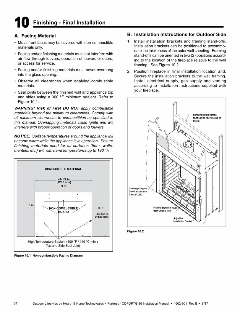
34 Outdoor Lifestyles by Hearth & Home Technologies • Fortress - ODFORTG-36 Installation Manual • 4602-901 Rev B • 8/17
10 Finishing - Final Installation
A. Facing Material• Metal front faces may be covered with non-combustible
materials only. • Facing and/or finishing materials must not interfere with
air flow through louvers, operation of louvers or doors, or access for service.
• Facing and/or finishing materials must never overhang into the glass opening.
• Observe all clearances when applying combustible materials.
• Seal joints between the finished wall and appliance top and sides using a 300 ºF minimum sealant. Refer to Figure 10.1.
WARNING! Risk of Fire! DO NOT apply combustible materials beyond the minimum clearances. Comply with all minimum clearances to combustibles as specified in this manual. Overlapping materials could ignite and will interfere with proper operation of doors and louvers.
Figure 10.1 Non-combustible Facing Diagram
NOTICE: Surface temperatures around the appliance will become warm while the appliance is in operation. Ensure finishing materials used for all surfaces (floor, walls, mantels, etc.) will withstand temperatures up to 190 °F.
0 in.0 in.
0 in.
NON-COMBUSTIBLE BOARD
COMBUSTIBLE MATERIAL
47-1/2 in.
44-1/2 in.
(1207 mm)
(1130 mm)
High Temperature Sealant (300 °F / 149 °C min.)Top and Side Seal Joint
B. Installation Instructions for Outdoor Side1. Install installation brackets and framing stand-offs.
Installation brackets can be positioned to accommo-date the thickeness of the outer wall sheeting. Framing stand-offs can be oirented in two (2) positions accord-ing to the location of the fireplace relative to the wall framing. See Figure 10.2.
2. Position fireplace in final installation location and. Secure the installation brackets to the wall framing. Install electrical supply, gas supply and venting according to installation instructions supplied with your fireplace.
Figure 10.2
Sheeting can go to Zero Clearance on Sides of Unit
Framing Stand-off, reuse from Original face
Adjustible Installation Bracket
Noncombustible MaterialMust Extend Above Stand-off Height
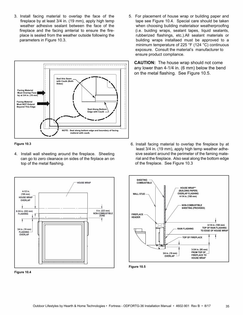
35Outdoor Lifestyles by Hearth & Home Technologies • Fortress - ODFORTG-36 Installation Manual • 4602-901 Rev B • 8/17
Seal this Seam with Caulk (Both Sides)
Seal Along Bottom Edge with Caulk
Facing Material Must Overlap Face by at 3/4 in. (19 mm)
Facing Material Must NOT Extend Beyond This Edge
NOTE: Seal along bottom edge and boundary of facing matieral with caulk.
Figure 10.4
NON-COMBUSTIBLE ZONE
FLASHINGOVERLAP
FLASHING
HOUSE WRAPOVERLAP
HOUSE WRAP
4-1/2 in.(108 mm)
8-3/4 in. (222 mm)
3/4 in. (19 mm)
8 in. (223 mm)
3. Install facing material to overlap the face of the fireplace by at least 3/4 in. (19 mm), apply high temp weather adhesive sealant between the face of the fireplace and the facing amterial to ensure the fire- place is sealed from the weather outside following the parameters in Figure 10.3.
4. Install wall sheeting around the fireplace. Sheeting can go to zero cleanace on sides of the firplace an on top of the metal flashing.
6. Install facing material to overlap the fireplace by at least 3/4 in. (19 mm), apply high temp weather adhe- sive sealant around the perimeter of the faming mate- rial and the fireplace. Also seal along the bottom edge of the fireplace. See Figure 10.3
Figure 10.5
SHEETING COMBUSTIBLE
WALL STUD
HOUSE WRAP**(BUILDING PAPER)
OVERLAP FLASHING 4-1/4 in. (108 mm)
NON-COMBUSTIBLESHEETING (PROVIDED)
FIREPLACE HEADER
RAIN FLASHING 4-1/4 in. (108 mm)
TOP OF RAIN FLASHINGTO EDGE OF HOUSE WRAP
TOP OF FIREPLACE
3-3/4 in. (95 mm)FROM TOP OF FIREPLACE TO HOUSE WRAP
3/4 in. (19 mm) OVERLAP
Figure 10.3
5. For placement of house wrap or building paper and tape see Figure 10.4. Special care should be taken when choosing building materialsor weatherproofing (i.e. buiding wraps, sealant tapes, liquid sealants, rubberized flashings, etc.).All sealant materials or building wraps installaed must be approved to a minimum temperature of 225 °F (124 °C) continuous exposure. Consult the material’s manufacturer to ensure product compliance.
CAUTION: The house wrap should not come any lower than 4-1/4 in. (6 mm) below the bend on the metal flashing. See Figure 10.5.

36 Outdoor Lifestyles by Hearth & Home Technologies • Fortress - ODFORTG-36 Installation Manual • 4602-901 Rev B • 8/17
Glass Frame Removal (Interior Side)
NOTE: You must first remove the Safety Barrier Screen before you remove the glass frame. To remove the bar-rier, lift up and pull out until the tabs are clear of their corresponding slots on the firebox. Then proceed to remove the glass frame by:
1. Remove the plate located in front of the glass at the bottom.
2. Rotate the access doors on the right and left side of the glass toward the glass.
3. Remove glass frame by releasing the three latches located at the top of the firebox. Tilt glass away from the unit, lift glass frame up and away from the unit. See Figure 10.6.
CA
UTI
ON
Each clamp has a quick spring force. When reinstalling clamps, keep fingers clear.
Figure 10.6 Remove Safety Barrier and Glass Frame
DANGERHOT GLASS WILLCAUSE BURNS.
DO NOT TOUCH GLASSUNTIL COOLED.
NEVER ALLOW CHILDRENTO TOUCH GLASS.
A barrier designed to reduce the risk of burns from the hot viewing glass is provided with this appliance and shall
be installed for the protection of children and other at risk individuals.
20306543
GLASS FRAME SAFETY BARRIER
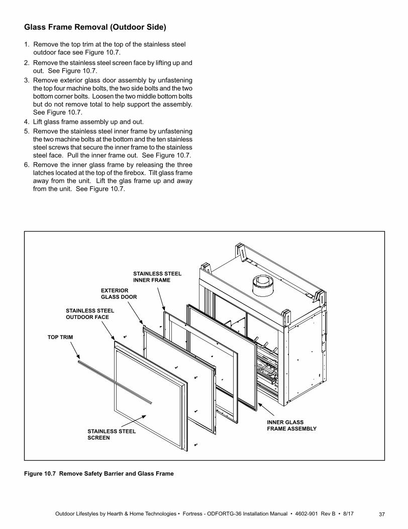
37Outdoor Lifestyles by Hearth & Home Technologies • Fortress - ODFORTG-36 Installation Manual • 4602-901 Rev B • 8/17
Glass Frame Removal (Outdoor Side)
1. Remove the top trim at the top of the stainless steel outdoor face see Figure 10.7.
2. Remove the stainless steel screen face by lifting up and out. See Figure 10.7.
3. Remove exterior glass door assembly by unfastening the top four machine bolts, the two side bolts and the two bottom corner bolts. Loosen the two middle bottom bolts but do not remove total to help support the assembly. See Figure 10.7.
4. Lift glass frame assembly up and out. 5. Remove the stainless steel inner frame by unfastening
the two machine bolts at the bottom and the ten stainless steel screws that secure the inner frame to the stainless steel face. Pull the inner frame out. See Figure 10.7.
6. Remove the inner glass frame by releasing the three latches located at the top of the firebox. Tilt glass frame away from the unit. Lift the glas frame up and away from the unit. See Figure 10.7.
Figure 10.7 Remove Safety Barrier and Glass Frame
TOP TRIM
STAINLESS STEEL SCREEN
STAINLESS STEEL OUTDOOR FACE
EXTERIOR GLASS DOOR
STAINLESS STEELINNER FRAME
INNER GLASS FRAME ASSEMBLY
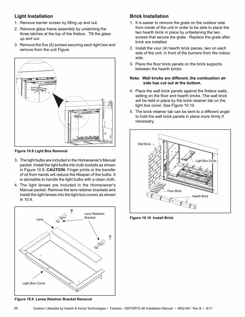
38 Outdoor Lifestyles by Hearth & Home Technologies • Fortress - ODFORTG-36 Installation Manual • 4602-901 Rev B • 8/17
FP2592install brick
Wall Brick
Floor BrickHearth Brick
Light Box Cover
Figure 10.10 Install Brick
Light Installation1. Remove barrier screen by lifting up and out.2. Remove glass frame assembly by unlatching the three latches at the top of the firebox. Tilt the glass up and out.3. Remove the five (5) screws securing each light box and
remove from the unit Figure
A
Figure 10.8 Light Box Removal
Lens
Lens Retainer Bracket
3. The light bulbs are included in the Homeowner's Manual packet. Install the light bulbs into bulb sockets as shown in Figure 10.8. CAUTION: Finger prints or the transfer of oil from hands will reduce the lifespan of the bulbs. It is advisable to handle the light bulbs with a clean cloth.
4. The light lenses are included in the Homeowner's Manual packet. Remove the lens retainer brackets and install the light lenses into the light box covers as shown in 10.9.
Figure 10.9 Lense Retainer Bracket Removal
Light Box Cover
Brick Installation1. It is easier to remove the grate on the outdoor side from inside of the unit in order to be able to place the two hearth brick in place by unfastening the two screws that secure the grate. Replace the grate after brick are installed. 2. Install the vour (4) hearth brick pieces, two on each side of the unit, in front of the burners from the indoor side. 3. Place the floor brick panels on the brick supports between the hearth bricks.
Note: Wall bricks are different, the combustion air side has cut out at the bottom.
4. Place the wall brick panels against the firebox walls, setting on the floor and hearth bricks. The wall brick will be held in place by the brick retainer tab on the light box cover. See Figure 10.10.5. The brick retainer tab can be bent to a different angle to hold the wall brick panels in place more firmly if necessary.
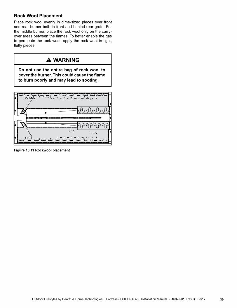
39Outdoor Lifestyles by Hearth & Home Technologies • Fortress - ODFORTG-36 Installation Manual • 4602-901 Rev B • 8/17
Rock Wool PlacementPlace rock wool evenly in dime-sized pieces over front and rear burner both in front and behind rear grate. For the middle burner, place the rock wool only on the carry-over areas between the flames. To better enable the gas to permeate the rock wool, apply the rock wool in light, fluffy pieces.
Do not use the entire bag of rock wool to cover the burner. This could cause the flame to burn poorly and may lead to sooting.
LG725rockwool
Figure 10.11 Rockwool placement
WARNING
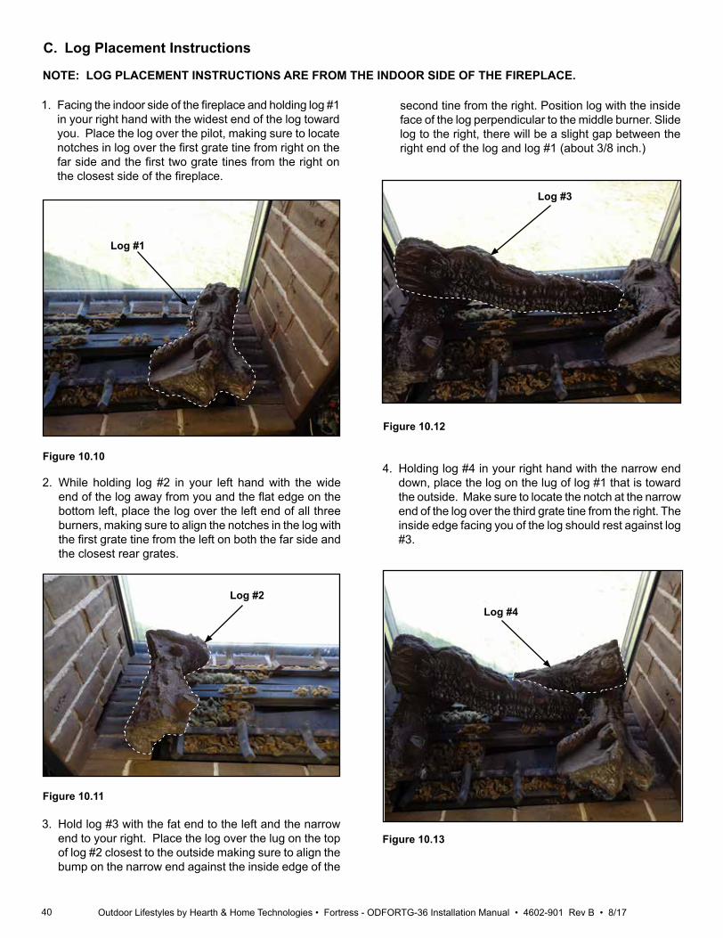
40 Outdoor Lifestyles by Hearth & Home Technologies • Fortress - ODFORTG-36 Installation Manual • 4602-901 Rev B • 8/17
C. Log Placement Instructions
1. Facing the indoor side of the fireplace and holding log #1 in your right hand with the widest end of the log toward you. Place the log over the pilot, making sure to locate notches in log over the first grate tine from right on the far side and the first two grate tines from the right on the closest side of the fireplace.
Log #1
Log #2
2. While holding log #2 in your left hand with the wide end of the log away from you and the flat edge on the bottom left, place the log over the left end of all three burners, making sure to align the notches in the log with the first grate tine from the left on both the far side and the closest rear grates.
Log #3
3. Hold log #3 with the fat end to the left and the narrow end to your right. Place the log over the lug on the top of log #2 closest to the outside making sure to align the bump on the narrow end against the inside edge of the
Figure 10.10
second tine from the right. Position log with the inside face of the log perpendicular to the middle burner. Slide log to the right, there will be a slight gap between the right end of the log and log #1 (about 3/8 inch.)
4. Holding log #4 in your right hand with the narrow end down, place the log on the lug of log #1 that is toward the outside. Make sure to locate the notch at the narrow end of the log over the third grate tine from the right. The inside edge facing you of the log should rest against log #3.
Log #4
Figure 10.11
Figure 10.12
Figure 10.13
NOTE: LOG PLACEMENT INSTRUCTIONS ARE FROM THE INDOOR SIDE OF THE FIREPLACE.
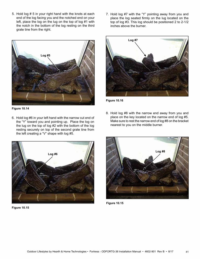
41Outdoor Lifestyles by Hearth & Home Technologies • Fortress - ODFORTG-36 Installation Manual • 4602-901 Rev B • 8/17
Log #7
6. Hold log #6 in your left hand with the narrow cut end of the “Y” toward you and pointing up. Place the log on the lug on the top of log #2 with the bottom of the log resting securely on top of the second grate tine from the left creating a “V” shape with log #5.
Figure 10.15
Figure 10.16
Log #5
5. Hold log # 5 in your right hand with the knots at each end of the log facing you and the notched end on your left, place the log on the lug on the top of log #1 with the notch in the bottom of the log resting on the third grate tine from the right.
Figure 10.14
7. Hold log #7 with the “Y” pointing away from you and place the log seated firmly on the lug located on the top of log #3. This log should be positioned 2 to 2-1/2 inches above the burner.
8. Hold log #8 with the narrow end away from you and place on the key located on the narrow end of log #5. Make sure to rest the narrow end of log #8 on the bracket nearest to you on the middle burner.
Log #6
Figure 10.15
Log #8
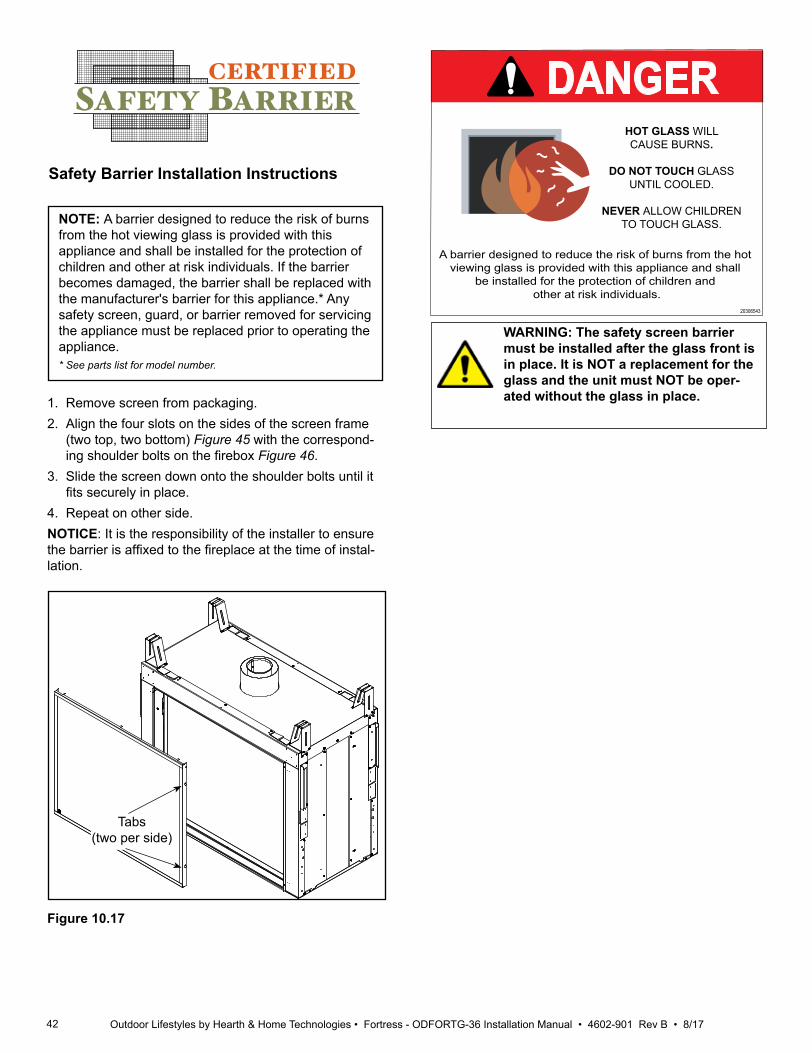
42 Outdoor Lifestyles by Hearth & Home Technologies • Fortress - ODFORTG-36 Installation Manual • 4602-901 Rev B • 8/17
Safety Barrier Installation Instructions
DANGERHOT GLASS WILLCAUSE BURNS.
DO NOT TOUCH GLASSUNTIL COOLED.
NEVER ALLOW CHILDRENTO TOUCH GLASS.
A barrier designed to reduce the risk of burns from the hot viewing glass is provided with this appliance and shall
be installed for the protection of children and other at risk individuals.
20306543
Tabs(two per side)
Figure 10.17
1. Remove screen from packaging.2. Align the four slots on the sides of the screen frame
(two top, two bottom) Figure 45 with the correspond-ing shoulder bolts on the firebox Figure 46.
3. Slide the screen down onto the shoulder bolts until it fits securely in place.
4. Repeat on other side.NOTICE: It is the responsibility of the installer to ensure the barrier is affixed to the fireplace at the time of instal-lation.
CERTIFIEDSAFETY BARRIER
NOTE: A barrier designed to reduce the risk of burns from the hot viewing glass is provided with this appliance and shall be installed for the protection of children and other at risk individuals. If the barrier becomes damaged, the barrier shall be replaced with the manufacturer's barrier for this appliance.* Any safety screen, guard, or barrier removed for servicing the appliance must be replaced prior to operating the appliance.* See parts list for model number.
WARNING: The safety screen barrier must be installed after the glass front is in place. It is NOT a replacement for the glass and the unit must NOT be oper-ated without the glass in place.
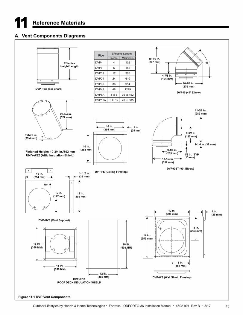
43Outdoor Lifestyles by Hearth & Home Technologies • Fortress - ODFORTG-36 Installation Manual • 4602-901 Rev B • 8/17
10-1/2 in.(267 mm)
10-7/8 in.(276 mm)
45°
7-3/8 in.(187 mm)
11-3/8 in.(289 mm)
1-1/4 in. (32 mm)
9-1/4 in.(235 mm)
13-1/4 in.(337 mm)
1/2 in. TYP
DVP90ST (90° Elbow)
10 in.(254 mm)
10 in.(254 mm)
1 in.(25 mm)
DVP-FS (Ceiling Firestop)
DVP45 (45º Elbow)DVP Pipe (see chart)
EffectiveHeight/Length
4-7/8 in.(124 mm)
(13 mm)
10 in.(254 mm)
1- 1/2 in.(38 mm)
5 in.(127 mm)
12 in.(305 mm)
UP
DVP-HVS (Vent Support)
12 in.(305 mm)
14 in.(356 mm)
1 in.(25 mm)
8 in.(203 mm)
6 in.(152 mm)
DVP-WS (Wall Shield Firestop)
Finished Height: 19-3/4 in./502 mmUNIV-AS2 (Attic Insulation Shield)
Tab=1 in.(25.4 mm)
20-3/4 in.(527 mm)
14 IN.(356 MM)
14 IN.(356 MM)
20 IN.(508 MM)
12 IN.(305 MM)
DVP-RDSROOF DECK INSULATION SHIELD
11 Reference Materials
A. Vent Components Diagrams
Figure 11.1 DVP Vent Components
Pipe Effective LengthInches Millimeters
DVP4 4 102
DVP6 6 152
DVP12 12 305
DVP24 24 610
DVP36 36 914
DVP48 48 1219
DVP6A 3 to 6 76 to 152
DVP12A 3 to 12 76 to 305
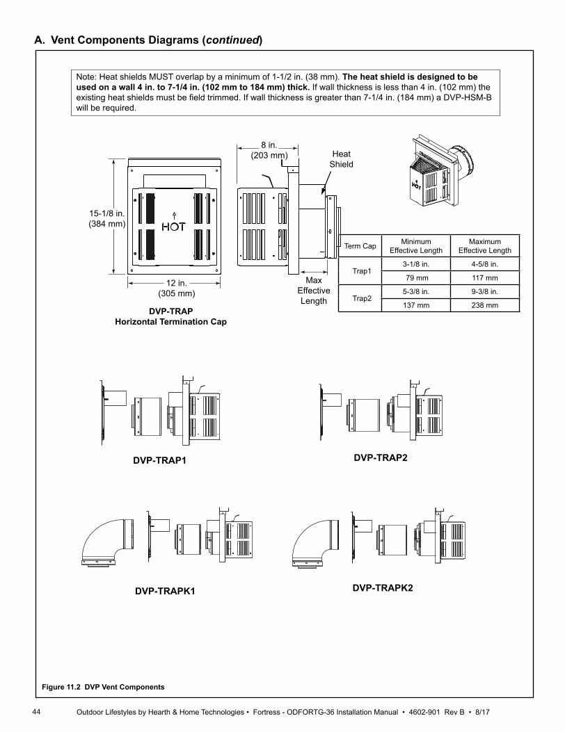
44 Outdoor Lifestyles by Hearth & Home Technologies • Fortress - ODFORTG-36 Installation Manual • 4602-901 Rev B • 8/17
DVP-TRAP1 DVP-TRAP2
DVP-TRAPK2DVP-TRAPK1
DVP-TRAPHorizontal Termination Cap
15-1/8 in.(384 mm)
12 in.(305 mm)
8 in.(203 mm)
MaxEffectiveLength
Note: Heat shields MUST overlap by a minimum of 1-1/2 in. (38 mm). The heat shield is designed to be used on a wall 4 in. to 7-1/4 in. (102 mm to 184 mm) thick. If wall thickness is less than 4 in. (102 mm) the existing heat shields must be field trimmed. If wall thickness is greater than 7-1/4 in. (184 mm) a DVP-HSM-B will be required.
HeatShield
A. Vent Components Diagrams (continued)
Figure 11.2 DVP Vent Components
Term Cap MinimumEffective Length
MaximumEffective Length
Trap13-1/8 in. 4-5/8 in.
79 mm 117 mm
Trap25-3/8 in. 9-3/8 in.
137 mm 238 mm

45Outdoor Lifestyles by Hearth & Home Technologies • Fortress - ODFORTG-36 Installation Manual • 4602-901 Rev B • 8/17
13-1/4 in.(337 mm)
24-5/8 in.(625 mm)
27-1/2 in.(699 mm)
RF6Roof Flashing
31 in.(787 mm)
24-5/8 in.(625 mm)
13-1/4 in.(337 mm)
RF12Roof Flashing
Cap ShieldDRC-RADIUS
13-7/8 in.(352 mm)
9-1/2 in.(241 mm)
14 in.(356 mm)
COOL-ADDMCap Shield
11-5/8 in.(295 mm)
5-3/4 in.(146 mm)
7-1/8 in.(181 mm)
12-1/8 in.(308 mm)
DVP-BEK2DVP-HPC Cap Brick Extension
13-7/8 in.(352 mm)
5 in.(127 mm)
11-7/8 in.(302 mm)
DVP-TRAPFL Flashing
26 in.660 mm
DVP-HSM-BExtended Heat Shield
A. Vent Components Diagrams (continued)
Figure 11.3 DVP Vent Components
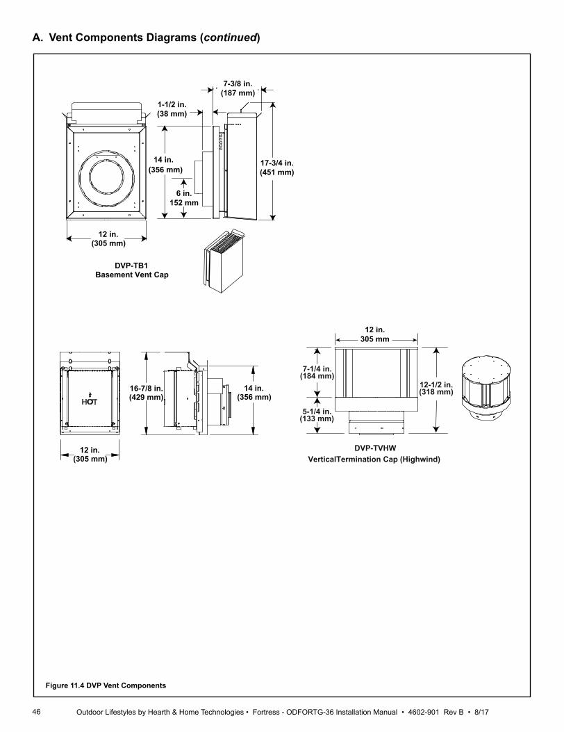
46 Outdoor Lifestyles by Hearth & Home Technologies • Fortress - ODFORTG-36 Installation Manual • 4602-901 Rev B • 8/17
DVP-TB1Basement Vent Cap
12 in.(305 mm)
1-1/2 in.(38 mm)
7-3/8 in.(187 mm)
14 in.(356 mm)
17-3/4 in.(451 mm)
7-1/4 in.
12 in.305 mm
(184 mm)
5-1/4 in.(133 mm)
12-1/2 in.(318 mm)
DVP-TVHWVerticalTermination Cap (Highwind)
14 in.(356 mm)
12 in.(305 mm)
16-7/8 in.(429 mm)
6 in.152 mm
A. Vent Components Diagrams (continued)
Figure 11.4 DVP Vent Components

47Outdoor Lifestyles by Hearth & Home Technologies • Fortress - ODFORTG-36 Installation Manual • 4602-901 Rev B • 8/17
A. Vent Components Diagrams (continued)
Figure 11.5 Vent Components
Optional Wire HarnessDESCRIPTION PART NUMBER
10 FT PV Wire Harness PVI-WH1020 FT PV Wire Harness PVI-WH2040 FT PV Wire Harness PVI-WH4060 FT PV Wire Harness PVI-WH6080 FT PV Wire Harness PVI-WH80100 FT PV Wire Harness PVI-WH100
PVI-SLPPower Vent Inline
SLP-LPCSLP Low Profile Cap
Note: Wire harnesses required to power the PVI-SLP connect to the appliance and are ordered separately from PVI-SLP. Contact your dealer to order.
16 IN.406 mm
15 IN.(381 mm)
16-11/16 IN.(424 mm)
9-3/16 IN.(233 mm)
4-1/2 IN.114 mm
16-11/16 IN.424 mm
13-5/8 IN.(346 mm)
12-1/2 IN.(318 mm)
12-1/2 IN.318 mm
20-3/4 IN.527 mm
13-5/8 IN.346 mmEFFECTIVE LENGTH
32 IN. (813 mm) MIN.35 IN. (889 mm) MAX.
Note: Use only approved termination caps with the PVI-SLP. See instructions included with PVI-SLP kit.
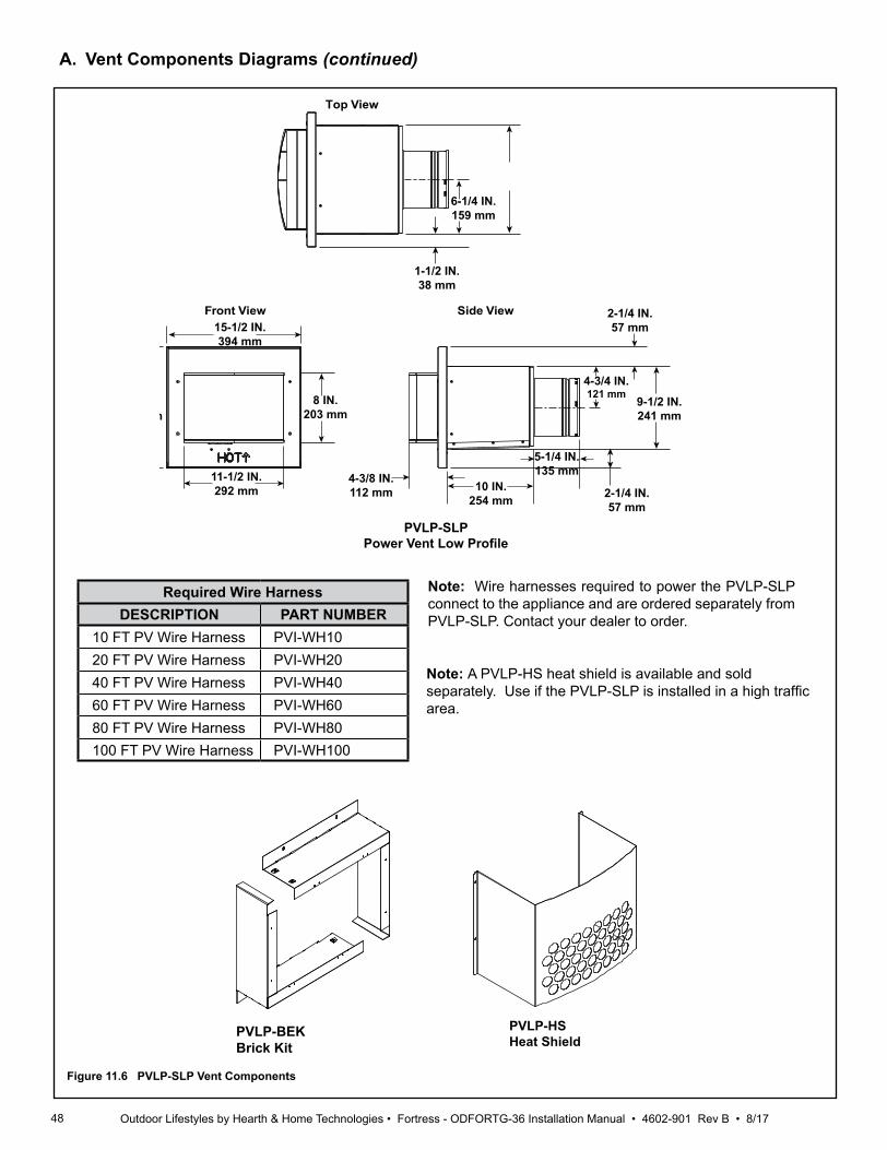
48 Outdoor Lifestyles by Hearth & Home Technologies • Fortress - ODFORTG-36 Installation Manual • 4602-901 Rev B • 8/17
A. Vent Components Diagrams (continued)
Required Wire HarnessDESCRIPTION PART NUMBER
10 FT PV Wire Harness PVI-WH1020 FT PV Wire Harness PVI-WH2040 FT PV Wire Harness PVI-WH4060 FT PV Wire Harness PVI-WH6080 FT PV Wire Harness PVI-WH80100 FT PV Wire Harness PVI-WH100
Note: Wire harnesses required to power the PVLP-SLP connect to the appliance and are ordered separately from PVLP-SLP. Contact your dealer to order.
Figure 11.6 PVLP-SLP Vent Components
PVLP-HSHeat Shield
14 IN.356 mm
15-1/2 IN.394 mm
11-1/2 IN.292 mm
8 IN.203 mm
4-3/8 IN.112 mm 10 IN.
254 mm
5-1/4 IN.135 mm
2-1/4 IN.57 mm
9-1/2 IN.241 mm
4-3/4 IN.121 mm
2-1/4 IN.57 mm
1-1/2 IN.38 mm
6-1/4 IN.159 mm
Front View
Top View
Side View
Note: A PVLP-HS heat shield is available and sold separately. Use if the PVLP-SLP is installed in a high traffic area.
PVLP-BEKBrick Kit
PVLP-SLPPower Vent Low Profile
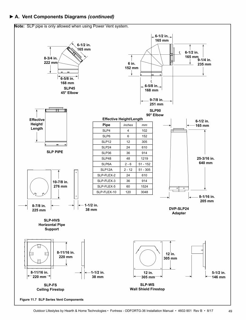
49Outdoor Lifestyles by Hearth & Home Technologies • Fortress - ODFORTG-36 Installation Manual • 4602-901 Rev B • 8/17
Figure 11.7 SLP Series Vent Components
8-3/4 in.222 mm
6-1/2 in.165 mm
6-5/8 in.168 mm
6 in.152 mm
6-1/2 in.165 mm
6-5/8 in.168 mm
9-7/8 in.251 mm
6-1/2 in.165 mm
9-1/4 in.235 mm
SLP4545° Elbow
SLP9090° Elbow
EffectiveHeight/Length
SLP PIPE
SLP-HVSHorizontal Pipe
Support
SLP-FSCeiling Firestop
SLP-WSWall Shield Firestop
DVP-SLP24Adapter
6-1/2 in.165 mm
25-3/16 in.640 mm
8-1/16 in.205 mm
10-7/8 in.276 mm
8-7/8 in.225 mm
1-1/2 in.38 mm
8-11/16 in.220 mm
8-11/16 in.220 mm
1-1/2 in.38 mm
12 in.305 mm
12 in.305 mm
5-1/2 in.146 mm
Effective Height/LengthPipe inches mm
SLP4 4 102
SLP6 6 152
SLP12 12 305
SLP24 24 610
SLP36 36 914
SLP48 48 1219
SLP6A 2 - 6 51 - 152
SLP12A 2 - 12 51 - 305
SLP-FLEX-2 24 610
SLP-FLEX-3 36 914
SLP-FLEX-5 60 1524
SLP-FLEX-10 120 3048
A. Vent Components Diagrams (continued)
Note: SLP pipe is only allowed when using Power Vent system.
►
50 Outdoor Lifestyles by Hearth & Home Technologies • Fortress - ODFORTG-36 Installation Manual • 4602-901 Rev B • 8/17
B. AccessoriesRemote Controls, Wall Controls and WallSwitchesFollow the instructions supplied with the control installed to operate your fireplace:For safety:• Install a switch lock or a wall/remote control with child
protection lockout feature.• Keep remote controls out of reach of children.See your dealer if you have questions.
Printed in U.S.A. - Copyright 2016
Outdoor Lifestyles, a brand of Hearth & Home Technologies 7571 215th Street West, Lakeville, MN 55044
www.outdoorlifestylesproducts.com
Please contact your Outdoor Lifestyles dealer with any questions or concerns. For the location of your nearest Outdoor Lifestyles dealer,
please visit www.outdoorlifestylesproducts.com