Embed Size (px)
Citation preview
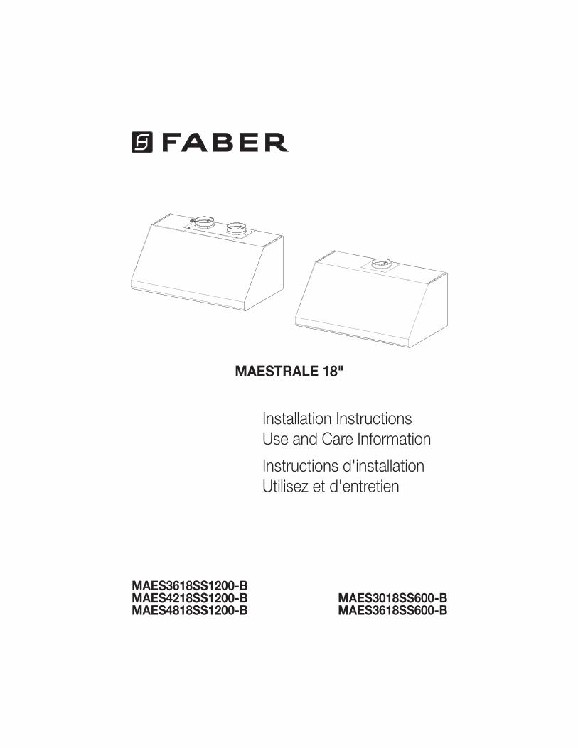
MAES3018SS600-B MAES3618SS600-B
Installation Instructions
Use and Care Information
Instructions d'installation
Utilisez et d'entretien
MAESTRALE 18"
MAES3618SS1200-B MAES4218SS1200-B MAES4818SS1200-B
2
READ AND SAVE THESE INSTRUCTIONS BEFORE YOU START INSTALLING THIS RANGEHOOD
WARNING: - TO REDUCE THE RISK OF A RANGE TOP GREASE FIRE: a) Never leave surface units unattended at high settings. Boilovers cause smoking and
greasy spillovers that may ignite. Heat oils slowly on low or medium setting.
Suzette, Cherries Jubilee, Peppercorn Beef Flambé). c) Clean ventilating fans frequently. Grease should not be allowed to accumulate on fan
d) Use proper pan size. Always use cookware appropriate for the size of the surface element.
WARNING: - TO REDUCE THE RISK OF INJURY TO PERSONS IN THE EVENT OF A RANGE TOP GREASE FIRE, OBSERVE THE FOLLOWING*:
AND CALL THE FIRE DEPARTMENT. b) NEVER PICK UP A FLAMING PAN - You may be burned. c) DO NOT USE WATER, including wet dishcloths or towels - a violent steam explosion will
result.d) Use an extinguisher ONLY if: 1. You know you have a Class ABC extinguisher, and you already know how to operate it.
* Based on "Kitchen Firesafety Tips" published by NFPA
WARNING - TO REDUCE THE RISK OF FIRE OR ELECTRIC SHOCK, do not use this fan with any solid-state speed control device.
WARNING - TO REDUCE THE RISK OF FIRE, ELECTRICAL SHOCK, OR INJURY TO PERSONS, OBSERVE THE FOLLOWING: 1. Use this unit only in the manner intended by the manufacturer. If you have any
questions, contact the manufacturer.2. Before servicing or cleaning unit, switch power off at service panel and lock the
service disconnecting means to prevent power from being switched on acciden-tally. When the service disconnecting means cannot be locked, securely fasten a prominent warning device, such as a tag, to the service panel.
CAUTION: For General Ventilating Use Only. Do Not Use To Exhaust Hazardous or Explosive Materials and Vapors.
WARNING - TO REDUCE THE RISK OF FIRE, ELECTRICAL SHOCK, OR INJURY TO PERSONS, OBSERVE THE FOLLOWING: 1. -
dance With All Applicable Codes And Standards, Including Fire-Rated Construction. 2.
heating equipment manufacturer's guideline and safety standards such as those
the local code authorities.
3
ALL WALL AND FLOOR OPENINGS WHERE THE RANGEHOOD IS INSTALLED MUST BE SEALED.
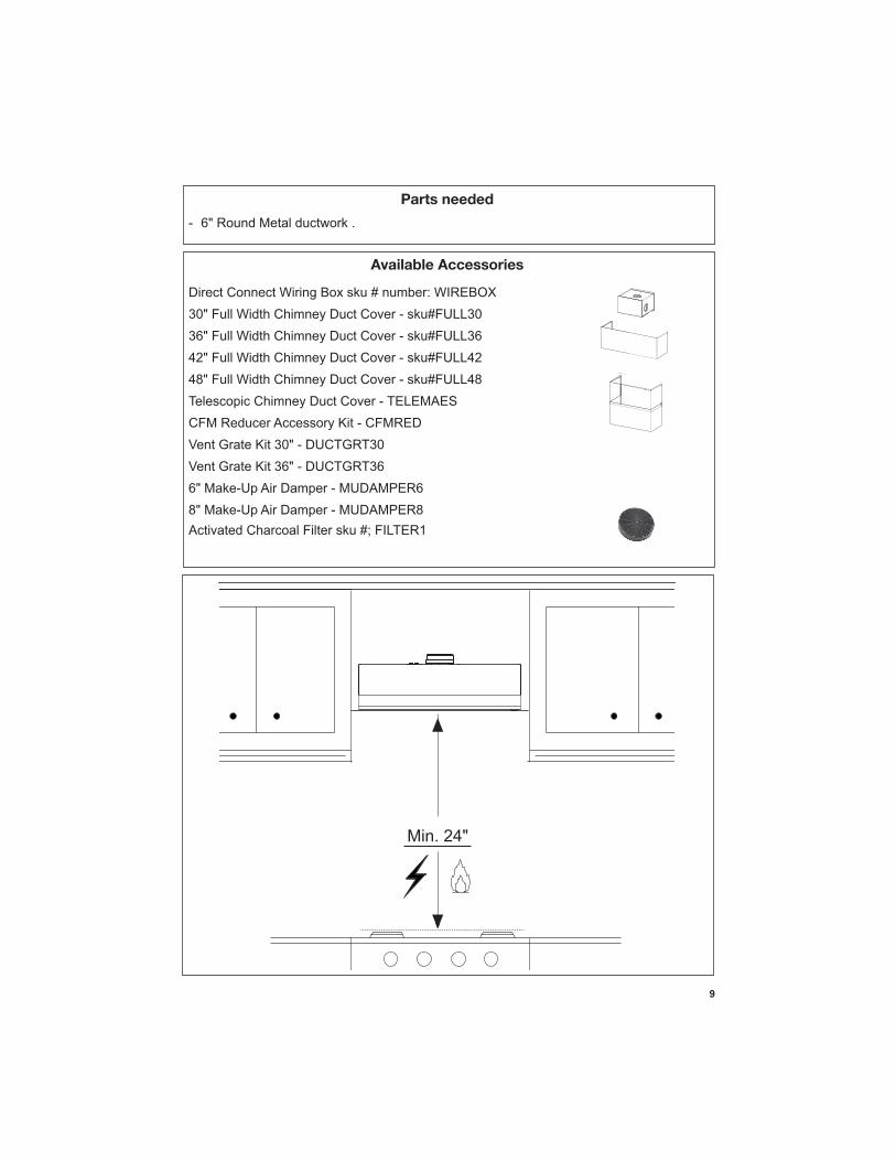
This rangehood requires at least 24" of clearance between the bottom of the rangehood and the cooking surface or countertop. This hood has been approved by UL at this distance from the cooktop. Overhead cabinets on both sides of this unit must be a minimum of 18" above the cooking surface or countertop. Consult the cooktop or range installation instructions given by the manufacturer before making any cutouts. MOBILE HOME INSTALLATION The installation of this rangehood must conform to the Manufactured Home Construction and Safety Standards, Title 24 CFR, Part 3280 (formerly Federal Standard for Mobile Home Construction and Safety, Title 24, HUD, Part 280). See Electrical Requirements.
• Venting system MUST terminate outside the home.• DO NOT terminate the ductwork in an attic or other enclosed space.• DO NOT use 4" laundry-type wall caps.• Flexible-type ductwork is not recommended.• DO NOT
WARNING!
Cold Weather installations
nonmetallic thermal break should be installed to minimize conduction of outside temperatures as part of the vent system. The damper should be on the cold air side of the thermal break. The break should be as close as possible to where the vent system enters the heated portion of the house.
VENTING REQUIREMENTSDetermine which venting method is best for your application. Ductwork can extend either through the wall or the roof.
performance. The size of the ductwork should be uniform. Do not install two elbows together. Use
around the cap.
Flexible ductwork is not recommended. Flexible ductwork creates back pressure and air turbulence that greatly reduces performance.
Do not cut a joist or stud unless absolutely necessary. If a joist or stud must be cut, then a supporting frame must be constructed.
WARNING - To Reduce The Risk Of Fire, Use Only Metal Ductwork.
not vent exhaust air into spaces within walls or ceilings or into attics, crawl spaces, or garages.
3. When cutting or drilling into wall or ceiling, do not damage electrical wiring and other hidden utilities.
4. Ducted fans must always be vented to the outdoors.
4
• Electrical ground is required on this rangehood.• If cold water pipe is interrupted by plastic, nonmetallic gaskets or other materials, DO
NOT use for grounding.• DO NOT ground to a gas pipe.• DO NOT have a fuse in the neutral or grounding circuit. A fuse in the neutral or
grounding circuit could result in electrical shock.
properly grounded.
WARNING
5
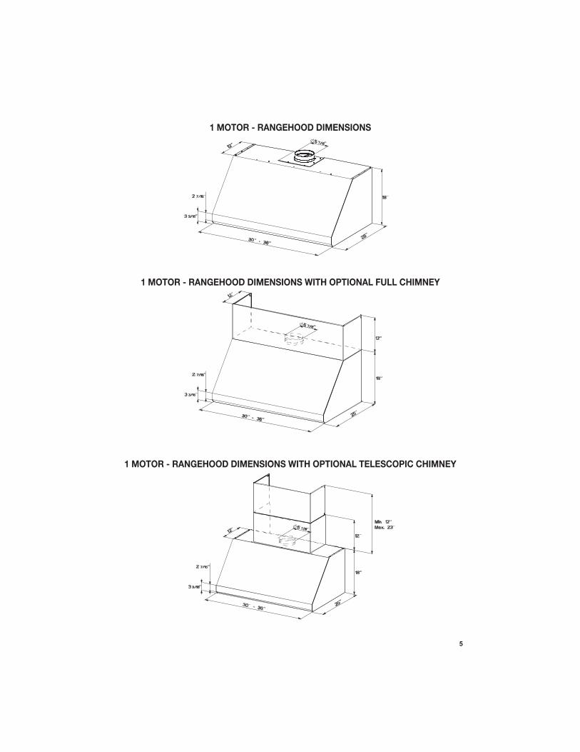
1 MOTOR - RANGEHOOD DIMENSIONS
1 MOTOR - RANGEHOOD DIMENSIONS WITH OPTIONAL FULL CHIMNEY
1 MOTOR - RANGEHOOD DIMENSIONS WITH OPTIONAL TELESCOPIC CHIMNEY
6
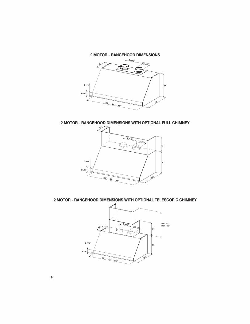
2 MOTOR - RANGEHOOD DIMENSIONS
2 MOTOR - RANGEHOOD DIMENSIONS WITH OPTIONAL FULL CHIMNEY
2 MOTOR - RANGEHOOD DIMENSIONS WITH OPTIONAL TELESCOPIC CHIMNEY
7
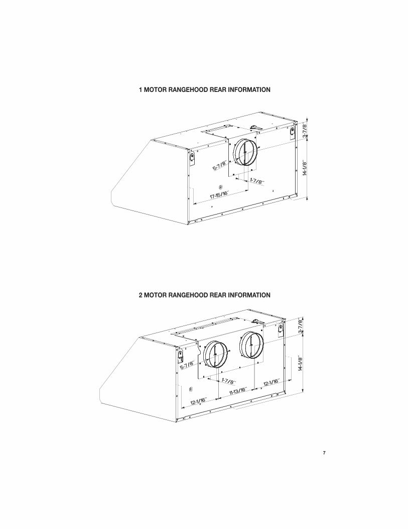
2 MOTOR RANGEHOOD REAR INFORMATION
1 MOTOR RANGEHOOD REAR INFORMATION
8
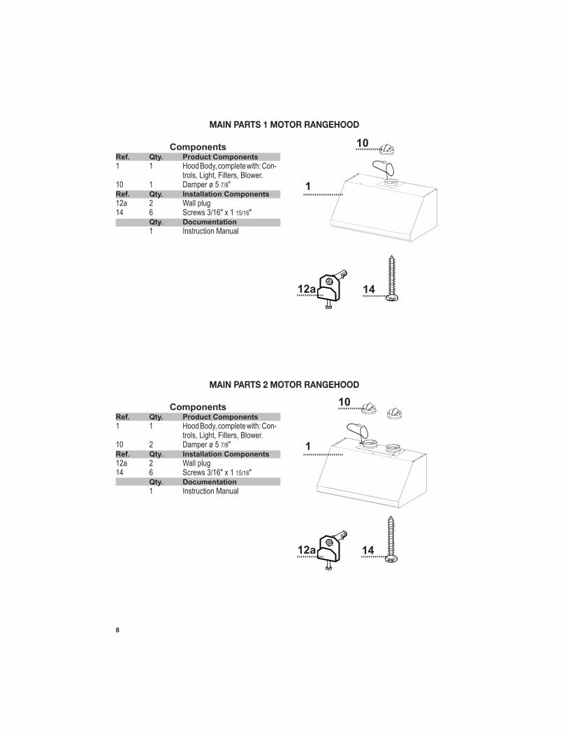
MAIN PARTS 1 MOTOR RANGEHOOD
ComponentsRef. Qty. Product Components
1 1 Hood Body, complete with: Con- trols, Light, Filters, Blower.10 1 Damper ø 5 7/8" Ref. Qty. Installation Components
12a 2 Wall plug14 6 Screws 3/16" x 1 15/16" Qty. Documentation
1 Instruction Manual
10
1
12a 14
MAIN PARTS 2 MOTOR RANGEHOOD
ComponentsRef. Qty. Product Components
1 1 Hood Body, complete with: Con- trols, Light, Filters, Blower.10 2 Damper ø 5 7/8" Ref. Qty. Installation Components
12a 2 Wall plug14 6 Screws 3/16" x 1 15/16" Qty. Documentation
1 Instruction Manual
10
1
12a 14
9
Available Accessories
Parts needed
- 6" Round Metal ductwork .
Direct Connect Wiring Box sku # number: WIREBOX
30" Full Width Chimney Duct Cover - sku#FULL30
36" Full Width Chimney Duct Cover - sku#FULL36
42" Full Width Chimney Duct Cover - sku#FULL42
48" Full Width Chimney Duct Cover - sku#FULL48
Telescopic Chimney Duct Cover - TELEMAES
CFM Reducer Accessory Kit - CFMRED
Vent Grate Kit 30" - DUCTGRT30
Vent Grate Kit 36" - DUCTGRT36
6" Make-Up Air Damper - MUDAMPER6
8" Make-Up Air Damper - MUDAMPER8
Activated Charcoal Filter sku #; FILTER1
Min. 24"
10
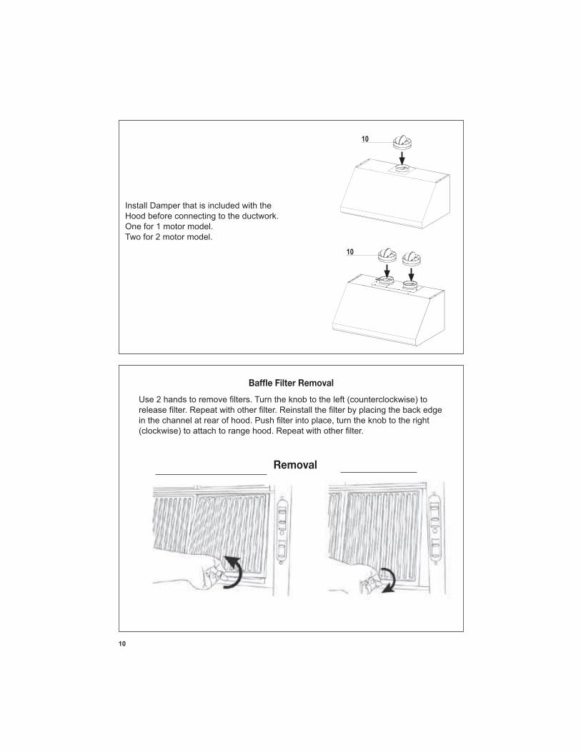
Install Damper that is included with the Hood before connecting to the ductwork.One for 1 motor model.Two for 2 motor model.
Removal / DéplacementRemoval
11
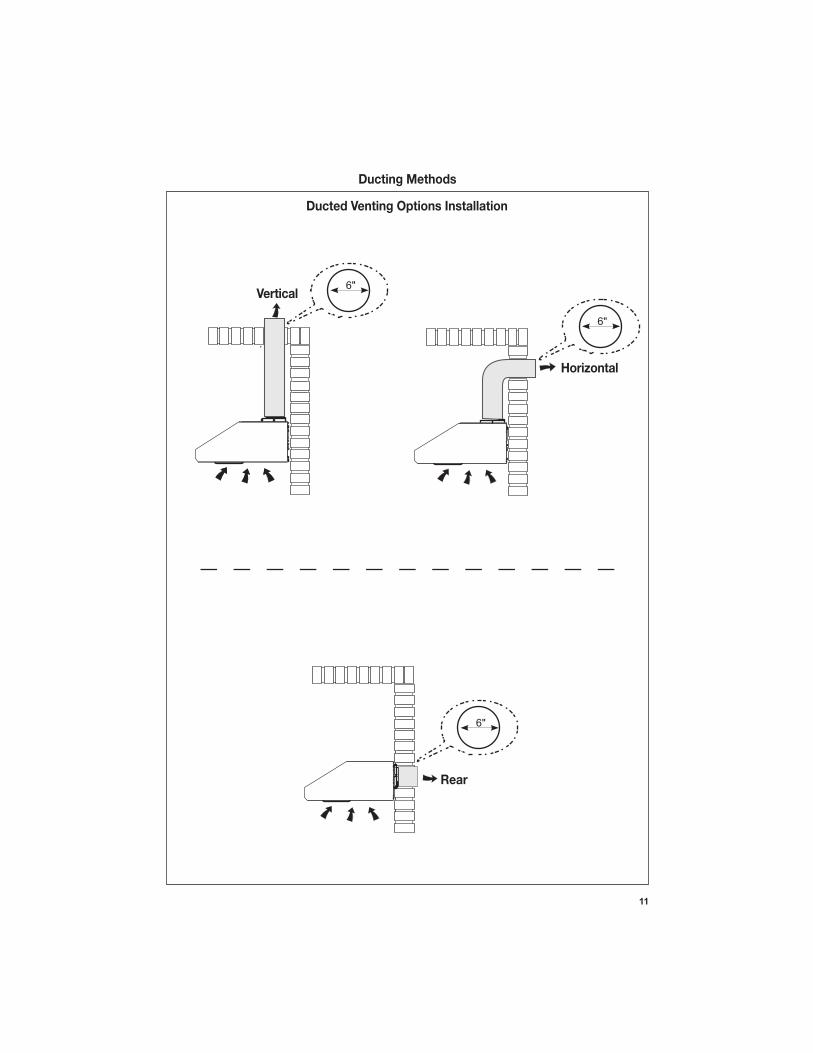
Ducted Venting Options Installation
Horizontal
Vertical6"
6"
Rear
6"
Ducting Methods
12
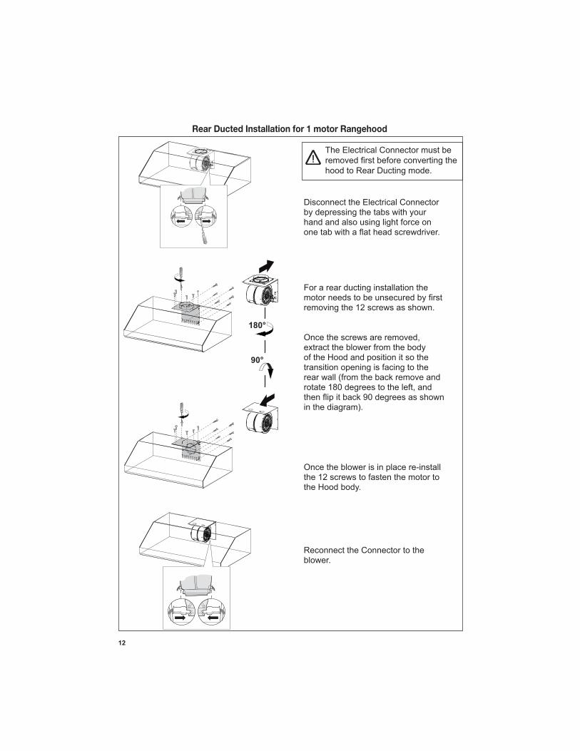
Rear Ducted Installation for 1 motor Rangehood
The Electrical Connector must be
hood to Rear Ducting mode.
For a rear ducting installation the
removing the 12 screws as shown.
extract the blower from the body of the Hood and position it so the transition opening is facing to the
Once the blower is in place re-install the 12 screws to fasten the motor to the Hood body.
Disconnect the Electrical Connector by depressing the tabs with your hand and also using light force on
Reconnect the Connector to the blower.
13
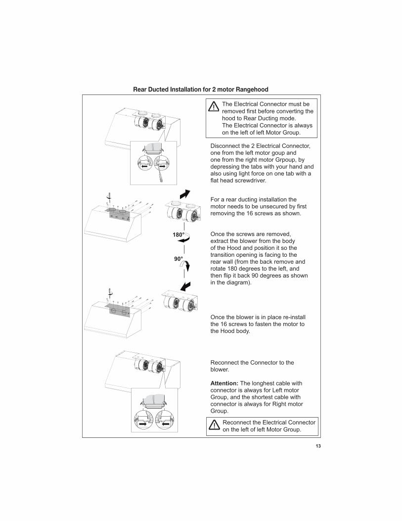
Rear Ducted Installation for 2 motor Rangehood
The Electrical Connector must be
hood to Rear Ducting mode. The Electrical Connector is always on the left of left Motor Group.
For a rear ducting installation the
removing the 16 screws as shown.
extract the blower from the body of the Hood and position it so the transition opening is facing to the
Once the blower is in place re-install the 16 screws to fasten the motor to the Hood body.
one from the left motor goup and
depressing the tabs with your hand and also using light force on one tab with a
Reconnect the Connector to the blower.
Attention: The longhest cable with connector is always for Left motor
connector is always for Right motor Group.
Reconnect the Electrical Connector on the left of left Motor Group.
14
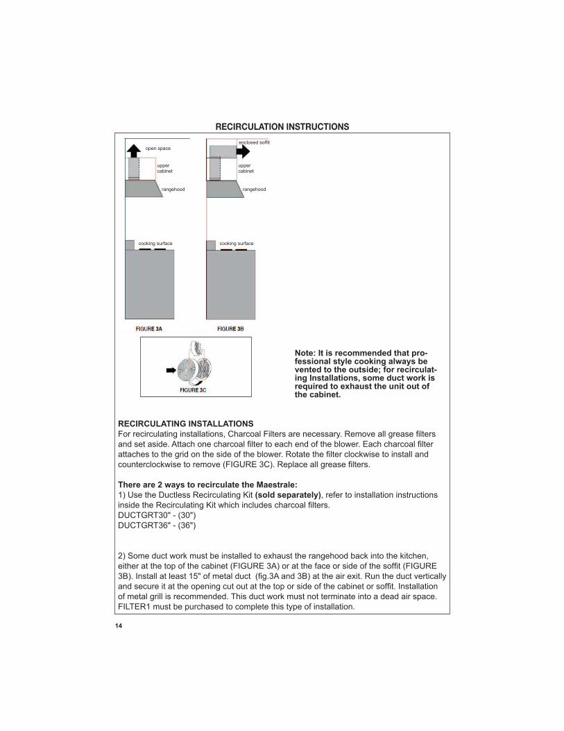
RECIRCULATION INSTRUCTIONS
Note: It is recommended that pro-fessional style cooking always be vented to the outside; for recirculat-ing Installations, some duct work is required to exhaust the unit out of the cabinet.
RECIRCULATING INSTALLATIONS
There are 2 ways to recirculate the Maestrale:
(sold separately)
of metal grill is recommended. This duct work must not terminate into a dead air space. FILTER1 must be purchased to complete this type of installation.
upper cabinet
upper cabinet
rangehood rangehood
open space
cooking surface cooking surface
15
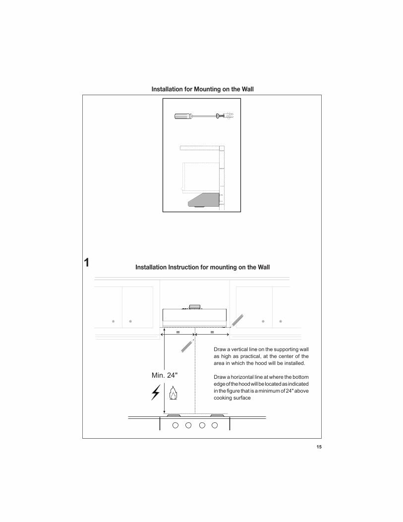
Installation for Mounting on the Wall
==
Min. 24"
Installation Instruction for mounting on the Wall
Draw a vertical line on the supporting wall
area in which the hood will be installed.
Draw a horizontal line at where the bottom edge of the hood will be located as indicated
cooking surface
1
16
22
4”
24
”
L
16
13
/16
”
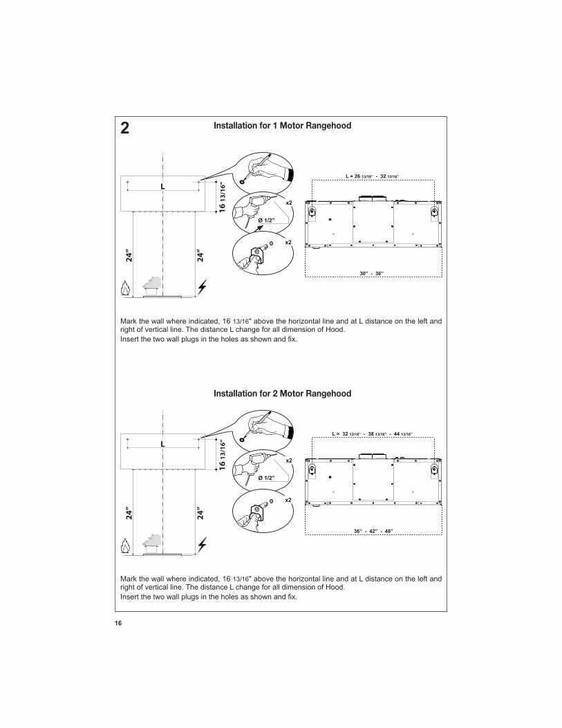
13/16" above the horizontal line and at L distance on the left and right of vertical line. The distance L change for all dimension of Hood.
Installation for 1 Motor Rangehood
Installation for 2 Motor Rangehood
24
”
24
”
L
16
13
/16
”
13/16" above the horizontal line and at L distance on the left and right of vertical line. The distance L change for all dimension of Hood.
17
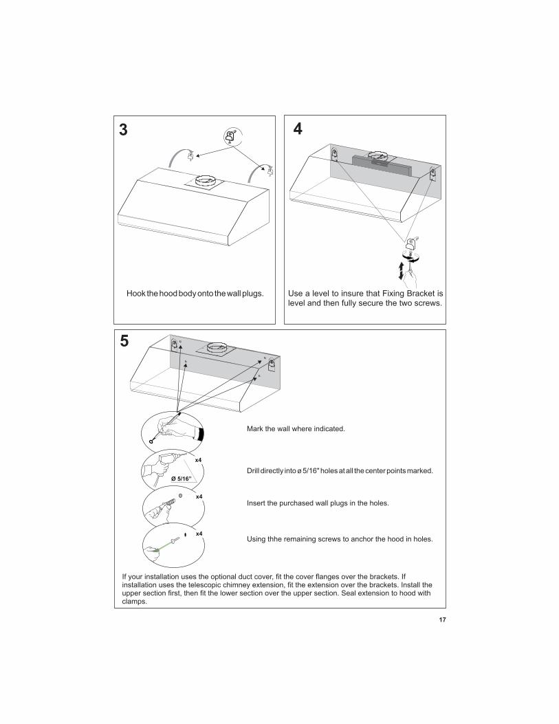
3 4
Hook the hood body onto the wall plugs. Use a level to insure that Fixing Bracket is level and then fully secure the two screws.
5
Mark the wall where indicated.
Insert the purchased wall plugs in the holes.
Using thhe remaining screws to anchor the hood in holes.
clamps.
18
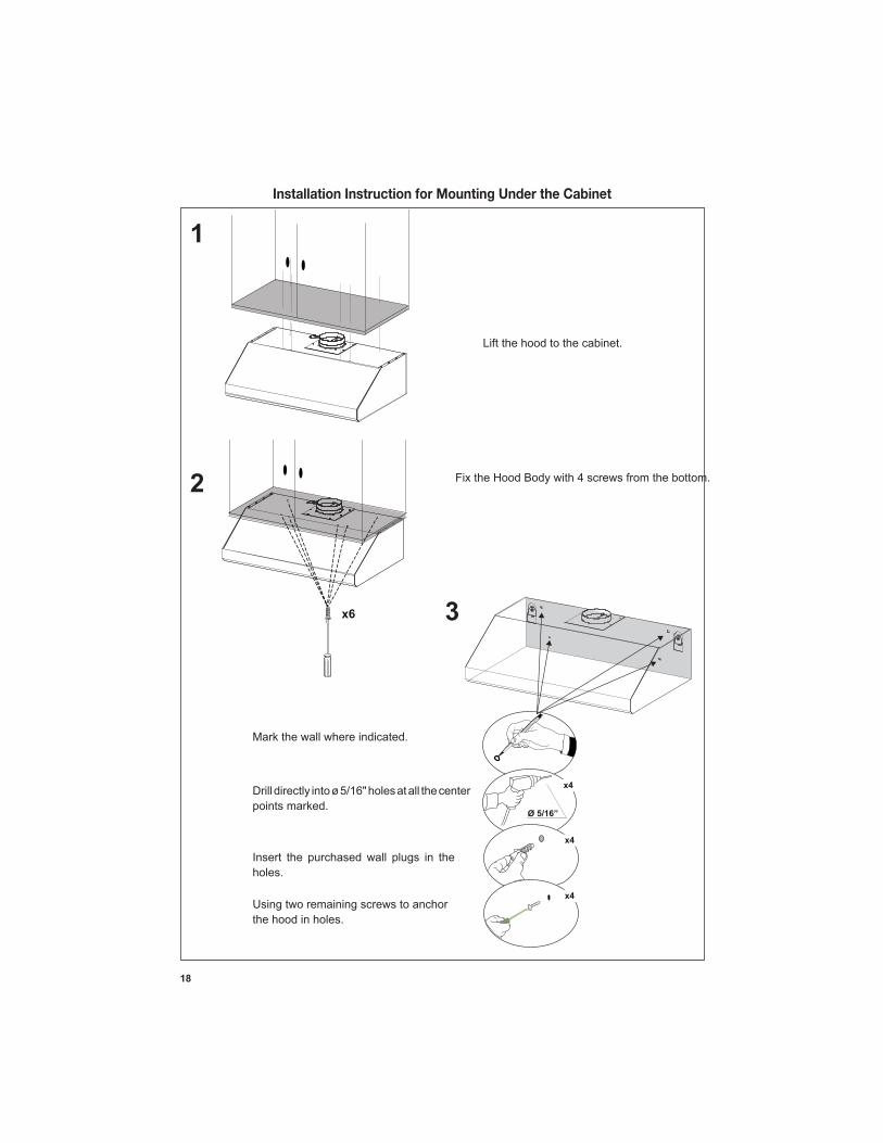
Installation Instruction for Mounting Under the Cabinet
Lift the hood to the cabinet.
Fix the Hood Body with 4 screws from the bottom.
Mark the wall where indicated.
points marked.
Insert the purchased wall plugs in the holes.
Using two remaining screws to anchor the hood in holes.
1
2
3
19
A: Distance from center of mounting bracket to centerline:
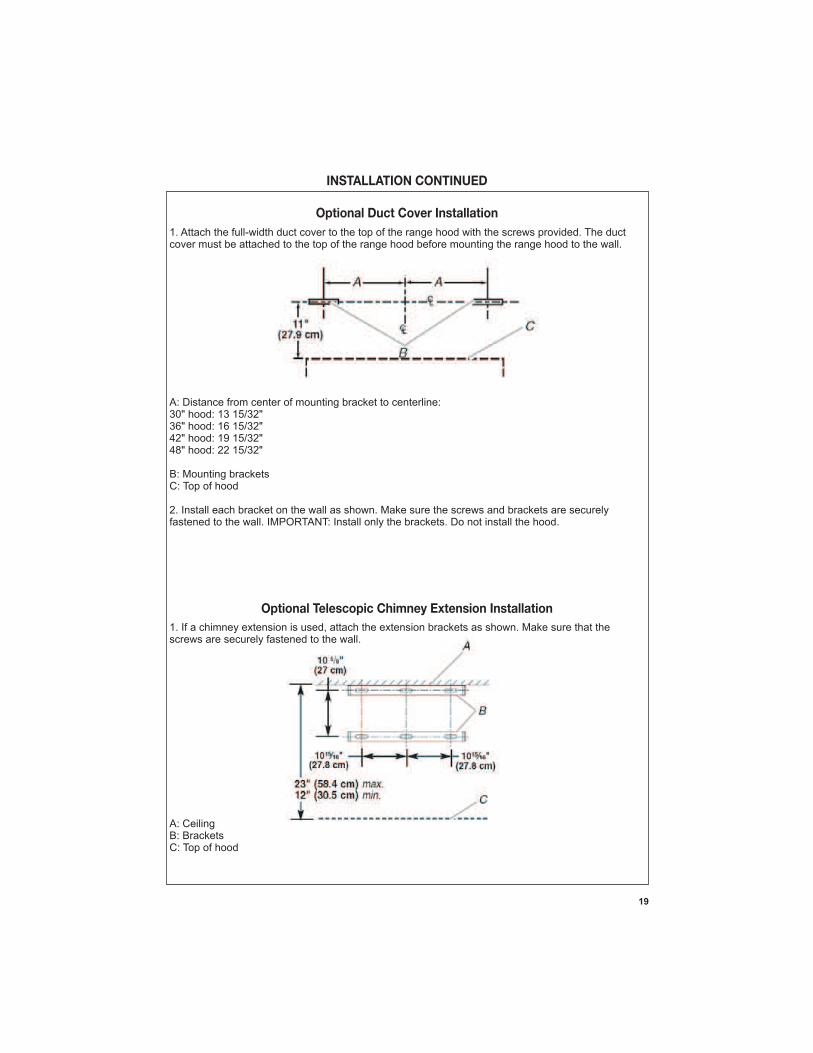
INSTALLATION CONTINUED
1. Attach the full-width duct cover to the top of the range hood with the screws provided. The duct cover must be attached to the top of the range hood before mounting the range hood to the wall.
A: Distance from center of mounting bracket to centerline:
B: Mounting brackets C: Top of hood
2. Install each bracket on the wall as shown. Make sure the screws and brackets are securely fastened to the wall. IMPORTANT: Install only the brackets. Do not install the hood.
Optional Duct Cover Installation
A: CeilingB: Brackets
Optional Telescopic Chimney Extension Installation
screws are securely fastened to the wall.
A: CeilingB: Brackets C: Top of hood
20
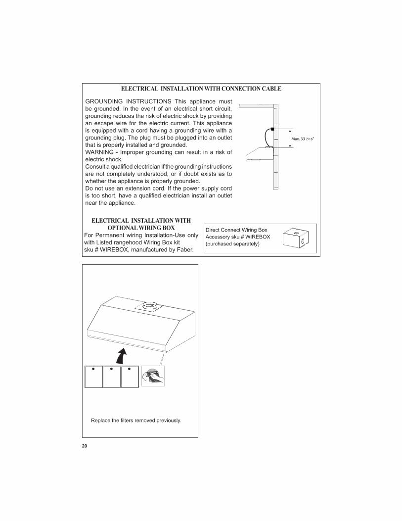
Direct Connect Wiring Box Accessory sku # WIREBOX
ELECTRICAL INSTALLATION WITH CONNECTION CABLE
ELECTRICAL INSTALLATION WITH OPTIONAL WIRING BOX
For Permanent wiring Installation-Use only with Listed rangehood Wiring Box kit
Max. 33 7/16”
GROUNDING INSTRUCTIONS This appliance must
grounding reduces the risk of electric shock by providing an escape wire for the electric current. This appliance is equipped with a cord having a grounding wire with a grounding plug. The plug must be plugged into an outlet that is properly installed and grounded.WARNING - Improper grounding can result in a risk of electric shock.
whether the appliance is properly grounded.Do not use an extension cord. If the power supply cord
near the appliance.
21
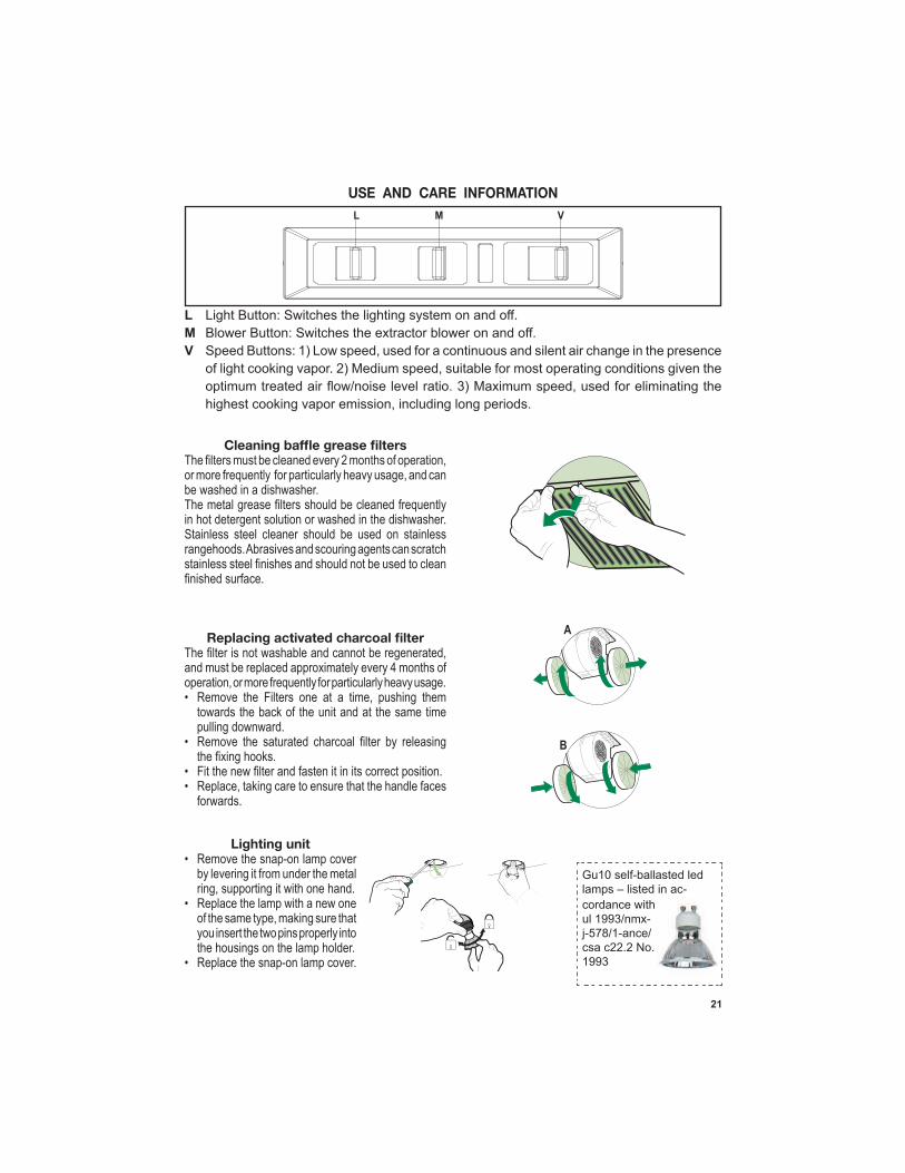
USE AND CARE INFORMATION
in hot detergent solution or washed in the dishwasher.
•
pulling downward.•
• •
A
B
L Light Button: Switches the lighting system on and off.M Blower Button: Switches the extractor blower on and off.V
Lighting unit
ring, supporting it with one hand.• Replace the lamp with a new one
you insert the two pins properly into the housings on the lamp holder.
Gu10 self-ballasted led lamps – listed in ac-cordance with
csa c22.2 No.
22
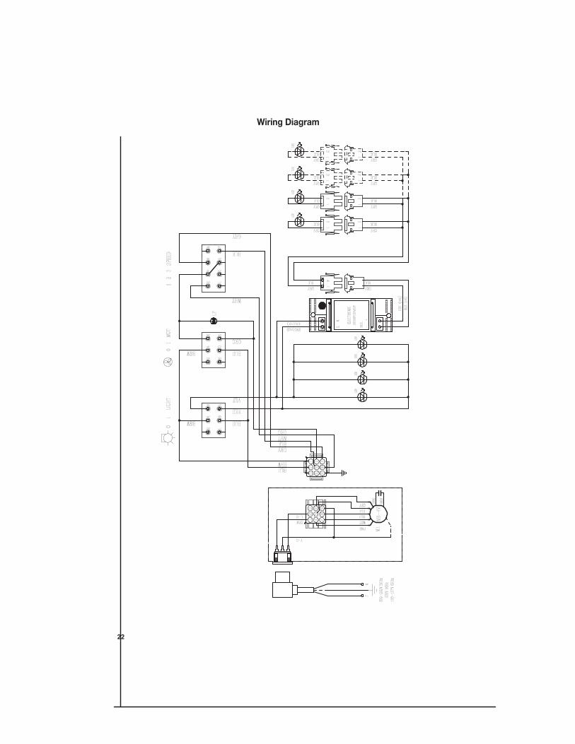
Wiring Diagram
23
January 4, 2016
FABER CONSUMER WARRANTY & SERVICE
All Faber products are warranted against any defect in materials or workmanship for the original purchaser
for a period of 1 year from the date of original purchase (requires proof of purchase). This warranty covers
labor and replacement parts. Faber, at its option, may repair or replace the product or components
necessary to restore the product to good working condition. To obtain warranty service, contact the dealer
from whom you purchased the range hood, or the local Faber distributor. If you cannot identify a local Faber
distributor, contact us at (508) 358-5353 for the name of a distributor in your area.
The following is not covered by Faber's warranty:
1. Service calls to correct the installation of your range hood, to instruct you how to use your range hood, to
replace or repair house fuses or to correct house wiring or plumbing.
2. Service calls to repair or replace range hood light bulbs, fuses or filters. Those consumable parts are
excluded from warranty coverage.
3. Repairs when your range hood is used for other than normal, single-family household use.
4. Damage resulting from accident, alteration, misuse, abuse, fire, flood, acts of God, improper installation,
installation not in accordance with electrical or plumbing codes or Faber documentation, or use of products
not approved by Faber.
5. Replacement parts or repair labor costs for units operated outside the United States or Canada, including
any non-UL or C-UL approved Faber range hoods.
6. Repairs to the hood resulting from unauthorized modifications made to the range hood.
7. Expenses for travel and transportation for product service in remote locations and pickup and delivery
charges. Faber range hoods should be serviced in the home.
THIS WARRANTY DOES NOT ALLOW RECOVERY OF INCIDENTAL OR CONSEQUENTIAL DAMAGES, INCLUDING, WITHOUT
LIMITATION, DIRECT, INDIRECT, INCIDENTAL, SPECIAL OR CONSEQUENTIAL DAMAGES, PERSONAL INJURY/WRONGFUL
DEATH OR LOST PROFITS FABER WARRANTY IS LIMITED TO THE ABOVE CONDITIONS AND TO THE WARRANTY PERIOD
SPECIFIED HEREIN AND IS EXCLUSIVE. EXCEPT AS EXPRESSLY SPECIFIED IN THIS AGREEMENT, FABER DISCLAIMS ALL
EXPRESS OR IMPLIED CONDITIONS, REPRESENTATIONS, AND WARRANTIES INCLUDING, WITHOUT LIMITATION, ANY
IMPLIED WARRANTIES OF MERCHANTABILITY OR FITNESS FOR A PARTICULAR PURPOSE.
This warranty gives you specific legal rights that may vary from state to state.
Model#: ______________________________ Serial #: _____________________________
24
VEUILLEZ LIRE ET CONSERVER LA PRÉSENTE NOTICE AVANT DE COMMENCER L'INSTALLATION DE LA HOTTE DE CUISINE
AVERTISSEMENT:-POUR RÉDUIRE LE RISQUE D'UN FEU DE GRAISSE SUR LA TABLE DE
a) Ne laissez jamais sans surveillance les éléments de la surface de cuisson à température élevée. Les bouillonnements excessifs peuvent provoquer de la fumée et les débordements de graisse
b) Assurez-vous de toujours mettre en marche le ventilateur de la hotte lorsque vous cuisinez
c) Nettoyez régulièrement les ventilateurs d'aspiration. Assurez-vous de ne pas laisser de la graisse
de cuisine de la taille adaptée à celle de l'élément chauffant.
a) ÉTOUFFEZ LES FLAMMES à l'aide d'un couvercle hermétique, d'une plaque à biscuits ou d'un plateau métallique, puis éteignez le brûleur. FAITES ATTENTION AUX BRÛLURES. Si le feu ne s'éteint pas immédiatement, QUITTEZ LES LIEUX ET APPELEZ LES POMPIERS.
b) NE PRENEZ JAMAIS UNE CASSEROLE EN FLAMME - Vous pourriez vous brûler. c) N'UTILISEZ JAMAIS DE L'EAU, ni un linge à vaisselle ou un torchon mouillé, pour éteindre le feu.
Cela pourrait provoquer une violente explosion de vapeur.
mode d'emploi. 2. Le feu est de faible intensité et se limite à l'endroit où il a démarré. 3. Les pompiers ont déjà été appelés.
AVERTISSEMENT - POUR RÉDUIRE LE RISQUE D'INCENDIE OU DE CHOC ÉLECTRIQUE, n'utilisez jamais ce ventilateur en association avec un dispositif de réglage de vitesse à semi-conducteurs.AVERTISSEMENT - POUR RÉDUIRE LES RISQUES D'INCENDIE, DE CHOC ÉLECTRIQUE OU DE
1. Utilisez cet appareil uniquement de la façon prévue par le fabricant. Pour toute question, com-muniquez avec le fabricant.
2. Avant de procéder à l'entretien ou au nettoyage de l'appareil, coupez l'alimentation au niveau du panneau électrique et verrouillez-le pour vous assurer que l'électricité n'est pas rétablie accidentel-
façon ferme et bien visible un avis de danger, par exemple à l'aide d'une étiquette sur le panneau.
pour l'aspiration de vapeurs ou de matériaux dangereux ou explosifs.AVERTISSEMENT - POUR RÉDUIRE LES RISQUES D'INCENDIE, DE CHOC ÉLECTRIQUE OU DE
1. conformément à tous les codes et normes en vigueur, incluant ceux concernant la construction à l'épreuve du feu.
2. cheminée des appareils à combustion, une bonne aération est nécessaire pour éviter le refou-lement. Respectez les lignes directrices fournies par le fabricant du matériel chauffant, ainsi que
États-Unis, ainsi que les codes en vigueur dans votre région.
25
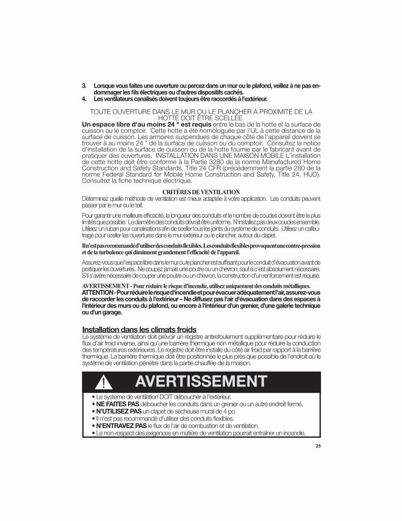
3. Lorsque vous faites une ouverture ou percez dans un mur ou le plafond, veillez à ne pas en-
4.
Un espace libre d'au moins 24 " est requis entre le bas de la hotte et la surface de
d'installation de la surface de cuisson ou de la hotte fournie par le fabricant avant de pratiquer des ouvertures. INSTALLATION DANS UNE MAISON MOBILE L'installation
norme Federal Standard for Mobile Home Construction and Safety, Title 24, HUD).
• NE FAITES PAS• N'UTILISEZ PAS
• N'ENTRAVEZ PAS• Le non-respect des exigences en matière de ventilation pourrait entraîner un incendie.
AVERTISSEMENT!
Installation dans les climats froids
CRITÈRES DE VENTILATION
passer par le mur ou le toit.
-
Il n'est pas recommandé d'utiliser des conduits flexibles. Les conduits flexibles provoquent une contre-pression et de la turbulence qui diminuent grandement l'efficacité de l'appareil.
AVERTISSEMENT - Pour réduire le risque d'incendie, utilisez uniquement des conduits métalliques.ATTENTION - Pour réduire le risque d'incendie et pour évacuer adéquatement l'air, assurez-vous
l'intérieur des murs ou du plafond, ou encore à l'intérieur d'un grenier, d'une galerie technique ou d'un garage.
26
AVERTISSEMENT
27
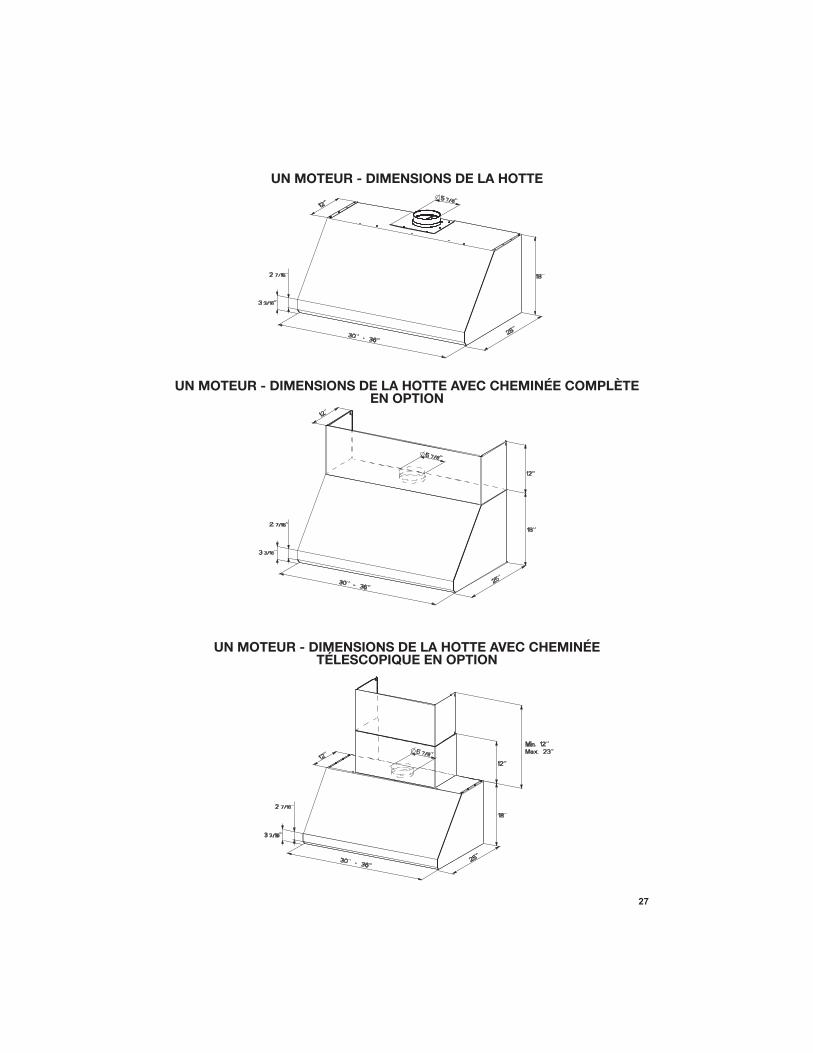
UN MOTEUR - DIMENSIONS DE LA HOTTE
UN MOTEUR - DIMENSIONS DE LA HOTTE AVEC CHEMINÉE COMPLÈTE EN OPTION
UN MOTEUR - DIMENSIONS DE LA HOTTE AVEC CHEMINÉE TÉLESCOPIQUE EN OPTION
28
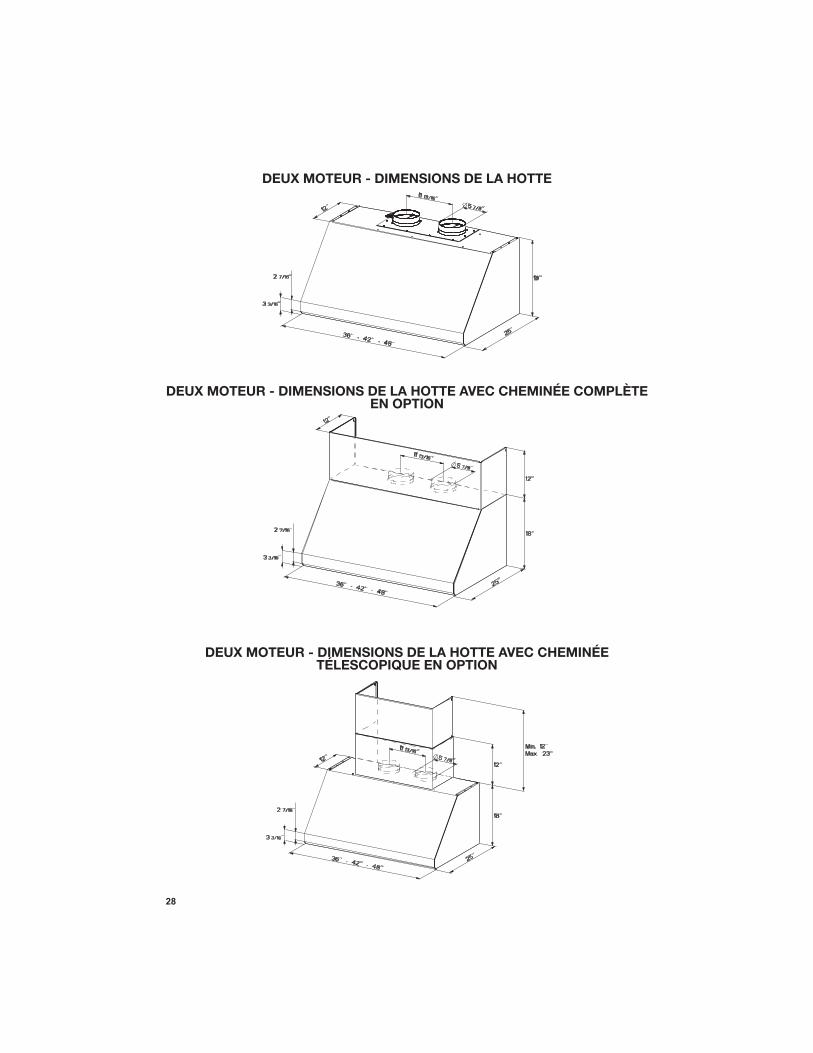
DEUX MOTEUR - DIMENSIONS DE LA HOTTE
DEUX MOTEUR - DIMENSIONS DE LA HOTTE AVEC CHEMINÉE COMPLÈTE EN OPTION
DEUX MOTEUR - DIMENSIONS DE LA HOTTE AVEC CHEMINÉE TÉLESCOPIQUE EN OPTION
29
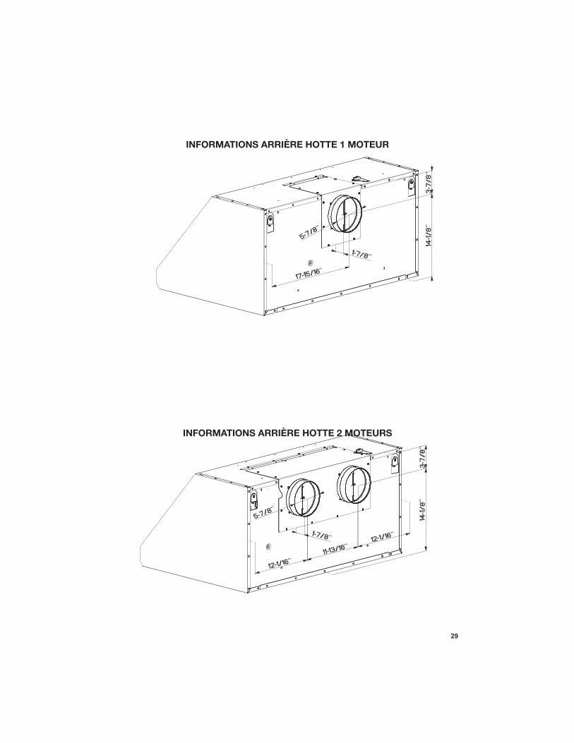
INFORMATIONS ARRIÈRE HOTTE 2 MOTEURS
INFORMATIONS ARRIÈRE HOTTE 1 MOTEUR
30
10
1
12a 14
10
1
12a 14
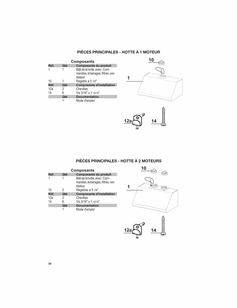
PIÈCES PRINCIPALES - HOTTE À 1 MOTEUR
ComposantsRéf. Qté Composants du produit
tilateur.10 1 Registre ø 5 7/8" Réf. Qté Composants d'installation
14 6 Vis 3/16" x 1 15/16" Qté Documentation
1 Mode d'emploi
PIÈCES PRINCIPALES - HOTTE À 2 MOTEURS
ComposantsRéf. Qté Composants du produit
tilateur.10 2 Registres ø 5 7/8" Réf. Qté Composants d'installation
14 6 Vis 3/16" x 1 15/16" Qté Documentation
1 Mode d'emploi
31
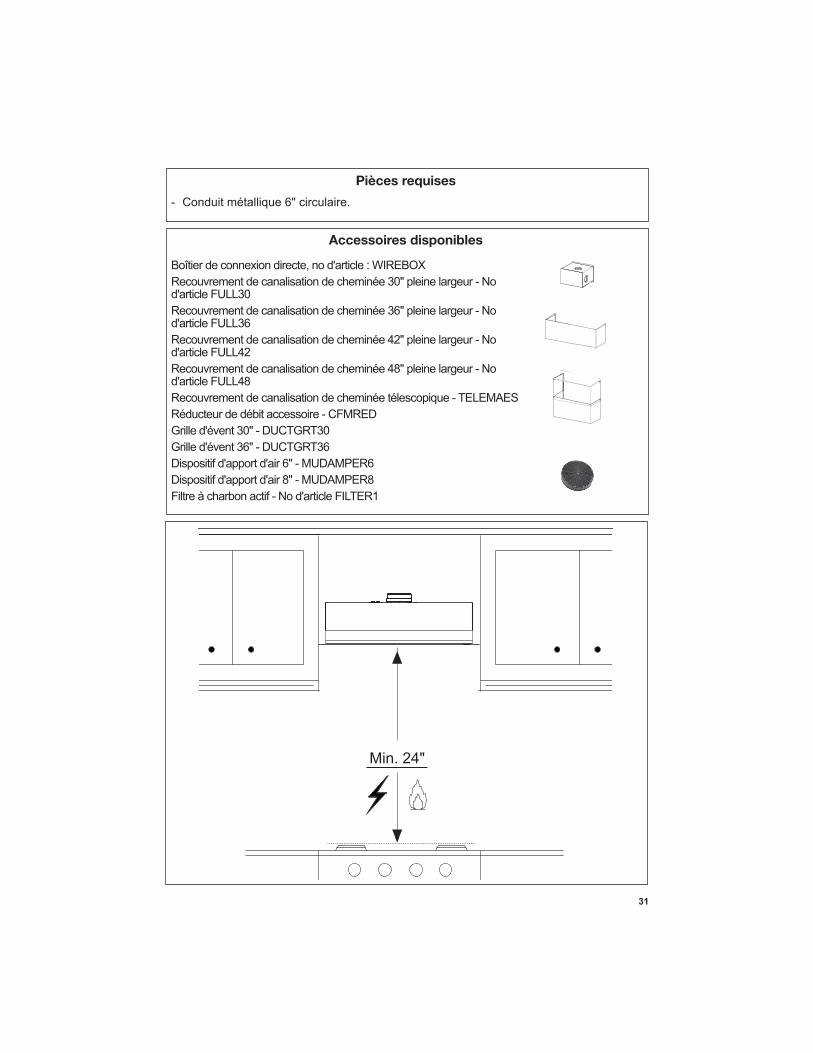
Accessoires disponibles
Pièces requises
- Conduit métallique 6" circulaire.
Recouvrement de canalisation de cheminée 30" pleine largeur - No
Recouvrement de canalisation de cheminée 36" pleine largeur - No
Recouvrement de canalisation de cheminée 42" pleine largeur - No
Recouvrement de canalisation de cheminée 48" pleine largeur - No
Recouvrement de canalisation de cheminée télescopique - TELEMAESRéducteur de débit accessoire - CFMRED
Filtre à charbon actif
Min. 24"
32
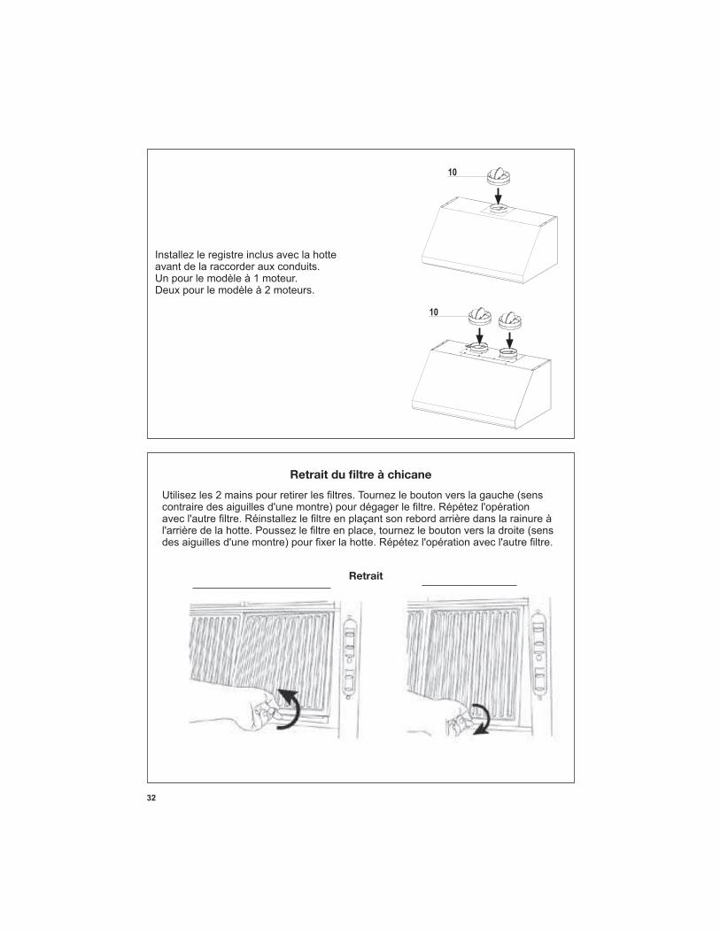
Removal / DéplacementRetrait
Installez le registre inclus avec la hotte avant de la raccorder aux conduits.
33
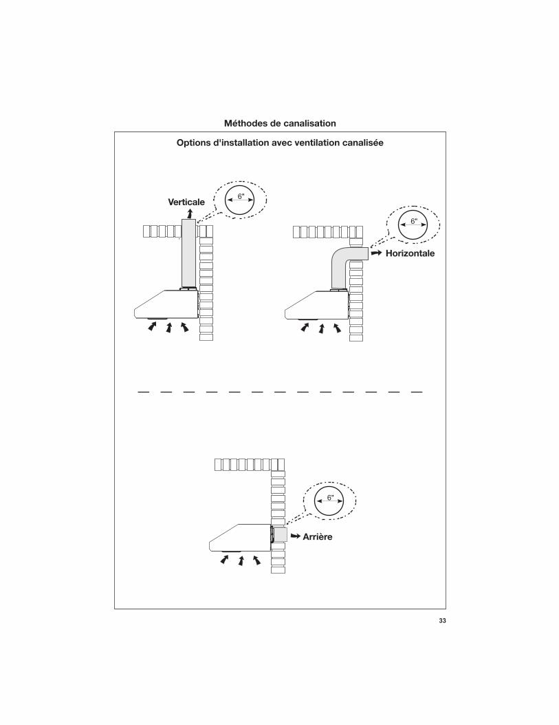
6"
6"
6"
Arrière
Horizontale
Verticale
Options d'installation avec ventilation canalisée
Méthodes de canalisation
34
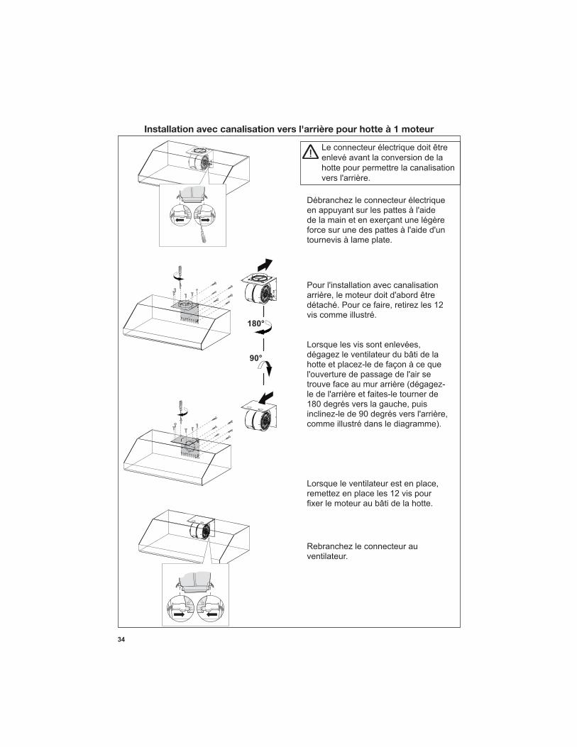
Installation avec canalisation vers l'arrière pour hotte à 1 moteur
Le connecteur électrique doit être enlevé avant la conversion de la hotte pour permettre la canalisation
vis comme illustré.
dégagez le ventilateur du bâti de la
remettez en place les 12 vis pour
Débranchez le connecteur électrique
tournevis à lame plate.
Rebranchez le connecteur au ventilateur.
35
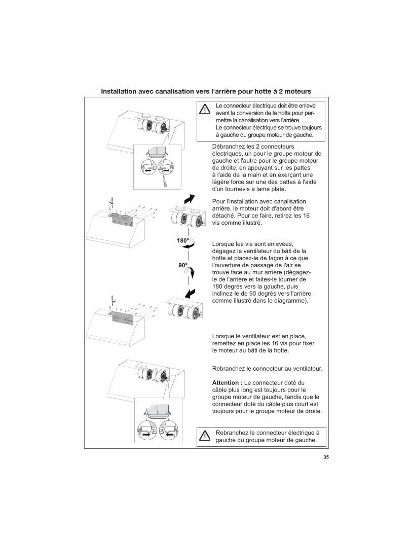
Installation avec canalisation vers l'arrière pour hotte à 2 moteurs
Le connecteur électrique doit être enlevé avant la conversion de la hotte pour per-
Le connecteur électrique se trouve toujours à gauche du groupe moteur de gauche.
vis comme illustré.
dégagez le ventilateur du bâti de la
le moteur au bâti de la hotte.
Débranchez les 2 connecteurs
Rebranchez le connecteur au ventilateur.
Attention : Le connecteur doté du câble plus long est toujours pour le
connecteur doté du câble plus court est toujours pour le groupe moteur de droite.
Rebranchez le connecteur électrique à gauche du groupe moteur de gauche.
36
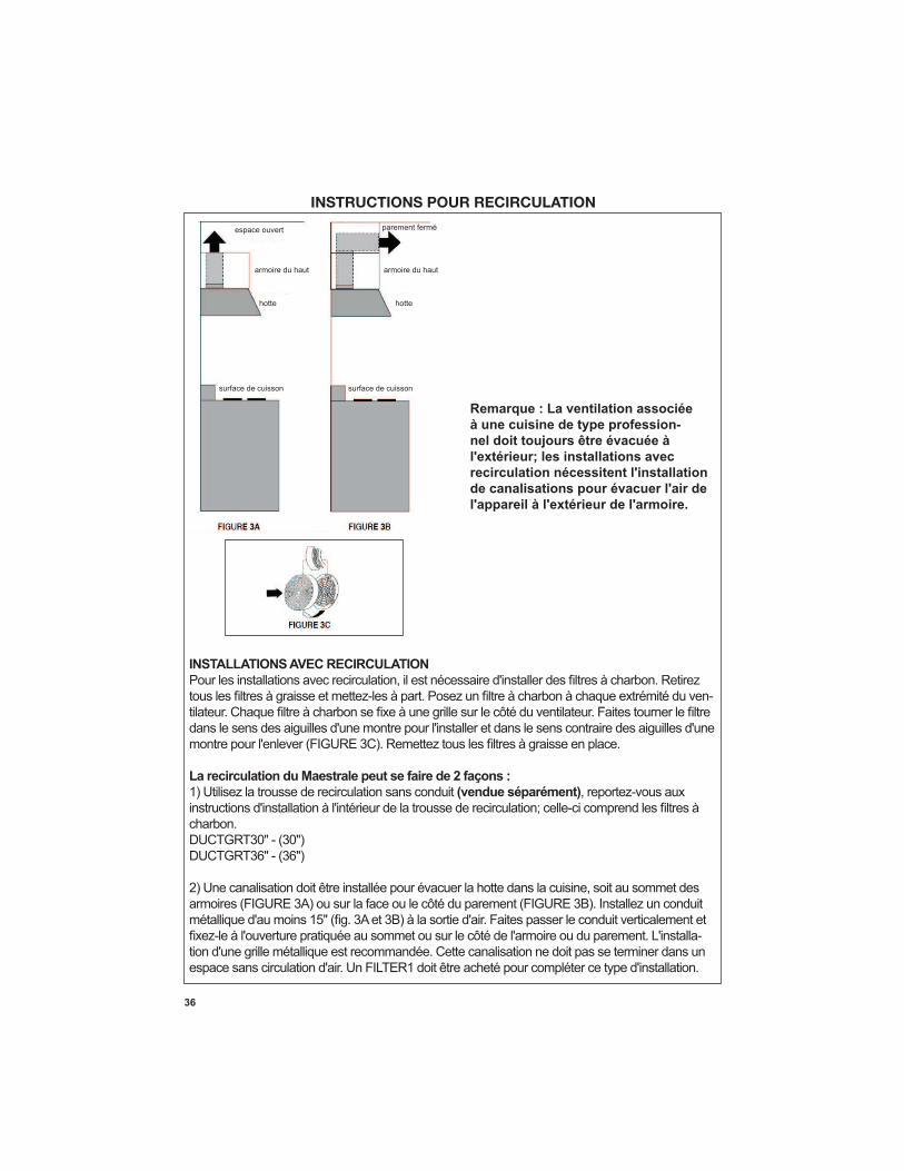
Remarque : La ventilation associée
à une cuisine de type profession-
nel doit toujours être évacuée à
l'extérieur; les installations avec
recirculation nécessitent l'installation
de canalisations pour évacuer l'air de
l'appareil à l'extérieur de l'armoire.
INSTALLATIONS AVEC RECIRCULATION
-
La recirculation du Maestrale peut se faire de 2 façons :
(vendue séparément)
charbon.
-
INSTRUCTIONS POUR RECIRCULATION
espace ouvert parement fermé
armoire du haut armoire du haut
hotte hotte
surface de cuisson surface de cuisson
37
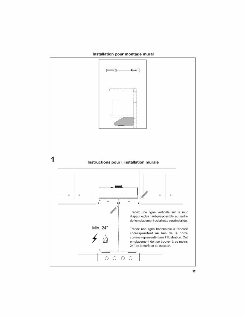
Installation pour montage mural
==
Min. 24"
Instructions pour l'installation murale
Tracez une ligne verticale sur le mur
correspondant au bas de la hotte
emplacement doit se trouver à au moins 24" de la surface de cuisson.
1
38
22
4”
24
”
L
16
13
/16
”
24
”
24
”
L
16
13
/16
”
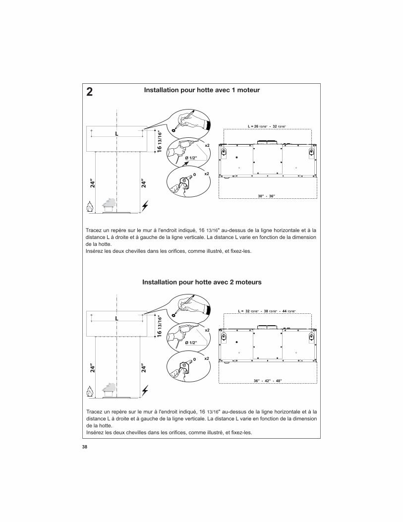
13/16" au-dessus de la ligne horizontale et à la distance L à droite et à gauche de la ligne verticale. La distance L varie en fonction de la dimension de la hotte.
Installation pour hotte avec 1 moteur
Installation pour hotte avec 2 moteurs
13/16" au-dessus de la ligne horizontale et à la distance L à droite et à gauche de la ligne verticale. La distance L varie en fonction de la dimension de la hotte.
39
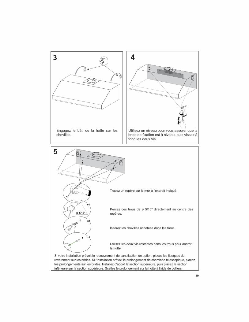
3 4
Engagez le bâti de la hotte sur les chevilles.
Utilisez un niveau pour vous assurer que la
fond les deux vis.
5
Insérez les chevilles achetées dans les trous.
Utilisez les deux vis restantes dans les trous pour ancrer la hotte.
40
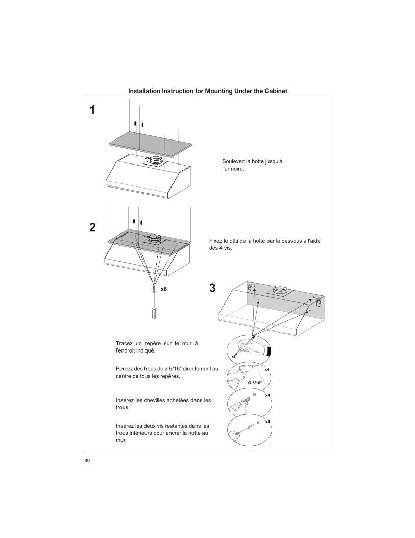
Installation Instruction for Mounting Under the Cabinet
1
2
3
Insérez les chevilles achetées dans les trous.
Insérez les deux vis restantes dans les trous inférieurs pour ancrer la hotte au mur.
des 4 vis.
41
A: Distance from center of mounting bracket to centerline:
de la hotte au mur.
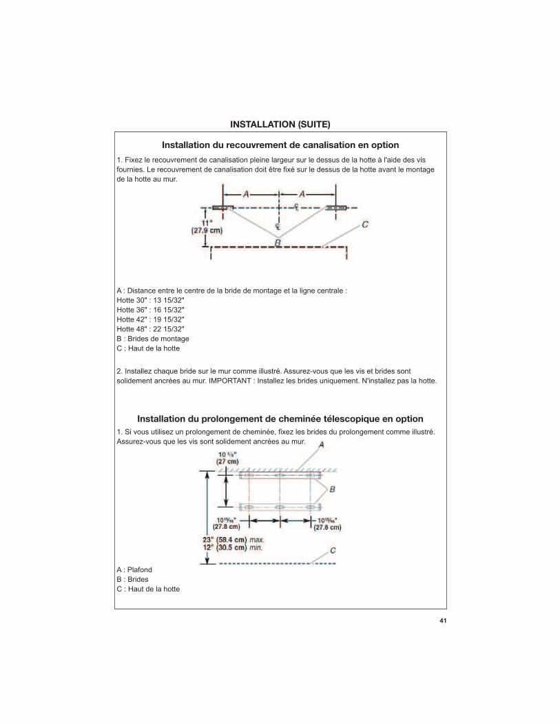
A : Distance entre le centre de la bride de montage et la ligne centrale :
B : Brides de montage C : Haut de la hotte
2. Installez chaque bride sur le mur comme illustré. Assurez-vous que les vis et brides sont
Installation du recouvrement de canalisation en option
A: CeilingB: Brackets
Installation du prolongement de cheminée télescopique en option
Assurez-vous que les vis sont solidement ancrées au mur.
A : PlafondB : Brides C : Haut de la hotte
42
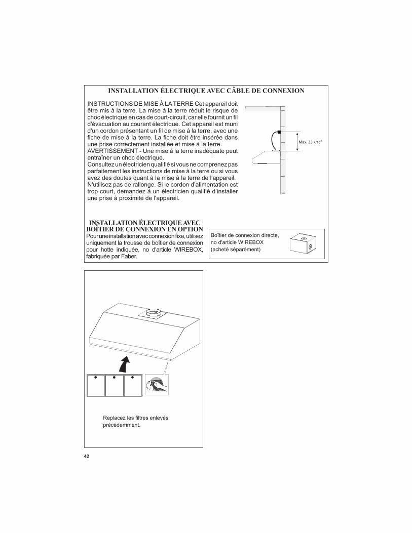
INSTALLATION ÉLECTRIQUE AVEC CÂBLE DE CONNEXION
INSTALLATION ÉLECTRIQUE AVEC BOÎTIER DE CONNEXION EN OPTION
uniquement la trousse de boîtier de connexion
fabriquée par Faber.
Max. 33 7/16”
INSTRUCTIONS DE MISE À LA TERRE Cet appareil doit être mis à la terre. La mise à la terre réduit le risque de
une prise correctement installée et mise à la terre.AVERTISSEMENT - Une mise à la terre inadéquate peut entraîner un choc électrique.
parfaitement les instructions de mise à la terre ou si vous
précédemment.
43
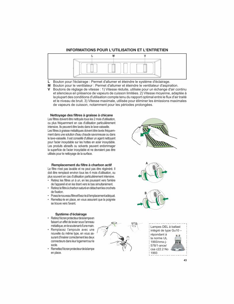
INFORMATIONS POUR L'UTILISATION ET L'ENTRETIEN
-
•
•
• •
A
B
L M V
Système d'éclairage • Retirez l'écran protecteur de la lampe en
-surant d'insérer correctement les deux connecteurs dans leur logement sur le socle.
• Remettez l'écran protecteur de la lampe en place.
Lampes DEL à ballast intégré de type Gu10 – répondant à la norme UL
csa c22.2 No

44
Schéma de câblage
45
4 janvier 2016
GARANTIE LIMITÉE ET SERVICE FABER
Tous les produits Faber font l'objet d'une garantie contre les défauts de matériel et de main-d'œuvre,accordée à l'acheteur original pour une période d'un (1) an à compter de la date d'achat initiale (preuve d'achat requise). Cette garantie couvre les frais de main-d'œuvre et les pièces de rechange. À sa discrétion, Faber peut réparer ou remplacer le produit ou les composants nécessaires à remettre le produit en bon état de marche. Pour bénéficier de services prévus par la garantie, veuillez communiquer avec le détaillant auprès duquel vous avez acheté la hotte de cuisine, ou encore avec le distributeur Faber de votre région. Si vous n'êtes pas en mesure de localiser un distributeur Faber dans votre région, veuillez communiquer avec nous au 508-358-5353 pour connaître le nom d'un distributeur à proximité.
Les éléments suivants ne sont pas visés par la garantie Faber :
1. Les appels au service de réparation visant à corriger l'installation de la hotte de cuisine, à recevoir des instructions sur l'utilisation de la hotte de cuisine, le remplacement ou la réparation des fusibles du domicile ou la correction des câblages ou de la plomberie du domicile. 2. Les appels au service de réparation visant à réparer ou remplacer les ampoules électriques de hotte, les fusibles ou les filtres. Ces pièces consommables ne sont pas couvertes par la garantie. 3. Les réparations si votre hotte de cuisine est employée à des fins autres que celles prévues, soit l'utilisation résidentielle normale pour une famille. 4. Les dommages découlant d'un accident, d'une modification, de l'utilisation incorrecte ou abusive, d'un incendie, d'une inondation, d'un cas de force majeure, d'une installation inadéquate, d'une installation non conforme aux codes en matière d'électricité ou de plomberie ou à la documentation fournie par Faber, ou encore d'une utilisation du produit non approuvée par Faber. 5. Les frais de main-d'œuvre ou de remplacement des pièces pour les appareils utilisés à l'extérieur des États-Unis ou du Canada, y compris toutes les hottes de cuisine Faber non-UL ou C-UL homologuées. 6. Les réparations à la hotte découlant de modifications non autorisées apportées à la hotte de cuisine. 7. Les frais encourus pour les déplacements et le transport de produits en région éloignée et les frais de cueillette et livraison. La réparation des hottes de cuisine Faber doit être réalisée à domicile.
LA PRÉSENTE GARANTIE NE PRÉVOIT AUCUNE FORME DE DÉDOMMAGEMENT EN CAS DE DOMMAGES ACCESSOIRES OU
CONSÉCUTIFS, Y COMPRIS, SANS TOUTEFOIS S'Y LIMITER, LES DOMMAGES DIRECTS, INDIRECTS, ACCESSOIRES,
PARTICULIERS OU CONSÉCUTIFS, LES LÉSIONS CORPORELLES/MORTELLES OU LA PERTE DE PROFITS. LA GARANTIE
OFFERTE PAR FABER EST LIMITÉE AUX CONDITIONS ÉNONCÉES CI-DESSUS ET À LA PÉRIODE DE GARANTIE INDIQUÉE
DANS LES PRÉSENTES ET EST EXCLUSIVE. SAUF DISPOSITIONS EXPRESSES CONTRAIRES DANS LE PRÉSENT ACCORD,
FABER DÉCLINE TOUTE CONDITION, REPRÉSENTATION OU GARANTIE EXPLICITE OU IMPLICITE, Y COMPRIS, SANS
TOUTEFOIS S'Y LIMITER, TOUTE GARANTIE IMPLICITE DE QUALITÉ MARCHANDE OU D'ADAPTATION À UN USAGE
PARTICULIER.
Les droits qui vous sont conférés en vertu de la présente garantie peuvent varier d'une province ou d'un État
à l'autre.
No de modèle : ______________________________ No de série : _____________________________

46

47