Embed Size (px)
Citation preview

GLASIS36SS600-B
Installation InstructionsUse and Care Information
Instructions d'installationUtilisez et d'entretien
GLASSY IS 36"

2
READ AND SAVE THESE INSTRUCTIONS BEFORE YOU START INSTALLING THIS RANGEHOOD
WARNING: - TO REDUCE THE RISK OF A RANGE TOP GREASE FIRE: a) Never leave surface units unattended at high settings. Boilovers cause smoking and
greasy spillovers that may ignite. Heat oils slowly on low or medium setting.
Suzette, Cherries Jubilee, Peppercorn Beef Flambé). c) Clean ventilating fans frequently. Grease should not be allowed to accumulate on fan
d) Use proper pan size. Always use cookware appropriate for the size of the surface element.
WARNING: - TO REDUCE THE RISK OF INJURY TO PERSONS IN THE EVENT OF A RANGE TOP GREASE FIRE, OBSERVE THE FOLLOWING*:
AND CALL THE FIRE DEPARTMENT. b) NEVER PICK UP A FLAMING PAN - You may be burned. c) DO NOT USE WATER, including wet dishcloths or towels - a violent steam explosion will
result.d) Use an extinguisher ONLY if: 1. You know you have a Class ABC extinguisher, and you already know how to operate it.
* Based on "Kitchen Firesafety Tips" published by NFPA
WARNING - TO REDUCE THE RISK OF FIRE OR ELECTRIC SHOCK, do not use this fan with any solid-state speed control device.
WARNING - TO REDUCE THE RISK OF FIRE, ELECTRICAL SHOCK, OR INJURY TO PERSONS, OBSERVE THE FOLLOWING: 1. Use this unit only in the manner intended by the manufacturer. If you have any
questions, contact the manufacturer.2. Before servicing or cleaning unit, switch power off at service panel and lock the
service disconnecting means to prevent power from being switched on acciden-tally. When the service disconnecting means cannot be locked, securely fasten a prominent warning device, such as a tag, to the service panel.
CAUTION: For General Ventilating Use Only. Do Not Use To Exhaust Hazardous or Explosive Materials and Vapors.
WARNING - TO REDUCE THE RISK OF FIRE, ELECTRICAL SHOCK, OR INJURY TO PERSONS, OBSERVE THE FOLLOWING: 1. -
dance With All Applicable Codes And Standards, Including Fire-Rated Construction. 2.
heating equipment manufacturer's guideline and safety standards such as those
the local code authorities.

3
3. When cutting or drilling into wall or ceiling, do not damage electrical wiring and other hidden utilities.
4. Ducted fans must always be vented to the outdoors.
ALL WALL AND FLOOR OPENINGS WHERE THE RANGEHOOD IS INSTALLED MUST BE SEALED.
This rangehood requires at least 24" of clearance between the bottom of the rangehood and the cooking surface or countertop. This hood has been approved by UL at this distance from the cooktop. Overhead cabinets on both sides of this unit must be a minimum of 18" above the cooking surface or countertop.Consult the cooktop or range installation instructions given by the manufacturer before making any cutouts. MOBILE HOME INSTALLATION The installation of this rangehood must conform to the Manufactured Home Construction and Safety Standards, Title 24 CFR, Part 3280 (formerly Federal Standard for Mobile Home Construction and Safety, Title 24, HUD, Part 280).
• Venting system MUST terminate outside the home.• DO NOT terminate the ductwork in an attic or other enclosed space.• DO NOT use 4" laundry-type wall caps.• Flexible-type ductwork is not recommended.• DO NOT
WARNING
Cold Weather installations
nonmetallic thermal break should be installed to minimize conduction of outside temperatures as part of the vent system. The damper should be on the cold air side of the thermal break. The break should be as close as possible to where the vent system enters the heated portion of the house.
VENTING REQUIREMENTSDetermine which venting method is best for your application. Ductwork can extend either through the wall or the roof.
performance. The size of the ductwork should be uniform. Do not install two elbows together. Use
around the cap.Flexible ductwork is not recommended. Flexible ductwork creates back pressure and air turbulence that greatly reduces performance.
Do not cut a joist or stud unless absolutely necessary. If a joist or stud must be cut, then a supporting frame must be constructed.
WARNING - To Reduce The Risk Of Fire, Use Only Metal Ductwork.
not vent exhaust air into spaces within walls or ceilings or into attics, crawl spaces, or garages.
4
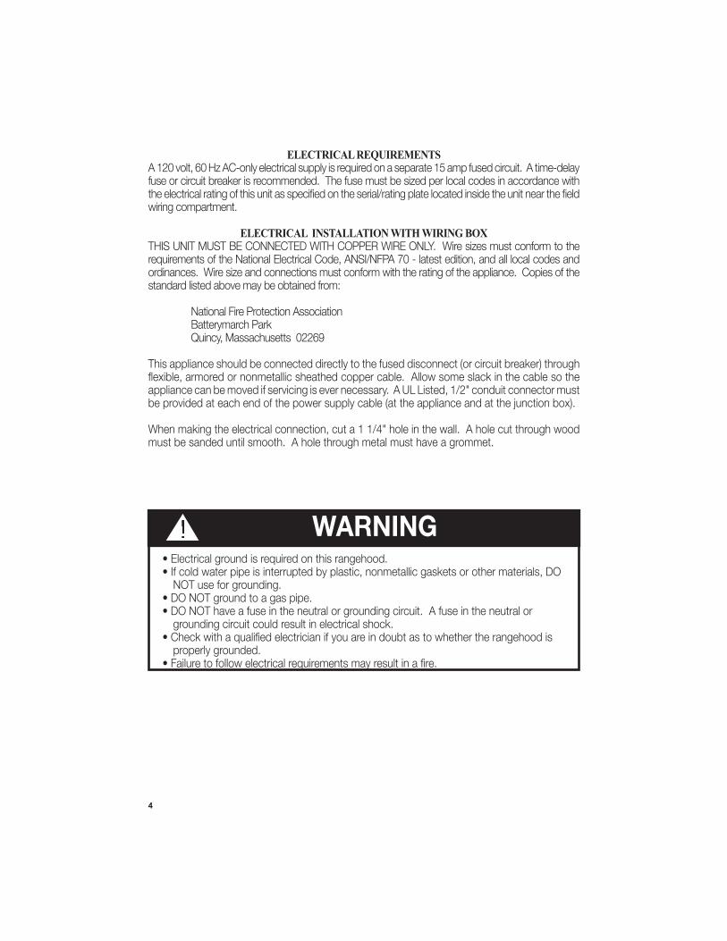
ELECTRICAL REQUIREMENTSA 120 volt, 60 Hz AC-only electrical supply is required on a separate 15 amp fused circuit. A time-delay fuse or circuit breaker is recommended. The fuse must be sized per local codes in accordance with
wiring compartment.
ELECTRICAL INSTALLATION WITH WIRING BOXTHIS UNIT MUST BE CONNECTED WITH COPPER WIRE ONLY. Wire sizes must conform to the
ordinances. Wire size and connections must conform with the rating of the appliance. Copies of the standard listed above may be obtained from:
National Fire Protection Association Batterymarch Park Quincy, Massachusetts 02269
This appliance should be connected directly to the fused disconnect (or circuit breaker) through
be provided at each end of the power supply cable (at the appliance and at the junction box).
must be sanded until smooth. A hole through metal must have a grommet.
• Electrical ground is required on this rangehood.• If cold water pipe is interrupted by plastic, nonmetallic gaskets or other materials, DO
NOT use for grounding.• DO NOT ground to a gas pipe.• DO NOT have a fuse in the neutral or grounding circuit. A fuse in the neutral or
grounding circuit could result in electrical shock.
properly grounded.
WARNING

5
RANGEHOOD DIMENSIONS
Min. 24"

6
10
MAIN PARTS
Available Accessories
- Wireless
Parts needed
ComponentsRef. Qty. Product Components
1 1 Hood Body, complete with: Con- trols, Light, Filters, Blower.2 1 Telescopic Chimney comprising: 2.1 1 Upper Section2.2 1 Lower Section 7.1 1 Telescopic frame complete with extractor, consisting of: 7.1a 1 Upper frame 7.1b 1 Lower frame 10 1 Damper ø 5 7/8"24 1 Junction BoxRef. Qty. Installation Components
12f 2 Screws 3/16" x 9/16" 12c 2 Screws 1/8" x 1/4"12e 4 Screws 1/8" x 3/8"12q 4 Screws 1/4" x 9/16"21 1 Drilling template 22 4 1/4" int. dia washers Qty. Documentation
1 Instruction Manual1
2.2
2.1
21
7.1
12q
22
12c
12e
12f
24
7.1a
7.1b
7
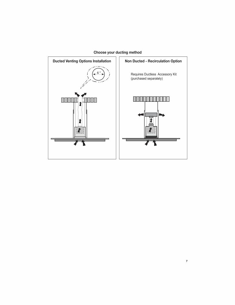
Choose your ducting method
Non Ducted - Recirculation OptionDucted Venting Options Installation
6 "

8
1
Ø 10 mm
x4
216421
6
1 1/4"
DUE TO THE SIZE AND WEIGHT OF THIS RANGE-HOOD, THE SUPPORT MUST BE FIRMLY ATTACHED TO THE CEILING. For plaster or sheet rock ceiling, the support must be attached to the joists. If this is not possible, a support structure must be built behind the plaster or sheet rock. The manufacturer assumes no re-sponsibility forinjury or damage caused by improper installa-tions.
WARNING!
9
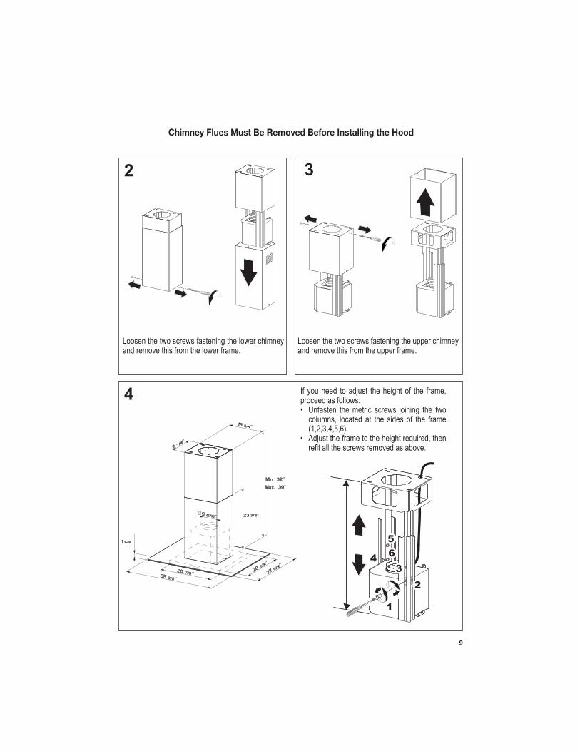
Chimney Flues Must Be Removed Before Installing the Hood
2 3
4
Loosen the two screws fastening the lower chimney and remove this from the lower frame.
If you need to adjust the height of the frame, proceed as follows:• Unfasten the metric screws joining the two
columns, located at the sides of the frame (1,2,3,4,5,6).
• Adjust the frame to the height required, then
Loosen the two screws fastening the upper chimney and remove this from the upper frame.
1
4MIN
740 mmMAX
940 mm
2
3
5
6

10
5
After the regulation for height adjustment, insert the upper chimney stack from above, and leave it running free on the frame.
Upper Flue Must Be In Place Before Proceeding
6
Install Damper that is included with the Hood before connecting to the ductwork.
Only for Ducted Venting Installation
7 Now take either your woods screws or bolts depending on your set-up and screw all four into the pilot holes and leave 1/4" of the heads exposed.Next install a UL or CSA listed strain relief in the wiring box so that the screws can be tightened after the chimney support is attached to the ceiling.
position and feed the electrical supply through the strain relief.Next position the chimney support so that the large end of the keyhole slots are over the ceiling attachment screws or bolts. Then push the chimney support so that the bolts are in the neck of the slots. Tighten all four screws or bolts securely.
• The frame mountings must be secure to withstand the weight of the hood and any stresses caused by the occasional side thrust applied to the device. On completion, check that the base is stable, even if the frame is subjected to bending.
• In all cases where the ceiling is not strong enough at the suspension point, the installer must provide strengthening using suitable plates and backing pieces anchored to the structurally sound parts.
11
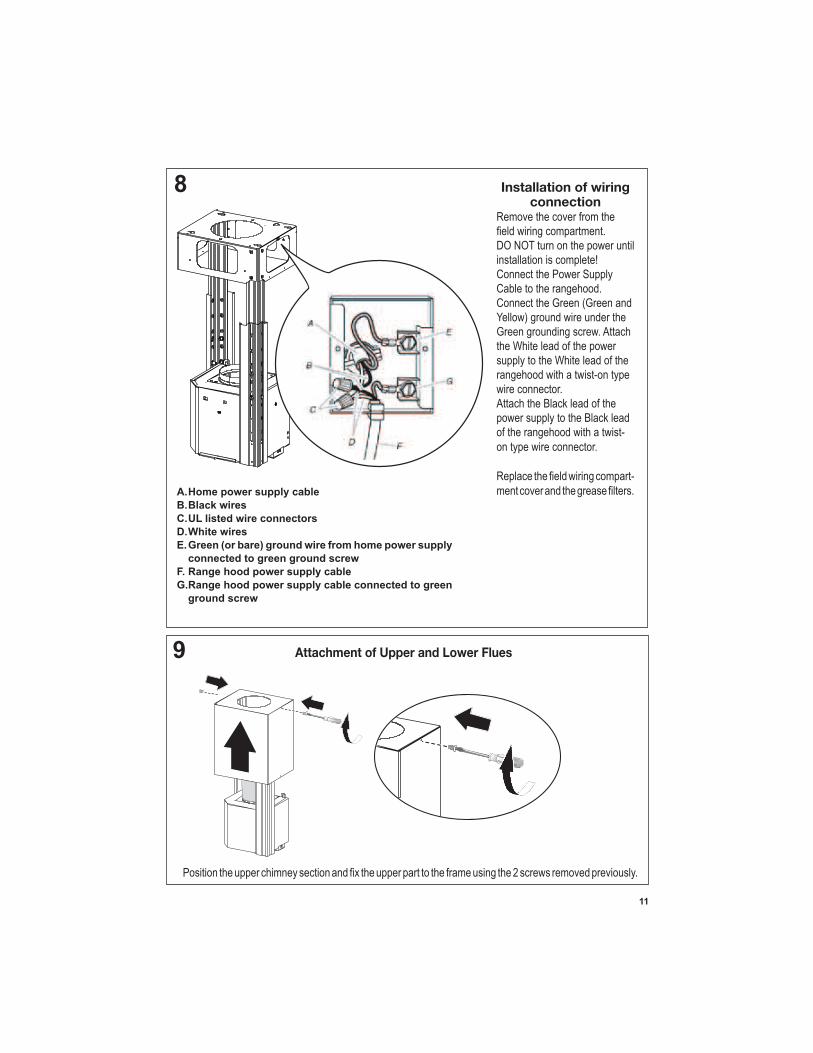
Installation of wiring connection
Remove the cover from the
DO NOT turn on the power until installation is complete! Connect the Power Supply Cable to the rangehood.Connect the Green (Green and Yellow) ground wire under the Green grounding screw. Attach the White lead of the power supply to the White lead of the rangehood with a twist-on type wire connector. Attach the Black lead of the power supply to the Black lead of the rangehood with a twist-on type wire connector.
-A. Home power supply cable
B. Black wires
C. UL listed wire connectors
D. White wires
E. Green (or bare) ground wire from home power supply
connected to green ground screw
F. Range hood power supply cable
G. Range hood power supply cable connected to green
ground screw
A. Home power supply cable
8
9 Attachment of Upper and Lower Flues

12
11
removed previously.
10
Only For Ductless Installations
Ductless installations require Ductless Conversion whose components are
. Do M
) for ductless The LOWER
(B should be
discarded and replaced by the new one with holes from
Ductless Conversion Kit
FIGURE
over the
into the FIGURE 12
Ductless installations require a Ductless Conversion Kit whose components are pictured in FIGURE 12. Do not use the DAMPER for ductless installations. The LOWER CHIMNEY COVER should be discarded and replaced by the new one with holes from the Ductless Conversion Kit (D in FIGURE 12).
As indicated in FIGURE 12, place the DUCTLESS DIVERTER (A) over the exhaust opening of the EASY CUBE (E). Fit the DUCTLESS DIVERTER EXTENSIONS HORIZONTAL (B) into the DIVERTER (A).

13
12
Screw the 2 screws 12f half way into the holes provided in the sides of the bottom of the frame.
Lift the hood canopy and engage the screws 12f in the slots as far as they will go.
12q x 4
22 x 4 hood canopy to the frame where indicated, using the 4 screws 12q and 4 washers 22 provided, then tighten all the screws securely.
12f12f
1
2
3
Attachment of Hood Canopy
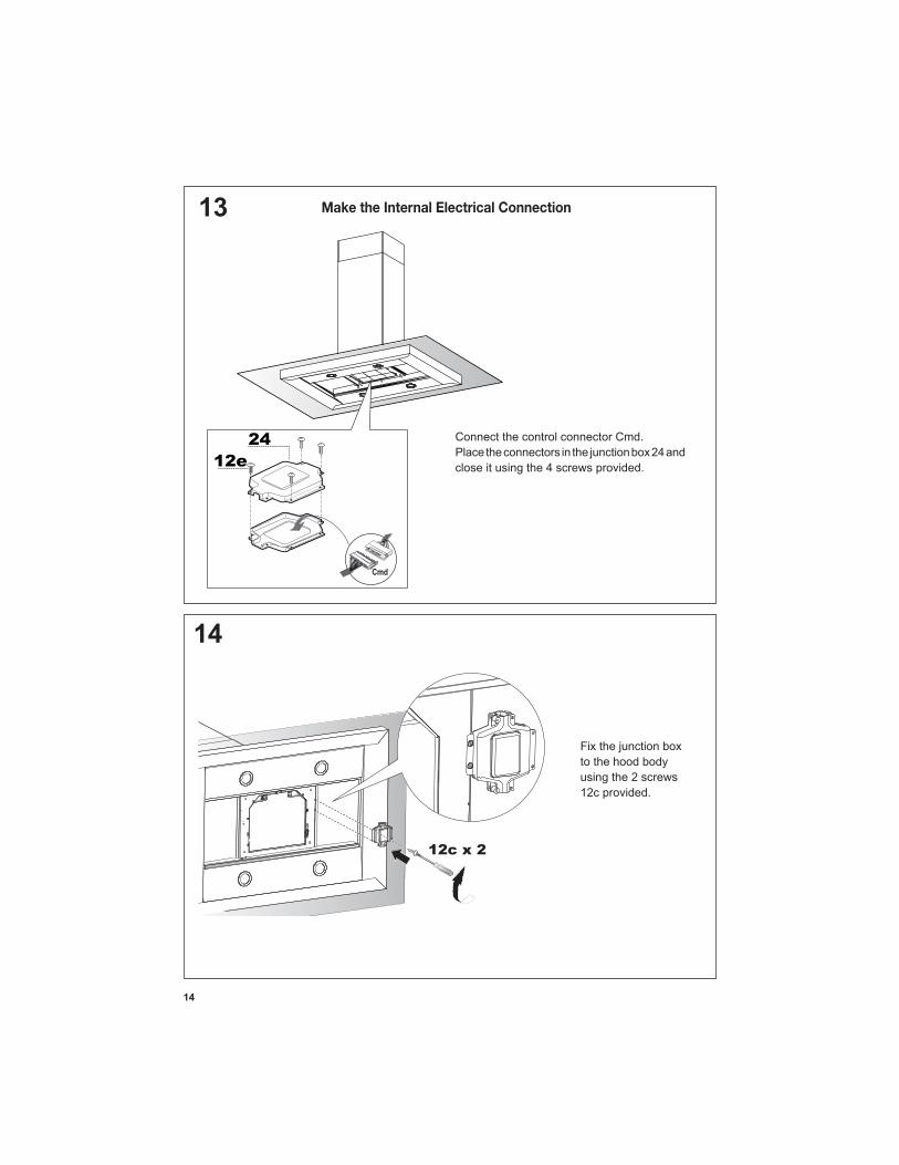
14
13
14
12c x 2
Make the Internal Electrical Connection

15
15 For Non-Ducted Recirculation Option
charcoal
correct
shown.
from the hood canopy.
16

16
USE AND CARE INFORMATION
T1
T2
T3
T4
L
LT1 T2 T3 T4
For Best Results
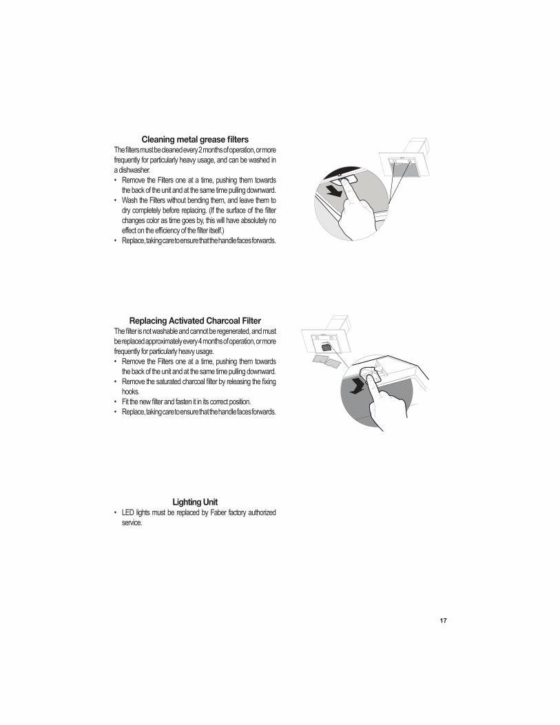
17
frequently for particularly heavy usage, and can be washed in a dishwasher.• Remove the Filters one at a time, pushing them towards
the back of the unit and at the same time pulling downward.• Wash the Filters without bending them, and leave them to
changes color as time goes by, this will have absolutely no
• Replace, taking care to ensure that the handle faces forwards.
Replacing Activated Charcoal Filter
be replaced approximately every 4 months of operation, or more frequently for particularly heavy usage.• Remove the Filters one at a time, pushing them towards
the back of the unit and at the same time pulling downward.•
hooks.• • Replace, taking care to ensure that the handle faces forwards.
Lighting Unit • LED lights must be replaced by Faber factory authorized
service.

18
Wiring Diagram
Dolce, Corrado
17-Feb-2016
19
January 4, 2016
FABER CONSUMER WARRANTY & SERVICE
All Faber products are warranted against any defect in materials or workmanship for the original purchaser
for a period of 1 year from the date of original purchase (requires proof of purchase). This warranty covers
labor and replacement parts. Faber, at its option, may repair or replace the product or components
necessary to restore the product to good working condition. To obtain warranty service, contact the dealer
from whom you purchased the range hood, or the local Faber distributor. If you cannot identify a local Faber
distributor, contact us at (508) 358-5353 for the name of a distributor in your area.
The following is not covered by Faber's warranty:
1. Service calls to correct the installation of your range hood, to instruct you how to use your range hood, to
replace or repair house fuses or to correct house wiring or plumbing.
2. Service calls to repair or replace range hood light bulbs, fuses or filters. Those consumable parts are
excluded from warranty coverage.
3. Repairs when your range hood is used for other than normal, single-family household use.
4. Damage resulting from accident, alteration, misuse, abuse, fire, flood, acts of God, improper installation,
installation not in accordance with electrical or plumbing codes or Faber documentation, or use of products
not approved by Faber.
5. Replacement parts or repair labor costs for units operated outside the United States or Canada, including
any non-UL or C-UL approved Faber range hoods.
6. Repairs to the hood resulting from unauthorized modifications made to the range hood.
7. Expenses for travel and transportation for product service in remote locations and pickup and delivery
charges. Faber range hoods should be serviced in the home.
THIS WARRANTY DOES NOT ALLOW RECOVERY OF INCIDENTAL OR CONSEQUENTIAL DAMAGES, INCLUDING, WITHOUT
LIMITATION, DIRECT, INDIRECT, INCIDENTAL, SPECIAL OR CONSEQUENTIAL DAMAGES, PERSONAL INJURY/WRONGFUL
DEATH OR LOST PROFITS FABER WARRANTY IS LIMITED TO THE ABOVE CONDITIONS AND TO THE WARRANTY PERIOD
SPECIFIED HEREIN AND IS EXCLUSIVE. EXCEPT AS EXPRESSLY SPECIFIED IN THIS AGREEMENT, FABER DISCLAIMS ALL
EXPRESS OR IMPLIED CONDITIONS, REPRESENTATIONS, AND WARRANTIES INCLUDING, WITHOUT LIMITATION, ANY
IMPLIED WARRANTIES OF MERCHANTABILITY OR FITNESS FOR A PARTICULAR PURPOSE.
This warranty gives you specific legal rights that may vary from state to state.
Model#: ______________________________ Serial #: _____________________________

20
VEUILLEZ LIRE ET CONSERVER LA PRÉSENTE NOTICE AVANT DE COMMENCER L'INSTALLATION DE LA HOTTE DE CUISINE
AVERTISSEMENT : POUR RÉDUIRE LE RISQUE D'UN FEU DE GRAISSE SUR LA TABLE DE
a) Ne laissez jamais sans surveillance les éléments de la surface de cuisson à température élevée. Les bouillonnements excessifs peuvent provoquer de la fumée et les débordements de graisse
b) Assurez-vous de toujours mettre en marche le ventilateur de la hotte lorsque vous cuisinez à
c) Nettoyez régulièrement les ventilateurs d'aspiration. Assurez-vous de ne pas laisser de la
de cuisine de la taille adaptée à celle de l'élément chauffant.
a) ÉTOUFFEZ LES FLAMMES à l'aide d'un couvercle hermétique, d'une plaque à biscuits ou d'un plateau métallique, puis éteignez le brûleur. FAITES ATTENTION AUX BRÛLURES. Si le feu ne s'éteint pas immédiatement, QUITTEZ LES LIEUX ET APPELEZ LES POMPIERS.
b) NE PRENEZ JAMAIS UNE CASSEROLE EN FLAMME - Vous pourriez vous brûler. c) N'UTILISEZ JAMAIS DE L'EAU, ni un linge à vaisselle ou un torchon mouillé, pour éteindre le
feu. Cela pourrait provoquer une violente explosion de vapeur.
son mode d'emploi. 2. Le feu est de faible intensité et se limite à l'endroit où il a démarré. 3. Les pompiers ont déjà été appelés.
AVERTISSEMENT - POUR RÉDUIRE LE RISQUE D'INCENDIE OU DE CHOC ÉLECTRIQUE, n'utilisez jamais ce ventilateur en association avec un dispositif de réglage de vitesse à semi-conducteurs.AVERTISSEMENT - POUR RÉDUIRE LES RISQUES D'INCENDIE, DE CHOC ÉLECTRIQUE OU
1. Utilisez cet appareil uniquement de la façon prévue par le fabricant. Pour toute question, communiquez avec le fabricant.
2. Avant de procéder à l'entretien ou au nettoyage de l'appareil, coupez l'alimentation au niveau du panneau électrique et verrouillez-le pour vous assurer que l'électricité n'est pas rétablie accidentellement. S'il n'est pas possible de verrouiller le dispositif d'interruption de
d'une étiquette sur le panneau.
pour l'aspiration de vapeurs ou de matériaux dangereux ou explosifs.
AVERTISSEMENT - POUR RÉDUIRE LES RISQUES D'INCENDIE, DE CHOC ÉLECTRIQUE OU
1. et conformément à tous les codes et normes en vigueur, incluant ceux concernant la con-struction à l'épreuve du feu.
2. de la cheminée des appareils à combustion, une bonne aération est nécessaire pour éviter le refoulement. Respectez les lignes directrices fournies par le fabricant du matériel chauf-fant, ainsi que les normes de sécurité comme celles publiées par la National Fire Protection
21
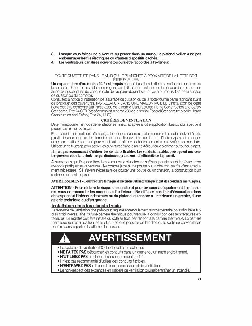
3. Lorsque vous faites une ouverture ou percez dans un mur ou le plafond, veillez à ne pas
4.
T
entre le bas de la hotte et la surface de cuisson ou
de cuisson ou du comptoir.Consultez la notice d'installation de la surface de cuisson ou de la hotte fournie par le fabricant avant de pratiquer des ouvertures. INSTALLATION DANS UNE MAISON MOBILE L'installation de cette
Construction and Safety, Title 24, HUD).
Installation dans les climats froids
-
CRITÈRES DE VENTILATION
passer par le mur ou le toit.
-
avant de pratiquer les ouvertures. Ne coupez jamais une poutre ou un chevron, sauf si c'est absolu-
renforcement est requise.
ATTENTION - Pour réduire le risque d'incendie et pour évacuer adéquatement l'air, assu-
des espaces à l'intérieur des murs ou du plafond, ou encore à l'intérieur d'un grenier, d'une galerie technique ou d'un garage.
• NE FAITES PAS• N'UTILISEZ PAS
• N'ENTRAVEZ PAS• Le non-respect des exigences en matière de ventilation pourrait entraîner un incendie.
AVERTISSEMENT!

22
FICHE TECHNIQUE ÉLECTRIQUE
-partiment des câblages externes.
INSTALLATION ÉLECTRIQUE AVEC BOÎTIER DE CÂBLAGES
National Fire Protection Association Batterymarch Park
(au niveau de l'appareil et de la boîte de liaison).
AVERTISSEMENT!

23
DIMENSIONS DE LA HOTTE
Min. 24"
24
10
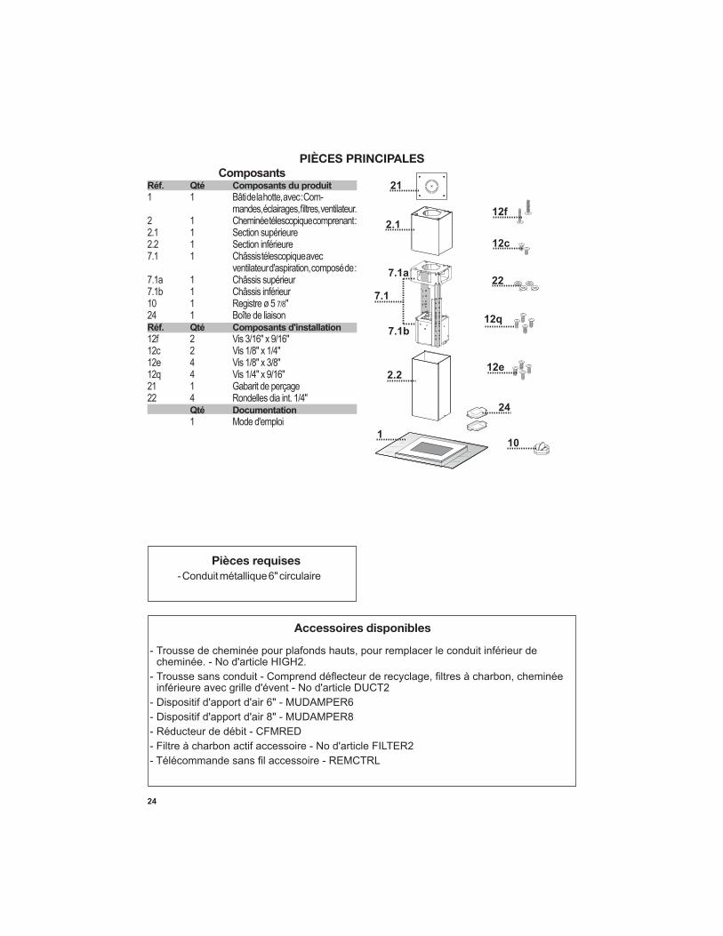
PIÈCES PRINCIPALES
1
2.2
2.1
21
7.1
12q
22
12c
12e
12f
24
7.1a
7.1b
Pièces requises
Accessoires disponibles
ComposantsRéf. Qté Composants du produit
1 1 Bâti de la hotte, avec : Com-
2 1 Cheminée télescopique comprenant : 2.1 1 Section supérieure2.2 1 Section inférieure 7.1 1 Châssis télescopique avec ventilateur d'aspiration, composé de : 7.1a 1 Châssis supérieur 7.1b 1 Châssis inférieur 10 1 Registre ø 5 7/8"24 1 Boîte de liaisonRéf. Qté Composants d'installation
12f 2 Vis 3/16" x 9/16" 12c 2 Vis 1/8" x 1/4"12e 4 Vis 1/8" x 3/8"12q 4 Vis 1/4" x 9/16"21 1 Gabarit de perçage 22 4 Rondelles dia int. 1/4" Qté Documentation
1 Mode d'emploi

25
6 "
Choisissez la méthode de canalisation
Sans canalisation - Option de recirculation
Options d'installation avec ventilation canalisée

26
1
Ø 10 mm
x4
216421
6
1 1/4"
AVERTISSEMENT!COMPTE TENU DE LA DIMEN-SION ET DU POIDS DE CETTE HOTTE, LE SOCLE DOIT ÊTRE
-FOND. Si le plafond est en plâtre ou en plaque de plâtre, le socle
cela n'est pas possible, une structure de soutien doit être construite derrière le plâtre ou la plaque de plâtre. Le fabricant ne peut être tenu responsable en cas de blessures ou de
mauvaise installation.

27
2 3
4
1
4MIN
740 mmMAX
940 mm
2
3
5
6
Si vous devez régler la hauteur du châssis, procédez comme suit :• Détachez les vis métriques qui unissent les deux
colonnes, situées sur les côtés du châssis (1, 2, 3, 4, 5, 6).
• Réglez le châssis à la hauteur requise, puis remettez en place toutes les vis enlevées comme ci-dessus.
de la cheminée et détachez-la du châssis inférieur. de la cheminée et détachez-la du châssis supérieur.
hotte

28
5 6
7
Le conduit supérieur de
avant de poursuivre l'installation
Pour installation avec ventilation canalisée
uniquement
Après avoir procédé au réglage de la hauteur, insérez la souche de cheminée supérieure à partir du haut et laissez-la sur le châssis.
Installez le registre inclus avec la hotte avant de la raccorder aux conduits.
Prenez ensuite les vis à bois ou boulons, selon votre installation, et vissez les 4 dans les trous d'implantation, en laissant 1/4" de la tête des vis libre.Installez ensuite un protège-câbles (homologation UL ou CSA) dans le boîtier de connexion de façon à pouvoir serrer les vis lorsque le socle de cheminée sera ancré au plafond.Soulevez ensuite le socle de cheminée à son em-placement, et faites passer le câble d'alimentation électrique à travers le protège-câbles.Placez le socle de cheminée de façon à aligner la grande ouverture des encoches en trou de
plafond. Poussez ensuite le socle de cheminée de façon à ce que les boulons s'engagent dans la partie étroite des encoches. Serrez fermement les quatre vis ou boulons.• Le montage du châssis doit être assez solide
pour supporter le poids de la hotte et tout stress causé par une pression latérale occasionnelle que pourrait subir l'appareil. Lorsque vous avez terminé, assurez-vous que la base est stable, même lorsque le châssis est plié.
• Dans tous les cas où le plafond n'est pas assez fort au point de suspension, l'installateur doit veiller à le renforcer à l'aide de plaques et de pièces de renfort ancrées à des pièces structurelles solides.

29
A. Home power supply cable
8
9
Réalisation des bran-chements
Retirez le couvercle du compartiment des câblages externes. NE METTEZ PAS l'alimentation sous tension avant d'avoir terminé l'installation! Branchez le câble d'alimenta-tion à la hotte.
jaune) de mise à la terre sous la vis de mise à la terre
hotte à l'aide d'un connecteur verrouillé par rotation.
-
l'aide d'un connecteur verrouillé par rotation.
Remettez le couvercle du com-partiment des câblages externes
A. Câble d'alimentation du réseau domestique
B. Fils noirs
D. Fils blancs
domestique branché à la vis de mise à la terre verte
F. Câble d'alimentation de la hotte
G. Câble d'alimentation de la hotte branché à la vis de
mise à la terre verte
enlevées précédemment.
Montage des cheminées supérieure et inférieure

30
11
10
Ductless installations require Ductless Conversion whose components are
. Do M
) for ductless The LOWER
(B should be
discarded and replaced by the new one with holes from
Ductless Conversion Kit
FIGURE
over the
into the FIGURE 12
châssis à l'aide des 2 vis enlevées précédemment.
Pour installation sans conduit uniquement
L'installation sans conduit nécessite une Trousse de conversion pour installation sans conduit dont les éléments sont représentés à la FIGURE 12. N'utilisez pas le REGISTRE pour l'installation sans conduit. L'HABILLAGE INFÉRIEUR DE CHEMINÉE doit être remplacé par celui présentant des trous de la Trousse de conversion pour installation sans conduit (D sur la FIGURE 12).
Tel qu'indiqué sur la FIGURE 12, placez le DÉFLECTEUR DE RECYCLAGE (A) sur l'ouverture d'évacuation du EASY CUBE (E). Placez les SORTIES HORIZONTALES DU DÉFLECTEUR DE RECYCLAGE (B) dans le DÉFLECTEUR (A).
31
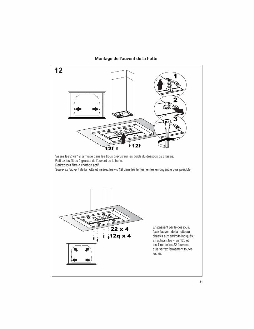
12
12q x 4
22 x 4
12f12f
1
2
3
Vissez les 2 vis 12f à moitié dans les trous prévus sur les bords du dessous du châssis.
Soulevez l'auvent de la hotte et insérez les vis 12f dans les fentes, en les enfonçant le plus possible.
En passant par le dessous,
châssis aux endroits indiqués, en utilisant les 4 vis 12q et les 4 rondelles 22 fournies, puis serrez fermement toutes les vis.
Montage de l'auvent de la hotte

32
13
14
12c x 2
Réalisation des branchements électriques internes

33
15
16
Pour option non canalisée avec recirculation d'air
à graisse de l'auvent de la hotte.
34
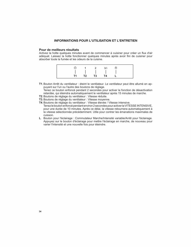
LT1 T2 T3 T4
INFORMATIONS POUR L'UTILISATION ET L'ENTRETIEN
T1 -
T2T3T4
L
Pour de meilleurs résultats

35
métalliques
d'utilisation, ou plus fréquemment en cas d'utilisation particulièrement intensive. Ils peuvent être lavés dans le lave-vaisselle.•
de l'appareil et en les tirant vers le bas simultanément.•
complètement avant de les remettre en place. (Si la
• Remettez-le en place, en vous assurant que la poignée se trouve vers l'avant.
actif
Il doit être remplacé environ tous les 4 mois d'utilisation, ou plus souvent en cas d'utilisation particulièrement intensive.•
de l'appareil et en les tirant vers le bas simultanément.•
• adéquat.
• Remettez-le en place, en vous assurant que la poignée se trouve vers l'avant.
Système d'éclairage • Les ampoules DEL doivent être remplacées par un
service d'entretien autorisé Faber.

36
Wiring Diagram
Dolce, Corrado
17-Feb-2016

37
4 janvier 2016
GARANTIE LIMITÉE ET SERVICE FABER
Tous les produits Faber font l'objet d'une garantie contre les défauts de matériel et de main-d'œuvre,accordée à l'acheteur original pour une période d'un (1) an à compter de la date d'achat initiale (preuve d'achat requise). Cette garantie couvre les frais de main-d'œuvre et les pièces de rechange. À sa discrétion, Faber peut réparer ou remplacer le produit ou les composants nécessaires à remettre le produit en bon état de marche. Pour bénéficier de services prévus par la garantie, veuillez communiquer avec le détaillant auprès duquel vous avez acheté la hotte de cuisine, ou encore avec le distributeur Faber de votre région. Si vous n'êtes pas en mesure de localiser un distributeur Faber dans votre région, veuillez communiquer avec nous au 508-358-5353 pour connaître le nom d'un distributeur à proximité.
Les éléments suivants ne sont pas visés par la garantie Faber :
1. Les appels au service de réparation visant à corriger l'installation de la hotte de cuisine, à recevoir des instructions sur l'utilisation de la hotte de cuisine, le remplacement ou la réparation des fusibles du domicile ou la correction des câblages ou de la plomberie du domicile. 2. Les appels au service de réparation visant à réparer ou remplacer les ampoules électriques de hotte, les fusibles ou les filtres. Ces pièces consommables ne sont pas couvertes par la garantie. 3. Les réparations si votre hotte de cuisine est employée à des fins autres que celles prévues, soit l'utilisation résidentielle normale pour une famille. 4. Les dommages découlant d'un accident, d'une modification, de l'utilisation incorrecte ou abusive, d'un incendie, d'une inondation, d'un cas de force majeure, d'une installation inadéquate, d'une installation non conforme aux codes en matière d'électricité ou de plomberie ou à la documentation fournie par Faber, ou encore d'une utilisation du produit non approuvée par Faber. 5. Les frais de main-d'œuvre ou de remplacement des pièces pour les appareils utilisés à l'extérieur des États-Unis ou du Canada, y compris toutes les hottes de cuisine Faber non-UL ou C-UL homologuées. 6. Les réparations à la hotte découlant de modifications non autorisées apportées à la hotte de cuisine. 7. Les frais encourus pour les déplacements et le transport de produits en région éloignée et les frais de cueillette et livraison. La réparation des hottes de cuisine Faber doit être réalisée à domicile.
LA PRÉSENTE GARANTIE NE PRÉVOIT AUCUNE FORME DE DÉDOMMAGEMENT EN CAS DE DOMMAGES ACCESSOIRES OU
CONSÉCUTIFS, Y COMPRIS, SANS TOUTEFOIS S'Y LIMITER, LES DOMMAGES DIRECTS, INDIRECTS, ACCESSOIRES,
PARTICULIERS OU CONSÉCUTIFS, LES LÉSIONS CORPORELLES/MORTELLES OU LA PERTE DE PROFITS. LA GARANTIE
OFFERTE PAR FABER EST LIMITÉE AUX CONDITIONS ÉNONCÉES CI-DESSUS ET À LA PÉRIODE DE GARANTIE INDIQUÉE
DANS LES PRÉSENTES ET EST EXCLUSIVE. SAUF DISPOSITIONS EXPRESSES CONTRAIRES DANS LE PRÉSENT ACCORD,
FABER DÉCLINE TOUTE CONDITION, REPRÉSENTATION OU GARANTIE EXPLICITE OU IMPLICITE, Y COMPRIS, SANS
TOUTEFOIS S'Y LIMITER, TOUTE GARANTIE IMPLICITE DE QUALITÉ MARCHANDE OU D'ADAPTATION À UN USAGE
PARTICULIER.
Les droits qui vous sont conférés en vertu de la présente garantie peuvent varier d'une province ou d'un État
à l'autre.
No de modèle : ______________________________ No de série : _____________________________

38

39