Embed Size (px)
Citation preview

InstallationGuide
System Overview, Components, Tools & Accessories,Construction Process, Installation Procedures, Bracing, Core Filling
December 2017

2
2017 2017
Legal statements
Important legal statementsReasonable efforts have been made to ensure the accuracy of this publication; however, any information or data contained herein is subject to change without notice. To ensure the information you are using is correct, AFS recommends you review the latest technical information available on the AFS website www.afsformwork.com.au, or alternatively call 1300 727 237 to speak to a Technical Representative.
The AFS logo and rediwall® mark are registered trade marks.© 2017 AFS SYSTEMS PTY LTD. No part of this publication may be reproduced in any form or by any means without prior written permission from AFS Systems Pty Ltd. All rights reserved.
Disclaimer
1. It is the responsibility of the user to ensure that the use of this manual is appropriate and to exercise their own judgment when using this manual.
2. AFS does not accept any responsibility (whether for negligence or otherwise) for any consequence arising from the use or application of this manual.
3. AFS reserves the right to change the specification of this manual without notice.
4. Please check with AFS that you have the latest version as the manual may be updated from time to time and certain details may change.
5. This declaimer applies to the extent permitted by law.

3
2017 2017
TABLE OF CONTENTS
Legal statements ................................................................................................................................ 2
Disclaimer ........................................................................................................................................... 2
INTRODUCTION � � � � � � � � � � � � � � � � � � � � � � � � � � � � � � � 4
SYSTEM OVERVIEW � � � � � � � � � � � � � � � � � � � � � � � � � � � � � 5Rediwall® Applications & Solutions ..................................................................................................... 6
Rediwall® Product Description ............................................................................................................ 8
Rediwall® System Benefits ................................................................................................................. 8
COMPONENTS, TOOLS & ACCESSORIES � � � � � � � � � � � � � � � � � 9Components for RW110C System ...................................................................................................... 9
Components for RW156C-Panel System .......................................................................................... 11
Components for RW200C-Panel System .......................................................................................... 13
Components for RW256S Slide System ........................................................................................... 15
Tools & Accessories ......................................................................................................................... 16
THE CONSTRUCTION PROCESS � � � � � � � � � � � � � � � � � � � � � �19Construction Process Overview ........................................................................................................ 19
Ordering ........................................................................................................................................... 22
How to order .................................................................................................................................... 22
CONSTRUCTION AND INSTALLATION PROCEDURES � � � � � � � � � �23Introduction ...................................................................................................................................... 23
Component Delivery & Worksite Layout ............................................................................................ 24
Floor/Wall Junction – Floor Track Installation ..................................................................................... 25
Starting Location .............................................................................................................................. 27
Corner Construction ......................................................................................................................... 28
Wall Construction ............................................................................................................................. 29
Corner Reinforcement ...................................................................................................................... 30
Corner Reinforcement - alternate method ......................................................................................... 31
Wall Construction ............................................................................................................................. 32
Safety Rail/Balustrade Wall Installation .............................................................................................. 33
Steel Reinforcement Installation ........................................................................................................ 34
T Junction Construction.................................................................................................................... 35
Obtuse Corner Construction ............................................................................................................. 36
H Joiner Installation .......................................................................................................................... 38
H-Joiner Installation (Limited Site Access) ......................................................................................... 39
Accessory Extensions ....................................................................................................................... 40
End Cap Installation .......................................................................................................................... 41
RW256S Blade Wall ......................................................................................................................... 42
Rediwall® Edge Form ....................................................................................................................... 43
Rediwall® J-Track Installation ............................................................................................................ 44
Window Openings ............................................................................................................................ 45
Doorway & Lintel Installation ............................................................................................................ 47
Wide Radius Curved Wall Installation ................................................................................................ 50
Curved Wall Reinforcement Bar Installation ....................................................................................... 51
Stairway Landing Construction ......................................................................................................... 52
Retention Tank Construction & Tanking ............................................................................................. 53
Lift Pit ............................................................................................................................................... 54
Installation of Services ...................................................................................................................... 55
Penetrations ..................................................................................................................................... 56
REDIWALL® TEMPORARY CONSTRUCTION BRACING � � � � � � � � � �58Bracing of Walls ................................................................................................................................ 59
CORE FILLING OF WALLS � � � � � � � � � � � � � � � � � � � � � � � � � �67

4
2017 2017
INTRODUCTION
Backed by one of Australia’s most trusted brandsAFS Systems is a division of CSR Building Products Limited, one of Australia's leading building products companies.
We form part of CSR's portfolio of trusted brands - amongst some of the biggest names in the Australasian building products industry.
Our innovative afs logicwall® fibre cement, and afs rediwall® pvc permanent formwork walling systems have enabled the speedy and cost-efficient installation of load-bearing walls across a range of projects including multi-residential, hotels, aged care facilities, shopping centres and student accommodation.
No matter what the application from the basement right through to the penthouse, we have a comprehensive walling solution to meet the demands of any project as only AFS is able to offer you the versatility of both a fibre cement or pvc walling solution.
Our rediwall® pvc system’s extruded components simply snap or slide together to create a concrete formwork erected with maximum efficiency. Rediwall® requires almost no machinery-aided installation. In fact, installations can be undertaken without the need for any detailed training. And with its high quality semi-gloss finish it requires no additional finishing for most applications.
Suitable as a tough load bearing solution for building subterranean structures such as basements and retention tanks, it can also be utilized for above ground applications such as party walls, columns and retaining walls, making it a truly versatile solution.

5
2017 2017
SYSTEM OVERVIEWAFS Rediwall® systems provide loadbearing wall solutions for residential or commercial structures and multi storey buildings. These systems can be used for both above and below ground structures. The rediwall®
Note: If rediwall® is exposed to UV, appropriate protective finish shall be applied.
Up to 7.5m height (continuous profile) loadbearing walls
Lintels
Sills
Floor/slab/landing/stair engagement
Slab-to-slab multi storey loadbearing walls
Below ground basement/ sub floor construction
Blade Wall
Balustrades
Optional board lining of walls on batten framing
Door & Window openings
PVC faces require no finishing
systems are highly modular, providing architects and engineers the freedom to design buildings to suit various applications.
6
2017 2017
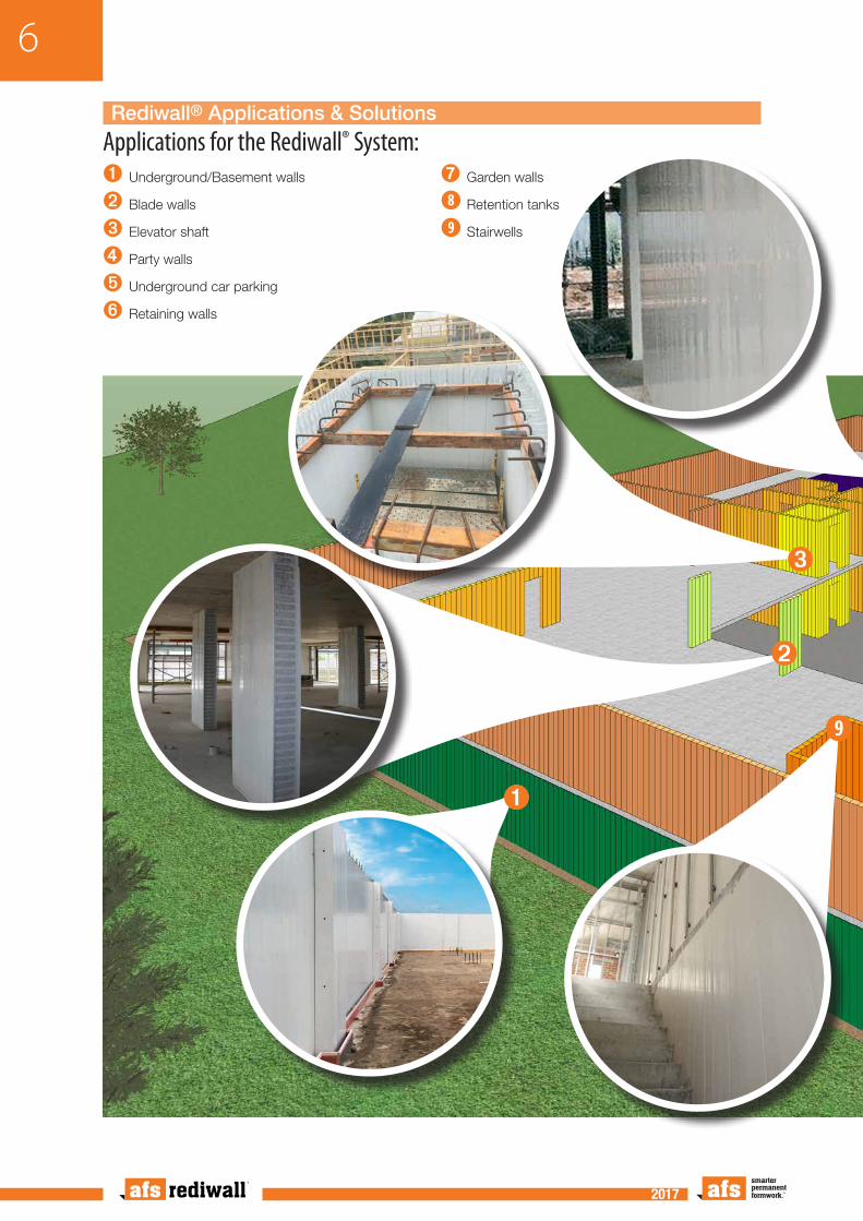
Applications for the Rediwall® System:➊ Underground/Basement walls
➋ Blade walls
➌ Elevator shaft
➍ Party walls
➎ Underground car parking
➏ Retaining walls
➐ Garden walls
➑ Retention tanks
➒ Stairwells
➌
Rediwall® Applications & Solutions
➊
➋
➒

7
2017 2017
➎
➏
➐
➑
➍

8
2017 2017
Rediwall® Product Description
Rediwall® consists of extruded rigid PVC components that serve as a permanent formwork for cast in-situ concrete walls for a large range of applications. The extruded components slide and snap together to create a PVC formwork that remains in place after the concrete is poured and cured, providing a low maintenance, finished wall surface.
The AFS Rediwall® system allows for the panels to be installed from the concrete slab which accommodates the vertical walls being built prior to the horizontal formwork being installed
The available rediwall® types are identified in the following table:
TABLE A1: Rediwall® Systems Overview
AFS Rediwall®OVERALL
THICKNESS (NOMINAL)
CONCRETE CORE
(INTERNAL CAVITY)
FILLED MASS(KG/M2)
UNFILLED MASS (KG/M2)
PVC WALL THICKNESS
(MM)
Clip System
RW110C 110mm 105mm 260 11.18 2.5
RW156C 156mm 151mm 375 11.12 2.5
RW200C 200mm 195mm 480 12.49 2.5
Slide System RW256S 256mm 251mm 620 17.12 2.5
Rediwall® System Benefits
With an increasing demand throughout the construction industry for faster and more efficient building methods, rediwall® has gained rapid acceptance in the market place due to the range of benefits it offers developers, designers and builders, including:
• Cost efficiency
• Speed of construction
• Ease of installation and materials handling
• Low maintenance and aesthetically appealing finish
• NCC compliant
• Water resistant
• Design versatility

9
2017 2017
Components for RW110C System
RW110C Panel Description
66.6mm
66.6mm
27.4mm
66.6mm250mm
Female
Male
259mm
110mm
An extruded PVC panel used to form the main body of a wall. Adjoining panels are fitted using the male to female clip-in system. Each panel is extruded to a surface tolerance of 1.5mm. Has 4 internal webs with oval holes for single reo bar placement. For m2 calculation, face width is 250mm.
RW110C Corner Assembly Description
110mm
135mm
135mm110mm
A three piece PVC panel that forms a corner between walls meeting at 90º. Designed to allow for removal of the outside 90º corner cap for easy placement and inspection of internal reinforcement. Cap is refitted for concrete filling. Adjoining panels are fitted using the male to female clip-in system.
Floor Track Description
117mm
30mm
A PVC track used to set the bottom line of the wall. Laid flat, the floor track has large holes for starter bars, etc. The sides are for both locating the panels and for screw fixing to the bottom of the panels.
T joiner Description
12mm
110mm
A PVC extrusion used to start a T-wall from a through wall, where the T-wall is close to 90º. Fixed vertically to the face of the through wall. Has holes in its face to assist alignment when drilling the through wall for reo bar placement. Adjoining panels are fitted using the male to female clip-in system.
COMPONENTS, TOOLS & ACCESSORIES

10
2017 2017
H joiner Description
100mm
117mm
A slide-on PVC extrusion.
Primarily used horizontally on external walls where it is laid along the straightened top of panels to act as a bottom track for the next level of panels.
Also used vertically as a wall make-up piece. Can be slid into a gap in the wall of 50mm or less and screw fixed to adjoining panels.
Slide on End Cap Description
117mm
30mm
A slide-on PVC extrusion for capping off wall ends and openings. Fixed on each side with screws and/or glue. Can be installed before or after wall is filled. Adequate bracing must be provided.
Fibre Cement End Cap Description
9mm
103mm
A fibre cement strip, for closing off wall ends, where a simple shutter is required. Cut to length on-site, the strip slides in behind the web of an end panel. Can also be use as a pour break. Adequate bracing must be provided.

11
2017 2017
Components for RW156C-Panel System
RW156C Panel Description
250mm
156mm
66.6mm
66.6mm
66.6mm
27.4mm
259mm
Female
MaleAn extruded PVC panel used to form the main body of a wall. Adjoining panels are fitted using the male to female clip-in system. Each panel is extruded to a surface tolerance of 1.5mm. Has 4 internal webs with oval holes for single reo bar placement. For m2 calculation, face width is 250mm.
RW156C Corner Assembly Description
156mm180mm
156mm
180mm A Three piece PVC panel that forms a corner between walls meeting at 90º. Designed to allow for removal of the outside 90º corner cap for easy placement and inspection of internal reinforcement. Cap is refitted for concrete filling. Adjoining panels are fitted using the male to female clip-in system.
115mm Spacer Description
115mm 66.6mm
156mm
An extruded PVC panel used to adjust the length of a wall. Adjoining panels are fitted using the male to female clip-in system. Used primarily close to the closure of a wall, Has 2 internal webs with oval holes for single reo bar placement. For m2 calculation, face width is 115mm.
Floor Track Description
30mm
163mm
A PVC track used to set the bottom line of the wall. Laid flat, the floor track has large holes for starter bars, etc. The sides are for both locating the panels and for screw fixing to the bottom of the panels.

12
2017 2017
J Track Description
100mm50mm
164mm
A slide-on PVC extrusion primarily used horizontally on external walls where an edge-form slab is to be formed. It is laid along the straightened top of panels to act as a bottom track for the next level of panels and to assist with edge-form preparation.
H Joiner Description
100mm
164mm
A slide-on PVC extrusion primarily used horizontally on external walls where it is laid along the straightened top of panels to act as a bottom track for the next level of panels.
Also used vertically as a wall make-up piece. Can be slid into a gap in the wall of 50mm or less and screw fixed to adjoining panels.
T Joiner Description
156mm
12mm
A PVC extrusion that is fixed vertically to the face of a through wall to start a T-wall, where the T-wall is close to 90º. Has holes in its face to assist alignment when drilling the through wall for reo bar placement. Adjoining panels are fitted using the male to female clip-in system.
Slide on End Cap Description
30mm
163mm
A slide-on PVC extrusion for capping off wall ends and openings. Fixed on each side with screws and/or glue. Can be installed before or after wall is filled. Adequate bracing must be provided.
Fibre Cement End Cap Description
9mm
149mm
A fibre cement strip, for closing off wall ends, where a simple shutter is required. Cut to length on-site, the strip slides in behind the web of an end panel. Can also be use as a pour break. Adequate bracing must be provided.

13
2017 2017
Components for RW200C-Panel System
RW200C Panel Description
250mm
200mm
66.6mm
27.4mm
66.6mm
22.8mm
66.6mm 259mm
Female
Male
An extruded PVC panel used to form the main body of a wall. Adjoining panels are fitted using the male to female clip-in system. Each panel is extruded to a surface tolerance of 1.5mm. Webs have kidney shaped holes for single, or double reo bar placement by inverting the panel. Holes must be kept in horizontal alignment. For m2 calculation, face width is 250mm.
Corner Assembly Description
200mm225mm
200mm
225mmA three piece PVC panel that forms a corner between walls meeting at 90º. Designed to allow for removal of the outside 90º corner cap for easy placement and inspection of internal reinforcement. Cap is refitted for concrete filling. Adjoining panels are fitted using the male to female clip-in system.
115mm Spacer Description
115mm
200mm
66.6mm
An extruded PVC panel used to adjust the length of a wall. Adjoining panels are fitted using the male to female clip-in system. Used primarily close to the closure of a wall. Has 2 internal webs with kidney shaped holes for single, or double reo bar placement by inverting the panel. For m2 calculation, face width is 115mm.
Floor Track Description
30mm
207mm
A PVC track used to set the bottom line of the wall. Laid flat, the floor track has large holes for starter bars, etc. The sides are for both locating the panels and for screw fixing to the bottom of the panels.
J Track Description

14
2017 2017
100mm
208mm
A slide-on PVC extrusion primarily used horizontally on external walls where an edge-form slab is to be formed. It is laid along the straightened top of panels to act as a bottom track for the next level of panels and to assist with edge-form preparation.
H Joiner Description
100mm
207mm
A slide-on PVC extrusion.
Primarily used horizontally on external walls where it is laid along the straightened top of panels to act as a bottom track for the next level of panels.
Also used vertically as a wall make-up piece. Can be slid into a gap in the wall of 50mm or less and screw fixed to adjoining panels.
T Joiner Description
12mm
200mm
A PVC extrusion that is fixed vertically to the face of a through wall to start a T-wall, where the T-wall is close to 90º. Has holes in its face to assist alignment when drilling the through wall for reo bar placement. Adjoining panels are fitted using the male to female clip-in system.
Slide on End Cap Description
30mm
207mm
For capping off wall ends and openings. A slide on connection with a 40mm side for fixing with screws or glue. Can be installed before or after wall is filled. Must be propped when filling, if a flat end is required.
Fibre Cement End Cap Description
9mm
193mm
A fibre cement strip, for closing off wall ends, where a simple shutter is required. Cut to length on-site, the strip slides in behind the web of an end panel. Can also be use as a pour break. Adequate bracing must be provided.

15
2017 2017
Components for RW256S Slide System
RW256S Panel Description
150mm73.5mm
256mm
An extruded PVC panel used to form the main body of a wall. Adjoining panels are fitted using the male to female slide in coupling system. Each panel is extruded to a surface tolerance of 1.5mm. Webs have ‘square’ holes to accept double reo with appropriate concrete cover. Panels are joined by male to female slide in coupling. For m2 calculation, face width is 150mm.
Floor Track Description
30mm
264mm
A PVC track used to set the bottom line of the wall. Laid flat, the floor track has large holes for starter bars, etc. The sides are for both locating the panels and for screw fixing to the bottom of the panels.
Female/Female Joiner Description
42mm
256mm
An extruded PVC joiner used to reverse a male panel end to a female panel end. For m2 calculation, face width is 42mm.
End Cap Description
22mm
256mm
A slide-on PVC extrusion for capping off wall ends and openings. Adequate bracing must be provided.
Fibre Cement End Cap Description
9mm
248mm
A fibre cement strip, for closing off wall ends, where a simple shutter is required. Cut to length on-site, the strip slides in behind the web of an end panel. Can also be use as a pour break. Adequate bracing must be provided.

16
2017 2017
Tools & Accessories
Screws Description
Button head stitching screw 10G x 25mm, for joining of rediwall® components.
Sealant Description
Sealant used under floor track and other locations where required.
Wall Brace Description
Adjustable wall bracing is available from AFS for purchase or hire. Contact AFS for further information.

17
2017 2017
Personal Protective Equipment The Personal Protective Equipment required may vary from site to site and from time to time, and it is the responsibilty of every individual to ensure that they use the appropriate equipment to safeguard themselves and those around them.
A basic protective kit should include, but not necessarily be limited to:
• Dust mask
• Safety gloves
• Hearing protection
• Sunscreen cream/lotion
• Eye protection
Hand Tools RequiredTo safely and efficiently complete any task, it is essential to have the necessary tools available and to use the right tool for the right task.
A typical range of hand tools would include, but not be limited to the following:
• Tool bag/belts
• Cutting knife
• Handsaws
• Hammers - ‘claw’ and ‘gympie’
• Pencils, marking pens, chalk
• Variety of pliers
• A range of squares
• String and chalk lines
• Tape Measures – eg. 8m and 3m
• Spirit levels – range of lengths eg. 600mm and 2000mm
• Plumb Bob
• Laser leveling equipment
Access ToolsAll scaffolding and safe access provisions are the responsibility of the builder and installers and are governed by the individual site conditions. It is essential that safe work practices and all associated standards are met/complied with. Installers would normally provide a range of ladders and/or platforms for personal access to the top of wall panels for the fitting of braces and checking of stringlines.

18
2017 2017
• A ‘charge gun', such as the ‘Hilti GX120’ with appropriate fixings to pin the floor track to the concrete slab.
• A screw driver gun, with appropriate driver bits and screws for fixing rediwall® panels to track and adjacent panels or form deck. Also used to fixing bracing.
• A range of grinders and circular saws for cutting components and timbers for bracing.
Hilti GX120
Power ToolsThere are a range of power tools required during installation of afs rediwall®. Wherever possible preference should be given to cordless tools.
Note: All power tools require tagging as per site requirements.
Suggested power tools and applications include:
Concrete Pouring & Finishing Tools• Concrete pouring and finishing tools,
including:
– At least one wheelbarrow, multiple shovels and a range of trowels.
– Concrete vibrator: 40mm diameter maximum.
19
2017 2017
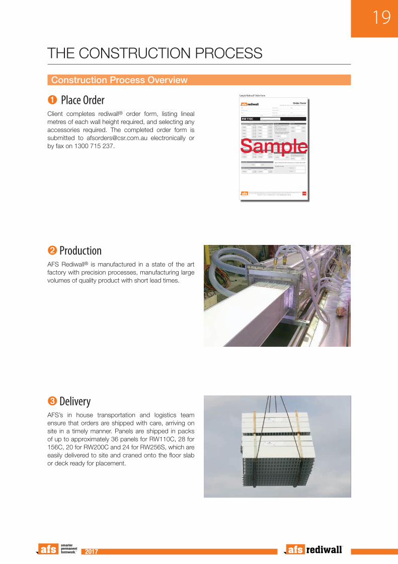
Construction Process Overview
➊Place OrderClient completes rediwall® order form, listing lineal metres of each wall height required, and selecting any accessories required. The completed order form is submitted to [email protected] electronically or by fax on 1300 715 237.
Speedy-Snap-InTM Wall Panels Tick your RW size
Ezy-FitTM 90º Corners Tick your RW size
AFS will price on receipt of your entries in metres/height
All prices exclude GST. Lead times from confirmation of your order: an AFS customer service representative will confirm lead times for your order. A surcharge may apply for orders under 125m2
and/or for crane truck delivery. AFS will not accept return of left-over product that has been approved and signed for by the customer. AFS Standard Terms & Conditions of Sale apply to this order(copy available upon request). Quantity of floortrack ordered over and above the lineal metres (L/M) of wall panel ordered will be charged out @ $8.50/LM.
Questions? Call us on 1300 727 237 or email [email protected]
Lineal Metres Height (m) Lineal Metres Height (m)
T-Joiner Tick your RW size
H-Joiner Tick your RW size
110mm 110mm
110mm 110mm
110mm 110mm
110mm 110mm
110mm
Quantity
110mm
Quantity
110mm 110mm
ABN:
Company name:
Email:
Site contact: Phone:
Order number: Date:
Delivery address:
Delivery date: Time:
Delivery: £ Pickup from AFS, Minto or delivery via £ Semi £ Rigid £ Rigid/crane
Quantity
110mm
110mm
Quantity
Quantity Quantity
110mm
110mm
£ x 2.8m £ x 3.2m
£ x 2.8m £ x 3.2m
£ x 2.8m £ x 3.2m
£ x 2.8m £ x 3.2m
£ x 2.8m £ x 3.2m
£ x 2.8m £ x 3.2m
£ x 2.8m £ x 3.2m
£ x 2.8m £ x 3.2m
£ x 2.8m £ x 3.2m
£ x 2.8m £ x 3.2m
£ x 2.8m £ x 3.2m
£ x 2.8m £ x 3.2m
£ x 2.8m £ x 3.2m
£ x 2.8m £ x 3.2m
£ x 2.8m £ x 3.2m
£ x 2.8m £ x 3.2m
Squint Angles For non-90° corners
x 3m
Included in your m2 pricing
Quantity
Order Formv1
Call 1300 727 237 or email: [email protected]
ABN 45 576 072 788
How many boxes?
£ No screws required Tick to select
Screws 25mm screws • 1,000 per box
Fibre Cement Strip
Additional to your m2 pricing
Braces
Braces charged on delivery at $60 (each) and credited at $40 (each) upon return
Waterstop
Floortrack
£ PVC floortrack £ Floor angle
Total m2
Extras
Upon receipt we will contact you to confirm this order
x 3m110mm
End Caps
x 3mQuantity
How many metres?$12 per lineal metre
AFS office use only:
x 2.8m110mm
110mm
x 3.2m110mm
Tick choice:
Metres of floortrack additional to that included in your m2?
Floortrack is included in your m2
unless: (tick choice)
£ Yes, floortrack required£ No floortrack required
RW 110C Page of
110mm 110mm£ x 2.8m £ x 3.2m
£ x 2.8m £ x 3.2m
Quantity
Quantity
Sample Rediwall® Order Form
Sample
➋ ProductionAFS Rediwall® is manufactured in a state of the art factory with precision processes, manufacturing large volumes of quality product with short lead times.
➌ DeliveryAFS’s in house transportation and logistics team ensure that orders are shipped with care, arriving on site in a timely manner. Panels are shipped in packs of up to approximately 36 panels for RW110C, 28 for 156C, 20 for RW200C and 24 for RW256S, which are easily delivered to site and craned onto the floor slab or deck ready for placement.
THE CONSTRUCTION PROCESS

20
2017 2017
Construction Process Overview – Continued
➍ Site ErectionOnce set-out is complete, rediwall® floor track is installed, followed by the rediwall® panels being lifted into place by hand over the reinforcement starter bars. In some cases it is simply installed off the formwork deck of the next floor level. The panels are then braced using temporary bracing or fixed to the formwork deck.
➎ Openings & ServicesSmaller penetrations may be cut out once the formwork is installed and then capped off using the rediwall® End Cap. Doorway and window openings are formed using sill and lintel panels which can be supplied cut to size. Steel door frames can be installed to suit, or the openings can simply be capped off using the rediwall® End Cap.
➏ Concrete Core FillThe erected panels are then core filled with concrete using a mix design that is suitable for filling rediwall®, via a concrete pump. This is mostly done from the formed deck of the next slab or off a scaffold. Refer to concrete core fill procedure.

21
2017 2017
Construction Process Overview – Continued
➐ Finishing of WallsOnce the concrete core fill has gained strength and the walls are permanently braced by the floor or roof structure at the top of the walls, the temporary bracing is removed. The smooth, off white finish of the rediwall® panels is a suitable finish for many applications, however suitable paints or acrylic renders can be applied to the surface if required. Please contact Dulux Acratex or equivalent acrylic render suppliers, for their warranted specifications on the rediwall® substrate.

22
2017 2017
Ordering
Ordering of rediwall® is a simple process requiring a rediwall® Order Form to be completed by the appropriate project personnel and submitted to the rediwall® production team.
A sample of the form is shown below. An interactive PDF form can be downloaded from w w w. a f s f o r m w o r k . c o m . a u / re d i w a l l - o rd e r-form completed digitally and then emailed to – [email protected]
Alternatively a printable form can be downloaded at www.afsformwork.com.au/rediwall-order-form completed and returned by email as above or faxed to 1300 715 237.
Lengths and heights of walls, derived from project
construction drawings, are inserted into the rediwall® order form along with the quantities of accessories, such as: corners, end caps, floor track and H-sections.
To avoid delays during erection, it is recommended that additional rediwall® components are ordered. Additional quantities ordered should be based on project size, construction schedule, site proximity to the rediwall® supply facility, the potential for damage on site and the potential for site modifications.
On completion and submission of your order form you will receive a confirmation detailing exactly what has been entered into the production system. It is the customers responsibility to check this confirmation for accuracy and advise AFS of any errors immediately.
Speedy-Snap-InTM Wall Panels Enter your RW size
Ezy-FitTM 90º Corners Tick your RW size
AFS will price on receipt of your entries in metres/height
All prices exclude GST. Lead times from confirmation of your order: an AFS customer service representative will confirm lead times for your order. A surcharge may apply for orders under 125m2
and/or for crane truck delivery. AFS will not accept return of left-over product that has been approved and signed for by the customer. AFS Standard Terms & Conditions of Sale apply to this order(copy available upon request). Quantity of floortrack ordered over and above the lineal metres (L/M) of wall panel ordered will be charged out @ $8.50/LM.
Questions? Call us on 1300 727 237 or email [email protected]
T-Joiners
H-Joiners Tick your RW size
110mm
Quantity
110mm
Quantity
110mm 110mm
ABN:
Company name:
Email:
Site contact: Phone:
Order number: Date:
Delivery address:
Delivery date: Time:
Delivery: £ Pickup from AFS, Minto or delivery via £ Semi £ Rigid £ Rigid/crane
Quantity
110mm
110mm
Quantity
110mm
110mm
£ x 2.8m £ x 3.2m
£ x 2.8m £ x 3.2m
£ x 2.8m £ x 3.2m
£ x 2.8m £ x 3.2m
£ x 2.8m £ x 3.2m
£ x 2.8m £ x 3.2m
£ x 2.8m £ x 3.2m
£ x 2.8m £ x 3.2m
Squint Angles For non-90° corners
x 3m
Included in your m2 pricing
Quantity
Order Formv4
Call 1300 727 237 or email: [email protected]
ABN 45 576 072 788
Fibre Cement Strip
Additional to your m2 pricing
Braces
Braces charged on delivery at $60 (each) and credited at $40 (each) upon return
Floor Track
£ PVC floor track £ Floor angle
Total m2
Extras
Upon receipt we will contact you to confirm this order
x 3m110mm
End Caps
x 3mQuantity
AFS office use only:
x 2.8m110mm
110mm
x 3.2m110mm
Tick choice:
Metres of floor track additional to that included in your m2?
Floor track is included in your m2
unless: (tick choice)
£ Yes, floor track required£ No floor track required
RW 110C Page of
Quantity
Quantity
x 3.2m110mm
Quantity
Lineal Metres Height (m) Lineal Metres Height (m)
110mm 110mm
110mm 110mm
110mm 110mm
110mm 110mm
How many boxes?
£ No screws required Tick to select
Screws 25mm screws • 1,000 per box
Sample Rediwall® Order Form
SampleHow to order
➊C o m p l e t e y o u r company details, make
sure to include the correct site contact details.
➋Complete your order n u m b e r, d e l i v e r y
address and your requested delivery date.
➌Calculate the total linear metres required
and the height of the panels you require. All accessories are supplied at stock length.
➍Add quant i t ies of Squint Angles and T
junctions if required.
➎ Select your floor track option and quantity.
➏Enter the quantity of end caps, screws,
braces and fibre cement strips you will need.
➐ Submit your form and AFS will contact you
for order confirmation before processing your order. Check the confirmation email from AFS for accuracy.

23
2017 2017
This Installation Procedure Section has been prepared by AFS Systems Pty Ltd to assist builders, engineers and architects to understand the construction procedures for loadbearing and retaining walls using rediwall®.
The Installation Section provides information on the following aspects of construction using rediwall®:
• Ordering
• Delivery
• Wall set-out
• Establishing installation starting point
• Floor track/floor angle installation
• Installation of 90° corner
• Screw fixing of panels to floor track
• Installation of corner reinforcement
• Horizontal reinforcement placement
• Vertical reinforcement placement
• End caps
• Curved walls
• Tanking
• Bracing
Introduction
Although every effort has been made to ensure that all the information provided in this Installation manual is factual and consistent with good practice, AFS does not assume any liability for errors or oversights resulting from the use of information contained in this manual.
AFS highly recommends that the entire construction team are fully aware of the construction order and methods prior to commencement of wall installation.
Rediwall® consists of extruded rigid polymer components that serve as a permanent formwork for concrete walls in loadbearing and retaining applications. Popular uses include basement walls, retaining walls, retention tanks, foundation and landscaping walls, blade walls etc. The extruded components connect together to create formwork that remains in place after the concrete is poured and cured. This combination results in a strong concrete core wall with a low maintenance, finished wall surface.
Four rediwall® systems are available as shown in TABLE B1.
TABLE B1: Rediwall® Systems Overview
Rediwall® SYSTEMWALL THICKNESS
OVERALL (NOMINAL) CONCRETE CORE
RW110C 110mm 105mm
RW156C 156mm 151mm
RW200C 200mm 195mm
RW256S 256mm 251mm
Note: Concrete core thickness is calculated including manufacturing tolerance.
CONSTRUCTION AND INSTALLATION PROCEDURES

24
2017 2017
Component Delivery & Worksite Layout
Transport to site is typically arranged by AFS. Rediwall® packs are unloaded by a crane or forklift (provided by the builder), or crane truck (if requested at point of sale). Customers can also pick up with their own transport if prearranged. On delivery of the rediwall® components, place the packs strategically around the area where it is to be installed to minimise manual handling. Placement of packs should not interfere with locations for temporary wall bracing required during construction.
Rediwall® panels from 600mm to 7.5m can be supplied at the requested custom heights, suited to the specific project requirements and are listed on the delivery docket received with each delivery.
Using the pins/markings provided by the surveyor and the construction drawings, ensure the walls are clearly and accurately set-out. The builder should be responsible for this and should sign off on the set-out prior to commencement.

25
2017 2017
Rediwall® PVC Floor Track
➊Starter bars should be set into the concrete as per engineering specifications. Corner bars should be set in the middle of the rediwall® corner profile.
➋Mitre the ends of the floor track
so that the corner joins neatly.
➌Two beads o f polyurethane
sealant (e.g. Sikaflex 221 or Bostik Seal & Flex) or as per waterproofers details, must be applied in accordance wi th the manu fac tu re r ' s instructions under the rediwall® floor track (one on each side of the track) on all external walls, and any portion of a wall that separates or adjoins a wet area (e.g. bathroom, kitchen, or laundry).
➍Rediwall® floor track is then placed in the required location and fixed to the concrete footing or slab using a masonry fixing gun or drill and anchor masonry
fixing system. Fix with fasteners each side of the track at 500mm centres for walls up to 5m height, or at 250mm maximum centres for walls over 5m height.
Floor/Wall Junction – Floor Track Installation
➊
IntroductionAttention must be paid to the specified detailing of the horizontal slab/wall joint. Some projects have specific waterproofing requirements, such as installation of expandable Waterstop at the slab to wall junction.
WARNING: Rediwall® panels cannot be moved without demolition once filled with concrete.
Base Restraint1. A continuous horizontal member is required at the base of the wall on at least one side of the rediwall® panels to hold the members straight and to prevent movement during core filling. This member is typically PVC floor track, however 40 x 40mm PVC angle installed on one side of the wall is acceptable.
2. The bottom restraining member may also act as formwork to cover any gaps at the underside of the wall due to irregularities in the surface of the footing or slab.
3. The bottom restraining member is to be fixed to the rediwall® components and anchored to the foundation as required by the Project Engineer's specifications.
4. Bottom restraining members fitted on one side of the wall are to be connected to the wall at 500mm maximum centres. For walls over 5m in height, the connection to the wall is to be at 250mm maximum centres.
➍
➋
➌

26
2017 2017
Water Treatment of Cold JointsAll waterproofing details are to be completed by the Project Builder and waterproofing contractor. When filled with concrete, rediwall® is a water resistant wall system. However specific areas requiring waterproofing details include horizontal concrete cold joints, and where water can track down along panel joints.
Any required waterproofing products must be installed strictly in accordance with the particular manufacturer's instructions.
➊Install afs rediwall® floor track as per the standard installation instructions.
➋Use an angle grinder to cut the floor track and remove the centre web. To create a continuous
clear path for the waterstop.
➌Install waterstop to manufacturer's instructions, maintaining a continuous
seal. Refer to the project building designer for details on waterstop performance and installation requirements.
➍Install rediwall® panels over the water stop and fix to the floor track. Ensure
that the panels DO NOT interfere with the waterstop.
➊
➋
➌
➍

27
2017 2017
IntroductionIt is important to consider the wall layout and to establish the best starting point and sequence in which to proceed with installation. This will help to ensure that the working space is kept as clear as possible.
Consideration should also be given to the positioning of bracing structures and minimising restriction of movement around the site. Refer to the Bracing section on page 58 for details.
In the case of internal walls that are to be core filled off a mobile scaffold, it is preferable to run the braces in a way that leaves one face of each wall clear.
Once panel installation commences, consideration must be given to the timely installation of horizontal reinforcement.
WARNING
The individual components have a distinctive top and bottom orientation, which must be maintained in order for the web holes to be aligned. All panels are to be installed so that web holes are aligned horizontally.
Starting Location

28
2017 2017
Corner Construction
➊Stand the corner assembly up and position on the floor track.
➋Install a wall panel either side of the corner assembly and fix the panels
and the corner to the floor tack.
➌Screw fix the panels at the top, middle and bottom as shown. The
corner cap can be removed to allow easy installation of corner reinforcement bars.
Corner Construction
➊
➌
➌
➌
➌
➌
➌
➌
➊
➋
➌
➌
➌

29
2017 2017
➊From your chosen starting location, hook one side of the rediwall® panel together
making sure that the panel is above the slab starter bars.
➋Swing the rediwall® panel around and snap the opposite side into the preceding
profile.
➌Slide the assembly down over the starter bars.
➍To avoid movement of the rediwall® panels during concrete core filling, install one
screw each side of the panel through the floor track at the joint location. Ensure appropriate screw fixings are used to secure the panels.
Walls constructed using angle floor track should be fixed similarly.
➎Continue to install panels and accessories as required to complete the wall.
Wall Construction
➊
➋
➌
➎
➍

30
2017 2017
Installation of Corner Reinforcing BarsCare is to be taken when installing horizontal reinforcement in corner units as a ‘hook bar’ and ‘dropper’ system is recommended.
Reinforcement must be placed in accordance with the project Structural Engineer's specifications
➊Install two or three rediwall® panels on each side of the corner,
then insert the hook bar into the wall and slide it into the corner. Repeat this from the other side of the corner to form a loop in the corner.
➋Align the ‘hook’ on each hook bar in the corner and insert the
vertical ‘dropper bar’ from the top of the corner panel and through the loops formed by the mating hook bars.
NOTE: Hook returns should be a minimum of 150mm to prevent the hook twisting in the cavity. (Panel bracing not shown for clarity.)
Corner Reinforcement
➋➊

31
2017 2017
Corner Reinforcement - alternate method
Installation of Corner Reinforcing BarsWhen site access permits, reinforcement bars may be installed from the external wall side.
Reinforcement must be placed in accordance with the project Structural Engineer's specifications.
➊Remove the corner cap by sliding up and off the wall.
➋Align the ‘hook’ on each hook bar in the corner and insert the
vertical ‘dropper bar’ from the top of the corner panel and through the loops formed by the hook bars.
Replace the corner cap ready for core filling.
Note: For short wall lengths, horizontal reinforcing can also be installed through the open corner.
➋
➋
➊

32
2017 2017
Wall Construction
Walls to 3.3m Height – Full Height Panels
➊Install additional rediwall® panels by clipping each
panel into the previous one and sliding it down into the floor track. This procedure is repeated to form a complete wall.
➋Plumb the wall section vertically, install bracing
and fix each panel to the floor track as construction proceeds.
➌Wall sections are formed us ing fu l l rediwal l®
panels. If a space of less then 250mm is left, spacers and H Joiners installed vertically can be used to make up the required distance. H Joiners can be used vertically for a gap of 50mm or less, screw fixed both sides at 150 centres to adjoining panels. Spacers are available in some systems, refer to the components page for availability.
WARNING
Refer to the Bracing section on page 58 for detailed requirements and methodology.
➊➊
➋
➋
➌

33
2017 2017
Safety Rail/Balustrade Wall Installation
Safety Rail/Balustrade WallWARNING: Where rediwall® panels are to continue past a slab to form a safety rail/balustrade, care shall to be taken when creating openings in the rediwall® panel face to ensure that the webs inside are not damaged causing the panels to be weakened.
➊Install the rediwall® panels as per the standard method.
➋Engagement of the wall and slab can be achieved by
cutting holes in the rediwall® face
to install reinforcing bars. Use a hole saw as per Structural Engineer's details (100mm maximum diameter).
➌I n s e r t t h e r e q u i r e d reinforcement steel as per the
Structural Engineer's details. When filling these safety rail/balustrade walls, fill initially to the bottom of slab level. Filling upper section shall be completed after the slab has been poured.
IMPORTANT: When being used as Safety Rail it is up to the Project
Engineer to determine the required specifications and ensure that all mandatory requirements are met.
Note: Care should be taken when core filling that no concrete loss occurs due to the opening of the panel face as this may create voids in the wall.
Extra bracing may be required to ensure panel stability during slab pour.
➊
➋
➌

34
2017 2017
Steel Reinforcement Installation
Horizontal Reinforcement Installation
➊Horizontal reinforcement bars should be placed
into the wall when it reaches a suitable length. Generally the wall is slightly longer than the steel bar length. Slide the reinforcement bar through the rediwall® profile ensuring that the bar will maintain the correct overlap with the previous and subsequent bars where applicable.
Refer to the Project Engineer's specifications for correct overlap and spacing of reinforcing bars.
Note: When panels are installed, ensure all webholes are aligned horizontally. Damage to webs inside can result in bulges when wall is filled with concrete.
Vertical Reinforcement Installation
➋Vertical reinforcement bar should be placed vertically
into the rediwall® profile, weaving between alternate horizontal bars. Ensure that the bar will maintain the correct overlap with the previous and subsequent bars where applicable.
Refer to the Project Engineer's specifications for correct overlap and spacing of reinforcing bars.
➊
➋

35
2017 2017
T Junction Construction
NOTE: Where a T-junction is to be formed, T-Joiner Track is to be used for vertical alignment. T-Joiner Track is used when core fill flow-through and reinforcement tie-in are required. If joining a male panel end at junction, use floor track in lieu of T-junction.
➊Place the T-Joiner Track vertically up the wall and fix the T-Joiner Track to the existing rediwall® panels with
screws each side at 150mm vertical centres.
➋Use a hole saw to cut the rediwall® panels to allow for concrete core fill flow and steel reinforcement
installation where appropriate. Refer to the Project Engineer's specifications.
➌I n s t a l l t he f i r s t rediwall® panel to
the vertical T-Joiner Track and ensure the clip edges lock securely each side of the wall.
➍Once a su i tab le number of panels
have been installed, slide the hook bars through the tee wall and into the primary wall, as per engineer's details.
➎Ensure hook bars are aligned and slide a
vertical dropper bar into the primary wall and through the hooked bars.
Bracing for T-junctions not shown for clarity. Refer to the Bracing section in this guide for details.
➊
➋
➌
➍➎

36
2017 2017
Obtuse Corner Construction
➊Cut the required angles from two standard panels.
➋Prepare floor track to accept obtuse angle panels. Mitre cut
the floor tack to make the required angle. Fix the floor track as per earlier instructions in this guide.
➌Install wall section up to the corner panels. Fix and brace.
➍Install the two cut panel pieces and screw fix to bottom track.
➋
➌
➊ ➊
➍

37
2017 2017
➎ Screw f ix appropriate galvanised steel angle
squints at maximum 150mm centres to both sides of the internal and external corner junctions.
➏ Continue with standard wall installation and wall
bracing.
NOTE: Additional treatment may be required for a waterproof solution. Refer to the Project Engineer for details. Galvanised squints angles are available for 45º corners only.
➐For angles other then 45º the corner joint must be
fully braced with PLY and LVL timber.
➎
➎
➎
➎
➏ ➐
➐

38
2017 2017
H Joiner Installation
➊➊
➋➋
➌
➍
Joining Walls with an H-Joiner During the course of a rediwall® installation, it is likely that you will be required to join two male or female wall profiles, or will need to close a small gap in the wall panels.
➊Align the panel ends correctly and ensure the
gap is suitable for the use of an H joiner.
➋Run a bead of silicon down the inside of all four flanges
of the H-Joiner. This will help seal and hold the H-Joiner in place.
➌Screw fix each H-Joiner flange with screws, at
150mm centres. Repeat on both sides of the wall.
➍ Brace as per a standard wall section.

39
2017 2017
➊
➋
➌
H-Joiner Installation (Limited Site Access)
Joining Walls with One Side AccessWhen site access is limited and an H-Joiner is required, pre-assembly of the wall section to be install may be required.
➊Install the H-Joiner and the adjacent panels.Cut the panels if required to ensure the wall sections
fit together. Allow an overlap of the H-Joiner and the panel for screw fixing. Mark the panel fixing locations
and remove the panels.
➋Apply sealant to the H-Joiner then assemble to the adjacent panels and screw fix both sides at
150mm centres. (See previous page for details).
➌Slide the panel assembly down into place and fix as per the standard method.
40
2017 2017
Accessory Extensions
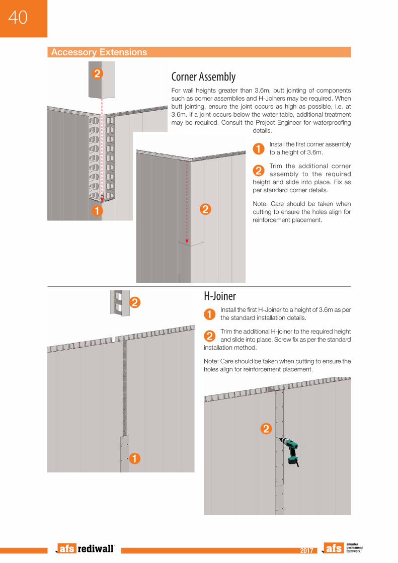
Corner AssemblyFor wall heights greater than 3.6m, butt jointing of components such as corner assemblies and H-Joiners may be required. When butt jointing, ensure the joint occurs as high as possible, i.e. at 3.6m. If a joint occurs below the water table, additional treatment may be required. Consult the Project Engineer for waterproofing
details.
➊Install the first corner assembly to a height of 3.6m.
➋Trim the additional corner assembly to the required
height and slide into place. Fix as per standard corner details.
Note: Care should be taken when cutting to ensure the holes align for reinforcement placement.
➊
➋
➋
➊
➋
➋
H-Joiner
➊Install the first H-Joiner to a height of 3.6m as per the standard installation details.
➋Trim the additional H-joiner to the required height and slide into place. Screw fix as per the standard
installation method.
Note: Care should be taken when cutting to ensure the holes align for reinforcement placement.

41
2017 2017
End Cap Installation
PVC End Cap
➊Wall ends or openings can be capped using the
rediwall® PVC end cap. Trim the end cap to the required length and slide it onto the wall end being capped.
➋Screw f ix each s ide with screws, at 150mm
centres.
WARNING: End caps are to be braced for the full height. Refer to "Bracing End Caps" on page 61.
➊
➋
Fibre Cement End CapAlternatively, 9mm thick fibre cement strip can be used in lieu of the PVC end cap. Fibre cement strips are available from AFS.
➌Cut the fibre cement to length and slide into place, behind the web at the end of the panel, as shown. Ensure the smooth
face of the fibre cement with water block treatment is installed facing the concrete fill.
WARNING: The wall end must be braced for the full height. Refer to "Bracing End Caps" on page 61.
➌➌
➌ ➌

42
2017 2017
RW256S Blade Wall
➋
➊
Blade Walls
➊When installing an RW256S blade wall, a floor track,
50x50mm angle or other is used. Fix the base to the slab at 200mm maximum centres. Place the first RW256S panel at the end of the floor track and screw fix to the track.
➋Sl ide addi t ional panels together until the blade wall
is complete. Screw fix all panels to the floor track at the panel joins. Any reinforcement bars required should be slid into place before installing the end caps.
➌Finish the end of the blade wall with the RW256S End
Cap or Fibre Cement End Cap
as shown. An RW256S Joiner is required to mate an end cap to the male end of the panel profile.
WARNING: End caps are to be braced for the full height. Refer to "Bracing End Caps" on page 61.
Note: A timber kicker can also be used for alignment and containment of the base of the blade wall.
➌
➌
➌
➊

43
2017 2017
Rediwall® Edge Form
Rediwall® Edge Form
➊Once the wall has been installed and the formwork deck is in place, use a grinder to cut out the top
edge section of the rediwall® panels.
➋Additional bracing is required along the edge form section. See edge form bracing in this manual.
➊
➊➋

44
2017 2017
Rediwall® J-Track Installation
J-TrackWhen continuing a wall to another storey, J-Tracks are used as floor track at the junction of the upper wall and suspended slab (e.g. stair shafts, lift shafts and external walls). For external walls, waterproofing details for this junction are to be determined by the Project Engineer.
➊Ensure that the suspended slab surface is free from debris and the level is checked
and corrected as required. The Project Engineer should be consulted in relation to correct starter bar placement.
➋Two beads of polyurethane sealant (e.g. Sikaflex or Bostik Seal & Flex) or as per
waterproofer's details, must be applied in accordance with the manufacturer's instructions under the rediwall® floor track (one on each side of the track) on all external walls.
➌ Rediwall® J Track is then placed in the required location and fixed to the concrete slab using a
masonry fixing gun or drill and anchor masonry fixing system. Fix with fasteners each side of the track at 500mm centres for walls up to 5m height, or at 250mm maximum centres for walls over 5m height.
➍Start the new wall as per the standard wall construction method in this manual. Ensure
any bracing is adequate for multilevel construction, refer to the Project Engineer for details.
➊
➋
➌
➌
➍

45
2017 2017
Window Openings
Sills and LintelsRediwall® PVC End Cap is used for closing off at the underside of lintels and at the sides of openings. Lintels can be built into the wall or cut out of the installed panels.
WARNING
It is imperative that all lintels and openings are provided with sufficient support to withstand the weight of concrete prior to core filling. Refer to the Bracing section on page 58 for details.
➊Install sill panels as per site plan. AFS recommends installing 2 or 3
additional panels on the side of the sill as per normal panel installation.
➋Install End Cap to the sides of the opening to the required height and
screw fix at 150mm centres each side of the wall.
➊
➋

46
2017 2017
➌Assemble the l in te l sect ion separately. Fit End Cap to the
bottom of the lintel panels and screw fix on each side of the wall at 150mm centres. Cut End Cap to allow for interlocking with adjoining panels on both ends. H-Joiners may be inserted to make up the correct distance and screw fixed at 150mm centres to both adjoining panels.
➌➌
➍
➍
➎
➏ ➏
➏
➍Slide the lintel assembly into position and screw
fix in place at each end of the lintel and on both sides of the wall at 150mm centres.
➎Trim the sill panels to create a 5º fall to the
outside face of the wall.
➏Af te r core f i l l i ng , remove end caps as
per architectural details.

47
2017 2017
Doorway & Lintel Installation
Doorway with PVC CappingRediwall® PVC end cap is used for closing off at the base of lintels and at the sides of openings. Doorways can be built into the wall or cut out of the installed panels.
It is imperative that all lintels and openings are provided with sufficient support to withstand the weight of concrete prior to core filling.
WARNING: All openings are to be braced. Refer to the Bracing section on page 58 for details.
➊Install wall panels as per s i te plan. AFS
recommends installing at least three panels on each side of the opening as per normal panel installation.
➋Install End Cap to the sides of the opening
to the required height and screw fix to both sides of the wall at 150mm centres.
➊
➋

48
2017 2017
➌Assemble the lintel section separately. Fit End Cap to the bottom of the lintel
panels and screw fix on each side of the wall at 150mm centres. Cut End Cap to allow for interlocking with adjoining panels on both ends. H-Joiners may be inserted to make up the correct distance and screw fixed at 150mm centres to both adjoining panels.
➌
➍
➍
➍Slide the lintel assembly into position and screw fix in place
on both sides of the wall and at each end of the lintel at 150mm centres.

49
2017 2017
Doorway with Steel Frame (Internal Fit Jamb)WARNING: All openings are to be braced. Refer to the Bracing section on page 58 for details.
➊Where a metal door frame is to be fitted, the
frame is slid into position with the door jamb member inside the rediwall® panel flange. Removal of some of the PVC clip profile may be required to ensure a proper fit. Screw fix at 150mm centres on both sides of the wall.
➋The next full size rediwall® panel is then placed and
engaged in the door jamb member. Screw fix at 150mm centres on both sides of the wall.
➌Lintel sections are then slid into place above the
door frame. Fix in place on both sides of the wall and at each end of the lintel using screws at
150mm centres. Removal or slitting of the panel webs may be required to ensure correct fit.
➌
➊
➋
Alternative ProceduresThe rediwall® panels either side of the doorway are fixed into position, plumbed and braced (ensuring the opening between them is accurate for the frame). The frame can then be lowered between the panels. The lintel panel is pre-assembled on-site and lowered into position, engaging into the panels on both ends and dropping down into the head of the door frame.
Retro-fitted DoorsWhere a doorway is to be retro-fitted with a door frame, the opening is constructed, capped and braced as for a window opening but without any sill panel.

50
2017 2017
Wide Radius Curved Wall Installation
Curverd walls
➊Mark inner radius of the curved wall on the slab or footing.
➋Slit the floor track on one side only (the convex side of the curve) to
allow the floor track to be bent to the shape of the curve.
➌Lower the floor track over the starter bars and place into
position to the radius required. Fix each track section to the concrete footing or slab using a masonry fixing gun or drill and anchor masonry fixing system each side of the track.
➍Begin by installing standard panels into the floor track and screw fix both sides of the
bottom of the panel to the floor track at 150mm centres.
➎Using H-Joiners as spacers, slide them in between the joins and screw fix them both
sides to each panel at 150mm centres.
Alternative ProceduresFor walls with a large radius (radius greater than 5m), the panels may be installed to follow the floor track curve without panel modification or any additional components.
After installing the curved floor track, continue the wall by erecting panels in place allowing a small direction change in each wall segment. Screw fix panels to the floor track as erection proceeds.
WARNING: Refer to the Bracing section on page 58 for details.
Additional treatment may be required for a waterpoof solution refer to the project engineers for details.
➌
➊➋
➍➍
➎
➎

51
2017 2017
Curved Wall Reinforcement Bar Installation
Installing Pre-curved BarsIf reinforcing bar is to be installed it can be pre-ordered bent to the required radius.
➊For wide radius curves – pre-bent reinforcing can be installed from one end of the wall as the panels
are being installed.
➋Install 1 or 2 more panels on the curve and feed the pre-bent reinforcing into the last installed panel.
Continue this procedure until the curve is complete.
Alternative InstallationOn long curves and tight radius curves where it not possible to insert one long length of reinforcing bar, the bar can be installed in shorter lengths as the panels are being installed. Alternatively, it may be possible to install a long length from both ends of the curve once all the panels in the curve have been installed.
At junctions with straight walls and where more than one length of reinforcing is being used in curved wall sections, it is important to ensure appropriate lapping of the bars is being achieved, in accordance with Project Engineer's specifications.
➊
➋
➋

52
2017 2017
Stairway Landing Construction
StairsWARNING: Where rediwall® panels are to be engaged with a landing or stairs, care is to be taken when creating openings in the rediwall® panel face to ensure that the web inside is not damaged causing the panels to be weakened.
➊Engagement of the wall and adjoin ing structure
can be achieved by cutting holes in the rediwall® face to install reinforcing bars. Use a hole saw as per Structural Engineer's details (100mm maximum diameter).
➋I n s e r t t h e r e q u i r e d reinforcement steel as per the
Structural Engineer's details.
NOTE: Formwork and bracing for stairs and landings is the responsibility of the site builder and engineer. Additional bracing may be required where suspended slab is tied in.
➊➋

53
2017 2017
Retention Tank Construction & Tanking
All waterproofing details are to be completed by the Project Builder and Waterproofing Contractor. When filled with concrete, rediwall® is a water resistant wall system. However specific areas requiring waterproofing details include horizontal concrete cold joints, and where water can track down along panel joints.
Any required waterproofing products must be installed strictly in accordance with the particular manufacturer's instructions.
➊Determine the line of the rediwall® panels on the slab
and install PVC floor track with centre cut out to accommodate waterstop. Mechanically fix the angle to the slab at 500 – 600mm centres.
➋I n s t a l l Wa t e r s t o p t o manufacturer's instructions,
maintaining a continuous seal. Refer to the project building designer for details on Waterstop performance and installation requirements. Ensure that the water stop remains unobstructed through the rediwall® profiles and that it is not cut by the internal webs.
➌Install the remaining rediwall® panels
as per the standard ins ta l l a t ion method. Complete the tank with the required steel reinforcing as per Engineer's details.
➍C o r e f i l l w i t h concrete following
the AFS recommended guidelines.
➎A w a t e r p r o o f tanking f inish is
required. Apply tanking (supplied by others) as per the Engineer's details.
Note: The structure must be fully braced on both faces before concrete filling. Refer to the Bracing section on page 58 for details.
➋
➊
➊
➊
➊
➋
➌➌
➎
➍
54
2017 2017
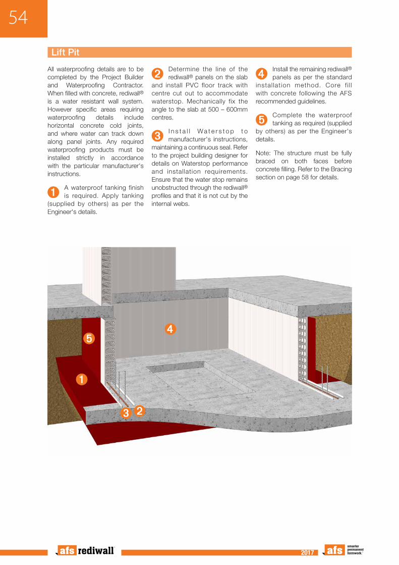
Lift Pit
All waterproofing details are to be completed by the Project Builder and Waterproofing Contractor. When filled with concrete, rediwall® is a water resistant wall system. However specific areas requiring waterproofing details include horizontal concrete cold joints, and where water can track down along panel joints. Any required waterproofing products must be installed strictly in accordance with the particular manufacturer's instructions.
➊A waterproof tanking finish is required. Apply tanking
(supplied by others) as per the Engineer's details.
➋Determine the line of the rediwall® panels on the slab
and install PVC floor track with centre cut out to accommodate waterstop. Mechanically fix the angle to the slab at 500 – 600mm centres.
➌I n s t a l l Wa t e r s t o p t o manufacturer's instructions,
maintaining a continuous seal. Refer to the project building designer for details on Waterstop performance and installation requirements. Ensure that the water stop remains unobstructed through the rediwall® profiles and that it is not cut by the internal webs.
➍Install the remaining rediwall® panels as per the standard
instal lat ion method. Core f i l l with concrete following the AFS recommended guidelines.
➎Complete the waterproof tanking as required (supplied
by others) as per the Engineer's details.
Note: The structure must be fully braced on both faces before concrete filling. Refer to the Bracing section on page 58 for details.
➊
➎➍
➋➌

55
2017 2017
Installation of Services
Services Within WallsPlacement of electrical and data services within the afs rediwall® panel must take place between installation of wall panels and prior to concrete core filling. AFS does not recommend placement of high pressure services such as water or gas lines inside the wall panels.
➊Cut a hole at the required location
for the service box.
➋I n se r t t he p re assembled conduit
and service box.
➌Screw fix the service box in place using a
plaster bracket or similar. A screw is to be placed through the conduit to ensure that it does not dislodge from the wall box.
➌
➊
➋
➋

56
2017 2017
Penetrations
Non Fire Rated Service Penetrations Penetrations for services and mechanical requirements may be cut on-site prior to core filling.
Alternatively, services penetrations may be cut/core drilled after core filling.
Refer to project specifications for details.
Rectangular Openings
➊Neatly cut out the required section from the assembled
rediwall® panels.
➋Install End Cap to the sides of the opening, and screw fix
at 150mm centres on each side of the wall.
➊
➋

57
2017 2017
Fire Rated Penetrations
Installation of a fire collar may be required in some situations.
Refer to the fire collar manufacturer's installation guide for details.
Installation of the fire collar is done after core filling.
➊Core drill the required hole from the rediwall® panels
and remove the PVC facing around the hole in accordance with the fire collar installation instructions.
➋Insert the serv ice pipe through the hole and apply a
continuous bead of fire rated sealant around the penetration directly on the exposed concrete face, refer
to manufacturer's instructions to maintain fire rating.
➌Slide the fire collar over the service pipe and fix
to the rediwall® wall as per the manufacturer's or Project Engineer's details.
➊ ➊
➋ ➋
➌ ➌

58
2017 2017
IntroductionRediwall® requires temporary bracing for lateral stability during installation and core filling. The temporary bracing must withstand wind, seismic and other construction loads that may occur during erection of the components, during placement of the concrete and until installation of the permanent floor and/or roof members that provide a lateral load resisting diaphragm.
The bracing requirements for rediwall® are to be determined based on the wall thickness, the wall height, the wall layout, the presence of permanent or temporary framing (girts, columns, roof, etc.), and the wall erection method, which is either by installing off a formwork deck or from scaffolding, or off slab or footing.
Also, the wall bracing scheme and technique depend on the specific site climatic conditions, soil and foundation conditions, material availability, location wind loads, BCA and site specific requirements.
It is highly recommended that the Project Engineer or Contractor be contacted to perform the bracing calculations and drawings based on the specific site conditions and wall layouts.
Standard bracing drawings are available for use with AFS standard braces. Alternative details can be prepared by an Engineer or Contrator.
The wind loadings are to be calculated in accordance with relevant applicable Building Codes, and with the appropriate reduction factor for temporary bracing.
The rediwall® components provide permanent formwork for both faces of a wall and include integral internal webs to hold the two faces together during concrete placement.
Rediwall® requires a horizontal whaler between braces to ensure straightness of rediwall® elements.
Bracing is also required for areas that are subject to unbalanced hydrostatic pressure during concrete placement. Typically, these areas include openings, corners, T-junctions and wall ends.
The bracing should be re-checked immediately prior to the placement of concrete to ensure that all members are properly installed and that the rediwall® components are correctly located, aligned plumbed and braced.
REDIWALL® TEMPORARY CONSTRUCTION BRACING

59
2017 2017
Bracing of Walls to 3.3m HeightAll rediwall® walls require horizontal bracing for lateral support prior to concrete pouring. This can be by attachment to a completed formwork deck or bracing struts secured to the panels and anchored to the slab.
For walls up to 3.3m height a continuous horizontal bracing member is required on one or both sides.
Site conditions such as high wind areas and work safety should be considered when bracing. Consult the Project Engineer for specific bracing requirements.
➊AFS recommends that the horizontal brace Top Hat be
attached in the top one third of the panel height or at the top of the panels. As a minimum, the bracing Top Hats should be screw fixed to each rediwall®
panel with two screws at the panel joint location.
➋The horizontal brace plate is to be connected to angled
adjustable braces that are anchored to the slab or deadmen 1100mm apart. For walls over 3.3m contact the project manager or site engineer for details on bracing requirements.
➊
➋
➋
Bracing of Walls
➊
➋

60
2017 2017
Bracing from Formwork DeckRediwall® systems less than 3.5m in height that are being installed in conjunction with a formwork deck can be braced by being fixed directly into the form ply deck.
➊Fo rmwork deck i ng should be constructed
and independently braced before erection of the rediwall® panels. Ensure deck is secure and at the appropriate height.
➋ Fix rediwall® panels to the formwork deck using
appropriate fixings at each panel.
➊
➋
61
2017 2017
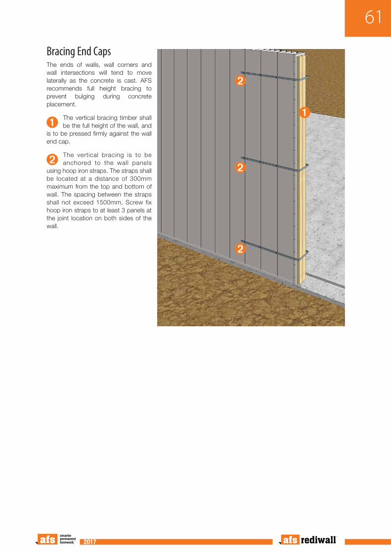
Bracing End CapsThe ends of walls, wall corners and wall intersections will tend to move laterally as the concrete is cast. AFS recommends full height bracing to prevent bulging during concrete placement.
➊The vertical bracing timber shall be the full height of the wall, and
is to be pressed firmly against the wall end cap.
➋The vertical bracing is to be anchored to the wall panels
using hoop iron straps. The straps shall be located at a distance of 300mm maximum from the top and bottom of wall. The spacing between the straps shall not exceed 1500mm. Screw fix hoop iron straps to at least 3 panels at the joint location on both sides of the wall.
➊
➋
➋
➋

62
2017 2017
Bracing of T-JunctionsWhere a T-junction is made, the main wall shall be adequately propped on the opposite side and local to the T-junction. This bracing is required to contain any lateral forces when this section of the wall is filled with concrete and to avoid dislodgement. For a short T-wall or nib, the end of this short T-wall shall also be adequately propped to stop potential bulging of T- junctions.
➊The external vertical bracing timber shall be the full height of
the wall, and is to be pressed firmly against the wall opposite the T-junction. A 300mm wide backing plate of 19mm ply should be used.
➊
➋
➋➋
The internal bracing of the T-junction is to be in accordance with the
standard bracing detail in this manual. All wall junctions must be braced.

63
2017 2017
Bracing of Rediwall® Edge Form
➊
➊
➊Contact AFS for information on edge form bracing. Alternatively contact the consulting project
engineer, contract formworker or principal building contractor for details.

64
2017 2017
Refer to construction details for sill and lintel panel installation.
Openings can be distorted during the core filling process. AFS recommends that all openings be fully braced prior to core filling.
➊Continuous timber caps are required at the top and sides
of all openings to maintain a flat surface and to prevent the face of the opening from bowing due to the vertical and horizontal concrete pressure. Caps are typically formed using conventional timber framing. The cap may be connected to the rediwall® components to prevent separation of the wall panel from the cap.
➋All t imber caps require vertical and horizontal struts
to support the head and jambs respectively, to keep the opening square, to resist the concrete pressure and weight and to maintain the correct opening dimensions.
➌The head and sill of openings more than 1.2m wide require
a whaling plate on both faces of the wall to maintain a flat plane across the opening.
➍The wha l i ng p l a t e i s connected to angled braces
(at 1100mm maximum horizontal spacings) anchored to deadmen or the floor slab, on both sides of the wall, in order to hold the opening plumb.
➊ ➊
➊
➋
➍
➍
➍
➌
➌
Bracing of Window Openings

65
2017 2017
Bracing of Doorway OpeningsRefer to construction details for sill and lintel panel installation.
Openings can be distorted during the core filling process. AFS recommends that all opening to be fully braced prior to core filling.
Bracing – Formed Doorways
➊Brace sides and head of the opening to the full width of the
wall with timber caps.
➋Install two parallel horizontal braces to the outer edges of the
caps at the top, bottom and middle of the opening.
➌Install vertical shoring as required, (adjustable props may be used).
➍A whaling plate on both faces of the wall is connected to angled
braces (at 1100mm maximum horizontal spacings) anchored to deadmen or the floor slab in order to hold the opening plumb.
Bracing – Metal Framed DoorwaysBuilt in metal door frames must be installed accurately and squared/plumbed correctly. Refer to construction details earlier in this manual.
They also require sufficient bracing to prevent distortion during concrete filling, which can be achieved by installing metal turnbuckle braces or timber bracing.
➊Brace sides of the opening to the full width of the wall with timber caps.
➋Install two parallel horizontal struts to the outer edges of the caps at the top, bottom and middle
of the opening.
➌The bottom of the metal door must also be braced to prevent the door from skewing. Run a timber
chocks along each side of the foot of the door frame and fix to the concrete slab.
➍A whaling plate on both faces of the wall is connected to angled braces (at 1100mm maximum
horizontal spacings) anchored to deadmen or the floor slab in order to hold the opening plumb.
➊
➊
➊
➊
➊
➋
➋
➋
➋
➋
➍➍
➍➍
➌
➌
➋

66
2017 2017
Bracing of Wide Radius Curved Walls
➊Ensure that all panels have been screw fixed
to the floor track, and that all H-Joiners have been screw fixed to their adjacent panels.
➋Bracing must be used on the outer radius of a
curved wall. It is recommended that at a minimum, every third wall section be braced.
➌For the internal radius of a curved wall use
the same bracing technique as for a standard wall. It is recommended that at a minimum, every third wall panel be braced.
➍Screw fix the brace to the horizontal support
and then securely fix the brace to the slab or deadman.
➊
➍
➍
➋➋
➋
➊
➌➌ ➌
➍
➍
Bracing of Tight Radius Curved Walls (not shown here)Ensure that all panels are screw fixed to the floor track and that all H-Joiners have been screw fixed to their adjacent panels.
Bracing must be used on the outer radius of a curved wall. Each infill spacer must be braced for the full height using suitable formwork timbers erected vertically against the infill spacer and braced diagonally back to the slab or deadman.
For the internal radius of a curved wall use the same bracing technique as for a standard wall. It is recommended that at a minimum, every third wall panel be braced.
Screw fix the brace to the horizontal timber support and then securely fix the brace to the slab or deadman.

67
2017 2017
CORE FILLING OF WALLSIntroductionAFS Rediwall® cannot be filled with concrete using traditional methods of compaction or vibration. The concrete mix and concrete placement technique is critical to the successful outcome of filling rediwall®.
AFS has carried out tests which achieved desired compaction and dense, homogeneous coverage of afs rediwall®.
This guide sets out the methods used by AFS to achieve compaction.
Use of this guide or an equivalent procedure to achieve compaction of rediwall® is entirely at the discretion of the contractor or installer.
The contractor or installer is responsible for achieving compaction and dense, homogeneous coverage of the concrete mix in rediwall®. AFS accepts no responsibility for achieving compaction of the concrete in afs rediwall® or core filling of walls.
Concrete Pour LimitationsWhen panel installation is complete and all appropriate bracing and checks completed, the walls can be filled with concrete.
The quantity of concrete that can be poured in a day must be assessed and determined in consideration of the following factors:
• Ease of access
• Number of passes (or lifts) that are required
• Concrete gelling time between passes
• Consideration of wet weather
For wet weather, on-site conditions should be assessed and the concrete pour either be delayed or be undertaken with caution, applying measures to suit the given conditions.
Additional Equipment Required for Concrete PourPrior to commencing a pour, ensure that a concrete vibrator (40mm diameter maximum), multiple shovels, trowels, screw guns and screws and at least one wheelbarrow are readily available.

68
2017 2017
Number of Concrete Passes/Lifts RequiredWalls up to 3 metres high can be filled in 2 passes/lifts with the first pass being to a maximum height of 1.2 – 1.5m. Walls from 3 – 6m should be filled in 3 – 4 passes with the first and second pass being to a maximum height of 1m each.
Allow at least 45minutes between passes for concrete to gel.
Higher concrete strength mixes will gel faster than low strength mix designs. These guidelines will vary according to site conditions, with the requirement of extra passes and extra gelling time in wet/cold weather. In cases of extreme weather the concrete pour should be postponed.
Concrete UsageRediwall®
PanelRW110C RW156C RW200C RW256S
Per Cubic Metre of Concrete
Square Metres of Wall Area
9.61m2 6.67m2 5.1m2 4.0m2
Per Square Metre of Wall
Area
Cubic Metres of Concrete
0.104m3 0.15m3 0.194m3 0.25m3
Concrete Mix DesignThe concrete supplier is responsible for providing a mix design that is suitable for filling rediwall®.
The concrete core fill mix must be designed with enhanced flow characteristics. Such concrete is available from Hanson Concrete and most other concrete suppliers.
AFS trials and experience have shown that a concrete mix that is designed such that segregation and blowouts are prevented whilst achieving the required level of compaction will have the following basic characteristics:
• ƒ’c = 25 to 50 MPa (to be as specified by the project structural engineer).
• Water to cement ratio of 0.55 maximum. (This may provide more cement than required for strength but the high cement content is required to enhance flow).
• 8-10mm maximum aggregate.
• Batched at 80mm slump before admixtures.
• A long line, or pumpable wall mix is normally used to fill rediwall®. The afs logicwall® mix can also be used. Block fill mix is not recommended.
Concrete Mix Design GuideStandard AFS Pump Mixes High Workability Mixes
Refer to Structural Engineer for Mix specification
Strength ƒ’c (MPa) S25 S32 S40 S50 S40 S50 S65
Target Installation Slump 140±10 140±10 140±10 140±10 170±10 170±10 170±10
Design Slump (mm) 120±30 120±30 120±30 120±30 150±30 150±30 150±30
Maximum W/C Ratio 0.7 0.6 0.45 0.4 0.45 0.4 0.35
Nominal Fine to Total Aggregate Percentage (%)
65 60 55 50 55 50 50
Maximum Aggregate Size (mm) 10 10 10 10 10 10 10
Maximum 56 Day Drying Shrinkage (um)
1000 1000 1000 1000 1000 1000 1000
Hanson Recommended Admixtures
WRPAPN20 (WR) ex Grace, ADVA-142 (HWR) ex Grace
Notes:
• Site water is allowed to be used to reach desired installation slump however, the maximum W/C ratio must not be exceeded.
• Due to local raw material availability, characteristics will vary significantly, refer to Project Engineer for further details.
• The addition of all admixtures are typically dosed at the beginning of the batch.
• Concrete mix should have a typical ‘Gel’ time of 30-60min in accordance with the Gel Test detailed in this guide.
69
2017 2017
Concrete Delivery & PlacementThe concrete must be placed using a suitable concrete pump via a 50mm delivery hose. Never fill rediwall® using a kibble.
The average pump rate for core filling afs rediwall® is 12m3 per hour. It is important to advise the concrete supply company of the required delivery turnaround time. (e.g. 1 x 5m3 load every half hour, taking approximately 30mins to empty the truck).
Admixtures including plasticiser and flyash are used to increase the target slump to 150mm maximum for standard AFS pump mixes.
Concrete 'Gel' TestThe concrete core filling of rediwall® is undertaken in passes, with concrete pours limited to 1500mm high per pass. A simple reinforcement test shall be undertaken to check that concrete in each pass has 'gelled' sufficiently before the subsequent pass (typically 45 minutes or more). The test steps are as follows:
A. After the first pass of the concrete pour, lower an N12 or N16 reinforcement bar into the rediwall® cavity until the reinforcement contacts the wet concrete.
B. Let the reinforcement bar fall under its own weight. If the reinforcement bar sinks 75 - 125mm into concrete and stops, it indicates that the concrete has 'gelled' sufficiently for the second pass of the concrete pour to commence.
C. If the reinforcement bar does not stop and continues to go down into the wet concrete, the concrete is still too wet for commencement of the second pass of the concrete pour. Allow suitable time for the concrete to 'gel'. Then, conduct the test again to check and ensure that it meets the bar sink criteria as noted in Step 'B' before proceeding to the next pass of the concrete pour.
D. Depending on wall height, the gel test shall be carried out for all subsequent passes of the concrete pour.
E. Concrete is vibrated with a 40mm diameter needle vibrator by placing the vibrator in the upper 300mm of the wall panel and vibrating the reinforcement bars if required.
Note: Over vibrating can result in bulges and/or blowouts. Avoid touching the panel faces with the vibrator. Keep vibration to a minimum.
Concrete Pour ProcedureCORNERSStart pouring the wall in the ‘Corner’. Hold the hose directly over the panels, moving back and forth over the webs and onto the horizontal reinforcement bars to slow down the concrete flow rate, till the maximum pour height of 1500mm is reached.
If pouring from one corner to the next (Lift Shaft, etc), move the hose forward to the corner and work your way back to the middle of the wall, till the maximum pour height of 1500mm is reached.
T SECTIONStart pouring the wall from the ‘T-Section’. Hold the hose directly over the panels, moving back and forth over the webs and onto the horizontal reinforcement bars to slow down the concrete flow rate, till the maximum pour height of 1500mm is reached.
If pouring from one ‘T-Section’ to the next, move the hose forward to the ‘T-Section’ and work your way back to the middle of the wall, till the maximum pour height of 1500mm is reached
END CAPS.Start pouring the wall from the ‘End Cap’. Hold the hose directly over the panels, moving back and forth over the webs and onto the horizontal reinforcement bars to slow down the concrete flow rate, till the maximum pour height of 1500mm is reached.
If pouring from one end cap to the next, move the hose forward to the endcap and work your way back to the middle of the wall, till the maximum pour height of 1500mm is reached.
COLUMNS AND BLADESStart pouring the wall from the ‘End Cap’. Hold the hose directly over the panels, moving back and forth over the webs and onto the horizontal reinforcement bars to slow down the concrete flow rate, till the maximum pour height of 1500mm is reached.
If pouring from one ‘End Cap’ to the next, move the hose forward to the ‘End Cap’ and work your way back to the middle of the wall, till the maximum pour height of 1500mm is reached
DOOR FRAMESStart pouring the wall from the ‘Door Frame’. Hold the hose directly over the panels, moving back and forth over the webs and onto the horizontal reinforcement bars to slow down the concrete flow rate, till the maximum pour height of 1500mm is reached.
If pouring from one door frame to the next, move the

70
2017 2017
hose forward to the door frame and work your way back to the middle of the wall, till the maximum pour height of 1500mm is reached.
WINDOWS AND HEADERSAt openings, such as windows or large mechanical penetrations, lower the hose under the formwork deck and ensure all sills are adequately filled. On the remaining lifts, core fill headers and lintels.
Optional use of a concrete vibrator in AFS Rediwall®Concrete is to be vibrated if needed with a 40mm diameter needle vibrator, by placing the vibrator in the upper 300mm of the wall panel and vibrate reinforcement bars for about 3 seconds at a time.
In the case of a high reo detailed option, care is to be taken when vibrating the reinforcing steel cage to ensure monolithic concrete wall.
The vibrator must not be dropped or lowered to the bottom of the panel (as done traditionally) or held against the panel faces as this may result in panel failure.
Finishing of Sills & Top of WallWhen the sills and tops of walls have been filled, they should be neatly trowel finished.
The top of the sill/wall is either:
1. Left set down slightly if a slab is to be poured over the top;
OR
2. Trowelled off smooth to 5mm fall if it is the finished top of a wall or if it is to be the bearing edge for Delta-core or Ultra-floor to sit on.
OR
3. If the top of wall is to be left exposed, an additional waterproof capping is to be added.
OR
4. Trowelled off smooth to 5º fall if it is the finished top of a window sill.
Placing of ‘L’ Bars at top of wallReinforcing ‘L’ bars may be required to be placed in the wet concrete at the top of the wall to tie the wall and future overhead floor slab together.
Reinforcing ‘L’ bars must be placed and temporarily held in-place until the concrete cures. Design, spacing and placement are the responsibility of the Project Engineer.
Start locations and pour lines
Concrete pour starting locations
First pour 1500mm max.
Second pour 1500mm max.
Third pour 1500mm max.
Concrete pour starting locations
Pour Concrete towards the middle of a wall

71
2017 2017
Concrete Clean-upDuring the pour, some concrete splatter may occur on the slab below and down the face of the afs rediwall® panels.
All concrete splatter must be cleaned off before it cures.
Team members should follow the pour, brushing all splattered concrete off the slab and walls and if necessary, wiping the walls down with a wet sponge.
Early Removal of Temporary BracingTemporary bracing is normally removed once the slab over is poured or the roof is attached. However, if due to site conditions or other circumstance, it is desirable to remove the temporary bracing earlier, approval must be obtained from the Project Engineer, especially in situations where the rediwall® is to become a retaining wall and will be back-filled against, or is to be loaded with a pre-cast slab system such as ‘Delta-core.’
Cleaning of Finished AFS Rediwall®For cleaning of finished rediwall®, use high pressure water blasting, conducted in a similar way to brick cleaning. If required, a 10% acid or lemon concentrate can be added to the cleaning mix.
Patching of holes after removal of temporary bracing can be achieved by applying colour matched filler sealant or equivalent. Once dry, remove excess with sharp chisel or blade to achieve a flat surface.

afsformwork�com�au • 1300 727 237AFS Systems Pty Ltd • 110 Airds Road, Minto NSW 2566
Disclaimer: Information presented in this document is supplied in good faith andto the best of our knowledge was accurate at the time of preparation. The provisionof this information should not be construed as a recommendation to use any of ourproducts in violation of any patent rights or in breach of any statute or regulation.Users are advised to make their own determination as to the suitability of this
information in relation to their particular purpose or specific circumstances. Sincethe information contained in this document may be applied under conditions beyondour control, no responsibility can be accepted by AFS or CSR, or its staff for anyloss or damage caused by any person acting or refraining from action as a result ofmisuse of this information.
(C) 2017 AFS Systems Pty Ltd ABN 455 760 727 88
BMS1517.1217