Embed Size (px)
Citation preview
Alternative Fuel Systems (2004) Inc.
AFS Raven Ignition System User Guide AFS Document No. 9.AO.07
Issue Date: November 7, 2008
by
Alternative Fuel Systems (2004) Inc.
Calgary, Canada

Comments, questions or reporting of any errors found regarding this document are welcome and appreciated.
Please direct them to:
Alternative Fuel Systems (2004) Inc. Unit 1, 4321 – 14th St. NE
Calgary, Alberta, Canada T2E 7A9 +1.403.262.1833 main +1.403.237.7441 fax
The Alternative Fuel Systems (2004) Inc. products are intended for use only by approved technicians trained in its theory and operation. Improper calibration or use of the system can cause unsafe conditions, premature wear or failure of engine, vehicle or electrical components, and may cause the installation to violate local laws or regulations. Know the laws in your jurisdiction - in case of a conflict, they always supersede calibrations or practices recommended in AFS engine control documentation. Disassembly, reverse compilation or unauthorized reproduction of information provided with the purchase of AFS products constitutes a copyright violation. This document is copyright ©2008 by Alternative Fuel Systems (2004) Inc. Reproduction in whole or in part of this manual is strictly prohibited, except where explicitly indicated. Some of the features and functions described in this document may be under development at the time its publication. AFS reserves the right to modify the hardware and software specifications without notice.
AFS Raven Ignition User Guide Document Number: 9.AO.07 Released: 2008-11-07
- i -
AFS Raven Ignition User Guide Document Number: 9.AO.07 Released: 2008-11-07
- ii -
TABLE OF CONTENTS
TABLE OF CONTENTS............................................................................................................................................. II
1 PREAMBLE ...................................................................................................................................................1
2 RAVEN SYSTEM COMPONENTS......................................................................................................................2 2.1 Introduction .........................................................................................................................................2 2.2 Ignition Control Module......................................................................................................................2
2.2.1 Specifications ...............................................................................................................................2 2.2.2 Installation ....................................................................................................................................3
2.3 Ignition Coils .......................................................................................................................................4 2.3.1 Specifications ...............................................................................................................................4 2.3.2 Installation ....................................................................................................................................4
2.4 Engine Speed Sensor .........................................................................................................................5 2.4.1 Specifications ...............................................................................................................................5 2.4.2 Installation ....................................................................................................................................6
2.5 Standard Timing Disk .........................................................................................................................7 2.5.1 Specifications ...............................................................................................................................7 2.5.2 Installation ....................................................................................................................................7
2.6 Wiring Harness..................................................................................................................................10 2.6.1 Specifications .............................................................................................................................10 2.6.2 Installation ..................................................................................................................................10
2.7 Manifold Absolute Pressure (MAP) Sensor ....................................................................................11 2.7.1 Specifications .............................................................................................................................11 2.7.2 Installation ..................................................................................................................................11
2.8 Engine Coolant Temperature Sensor (ECTS).................................................................................12 2.8.1 Specifications .............................................................................................................................12 2.8.2 Installation ..................................................................................................................................13
2.9 Fuel Shut-Off Solenoid Relay (Optional).........................................................................................13 2.9.1 Specifications .............................................................................................................................13 2.9.2 Installation ..................................................................................................................................14
3 SPARROWATCH SOFTWARE - RAVEN EDITION.............................................................................................15 3.1 Overview ............................................................................................................................................15
AFS Raven Ignition User Guide Document Number: 9.AO.07 Released: 2008-11-07
- iii -
3.2 System Requirements ......................................................................................................................15 3.3 Software Installation .........................................................................................................................15 3.4 Starting SparroWatch – Raven Edition ...........................................................................................16 3.5 Working with Firmware and Calibration Files ................................................................................16
3.5.1 Program Firmware Files .............................................................................................................16 3.5.2 Loading Calibration Files ............................................................................................................17 3.5.3 Reading a Calibration File from Raven.......................................................................................18 3.5.4 Saving a Calibration File to Disk.................................................................................................18
3.6 SparroWatch Viewer Screen [F2] – Raven Edition.........................................................................19 3.6.1 RPM............................................................................................................................................19 3.6.2 Ignition Timing ............................................................................................................................19 3.6.3 ECM Operating Status................................................................................................................19 3.6.4 Sync Status ................................................................................................................................19 3.6.5 Malfunction Indicator Light Status ..............................................................................................19 3.6.6 Battery Voltage ...........................................................................................................................19 3.6.7 Intake Manifold Pressure............................................................................................................19 3.6.8 Throttle Position Sensor (TPS) ...................................................................................................19 3.6.9 Engine Coolant Temperature (ECT) ...........................................................................................19 3.6.10 Vehicle Speed ..........................................................................................................................20 3.6.11 Multispark Count.......................................................................................................................20 3.6.12 Commanded Dwell ...................................................................................................................20 3.6.13 Diag Dwell Reduction Fire Order 1 to 6 ....................................................................................20 3.6.14 Reset Arm Counter ...................................................................................................................20 3.6.15 Main Loop Time........................................................................................................................20 3.6.16 Timing Disk Delta Tooth Time ..................................................................................................20 3.6.17 Timing Disk Delta Missing Tooth Time .....................................................................................20 3.6.18 Vehicle Speed Delta Pulse Time ..............................................................................................20 3.6.19 Intake Manifold Pressure Sensor Raw (Volts) ..........................................................................20 3.6.20 Throttle Position Sensor Raw (Volts)........................................................................................21 3.6.21 Engine Coolant Temperature Sensor Raw (Volts)....................................................................21
3.7 SparroWatch Editor Screen [F3] – Raven Edition..........................................................................22 3.7.1 Number of Cylinders...................................................................................................................22 3.7.2 Multispark RPM ..........................................................................................................................22 3.7.3 Analog Input A ............................................................................................................................22 3.7.4 Analog Input B ............................................................................................................................22 3.7.5 MAP Filter Coefficient .................................................................................................................22 3.7.6 TPS Idle Position ........................................................................................................................22 3.7.7 TPS Wide Open Throttle (WOT) Position ...................................................................................22 3.7.8 Vehicle Speed Input ...................................................................................................................22
AFS Raven Ignition User Guide Document Number: 9.AO.07 Released: 2008-11-07
- iv -
3.7.9 VSS Pulses per km.....................................................................................................................22 3.7.10 Output Driver A.........................................................................................................................22 3.7.11 Output Driver B.........................................................................................................................23 3.7.12 Maximum RPM Fuel Cutoff ......................................................................................................23 3.7.13 RPM Fuel Hysteresis ................................................................................................................23 3.7.14 Fuel Relay Delay ......................................................................................................................23 3.7.15 VSS Max Speed Limit...............................................................................................................23 3.7.16 VSS Max Speed Hysteresis......................................................................................................23 3.7.17 VSS Max Speed Delay .............................................................................................................23 3.7.18 Base Timing Adjustment...........................................................................................................23 3.7.19 Ignition Timing (Primary)...........................................................................................................23 3.7.20 Ignition Timing (Secondary)......................................................................................................23 3.7.21 ECT Advance ...........................................................................................................................24 3.7.22 Engine Crank Timing ................................................................................................................24 3.7.23 Ignition Dwell ............................................................................................................................24 3.7.24 System Voltage ........................................................................................................................24 3.7.25 Engine Overspeed....................................................................................................................24 3.7.26 Ignition On Overspeed..............................................................................................................24 3.7.27 Engine Overheat Temperature .................................................................................................24 3.7.28 Lock Timing Mode ....................................................................................................................25 3.7.29 Flash Diagnostic Mode .............................................................................................................25 3.7.30 Calibration Notes ......................................................................................................................25
3.8 SparroWatch Graphing/Logging Screen [F4] – Raven Edition .....................................................27 3.8.1 Graphing Data Function .............................................................................................................27 3.8.2 Logging Data Function ...............................................................................................................27
3.9 SparroWatch Setup/Cal Screen [F5] – Raven Edition....................................................................29 3.9.1 Adjustment of Ignition Timing .....................................................................................................29
4 SMART SPARK DIAGNOSTICS ......................................................................................................................30 4.1 Diagnostic Reporting........................................................................................................................30 4.2 DTC List and Blink Codes ................................................................................................................31
AFS Raven Ignition User Guide Document Number: 9.AO.07 Released: 2008-11-07
- 1 -
1 PREAMBLE
This document is an installation guide for the AFS Raven Ignition system. The document provides component specifications and installation guide as well as a guide to calibrating the ECM software. This document is only a guide and does require the user or calibrator to have a good understanding and knowledge of engine calibration and operation and be comfortable with electronics and running windows based software applications. The AFS Raven hardware and software was designed and produced by AFS Calgary Canada.
2 RAVEN SYSTEM COMPONENTS
2.1 Introduction
The AFS Raven ignition system is a distributorless spark ignition system specifically designed for gaseous fuel applications. The components that make up the system have been optimized to work together and provide a reliable, robust system that is easily integrated into retrofit and OEM applications.
The system comes complete with a 24 pin, 8 MHz Ignition Control Module, a multi-tooth engine speed pickup disk, a variable reluctance engine speed pickup sensor, and ignition coils. The components that comprise this system have been carefully integrated and optimized to operate together; therefore, no component substitutions should be made without prior AFS approval.
The vehicle’s electrical system must be in good working order; this includes the alternator and drive belts, battery, power and ground cables, as well as wiring and connectors.
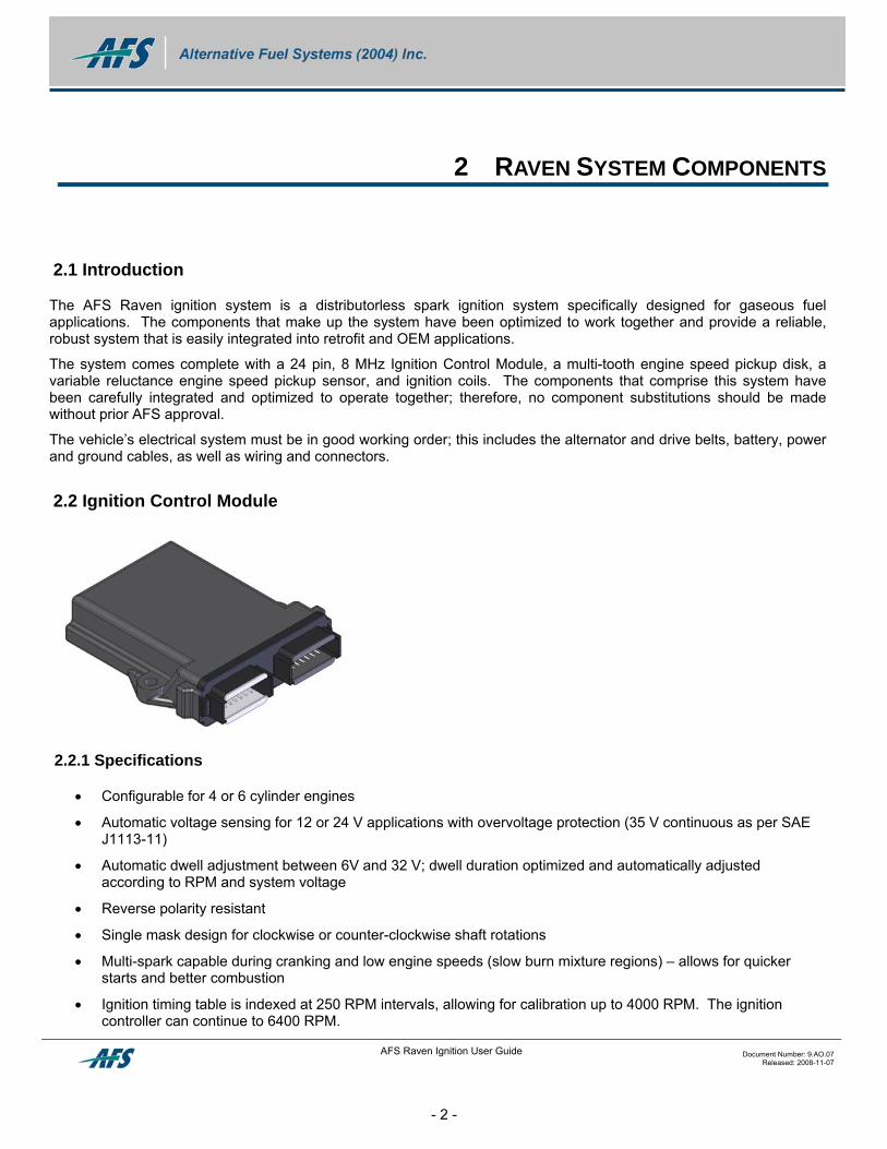
2.2 Ignition Control Module
2.2.1 Specifications
• Configurable for 4 or 6 cylinder engines
• Automatic voltage sensing for 12 or 24 V applications with overvoltage protection (35 V continuous as per SAE J1113-11)
• Automatic dwell adjustment between 6V and 32 V; dwell duration optimized and automatically adjusted according to RPM and system voltage
• Reverse polarity resistant
• Single mask design for clockwise or counter-clockwise shaft rotations
• Multi-spark capable during cranking and low engine speeds (slow burn mixture regions) – allows for quicker starts and better combustion
• Ignition timing table is indexed at 250 RPM intervals, allowing for calibration up to 4000 RPM. The ignition controller can continue to 6400 RPM.
AFS Raven Ignition User Guide Document Number: 9.AO.07 Released: 2008-11-07
- 2 -
AFS Raven Ignition User Guide Document Number: 9.AO.07 Released: 2008-11-07
- 3 -
• 2 analog inputs:
o One for throttle position sensor (TPS) or manifold absolute pressure (MAP) (optional)
o Second for engine coolant temperature or mode switch (optional) absolute pressure
• USB port interface for set up, calibration and diagnostics
• Modular design allows Raven ignition systems to be incorporated into an engine control system at a later date
• Smart spark diagnostics; full time ignition system monitoring with protective action response logic.
2.2.2 Installation
The Raven controller is designed to be robust and to tolerate typical underhood automotive environments if installed according to the instructions given here. Select its mounting location based on the following criteria:
• Install in free airflow. Cool air passing by the module will protect its components and extend its life. Remember that the hottest temperatures in automotive engine compartments are often experienced after the engine is shut off and the fan can no longer flow air through the compartment.
Caution: The temperature of the air around the controller must never exceed 121°C. Damage caused by temperatures exceeding this value will not be addressed by the manufacturer. Maximum life of the controller can be assured by keeping the ambient temperature below 85°C.
• Ensure that the connector is placed such that water will not drain directly towards the connector.
• Install well away from ignition, starter or alternator wires, coils and other high voltage or high current wires. The electrical field generated by these devices can interfere with the operation of the controller and cause intermittent faults that can be very difficult to trace.
• Install away from radios or antennas. Computer activity within the Raven controller can generate low-strength signals that can interfere with radio reception if placed too close to these components.
• Choose a location physically protected from road splash, oil, coolant and other debris.
Caution: The use of non-resistor plugs and ignition wires will cause the Raven system to malfunction. You must use only resistor-type spark plugs and ignition wires when using electronic ignition systems. A spark plug will typically have an “R” designation in its part number to identify it as a resistor style plug (i.e. NGK BP R 6 ES). Resistor ignition wires will have a small resistor built in the end of the wire. The resistor size is determined by the length of the wire (i.e. 1000 Ohms per meter of wire)
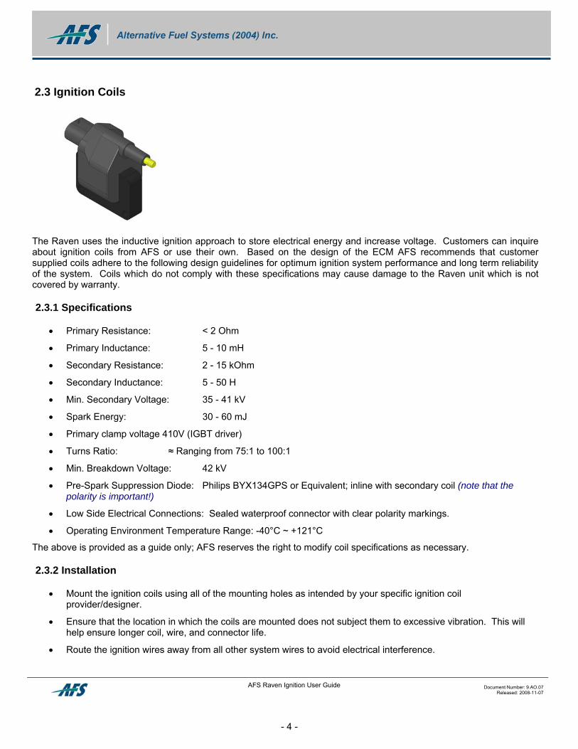
2.3 Ignition Coils
The Raven uses the inductive ignition approach to store electrical energy and increase voltage. Customers can inquire about ignition coils from AFS or use their own. Based on the design of the ECM AFS recommends that customer supplied coils adhere to the following design guidelines for optimum ignition system performance and long term reliability of the system. Coils which do not comply with these specifications may cause damage to the Raven unit which is not covered by warranty.
2.3.1 Specifications
• Primary Resistance: < 2 Ohm
• Primary Inductance: 5 - 10 mH
• Secondary Resistance: 2 - 15 kOhm
• Secondary Inductance: 5 - 50 H
• Min. Secondary Voltage: 35 - 41 kV
• Spark Energy: 30 - 60 mJ
• Primary clamp voltage 410V (IGBT driver)
• Turns Ratio: ≈ Ranging from 75:1 to 100:1
• Min. Breakdown Voltage: 42 kV
• Pre-Spark Suppression Diode: Philips BYX134GPS or Equivalent; inline with secondary coil (note that the polarity is important!)
• Low Side Electrical Connections: Sealed waterproof connector with clear polarity markings.
• Operating Environment Temperature Range: -40°C ~ +121°C
The above is provided as a guide only; AFS reserves the right to modify coil specifications as necessary.
2.3.2 Installation
• Mount the ignition coils using all of the mounting holes as intended by your specific ignition coil provider/designer.
• Ensure that the location in which the coils are mounted does not subject them to excessive vibration. This will help ensure longer coil, wire, and connector life.
• Route the ignition wires away from all other system wires to avoid electrical interference.
AFS Raven Ignition User Guide Document Number: 9.AO.07 Released: 2008-11-07
- 4 -
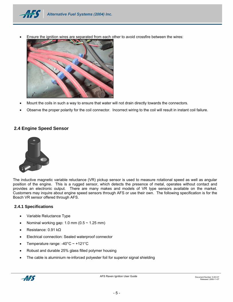
• Ensure the ignition wires are separated from each other to avoid crossfire between the wires:
• Mount the coils in such a way to ensure that water will not drain directly towards the connectors.
• Observe the proper polarity for the coil connector. Incorrect wiring to the coil will result in instant coil failure.
2.4 Engine Speed Sensor
The inductive magnetic variable reluctance (VR) pickup sensor is used to measure rotational speed as well as angular position of the engine. This is a rugged sensor, which detects the presence of metal, operates without contact and provides an electronic output. There are many makes and models of VR type sensors available on the market. Customers may inquire about engine speed sensors through AFS or use their own. The following specification is for the Bosch VR sensor offered through AFS.
2.4.1 Specifications
• Variable Reluctance Type
• Nominal working gap: 1.0 mm (0.5 ~ 1.25 mm)
• Resistance: 0.91 kΩ
• Electrical connection: Sealed waterproof connector
• Temperature range: -40°C ~ +121°C
• Robust and durable 25% glass filled polymer housing
• The cable is aluminium re-inforced polyester foil for superior signal shielding
AFS Raven Ignition User Guide Document Number: 9.AO.07 Released: 2008-11-07
- 5 -
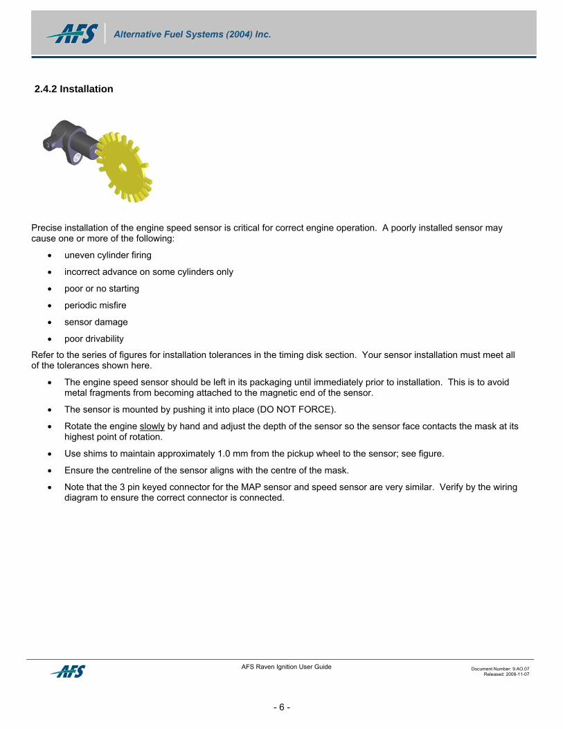
2.4.2 Installation
Precise installation of the engine speed sensor is critical for correct engine operation. A poorly installed sensor may cause one or more of the following:
• uneven cylinder firing
• incorrect advance on some cylinders only
• poor or no starting
• periodic misfire
• sensor damage
• poor drivability
Refer to the series of figures for installation tolerances in the timing disk section. Your sensor installation must meet all of the tolerances shown here.
• The engine speed sensor should be left in its packaging until immediately prior to installation. This is to avoid metal fragments from becoming attached to the magnetic end of the sensor.
• The sensor is mounted by pushing it into place (DO NOT FORCE).
• Rotate the engine slowly by hand and adjust the depth of the sensor so the sensor face contacts the mask at its highest point of rotation.
• Use shims to maintain approximately 1.0 mm from the pickup wheel to the sensor; see figure.
• Ensure the centreline of the sensor aligns with the centre of the mask.
• Note that the 3 pin keyed connector for the MAP sensor and speed sensor are very similar. Verify by the wiring diagram to ensure the correct connector is connected.
AFS Raven Ignition User Guide Document Number: 9.AO.07 Released: 2008-11-07
- 6 -
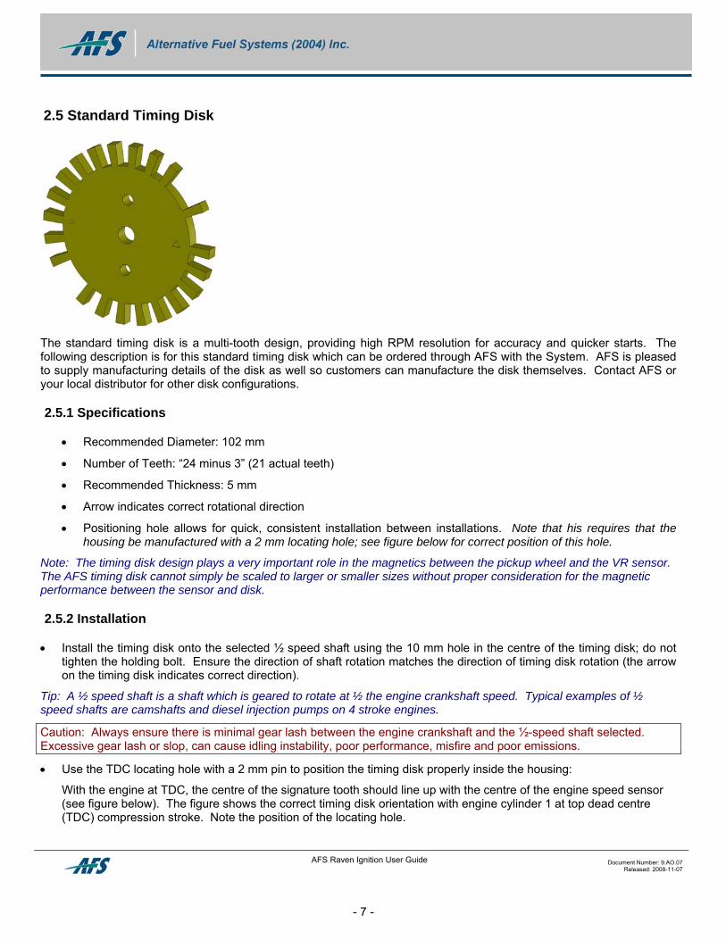
2.5 Standard Timing Disk
The standard timing disk is a multi-tooth design, providing high RPM resolution for accuracy and quicker starts. The following description is for this standard timing disk which can be ordered through AFS with the System. AFS is pleased to supply manufacturing details of the disk as well so customers can manufacture the disk themselves. Contact AFS or your local distributor for other disk configurations.
2.5.1 Specifications
• Recommended Diameter: 102 mm
• Number of Teeth: “24 minus 3” (21 actual teeth)
• Recommended Thickness: 5 mm
• Arrow indicates correct rotational direction
• Positioning hole allows for quick, consistent installation between installations. Note that his requires that the housing be manufactured with a 2 mm locating hole; see figure below for correct position of this hole.
Note: The timing disk design plays a very important role in the magnetics between the pickup wheel and the VR sensor. The AFS timing disk cannot simply be scaled to larger or smaller sizes without proper consideration for the magnetic performance between the sensor and disk.
2.5.2 Installation
• Install the timing disk onto the selected ½ speed shaft using the 10 mm hole in the centre of the timing disk; do not tighten the holding bolt. Ensure the direction of shaft rotation matches the direction of timing disk rotation (the arrow on the timing disk indicates correct direction).
Tip: A ½ speed shaft is a shaft which is geared to rotate at ½ the engine crankshaft speed. Typical examples of ½ speed shafts are camshafts and diesel injection pumps on 4 stroke engines.
Caution: Always ensure there is minimal gear lash between the engine crankshaft and the ½-speed shaft selected. Excessive gear lash or slop, can cause idling instability, poor performance, misfire and poor emissions.
• Use the TDC locating hole with a 2 mm pin to position the timing disk properly inside the housing:
With the engine at TDC, the centre of the signature tooth should line up with the centre of the engine speed sensor (see figure below). The figure shows the correct timing disk orientation with engine cylinder 1 at top dead centre (TDC) compression stroke. Note the position of the locating hole.
AFS Raven Ignition User Guide Document Number: 9.AO.07 Released: 2008-11-07
- 7 -
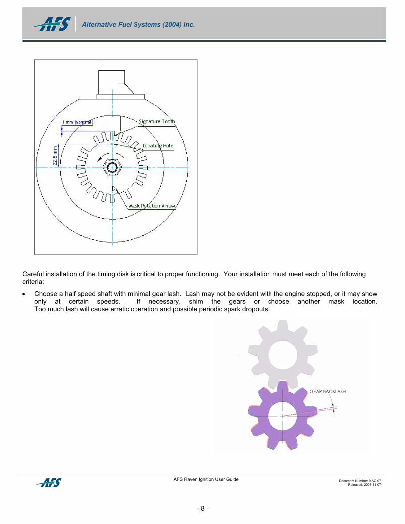
Careful installation of the timing disk is critical to proper functioning. Your installation must meet each of the following criteria:
• Choose a half speed shaft with minimal gear lash. Lash may not be evident with the engine stopped, or it may show only at certain speeds. If necessary, shim the gears or choose another mask location. Too much lash will cause erratic operation and possible periodic spark dropouts.
AFS Raven Ignition User Guide Document Number: 9.AO.07 Released: 2008-11-07
- 8 -
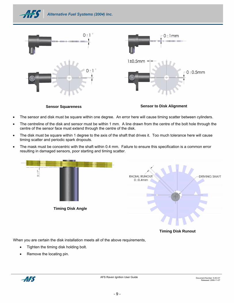
Sensor to Disk Alignment
Sensor Squareness
• The sensor and disk must be square within one degree. An error here will cause timing scatter between cylinders.
• The centreline of the disk and sensor must be within 1 mm. A line drawn from the centre of the bolt hole through the centre of the sensor face must extend through the centre of the disk.
• The disk must be square within 1 degree to the axis of the shaft that drives it. Too much tolerance here will cause timing scatter and periodic spark dropouts.
• The mask must be concentric with the shaft within 0.4 mm. Failure to ensure this specification is a common error resulting in damaged sensors, poor starting and timing scatter.
Timing Disk Runout
Timing Disk Angle
When you are certain the disk installation meets all of the above requirements,
• Tighten the timing disk holding bolt.
• Remove the locating pin.
AFS Raven Ignition User Guide Document Number: 9.AO.07 Released: 2008-11-07
- 9 -
AFS Raven Ignition User Guide Document Number: 9.AO.07 Released: 2008-11-07
- 10 -
2.6 Wiring Harness
2.6.1 Specifications
It is important to use components rated for use with automotive systems. The following list specifies the quality of the components which must be used with AFS wiring harnesses and systems:
• Wire: SAE Grade GXL 18 or 20 AWG. This wire is rated for –40 to 135°C and has good resistance to most underhood chemicals. Failing to use wire which meets these specifications could result in damage to system components due to breakdown of the wire insulation.
• Heatshrink: Must be thick-walled with adhesive liner for good strain relief and sealing; it also must withstand temperatures from –40 to 125°C without cracking or dripping, and be resistant to common underhood chemicals.
• Convoluted Tubing: Use only Nylon convoluted tubing (which can be identified by black tubing with a white stripe running down its length). Nylon is most resistant to temperature extremes (rated to 125°C) and underhood chemicals. Other materials such as polypropylene (identified by black tubing with a green stripe) are available but are susceptible to breakdown from temperature and chemical extremes.
• End Device Connectors: Where possible only use sealed connectors with positive locks to ensure reliable connections are maintained through various environments and time.
2.6.2 Installation
• Secure the wiring harness to structural components using tie straps. This will protect the harness from vibration.
• Keep the harness away from rotating components and out of any splash paths.
• Do not route the harness together with high-tension ignition leads.
• You may need to modify the length of some wires on your wire harness on some applications.
o To remove longer lengths of wire from a wire harness lead, cut the desired length of wire to be removed out of the harness and splice the wires together to bring the wire to the desired length.
o Stagger splices by about 5 cm to prevent the harness from getting too bulky.
o Shorten the convoluted tubing to match the length of wire and use an approved electrical tape to secure it on the wires.
o Coiling excess leads is a less desirable method of shortening wire harnesses, but it is acceptable provided the excess coiled leads are kept well away from ignition leads or other wires secured to an adequate support such as a nearby bracket using tie straps.
• When modifying wiring harnesses ensure that the same quality of wire, heat shrink, convoluted tubing are used as the specifications call for above to ensure the modifications are reliable.
Caution: Do not use clip-on splice connectors; these are unreliable and will cause the wire to break after only a short period of use.
2.7 Manifold Absolute Pressure (MAP) Sensor
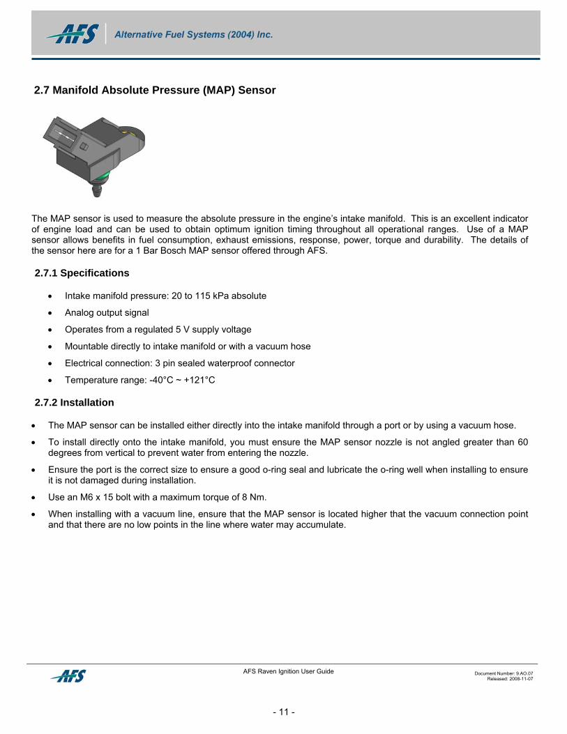
The MAP sensor is used to measure the absolute pressure in the engine’s intake manifold. This is an excellent indicator of engine load and can be used to obtain optimum ignition timing throughout all operational ranges. Use of a MAP sensor allows benefits in fuel consumption, exhaust emissions, response, power, torque and durability. The details of the sensor here are for a 1 Bar Bosch MAP sensor offered through AFS.
2.7.1 Specifications
• Intake manifold pressure: 20 to 115 kPa absolute
• Analog output signal
• Operates from a regulated 5 V supply voltage
• Mountable directly to intake manifold or with a vacuum hose
• Electrical connection: 3 pin sealed waterproof connector
• Temperature range: -40°C ~ +121°C
2.7.2 Installation
• The MAP sensor can be installed either directly into the intake manifold through a port or by using a vacuum hose.
• To install directly onto the intake manifold, you must ensure the MAP sensor nozzle is not angled greater than 60 degrees from vertical to prevent water from entering the nozzle.
• Ensure the port is the correct size to ensure a good o-ring seal and lubricate the o-ring well when installing to ensure it is not damaged during installation.
• Use an M6 x 15 bolt with a maximum torque of 8 Nm.
• When installing with a vacuum line, ensure that the MAP sensor is located higher that the vacuum connection point and that there are no low points in the line where water may accumulate.
AFS Raven Ignition User Guide Document Number: 9.AO.07 Released: 2008-11-07
- 11 -
2.8 Engine Coolant Temperature Sensor (ECTS)
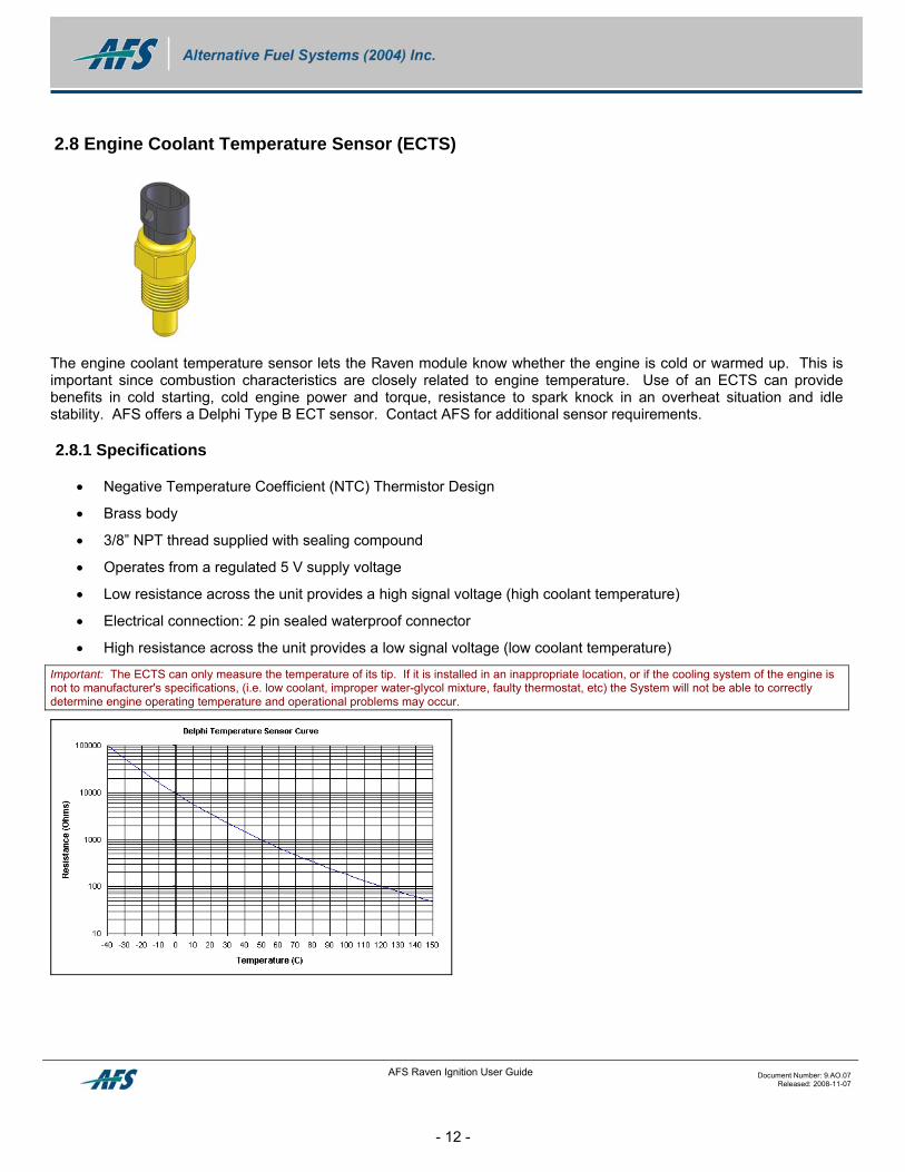
The engine coolant temperature sensor lets the Raven module know whether the engine is cold or warmed up. This is important since combustion characteristics are closely related to engine temperature. Use of an ECTS can provide benefits in cold starting, cold engine power and torque, resistance to spark knock in an overheat situation and idle stability. AFS offers a Delphi Type B ECT sensor. Contact AFS for additional sensor requirements.
2.8.1 Specifications
• Negative Temperature Coefficient (NTC) Thermistor Design
• Brass body
• 3/8” NPT thread supplied with sealing compound
• Operates from a regulated 5 V supply voltage
• Low resistance across the unit provides a high signal voltage (high coolant temperature)
• Electrical connection: 2 pin sealed waterproof connector
• High resistance across the unit provides a low signal voltage (low coolant temperature)
Important: The ECTS can only measure the temperature of its tip. If it is installed in an inappropriate location, or if the cooling system of the engine is not to manufacturer's specifications, (i.e. low coolant, improper water-glycol mixture, faulty thermostat, etc) the System will not be able to correctly determine engine operating temperature and operational problems may occur.
AFS Raven Ignition User Guide Document Number: 9.AO.07 Released: 2008-11-07
- 12 -
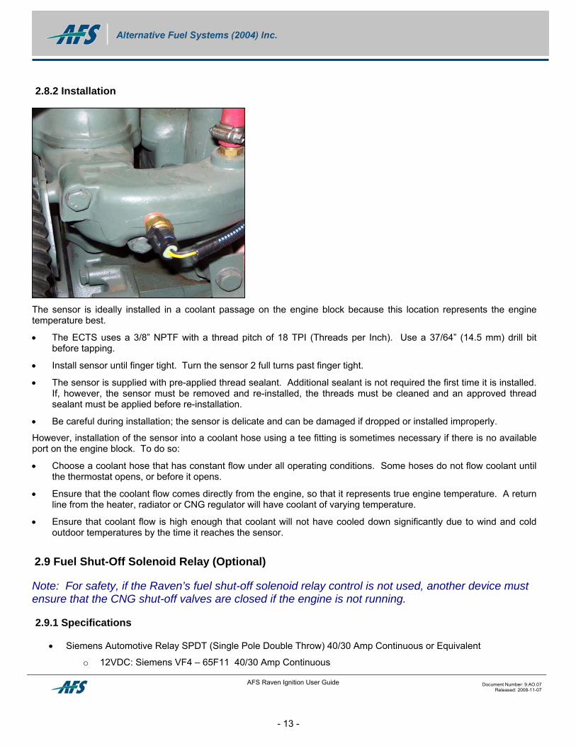
2.8.2 Installation
The sensor is ideally installed in a coolant passage on the engine block because this location represents the engine temperature best.
• The ECTS uses a 3/8” NPTF with a thread pitch of 18 TPI (Threads per Inch). Use a 37/64” (14.5 mm) drill bit before tapping.
• Install sensor until finger tight. Turn the sensor 2 full turns past finger tight.
• The sensor is supplied with pre-applied thread sealant. Additional sealant is not required the first time it is installed. If, however, the sensor must be removed and re-installed, the threads must be cleaned and an approved thread sealant must be applied before re-installation.
• Be careful during installation; the sensor is delicate and can be damaged if dropped or installed improperly.
However, installation of the sensor into a coolant hose using a tee fitting is sometimes necessary if there is no available port on the engine block. To do so:
• Choose a coolant hose that has constant flow under all operating conditions. Some hoses do not flow coolant until the thermostat opens, or before it opens.
• Ensure that the coolant flow comes directly from the engine, so that it represents true engine temperature. A return line from the heater, radiator or CNG regulator will have coolant of varying temperature.
• Ensure that coolant flow is high enough that coolant will not have cooled down significantly due to wind and cold outdoor temperatures by the time it reaches the sensor.
2.9 Fuel Shut-Off Solenoid Relay (Optional)
Note: For safety, if the Raven’s fuel shut-off solenoid relay control is not used, another device must ensure that the CNG shut-off valves are closed if the engine is not running.
2.9.1 Specifications
• Siemens Automotive Relay SPDT (Single Pole Double Throw) 40/30 Amp Continuous or Equivalent
o 12VDC: Siemens VF4 – 65F11 40/30 Amp Continuous
AFS Raven Ignition User Guide Document Number: 9.AO.07 Released: 2008-11-07
- 13 -
o 24VDC: Siemens VF4 – 65H11 40/30 Amp Continuous
2.9.2 Installation
• Please see the Raven ignition system wiring diagram for wiring installation details.
Caution: Always observe that the voltage rating of the relay is correct for your application.
• Always mount relays with the terminals pointing down to prevent water damage to the contacts.
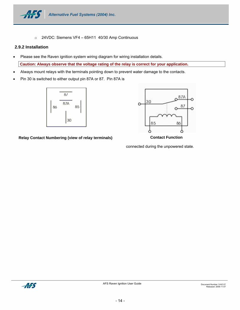
• Pin 30 is switched to either output pin 87A or 87. Pin 87A is
connected during the unpowered state.
Relay Contact Numbering (view of relay terminals) Contact Function
AFS Raven Ignition User Guide Document Number: 9.AO.07 Released: 2008-11-07
- 14 -
3 SPARROWATCH SOFTWARE - RAVEN EDITION
3.1 Overview
AFS has designed a user-friendly PC software interface for use with the Raven controller. The Raven Edition of SparroWatch allows the user to load calibration and firmware files, monitor system variables, troubleshoot problems, log data and view operational data.
3.2 System Requirements
Before installing the Software, ensure the computer you are using meets the following minimum requirements:
• Pentium (or equivalent) 120 MHz
• 128 MB RAM
• 1 free USB Port
• CD-ROM drive
• Minimum 800 x 600 screen resolution
• Microsoft Windows XP or 2000 – SparroWatch does not support Microsoft Vista or Windows 98 or earlier.
3.3 Software Installation
1. Insert the CD into your computer’s CD-ROM drive and close the drive.
2. The program should automatically load once the CD is in the drive (if autorun is enabled on your computer)
3. Follow the on-screen instructions.
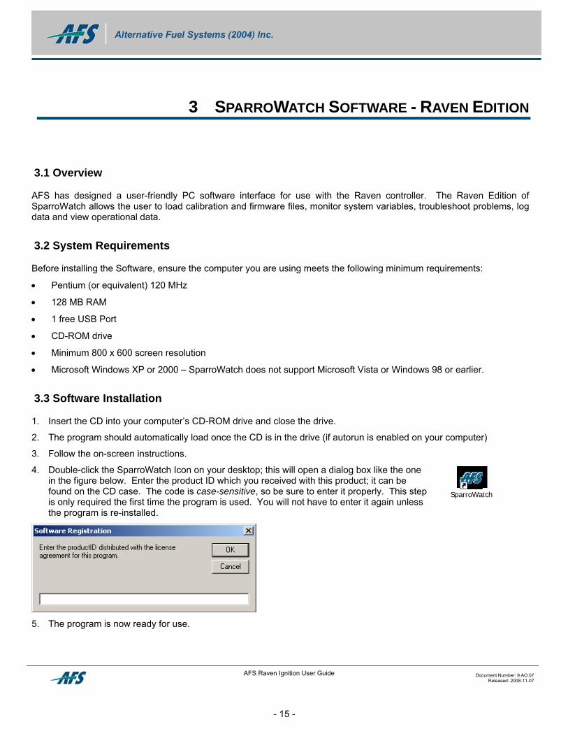
4. Double-click the SparroWatch Icon on your desktop; this will open a dialog box like the one in the figure below. Enter the product ID which you received with this product; it can be found on the CD case. The code is case-sensitive, so be sure to enter it properly. This step is only required the first time the program is used. You will not have to enter it again unless the program is re-installed.
SparroWatch
5. The program is now ready for use.
AFS Raven Ignition User Guide Document Number: 9.AO.07 Released: 2008-11-07
- 15 -
3.4 Starting SparroWatch – Raven Edition
With the Raven power off, connect the AFS Data Link to the computer USB port and the Raven’s data link connector.
• Double-click on the SparroWatch icon that should now be on your computer’s desktop (if the program is not already running). When the program opens, the first screen shows the AFS logo and program information; this screen will disappear after a moment. Once the opening screen disappears, the application window will appear on your screen.
• A light bulb appears in the lower right hand corner of the application window (see icon at right). It will appear to be unlit. After applying power to the Raven system, click on it to enable communication with the Sparrow.
• When communication is enabled, it will appear to light up (see icon at right).
If the computer cannot find a powered-up Raven ECM, it will not light up and a window will appear indicating that a PC-Link was not established. If a link could not be established, check the following:
• Ensure that a Datalink cable is connected between the vehicle and the computer.
• The vehicle ignition key must be in the “ON” position.
• Check for blown fuses or an interruption in the power supply to the ECM.
• There must be no other devices interfering with the communication port settings on your computer.
• Check the “COM port” settings in SparroWatch (found under Options>Preferences). Ensure the “Use USB Datalink” tick box is checked off. Use the “Detect and Auto-Configure USB Datalink” function button.
• Try re-booting with AC power connected.
• If you still have difficulties in establishing communication between the PC and ECM consult the USB Datalink user guide for more details.
3.5 Working with Firmware and Calibration Files
3.5.1 Program Firmware Files
Caution: Before programming firmware or calibration files, ensure that you have approved files from AFS Technical Support. Not all firmware or calibration files are compatible with each other or with the hardware configuration you are using. Using improper files may damage electronic components or cause operational and safety problems. If in doubt, e-mail AFS Technical Support at [email protected].
NOTE: This is a sequential procedure, do not skip any steps! Close all other programs, disable any power saving modes, and ensure your laptop PC is plugged in or the battery is fully charged. Interrupting the programming sequence may corrupt the flash image being programmed in to the ECM that if operated could cause poor engine operation and potentially damage system components.
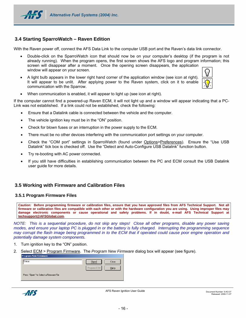
1. Turn ignition key to the “ON” position.
2. Select ECM > Program Firmware. The Program New Firmware dialog box will appear (see figure).
AFS Raven Ignition User Guide Document Number: 9.AO.07 Released: 2008-11-07
- 16 -
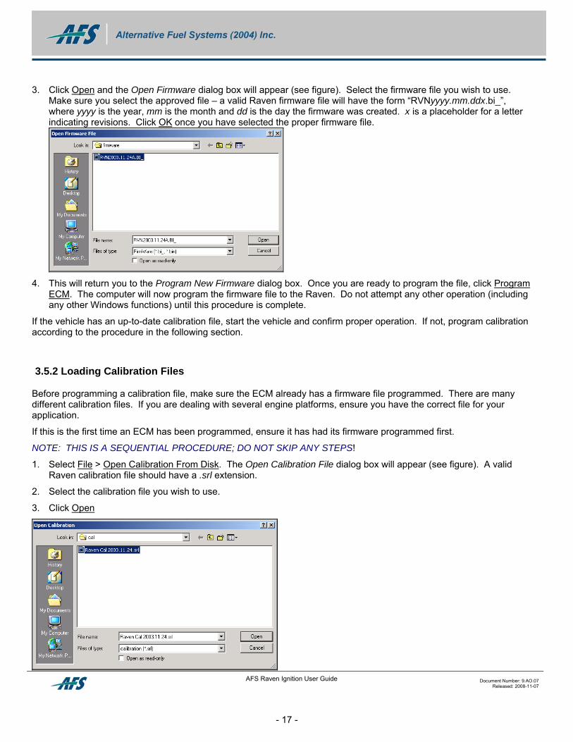
3. Click Open and the Open Firmware dialog box will appear (see figure). Select the firmware file you wish to use. Make sure you select the approved file – a valid Raven firmware file will have the form “RVNyyyy.mm.ddx.bi_”, where yyyy is the year, mm is the month and dd is the day the firmware was created. x is a placeholder for a letter indicating revisions. Click OK once you have selected the proper firmware file.
4. This will return you to the Program New Firmware dialog box. Once you are ready to program the file, click Program
ECM. The computer will now program the firmware file to the Raven. Do not attempt any other operation (including any other Windows functions) until this procedure is complete.
If the vehicle has an up-to-date calibration file, start the vehicle and confirm proper operation. If not, program calibration according to the procedure in the following section.
3.5.2 Loading Calibration Files
Before programming a calibration file, make sure the ECM already has a firmware file programmed. There are many different calibration files. If you are dealing with several engine platforms, ensure you have the correct file for your application.
If this is the first time an ECM has been programmed, ensure it has had its firmware programmed first.
NOTE: THIS IS A SEQUENTIAL PROCEDURE; DO NOT SKIP ANY STEPS!
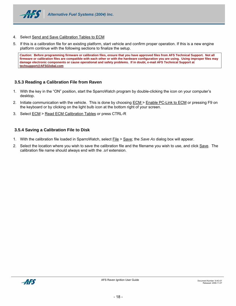
1. Select File > Open Calibration From Disk. The Open Calibration File dialog box will appear (see figure). A valid Raven calibration file should have a .srl extension.
2. Select the calibration file you wish to use.
3. Click Open
AFS Raven Ignition User Guide Document Number: 9.AO.07 Released: 2008-11-07
- 17 -
AFS Raven Ignition User Guide Document Number: 9.AO.07 Released: 2008-11-07
- 18 -
4. Select Send and Save Calibration Tables to ECM
5. If this is a calibration file for an existing platform, start vehicle and confirm proper operation. If this is a new engine platform continue with the following sections to finalize the setup.
Caution: Before programming firmware or calibration files, ensure that you have approved files from AFS Technical Support. Not all firmware or calibration files are compatible with each other or with the hardware configuration you are using. Using improper files may damage electronic components or cause operational and safety problems. If in doubt, e-mail AFS Technical Support at [email protected]
3.5.3 Reading a Calibration File from Raven
1. With the key in the “ON” position, start the SparroWatch program by double-clicking the icon on your computer’s desktop.
2. Initiate communication with the vehicle. This is done by choosing ECM > Enable PC-Link to ECM or pressing F9 on the keyboard or by clicking on the light bulb icon at the bottom right of your screen.
3. Select ECM > Read ECM Calibration Tables or press CTRL-R
3.5.4 Saving a Calibration File to Disk
1. With the calibration file loaded in SparroWatch, select File > Save; the Save As dialog box will appear.
2. Select the location where you wish to save the calibration file and the filename you wish to use, and click Save. The calibration file name should always end with the .srl extension.
AFS Raven Ignition User Guide Document Number: 9.AO.07 Released: 2008-11-07
- 19 -
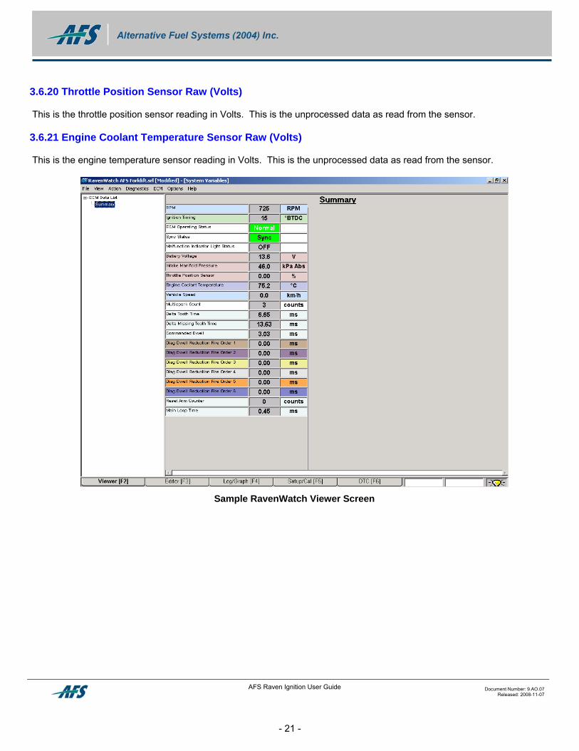
3.6 SparroWatch Viewer Screen [F2] – Raven Edition
3.6.1 RPM
This is the engine speed as read by the engine speed sensor. Note there is a resolution of 25 RPM.
3.6.2 Ignition Timing
This is the ignition timing that the Raven module is commanding.
3.6.3 ECM Operating Status
This flag will indicate 1 of 4 possible operating modes:
Crank – when engine speed is below 500 RPM
Stopped – When key is in the ON position but there is no signal from the engine speed sensor
Normal – Engine is running with an RPM between 500 and the engine speed limit (or 6375 RPM, whichever is lower)
Deceleration Fuel Cut-Off (DFCO) – when the RPM overspeed limit for fuel solenoid is enabled
3.6.4 Sync Status
This flag will indicate 1 of 2 possible flags:
Sync – means the Raven module is receiving a consistent strong signal from the timing disk and is keeping track of its position.
No Sync – means the signal is not consistent enough for the Raven to be confident of its position on the timing disk.
3.6.5 Malfunction Indicator Light Status
This is the malfunction flag and shows the status of the dashboard Malfunction Indicator Light.
3.6.6 Battery Voltage
This is the system voltage that is being supplied to the Raven module.
3.6.7 Intake Manifold Pressure
This is the absolute pressure in the intake manifold as measured by the MAP sensor. This value is zero if a TPS is used.
3.6.8 Throttle Position Sensor (TPS)
This is the throttle position in %. This value will range from 0-100%. A value of 0 will remain if a MAP sensor is used.
3.6.9 Engine Coolant Temperature (ECT)
This is the engine temperature as measured by the engine coolant temperature sensor. If no ECT is installed, the cell will substitute a value of 75.2 degrees C.
AFS Raven Ignition User Guide Document Number: 9.AO.07 Released: 2008-11-07
- 20 -
3.6.10 Vehicle Speed
This is the vehicle speed as determined by a vehicle speed sensor. The cell will display zero if no sensor is installed.
3.6.11 Multispark Count
This flag will indicate a value between 0 and 5. This value is the number of EXTRA lower-energy sparks in addition to the main spark. For example: A value of 0 indicates no extra sparks, either due to the RPM being too high for multiple sparks, or the RPM is higher than the calibrated RPM limit for multispark to be enabled.
3.6.12 Commanded Dwell
This is the dwell time for the ignition coils. The commanded dwell is the amount of time to charge the coil. This value will change with engine speed and system voltage. The dwell is non-calibratable and has been fine-tuned only for the ignition coils supplied with your system.
3.6.13 Diag Dwell Reduction Fire Order 1 to 6
If the Raven detects a disconnected wire or a condition that could damage the controller or a coil, it will reduce current to the affected coil. This is the reduction in dwell time for any particular coil from the commanded dwell time. For example: for a Commanded Dwell of 3 ms and a Diag Dwell Reduction of 0.5 ms the actual dwell time will be 2.5 ms for that coil only.
3.6.14 Reset Arm Counter
During normal Raven module operation, this value will read zero. In the event the Raven module needs to reset (due to noise, intermittent connections or other reasons), a value of 100 will be displayed and this decrements with time. It will take 5 seconds of operation without the Raven module being reset for this to go down to zero. This is helpful in finding intermittent glitches or power losses.
3.6.15 Main Loop Time
This is the amount of time it takes the Raven to complete 1 set of calculations. This will vary from application to application with the number of sensors etc. This is helpful for AFS Technical Support diagnosis and troubleshooting.
3.6.16 Timing Disk Delta Tooth Time
This is the time between edges of the timing disk measured at that engine speed.
3.6.17 Timing Disk Delta Missing Tooth Time
This is the actual time it takes between teeth edges for the missing tooth section of the timing disk.
3.6.18 Vehicle Speed Delta Pulse Time
This is the time between pulses of the vehicle speed sensor if one is installed. If no sensor is hooked up this will display as zero.
3.6.19 Intake Manifold Pressure Sensor Raw (Volts)
This is the absolute pressure in the intake manifold as measured by the MAP sensor. This is the unprocessed data as read from the sensor in Volts.
3.6.20 Throttle Position Sensor Raw (Volts)
This is the throttle position sensor reading in Volts. This is the unprocessed data as read from the sensor.
3.6.21 Engine Coolant Temperature Sensor Raw (Volts)
This is the engine temperature sensor reading in Volts. This is the unprocessed data as read from the sensor.
Sample RavenWatch Viewer Screen
AFS Raven Ignition User Guide Document Number: 9.AO.07 Released: 2008-11-07
- 21 -
AFS Raven Ignition User Guide Document Number: 9.AO.07 Released: 2008-11-07
- 22 -
3.7 SparroWatch Editor Screen [F3] – Raven Edition
3.7.1 Number of Cylinders
Use this table to select 4 or 6 cylinder engine configuration. If a value of anything other than 4 or 6 is entered, Raven will default to 6.
3.7.2 Multispark RPM
Above this RPM value, the multispark function will be disabled. Below this value, the Raven will give additional lower-energy sparks where possible to increase combustion robustness. The number of extra sparks is automatically determined by the Raven controller.
3.7.3 Analog Input A
Select the appropriate load input: MAP, TPS or none. Ensure you choose the correct part as they are not interchangeable.
3.7.4 Analog Input B
Tells the Raven controller whether you are using an engine coolant temperature sensor.
3.7.5 MAP Filter Coefficient
This is a value between 0 and 1 to condition the signal from the MAP sensor. A value of 0 provides no filtering and a value of 1 provides maximum filtering. More filtering stabilizes the MAP sensor, but slows its response.
3.7.6 TPS Idle Position
This is the value in % that the TPS reads when the engine is at idle. The Raven module will use this value for scaling purposes to determine load on the engine when a TPS is used instead of a MAP sensor.
3.7.7 TPS Wide Open Throttle (WOT) Position
This is the value in % that the TPS reads when the throttle is wide open. This is used in conjunction with the Idle position setting to scale the TPS.
3.7.8 Vehicle Speed Input
This allows you to select this input for either a vehicle speed input or a Secondary Timing Table switch input.
3.7.9 VSS Pulses per km
Enter the number of pulses per kilometer that is provided from the vehicle speed sensor. This is used to calculate vehicle speed.
3.7.10 Output Driver A
Select to control a fuel control relay. You must use a relay that draws 0.5 A or less.
AFS Raven Ignition User Guide Document Number: 9.AO.07 Released: 2008-11-07
- 23 -
3.7.11 Output Driver B
This output can be configured to be used for a Malfunction Indicator Light or an engine speed output signal for a fuel controller or a mechanical tachometer. The maximum current is 0.5 A.
3.7.12 Maximum RPM Fuel Cutoff
This is the RPM above which the fuel shut-off relay will be opened to stop the fuel flow to prevent engine overspeed.
3.7.13 RPM Fuel Hysteresis
This is the amount the RPM must drop below the Maximum Fuel RPM Cutoff in order for the fuel relay contacts to close and re-activate fuel delivery. Proper use of this variable can make the engine overspeed cutoff function more smoothly.
3.7.14 Fuel Relay Delay
This is the number of teeth on the timing disk that the Raven module must receive on startup before the fuel will be turned on. For example: A value of 0 would mean the fuel will be turned on at the first tooth. The maximum allowed is 255 teeth. This is used to ensure the fuel relay is not accidentally turned on due to electrical noise.
3.7.15 VSS Max Speed Limit
This is the maximum vehicle speed allowed. This requires the use of a vehicle speed sensor and fuel shut-off solenoid valve.
3.7.16 VSS Max Speed Hysteresis
This is the amount the vehicle speed must drop below the VSS Max Speed Limit in order for the fuel relay contacts to close and re-activate fuel delivery. Proper use of this variable can make the vehicle speed control function more smoothly.
3.7.17 VSS Max Speed Delay
This is the number of seconds that the Raven module must wait after dropping below the VSS Max Speed Limit in order for the fuel to be turned on.
3.7.18 Base Timing Adjustment
This value is used to offset ignition timing in the calibration file. This should be used only if a fleet of vehicles requires the same correction to its timing disk installation. Normally, this value should remain at zero.
3.7.19 Ignition Timing (Primary)
This is the main ignition timing table. The top of the table represents load (MAP or TPS position) and the Y axis represents engine speed in RPM. See figure for an example of an ignition timing table. Note: If you are not using a MAP sensor or TPS, all rows must be filled with the same RPM-dependent values.
3.7.20 Ignition Timing (Secondary)
This is the secondary ignition timing table. This table is ONLY used when the Vehicle Speed Input pin is configured as a "secondary timing table selection switch". If the switch is in the open position, the ECM will use the Primary Ignition Timing table by default. If the switch connects this pin to ground, the ECM will use this ignition timing table. An
AFS Raven Ignition User Guide Document Number: 9.AO.07 Released: 2008-11-07
- 24 -
application for this function is a "poor quality fuel" switch, where the operator of the vehicle needs to select a different timing table depending on the source and quality of fuel. Note: For this function to work, the ECM must be AFS part number 20-01699-01
The top of the table represents load (MAP or TPS position) and the Y axis represents engine speed in RPM. Note: If you are not using a MAP sensor or TPS, all rows must be filled with the same RPM-dependent values.
3.7.21 ECT Advance
This is an adjustment to the main timing which can be used when an ECTS is used with the Raven ignition system. As engines warm up, they require less timing advance due to faster combustion. This table adds or subtracts the ignition timing from the main ignition timing table. This can be set to zero to disable this function.
3.7.22 Engine Crank Timing
Allows specific ignition timing for use when starting the engine.
3.7.23 Ignition Dwell
Ignition dwell is the "charge" time of the ignition coil prior to a spark event. The longer the dwell, the higher the current level builds in the ignition coil. Typically, the target current level of the coil should peak between 5 and 8 Amps. Dwell should be longer at lower voltage levels, and shorter at higher voltage levels. This relationship may not be linear. It is best to use an oscilloscope and current probe to target the ideal current level versus dwell time and battery voltage. Typically, dwell is calibrated to 3 milliseconds at 12 Volts. Consult the ignition coil manufacturer's instructions for more details.
Note: It is a common misconception that more dwell results in better engine combustion. Calibrating dwell too high can cause pre-mature spark plug wear, damaged ignition coils or permanent damage to the controller. Caution is advised when calibrating this table.
3.7.24 System Voltage
Though the Raven automatically adjusts for system voltage, setting this value allows the diagnostic functions to identify whether vehicle voltage is exceeding the limits for proper operation.
3.7.25 Engine Overspeed
For diagnostic purposes only, this allows the Raven diagnostic function to detect that the engine has exceeded a safe operating speed. This can be used by fleet managers to detect damaging operating conditions.
3.7.26 Ignition On Overspeed
This option is used to disable ignition if the engine speed exceeds the RPM set in the "Engine Overspeed" calibration cell. This is an extreme measure used to protect the engine if engine speed exceeds critical levels.
WARNING - Do not use this option for any other purpose than extreme engine speed condition protection. Disabling the ignition can in itself cause backfires and engine and catalyst damage. It should be used only as a last resort.
To set engine protection by disabling ignition, select the "Disable ignition during engine overspeed" option.
3.7.27 Engine Overheat Temperature
Enter the value at which the MIL will be illuminated to alert the driver of an overheat condition.
AFS Raven Ignition User Guide Document Number: 9.AO.07 Released: 2008-11-07
- 25 -
3.7.28 Lock Timing Mode
This is the timing the Raven will lock in when using the Diagnostic Timing Jumper. It will usually be 10 degrees BTDC.
3.7.29 Flash Diagnostic Mode
This is a pulldown to select how the Raven Module handles diagnostic codes with respect to the Diagnostic Timing Jumper.
Disable Diagnostic Code Flashing Function: This disables DTCs to be flashed from the Diagnostic Timing Jumper tool.
Enable Diagnostic Code Flashing Function: This enables DTCs to be flashed from the Diagnostic Timing Jumper tool.
Enable Diagnostic Code Flashing and Clear Diagnostic Capability: This enables DTCs to be flashed from the Diagnostic Timing Jumper tool as well as clear the codes if the tool is removed at the strobe mode of the light.
3.7.30 Calibration Notes
The user can use this table to add important notes regarding calibration, vehicle type, date of installation, installer I.D. and anything else that may be of use. There is a limit of 2048 characters. The engine cannot be running when sending this table to the Raven controller.
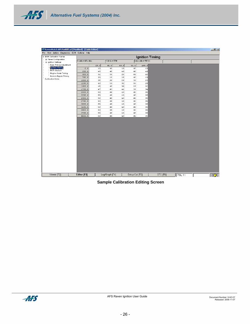
Sample Calibration Editing Screen
AFS Raven Ignition User Guide Document Number: 9.AO.07 Released: 2008-11-07
- 26 -
3.8 SparroWatch Graphing/Logging Screen [F4] – Raven Edition
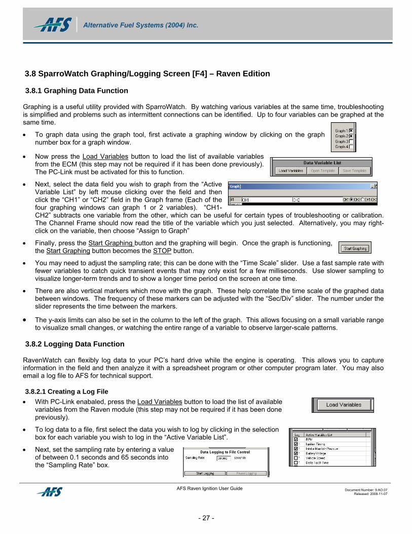
3.8.1 Graphing Data Function
Graphing is a useful utility provided with SparroWatch. By watching various variables at the same time, troubleshooting is simplified and problems such as intermittent connections can be identified. Up to four variables can be graphed at the same time.
• To graph data using the graph tool, first activate a graphing window by clicking on the graph number box for a graph window.
• Now press the Load Variables button to load the list of available variables from the ECM (this step may not be required if it has been done previously). The PC-Link must be activated for this to function.
• Next, select the data field you wish to graph from the “Active Variable List” by left mouse clicking over the field and then click the “CH1” or “CH2” field in the Graph frame (Each of the four graphing windows can graph 1 or 2 variables). “CH1-CH2” subtracts one variable from the other, which can be useful for certain types of troubleshooting or calibration. The Channel Frame should now read the title of the variable which you just selected. Alternatively, you may right-click on the variable, then choose “Assign to Graph”
• Finally, press the Start Graphing button and the graphing will begin. Once the graph is functioning, the Start Graphing button becomes the STOP button.
• You may need to adjust the sampling rate; this can be done with the “Time Scale” slider. Use a fast sample rate with fewer variables to catch quick transient events that may only exist for a few milliseconds. Use slower sampling to visualize longer-term trends and to show a longer time period on the screen at one time.
• There are also vertical markers which move with the graph. These help correlate the time scale of the graphed data between windows. The frequency of these markers can be adjusted with the “Sec/Div” slider. The number under the slider represents the time between the markers.
• The y-axis limits can also be set in the column to the left of the graph. This allows focusing on a small variable range to visualize small changes, or watching the entire range of a variable to observe larger-scale patterns.
3.8.2 Logging Data Function
RavenWatch can flexibly log data to your PC’s hard drive while the engine is operating. This allows you to capture information in the field and then analyze it with a spreadsheet program or other computer program later. You may also email a log file to AFS for technical support.
3.8.2.1 Creating a Log File • With PC-Link enabaled, press the Load Variables button to load the list of available
variables from the Raven module (this step may not be required if it has been done previously).
• To log data to a file, first select the data you wish to log by clicking in the selection box for each variable you wish to log in the “Active Variable List”.
• Next, set the sampling rate by entering a value of between 0.1 seconds and 65 seconds into the “Sampling Rate” box.
AFS Raven Ignition User Guide Document Number: 9.AO.07 Released: 2008-11-07
- 27 -
Note: Adjust the rate based on what you are trying to log. The more frequent the sampling rate and the more variables the program has to log, the larger the file will be. Also, if you have selected a large number of variables or your computer is a bit slow, the program may not be able to keep up to your sampling rate.
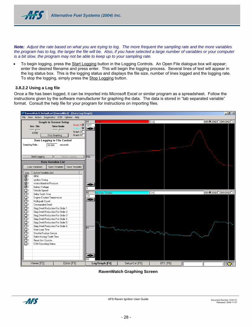
• To begin logging, press the Start Logging button in the Logging Controls. An Open File dialogue box will appear; enter the desired filename and press enter. This will begin the logging process. Several lines of text will appear in the log status box. This is the logging status and displays the file size, number of lines logged and the logging rate. To stop the logging, simply press the Stop Logging button.
3.8.2.2 Using a Log file Once a file has been logged, it can be imported into Microsoft Excel or similar program as a spreadsheet. Follow the instructions given by the software manufacturer for graphing the data. The data is stored in “tab separated variable” format. Consult the help file for your program for instructions on importing files.
RavenWatch Graphing Screen
AFS Raven Ignition User Guide Document Number: 9.AO.07 Released: 2008-11-07
- 28 -
AFS Raven Ignition User Guide Document Number: 9.AO.07 Released: 2008-11-07
- 29 -
3.9 SparroWatch Setup/Cal Screen [F5] – Raven Edition
3.9.1 Adjustment of Ignition Timing
Precise adjustment of ignition timing in the vehicle requires a timing light. A timing light compensates for any error in timing disk installation and ensures timing is correct during actual engine operation. Because in normal operation the Raven may be commanding any timing value based on inputs from engine speed, engine temperature, MAP or TPS, the timing must be locked at a specific value by the Raven controller before reading it with a timing light. There are two procedures involving a timing light: Trimming and Checking.
3.9.1.1 Ignition Timing Fine Adjustment (Trimming) This is a convenient method of setting ignition timing during initial setup. It allows you to electronically “trim” the Raven’s memory to accommodate small errors in timing disk installation.
• Click on the “Setup/Cal [F5]” tab. Select “Lock timing at TDC”, or “Lock timing at 10 degrees BTDC”, then click on “Run Setup/Cal Procedure”. The option of Top Dead Centre (0 degrees) or 10 degrees is provided for your convenience; most engines idle better at 10 degrees BTDC but engine timing marks are often at TDC. The Raven controller will ignore all calibration, turn off the multispark function (if active), and hold spark timing at what it thinks is the selected value.
• Following the on-screen instructions, connect a timing light to cylinder no. 1 and check timing against the engine’s timing marks on the flywheel or vibration dampener pulley.
• Using the buttons provided on the laptop screen, advance or retard timing until your timing light verifies the TDC or 10 degree setting you have chosen.
• If you need to offset timing more than +/- 5 degrees, it is best to physically reset the timing disk. The Raven will not allow a correction offset of more than +/- 9 degrees.
• When the timing is correct, click on “Procedure Complete”. The Raven will revert to normal operation. DO NOT USE THE TIMING LIGHT AFTER CLICKING THIS BUTTON! RESULTS WILL BE INCORRECT. Your trimming information is stored on the Raven controller, even if the battery is disconnected from the system.
• The Raven controller is now trimmed to the vehicle and its timing disk installation. If the Raven controller is moved to another vehicle, or if any mechanical work is done to the engine, the procedure needs to be repeated.
4 SMART SPARK DIAGNOSTICS
There are two conditions for which the Raven will perform protective action:
• High-current through the coil driver (short-circuited output or shorted coil). Without protection, this condition would burn out the controller.
• Intermittent spark plug or high-tension wire removed (open circuit). Without protection, this condition can cause extreme voltage buildup within the coil and eventually cause an internal short-circuit and coil malfunction.
The Raven control module will take action against either of these situations by reducing the dwell time of only the malfunctioning cylinder to protect the coil. The advantage of this is that proper spark timing remains on the unaffected cylinders, and the engine will still run. If the problem is corrected, the Raven will automatically return to normal operation.
Caution: Operating a vehicle with one or more cylinders misfiring will cause serious damage to your catalytic converter. Fuel from the missing cylinder(s) will burn in the converter, causing high temperatures that damage or plug the converter. There is also a risk of fire. Rectify the cause of any misfire immediately!
4.1 Diagnostic Reporting
The Raven is capable of reporting numerous operational diagnostics such as:
• No coil connected / Low Coil Current
• No spark plug / HT Open circuit
• High coil current / LT Short circuit
• TPS/MAP low voltage
• TPS/Map high voltage
• ECTS High Voltage
• ECTS Low Voltage
• System voltage low
• System voltage high
• Engine Shutoff Solenoid Performance
AFS Raven Ignition User Guide Document Number: 9.AO.07 Released: 2008-11-07
- 30 -
AFS Raven Ignition User Guide Document Number: 9.AO.07 Released: 2008-11-07
- 31 -
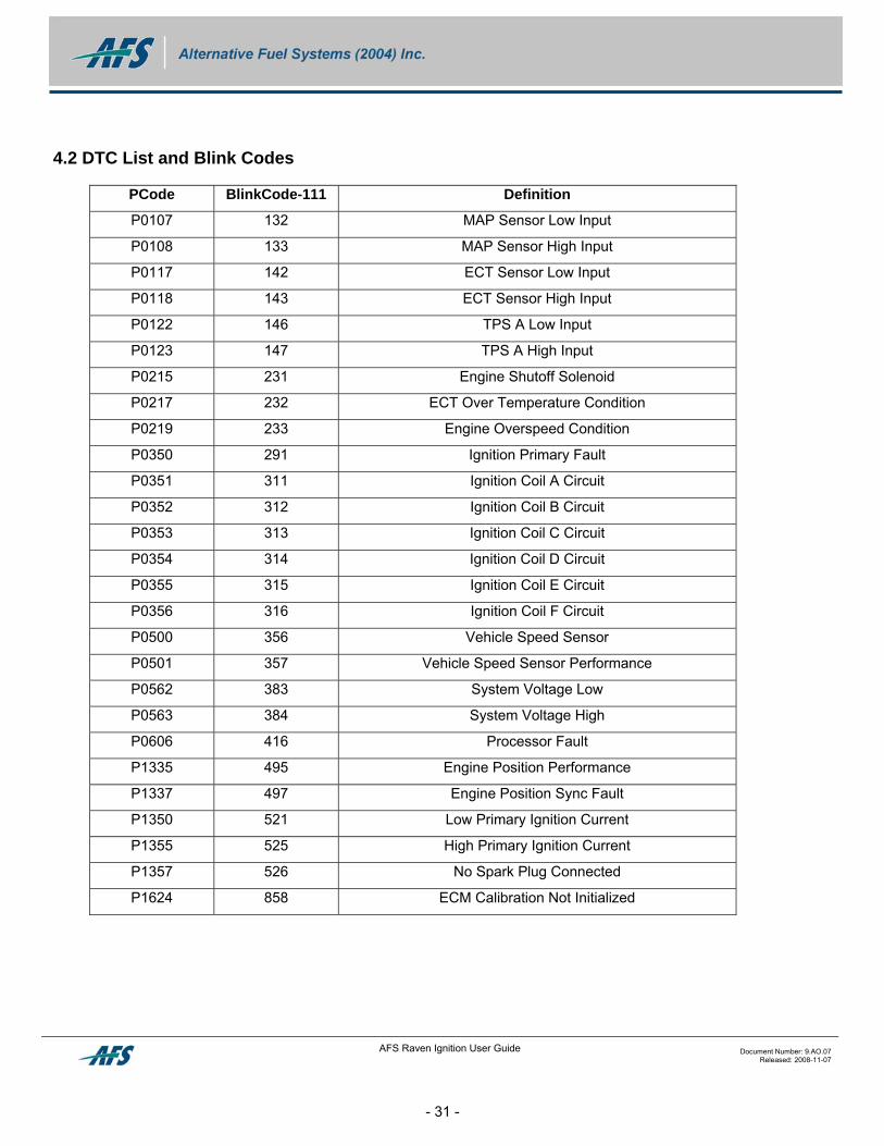
4.2 DTC List and Blink Codes
PCode BlinkCode-111 Definition
P0107 132 MAP Sensor Low Input
P0108 133 MAP Sensor High Input
P0117 142 ECT Sensor Low Input
P0118 143 ECT Sensor High Input
P0122 146 TPS A Low Input
P0123 147 TPS A High Input
P0215 231 Engine Shutoff Solenoid
P0217 232 ECT Over Temperature Condition
P0219 233 Engine Overspeed Condition
P0350 291 Ignition Primary Fault
P0351 311 Ignition Coil A Circuit
P0352 312 Ignition Coil B Circuit
P0353 313 Ignition Coil C Circuit
P0354 314 Ignition Coil D Circuit
P0355 315 Ignition Coil E Circuit
P0356 316 Ignition Coil F Circuit
P0500 356 Vehicle Speed Sensor
P0501 357 Vehicle Speed Sensor Performance
P0562 383 System Voltage Low
P0563 384 System Voltage High
P0606 416 Processor Fault
P1335 495 Engine Position Performance
P1337 497 Engine Position Sync Fault
P1350 521 Low Primary Ignition Current
P1355 525 High Primary Ignition Current
P1357 526 No Spark Plug Connected
P1624 858 ECM Calibration Not Initialized