Embed Size (px)
Citation preview
Page 1 1000001733 (Rev. F - 03/15)
EZSTLDWS*1D EZSTLRDWS*1D EZSTL8WS*1D, 2D, 3D EZSTLR8WS*1DLZSTLDWS*1D LZSTLRDWS*1D LZSTL8WS*1D, 2D, 3D LZSTLR8WS*1D
EZ™ & LZ™ Stations versatile de Remplissage de Bouteille Série et RefroidisseursEZ™ & LZ™ Serie versatil Botella Bombas y Enfriadores
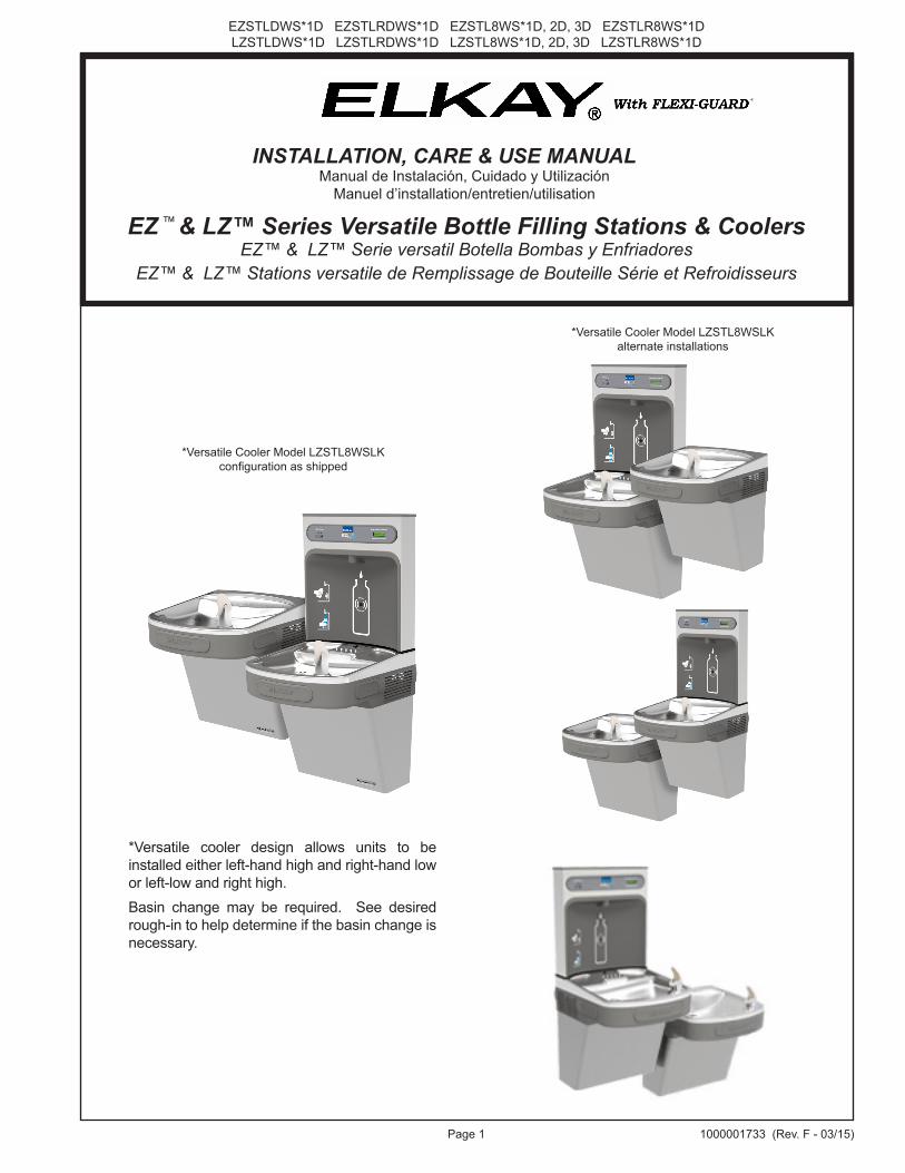
EZ ™ & LZ™ Series Versatile Bottle Filling Stations & Coolers
INSTALLATION, CARE & USE MANUALManual de Instalación, Cuidado y Utilización
Manuel d’installation/entretien/utilisation
*Versatile Cooler Model LZSTL8WSLK configuration as shipped
*Versatile Cooler Model LZSTL8WSLK alternate installations
*Versatile cooler design allows units to be installed either left-hand high and right-hand low or left-low and right high.Basin change may be required. See desired rough-in to help determine if the basin change isnecessary.
EZSTLDWS*1D EZSTLRDWS*1D EZSTL8WS*1D, 2D, 3D EZSTLR8WS*1DLZSTLDWS*1D LZSTLRDWS*1D LZSTL8WS*1D, 2D, 3D LZSTLR8WS*1D
Page 21000001733 (Rev. F - 03/15)
Uses HFC-R134A refrigerant Usa refrigerante HFC-R134A
Utilise du fluide frigorigéne HFC-R134A
19
8A1
See Fig. 9
2A
29
12
19
12
19
4
28
19
See Fig. 9
16
2B
14
12
36
Fig. 1
19
18
19
8B
211
15
16
13
5
365
1720
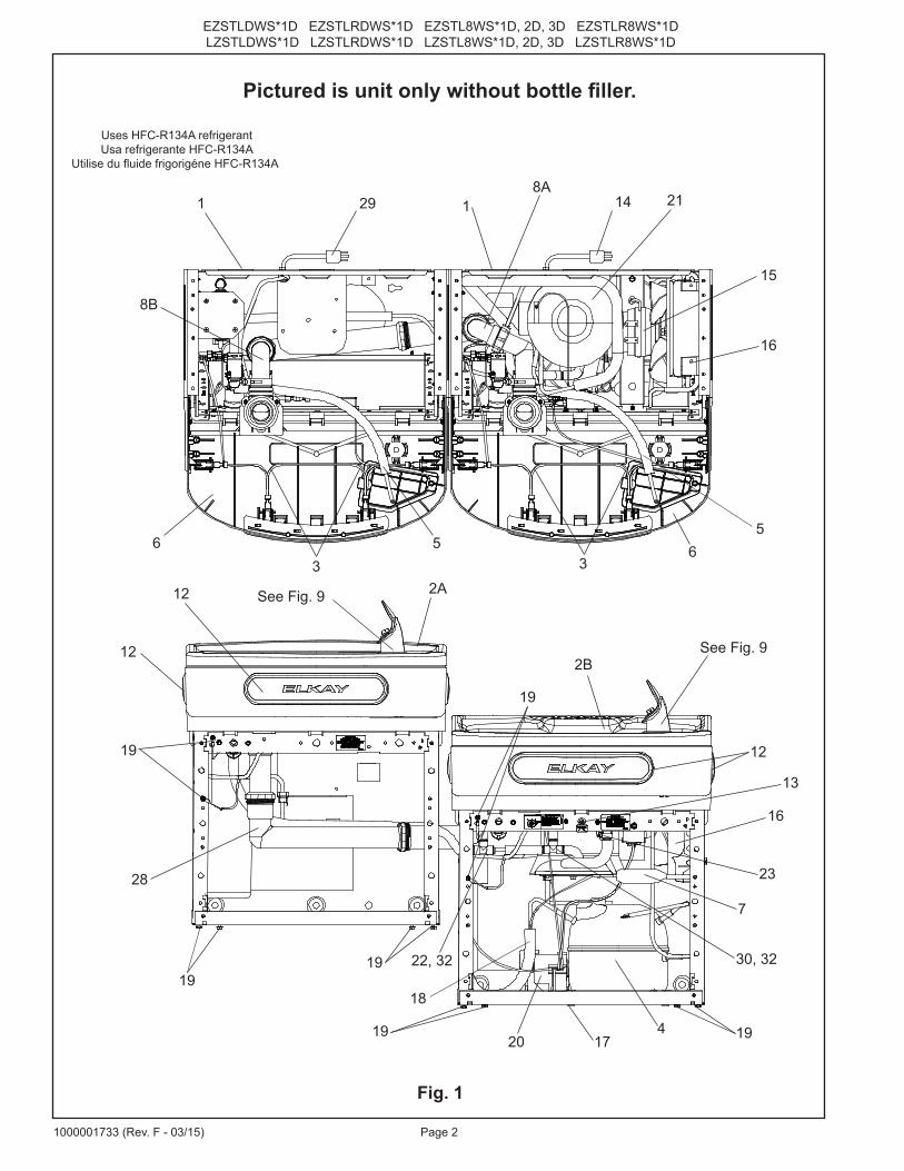
Pictured is unit only without bottle filler.
7
30, 3222, 32
23
Page 3 1000001733 (Rev. F - 03/15)
EZSTLDWS*1D EZSTLRDWS*1D EZSTL8WS*1D, 2D, 3D EZSTLR8WS*1DLZSTLDWS*1D LZSTLRDWS*1D LZSTL8WS*1D, 2D, 3D LZSTLR8WS*1D
17 7
/8"
454m
m
7"17
8mm
7"17
8mm
7/16
" X 3
/4"
11m
m X
19m
m
OBRO
UND
HOLE
S(6
)
15"
381m
m 2 7/
8"73
mm
2"51
mm
51 9
/16"
1310
mm
34 5
/16"
872m
m
24 1
/2"
622m
m 22 1
5/16
"58
3mm
19 7
/16"
494m
m
21 7
/8"
556m
m19
"48
3mm
28 1
3/16
"73
2mm
2"51
mm
17 7
/16"
443m
m13
15/
16"
354m
m
7"17
8mm
7"17
8mm
5 3/
4"14
6mm
2"51
mm
FINI
SHED
FLO
OR
6 3/
8"16
2mm
6 3/
8"16
2mm
‰
‰
2"51
mm 7/8"
22m
m
E
E
A(A
LT. L
OCAT
ION) F
DPR
EFER
RED
LOCA
TION
D (A
LT. L
OCAT
ION)
9/32
" Ø7m
m Ø
HOLE
S12
BA
PREF
ERRE
DLO
CATI
ON
12 1
/2"
318m
m3"
77m
m
1 7/
16"
37m
m
C
8 1/1
6"20
5mm
18 7
/8"
479m
m
3 9/
16"
90m
m
19"
483m
m
HANG
ER B
RACK
ET
32 7
/8"
835m
mOR
IFIC
EHE
IGHT 31
5/1
6"79
6mm
RIM
HEIG
HT
38 3
/8"
975m
mOR
IFIC
EHE
IGHT 36
13/
16"
936m
mRI
MHE
IGHT
OPTI
ONAL
FIL
TER
FILT
ER
6 3/
8"16
2mm
6 3/
8"16
2mm
18 3
/8"
467m
m
27"
686m
mAD
ARE
QUIR
EMEN
T
F3
7/8"
98m
m
ACTI
VATI
ON S
ENSO
R
38 1
/2"
979m
m
LEG
END
/LEY
END
A/L
ÉGEN
DE
A =
REC
OM
MEN
DED
WAT
ER S
UPP
LY L
OC
ATIO
N 3
/8 O
.D. U
NPL
ATED
CO
PPER
TU
BE
CO
NN
ECT
STU
B W
ITH
SH
UT
OFF
(BY
OTH
ERS)
3 IN
. (76
mm
) M
AXI
MU
M O
UT
FRO
M W
ALL
L
a U
BIC
AC
ION
3/8
O R
EC
OM
EN
DA
DA
de A
BA
STE
CIM
IEN
TO D
E A
GU
A. D
. El T
UB
O d
el C
OB
RE
de
UN
PLA
TED
CO
NE
CTA
TA
LON
AR
IO C
ON
APA
GO
(P
OR
OTR
OS
) 3 e
n. (7
6 M
m) e
l MA
XIM
O F
UE
RA
DE
PA
RE
D
L
’O.D
de
3/8
d’E
MP
LAC
EM
EN
T D
E P
RO
VIS
ION
D’E
AU
RE
CO
MM
AN
DE
. LE
TU
BE
DE
CU
IVR
E D
E U
NP
LATE
D C
ON
NE
CTE
STU
B A
VE
C E
TEIN
T (P
AR
LE
S A
UTR
ES
) 3 d
ans.
(76
mm
) le
MA
XIM
UM
HO
RS
DU
MU
RB
= R
ECO
MM
END
ED L
OC
ATIO
N F
OR
WA
STE
OU
TLET
1-1
/2”
O.D
. D
RA
IN S
TUB
2 IN
. OU
T FR
OM
WA
LLU
BIC
AC
IÓN
RE
CO
ME
ND
AD
A PA
RA
EL
DR
EN
AJE
DE
SA
LID
A D
E A
GU
A, D
E 1
-1/2
” DE
DIÁ
ME
TRO
. El T
ALO
NA
RIO
2 F
UE
RA
DE
PA
RE
DE
MP
LAC
EM
EN
T R
EC
OM
MA
ND
É P
OU
R L
E D
RA
IN D
E D
.E. 1
-1/2
” DE
SO
RTI
E D
’EA
U. S
TUB
2 H
OR
S D
U M
UR
C =
1-1
/2”
TRA
P N
OT
FUR
NIS
HED
PU
RG
AD
OR
DE
1-1
/2” N
O P
RO
PO
RC
ION
AD
OS
IPH
ON
1-1
/2” N
ON
FO
UR
NI
D =
ELE
CTR
ICA
L SU
PPLY
(3) W
IRE
REC
ESSE
D B
OX*
*C
AJA
RE
CE
SIV
A D
E A
LAM
BR
ES
(3) D
E S
UM
INIS
TRO
ELÉ
CTR
ICO
BO
ÎTE
EN
CA
STR
ÉE
D’A
LIM
EN
TATI
ON
ÉLE
CTR
IQU
E (3
) FIL
S
LEG
END
/LEY
END
A/L
ÉGEN
DE
D =
ELE
CTR
ICA
L SU
PPLY
(3) W
IRE
REC
ESSE
D B
OX*
*C
AJA
RE
CE
SIV
A D
E A
LAM
BR
ES
(3) D
E S
UM
INIS
TRO
ELÉ
CTR
ICO
BO
ÎTE
EN
CA
STR
ÉE
D’A
LIM
EN
TATI
ON
ÉLE
CTR
IQU
E (3
) FIL
SE
= IN
SUR
E PR
OPE
R V
ENTI
LATI
ON
BY
MA
INTA
ININ
G 6
” (1
52 m
m) (
MIN
.) C
LEA
RA
NC
E FR
OM
CA
BIN
ET L
OU
VER
S TO
WA
LL.
AS
EG
UR
E U
NA
VE
NTI
LAC
IÓN
AD
EC
UA
DA
MA
NTE
NIE
ND
O U
N E
SPA
CIO
E 6
” (15
2 m
m) (
MÍN
.) D
E H
OLG
UR
A E
NTR
E L
A R
EJI
LLA
DE
VE
NTI
LAC
IÓN
DE
L M
UE
BLE
Y L
A PA
RE
D.
AS
SU
RE
Z-V
OU
S U
NE
BO
NN
E V
EN
TILA
TIO
N E
N G
AR
DA
NT
6” (1
52 m
m) (
MIN
.) E
NTR
E L
ES
ÉV
EN
TS D
E L
’EN
CE
INTE
ET
LE M
UR
.F
= 7/
16 B
OLT
HO
LES
FOR
FA
STEN
ING
UN
IT T
O W
ALL
AG
UJE
RO
S D
E L
AS
TU
ER
CA
S D
E 7
/16
PAR
A S
UJE
TAR
LA
UN
IDA
D A
LA
PAR
ED
TRO
US
D’É
CR
OU
S 7
/16
PO
UR
FIX
ER
L’A
PPA
RE
IL A
U M
UR
**N
EW IN
STA
LLAT
ION
S M
UST
USE
GR
OU
ND
FA
ULT
CIR
CU
IT IN
TER
RU
PTER
(GFC
I)**
Las
nuev
as in
stal
acio
nes
debe
n ut
iliza
r el i
nter
rupt
or d
e ci
rcui
to d
e tie
rra
de la
ave
ría (G
FCI)
**Le
s no
uvel
les
inst
alla
tions
doi
vent
em
ploy
er l’
inte
rrup
teur
de
circ
uit m
oulu
de
défa
ut (G
FCI)
RED
UC
E H
EIG
HT
BY
3 IN
CH
ES F
OR
INST
ALL
ATIO
N O
F C
HIL
DR
ENS
AD
A C
OO
LER
STA
ND
AR
D R
OU
GH
-IN F
OR
LEF
T-H
AN
D H
IGH
, BO
TTLE
FIL
LER
LO
W M
OD
ELS
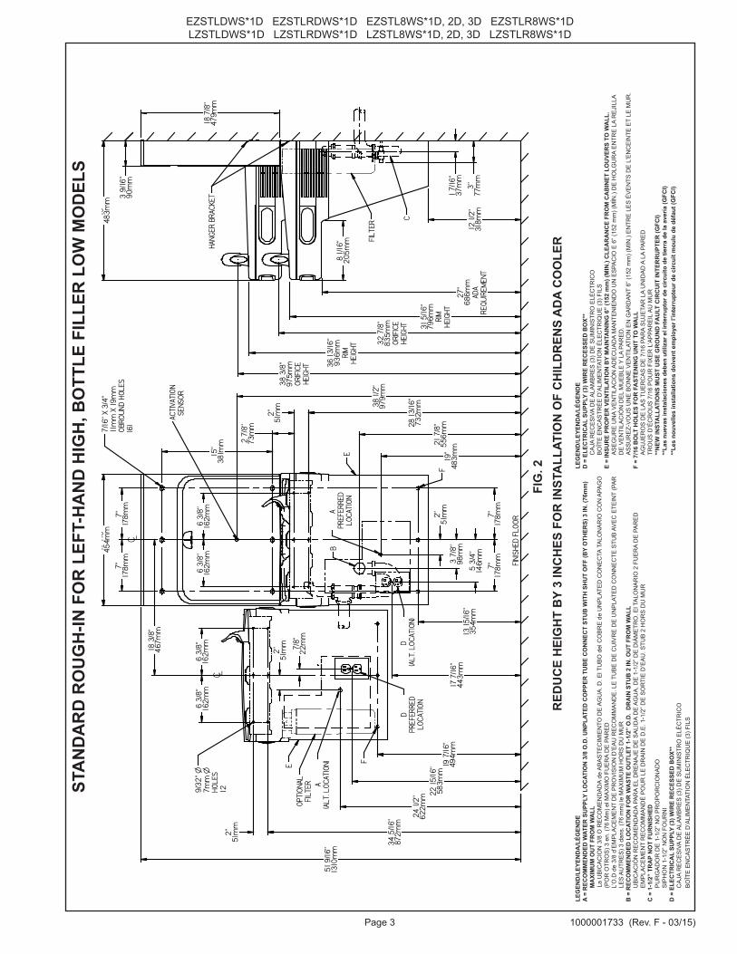
FIG
. 2
EZSTLDWS*1D EZSTLRDWS*1D EZSTL8WS*1D, 2D, 3D EZSTLR8WS*1DLZSTLDWS*1D LZSTLRDWS*1D LZSTL8WS*1D, 2D, 3D LZSTLR8WS*1D
Page 41000001733 (Rev. F - 03/15)
17 7
/8"
454m
m
7"17
8mm
7"17
8mm
7/16
" X 3
/4"
11m
m X
19m
m
OBRO
UND
HOL
ES(6
)
15"
381m
m
2 7/
8"73
mm
2"51
mm
51 9
/16"
1310
mm
28 1
3/16
"73
2mm
19"
483m
m17
7/16
"44
3mm
13 1
5/16
"35
4mm
24 1
/2"
622m
m34 5
/16"
872m
m
2"51
mm
22 1
5/16
"58
3mm
19 7
/16"
494m
m
7"17
8mm
7"17
8mm
5 3/
4"14
6mm
2"51
mm
FINI
SHED
FLO
OR
18 3
/8"
467m
m
6 3/
8"16
2mm
6 3/
8"16
2mm
6 3/
8"16
2mm
‰
‰
6 3/
8"16
2mm
2"51
mm 7/8"
22m
m
E
E
A(A
LT. L
OCAT
ION)
F
DPR
EFER
RED
LOCA
TION
D (A
LT. L
OCAT
ION)
9/32
" Ø7m
m Ø
HOLE
S12
A PR
EFER
RED
LOCA
TION
12 1
/2"
318m
m3"
76m
m
C
3 9/
16"
90m
m
19"
483m
m
HANG
ER B
RACK
ET
31 5
/16"
796m
mRI
MHE
IGHT
38 3
/8"
975m
mOR
IFIC
EHE
IGHT 36
13/
16"
936m
mRI
MHE
IGHT
OPTI
ONAL
FIL
TER
32 7
/8"
835m
mOR
IFIC
EHE
IGHT
1 7/
16"
37m
m
8 1/1
6"20
5mm FILT
ER
B
18 7
/8"
479m
m
27"
686m
mAD
ARE
QUIR
EMEN
T
F21
7/8
"55
6mm
3 7/
8"98
mm
ACTI
VATI
ON S
ENSO
R
38 1
/2"
979m
m
LEG
END
/LEY
END
A/L
ÉGEN
DE
A =
REC
OM
MEN
DED
WAT
ER S
UPP
LY L
OC
ATIO
N 3
/8 O
.D. U
NPL
ATED
CO
PPER
TU
BE
CO
NN
ECT
STU
B W
ITH
SH
UT
OFF
(BY
OTH
ERS)
3 IN
. (76
mm
) M
AXI
MU
M O
UT
FRO
M W
ALL
L
a U
BIC
AC
ION
3/8
O R
EC
OM
EN
DA
DA
de A
BA
STE
CIM
IEN
TO D
E A
GU
A. D
. El T
UB
O d
el C
OB
RE
de
UN
PLA
TED
CO
NE
CTA
TA
LON
AR
IO C
ON
APA
GO
(P
OR
OTR
OS
) 3 e
n. (7
6 M
m) e
l MA
XIM
O F
UE
RA
DE
PA
RE
D
L
’O.D
de
3/8
d’E
MP
LAC
EM
EN
T D
E P
RO
VIS
ION
D’E
AU
RE
CO
MM
AN
DE
. LE
TU
BE
DE
CU
IVR
E D
E U
NP
LATE
D C
ON
NE
CTE
STU
B A
VE
C E
TEIN
T (P
AR
LE
S A
UTR
ES
) 3 d
ans.
(76
mm
) le
MA
XIM
UM
HO
RS
DU
MU
RB
= R
ECO
MM
END
ED L
OC
ATIO
N F
OR
WA
STE
OU
TLET
1-1
/2”
O.D
. D
RA
IN S
TUB
2 IN
. OU
T FR
OM
WA
LL U
BIC
AC
IÓN
RE
CO
ME
ND
AD
A PA
RA
EL
DR
EN
AJE
DE
SA
LID
A D
E A
GU
A, D
E 1
-1/2
” DE
DIÁ
ME
TRO
. El T
ALO
NA
RIO
2 F
UE
RA
DE
PA
RE
DE
MP
LAC
EM
EN
T R
EC
OM
MA
ND
É P
OU
R L
E D
RA
IN D
E D
.E. 1
-1/2
” DE
SO
RTI
E D
’EA
U. S
TUB
2 H
OR
S D
U M
UR
C =
1-1
/2”
TRA
P N
OT
FUR
NIS
HED
PU
RG
AD
OR
DE
1-1
/2” N
O P
RO
PO
RC
ION
AD
OS
IPH
ON
1-1
/2” N
ON
FO
UR
NI
D =
ELE
CTR
ICA
L SU
PPLY
(3) W
IRE
REC
ESSE
D B
OX*
*C
AJA
RE
CE
SIV
A D
E A
LAM
BR
ES
(3) D
E S
UM
INIS
TRO
ELÉ
CTR
ICO
BO
ÎTE
EN
CA
STR
ÉE
D’A
LIM
EN
TATI
ON
ÉLE
CTR
IQU
E (3
) FIL
S
LEG
END
/LEY
END
A/L
ÉGEN
DE
D =
ELE
CTR
ICA
L SU
PPLY
(3) W
IRE
REC
ESSE
D B
OX*
*C
AJA
RE
CE
SIV
A D
E A
LAM
BR
ES
(3) D
E S
UM
INIS
TRO
ELÉ
CTR
ICO
BO
ÎTE
EN
CA
STR
ÉE
D’A
LIM
EN
TATI
ON
ÉLE
CTR
IQU
E (3
) FIL
SE
= IN
SUR
E PR
OPE
R V
ENTI
LATI
ON
BY
MA
INTA
ININ
G 6
” (1
52 m
m) (
MIN
.) C
LEA
RA
NC
E FR
OM
CA
BIN
ET L
OU
VER
S TO
WA
LL.
AS
EG
UR
E U
NA
VE
NTI
LAC
IÓN
AD
EC
UA
DA
MA
NTE
NIE
ND
O U
N E
SPA
CIO
E 6
” (15
2 m
m) (
MÍN
.) D
E H
OLG
UR
A E
NTR
E L
A R
EJI
LLA
DE
VE
NTI
LAC
IÓN
DE
L M
UE
BLE
Y L
A PA
RE
D.
AS
SU
RE
Z-V
OU
S U
NE
BO
NN
E V
EN
TILA
TIO
N E
N G
AR
DA
NT
6” (1
52 m
m) (
MIN
.) E
NTR
E L
ES
ÉV
EN
TS D
E L
’EN
CE
INTE
ET
LE M
UR
.F
= 7/
16 B
OLT
HO
LES
FOR
FA
STEN
ING
UN
IT T
O W
ALL
AG
UJE
RO
S D
E L
AS
TU
ER
CA
S D
E 7
/16
PAR
A S
UJE
TAR
LA
UN
IDA
D A
LA
PAR
ED
TRO
US
D’É
CR
OU
S 7
/16
PO
UR
FIX
ER
L’A
PPA
RE
IL A
U M
UR
**N
EW IN
STA
LLAT
ION
S M
UST
USE
GR
OU
ND
FA
ULT
CIR
CU
IT IN
TER
RU
PTER
(GFC
I)**
Las
nuev
as in
stal
acio
nes
debe
n ut
iliza
r el i
nter
rupt
or d
e ci
rcui
to d
e tie
rra
de la
ave
ría (G
FCI)
**Le
s no
uvel
les
inst
alla
tions
doi
vent
em
ploy
er l’
inte
rrup
teur
de
circ
uit m
oulu
de
défa
ut (G
FCI)
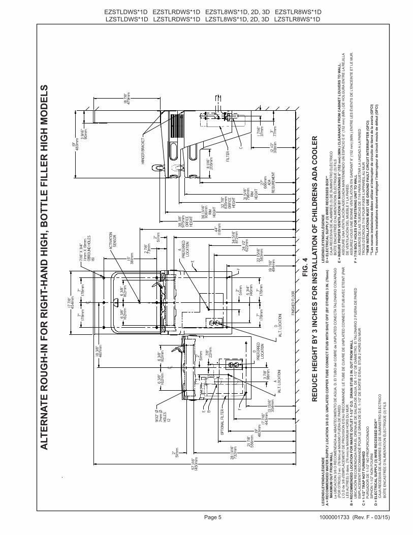
RED
UC
E H
EIG
HT
BY
3 IN
CH
ES F
OR
INST
ALL
ATIO
N O
F C
HIL
DR
ENS
AD
A C
OO
LER
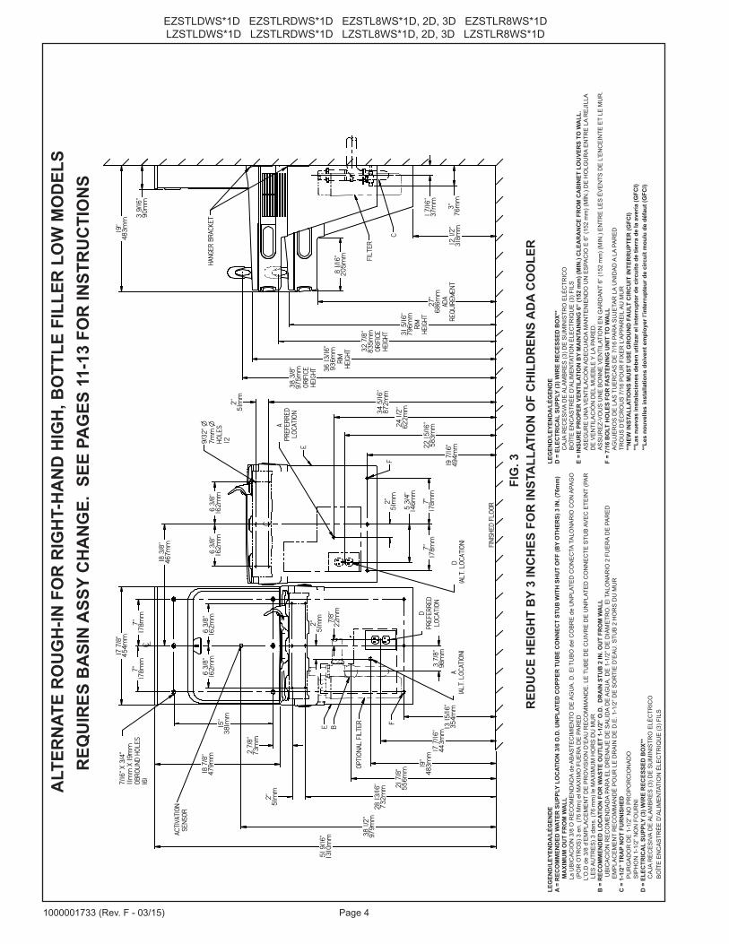
ALT
ERN
ATE
RO
UG
H-IN
FO
R R
IGH
T-H
AN
D H
IGH
, BO
TTLE
FIL
LER
LO
W M
OD
ELS
FIG
. 3
REQ
UIR
ES B
ASI
N A
SSY
CH
AN
GE.
SEE
PA
GES
11-
13 F
OR
INST
RU
CTI
ON
S
Page 5 1000001733 (Rev. F - 03/15)
EZSTLDWS*1D EZSTLRDWS*1D EZSTL8WS*1D, 2D, 3D EZSTLR8WS*1DLZSTLDWS*1D LZSTLRDWS*1D LZSTL8WS*1D, 2D, 3D LZSTLR8WS*1D
7/16
" X 3
/4"
11m
m X
19m
m
OBRO
UND
HOLE
S(6
)
2"51
mm
28 1
3/16
"73
2mm
19"
483m
m17
7/16
"44
3mm
13 1
5/16
"35
4mm
24 1
/2"
622m
m34 5
/16"
872m
m
2"51
mm
22 1
5/16
"58
3mm
19 7
/16"
494m
m
7"17
8mm
7"17
8mm
5 3/
4"14
6mm
2"51
mm
FINI
SHED
FLO
OR
6 3/
8"16
2mm
6 3/
8"16
2mm
‰
‰
2"51
mm 7/8"
22m
m
E
E
A(A
LT. L
OCAT
ION)
F
DPR
EFER
RED
LOCA
TION
D (A
LT. L
OCAT
ION)
9/32
" Ø7m
m Ø
HOLE
S12
A PR
EFER
RED
LOCA
TION
C
HANG
ER B
RACK
ET
OPTI
ONAL
FIL
TER
FILT
ER
B
12 1
/2"
318m
m
1 7/
16"
37m
m
3"77
mm
18 7
/8"
479m
m
3 9/
16"
90m
m
19"
483m
m
8 1/
16"
205m
m
27"
686m
mAD
ARE
QUIR
EMEN
T
31 5
/16"
796m
mRI
MHE
IGHT
32 7
/8"
835m
mOR
IFIC
E HE
IGHT
36 1
3/16
"93
6mm
RIM
HEIG
HT
38 3
/8"
975m
mOR
FICE
HEIG
HT
17 7
/8"
454m
m
7"17
8mm
7"17
8mm
6 3/
8"16
2mm
6 3/
8"16
2mm
18 3
/8"
467m
m
15"
381m
m
2 7/
8"73
mm
F
21 7
/8"
556m
m
3 7/
8"98
mm
57 1
/16"
1450
mm
ACTI
VATI
ON S
ENSO
R
44"
1118
mm
LEG
END
/LEY
END
A/L
ÉGEN
DE
A =
REC
OM
MEN
DED
WAT
ER S
UPP
LY L
OC
ATIO
N 3
/8 O
.D. U
NPL
ATED
CO
PPER
TU
BE
CO
NN
ECT
STU
B W
ITH
SH
UT
OFF
(BY
OTH
ERS)
3 IN
. (76
mm
) M
AXI
MU
M O
UT
FRO
M W
ALL
L
a U
BIC
AC
ION
3/8
O R
EC
OM
EN
DA
DA
de A
BA
STE
CIM
IEN
TO D
E A
GU
A. D
. El T
UB
O d
el C
OB
RE
de
UN
PLA
TED
CO
NE
CTA
TA
LON
AR
IO C
ON
APA
GO
(P
OR
OTR
OS
) 3 e
n. (7
6 M
m) e
l MA
XIM
O F
UE
RA
DE
PA
RE
D
L
’O.D
de
3/8
d’E
MP
LAC
EM
EN
T D
E P
RO
VIS
ION
D’E
AU
RE
CO
MM
AN
DE
. LE
TU
BE
DE
CU
IVR
E D
E U
NP
LATE
D C
ON
NE
CTE
STU
B A
VE
C E
TEIN
T (P
AR
LE
S A
UTR
ES
) 3 d
ans.
(76
mm
) le
MA
XIM
UM
HO
RS
DU
MU
RB
= R
ECO
MM
END
ED L
OC
ATIO
N F
OR
WA
STE
OU
TLET
1-1
/2”
O.D
. D
RA
IN S
TUB
2 IN
. OU
T FR
OM
WA
LL U
BIC
AC
IÓN
RE
CO
ME
ND
AD
A PA
RA
EL
DR
EN
AJE
DE
SA
LID
A D
E A
GU
A, D
E 1
-1/2
” DE
DIÁ
ME
TRO
. El T
ALO
NA
RIO
2 F
UE
RA
DE
PA
RE
D E
MP
LAC
EM
EN
T R
EC
OM
MA
ND
É P
OU
R L
E D
RA
IN D
E D
.E. 1
-1/2
” DE
SO
RTI
E D
’EA
U. S
TUB
2 H
OR
S D
U M
UR
C =
1-1
/2”
TRA
P N
OT
FUR
NIS
HED
PU
RG
AD
OR
DE
1-1
/2” N
O P
RO
PO
RC
ION
AD
O S
IPH
ON
1-1
/2” N
ON
FO
UR
NI
D =
ELE
CTR
ICA
L SU
PPLY
(3) W
IRE
REC
ESSE
D B
OX*
*C
AJA
RE
CE
SIV
A D
E A
LAM
BR
ES
(3) D
E S
UM
INIS
TRO
ELÉ
CTR
ICO
BO
ÎTE
EN
CA
STR
ÉE
D’A
LIM
EN
TATI
ON
ÉLE
CTR
IQU
E (3
) FIL
S
LEG
END
/LEY
END
A/L
ÉGEN
DE
D =
ELE
CTR
ICA
L SU
PPLY
(3) W
IRE
REC
ESSE
D B
OX*
*C
AJA
RE
CE
SIV
A D
E A
LAM
BR
ES
(3) D
E S
UM
INIS
TRO
ELÉ
CTR
ICO
BO
ÎTE
EN
CA
STR
ÉE
D’A
LIM
EN
TATI
ON
ÉLE
CTR
IQU
E (3
) FIL
SE
= IN
SUR
E PR
OPE
R V
ENTI
LATI
ON
BY
MA
INTA
ININ
G 6
” (1
52 m
m) (
MIN
.) C
LEA
RA
NC
E FR
OM
CA
BIN
ET L
OU
VER
S TO
WA
LL.
AS
EG
UR
E U
NA
VE
NTI
LAC
IÓN
AD
EC
UA
DA
MA
NTE
NIE
ND
O U
N E
SPA
CIO
E 6
” (15
2 m
m) (
MÍN
.) D
E H
OLG
UR
A E
NTR
E L
A R
EJI
LLA
DE
VE
NTI
LAC
IÓN
DE
L M
UE
BLE
Y L
A PA
RE
D.
AS
SU
RE
Z-V
OU
S U
NE
BO
NN
E V
EN
TILA
TIO
N E
N G
AR
DA
NT
6” (1
52 m
m) (
MIN
.) E
NTR
E L
ES
ÉV
EN
TS D
E L
’EN
CE
INTE
ET
LE M
UR
.F
= 7/
16 B
OLT
HO
LES
FOR
FA
STEN
ING
UN
IT T
O W
ALL
AG
UJE
RO
S D
E L
AS
TU
ER
CA
S D
E 7
/16
PAR
A S
UJE
TAR
LA
UN
IDA
D A
LA
PAR
ED
TRO
US
D’É
CR
OU
S 7
/16
PO
UR
FIX
ER
L’A
PPA
RE
IL A
U M
UR
**N
EW IN
STA
LLAT
ION
S M
UST
USE
GR
OU
ND
FA
ULT
CIR
CU
IT IN
TER
RU
PTER
(GFC
I)**
Las
nuev
as in
stal
acio
nes
debe
n ut
iliza
r el i
nter
rupt
or d
e ci
rcui
to d
e tie
rra
de la
ave
ría (G
FCI)
**Le
s no
uvel
les
inst
alla
tions
doi
vent
em
ploy
er l’
inte
rrup
teur
de
circ
uit m
oulu
de
défa
ut (G
FCI)
RED
UC
E H
EIG
HT
BY
3 IN
CH
ES F
OR
INST
ALL
ATIO
N O
F C
HIL
DR
ENS
AD
A C
OO
LER
ALT
ERN
ATE
RO
UG
H-IN
FO
R R
IGH
T-H
AN
D H
IGH
, BO
TTLE
FIL
LER
HIG
H M
OD
ELS
FIG
. 4
EZSTLDWS*1D EZSTLRDWS*1D EZSTL8WS*1D, 2D, 3D EZSTLR8WS*1DLZSTLDWS*1D LZSTLRDWS*1D LZSTL8WS*1D, 2D, 3D LZSTLR8WS*1D
Page 61000001733 (Rev. F - 03/15)
17 7
/8"
454m
m
7"17
8mm
7"17
8mm
7/16
" X 3
/4"
11m
m X
19m
m
OBRO
UND
HOLE
S(6
)
15"
381m
m
2 7/
8"73
mm
2"51
mm
57 1
/16"
1450
mm
34 5
/16"
872m
m
24 1
/2"
622m
m 22 1
5/16
"58
3mm
19 7
/16"
494m
m
21 7
/8"
556m
m19
"48
3mm
28 1
3/16
"73
2mm
2"51
mm
17 7
/16"
443m
m13
15/
16"
354m
m
7"17
8mm
7"17
8mm
5 3/
4"14
6mm
2"51
mm
FINI
SHED
FLO
OR
18 3
/8"
467m
m
6 3/
8"16
2mm
6 3/
8"16
2mm
6 3/
8"16
2mm
‰
‰
6 3/
8"16
2mm
2"51
mm 7/8"
22m
m
E
E
A(A
LT. L
OCAT
ION) F
DPR
EFER
RED
LOCA
TION
D (A
LT. L
OCAT
ION)
9/32
" Ø7m
m Ø
HOLE
S12
BA
PREF
ERRE
DLO
CATI
ON
12 1
/2"
318m
m3"
77m
m
1 7/
16"
37m
m
C
8 1/1
6"20
5mm
18 7
/8"
479m
m
3 9/
16"
90m
m
19"
483m
m
HANG
ER B
RACK
ET
38 3
/8"
975m
mOR
IFIC
EHE
IGHT 36
13/
16"
935m
mRI
MHE
IGHT 32
7/8
"83
5mm
ORIF
ICE
HEIG
HT 31 5
/16"
796m
mRI
MHE
IGHT
FIL
TER
FILT
ER
27"
686m
mAD
ARE
QUIR
EMEN
T
F
3 7/
8"98
mm
ACTI
VATI
ON S
ENSO
R
44"
1118
mm
LEG
END
/LEY
END
A/L
ÉGEN
DE
A =
REC
OM
MEN
DED
WAT
ER S
UPP
LY L
OC
ATIO
N 3
/8 O
.D. U
NPL
ATED
CO
PPER
TU
BE
CO
NN
ECT
STU
B W
ITH
SH
UT
OFF
(BY
OTH
ERS)
3 IN
. (76
mm
) M
AXI
MU
M O
UT
FRO
M W
ALL
L
a U
BIC
AC
ION
3/8
O R
EC
OM
EN
DA
DA
de A
BA
STE
CIM
IEN
TO D
E A
GU
A. D
. El T
UB
O d
el C
OB
RE
de
UN
PLA
TED
CO
NE
CTA
TA
LON
AR
IO C
ON
APA
GO
(P
OR
OTR
OS
) 3 e
n. (7
6 M
m) e
l MA
XIM
O F
UE
RA
DE
PA
RE
D
L
’O.D
de
3/8
d’E
MP
LAC
EM
EN
T D
E P
RO
VIS
ION
D’E
AU
RE
CO
MM
AN
DE
. LE
TU
BE
DE
CU
IVR
E D
E U
NP
LATE
D C
ON
NE
CTE
STU
B A
VE
C E
TEIN
T (P
AR
LE
S A
UTR
ES
) 3 d
ans.
(76
mm
) le
MA
XIM
UM
HO
RS
DU
MU
RB
= R
ECO
MM
END
ED L
OC
ATIO
N F
OR
WA
STE
OU
TLET
1-1
/2”
O.D
. D
RA
IN S
TUB
2 IN
. OU
T FR
OM
WA
LL U
BIC
AC
IÓN
RE
CO
ME
ND
AD
A PA
RA
EL
DR
EN
AJE
DE
SA
LID
A D
E A
GU
A, D
E 1
-1/2
” DE
DIÁ
ME
TRO
. El T
ALO
NA
RIO
2 F
UE
RA
DE
PA
RE
DE
MP
LAC
EM
EN
T R
EC
OM
MA
ND
É P
OU
R L
E D
RA
IN D
E D
.E. 1
-1/2
” DE
SO
RTI
E D
’EA
U. S
TUB
2 H
OR
S D
U M
UR
C =
1-1
/2”
TRA
P N
OT
FUR
NIS
HED
PU
RG
AD
OR
DE
1-1
/2” N
O P
RO
PO
RC
ION
AD
OS
IPH
ON
1-1
/2” N
ON
FO
UR
NI
D =
ELE
CTR
ICA
L SU
PPLY
(3) W
IRE
REC
ESSE
D B
OX*
*C
AJA
RE
CE
SIV
A D
E A
LAM
BR
ES
(3) D
E S
UM
INIS
TRO
ELÉ
CTR
ICO
BO
ÎTE
EN
CA
STR
ÉE
D’A
LIM
EN
TATI
ON
ÉLE
CTR
IQU
E (3
) FIL
S
LEG
END
/LEY
END
A/L
ÉGEN
DE
D =
ELE
CTR
ICA
L SU
PPLY
(3) W
IRE
REC
ESSE
D B
OX*
*C
AJA
RE
CE
SIV
A D
E A
LAM
BR
ES
(3) D
E S
UM
INIS
TRO
ELÉ
CTR
ICO
BO
ÎTE
EN
CA
STR
ÉE
D’A
LIM
EN
TATI
ON
ÉLE
CTR
IQU
E (3
) FIL
SE
= IN
SUR
E PR
OPE
R V
ENTI
LATI
ON
BY
MA
INTA
ININ
G 6
” (1
52 m
m) (
MIN
.) C
LEA
RA
NC
E FR
OM
CA
BIN
ET L
OU
VER
S TO
WA
LL.
AS
EG
UR
E U
NA
VE
NTI
LAC
IÓN
AD
EC
UA
DA
MA
NTE
NIE
ND
O U
N E
SPA
CIO
E 6
” (15
2 m
m) (
MÍN
.) D
E H
OLG
UR
A E
NTR
E L
A R
EJI
LLA
DE
VE
NTI
LAC
IÓN
DE
L M
UE
BLE
Y L
A PA
RE
D.
AS
SU
RE
Z-V
OU
S U
NE
BO
NN
E V
EN
TILA
TIO
N E
N G
AR
DA
NT
6” (1
52 m
m) (
MIN
.) E
NTR
E L
ES
ÉV
EN
TS D
E L
’EN
CE
INTE
ET
LE M
UR
.F
= 7/
16 B
OLT
HO
LES
FOR
FA
STEN
ING
UN
IT T
O W
ALL
AG
UJE
RO
S D
E L
AS
TU
ER
CA
S D
E 7
/16
PAR
A S
UJE
TAR
LA
UN
IDA
D A
LA
PAR
ED
TRO
US
D’É
CR
OU
S 7
/16
PO
UR
FIX
ER
L’A
PPA
RE
IL A
U M
UR
**N
EW IN
STA
LLAT
ION
S M
UST
USE
GR
OU
ND
FA
ULT
CIR
CU
IT IN
TER
RU
PTER
(GFC
I)**
Las
nuev
as in
stal
acio
nes
debe
n ut
iliza
r el i
nter
rupt
or d
e ci
rcui
to d
e tie
rra
de la
ave
ría (G
FCI)
**Le
s no
uvel
les
inst
alla
tions
doi
vent
em
ploy
er l’
inte
rrup
teur
de
circ
uit m
oulu
de
défa
ut (G
FCI)
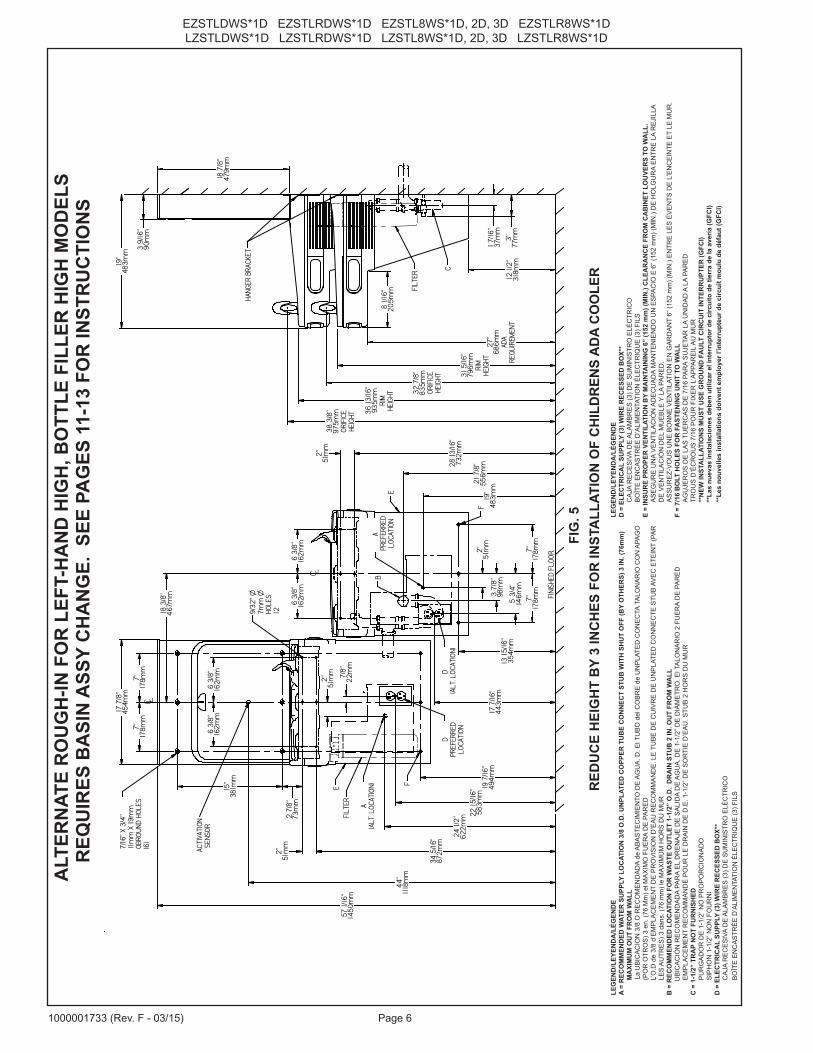
RED
UC
E H
EIG
HT
BY
3 IN
CH
ES F
OR
INST
ALL
ATIO
N O
F C
HIL
DR
ENS
AD
A C
OO
LER
ALT
ERN
ATE
RO
UG
H-IN
FO
R L
EFT-
HA
ND
HIG
H, B
OTT
LE F
ILLE
R H
IGH
MO
DEL
S
FIG
. 5
REQ
UIR
ES B
ASI
N A
SSY
CH
AN
GE.
SEE
PA
GES
11-
13 F
OR
INST
RU
CTI
ON
S
Page 7 1000001733 (Rev. F - 03/15)
EZSTLDWS*1D EZSTLRDWS*1D EZSTL8WS*1D, 2D, 3D EZSTLR8WS*1DLZSTLDWS*1D LZSTLRDWS*1D LZSTL8WS*1D, 2D, 3D LZSTLR8WS*1D
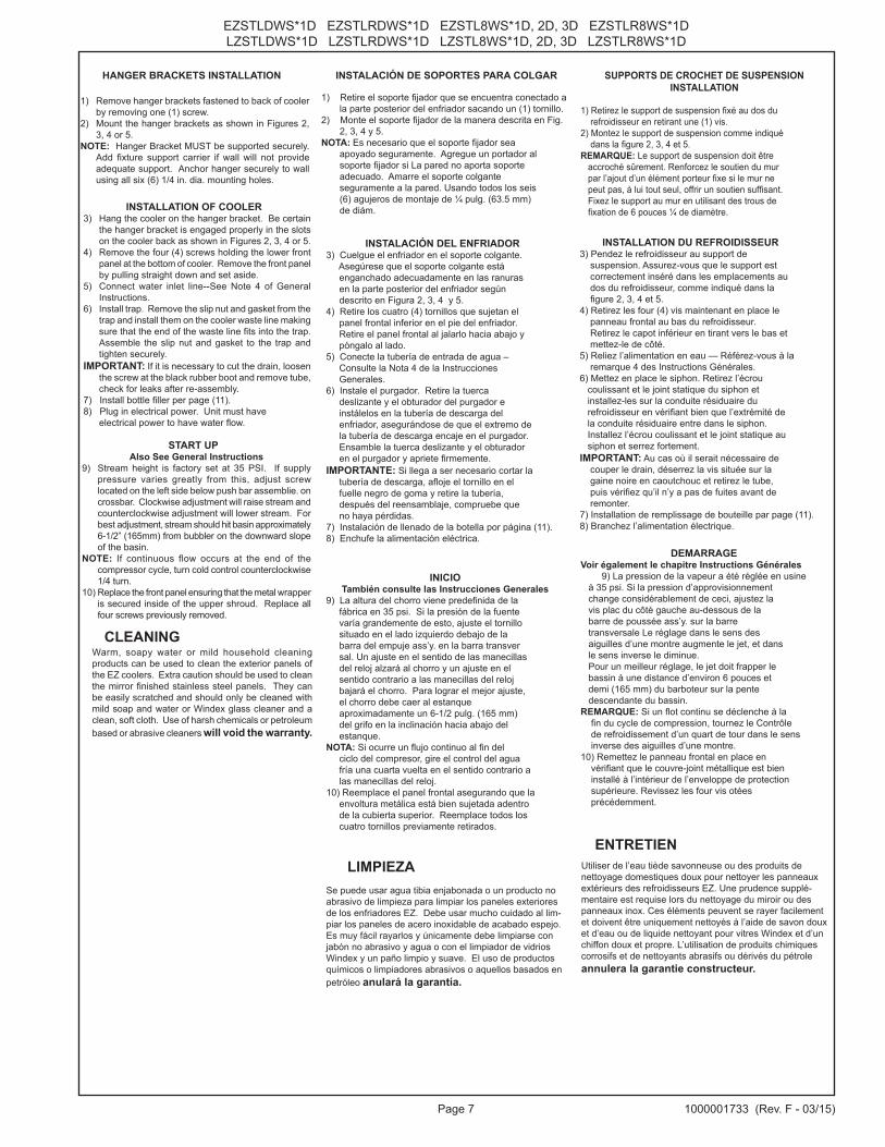
INSTALACIÓN DE SOPORTES PARA COLGAR
1) Retire el soporte fijador que se encuentra conectado a la parte posterior del enfriador sacando un (1) tornillo.2) Monte el soporte fijador de la manera descrita en Fig. 2, 3, 4 y 5.NOTA: Es necesario que el soporte fijador sea apoyado seguramente. Agregue un portador al soporte fijador si La pared no aporta soporte adecuado. Amarre el soporte colgante seguramente a la pared. Usando todos los seis (6) agujeros de montaje de ¼ pulg. (63.5 mm) de diám.
INSTALACIÓN DEL ENFRIADOR3) Cuelgue el enfriador en el soporte colgante. Asegúrese que el soporte colgante está enganchado adecuadamente en las ranuras en la parte posterior del enfriador según descrito en Figura 2, 3, 4 y 5.4) Retire los cuatro (4) tornillos que sujetan el panel frontal inferior en el pie del enfriador. Retire el panel frontal al jalarlo hacia abajo y póngalo al lado.5) Conecte la tubería de entrada de agua – Consulte la Nota 4 de la Instrucciones Generales.6) Instale el purgador. Retire la tuerca deslizante y el obturador del purgador e instálelos en la tubería de descarga del enfriador, asegurándose de que el extremo de la tubería de descarga encaje en el purgador. Ensamble la tuerca deslizante y el obturador en el purgador y apriete firmemente.IMPORTANTE: Si llega a ser necesario cortar la tubería de descarga, afloje el tornillo en el fuelle negro de goma y retire la tubería, después del reensamblaje, compruebe que no haya pérdidas.7) Instalación de llenado de la botella por página (11).8) Enchufe la alimentación eléctrica.
INICIO También consulte las Instrucciones Generales
9) La altura del chorro viene predefinida de la fábrica en 35 psi. Si la presión de la fuente varía grandemente de esto, ajuste el tornillo situado en el lado izquierdo debajo de la barra del empuje ass’y. en la barra transver sal. Un ajuste en el sentido de las manecillas del reloj alzará al chorro y un ajuste en el sentido contrario a las manecillas del reloj bajará el chorro. Para lograr el mejor ajuste, el chorro debe caer al estanque aproximadamente un 6-1/2 pulg. (165 mm) del grifo en la inclinación hacia abajo del estanque.NOTA: Si ocurre un flujo continuo al fin del ciclo del compresor, gire el control del agua fría una cuarta vuelta en el sentido contrario a las manecillas del reloj.10) Reemplace el panel frontal asegurando que la envoltura metálica está bien sujetada adentro de la cubierta superior. Reemplace todos los cuatro tornillos previamente retirados.
SUPPORTS DE CROCHET DE SUSPENSION INSTALLATION
1) Retirez le support de suspension fixé au dos du refroidisseur en retirant une (1) vis. 2) Montez le support de suspension comme indiqué dans la figure 2, 3, 4 et 5. REMARQUE: Le support de suspension doit être accroché sûrement. Renforcez le soutien du mur par l’ajout d’un élément porteur fixe si le mur ne peut pas, à lui tout seul, offrir un soutien suffisant. Fixez le support au mur en utilisant des trous de fixation de 6 pouces ¼ de diamètre.
INSTALLATION DU REFROIDISSEUR 3) Pendez le refroidisseur au support de suspension. Assurez-vous que le support est correctement inséré dans les emplacements au dos du refroidisseur, comme indiqué dans la figure 2, 3, 4 et 5. 4) Retirez les four (4) vis maintenant en place le panneau frontal au bas du refroidisseur. Retirez le capot inférieur en tirant vers le bas et mettez-le de côté. 5) Reliez l’alimentation en eau — Référez-vous à la remarque 4 des Instructions Générales. 6) Mettez en place le siphon. Retirez l’écrou coulissant et le joint statique du siphon et installez-les sur la conduite résiduaire du refroidisseur en vérifiant bien que l’extrémité de la conduite résiduaire entre dans le siphon. Installez l’écrou coulissant et le joint statique au siphon et serrez fortement. IMPORTANT: Au cas où il serait nécessaire de couper le drain, déserrez la vis située sur la gaine noire en caoutchouc et retirez le tube, puis vérifiez qu’il n’y a pas de fuites avant de remonter. 7) Installation de remplissage de bouteille par page (11).8) Branchez l’alimentation électrique.
DEMARRAGE
Voir également le chapitre Instructions Générales 9) La pression de la vapeur a été réglée en usine
à 35 psi. Si la pression d’approvisionnement change considérablement de ceci, ajustez la vis plac du côté gauche au-dessous de la barre de poussée ass’y. sur la barre transversale Le réglage dans le sens des aiguilles d’une montre augmente le jet, et dans le sens inverse le diminue. Pour un meilleur réglage, le jet doit frapper le bassin à une distance d’environ 6 pouces et demi (165 mm) du barboteur sur la pente descendante du bassin. REMARQUE: Si un flot continu se déclenche à la fin du cycle de compression, tournez le Contrôle de refroidissement d’un quart de tour dans le sens inverse des aiguilles d’une montre. 10) Remettez le panneau frontal en place en vérifiant que le couvre-joint métallique est bien installé à l’intérieur de l’enveloppe de protection supérieure. Revissez les four vis otées précédemment.
LIMPIEZAENTRETIEN
Se puede usar agua tibia enjabonada o un producto no abrasivo de limpieza para limpiar los paneles exteriores de los enfriadores EZ. Debe usar mucho cuidado al lim-piar los paneles de acero inoxidable de acabado espejo. Es muy fácil rayarlos y únicamente debe limpiarse con jabón no abrasivo y agua o con el limpiador de vidrios Windex y un paño limpio y suave. El uso de productos químicos o limpiadores abrasivos o aquellos basados en petróleo anulará la garantía.
Utiliser de l’eau tiède savonneuse ou des produits de nettoyage domestiques doux pour nettoyer les panneaux extérieurs des refroidisseurs EZ. Une prudence supplé-mentaire est requise lors du nettoyage du miroir ou des panneaux inox. Ces éléments peuvent se rayer facilement et doivent être uniquement nettoyés à l’aide de savon doux et d’eau ou de liquide nettoyant pour vitres Windex et d’un chiffon doux et propre. L’utilisation de produits chimiques corrosifs et de nettoyants abrasifs ou dérivés du pétrole annulera la garantie constructeur.
HANGER BRACKETS INSTALLATION
1) Remove hanger brackets fastened to back of cooler by removing one (1) screw.
2) Mount the hanger brackets as shown in Figures 2, 3, 4 or 5.
NOTE: Hanger Bracket MUST be supported securely. Add fixture support carrier if wall will not provide adequate support. Anchor hanger securely to wall using all six (6) 1/4 in. dia. mounting holes.
INSTALLATION OF COOLER3) Hang the cooler on the hanger bracket. Be certain
the hanger bracket is engaged properly in the slots on the cooler back as shown in Figures 2, 3, 4 or 5.
4) Remove the four (4) screws holding the lower front panel at the bottom of cooler. Remove the front panel by pulling straight down and set aside.
5) Connect water inlet line--See Note 4 of General Instructions.
6) Install trap. Remove the slip nut and gasket from the trap and install them on the cooler waste line making sure that the end of the waste line fits into the trap. Assemble the slip nut and gasket to the trap and tighten securely.
IMPORTANT: If it is necessary to cut the drain, loosen the screw at the black rubber boot and remove tube, check for leaks after re-assembly.
7) Install bottle filler per page (11).8) Plug in electrical power. Unit must have electrical power to have water flow.
START UPAlso See General Instructions
9) Stream height is factory set at 35 PSI. If supply pressure varies greatly from this, adjust screw located on the left side below push bar assemblie. on crossbar. Clockwise adjustment will raise stream and counterclockwise adjustment will lower stream. For best adjustment, stream should hit basin approximately 6-1/2” (165mm) from bubbler on the downward slope of the basin.
NOTE: If continuous flow occurs at the end of the compressor cycle, turn cold control counterclockwise 1/4 turn.
10) Replace the front panel ensuring that the metal wrapper is secured inside of the upper shroud. Replace all four screws previously removed.
Warm, soapy water or mild household cleaning products can be used to clean the exterior panels of the EZ coolers. Extra caution should be used to clean the mirror finished stainless steel panels. They can be easily scratched and should only be cleaned with mild soap and water or Windex glass cleaner and a clean, soft cloth. Use of harsh chemicals or petroleum based or abrasive cleaners will void the warranty.
CLEANING
EZSTLDWS*1D EZSTLRDWS*1D EZSTL8WS*1D, 2D, 3D EZSTLR8WS*1DLZSTLDWS*1D LZSTLRDWS*1D LZSTL8WS*1D, 2D, 3D LZSTLR8WS*1D
Page 81000001733 (Rev. F - 03/15)
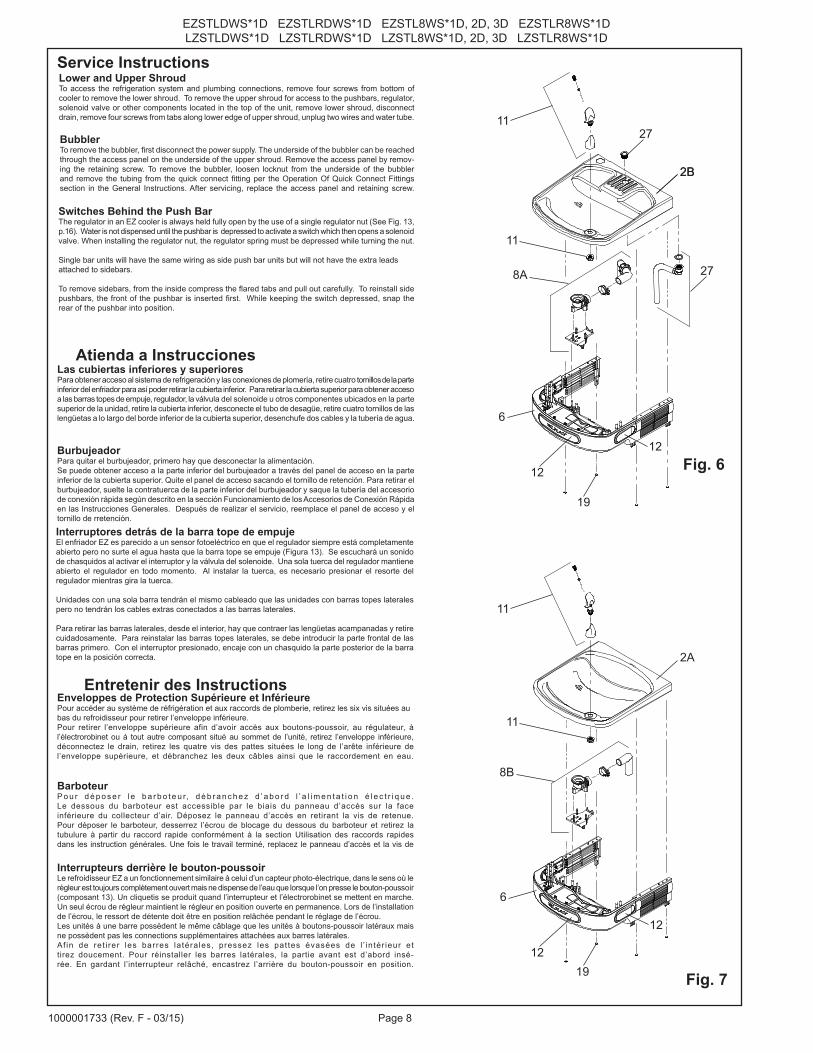
Lower and Upper ShroudTo access the refrigeration system and plumbing connections, remove four screws from bottom of cooler to remove the lower shroud. To remove the upper shroud for access to the pushbars, regulator, solenoid valve or other components located in the top of the unit, remove lower shroud, disconnect drain, remove four screws from tabs along lower edge of upper shroud, unplug two wires and water tube.
Las cubiertas inferiores y superioresPara obtener acceso al sistema de refrigeración y las conexiones de plomería, retire cuatro tornillos de la parte inferior del enfriador para así poder retirar la cubierta inferior. Para retirar la cubierta superior para obtener acceso a las barras topes de empuje, regulador, la válvula del solenoide u otros componentes ubicados en la parte superior de la unidad, retire la cubierta inferior, desconecte el tubo de desagüe, retire cuatro tornillos de las lengüetas a lo largo del borde inferior de la cubierta superior, desenchufe dos cables y la tubería de agua.
Interruptores detrás de la barra tope de empujeEl enfriador EZ es parecido a un sensor fotoeléctrico en que el regulador siempre está completamente abierto pero no surte el agua hasta que la barra tope se empuje (Figura 13). Se escuchará un sonido de chasquidos al activar el interruptor y la válvula del solenoide. Una sola tuerca del regulador mantiene abierto el regulador en todo momento. Al instalar la tuerca, es necesario presionar el resorte del regulador mientras gira la tuerca.
Unidades con una sola barra tendrán el mismo cableado que las unidades con barras topes laterales pero no tendrán los cables extras conectados a las barras laterales.
Para retirar las barras laterales, desde el interior, hay que contraer las lengüetas acampanadas y retire cuidadosamente. Para reinstalar las barras topes laterales, se debe introducir la parte frontal de las barras primero. Con el interruptor presionado, encaje con un chasquido la parte posterior de la barra tope en la posición correcta.
Enveloppes de Protection Supérieure et Inférieure Pour accéder au système de réfrigération et aux raccords de plomberie, retirez les six vis situées au bas du refroidisseur pour retirer l’enveloppe inférieure. Pour retirer l’enveloppe supérieure afin d’avoir accès aux boutons-poussoir, au régulateur, à l’électrorobinet ou à tout autre composant situé au sommet de l’unité, retirez l’enveloppe inférieure, déconnectez le drain, retirez les quatre vis des pattes situées le long de l’arête inférieure de l’enveloppe supérieure, et débranchez les deux câbles ainsi que le raccordement en eau.
Interrupteurs derrière le bouton-poussoir Le refroidisseur EZ a un fonctionnement similaire à celui d’un capteur photo-électrique, dans le sens où le régleur est toujours complètement ouvert mais ne dispense de l’eau que lorsque l’on presse le bouton-poussoir (composant 13). Un cliquetis se produit quand l’interrupteur et l’électrorobinet se mettent en marche. Un seul écrou de régleur maintient le régleur en position ouverte en permanence. Lors de l’installation de l’écrou, le ressort de détente doit être en position relâchée pendant le réglage de l’écrou. Les unités à une barre possèdent le même câblage que les unités à boutons-poussoir latéraux mais ne possèdent pas les connections supplémentaires attachées aux barres latérales. Af in de ret i rer les barres latérales, pressez les pattes évasées de l ’ intér ieur et tirez doucement. Pour réinstaller les barres latérales, la partie avant est d’abord insé-rée. En gardant l’interrupteur relâché, encastrez l’arrière du bouton-poussoir en position.
Service Instructions
Atienda a Instrucciones
Entretenir des Instructions
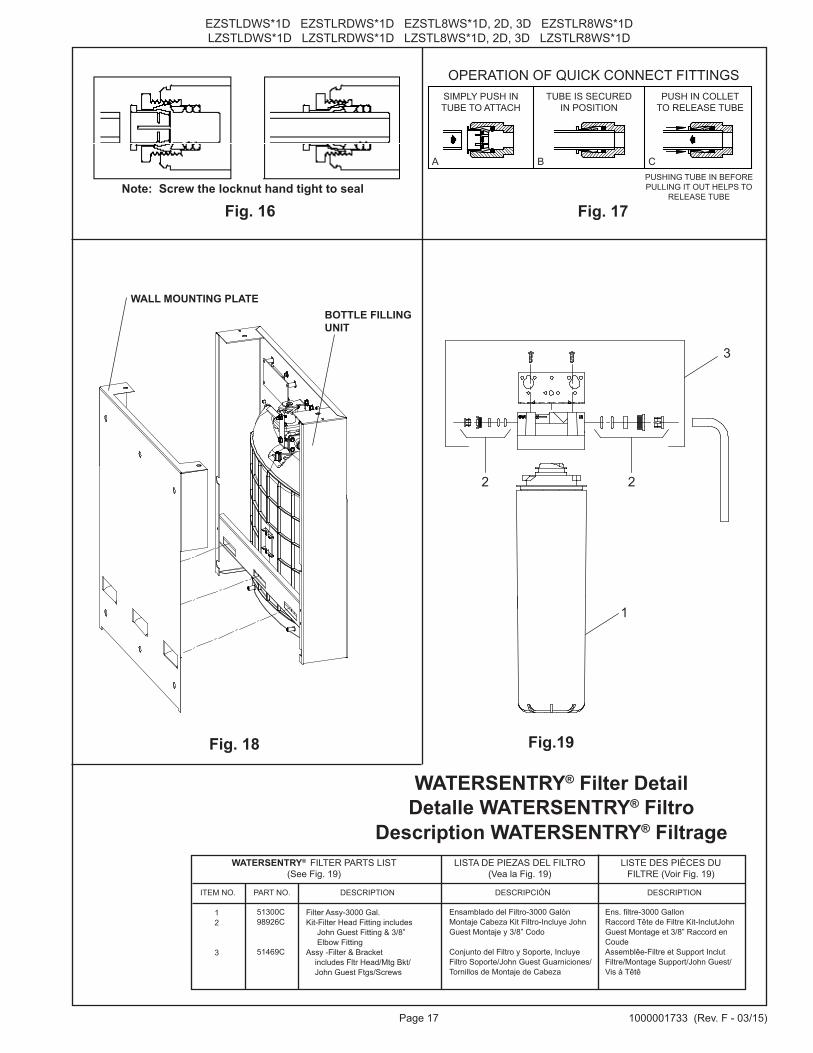
BubblerTo remove the bubbler, first disconnect the power supply. The underside of the bubbler can be reached through the access panel on the underside of the upper shroud. Remove the access panel by remov-ing the retaining screw. To remove the bubbler, loosen locknut from the underside of the bubbler and remove the tubing from the quick connect fitting per the Operation Of Quick Connect Fittings section in the General Instructions. After servicing, replace the access panel and retaining screw.
BarboteurP o u r d é p o s e r l e b a r b o t e u r, d é b r a n c h e z d ’ a b o r d l ’ a l i m e n t a t i o n é l e c t r i q u e .Le dessous du barboteur est accessible par le biais du panneau d’accès sur la face inférieure du collecteur d’air. Déposez le panneau d’accès en retirant la vis de retenue.Pour déposer le barboteur, desserrez l’écrou de blocage du dessous du barboteur et retirez la tubulure à partir du raccord rapide conformément à la section Utilisation des raccords rapides dans les instruction générales. Une fois le travail terminé, replacez le panneau d’accès et la vis de
BurbujeadorPara quitar el burbujeador, primero hay que desconectar la alimentación.Se puede obtener acceso a la parte inferior del burbujeador a través del panel de acceso en la parte inferior de la cubierta superior. Quite el panel de acceso sacando el tornillo de retención. Para retirar el burbujeador, suelte la contratuerca de la parte inferior del burbujeador y saque la tubería del accesorio de conexión rápida según descrito en la sección Funcionamiento de los Accesorios de Conexión Rápida en las Instrucciones Generales. Después de realizar el servicio, reemplace el panel de acceso y el tornillo de rretención.
11
2B
12
6
8A
19
12Fig. 6
Fig. 7
11
11
11
8B
12
6
1219
27
27
2B
2A
Switches Behind the Push BarThe regulator in an EZ cooler is always held fully open by the use of a single regulator nut (See Fig. 13, p.16). Water is not dispensed until the pushbar is depressed to activate a switch which then opens a solenoid valve. When installing the regulator nut, the regulator spring must be depressed while turning the nut.
Single bar units will have the same wiring as side push bar units but will not have the extra leads attached to sidebars.
To remove sidebars, from the inside compress the flared tabs and pull out carefully. To reinstall side pushbars, the front of the pushbar is inserted first. While keeping the switch depressed, snap the rear of the pushbar into position.
Page 9 1000001733 (Rev. F - 03/15)
EZSTLDWS*1D EZSTLRDWS*1D EZSTL8WS*1D, 2D, 3D EZSTLR8WS*1DLZSTLDWS*1D LZSTLRDWS*1D LZSTL8WS*1D, 2D, 3D LZSTLR8WS*1D
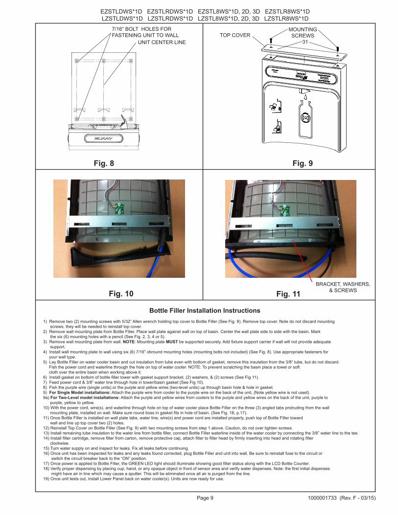
7/16” BOLT HOLES FOR FASTENING UNIT TO WALL
UNIT CENTER LINETOP COVER
MOUNTING SCREWS
Fig. 8 Fig. 9
31
Bottle Filler Installation Instructions1) Remove two (2) mounting screws with 5/32” Allen wrench holding top cover to Bottle Filler (See Fig. 9). Remove top cover. Note do not discard mounting
screws, they will be needed to reinstall top cover. 2) Remove wall mounting plate from Bottle Filler. Place wall plate against wall on top of basin. Center the wall plate side to side with the basin. Mark
the six (6) mounting holes with a pencil (See Fig. 2, 3, 4 or 5). 3) Remove wall mounting plate from wall. NOTE: Mounting plate MUST be supported securely. Add fixture support carrier if wall will not provide adequate
support. 4) Install wall mounting plate to wall using six (6) 7/16” obround mounting holes (mounting bolts not included) (See Fig. 8). Use appropriate fasteners for
your wall type. 5) Lay Bottle Filler on water cooler basin and cut insulation from tube even with bottom of gasket, remove this insulation from the 3/8” tube, but do not discard.
Fish the power cord and waterline through the hole on top of water cooler. NOTE: To prevent scratching the basin place a towel or soft cloth over the entire basin when working above it.
6) Install gasket on bottom of bottle filler tower with gasket support bracket, (2) washers, & (2) screws (See Fig 11). 7) Feed power cord & 3/8” water line through hole in tower/basin gasket (See Fig 10).8) Fish the purple wire (single units) or the purple and yellow wires (two-level units) up through basin hole & hole in gasket.9) For Single Model installations: Attach the purple wire from cooler to the purple wire on the back of the unit, (Note yellow wire is not used). 9a) For Two-Level model installations: Attach the purple and yellow wires from coolers to the purple and yellow wires on the back of the unit, purple to
purple, yellow to yellow. 10) With the power cord, wire(s), and waterline through hole on top of water cooler place Bottle Filler on the three (3) angled tabs protruding from the wall
mounting plate, installed on wall. Make sure round boss in gasket fits in hole of basin. (See Fig. 18, p.17). 11) Once Bottle Filler is installed on wall plate tabs, water line, wire(s) and power cord are installed properly, push top of Bottle Filler toward
wall and line up top cover two (2) holes. 12) Reinstall Top Cover on Bottle Filler (See Fig. 9) with two mounting screws from step 1 above. Caution, do not over tighten screws. 13) Install remaining tube insulation to the water line from bottle filler, connect Bottle Filler waterline inside of the water cooler by connecting the 3/8” water line to the tee. 14) Install filter cartridge, remove filter from carton, remove protective cap, attach filter to filter head by firmly inserting into head and rotating filter
clockwise.15) Turn water supply on and inspect for leaks. Fix all leaks before continuing. 16) Once unit has been inspected for leaks and any leaks found corrected, plug Bottle Filler and unit into wall. Be sure to reinstall fuse to the circuit or
switch the circuit breaker back to the “ON” position. 17) Once power is applied to Bottle Filler, the GREEN LED light should illuminate showing good filter status along with the LCD Bottle Counter. 18) Verify proper dispensing by placing cup, hand, or any opaque object in front of sensor area and verify water dispenses. Note: the first initial dispenses
might have air in line which may cause a sputter. This will be eliminated once all air is purged from the line. 19) Once unit tests out, install Lower Panel back on water cooler(s). Units are now ready for use.
Fig. 11Fig. 10BRACKET, WASHERS,
& SCREWS
EZSTLDWS*1D EZSTLRDWS*1D EZSTL8WS*1D, 2D, 3D EZSTLR8WS*1DLZSTLDWS*1D LZSTLRDWS*1D LZSTL8WS*1D, 2D, 3D LZSTLR8WS*1D
Page 101000001733 (Rev. F - 03/15)
VERIFY CONTROL BOARD SOFTWARE1) To verify the software program of the control board the unit will need to be shut down and restarted. The chiller (if present) does not need to be shut down and restarted.2) The units lower panel must be open to access the power cord and wall outlet.3) Shut down the unit by unplugging the power cord from the wall outlet. 4) Restart the unit by plugging the power cord back into the wall outlet.5) Upon start up, the bottle count display will show the software designation of BF11.
ACCESSING THE PROGRAMMING BUTTON1) To access the program button remove the top cover of the bottle- filler. Remove the two (2) screws holding top cover to bottle- filler with a 5/32” allen wrench. Remove top cover. Do not discard mounting screws, they will be needed to reinstall the top cove after programming operations are completed. The programming button is located at the top right side of the unit on the control board.
RESET THE FILTER MONITOR1) Instructions apply to filtered units only.2) Depress the program button for approximately 2 seconds until the display changes then release. The display will change and scroll through two messages: “RST FLTR” – Reset Filter Monitor “SETTINGS” – System Settings Sub Menu If the program button is not pushed again the display will scroll through the two messages above for three cycles and then default back to bottle count and be back in run mode.3) When the display changes to “RST FLTR”, depress the button again. The display will change to show “FLTR =”. Depress the button again and the display will show “FLTR =0”4) The Green LED should be illuminated indicating that the visual filter monitor has been reset.
SETTING RANGE OF THE IR SENSOR1) Depress the program button for approximately 2 seconds until the display changes then release. The display will change and scroll through two messages: “RST FLTR” – Reset Filter Status LED “SETTINGS” – System Settings Sub Menu If the program button is not pushed again the display will scroll through the two messages above for three cycles and then default back to bottle count and be back in run mode.2) When the display changes to “SETTINGS”, depress the button again. The display will change to show “RNG SET” - Range set for IR sensor. “UNIT TYP” - Type of unit (REFRIG or NON-RFRG) “FLT SIZE” - Select filter capacity “RST BCNT” - Reset bottle count3) When display shows “RNG SET” push program button once the display will show current value (can be 1 – 10) e.g. “RNG = 3”.4) Once display shows current value push the program button to scroll through value of 1 – 10. Select the desired range setting.5) Once range is selected allow approximately 4 seconds to pass and then the display will go back to bottle counter and be in run mode.6) Test bottle filler by placing bottle or hand in front of sensor to make sure water is dispensed.
SETTING UNIT TYPE1) Depress the program button for approximately 2 seconds until the display changes then release. The display will change and scroll through two messages: “RST FLTR” – Reset Filter Status LED “SETTINGS” – System Settings Sub Menu If the program button is not pushed again the display will scroll through the two messages above for three cycles and then default back to bottle count and be back in run mode.
Continued from below:2) When the display changes to “SETTINGS”, depress the button again. The display will change to show “RNG SET” - Range set for IR sensor. “UNIT TYP” - Type of unit (REFRIG or NON-RFRG) “FLT SIZE” - Select filter capacity “RST BCNT” - Reset bottle count3) When display shows “UNIT TYPE” push program button once the display will show current value. Can be REFRIG or NON-RFRG4) Push button once to change value. Once value is selected the display will show the new value. (Can be REFRIG or NON-RFRG) “REFRIG“ - stands for refrigerated product. In this setting the flow rate is estimated at 1.0 gallon per minute. “NON-RFRG“ - stands for nonrefrigerated product. In this setting the flow rate is estimated at 1.5 gallons per minute. Both “REFRIG“ and “NON-RFRG“ simulate 1 bottle equal to 20 oz.5) Allow approximately 4 seconds to pass and the display will return to bottle counter and be in run mode.
RESETTING BOTTLE COUNT1) Depress the program button for approximately 2 seconds until the display changes then release. The display will change and scroll through two messages: “RST FLTR” – Reset Filter Status LED “SETTINGS” – System Settings Sub Menu If the program button is not pushed again the display will scroll through the two messages above for three cycles and then default back to bottle count and be back in run mode.2) When the display changes to “SETTINGS”, depress the button again. The display will change to show: “RNG SET”- Range set for IR sensor. “UNIT TYP” - Type of unit (REFRIG or NON-RFRG) “FLT SIZE” - Select filter capacity “RST BCNT” - Reset bottle count If the button is not pushed again the display will scroll through the four messages above for three cycles and return to run mode.3) When display shows “RST BCNT” push program button once the display will show current value e.g. “0033183”.4) Once display shows current value push the program button once more to reset back to 0. The display will show BTLCT = 0 for approximately 2 seconds and then return to run mode showing 00000000 bottles.5) Testing the bottle counter: REFRIG units: Place bottle or hand in front of sensor for 9.4 seconds to see bottle counter count 00000001, (This is based on filling a 20 oz. bottle). NON-RFRG units: Place bottle or hand in front of sensor for 6.25 seconds to see bottle counter count 00000001, (This is based on filling a 20 oz bottle).
SETTING FILTER CAPACITY1) Depress the program button for approximately 2 seconds until the display changes then release. The display will change and scroll through two messages: “RST FLTR” – Reset Filter Status LED “SETTINGS” – System Settings Sub Menu If the program button is not pushed again the display will scroll through the two messages above for three cycles and then default back to bottle count and be back in run mode.2) When the display changes to “SETTINGS”, depress the button again. The display will change to show: “RNG SET“- Range set for IR sensor. “UNIT TYP“ - Type of unit (REFRIG or NON-RFRG) “FLT SIZE” - Select filter capacity “RST BCNT“ - Reset bottle count If the button is not pushed again the display will scroll through the four messages above for three cycles and return to run mode.3) When display shows “FLT SIZE” push program button once. The display will show current value. Can be 3000GAL or 6000GAL.4) Push program button again to display the desired “FLT SIZE”. 5) Allow approximately 4 seconds to pass and the display will return to bottle counter and be in run mode.
BF11 PROGRAMSETTING THE CONTROL BOARD
Page 11 1000001733 (Rev. F - 03/15)
EZSTLDWS*1D EZSTLRDWS*1D EZSTL8WS*1D, 2D, 3D EZSTLR8WS*1DLZSTLDWS*1D LZSTLRDWS*1D LZSTL8WS*1D, 2D, 3D LZSTLR8WS*1D
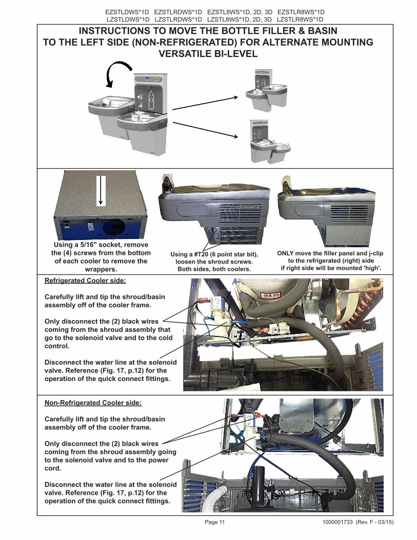
INSTRUCTIONS TO MOVE THE BOTTLE FILLER & BASIN TO THE LEFT SIDE (NON-REFRIGERATED) FOR ALTERNATE MOUNTING
VERSATILE BI-LEVEL
Using a 5/16" socket, remove the (4) screws from the bottom of each cooler to remove the
wrappers.Refrigerated Cooler side:
Carefully lift and tip the shroud/basin assembly off of the cooler frame.
Only disconnect the (2) black wires coming from the shroud assembly that go to the solenoid valve and to the cold control.
Disconnect the water line at the solenoid valve. Reference (Fig. 17, p.12) for the operation of the quick connect fittings.
Non-Refrigerated Cooler side:
Carefully lift and tip the shroud/basin assembly off of the cooler frame.
Only disconnect the (2) black wires coming from the shroud assembly going to the solenoid valve and to the power cord.
Disconnect the water line at the solenoid valve. Reference (Fig. 17, p.12) for the operation of the quick connect fittings.
Using a #T20 (6 point star bit), loosen the shroud screws. Both sides, both coolers.
ONLY move the filler panel and j-clip to the refrigerated (right) side
if right side will be mounted 'high'.
EZSTLDWS*1D EZSTLRDWS*1D EZSTL8WS*1D, 2D, 3D EZSTLR8WS*1DLZSTLDWS*1D LZSTLRDWS*1D LZSTL8WS*1D, 2D, 3D LZSTLR8WS*1D
Page 121000001733 (Rev. F - 03/15)
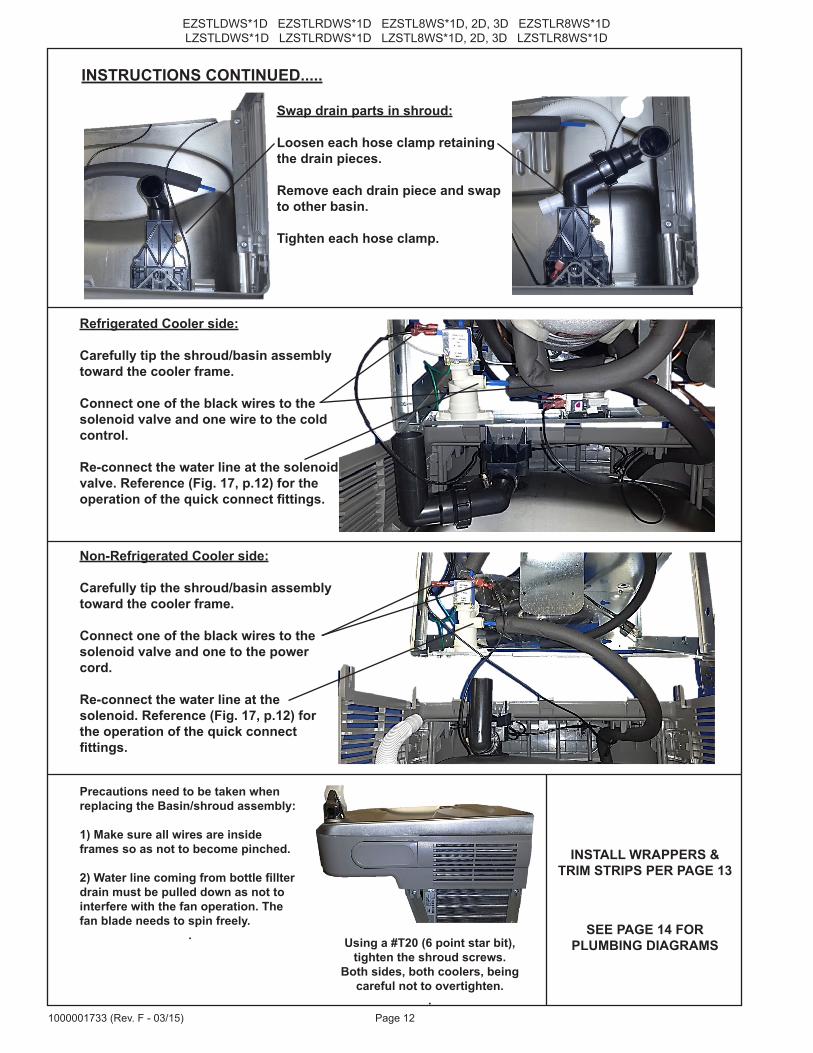
INSTRUCTIONS CONTINUED.....
Swap drain parts in shroud:
Loosen each hose clamp retainingthe drain pieces.
Remove each drain piece and swapto other basin.
Tighten each hose clamp.
Refrigerated Cooler side:
Carefully tip the shroud/basin assembly toward the cooler frame.
Connect one of the black wires to the solenoid valve and one wire to the cold control.
Re-connect the water line at the solenoid valve. Reference (Fig. 17, p.12) for the operation of the quick connect fittings.
Non-Refrigerated Cooler side:
Carefully tip the shroud/basin assembly toward the cooler frame.
Connect one of the black wires to the solenoid valve and one to the power cord.
Re-connect the water line at the solenoid. Reference (Fig. 17, p.12) for the operation of the quick connect fittings.
Using a #T20 (6 point star bit), tighten the shroud screws.
Both sides, both coolers, being careful not to overtighten.
.
SEE PAGE 14 FORPLUMBING DIAGRAMS
Precautions need to be taken when replacing the Basin/shroud assembly:
1) Make sure all wires are inside frames so as not to become pinched.
2) Water line coming from bottle fillter drain must be pulled down as not to interfere with the fan operation. The fan blade needs to spin freely.
.
INSTALL WRAPPERS & TRIM STRIPS PER PAGE 13
Page 13 1000001733 (Rev. F - 03/15)
EZSTLDWS*1D EZSTLRDWS*1D EZSTL8WS*1D, 2D, 3D EZSTLR8WS*1DLZSTLDWS*1D LZSTLRDWS*1D LZSTL8WS*1D, 2D, 3D LZSTLR8WS*1D
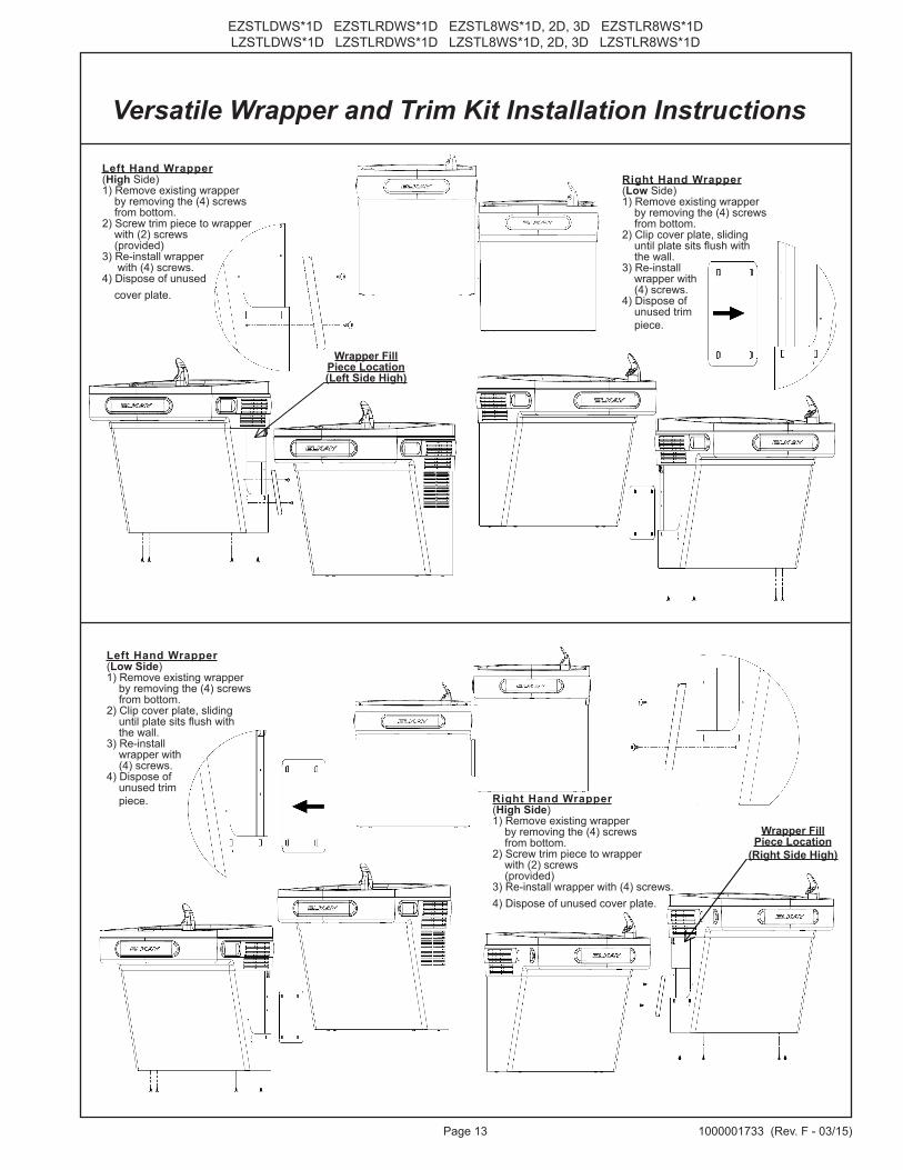
Versatile Wrapper and Trim Kit Installation Instructions
Left Hand Wrapper(Low Side)1) Remove existing wrapper by removing the (4) screws from bottom.2) Clip cover plate, sliding until plate sits flush with the wall.3) Re-install wrapper with (4) screws.4) Dispose of unused trim piece. Right Hand Wrapper
(High Side)1) Remove existing wrapper by removing the (4) screws from bottom.2) Screw trim piece to wrapper with (2) screws (provided) 3) Re-install wrapper with (4) screws.4) Dispose of unused cover plate.
Right Hand Wrapper(Low Side)1) Remove existing wrapper by removing the (4) screws from bottom.2) Clip cover plate, sliding until plate sits flush with the wall.3) Re-install wrapper with (4) screws.4) Dispose of unused trim piece.
Left Hand Wrapper(High Side)1) Remove existing wrapper by removing the (4) screws from bottom.2) Screw trim piece to wrapper with (2) screws (provided) 3) Re-install wrapper with (4) screws.4) Dispose of unused cover plate.
Wrapper FillPiece Location(Left Side High)
Wrapper FillPiece Location
(Right Side High)
EZSTLDWS*1D EZSTLRDWS*1D EZSTL8WS*1D, 2D, 3D EZSTLR8WS*1DLZSTLDWS*1D LZSTLRDWS*1D LZSTL8WS*1D, 2D, 3D LZSTLR8WS*1D
Page 141000001733 (Rev. F - 03/15)
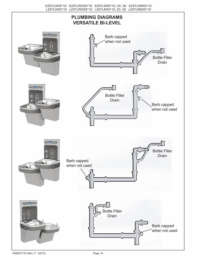
PLUMBING DIAGRAMSVERSATILE BI-LEVEL
Barb cappedwhen not used
Barb cappedwhen not used
Barb cappedwhen not used
Barb cappedwhen not used
Bottle FillerDrain
Bottle FillerDrain
Bottle FillerDrain
Bottle FillerDrain
Page 15 1000001733 (Rev. F - 03/15)
EZSTLDWS*1D EZSTLRDWS*1D EZSTL8WS*1D, 2D, 3D EZSTLR8WS*1DLZSTLDWS*1D LZSTLRDWS*1D LZSTL8WS*1D, 2D, 3D LZSTLR8WS*1D
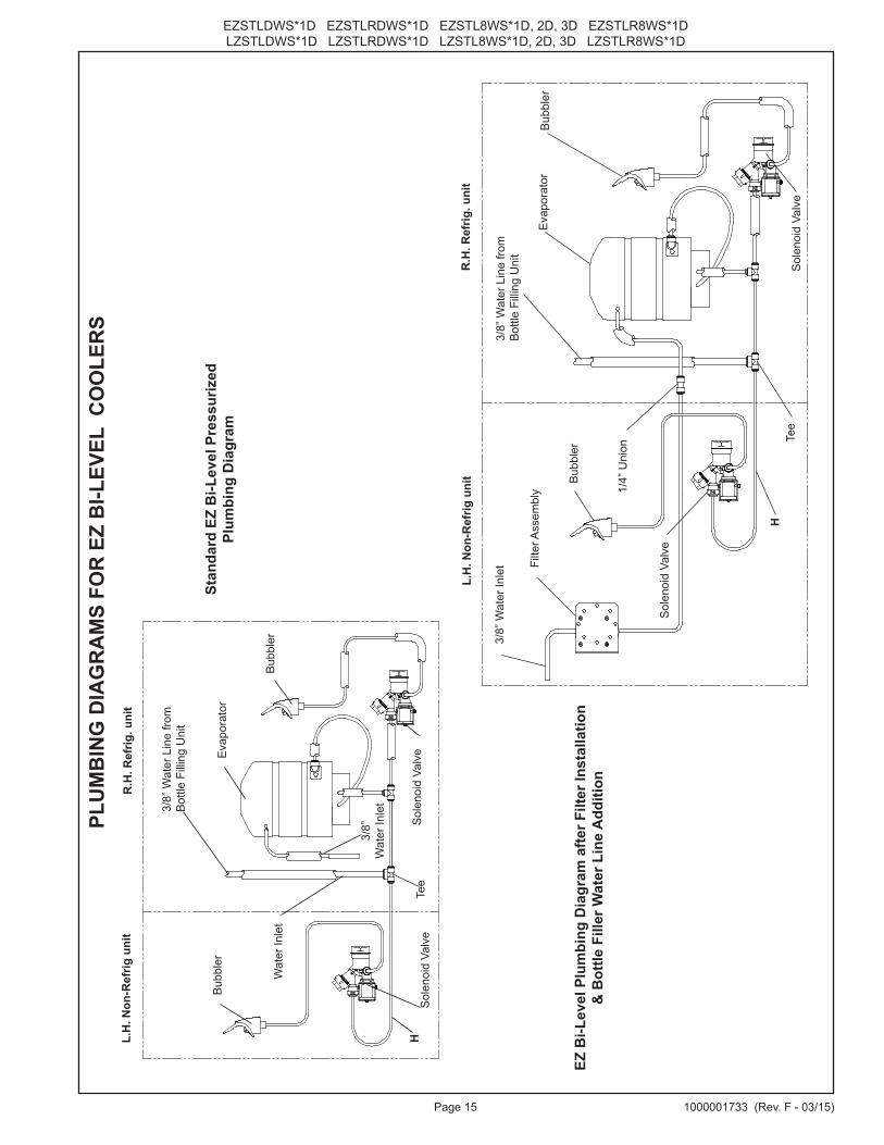
Stan
dard
EZ
Bi-L
evel
Pre
ssur
ized
Pl
umbi
ng D
iagr
am
EZ B
i-Lev
el P
lum
bing
Dia
gram
afte
r Filt
er In
stal
latio
n &
Bot
tle F
iller
Wat
er L
ine
Add
ition
R.H
. Ref
rig. u
nit
L.H
. Non
-Ref
rig u
nit Bub
bler
Bub
bler
Eva
pora
tor
3/8”
Wat
er In
let
Tee
3/8”
Wat
er L
ine
from
B
ottle
Fill
ing
Uni
t
H
Filte
r Ass
embl
y 1/4”
Uni
on
Sol
enoi
d Va
lve
Sol
enoi
d Va
lve
PLU
MB
ING
DIA
GR
AM
S FO
R E
Z B
I-LEV
EL C
OO
LER
SR
.H. R
efrig
. uni
tL.
H. N
on-R
efrig
uni
t
Eva
pora
tor
Bub
bler
Wat
er In
let
Bub
bler
HS
olen
oid
Valv
eS
olen
oid
Valv
e
3/8”
Wat
er In
let3/8”
Wat
er L
ine
from
B
ottle
Fill
ing
Uni
t
Tee
EZSTLDWS*1D EZSTLRDWS*1D EZSTL8WS*1D, 2D, 3D EZSTLR8WS*1DLZSTLDWS*1D LZSTLRDWS*1D LZSTL8WS*1D, 2D, 3D LZSTLR8WS*1D
Page 161000001733 (Rev. F - 03/15)
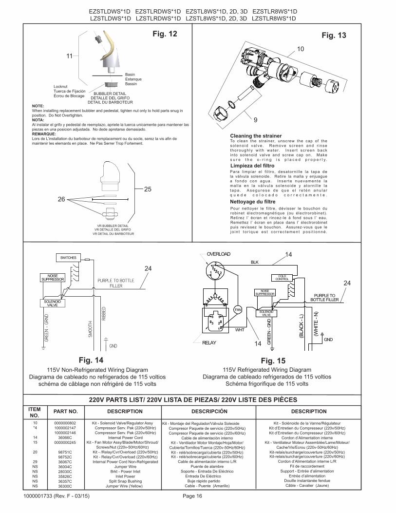
1
C
SFAN
1
WHT
5
2
6
3
M
3
2
GND
BLK
RELAY
OVERLOAD
COLDCONTROL
SOLENOIDVALVE
GRE
EN -
GND
NOISESUPPRESSOR PURPLE TO
BOTTLE FILLER(B
LAC
K - L
)
(WHI
TE -
N)
BUBBLER DETAILDETALLE DEL GRIFO
DETAIL DU BARBOTEURNOTE:When installing replacement bubbler and pedestal, tighten nut only to hold parts snug in position. Do Not Overtighten.NOTA:Al instalar el grifo y pedestal de reemplazo, apriete la tuerca unicamente para mantener las piezas en una posicion adjustada. No dede apretarse demasiado.REMARQUE:Lors de L’installation du barboteur de remplacement ou du socle, serez la vis afin de maintenir les elemants en place. Ne Pas Serrer Trop Fortement.
BasinEstanqueBassin
11
Fig. 12
9
Cleaning the strainerTo clean the strainer, unscrew the cap of theso leno id va lve . Remove sc reen and r insethorough ly w i th wa te r. Inser t sc reen backinto solenoid valve and screw cap on. Makes u r e t h e o - r i n g i s p l a c e d p r o p e r l y .
Limpieza del filtroPara l impiar e l f i l t ro, desatorni l le la tapa dela válvula solenoide. Retire la malla y enjuague a fondo con agua . Inser te nuevamente lamal la en la vá lvu la so leno ide y a torn i l le lat a p a . A s e g u r e s e d e q u e e l r e t é n a n u l a r q u e d e c o l o c a d o c o r r e c t a m e n t e .
Pour nettoyer le fi l tre, dévisser le bouchon durobinet électromagnétique (ou électrorobinet).Retirez l’ écran et rincez-le á fond sous l’ eau.Remettez l’ écran en place dans l’ électrorobinetpuis revissez le bouchon. Assurez-vous que le j o i n t t o r i q u e e s t c o r r e c t e m e n t p o s i t i o n n é .
Nettoyage du filtre
Fig. 13
Fig. 14
14
14
10
Fig. 15
PURPLE TO BOTTLEFILLER
GREE
N -
GRND
GND
SOLENOIDVALVE
NOISESUPPRESSOR
SWITCHES
RIBB
ED
SMOO
TH
115V Non-Refrigerated Wiring DiagramDiagrama de cableado no refrigerados de 115 voltios
schéma de câblage non réfrigéré de 115 volts
115V Refrigerated Wiring DiagramDiagrama de cableado refrigerados de 115 voltios
Schéma frigorifique de 115 volts
LocknutTuerca de FijaciónÉcrou de Blocage
24
24
10*4
1415
20
29NSNSNSNSNS
000000080210000021471000002146
36066C0000000245
98751C98752C36067C36004C28030C35826C36357C36300C
Kit - Solenoid Valve/Regulator AssyCompressor Serv. Pak (220v/50Hz)Compressor Serv. Pak (220v/60Hz)
Internal Power CordKit - Fan Motor Assy/Blade/Motor/Shroud/
Screws/Nut (220v-50Hz/60Hz)Kit - /Relay/Cvr/Overload (220v/50Hz)Kit - Relay/Cvr/Overload (220v/60Hz)Internal Power Cord Non-Refrigerated
Jumper WireBrkt - Power Inlet
Inlet PowerSplit Snap Bushing
Jumper Wire (Yellow)
Kit - Montaje del Regulador/Válvula SoleoideCompresor Paquete de servicio (220v/50Hz)Compresor Paquete de servicio (220v/60Hz)
Cable de alimentación internoKit - Ventilador Motor Montaje/Hoja/Motor/
Cubierta/Tornillos/Tuerca (220v-50Hz/60Hz)Kit - relé/sobrecarga/cubierta (220v/50Hz)Kit - relé/sobrecarga/cubierta (220v/60Hz)
Cable de alimentación interno L/RPuente de alambre
Soporte - Entrada De Eléctrico Entrada De Eléctrico Buje rápido partido
Cable - Puente (Amarillo)
220V PARTS LIST/ 220V LISTA DE PIEZAS/ 220V LISTE DES PIÈCES
Kit - Solénoide de la Vanne/RégulateurKit d’Entretien du Compresseur (220v/50Hz)Kit d’Entretien du Compresseur (220v/60Hz)
Cordon d’Alimentation interneKit - Ventilateur Moteur Assemblée/Lame/Moteur/
Cache/Vis/Ecrou (220v-50Hz/60Hz)Kit-relais/surcharge/couverture (220v/50Hz)Kit-relais/surcharge/couverture (220v/60Hz)
Cordon d’Alimentation interne L/RFil de raccordement
Support - Entrée d’alimentationEntrée d’alimentation
Douille instantanée fendueCâble - Cavalier (Jaune)
ITEM NO.
PART NO. DESCRIPTION DESCRIPCIÓN DESCRIPTION
VR BUBBLER DETAILVR DETALLE DEL GRIFO
VR DETAIL DU BARBOTEUR
2526
Page 17 1000001733 (Rev. F - 03/15)
EZSTLDWS*1D EZSTLRDWS*1D EZSTL8WS*1D, 2D, 3D EZSTLR8WS*1DLZSTLDWS*1D LZSTLRDWS*1D LZSTL8WS*1D, 2D, 3D LZSTLR8WS*1D
B CA
SIMPLY PUSH INTUBE TO ATTACH
TUBE IS SECUREDIN POSITION
PUSH IN COLLETTO RELEASE TUBE
OPERATION OF QUICK CONNECT FITTINGS
PUSHING TUBE IN BEFOREPULLING IT OUT HELPS TO
RELEASE TUBE
OPERATION OF QUICK CONNECT FITTINGSSIMPLY PUSH INTUBE TO ATTACH
TUBE IS SECURED IN POSITION
PUSH IN COLLETTO RELEASE TUBE
PUSHING TUBE IN BEFORE PULLING IT OUT HELPS TO
RELEASE TUBE
A B C
Fig.19
DESCRIPTION
12
3
ITEM NO. PART NO.
51300C98926C
51469C
Filter Assy-3000 Gal.Kit-Filter Head Fitting includes John Guest Fitting & 3/8” Elbow FittingAssy -Filter & Bracket includes Fltr Head/Mtg Bkt/ John Guest Ftgs/Screws
DESCRIPCIÓN DESCRIPTION
Ensamblado del Filtro-3000 GalónMontaje Cabeza Kit Filtro-Incluye John Guest Montaje y 3/8” Codo
Conjunto del Filtro y Soporte, Incluye Filtro Soporte/John Guest Guarniciones/Tornillos de Montaje de Cabeza
Ens. filtre-3000 GallonRaccord Tête de Filtre Kit-InclutJohn Guest Montage et 3/8” Raccord en CoudeAssemblêe-Filtre et Support Inclut Filtre/Montage Support/John Guest/Vis à Têtê
WATERSENTRY® FILTER PARTS LIST(See Fig. 19)
LISTA DE PIEZAS DEL FILTRO (Vea la Fig. 19)
LISTE DES PIÈCES DU FILTRE (Voir Fig. 19)
WATERSENTRY® Filter DetailDetalle WATERSENTRY® Filtro
Description WATERSENTRY® Filtrage
3
2
1
2
BOTTLE FILLINGUNIT
WALL MOUNTING PLATE
Fig. 18
Fig. 16 Note: Screw the locknut hand tight to seal
Fig. 17
EZSTLDWS*1D EZSTLRDWS*1D EZSTL8WS*1D, 2D, 3D EZSTLR8WS*1DLZSTLDWS*1D LZSTLRDWS*1D LZSTL8WS*1D, 2D, 3D LZSTLR8WS*1D
Page 181000001733 (Rev. F - 03/15)
ITEM NO.
Support de SuspensionBasin - Inox
Basin - Inox (BF)Barre Anti-Panique Câblage Avant/Côté
Kit d’Entretien du Compresseur Tubes - Polyéthylène (Couper à la Longueur)
Enveloppe de Protection - Supérieure (Face LaterelPoussoir) Déshydrateur
Kit - Remplacement de Drain (EZTL)/Support/Tube/Raccord de Tube/Bride Pour Tuyau
Kit - Remplacement de Drain (EZTLD)/Support/Tube/Raccord de Tube/Bride Pour Tuyau
Kit De Rechange De Bouchon/Ecran/Joint ToriqueKit - Solénoide de la Vanne/Régulateur
Kit - Flexi Barboteur/Oring/NoixKit - Barre de Poussée (Avant/Côté) EZSTL
Kit - Barre de Poussée (Avant) EZSTLKit - Contrôle de Refroidissement/Vis
Kit - Câblage Interne/Câble d’Alimentation/Noir etFils de Raccordement Blanc
Kit - Ventilateur Moteur Assemblée/Lame/Moteur/Cache/Vis/Ecrou
Kit - Condenseur/SéchoirKit - Montage du Compresseur materiel/Joint
d’étanchéité/Clip/GoujonKit - Echangeur Thermique/Déshydrateur
Kit - De Visserie (EZ)Kit - Relais/Surcharge/Relais CoiffeAssemblée de L’évaporateur en Kit
Kit - Tee 1/4” x 1/4” x 3/8” (Pack de 3)Kit - 75583C Elbow 5/16” x 1/4” (Pack de 3)
Câble - Cavalier (Pourpre)Kit - Vandal barboteur résistant
Kit - VR Nipple W / Joints (moins barboteur)Kit - de Remplissage de Bouteille de Vidange
Gaspiller TL (R) d’Assemblée de LigneCordon d’Alimentation L/R
Kit - 70682C 1/4” Tee (Pack de 3)Enveloppe extérieure kit-inox (R)Kit-gris de Cape extérieure (R)
Acier inoxydable-kit Cape extérieure sans persiennes (L)Enveloppe extérieure kit-gris sans persiennes (L)
Câble - Cavalier (Jaune)Couvre-joint - Inox
Couvre-joint - Gris clair
28401C55001109
000000133736216C36322C56092C56229C66703C98900C
97969C
98169C98466C92715C98734C
100000160098773C98774C
98775C
98776C98777C
98778C98898C
000000023898724C
10000020621000001602
36299C97446C
100000179110000018121000002055
35980C10000019941000000888100000094410000007581000000759
36300C28021C28020C
Hanger BracketBasin - Stainless Steel
Basin - Stainless Steel (BF)Wiring - Front/Side Push BarCompr - Service Pak 115VTube - Poly (Cut To Length)
Assy - Shroud - Upper (Front Side Push)Drier
Kit - Drain Replacement EZTL8(Brkt, Tube, Ftg, Clamp)
Kit - Drain Replacement EZTLD (BF)(Brkt, Tube, Ftg, Clamp)
Kit - Replacement Cap/Screen/O-Ring Kit - Solenoid Valve/Regulator Assy
Kit - Flexi Bubbler/“O”-Ring/NutKit - Pushbar (Front/Side) EZSTL
Kit - Pushbar (Front) EZTLKit - Cold Control/Screws
Kit - Internal Wiring/Pwr Cord/Blackand White Jumper Wires
Kit - Fan Motor Assy/Blade/Mtr/Shroud/Screws/Nut
Kit - Condenser/Drier Kit- Compr Mtg Hdwe/Grommets/
Clips/StudsKit - Heatx/Drier
Kit - Hardware (EZ) Kit - Relay/Overload/CoverKit - Evaporator Assembly
Kit - Tee 1/4” x 1/4” x 3/8” (3 Pack)Kit - 75583C Elbow 5/16” x 1/4” (3 Pack)
Jumper Wire (Purple)Kit - VR Bubbler
Kit - VR Nipple W/Gasket (less Bubbler)Kit - Bottle Filler Drain
Wasteline Drain AssyPower Cord Non-RefrigeratedKit - 70682C 1/4” Tee (3 Pack)
Kit - EZTL Wrapper/Serv Label - Stainless (R)Kit - EZTL Wrapper/Serv Label - Light Grey (R)Kit - EZTLD Wrapper/Serv Label - Stainless (L)Kit - EZTLD Wrapper/Serv Label - Light Grey (L)
Jumper Wire (Yellow)Wrapper - Filler StainlessWrapper - Filler Light Grey
PART NO. DESCRIPTION DESCRIPCIÓN DESCRIPTION
12A2B3*4567
8A
8B
9101112
1314
15
1617
18192021222324252627282930NS
NS
NSNS
Soporte ColganteEstanque - Acero Inoxidable
Estanque - Acero Inoxidable (BF)Barra de Empuje de Cableado-Frontal/Lateral
Compresor Paquete de Servicio 115V Tubería de Polietileno (Corte a la Longitud)Cubierta - Superior (Frontal Lateral Presión)
SecadorKit - Reemplazo de Drenaje (EZTL8)/Soporte/Tubo/
Guarnición de Tubo/AbrazaderaKit - Reemplazo de Drenaje (EZTLD)/Soporte/Tubo/
Guarnición de Tubo/AbrazaderaKit del Reemplazo Tapa/Malla/Reten Anular
Kit - Montaje del Regulador/Válvula SolenoideKit - Flexi Borboteador/Oring/TeurcaKit - Manillar (Frontal/Lateral) EZSTL
Kit - Manillar (Frontal) EZSTLKit - Control del Enfriamiento/Tornillo
Kit - Cableado Interno/Cable/Negro Y Blanco Puente
Kit - Ventilador Motor Montaje/Hoja/Motor/Cubierta/Tornillos/Tuerca
Kit - Condensador/SecadorKit - Matériel de Montaje Compresor/Ojal/
Pinza/TaqueteKit - Intercambiador Térmico/Secador
Kit - Juego de Accesorios (EZ) Kit - Relé/Sobrecarga/Cubierta
Montaje del Kit-EvaporadorKit - Tee 1/4” x 1/4” x 3/8” (Paquete de 3)
Kit - 75583C Elbow 5/16” x 1/4” (Paquete de 3)Cable - Puente (Púrpura)
Kit - Vandal Resistente peleleKit - VR Nipple W / Juntas (menos Pelele)Kit - de Drenaje de Llenada de la Botella
Malgaste la Asamblea de la Linea EZTL(R)Cable eléctrico L/R
Kit - 70682C 1/4” Tee (paquete de 3)Kit - envoltura de acero inoxidable (R)
Kit de luz gris envoltura (R) Envoltura exterior kit-acero inoxidable sin rejillas (L)
Gris luz kit envoltura exterior sin rejillas (L)Cable - Puente (Amarillo)
Envoltura Llenador Acero inoxidableEnvoltura Llenador Gris claro
PRINTED IN U.S.A.IMPRESO EN LOS E.E.U.U.IMPRIMÉ AUX É.-U.
FOR PARTS, CONTACT YOUR LOCAL DISTRIBUTOR OR CALL 1.800.834.4816PARA PIEZAS, CONTACTE A SU DISTRIBUIDOR LOCAL O LLAME AL 1.800.834.4816
POUR OBTENIR DES PIÈCES, CONTACTEZ VOTRE DISTRIBUTEUR LOCAL OU COMPOSEZ LE 1.800.834.4816
ELKAY MANUFACTURING COMPANY • 2222 CAMDEN COURT • OAK BROOK, IL 60523 • 630.574.8484
REPAIR SERVICE INFORMATION TOLL FREE NUMBER 1.800.260.6640 NÚMERO GRATIS DE SERVICIO 1.800.260.6640
INFORMATIONS POUR LE SERVICE PAR NUMERO SANS FRAIS 1.800.260.6640
*COMPREND RELAIS ET SURCHARGE. SI SOUS GARANTIE, REM-PLACEZ AVEC LE MÊME SURPRESSEUR QUE CELUI UTILISÉ ORIGINALEMENT.NOTE: Toute correspondance au sujet des refroidisseurs d’eau courante ou toute commande de pièce de rechange DOIT inclure le numéro de modèle et le numéro de série du refroidisseur ainsi que le nom et le numéro de pièce à remplacer.
*INCLUDES RELAY & OVERLOAD. IF UNDER WAR-RANTY, REPLACE WITH SAME COMPRESSOR USED IN ORIGINAL ASSEMBLY. NOTE: All correspondence pertaining to any of the above water coolers or orders for repair parts MUST include Model No. and Serial No. of cooler, name and part number of replacement part.
*INCLUYE RELÉ Y SOBRECARGA. SI ESTÁ BAJO GARANTÍA, REEMPLACE CON EL MISMO COMPRESOR USADO EN EL ENSAMBLADO INICIAL.NOTA: Toda la correspondencia relacionada con el enfriador de agua anterior o con una orden de reparación piezas DEBERÁ incluir el número de modelo y número de serie del enfriador, el nombre y número de pieza de la pieza de repuesto.
BOTTLE FILLER REPLACEMENT PART KITS
NSNSNSNSNS3132NSNSNS
ITEM NO.
PART NO. DESCRIPTION DESCRIPCIÓN DESCRIPTION
98543C98544C98545C98632C98546C98547C98549C98551C98552C
1000001813
Kit - Electrical PackageKit - IR SensorKit - BF Solenoid Valve Replacement 115VKit - BF Solenoid Valve Replacement 230VKit - Aerator ReplacementKit - Top Cover ReplacementKit - Hardware & Waterway PartsKit - Filter Mounting CoverKit - Retro Filter MountingKit - Tower/Basin Gasket
Paquete Kit - EléctricoSensor Kit - IRReemplazo de la Válvula de Solenoide Kit 115VReemplazo de la Válvula de Solenoide Kit 230VReemplazo Kit - AireadorKit - Tapa Cubierta Reemplazo Piezas del Kit - De Hardware y Por Vía NavegableCubierta del Filtro de Kit - De MontajeMontaje de Filtro Kit - RetroKit - Torre/Cuenca Junta
Forfait Kit - ElectriquesoKit - Rcepteur IRRemplacement de la Valve Solénoïde - Kit 115VRemplacement de la Valve Solénoïde - Kit 230VRemplacement du Kit - Aérateur Remplacement du Kit - Top Couvercle Pièces Kit - Matériel et Voie NavigableCouvercle de Filtre - Kit MontageMontage de Retro - Kit FiltreKit - Tour/Collecteur