Embed Size (px)
Citation preview

SCREEN ROOM
Installation andOperating Instructions
For Use with SunSetter AwningsModels 900, 900XT, 1000, 1000XT
For technical support visit us at www.sunsetter.com/ownerscorner, email us [email protected] or call 800-670-7071, fax 877-224-4944.

Congratulations on the purchase of your SunSetter Screen Room! We know you will enjoy many additionalhours on your deck or patio, day and night, bug free! Before you begin installation, take a moment to familiarizeyourself with the Screen Room Installation and Operating Instructions. Please check to ensure all of the parts listed onPage 2 have been included with your order and that you have the proper size Screen Room for your awning.
INSTALLATION OF YOUR SCREEN ROOM:
Note: It is important to follow the instructions very closely when installing your Screen Room awning. Leftand Right references are as you are facing the house.
When installing your Screen Room you will be mounting approximately 2" below your awning. The Screen Room ismanufactured with additional material on both side panels and the top panel to accommodate varying mountingheights. The Screen Room has a maximum mounting height of 9’6". You will be given instructions to gather theexcess fabric if you are mounting below this height. This process will only be required once during the initialinstallation. You will find installation instructions for mounting your Screen Room on wood, vinyl and aluminum sidingand for masonry or brick walls.
OPERATION OF YOUR SCREEN ROOM:
Your SunSetter Screen Room, once installed, allows access through the door in the front panel, or side wall zipperson both the left and right side panels to suit your deck or patio design. The awning will always need to be extended oropened completely and the rafters locked, but the arms may be placed in either the diagonal or vertical position whenusing your Screen Room. Refer to your Screen Room Installation and Operating Instructions for detailed information.
Note: It is best to follow the care and maintenance suggestions on page 14 of your Instructions for propercare and maintenance and removal instructions for your Screen Room.
CUSTOMER SUPPORT:
Our technical experts are available 24 hours daily via email at [email protected] or call us at 800-670-7071should you require assistance. We also invite you to visit the Owner’s Corner at www.sunsetter.com/ownerscorner foradditional information on your awning and other products.
We know that you will be delighted with your SunSetter Screen Room and will experience many years ofadded enjoyment on your deck or patio.

Parts Supplied ........................................................................................................................ Page 2
General Installation Procedures ........................................................................................... Page 3
Positioning Mounting Rail on the House.............................................................................Page 4
Attaching Screen Room to the House .................................................................................. Page 6
Securing Screen Room to Deck/Patio ................................................................................. Page 10
Final Assembly Procedures ................................................................................................... Page 12
Opening or Closing Screen Room Doorway ....................................................................... Page 13
Removal ................................................................................................................................... Page 14
Storage .................................................................................................................................... Page 14
Trouble Shooting .................................................................................................................... Page 14
Table of Contents
Page 2
1 1/2” Mounting Rail Screw
Zipper Stop
Mounting Rail
16” and 20” Bungee 5 1/4” Bungee with Ball (Qty. 4)
Foam Weatherstrip
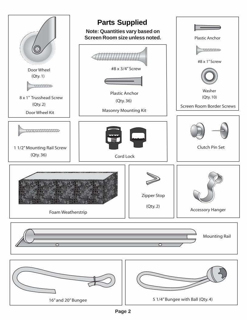
Note: Quantities vary based on screen room size unless noted.
#8 x 3/4” Screw
Plastic Anchor
(Qty. 36)
(Qty. 2)
(Qty. 36)
Plastic Anchor
#8 x 1” Screw
Washer
(Qty. 10)
Door Wheel
8 x 1” Trusshead Screw
(Qty. 2)
Clutch Pin Set
Accessory Hanger
Cord Lock
(Qty. 1)
Door Wheel Kit Masonry Mounting KitScreen Room Border Screws
Parts SuppliedNote: Quantities vary based onScreen Room size unless noted.
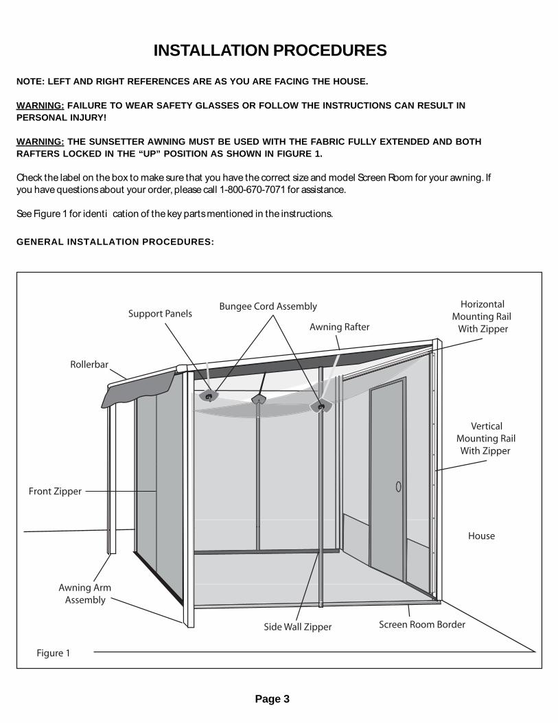
INSTALLATION PROCEDURESNOTE: LEFT AND RIGHT REFERENCES ARE AS YOU ARE FACING THE HOUSE.
WARNING: FAILURE TO WEAR SAFETY GLASSES OR FOLLOW THE INSTRUCTIONS CAN RESULT INPERSONAL INJURY!
WARNING: THE SUNSETTER AWNING MUST BE USED WITH THE FABRIC FULLY EXTENDED AND BOTHRAFTERS LOCKED IN THE “UP” POSITION AS SHOWN IN FIGURE 1.
Check the label on the box to make sure that you have the correct size and model Screen Room for your awning. Ifyou have questionsabout your order, please call 1-800-670-7071 for assistance.
See Figure 1 for identi�cation of the key parts mentioned in the instructions.
GENERAL INSTALLATION PROCEDURES:
Page 3
vvvv
vvvv
vvvv
vvvv
vvvv
vvvv
vvvv
vvvv
vvvv
vvvv
vvvv
vvvv
vvvv
vvvv
vvvv
vvvv
vvvv
vvvv
vvvv
vvvv
vvvv
vvvv
vvvv
vvvv
vvvv
vvvv
vvvv
vvvv
vvvv
vvvv
vvvv
vvvv
vvvv
vvvv
vvvv
vvvv
vvvv
vvvv
vvvv
vvvv
vvvv
vvvv
vvvv
vvvv
vvvv
vvvv
vvvv
vvvv
vvvv
vvvv
vvvv
vvvv
vvvv
vvvv
vvvv
vvvv
vvvv
vvvv
vvvv
vvvv
vvvv
vvvv
vvvv
vvvv
vvvv
vvvv
vvvv
vvvv
vvvv
vvvv
vvvv
vvvv
vvvv
vvvv
vvvv
vvvv
vvv
Figure 1
Support Panels
Rollerbar
Bungee Cord Assembly
Awning Rafter
House
Vertical Mounting Rail With Zipper
Side Wall Zipper Screen Room Border
Awning Arm Assembly
Front Zipper
Horizontal Mounting Rail With Zipper
X X
Figure 3
- - - -
- - - - - - - - - - - - - - - - - - - - - - - - - - - - - - - - - - - - - - - - - - - -
Page 4
STEP 1. Before starting, you will need: an Assistant,Hammer, Measuring Tape, Step Ladder, Electric Drill, DrillBits: 1/8", 3/16", Level, Pencil, Pliers, Chalk Line or String,Masking Tape, Scissors, Hacksaw.
For Masonry installation: Masonry Drill Bit 3/16"
STEP 2. Open awning to the fully extended position.Raise the front roller bar to maximum height so you haveclearance under the awning rail.
STEP 3. Remove screen room from the shipping box. Besure to lay material on a protective surface.
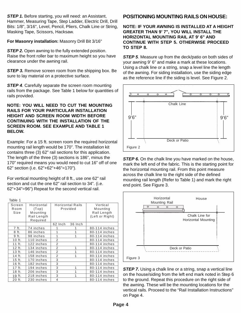
STEP 4. Carefully separate the screen room mountingrails from the package. See Table 1 below for quantities ofrails provided.
NOTE: YOU WILL NEED TO CUT THE MOUNTINGRAILS FOR YOUR PARTICULAR INSTALLATIONHEIGHT AND SCREEN ROOM WIDTH BEFORECONTINUING WITH THE INSTALLATION OF THESCREEN ROOM. SEE EXAMPLE AND TABLE 1BELOW.
Example: For a 15 ft. screen room the required horizontalmounting rail length would be 170”. The installation kitcontains three (3) 62” rail sections for this application.The length of the three (3) sections is 186”, minus the170” required means you would need to cut 16” off of one62” section (i.e. 62"+62"+46"=170").
For vertical mounting height of 8 ft., use one 62” railsection and cut the one 62” rail section to 34”. (i.e.62"+34"=96") Repeat for the second vertical rail.
POSITIONING MOUNTING RAILS ON HOUSE:
NOTE: IF YOUR AWNING IS INSTALLED AT A HEIGHTGREATER THAN 9’ 7", YOU WILL INSTALL THEHORIZONTAL MOUNTING RAIL AT 9’ 6" ANDCONTINUE WITH STEP 5. OTHERWISE PROCEEDTO STEP 8.
STEP 5. Measure up from the deck/patio on both sides ofyour awning 9’ 6" and make a mark at these locations.Using a chalk line or a string, snap a level line the lengthof the awning. For siding installation, use the siding edgeas the reference line if the siding is level. See Figure 2.
STEP 6. On the chalk line you have marked on the house,mark the left end of the fabric. This is the starting point forthe horizontal mounting rail. From this point measureacross the chalk line to the right side of the definedmounting rail length (Refer to Table 1) and mark the rightend point. See Figure 3.
Awning Fabric Rail
STEP 7. Using a chalk line or a string, snap a vertical lineon the house/siding from the left end mark noted in Step 6to the ground. Repeat this procedure on the right side ofthe awning. These will be the mounting locations for thevertical rails. Proceed to the “Rail Installation Instructions”on Page 4.
Deck or Patio
HorizontalMounting Rail
Chalk Line forHorizontal Mounting
House
Figure 3
chalk line
- - - - - - - - - - - - - - - - - - - - - - - - - - - - - - - - -
- - - - - - - - - - - - - - - - - - - - - - - - - - - - - - - - -
9’6”
X X
Figure 2
- - - -
- - - - deck/patio
9’6”
Awning Fabric Rail
9’6”
Figure 2
Chalk Line
Deck or Patio
9’6”9’6”
Screen R oom S ize
H orizonta l (Top)
M ounting R ail Length
R equ ired
H orizonta l R ails Provided
Vertica l M ounting
R ail Length (Left or R ight)
62 Inch 36 Inch 7 ft. 74 inches 1 1 80-114 inches 8 ft. 86 inches 1 1 80-114 inches 9 ft. 98 inches 1 1 80-114 inches
10 ft. 110 inches 2 80-114 inches 11 ft. 122 inches 2 80-114 inches 12 ft. 134 inches 2 1 80-114 inches 13 ft. 146 inches 2 1 80-114 inches 14 ft. 158 inches 2 1 80-114 inches 15 ft. 170 inches 3 80-114 inches 16 ft. 182 inches 3 80-114 inches 17 ft. 194 inches 3 1 80-114 inches 18 ft. 206 inches 3 1 80-114 inches 18 ft. 218 inches 3 1 80-114 inches 20 ft. 230 inches 4 80-114 inches
Table 1
19
Page 5
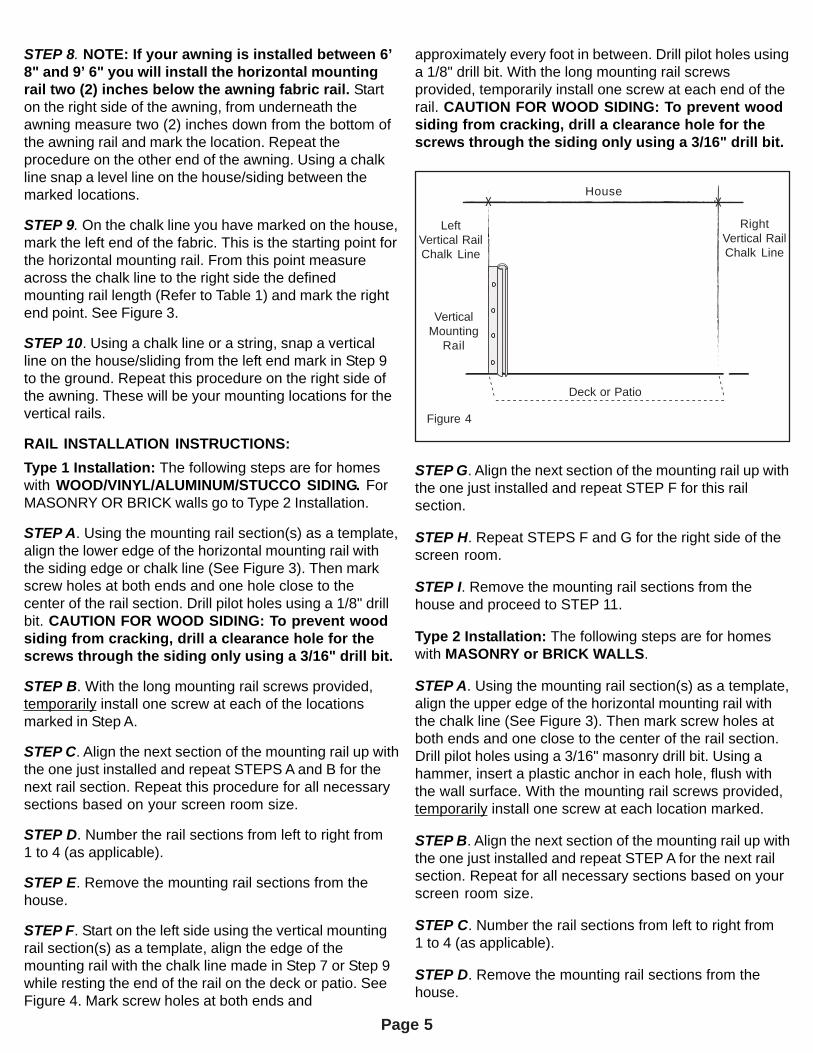
STEP 8. NOTE: If your awning is installed between 6’8" and 9’ 6" you will install the horizontal mountingrail two (2) inches below the awning fabric rail. Starton the right side of the awning, from underneath theawning measure two (2) inches down from the bottom ofthe awning rail and mark the location. Repeat theprocedure on the other end of the awning. Using a chalkline snap a level line on the house/siding between themarked locations.
STEP 9. On the chalk line you have marked on the house,mark the left end of the fabric. This is the starting point forthe horizontal mounting rail. From this point measureacross the chalk line to the right side the definedmounting rail length (Refer to Table 1) and mark the rightend point. See Figure 3.
STEP 10. Using a chalk line or a string, snap a verticalline on the house/sliding from the left end mark in Step 9to the ground. Repeat this procedure on the right side ofthe awning. These will be your mounting locations for thevertical rails.
RAIL INSTALLATION INSTRUCTIONS:Type 1 Installation: The following steps are for homeswith WOOD/VINYL/ALUMINUM/STUCCO SIDING. ForMASONRY OR BRICK walls go to Type 2 Installation.
STEP A. Using the mounting rail section(s) as a template,align the lower edge of the horizontal mounting rail withthe siding edge or chalk line (See Figure 3). Then markscrew holes at both ends and one hole close to thecenter of the rail section. Drill pilot holes using a 1/8" drillbit. CAUTION FOR WOOD SIDING: To prevent woodsiding from cracking, drill a clearance hole for thescrews through the siding only using a 3/16" drill bit.
STEP B. With the long mounting rail screws provided,temporarily install one screw at each of the locationsmarked in Step A.
STEP C. Align the next section of the mounting rail up withthe one just installed and repeat STEPS A and B for thenext rail section. Repeat this procedure for all necessarysections based on your screen room size.
STEP D. Number the rail sections from left to right from1 to 4 (as applicable).
STEP E. Remove the mounting rail sections from thehouse.
STEP F. Start on the left side using the vertical mountingrail section(s) as a template, align the edge of themounting rail with the chalk line made in Step 7 or Step 9while resting the end of the rail on the deck or patio. SeeFigure 4. Mark screw holes at both ends and
approximately every foot in between. Drill pilot holes usinga 1/8" drill bit. With the long mounting rail screwsprovided, temporarily install one screw at each end of therail. CAUTION FOR WOOD SIDING: To prevent woodsiding from cracking, drill a clearance hole for thescrews through the siding only using a 3/16" drill bit.
STEP G. Align the next section of the mounting rail up withthe one just installed and repeat STEP F for this railsection.
STEP H. Repeat STEPS F and G for the right side of thescreen room.
STEP I. Remove the mounting rail sections from thehouse and proceed to STEP 11.
Type 2 Installation: The following steps are for homeswith MASONRY or BRICK WALLS.
STEP A. Using the mounting rail section(s) as a template,align the upper edge of the horizontal mounting rail withthe chalk line (See Figure 3). Then mark screw holes atboth ends and one close to the center of the rail section.Drill pilot holes using a 3/16" masonry drill bit. Using ahammer, insert a plastic anchor in each hole, flush withthe wall surface. With the mounting rail screws provided,temporarily install one screw at each location marked.
STEP B. Align the next section of the mounting rail up withthe one just installed and repeat STEP A for the next railsection. Repeat for all necessary sections based on yourscreen room size.
STEP C. Number the rail sections from left to right from1 to 4 (as applicable).
STEP D. Remove the mounting rail sections from thehouse.
X X
- - - -
- - - - - - - - - - - - - - - - - - - - - - - - - - - - - - - - - - - - - - - - - - - -
Figure 4
House
Deck or Patio
VerticalMounting
Rail
LeftVertical RailChalk Line
RightVertical RailChalk Line
Page 6
STEP E. Start on the left side using the vertical mountingrail section(s) as a template, align the edge of themounting rail with the chalk line made in STEP 7 orSTEP 9 while resting the end of the rail on the deck orpatio. See Figure 4. Mark screw holes at both ends andapproximately every foot in between. Drill pilot holes using3/16" masonry drill bit. Using a hammer, insert a plasticanchor in each hole, flush with the wall surface. With themounting rail screws provided, temporarily install onescrew at each end of the rail.
STEP F. Align the next section of the mounting rail up withthe one just installed and repeat STEP E for this railsection.
STEP G. Repeat STEPS E and F for the right side of thescreen room.
STEP H. Remove the mounting rail sections from thehouse and proceed to STEP 11.
ATTACHING SCREEN ROOM TO THE HOUSE:
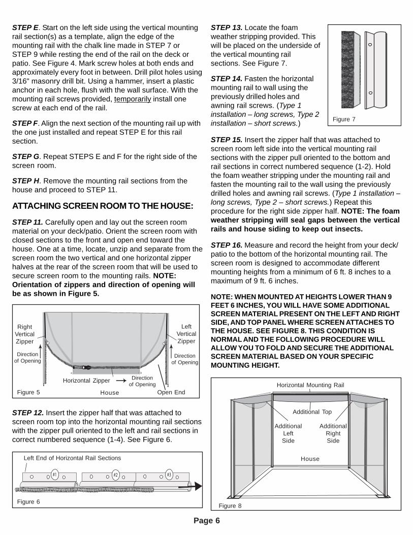
STEP 11. Carefully open and lay out the screen roommaterial on your deck/patio. Orient the screen room withclosed sections to the front and open end toward thehouse. One at a time, locate, unzip and separate from thescreen room the two vertical and one horizontal zipperhalves at the rear of the screen room that will be used tosecure screen room to the mounting rails. NOTE:Orientation of zippers and direction of opening willbe as shown in Figure 5.
STEP 12. Insert the zipper half that was attached toscreen room top into the horizontal mounting rail sectionswith the zipper pull oriented to the left and rail sections incorrect numbered sequence (1-4). See Figure 6.
STEP 13. Locate the foamweather stripping provided. Thiswill be placed on the underside ofthe vertical mounting railsections. See Figure 7.
STEP 14. Fasten the horizontalmounting rail to wall using thepreviously drilled holes andawning rail screws. (Type 1installation – long screws, Type 2installation – short screws.)
STEP 15. Insert the zipper half that was attached toscreen room left side into the vertical mounting railsections with the zipper pull oriented to the bottom andrail sections in correct numbered sequence (1-2). Holdthe foam weather stripping under the mounting rail andfasten the mounting rail to the wall using the previouslydrilled holes and awning rail screws. (Type 1 installation –long screws, Type 2 – short screws.) Repeat thisprocedure for the right side zipper half. NOTE: The foamweather stripping will seal gaps between the verticalrails and house siding to keep out insects.
STEP 16. Measure and record the height from your deck/patio to the bottom of the horizontal mounting rail. Thescreen room is designed to accommodate differentmounting heights from a minimum of 6 ft. 8 inches to amaximum of 9 ft. 6 inches.
NOTE: WHEN MOUNTED AT HEIGHTS LOWER THAN 9FEET 6 INCHES, YOU WILL HAVE SOME ADDITIONALSCREEN MATERIAL PRESENT ON THE LEFT AND RIGHTSIDE, AND TOP PANEL WHERE SCREEN ATTACHES TOTHE HOUSE. SEE FIGURE 8. THIS CONDITION ISNORMAL AND THE FOLLOWING PROCEDURE WILLALLOW YOU TO FOLD AND SECURE THE ADDITIONALSCREEN MATERIAL BASED ON YOUR SPECIFICMOUNTING HEIGHT.
Figure 7Figure 7
Left end of horizontal rail sections
#1 #2 #3
Figure 6
Left End of Horizontal Rail Sections
RightVerticalZipper
LeftVerticalZipper
Horizontal Zipper
Figure 5
Figure 8
Horizontal Mounting Rail
AdditionalLeftSide
AdditionalRightSide
Additional Top
House
Directionof Opening
Directionof Opening
Directionof Opening
House Open End
Page 7
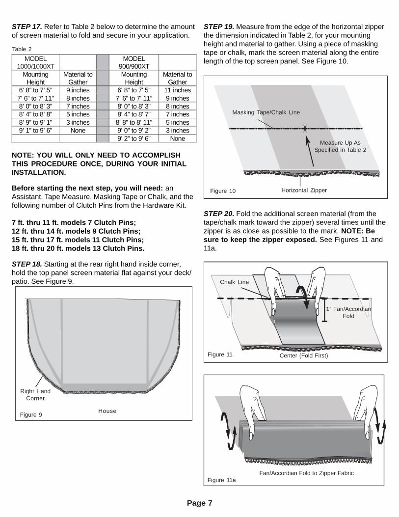
STEP 17. Refer to Table 2 below to determine the amountof screen material to fold and secure in your application.
NOTE: YOU WILL ONLY NEED TO ACCOMPLISHTHIS PROCEDURE ONCE, DURING YOUR INITIALINSTALLATION.
Before starting the next step, you will need: anAssistant, Tape Measure, Masking Tape or Chalk, and thefollowing number of Clutch Pins from the Hardware Kit.
7 ft. thru 11 ft. models 7 Clutch Pins;12 ft. thru 14 ft. models 9 Clutch Pins;15 ft. thru 17 ft. models 11 Clutch Pins;18 ft. thru 20 ft. models 13 Clutch Pins.
STEP 18. Starting at the rear right hand inside corner,hold the top panel screen material flat against your deck/patio. See Figure 9.
STEP 19. Measure from the edge of the horizontal zipperthe dimension indicated in Table 2, for your mountingheight and material to gather. Using a piece of maskingtape or chalk, mark the screen material along the entirelength of the top screen panel. See Figure 10.MODEL
1000/1000XT MODEL
900/900XT Mounting
Height Material to
Gather Mounting
Height Material to
Gather 6’ 8” to 7’ 5” 9 inches 6’ 8” to 7’ 5” 11 inches 7’ 6” to 7’ 11” 8 inches 7’ 6” to 7’ 11” 9 inches 8’ 0” to 8’ 3” 7 inches 8’ 0” to 8’ 3” 8 inches 8’ 4” to 8’ 8” 5 inches 8’ 4” to 8’ 7” 7 inches 8’ 9” to 9’ 1” 3 inches 8’ 8” to 8’ 11” 5 inches 9’ 1” to 9’ 6” None 9’ 0” to 9’ 2” 3 inches
9’ 2” to 9’ 6” None
Fan Fold to Zipper FabricFigure 11a
STEP 20. Fold the additional screen material (from thetape/chalk mark toward the zipper) several times until thezipper is as close as possible to the mark. NOTE: Besure to keep the zipper exposed. See Figures 11 and11a.
Figure 11
X
Figure 10
Masking Tape/Chalk Line
Measure Up AsSpecified in Table 2
Figure 10
Figure 11
Figure 11aFan/Accordian Fold to Zipper Fabric
Center (Fold First)
Chalk Line
1” Fan/AccordianFold
Figure 9
Table 2
Figure 9
Right HandCorner
House
Horizontal Zipper
Page 8
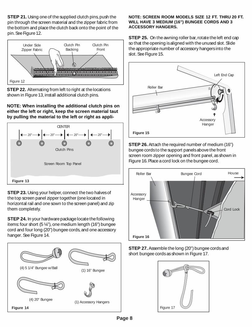
NOTE: SCREEN ROOM MODELS SIZE 12 FT. THRU 20 FT. WILL HAVE 3 MEDIUM (16”) BUNGEE CORDS AND 3ACCESSORY HANGERS.
STEP 25. On the awning roller bar, rotate the left end capso that the opening isaligned with the unused slot.Slidethe appropriate number of accessory hangers into theslot.See Figure 15.
STEP 21. Using one of the supplied clutch pins,push thepin through the screen material and the zipper fabric fromthe bottom and place the clutch back onto the point of thepin.SeeFigure12.
STEP 23. Using your helper, connect the two halves ofthe top screen panel zipper together (one located inhorizontal rail and one sown to the screen panel) and zipthem completely.
STEP 24. In your hardware package locate the followingitems: four short (5 ¼”), one medium length (16") bungeecord and four long (20") bungee cords,and one accessoryhanger. See Figure 14.
STEP 26. Attach the required number of medium (16”)bungee cords to the support panelsabove the frontscreen room zipper opening and front panel, as shown inFigure 16. Place a cord lock on the bungee cord.
20” 20” 20” 20”
Figure 13
Screen Room Top Panel
CENTER
Clutch Pins
Figure 14Figure 14
(4) 5 1/4” Bungee w/Ball (1) 16” Bungee
(1) Accessory Hangers(4) 20” Bungee
Figure 12
Under SideZipper Fabric
Clutch PinBacking
Clutch PinFront
Figure 17
Roller Bar
AccessoryHanger
Bungee Cord House
STEP 27. Assemble the long (20”) bungee cordsandshort bungee cords as shown in Figure 17.
Figure 16
Figure 15
Roller Bar
Left End Cap
AccessoryHanger
Figure 16
Figure 17
Figure 15
Cord Lock
STEP 22. Alternating from left to right at the locationsshown in Figure 13, install additional clutch pins.
NOTE: When installing the additional clutch pins oneither the left or right, keep the screen material taut by pulling the material to the left or right as appli-
Page 9
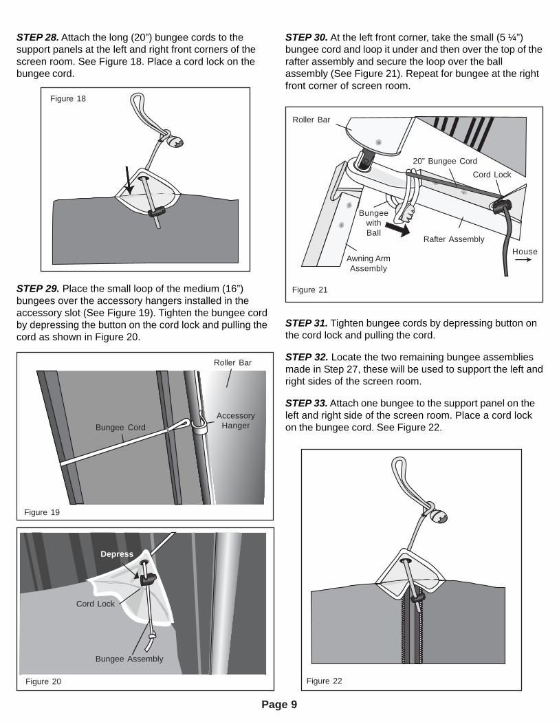
STEP 28. Attach the long (20”) bungee cords to thesupport panels at the left and right front corners of thescreen room. See Figure 18. Place a cord lock on thebungee cord.
STEP 30. At the left front corner, take the small (5 ¼”)bungee cord and loop it under and then over the top of therafter assembly and secure the loop over the ballassembly (See Figure 21). Repeat for bungee at the rightfront corner of screen room.
STEP 29. Place the small loop of the medium (16”)bungees over the accessory hangers installed in theaccessory slot (See Figure 19). Tighten the bungee cordby depressing the button on the cord lock and pulling thecord as shown in Figure 20.
STEP 31. Tighten bungee cords by depressing button onthe cord lock and pulling the cord.
STEP 32. Locate the two remaining bungee assembliesmade in Step 27, these will be used to support the left andright sides of the screen room.
STEP 33. Attach one bungee to the support panel on theleft and right side of the screen room. Place a cord lockon the bungee cord. See Figure 22.
Figure 19
Roller Bar
AccessoryHangerBungee Cord
Depress Buttons
Figure 22
Figure 21
Roller Bar
BungeewithBall
Awning ArmAssembly
Rafter Assembly
20” Bungee CordCord Lock
House
Figure 19
Figure 20
Figure 18
Depress
Cord Lock
Bungee Assembly
Page 10
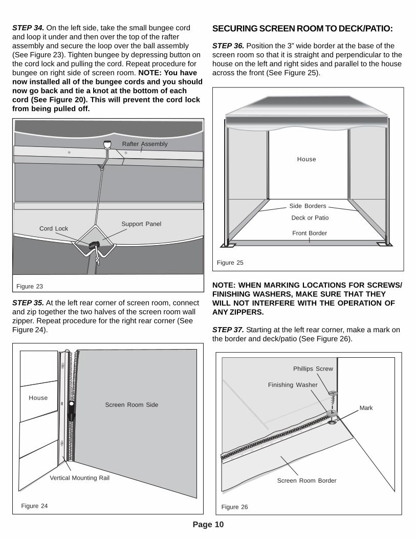
STEP 34. On the left side, take the small bungee cordand loop it under and then over the top of the rafterassembly and secure the loop over the ball assembly(See Figure 23). Tighten bungee by depressing button onthe cord lock and pulling the cord. Repeat procedure forbungee on right side of screen room. NOTE: You havenow installed all of the bungee cords and you shouldnow go back and tie a knot at the bottom of eachcord (See Figure 20). This will prevent the cord lockfrom being pulled off.
SECURING SCREEN ROOM TO DECK/PATIO:
STEP 36. Position the 3” wide border at the base of thescreen room so that it is straight and perpendicular to thehouse on the left and right sides and parallel to the houseacross the front (See Figure 25).
STEP 35. At the left rear corner of screen room, connectand zip together the two halves of the screen room wallzipper. Repeat procedure for the right rear corner (SeeFigure 24).
NOTE: WHEN MARKING LOCATIONS FOR SCREWS/FINISHING WASHERS, MAKE SURE THAT THEYWILL NOT INTERFERE WITH THE OPERATION OFANY ZIPPERS.
STEP 37. Starting at the left rear corner, make a mark onthe border and deck/patio (See Figure 26).
Figure 24Figure 24
House
Vertical Mounting Rail
Screen Room Side
Figure 25Figure 25
Front Border
Deck or Patio
House
Figure 26Figure 26
Screen Room Border
Phillips Screw
Finishing Washer
Side Borders
Mark
Figure 23
Cord LockSupport Panel
Rafter Assembly
Page 11
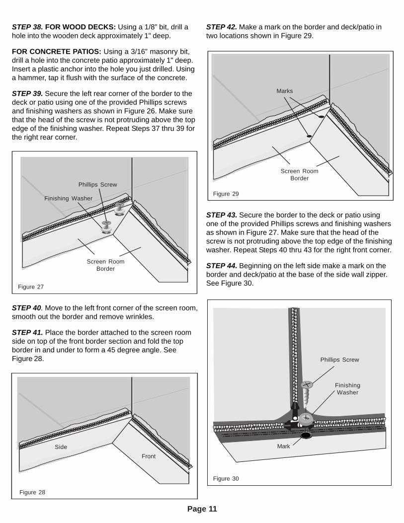
STEP 38. FOR WOOD DECKS: Using a 1/8” bit, drill ahole into the wooden deck approximately 1" deep.
FOR CONCRETE PATIOS: Using a 3/16” masonry bit,drill a hole into the concrete patio approximately 1" deep.Insert a plastic anchor into the hole you just drilled. Usinga hammer, tap it flush with the surface of the concrete.
STEP 39. Secure the left rear corner of the border to thedeck or patio using one of the provided Phillips screwsand finishing washers as shown in Figure 26. Make surethat the head of the screw is not protruding above the topedge of the finishing washer. Repeat Steps 37 thru 39 forthe right rear corner.
STEP 40. Move to the left front corner of the screen room,smooth out the border and remove wrinkles.
STEP 41. Place the border attached to the screen roomside on top of the front border section and fold the topborder in and under to form a 45 degree angle. SeeFigure 28.
STEP 42. Make a mark on the border and deck/patio intwo locations shown in Figure 29.
STEP 43. Secure the border to the deck or patio usingone of the provided Phillips screws and finishing washersas shown in Figure 27. Make sure that the head of thescrew is not protruding above the top edge of the finishingwasher. Repeat Steps 40 thru 43 for the right front corner.
STEP 44. Beginning on the left side make a mark on theborder and deck/patio at the base of the side wall zipper.See Figure 30.Figure 27Figure 27
Screen RoomBorder
Phillips Screw
Finishing Washer
Figure 28Figure 28
FrontSide
Figure 29Figure 29
Marks
Screen RoomBorder
Figure 30Figure 30
Phillips Screw
FinishingWasher
Mark
Page 12
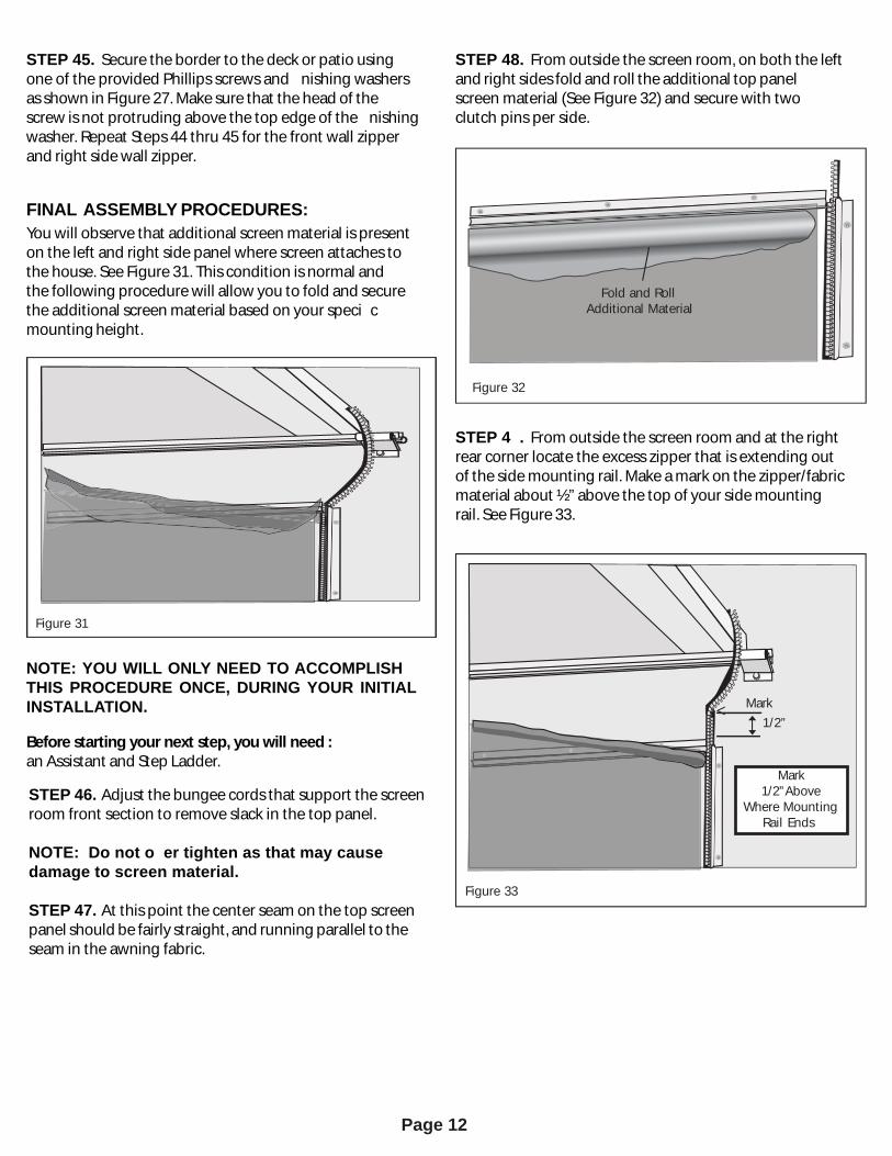
STEP 45. Secure the border to the deck or patio usingone of the provided Phillipsscrewsand nishing washersasshown in Figure27. Makesure that thehead of thescrew is not protruding above the top edge of the nishingwasher. Repeat Steps 44 thru 45 for the front wall zipperand right sidewall zipper.
FINAL ASSEMBLY PROCEDURES:You will observe that additional screen material ispresenton the left and right side panel where screen attaches tothe house. See Figure 31. This condition is normal andthe following procedure will allow you to fold and securethe additional screen material based on your speci cmounting height.
NOTE: YOU WILL ONLY NEED TO ACCOMPLISHTHIS PROCEDURE ONCE, DURING YOUR INITIALINSTALLATION.
Before starting your next step, you will need :an Assistant and Step Ladder.
STEP 48. From outside the screen room, on both the leftand right sides fold and roll theadditional top panelscreen material (See Figure 32) and secure with twoclutch pinsper side.
Figure 31Figure 31
Figure 33
Mark
Figure 32
Fold and RollAdditional Material
Figure 32
STEP 4 . From outside the screen room and at the rightrear corner locate the excess zipper that is extending outof the side mounting rail. Make a mark on the zipper/fabricmaterial about ½” above the top of your sidemountingrail.SeeFigure33.
Mark1/2”Above
Where MountingRail Ends
Figure 33
1/2”<
STEP 46. Adjust the bungee cordsthat support the screenroom front section to remove slack in the top panel.
NOTE: Do not o er tighten as that may cause damage to screen material.
STEP 47. At thispoint the center seam on the top screenpanel should be fairly straight,and running parallel to the seam in the awning fabric.
Page 13
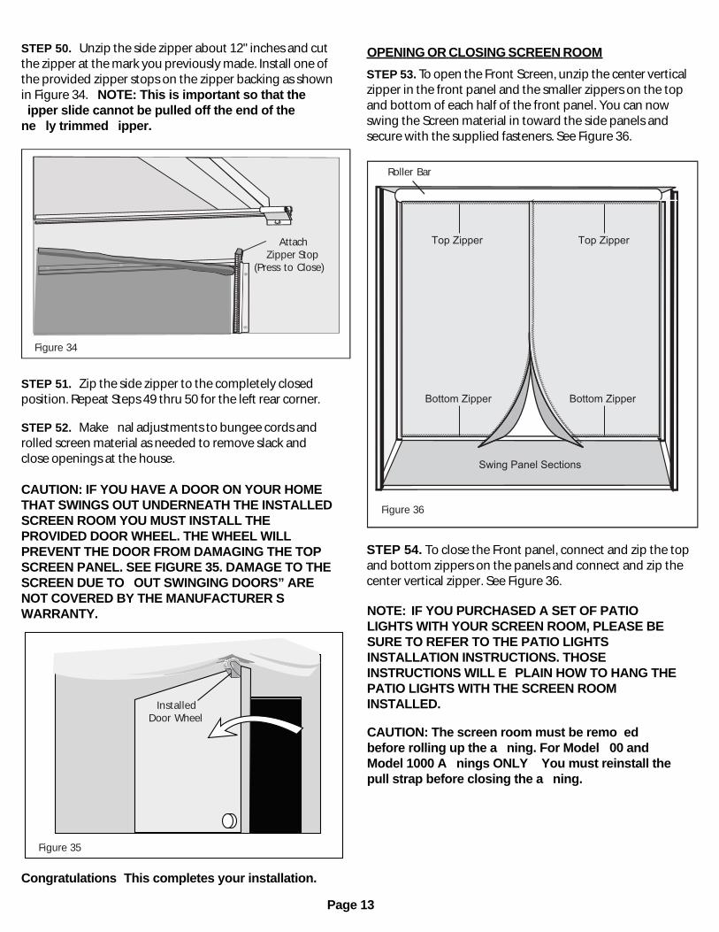
STEP 50. Unzip the side zipper about 12" inches and cutthe zipper at the mark you previously made. Install one ofthe provided zipper stops on the zipper backing as shownin Figure 34. NOTE: This is important so that theipper slide cannot be pulled off the end of the
ne ly trimmed ipper.
OPENING OR CLOSING SCREEN ROOM
STEP 51. Zip the side zipper to the completely closedposition.Repeat Steps49 thru 50 for the left rear corner.
STEP 52. Make nal adjustments to bungeecordsandrolled screen material asneeded to remove slack andclose openings at the house.
CAUTION: IF YOU HAVE A DOOR ON YOUR HOMETHAT SWINGS OUT UNDERNEATH THE INSTALLEDSCREEN ROOM YOU MUST INSTALL THEPROVIDED DOOR WHEEL. THE WHEEL WILLPREVENT THE DOOR FROM DAMAGING THE TOPSCREEN PANEL. SEE FIGURE 35. DAMAGE TO THESCREEN DUE TO OUT SWINGING DOORS” ARENOT COVERED BY THE MANUFACTURER SWARRANTY.
Figure 34Figure 34
AttachZipper Stop
(Press to Close)
Congratulations This completes your installation.
Figure 36Figure 36
Roller Bar
NOTE: IF YOU PURCHASED A SET OF PATIOLIGHTS WITH YOUR SCREEN ROOM, PLEASE BESURE TO REFER TO THE PATIO LIGHTSINSTALLATION INSTRUCTIONS. THOSEINSTRUCTIONS WILL E PLAIN HOW TO HANG THEPATIO LIGHTS WITH THE SCREEN ROOMINSTALLED.
CAUTION: The screen room must be remo edbefore rolling up the a ning. For Model 00 andModel 1000 A nings ONLY You must reinstall thepull strap before closing the a ning.
Figure 35Figure 35
InstalledDoor Wheel
vvvvvvvvvvvvvvvvvvvvvvvvvvvvvvvvvvvvvvvvvvvvvvvvvvvvvvvvvvvvvvvvvvv vvvvvvvvvvvvvvvvvvvvvvvvvvvvvvvvvvvvvvvvvvvvvvvvvvvvvvvvvvvvvvvvvvvvvvv
vvvvvvvvvvvvvvvvvvvvvvvvvvvvvvvvvvvvvvvvvvvvvvv
vvvvvvvvvvvvvvvvvvvvvvvvvvvvvvvvvvvvvvvvvvvvvvvvvvvvvvvvvvvvvvvvvvvv vvvvvvvvvvvvvvvvvvvvvvvvvvvvvvvvvvvvvvvvvvvvvvvvvvvvvvvvvvvvvvvvvvvvvvvvvvvvvvvvvvvvvvvvvvvvvvvvvvvvvvvvvvvvvvvvvvvvvvvvvvvvvvvvvvvvvvvvvvvvvvvvvvvvvvvvvvvvvvvvvvvvvvvvvvvvvvvvvvvvvvvvv
vvvvvvvvvvvvvvvvvvvvvvvvvvvvvvvvvvvvvvvvvvvvvvvvvvvvvvvvvvvvvvvvvvvv
Top Zipper Top Zipper
Bottom Zipper
Swing Panel Sections
Bottom Zipper
STEP 53. To open the Front Screen,unzip the center verticalzipper in the front panel and the smaller zippers on the top and bottom of each half of the front panel. You can now swing the Screen material in toward the side panels andsecure with the supplied fasteners. See Figure 36.
STEP 54. To close the Front panel, connect and zip the top and bottom zippers on the panels and connect and zip the center vertical zipper. See Figure 36.
Page 14
REMOVAL:
NOTE: A HELPER WILL BE REQUIRED TO SAFELYCOMPLETE THIS PROCEDURE.
STEP 1. Locate and loosen the cord locks on all thebungee cords on your screen room. Allow cord locks torest against the knot at the end of the bungee cord.
STEP 2. Starting at the right rear inside corner, unzip andseparate the screen room panels from the border that issecuring the screen room to your deck or patio.
STEP 3. Starting at the left rear corner, completely unzipthe screen room from the mounting rails.
STEP 4. Remove the bungee cords from around yourawning rafter assemblies and from the accessoryhangers in the front roller bar.
STEP 5. CAUTION: The accessory hangers must beremoved from the accessory slot of the roller barbefore the awning is retracted.
STEP 6. Carefully fold and remove the screen room andstore in a safe location.
STORAGE:
Care and MaintenanceIf the screen room is folded and stored when wet, themoisture will promote the formation of mildew.
If it was necessary to fold the screen room while wet, besure to allow it to dry when the weather is better. Whilethe screen won’t mildew, mildew can form on the dustand dirt that may accumulate on the screen.
CleaningDo not use caustic cleaners. To clean the screen materialuse a mild detergent and a soft bristle brush. Rinse withwater and let dry.
WARNING: DURING HIGH WINDS OR STORMYWEATHER, OR WHEN THE FORECAST IS UNCLEARAND COULD POSSIBLY BE STORMY THE SCREENROOM MUST BE REMOVED AND THE AWNINGFULLY RETRACTED AGAINST THE HOUSE.FAILURE TO DO SO COULD CAUSE PERSONALINJURY.
When Leaving the Awning UnattendedTo prevent water from accumulating and pooling on theawning fabric, you must set the awning with at least onearm angled back to the wall bracket, and lower that armto create enough drop (front to back) and allow for rainwater to run off. Please refer to your awning installation,operation and maintenance section for properinstructions.
WARNING: FAILURE TO TILT THE AWNING ENOUGHFOR APPROPRIATE DRAINAGE MAY RESULT IN THECOLLAPSE OF THE STRUCTURE, WHICH COULDCAUSE PERSONAL INJURY.
TROUBLE SHOOTING:
If…. Then….Mounting Rail was bent in shipping:
The mounting rail can be straightened by using a 3/8” wooden dowel. Call 1-800-670-7071 for a replacement section if necessary.
After installing, the screen room border is not under the awning fabric:
Reposition the screen room border so that it is under the awning fabric.
After installing, the screen room roof sags:
Check to see that the bungee assemblies are correctly installed and pulled tight. Note: Do not over- tighten as that may cause damage to screen material. Verify that correct amount of additional screen material was secured for your specific mounting height. See Table on Page 7. Check to see that “Clutch Pins” are installed properly.
After installing, you observe additional screen material on left and right sides where screen room attaches to the house:
Check to see that the “Final Assembly Procedures” on page 12 have been completed. Check to see that “Clutch Pins” are installed properly.
Clutch pins pop off:
Over-tightening of the bungee assemblies can cause clutch pins to come loose.

Rev 2/23/11 ©SunSetter Products, a Massachusetts Limited Partnership, 184 Charles Street, Malden, MA 02148