Embed Size (px)
Citation preview
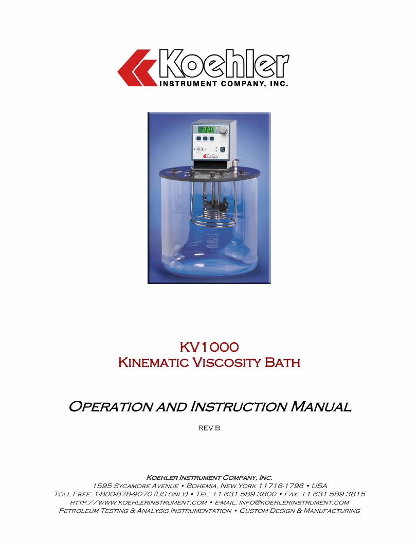
Operation and Instruction Manual
REV B
Koehler Instrument Company, Inc.
1595 Sycamore Avenue • Bohemia, New York 11716-1796 • USA
Toll Free: 1-800-878-9070 (US only) • Tel: +1 631 589 3800 • Fax: +1 631 589 3815
http://www.koehlerinstrument.com • e-mail: [email protected]
Petroleum Testing & Analysis Instrumentation • Custom Design & Manufacturing
KV1000
Kinematic Viscosity Bath

CERTIFICATE OF CONFORMANCE
Constant Temperature Kinematic Viscosity Bath, KV1000 K2337X
This certificate verifies that part number K2337X, Constant Temperature Kinematic Viscosity Bath, was manufactured in conformance with the applicable standards set forth in this certification. Specifications: ASTM D445
ASTM D2532 ASTM D6074 ASTM D6158 IP 71 ISO 3104 DIN 51550 FTM 791-305 NF T 60-100
This unit is tested before it leaves the factory, to ensure total functionality and compliance to the above specifications and ASTM standards. Test and inspection
records are on file for verification.
Jesse Kelly Application Engineer Koehler Instrument Company

KV1000 Kinematic Viscosity Bath Operation and Instruction Manual
KV1000-Manual -1-
Table of Contents
1. Introduction _______________________________________________________ 3
1.2 Recommended Resources and Publications _____________________________________________ 3
1.3 Instrument Specifications ______________________________________________________________ 4
1.4 Environmental Conditions _____________________________________________________________ 4
2. Safety Information and Warnings _____________________________________ 4
3. Getting Started ____________________________________________________ 5
3.1 Packing List _________________________________________________________________________ 5
3.2 Unpacking ___________________________________________________________________________ 5
3.3 Setup _______________________________________________________________________________ 5
4. Descriptions ______________________________________________________ 5
4.1 Instrument Controls ___________________________________________________________________ 5
4.2 Temperature Controller ________________________________________________________________ 6
4.3 Accessories for Running Tests _________________________________________________________ 6
4.4 Recommended Accessories ___________________________________________________________ 8
5 Operation _________________________________________________________ 8
5.1 Bath ________________________________________________________________________________ 8
5.2 Power ______________________________________________________________________________ 8
5.3 Circulator Pump ______________________________________________________________________ 9
5.4 Temperature Controller Operation ______________________________________________________ 9
6 Safety Features ___________________________________________________ 12
6.1 Over Temperature Protection _________________________________________________________ 12
6.2 Over Power Protection _______________________________________________________________ 12
7 Maintenance _____________________________________________________ 12
7.3 Routine Maintenance ________________________________________________________________ 12
7.4 Replacement Parts __________________________________________________________________ 13
8 Troubleshooting __________________________________________________ 13
8.1 Unit Will Not Operate (no heat, cooling, or pumping) _______________________________________ 13
8.2 No Pumping ________________________________________________________________________ 13
8.3 Slow or Insufficient Pumping __________________________________________________________ 13
9 Service __________________________________________________________ 13
KV1000 Kinematic Viscosity Bath Operation and Instruction Manual
KV1000-Manual -2-
10 Storage _________________________________________________________ 13
11 Warranty ________________________________________________________ 13
12 Returned Goods Policy ____________________________________________ 14
Notes ______________________________________________________________ 15
KV1000 Kinematic Viscosity Bath Operation and Instruction Manual
KV1000-Manual -3-
1 Introduction
The Koehler KV1000 Kinematic Viscosity Bath is for performing kinematic viscosity tests with glass capillary viscometers according to the ASTM D445 test method and related test specifications.
This manual provides important information
regarding safety, technical reference, installation requirements, operating condition specifications, user facility resource requirements, and operating instructions for the Kinematic Viscosity Bath. This manual should also be used in conjunction with applicable published laboratory procedures. Information on these procedures is given in section 1.2.
1.1 Koehler's Commitment to Our Customers
Providing quality testing instrumentation and technical support services for research and testing laboratories has been our specialty for more than 50 years. At Koehler, the primary focus of our business is to provide you with the full support of your laboratory testing needs. Our products are backed by our staff of technically knowledgeable, trained specialists who are experienced in both petroleum products testing and instrument service to better understand your requirements and provide you with the best solutions. You can depend on Koehler for a full range of accurate and reliable instrumentation as well as support for your laboratory testing programs. Please do not hesitate to contact us at any time with your inquiries about equipment, tests, or technical support.
Toll Free: 1-800-878-9070 (US only) Tel: +1 631 589 3800 Fax: +1 631 589 3815 Email: [email protected] http://www.koehlerinstrument.com
1.2 Recommended Resources and Publications
1. American Society for Testing and Materials (ASTM)
100 Barr Harbor Drive West Conshohocken, Pennsylvania 19428- 2959, USA
Tel: +1 610 832 9500 Fax: +1 610 832 9555 http://www.astm.org email: [email protected]
ASTM Publication:
ASTM D445: Kinematic Viscosity of Transparent and Opaque Liquids (and the Calculation of Dynamic Viscosity)
ASTM D6074: Standard Guide for Characterizing Hydrocarbon Lubricant Base Oils
ASTM D6158: Standard Specification for Mineral Hydraulic Oils
2. International Organization for Standardization
(ISO) 1, rue de Varembé Case postale 56 CH-1211 Geneva 20, Switzerland Tel: 41 22 749 01 11 Fax: 41 22 733 34 30 http://www.iso.org
ISO Publication:
ISO 3104: Petroleum products-Transparent and Opaque Liquids- Determination of Kinematic Viscosity and Calculation of Dynamic Viscosity
3. Energy Institute (IP)
61 New Cavendish Street London, WIM 8AR, United Kingdom Tel: 44 (0)20 7467 7100 Fax: 44 (0)20 7255 1472 http://www.energyinstpubs.org.uk/
IP Publication:
IP 71: Kinematic Viscosity and Calculation of Dynamic Viscosity
4. Deutsche International Norm (DIN)
http://www.din.de
DIN Publication:
DIN 51550: Determination of Kinematic Viscosity and Dynamic Viscosity
5. Federal Test Method (FTM)
FTM Publication: 4.1 FTM 791-305: Kinematic Viscosity of
Petroleum Products
KV1000 Kinematic Viscosity Bath Operation and Instruction Manual
KV1000-Manual -4-
6. Association Francaise de Normalisation (ANFOR) http://www.anfor.fr ANFOR Publication: 4.2 NFT 60-100: Kinematic Viscosity of
Petroleum Products
1.3 Instrument Specifications
Models: K23376, K23371, K23377, K23378, K23373, K23374
Electrical Requirements:
115V 60 Hz 220-240V 50/60 Hz
Temperature Range:
Ambient to 150°C (302°F)
Temperature Control Stability:
±0.05°C
Viscometer Ports: Seven (6) Round 2” (51mm) ports
Capacity: Seven (6) Glass Capillary Viscometers
Bath Medium: Water or suitable head transfer fluid
Bath Medium Capacity:
22L (5.8 gal) or 34 L (8.9 gal)
Pump Speed: 2-Speed: 9 L/min & 15 L/min
1.4 Environmental Conditions
- Indoor Use Only - Over Voltage: Category ll - Maximum Altitude: 2000 meters
- Operating Ambient: 5 to 30C
- Relative Humidity: 80% for temperatures
to 30C
- Pollution Degree: 2 - Class 1: Residential, Commercial, Light Industrial - Class 2: Heavy Industrial
2 Safety Information and Warnings
Safety Considerations. The use of this equipment may involve hazardous materials and operations. This manual does not purport to address all of the safety problems associated with the use of this equipment. It is the responsibility of any user of this equipment to investigate, research, and establish appropriate safety and health practices and determine the applicability of regulatory limitations prior to use. Equipment Modifications and Replacement Parts. Any modification or alteration of this equipment from that of factory specifications is not recommended voids the manufacturer warranty, product safety, performance specifications, and/or certifications whether specified or implied, and may result in personal injury and/or property loss. Replacement parts must be O.E.M exact replacement equipment. Unit Design. This equipment is specifically designed for use in accordance with the applicable standard test methods listed in section 1.2 of this manual. The use of this equipment in accordance with any other test procedures, or for any other purpose, is not recommended and may be extremely hazardous. Over Temperature Protection. This unit is equipped with Over Temperature Protection (OTP) circuitry to prevent overheating. The unit will automatically interrupt power whether equipment malfunction or operator error causes the temperature to exceed either 20 °C above the set point or the maximum recommended temperature range. The power can only then be restored by identifying and correcting the problem, Allowing the unit to return to normal operating temperatures, and resetting the power to the unit. Chemical Reagents Information. Chemicals and reagents used in performing the test may exhibit potential hazards. Any user must be familiarized with the possible dangers before use. We also recommend consulting the Material Safety Data Sheet (MSDS) on each chemical reagent for additional information. MSDS information can easily be found at http://siri.uvm.edu or http://www.sigma-aldrich.com.
KV1000 Kinematic Viscosity Bath Operation and Instruction Manual
KV1000-Manual -5-
3 Getting Started
The instructions for preparing the equipment assume that the user is aware of the contents of this document, which lists the warranty conditions and important precautions.
3.1 Packing List
KV1000 Digital Constant Temperature Kinematic Viscosity Bath
Round Viscometer Port Cover (6)
Thermometer Holder (2)
Tapered Plug (2)
KV1000-Manual KV1000 Operation and Instruction Manual
IEC Power Cord
3.2 Unpacking
Carefully unpack and place the instrument and accessories in a secure location. Use extra care while unpacking the Pyrex® glass jar. Ensure that all parts listed on the packing list are present. Inspect the unit and all accessories for damage. If any damage is found, keep all packing materials and immediately report the damage to the carrier. We will assist you with your claim, if requested. When submitting a claim for shipping damage, request that the carrier inspect the shipping container and equipment. Do not return goods to Koehler without written authorization.
3.3 Setup
Equipment Placement. Place the instrument on a firm, level table in an area with adequate ventilation or in a hood. Please note that Koehler does not supply a level with this equipment. Ventilation. A fume hood or exhaust system is required when operating the unit. Flammable vapors and/or steam are generated during operation and must not be permitted to accumulate. A canopy-style hood may be used if the height from the top of the unit to the canopy is 5 feet or less. The exhaust blower should have a rating of 1000 C.F.M or greater.
Power. Connect the line cords to properly fused and grounded receptacles with the correct voltage as indicated in section 1.3 or on the back of the unit.
WARNING: For safety, disconnect the power when performing any maintenance and/or cleaning. Do NOT turn the power on unless the bath is filled with the proper medium; otherwise, damage may occur to the unit and the warranty will be void.
4 Descriptions
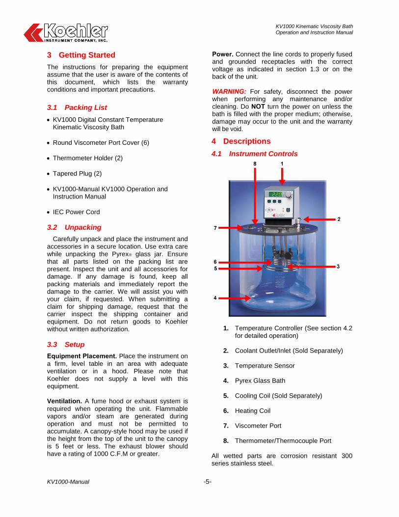
4.1 Instrument Controls
1. Temperature Controller (See section 4.2 for detailed operation)
2. Coolant Outlet/Inlet (Sold Separately)
3. Temperature Sensor
4. Pyrex Glass Bath
5. Cooling Coil (Sold Separately)
6. Heating Coil 7. Viscometer Port
8. Thermometer/Thermocouple Port
All wetted parts are corrosion resistant 300 series stainless steel.
KV1000 Kinematic Viscosity Bath Operation and Instruction Manual
KV1000-Manual -6-
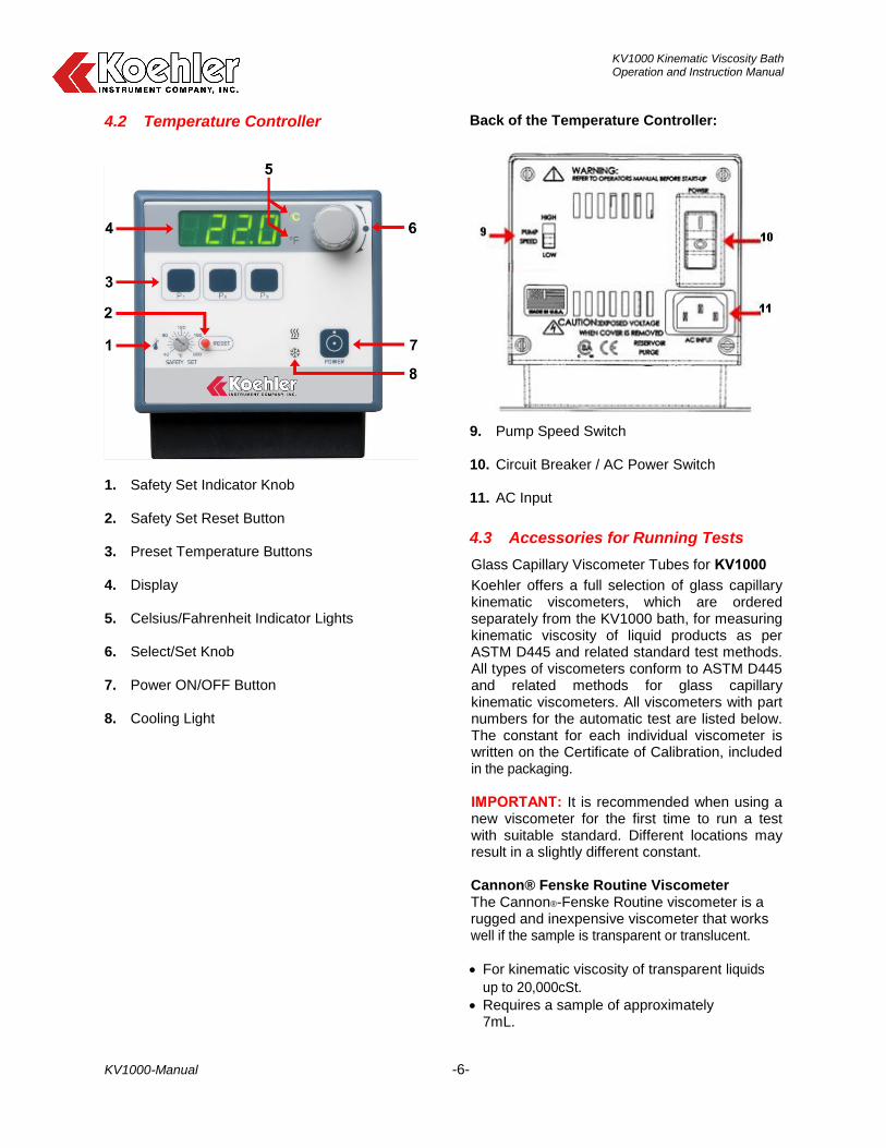
4.2 Temperature Controller
1. Safety Set Indicator Knob 2. Safety Set Reset Button 3. Preset Temperature Buttons 4. Display 5. Celsius/Fahrenheit Indicator Lights 6. Select/Set Knob 7. Power ON/OFF Button 8. Cooling Light
Back of the Temperature Controller:
9. Pump Speed Switch 10. Circuit Breaker / AC Power Switch 11. AC Input
4.3 Accessories for Running Tests
Glass Capillary Viscometer Tubes for KV1000
Koehler offers a full selection of glass capillary kinematic viscometers, which are ordered separately from the KV1000 bath, for measuring kinematic viscosity of liquid products as per ASTM D445 and related standard test methods. All types of viscometers conform to ASTM D445 and related methods for glass capillary kinematic viscometers. All viscometers with part numbers for the automatic test are listed below. The constant for each individual viscometer is written on the Certificate of Calibration, included in the packaging.
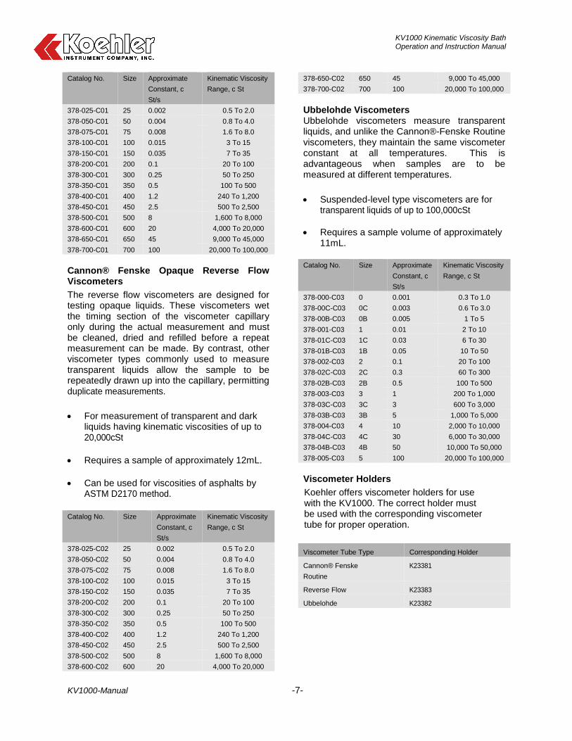
IMPORTANT: It is recommended when using a new viscometer for the first time to run a test with suitable standard. Different locations may result in a slightly different constant. Cannon® Fenske Routine Viscometer The Cannon®-Fenske Routine viscometer is a rugged and inexpensive viscometer that works well if the sample is transparent or translucent.
For kinematic viscosity of transparent liquids
up to 20,000cSt.
Requires a sample of approximately 7mL.
KV1000 Kinematic Viscosity Bath Operation and Instruction Manual
KV1000-Manual -7-
Catalog No. Size Approximate
Constant, c
St/s
Kinematic Viscosity
Range, c St
378-025-C01 25 0.002 0.5 To 2.0
378-050-C01 50 0.004 0.8 To 4.0
378-075-C01 75 0.008 1.6 To 8.0
378-100-C01 100 0.015 3 To 15
378-150-C01 150 0.035 7 To 35
378-200-C01 200 0.1 20 To 100
378-300-C01 300 0.25 50 To 250
378-350-C01 350 0.5 100 To 500
378-400-C01 400 1.2 240 To 1,200
378-450-C01 450 2.5 500 To 2,500
378-500-C01 500 8 1,600 To 8,000
378-600-C01 600 20 4,000 To 20,000
378-650-C01 650 45 9,000 To 45,000
378-700-C01 700 100 20,000 To 100,000
Cannon® Fenske Opaque Reverse Flow Viscometers
The reverse flow viscometers are designed for testing opaque liquids. These viscometers wet the timing section of the viscometer capillary only during the actual measurement and must be cleaned, dried and refilled before a repeat measurement can be made. By contrast, other viscometer types commonly used to measure transparent liquids allow the sample to be repeatedly drawn up into the capillary, permitting duplicate measurements.
For measurement of transparent and dark liquids having kinematic viscosities of up to 20,000cSt
Requires a sample of approximately 12mL.
Can be used for viscosities of asphalts by ASTM D2170 method.
Catalog No. Size Approximate
Constant, c
St/s
Kinematic Viscosity
Range, c St
378-025-C02 25 0.002 0.5 To 2.0
378-050-C02 50 0.004 0.8 To 4.0
378-075-C02 75 0.008 1.6 To 8.0
378-100-C02 100 0.015 3 To 15
378-150-C02 150 0.035 7 To 35
378-200-C02 200 0.1 20 To 100
378-300-C02 300 0.25 50 To 250
378-350-C02 350 0.5 100 To 500
378-400-C02 400 1.2 240 To 1,200
378-450-C02 450 2.5 500 To 2,500
378-500-C02 500 8 1,600 To 8,000
378-600-C02 600 20 4,000 To 20,000
378-650-C02 650 45 9,000 To 45,000
378-700-C02 700 100 20,000 To 100,000
Ubbelohde Viscometers Ubbelohde viscometers measure transparent liquids, and unlike the Cannon®-Fenske Routine viscometers, they maintain the same viscometer constant at all temperatures. This is advantageous when samples are to be measured at different temperatures.
Suspended-level type viscometers are for transparent liquids of up to 100,000cSt
Requires a sample volume of approximately 11mL.
Catalog No. Size Approximate
Constant, c
St/s
Kinematic Viscosity
Range, c St
378-000-C03 0 0.001 0.3 To 1.0
378-00C-C03 0C 0.003 0.6 To 3.0
378-00B-C03 0B 0.005 1 To 5
378-001-C03 1 0.01 2 To 10
378-01C-C03 1C 0.03 6 To 30
378-01B-C03 1B 0.05 10 To 50
378-002-C03 2 0.1 20 To 100
378-02C-C03 2C 0.3 60 To 300
378-02B-C03 2B 0.5 100 To 500
378-003-C03 3 1 200 To 1,000
378-03C-C03 3C 3 600 To 3,000
378-03B-C03 3B 5 1,000 To 5,000
378-004-C03 4 10 2,000 To 10,000
378-04C-C03 4C 30 6,000 To 30,000
378-04B-C03 4B 50 10,000 To 50,000
378-005-C03 5 100 20,000 To 100,000
Viscometer Holders
Koehler offers viscometer holders for use with the KV1000. The correct holder must be used with the corresponding viscometer tube for proper operation.
Viscometer Tube Type Corresponding Holder
Cannon® Fenske
Routine
K23381
Reverse Flow K23383
Ubbelohde K23382
KV1000 Kinematic Viscosity Bath Operation and Instruction Manual
KV1000-Manual -8-
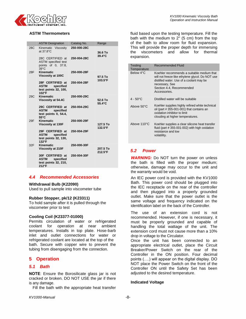
ASTM Thermometers
ASTM Designation Catalog No. Range
28C Kinematic Viscosity at 37.8°C 28C CERTIFIED at ASTM specified test points of 0, 37.8, 39°C
250-000-28C 250-004-28C
36.6 To 39.4°C
28F Kinematic Viscosity at 100C 28F CERTIFIED at ASTM specified test points 32, 100, 102°F
250-000-28F 250-004-28F
97.5 To 103.5°F
29C Kinematic Viscosity at 54.4C 29C CERTIFIED at ASTM specified test points 0, 54.4, 55°C
250-000-29C 250-004-29C
52.6 To 55.4°C
29F Kinematic Viscosity at 130F 29F CERTIFIED at ASTM specified test points 32, 130, 132°F
250-000-29F 250-004-29F
127.5 To 132.5°F
32F Kinematic Viscosity at 210F 30F CERTIFIED at ASTM specified test points 32, 210, 212°F
250-000-30F 250-004-30F
207.5 To 212.5°F
4.4 Recommended Accessories
Withdrawal Bulb (K22090) Used to pull sample into viscometer tube Rubber Stopper, pk/12 (K23311) To hold sample after it is pulled through the viscometer prior to test Cooling Coil (K23377-01000) Permits circulation of water or refrigerated coolant for operation at near ambient temperatures. Installs in top plate. Hose-barb inlet and outlet connections for water or refrigerated coolant are located at the top of the bath. Secure with copper wire to prevent the tubing from disengaging from the connection.
5 Operation
5.1 Bath
NOTE: Ensure the Borosilicate glass jar is not cracked or broken. DO NOT USE the jar if there is any damage.
Fill the bath with the appropriate heat transfer
fluid based upon the testing temperature. Fill the bath with the medium to 2" (5 cm) from the top of the bath to allow room for fluid expansion. This will provide the proper depth for immersing the viscometers and allow for thermal expansion. Testing Temperature
Recommended Fluid
Below 4°C Koehler recommends a suitable medium that will not freeze like ethylene glycol. Do NOT use distilled water. Use of a coolant may be necessary, See Section 4.4, Recommended Accessories.
4 - 50°C Distilled water will be suitable Above 50°C Koehler supplies highly refined white technical
oil (part # 355-001-001) that contains an oxidation inhibitor to limit clouding at higher temperatures.
Above 110°C Koehler supplies a clear silicone heat transfer fluid (part # 355-001-002) with high oxidation resistance and low volatility.
5.2 Power
WARNING: Do NOT turn the power on unless the bath is filled with the proper medium; otherwise, damage may occur to the unit and the warranty would be void.
An IEC power cord is provided with the KV1000 Bath. This power cord should be plugged into the IEC receptacle on the rear of the controller and then plugged into a properly grounded outlet. Make sure that the power outlet is the same voltage and frequency indicated on the identification label on the back of the Controller.
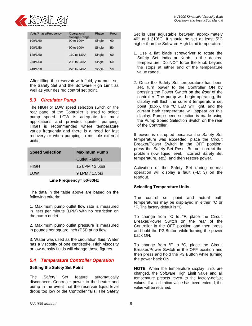
The use of an extension cord is not recommended. However, if one is necessary, it must be properly grounded and capable of handling the total wattage of the unit. The extension cord must not cause more than a 10% drop in voltage to the Circulator. Once the unit has been connected to an appropriate electrical outlet, place the Circuit Breaker/Power Switch on the rear of the Controller in the ON position. Four decimal points (….) will appear on the digital display. DO NOT place the Power Switch on the front of the Controller ON until the Safety Set has been adjusted to the desired temperature. Indicated Voltage
KV1000 Kinematic Viscosity Bath Operation and Instruction Manual
KV1000-Manual -9-
Volts/Phase/Frequency Operational Voltage Range
Phase Freq.
100/1/60 90 to 100V Single 60
100/1/50 90 to 100V Single 50
120/1/60 110 to 130V Single 60
230/1/60 208 to 230V Single 60
240/1/50 220 to 240V Single 50
After filling the reservoir with fluid, you must set the Safety Set and the Software High Limit as well as your desired control set point.
5.3 Circulator Pump
The HIGH or LOW speed selection switch on the rear panel of the Controller is used to select pump speed. LOW is adequate for most applications and provides quieter pumping. HIGH is recommended where temperature varies frequently and there is a need for fast recovery or when pumping to multiple external units.
Speed Selection Maximum Pump
Outlet Ratings
HIGH 15 LPM / 2.6psi
LOW 9 LPM / 1.5psi
Line Frequency= 50-60Hz
The data in the table above are based on the following criteria: 1. Maximum pump outlet flow rate is measured in liters per minute (LPM) with no restriction on the pump outlet 2. Maximum pump outlet pressure is measured in pounds per square inch (PSI) at no flow. 3. Water was used as the circulation fluid. Water has a viscosity of one centistoke. High viscosity or low-density fluids will change these figures.
5.4 Temperature Controller Operation
Setting the Safety Set Point The Safety Set feature automatically disconnects Controller power to the heater and pump in the event that the reservoir liquid level drops too low or the Controller fails. The Safety
Set is user adjustable between approximately 40° and 210°C. It should be set at least 5°C higher than the Software High Limit temperature.
1. Use a flat blade screwdriver to rotate the Safety Set Indicator Knob to the desired temperature. Do NOT force the knob beyond the stops at either end of the temperature value range.
2. Once the Safety Set temperature has been set, turn power to the Controller ON by pressing the Power Switch on the front of the controller. The pump will begin operating, the display will flash the current temperature set point (tx.xx), the °C LED will light, and the current bath temperature will appear on this display. Pump speed selection is made using the Pump Speed Selection Switch on the rear of the Controller.
If power is disrupted because the Safety Set temperature was exceeded, place the Circuit Breaker/Power Switch in the OFF position, press the Safety Set Reset Button, correct the problem (low liquid level, incorrect Safety Set temperature, etc.), and then restore power.
Activation of the Safety Set during normal operation will display a fault (FLt 3) on the readout.
Selecting Temperature Units
The control set point and actual bath temperatures may be displayed in either °C or °F. The factory-default is °C.
To change from °C to °F, place the Circuit Breaker/Power Switch on the rear of the Controller in the OFF position and then press and hold the P2 Button while turning the power back ON.
To change from °F to °C, place the Circuit Breaker/Power Switch in the OFF position and then press and hold the P3 Button while turning the power back ON. NOTE: When the temperature display units are changed, the Software High Limit value and all temperature presets revert to the factory-default values. If a calibration value has been entered, the value will be retained.
KV1000 Kinematic Viscosity Bath Operation and Instruction Manual
KV1000-Manual -10-
Setting the Software High Limit This feature provides additional safety and protection by allowing a selectable upper temperature limit set point. To avoid an unwanted shutdown during regular operation, the high limit value should be set at least 5°C higher than the selected control temperature
1. To set the Software High Limit temperature set point, press the P2 and P3 keys simultaneously and repeat until (Hxxx) appears on the display. This is the current Software High Limit value. It is factory set at 152°C.
2. To change the displayed value, press and turn the Select/Set Knob until the desired Software High Limit set point value is displayed. A clockwise rotation increases the value; a counterclockwise rotation decreases the value. Press the Select/Set Knob a second time to accept the new value and return to normal operation.
If the Software High Limit value meets or exceeds the control temperature set point, (EH1) will flash on the display. If this occurs, enter a higher value for the Software High Limit or reduce the control temperature set point.
If the actual bath temperature reaches the Software High Limit Set Point, (FLt1) will flash on the display. Should this occur, the Controller will automatically remove power from the heater. The pump will continue to operate.
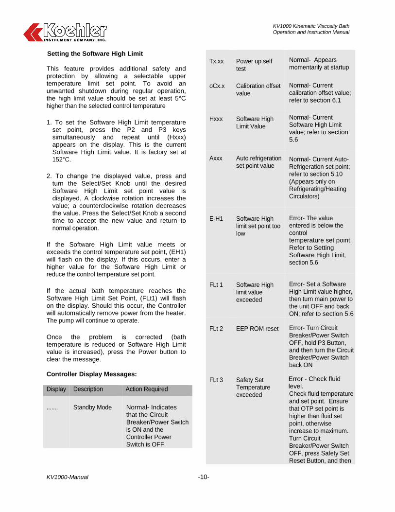
Once the problem is corrected (bath temperature is reduced or Software High Limit value is increased), press the Power button to clear the message. Controller Display Messages: Display Description Action Required
.......
Standby Mode
Normal- Indicates that the Circuit Breaker/Power Switch is ON and the Controller Power Switch is OFF
Tx.xx
Power up self test
Normal- Appears momentarily at startup
oCx.x
Calibration offset value
Normal- Current calibration offset value; refer to section 6.1
Hxxx
Software High Limit Value
Normal- Current Software High Limit value; refer to section 5.6
Axxx
Auto refrigeration set point value
Normal- Current Auto-Refrigeration set point; refer to section 5.10 (Appears only on Refrigerating/Heating Circulators)
E-H1
Software High limit set point too low
Error- The value entered is below the control temperature set point. Refer to Setting Software High Limit, section 5.6
FLt 1
Software High limit value exceeded
Error- Set a Software High Limit value higher, then turn main power to the unit OFF and back ON; refer to section 5.6
FLt 2
EEP ROM reset Error- Turn Circuit
Breaker/Power Switch OFF, hold P3 Button, and then turn the Circuit Breaker/Power Switch back ON
FLt 3
Safety Set Temperature exceeded
Error - Check fluid level. Check fluid temperature and set point. Ensure that OTP set point is higher than fluid set point, otherwise increase to maximum. Turn Circuit Breaker/Power Switch OFF, press Safety Set Reset Button, and then
KV1000 Kinematic Viscosity Bath Operation and Instruction Manual
KV1000-Manual -11-
turn the Circuit Breaker/Power Switch back ON
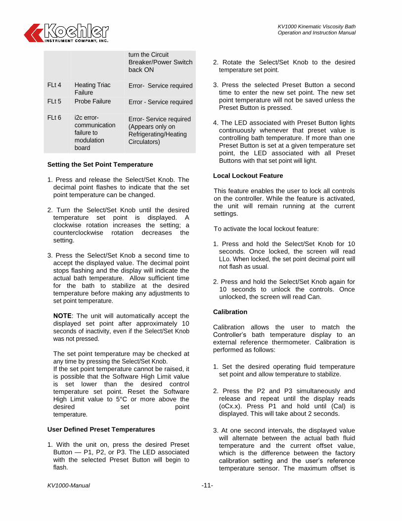
FLt 4 Heating Triac Failure
Error- Service required
FLt 5 Probe Failure Error - Service required
FLt 6 i2c error- communication failure to modulation board
Error- Service required (Appears only on Refrigerating/Heating Circulators)
Setting the Set Point Temperature 1. Press and release the Select/Set Knob. The
decimal point flashes to indicate that the set point temperature can be changed.
2. Turn the Select/Set Knob until the desired
temperature set point is displayed. A clockwise rotation increases the setting; a counterclockwise rotation decreases the setting.
3. Press the Select/Set Knob a second time to
accept the displayed value. The decimal point stops flashing and the display will indicate the actual bath temperature. Allow sufficient time for the bath to stabilize at the desired temperature before making any adjustments to set point temperature.
NOTE: The unit will automatically accept the displayed set point after approximately 10 seconds of inactivity, even if the Select/Set Knob was not pressed. The set point temperature may be checked at any time by pressing the Select/Set Knob. If the set point temperature cannot be raised, it is possible that the Software High Limit value is set lower than the desired control temperature set point. Reset the Software High Limit value to 5°C or more above the desired set point temperature.
User Defined Preset Temperatures
1. With the unit on, press the desired Preset
Button — P1, P2, or P3. The LED associated with the selected Preset Button will begin to flash.
2. Rotate the Select/Set Knob to the desired
temperature set point. 3. Press the selected Preset Button a second
time to enter the new set point. The new set point temperature will not be saved unless the Preset Button is pressed.
4. The LED associated with Preset Button lights
continuously whenever that preset value is controlling bath temperature. If more than one Preset Button is set at a given temperature set point, the LED associated with all Preset Buttons with that set point will light.
Local Lockout Feature This feature enables the user to lock all controls on the controller. While the feature is activated, the unit will remain running at the current settings. To activate the local lockout feature: 1. Press and hold the Select/Set Knob for 10
seconds. Once locked, the screen will read LLo. When locked, the set point decimal point will not flash as usual.
2. Press and hold the Select/Set Knob again for
10 seconds to unlock the controls. Once unlocked, the screen will read Can.
Calibration Calibration allows the user to match the Controller’s bath temperature display to an external reference thermometer. Calibration is performed as follows:
1. Set the desired operating fluid temperature set point and allow temperature to stabilize.
2. Press the P2 and P3 simultaneously and release and repeat until the display reads (oCx.x). Press P1 and hold until (Cal) is displayed. This will take about 2 seconds.
3. At one second intervals, the displayed value will alternate between the actual bath fluid temperature and the current offset value, which is the difference between the factory calibration setting and the user’s reference temperature sensor. The maximum offset is
KV1000 Kinematic Viscosity Bath Operation and Instruction Manual
KV1000-Manual -12-
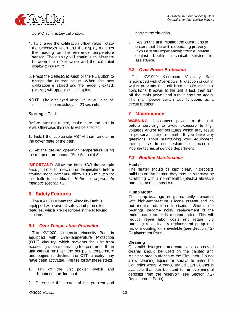
0.9C from factory calibration.
4. To change the calibration offset value, rotate the Select/Set Knob until the display matches the reading on the reference temperature sensor. The display will continue to alternate between the offset value and the calibrated display temperature.
5. Press the Select/Set Knob or the P1 Button to accept the entered value. When the new calibration is stored and the mode is exited, (DONE) will appear on the display.
NOTE: The displayed offset value will also be accepted if there no activity for 20 seconds. Starting a Test Before running a test, make sure the unit is level. Otherwise, the results will be affected. 1. Install the appropriate ASTM thermometer in the cover plate of the bath. 2. Set the desired operation temperature using the temperature control (See Section 4.3).
IMPORTANT: Allow the bath AND the sample enough time to reach the temperature before starting measurements. Allow 10-15 minutes for the bath to equilibrate. Refer to appropriate methods (Section 1.2).
6 Safety Features
The KV1000 Kinematic Viscosity Bath is equipped with several safety and protection features, which are described in the following sections.
6.1 Over Temperature Protection
The KV1000 Kinematic Viscosity Bath is equipped with Over-temperature Protection (OTP) circuitry, which prevents the unit from exceeding unsafe operating temperatures. If the unit cannot maintain the set point temperature and begins to decline, the OTP circuitry may have been activated. Please follow these steps.
1. Turn off the unit power switch and disconnect the line cord.
2. Determine the source of the problem and
correct the situation
3. Restart the unit. Monitor the operations to ensure that the unit is operating properly. If you are still experiencing trouble, please contact Koehler technical service for assistance.
6.2 Over Power Protection
The KV1000 Kinematic Viscosity Bath is equipped with Over-power Protection circuitry, which prevents the unit from unsafe electrical conditions. If power to the unit is lost, then turn off the main power and turn it back on again. The main power switch also functions as a circuit breaker.
7 Maintenance
WARNING. Disconnect power to the unit before servicing to avoid exposure to high voltages and/or temperatures which may result in personal injury or death. If you have any questions about maintaining your equipment, then please do not hesitate to contact the Koehler technical service department.
7.3 Routine Maintenance
Heater The heater should be kept clean. If deposits build up on the heater, they may be removed by scrubbing with a non-metallic (plastic) abrasive pad. Do not use steel wool. Pump Motor The pump bearings are permanently lubricated with high-temperature silicone grease and do not require additional lubrication. Should the bearings become noisy, replacement of the entire pump motor is recommended. This will reduce repair labor costs and retain fluid pumping reliability. A replacement pump and motor mounting kit is available (see Section 7.2- Replacement Parts).
Cleaning Only mild detergents and water or an approved cleaner should be used on the painted and stainless steel surfaces of the Circulator. Do not allow cleaning liquids or sprays to enter the Controller vents. A concentrated bath cleaner is available that can be used to remove mineral deposits from the reservoir (see Section 7.2-Replacement Parts).
KV1000 Kinematic Viscosity Bath Operation and Instruction Manual
KV1000-Manual -13-
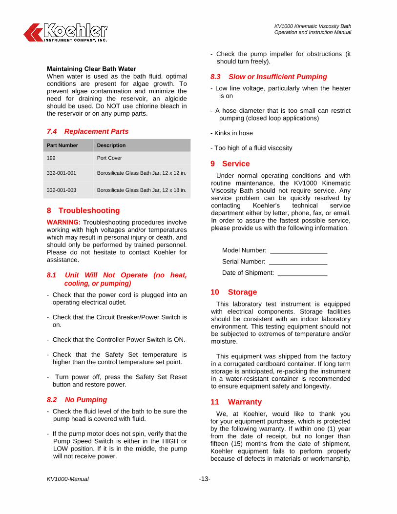
Maintaining Clear Bath Water When water is used as the bath fluid, optimal conditions are present for algae growth. To prevent algae contamination and minimize the need for draining the reservoir, an algicide should be used. Do NOT use chlorine bleach in the reservoir or on any pump parts.
7.4 Replacement Parts
Part Number Description
199 Port Cover
332-001-001 Borosilicate Glass Bath Jar, 12 x 12 in.
332-001-003 Borosilicate Glass Bath Jar, 12 x 18 in.
8 Troubleshooting
WARNING: Troubleshooting procedures involve working with high voltages and/or temperatures which may result in personal injury or death, and should only be performed by trained personnel. Please do not hesitate to contact Koehler for assistance.
8.1 Unit Will Not Operate (no heat, cooling, or pumping)
- Check that the power cord is plugged into an operating electrical outlet.
- Check that the Circuit Breaker/Power Switch is
on. - Check that the Controller Power Switch is ON. - Check that the Safety Set temperature is
higher than the control temperature set point. - Turn power off, press the Safety Set Reset
button and restore power.
8.2 No Pumping
- Check the fluid level of the bath to be sure the pump head is covered with fluid.
- If the pump motor does not spin, verify that the
Pump Speed Switch is either in the HIGH or LOW position. If it is in the middle, the pump will not receive power.
- Check the pump impeller for obstructions (it should turn freely).
8.3 Slow or Insufficient Pumping
- Low line voltage, particularly when the heater is on
- A hose diameter that is too small can restrict
pumping (closed loop applications) - Kinks in hose - Too high of a fluid viscosity
9 Service
Under normal operating conditions and with routine maintenance, the KV1000 Kinematic Viscosity Bath should not require service. Any service problem can be quickly resolved by contacting Koehler’s technical service department either by letter, phone, fax, or email. In order to assure the fastest possible service, please provide us with the following information.
Model Number:
Serial Number:
Date of Shipment:
10 Storage
This laboratory test instrument is equipped with electrical components. Storage facilities should be consistent with an indoor laboratory environment. This testing equipment should not be subjected to extremes of temperature and/or moisture.
This equipment was shipped from the factory
in a corrugated cardboard container. If long term storage is anticipated, re-packing the instrument in a water-resistant container is recommended to ensure equipment safety and longevity.
11 Warranty
We, at Koehler, would like to thank you for your equipment purchase, which is protected by the following warranty. If within one (1) year from the date of receipt, but no longer than fifteen (15) months from the date of shipment, Koehler equipment fails to perform properly because of defects in materials or workmanship,
KV1000 Kinematic Viscosity Bath Operation and Instruction Manual
KV1000-Manual -14-
Koehler Instrument Company, Inc. will repair or, at its sole discretion, replace the equipment without charge F.O.B. its plant, provided the equipment has been properly installed, operated, and maintained. Koehler Instrument Company must be advised in writing of the malfunction and authorize the return of the product to the factory. The sole responsibility of Koehler Instrument Company and the purchaser’s exclusive remedy for any claim arising out of the purchase of any product is the repair or replacement of the product. In no event shall the cost of the purchaser’s remedy exceed the purchase price, nor shall Koehler Instrument Company be liable for any special, indirect, incidental, consequential, or exemplary damages. KOEHLER INSTRUMENT COMPANY, INC. DISCLAIMS ALL OTHER WARRANTIES, EXPRESSED OR IMPLIED, INCLUDING ANY IMPLIED WARRANTIES OF FITNESS FOR A PARTICULAR PURPOSE. Please save the shipping carton in the event the equipment needs to be returned to the factory for warranty repair. If the carton is discarded, it will be the purchaser’s responsibility to provide an appropriate shipping carton.
12 Returned Goods Policy
To return products for credit or replacement, please contact Koehler Customer Service with your purchase order number, our packing list/invoice number, the item(s) to be returned and the reason for the return. You will be issued a Returned Authorization (RA) number, which must be prominently displayed on the shipping container when you return the material to our plant. Shipping containers without an RA number prominently displayed with will be returned to the sender. Goods must be returned freight prepaid. Returns will be subject to a restocking charge, the application of which will depend upon the circumstances necessitating the return. Some returns cannot be authorized, including certain products purchased from outside vendors for the convenience of the customer, products manufactured on special order, products shipped from the factory past ninety (90) days, and products which have been used or modified in such a way that they cannot be returned to stock for future sale.

KV1000 Kinematic Viscosity Bath Operation and Instruction Manual
KV1000-Manual -15-
Notes
KV1000 Kinematic Viscosity Bath Operation and Instruction Manual
KV1000-Manual -16-
Notes