Embed Size (px)
Citation preview

I N S P E C T I N G A N D E V A L U A T I N G S O I L
T R E A T M E N T S Y S T E M S & R E M E D I A T I O N
S A R A H E G E R
U N I V E R S I T Y O F M I N N E S O T A
S H E G E R @ U M N . E D U
W W W . S E P T I C . U M N . E D U
PRESENTATION OVERVIEW
• Evaluating soil treatment system
• Excessive ponding– Causes
– Potential solutions
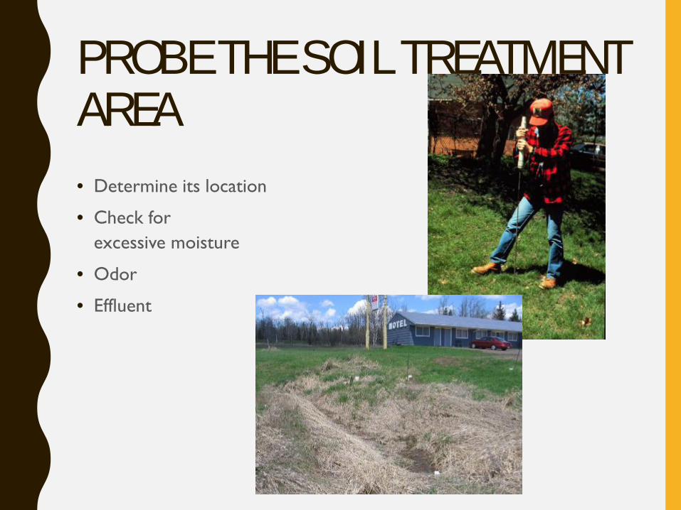
PROBE THE SOIL TREATMENT AREA• Determine its location
• Check for excessive moisture
• Odor
• Effluent
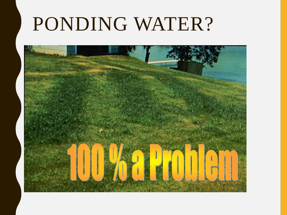
PONDING WATER?
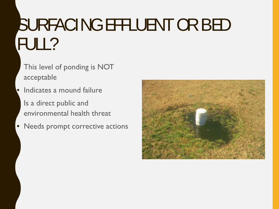
SURFACING EFFLUENT OR BED FULL?• This level of ponding is NOT
acceptable
• Indicates a mound failure
• Is a direct public and environmental health threat
• Needs prompt corrective actions

LUSH VEGETATION?• Green grass – isn’t lush
• Cattails?
• Change?
DYE TEST• Can expose obvious leaks • Procedure
– Dye is flushed down a toilet – The amount of dye determined by the size of the septic tank
• Larger septic tank will require that more dye
• In most cases, several ounces of concentrated dye solution is adequate for a test
– Water is run into the system with a faucet to flush the dye into the septic tank, and then into the soil
• Volume of water introduced to the system is determined by the size of the tank
• The objective is to flood the absorption area with water containing the dye solution
• No dye should be present at the surface
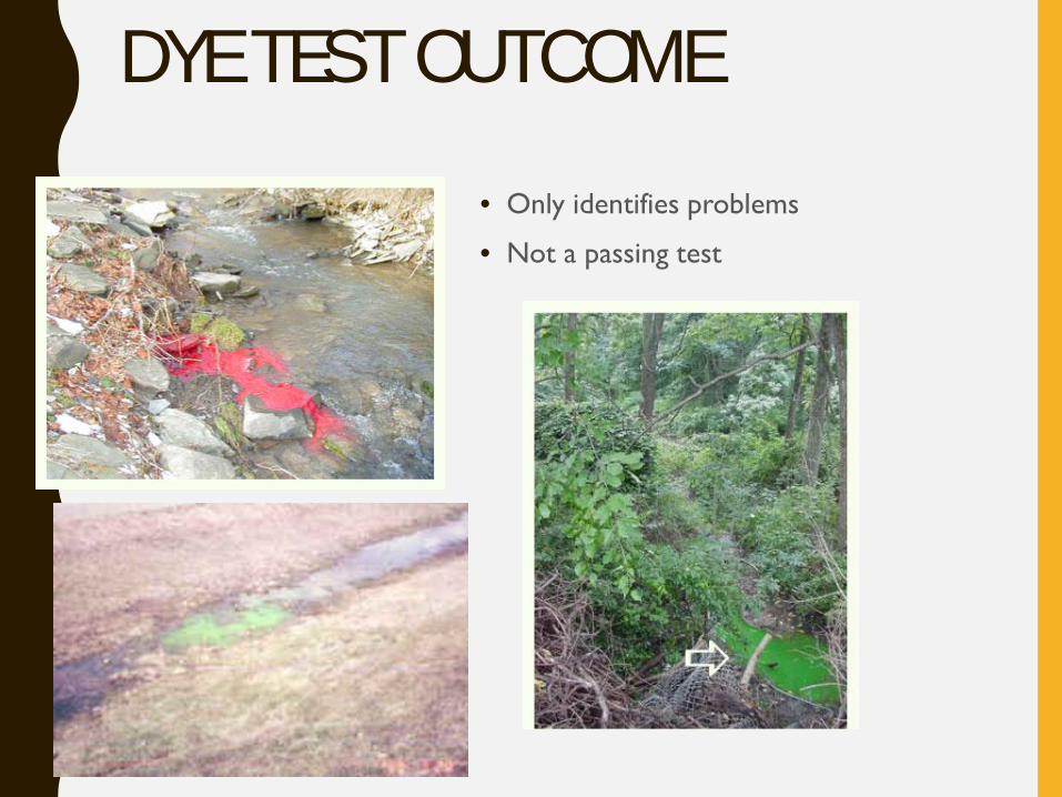
DYE TEST OUTCOME• Only identifies problems
• Not a passing test
CORRECT SYSTEM INSTALLED?• Does the system have separation to the limiting condition
– Redox features/mottles
– Bedrock
– Hardpans
• Is the system the right size for building and soil conditions
– Gallons per day
– Loading rate
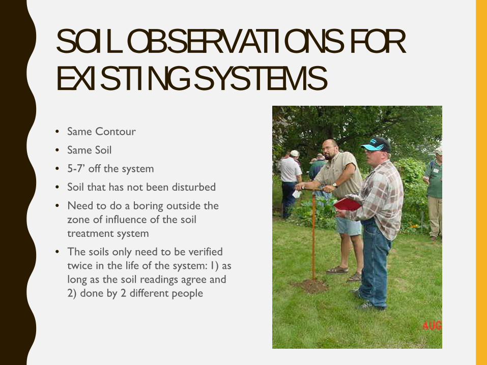
SOIL OBSERVATIONS FOR EXISTING SYSTEMS• Same Contour
• Same Soil
• 5-7’ off the system
• Soil that has not been disturbed
• Need to do a boring outside the zone of influence of the soil treatment system
• The soils only need to be verified twice in the life of the system: 1) as long as the soil readings agree and 2) done by 2 different people
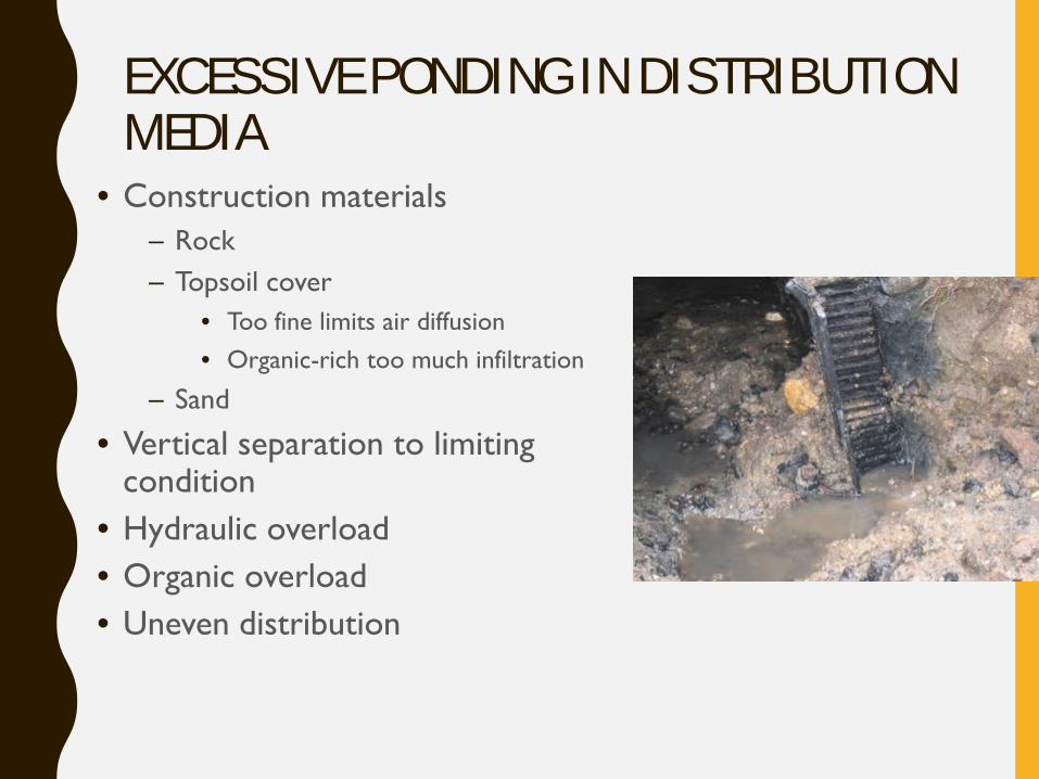
EXCESSIVE PONDING IN DISTRIBUTION MEDIA
• Construction materials– Rock– Topsoil cover
• Too fine limits air diffusion• Organic-rich too much infiltration
– Sand
• Vertical separation to limiting condition
• Hydraulic overload• Organic overload• Uneven distribution
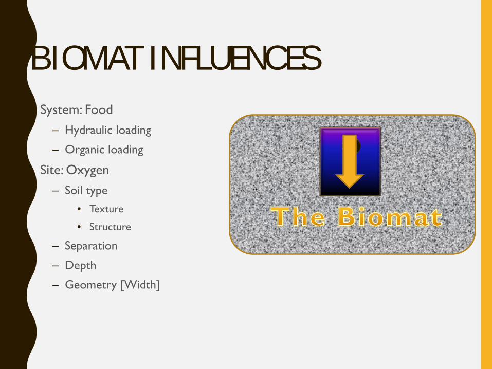
BIOMAT INFLUENCES• System: Food
– Hydraulic loading
– Organic loading
• Site: Oxygen– Soil type
• Texture
• Structure
– Separation
– Depth
– Geometry [Width]
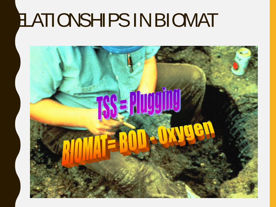
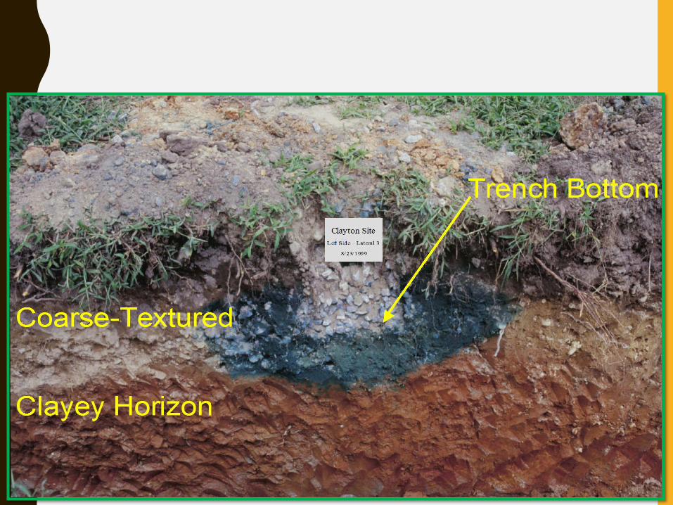
RELATIONSHIPS IN BIOMAT
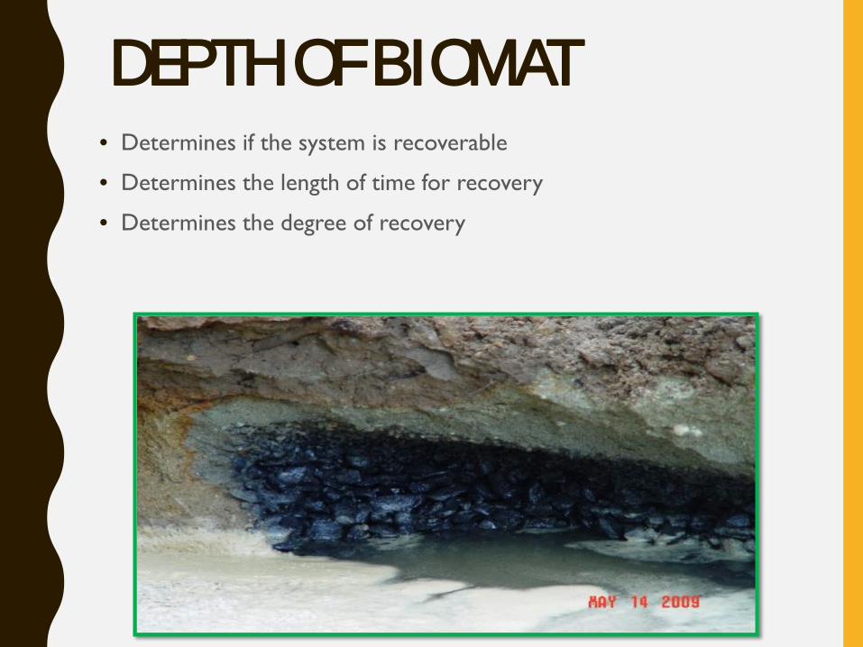
DEPTH OF BIOMAT• Determines if the system is recoverable
• Determines the length of time for recovery
• Determines the degree of recovery
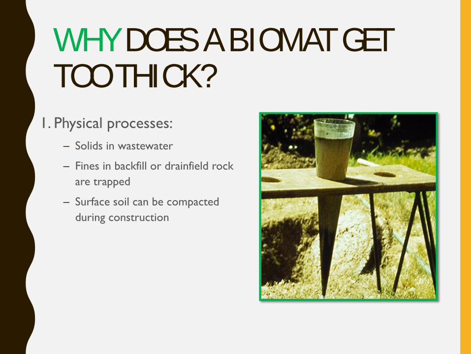
WHY DOES A BIOMAT GET TOO THICK?
1. Physical processes: – Solids in wastewater
– Fines in backfill or drainfield rock are trapped
– Surface soil can be compacted during construction
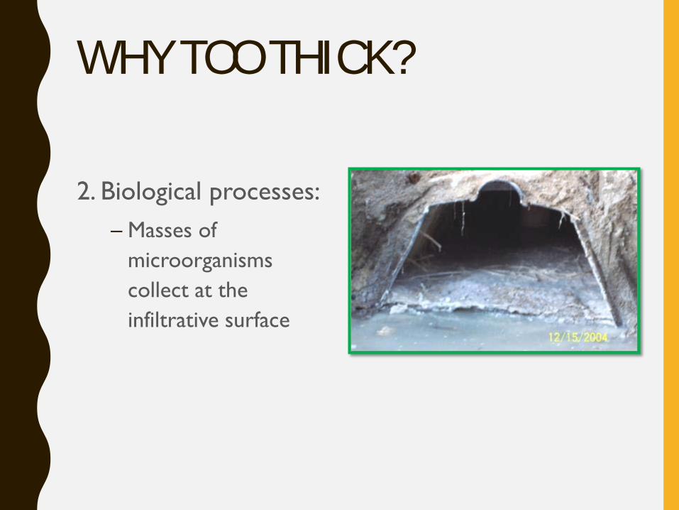
WHY TOO THICK?
2. Biological processes:– Masses of
microorganisms collect at the infiltrative surface
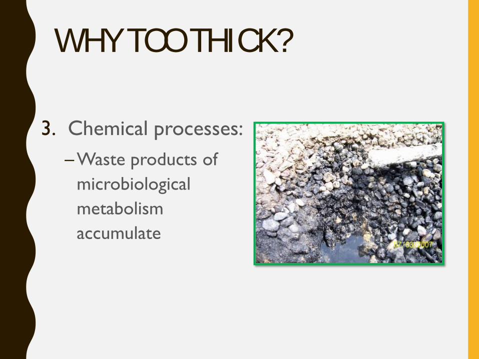
WHY TOO THICK?
3. Chemical processes:– Waste products of
microbiological metabolism accumulate
Picture of surfacing
WHAT IS REMEDIATION?
• Remediation is defined as the act or process of correcting a fault or deficiency in a system without changing system structure or form
• Consortium of Institutes for Decentralized Wastewater Treatment (2009)
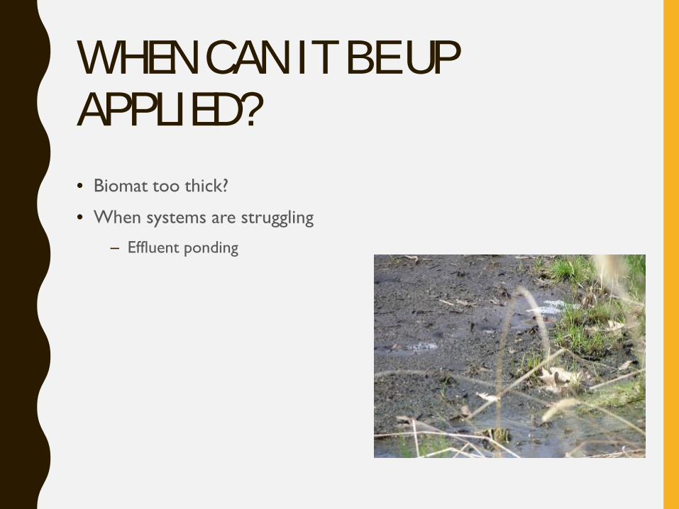
WHEN CAN IT BE UP APPLIED?• Biomat too thick?
• When systems are struggling
– Effluent ponding
IDENTIFYING THE PROBLEMS & SOLUTIONS• Determine factors that contributed to failure
• Need to check them all
• Need to fix them all
• Be careful
• Troubleshooting checklist on our website
FAILURE ANALYSIS CHECKLIST• Number of occupants
– Adults, teenagers, children
• Medical conditions and medicine use
• Use of cleaners, chemicals and other antimicrobials
• In-home businesses
• Clean water additions
FAILURE ANALYSIS CHECKLIST
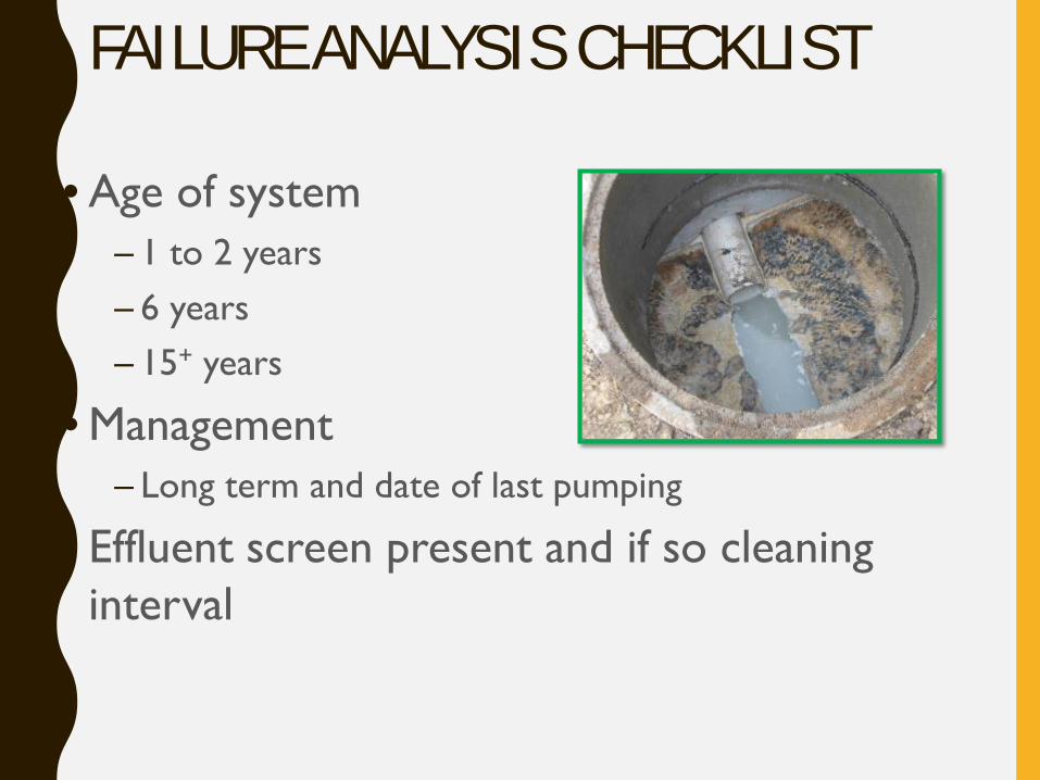
• Age of system– 1 to 2 years– 6 years– 15+ years
• Management – Long term and date of last pumping
• Effluent screen present and if so cleaning interval
FAILURE ANALYSIS PROCEDURE • Review of:
– The permit - system design, system component settings, and system component locations
– Monitoring and maintenance the system has received (or not received) throughout its life
• Determine actual wastewater flow:
– Comparison to the design values
– Hydraulic loading rate
– Organic loading rates
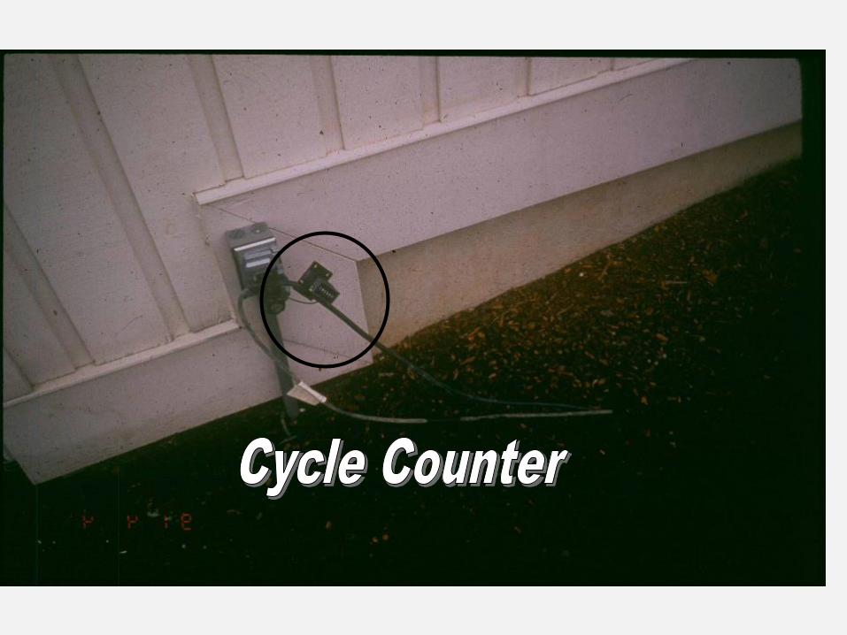
MEASURING ACTUAL FLOWS
• Measuring on pump– Elapsed time meter
– Cycle counter
– Best way
• Water meter– Subject to source water challenges & reading by owner
• Number of people living in home– 75 gallons per person
– Not always accurate
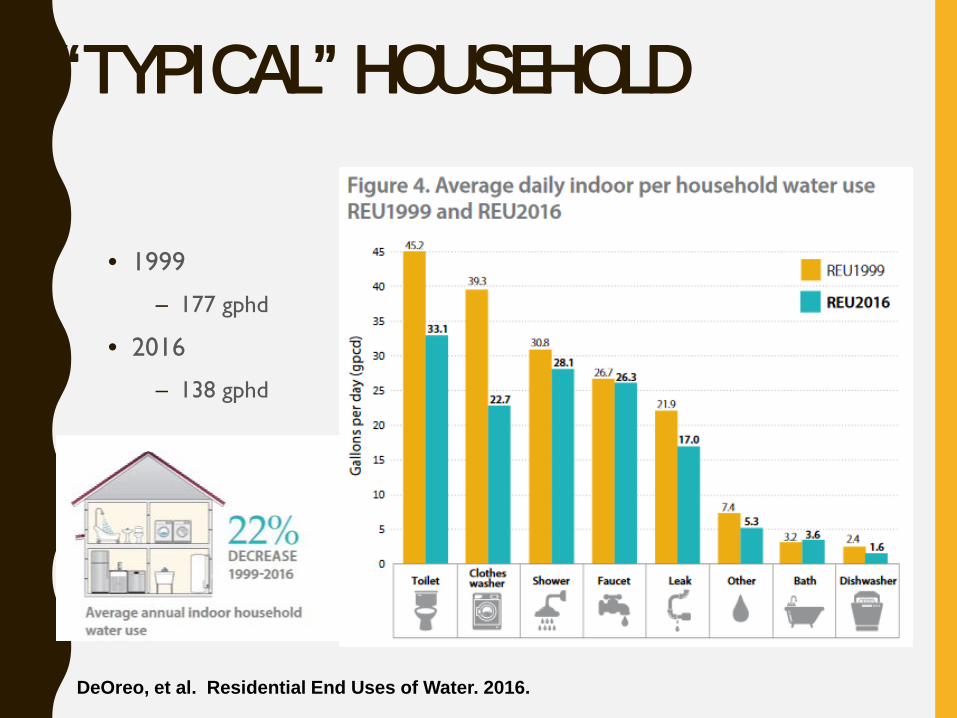
“TYPICAL” HOUSEHOLD
DeOreo, et al. Residential End Uses of Water. 2016.
• 1999
– 177 gphd
• 2016
– 138 gphd
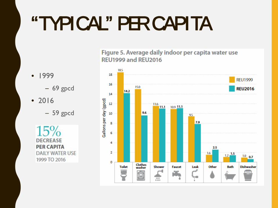
“TYPICAL” PER CAPITA
• 1999
– 69 gpcd
• 2016
– 59 gpcd
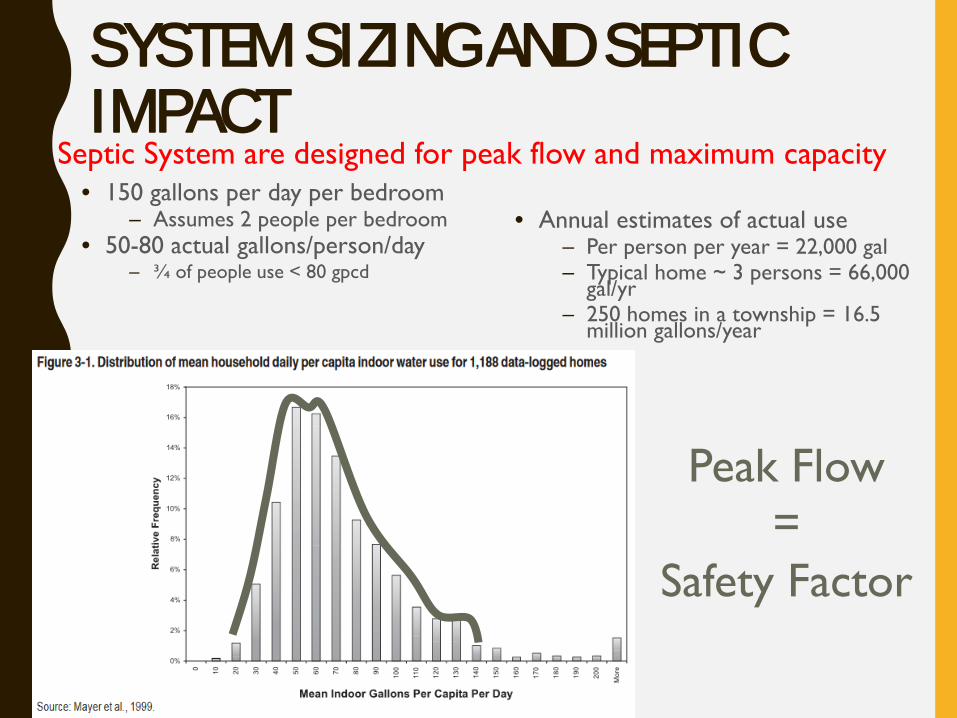
SYSTEM SIZING AND SEPTIC IMPACT
• 150 gallons per day per bedroom– Assumes 2 people per bedroom
• 50-80 actual gallons/person/day– ¾ of people use < 80 gpcd
• Annual estimates of actual use– Per person per year = 22,000 gal– Typical home ~ 3 persons = 66,000
gal/yr– 250 homes in a township = 16.5
million gallons/year
Septic System are designed for peak flow and maximum capacity
Peak Flow=
Safety Factor
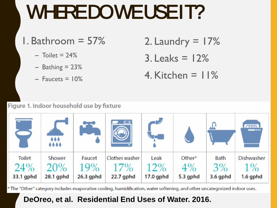
WHERE DO WE USE IT?1. Bathroom = 57%
– Toilet = 24%
– Bathing = 23%
– Faucets = 10%
DeOreo, et al. Residential End Uses of Water. 2016.
2. Laundry = 17%
3. Leaks = 12%
4. Kitchen = 11%
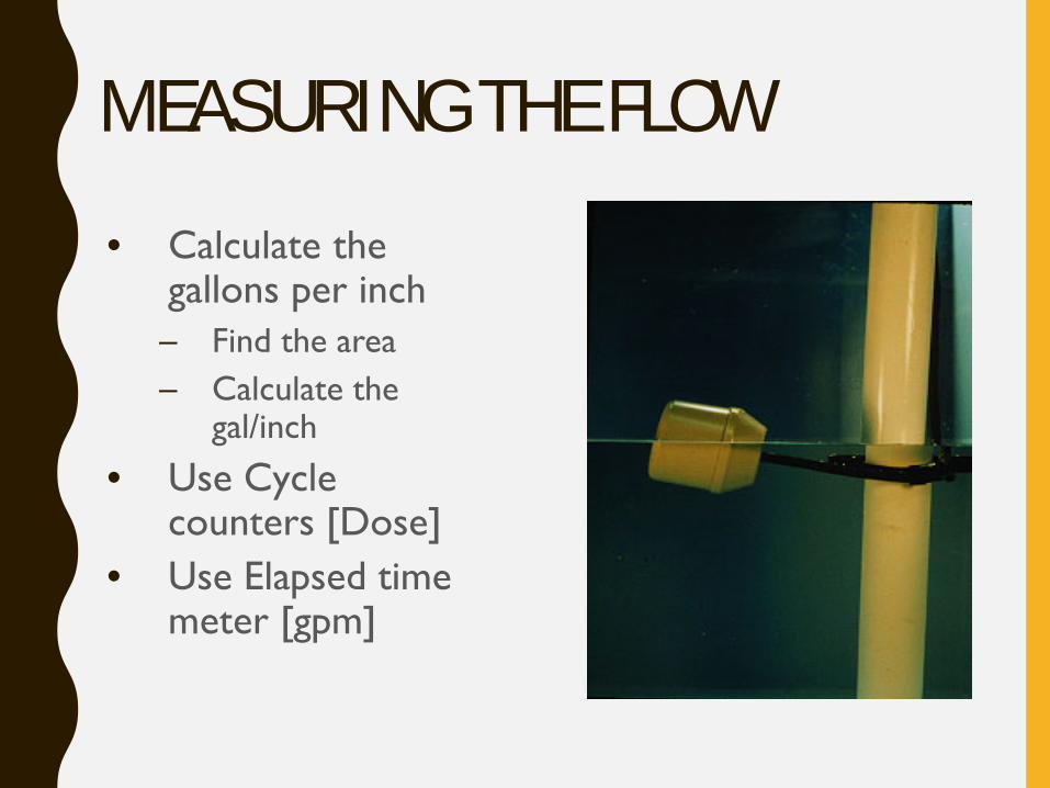
MEASURING THE FLOW• Calculate the
gallons per inch– Find the area– Calculate the
gal/inch
• Use Cycle counters [Dose]
• Use Elapsed time meter [gpm]
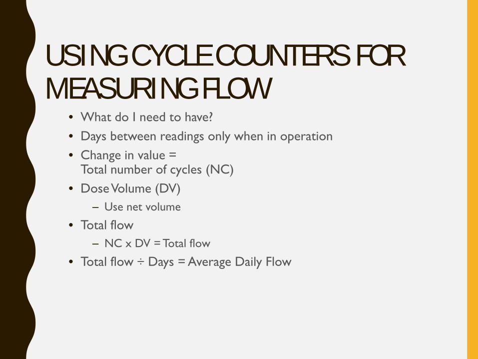
USING CYCLE COUNTERS FOR MEASURING FLOW
• What do I need to have?• Days between readings only when in operation• Change in value =
Total number of cycles (NC)• Dose Volume (DV)
– Use net volume
• Total flow– NC x DV = Total flow
• Total flow ÷ Days = Average Daily Flow
PROCEDURE CONT’D
• 3. Inspect and verify performance of all system components
• 4. Review of the soils to confirm that the soil descriptions in the design are accurate and system is sized appropriately
• 5. Determine of the factor(s) that contributed to the failure
Wastewater Characterization
Field testsTemp. Dissolved Oxygen pH
Laboratory testsBOD5 TSS FOG
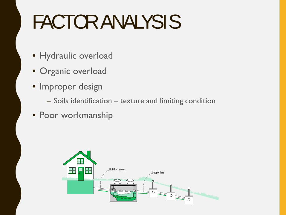
FACTOR ANALYSIS• Hydraulic overload
• Organic overload
• Improper design– Soils identification – texture and limiting condition
• Poor workmanship
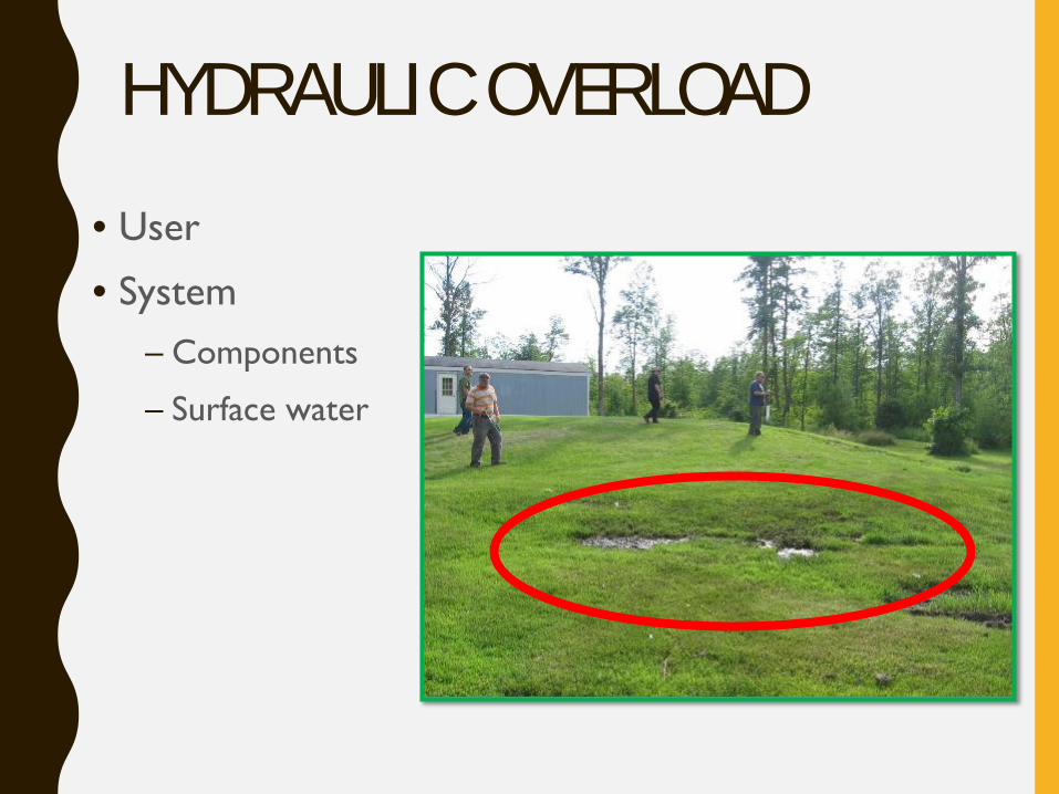
HYDRAULIC OVERLOAD• User
• System– Components
– Surface water
ORGANIC OVERLOAD- HIGH STRENGTH WASTE (HSW)
• National glossary definition of HSW
Effluent from a septic tank or other pretreatment component that has:
BOD5 > 170 mg/L, and/or TSS > 60 mg/L, and/or (FOG) > 25 mg/L and is applied to an
infiltrative surface
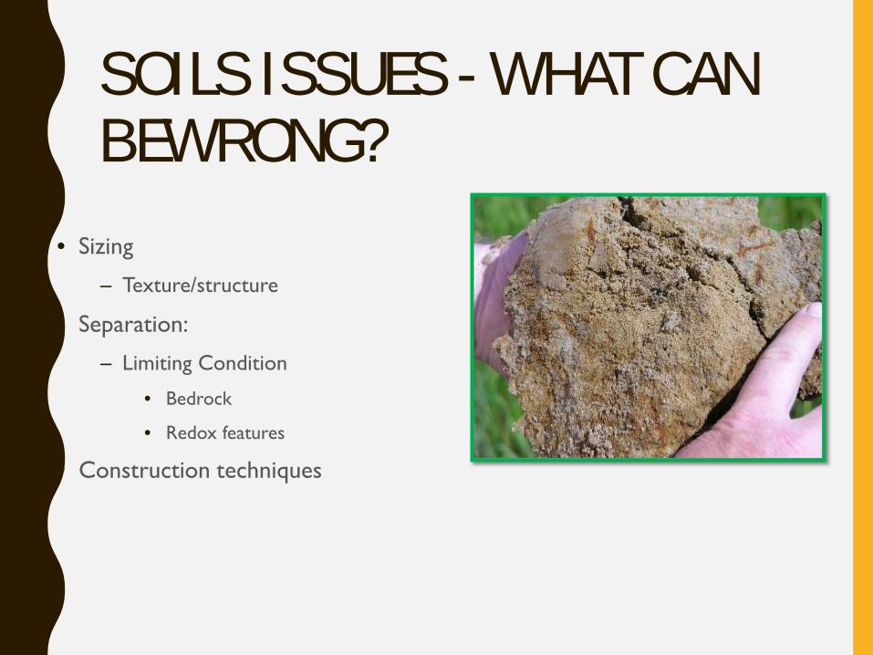
SOILS ISSUES - WHAT CAN BEWRONG?
• Sizing
– Texture/structure
• Separation:
– Limiting Condition
• Bedrock
• Redox features
• Construction techniques
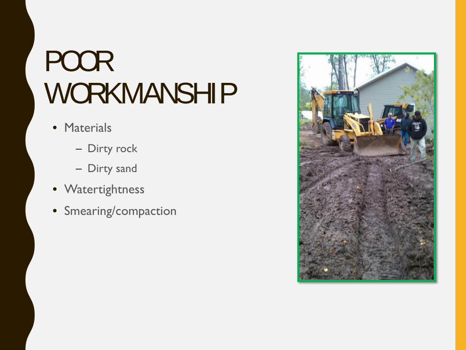
POOR WORKMANSHIP
• Materials
– Dirty rock
– Dirty sand
• Watertightness
• Smearing/compaction
ROCK AND SAND
• Typically must be washed to free of fines (silts and clays)
• Rock should have <1% by weight
• Sand should have < 5% by weight
• More then that causes plugging of pores
WATERTIGHTNESS
• Critical access points:– Inlets/outlets
– Seams
– Risers
• Methods:– Cast in place boots and risers
– Proper application of mastic and other sealants
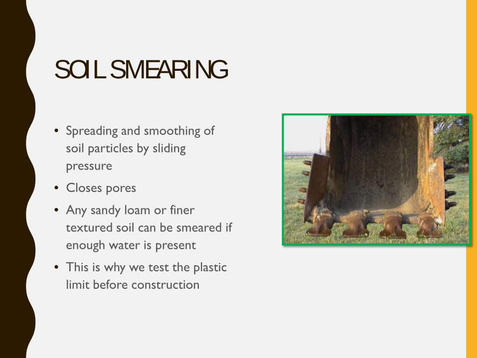
SOIL SMEARING
• Spreading and smoothing of soil particles by sliding pressure
• Closes pores
• Any sandy loam or finer textured soil can be smeared if enough water is present
• This is why we test the plastic limit before construction
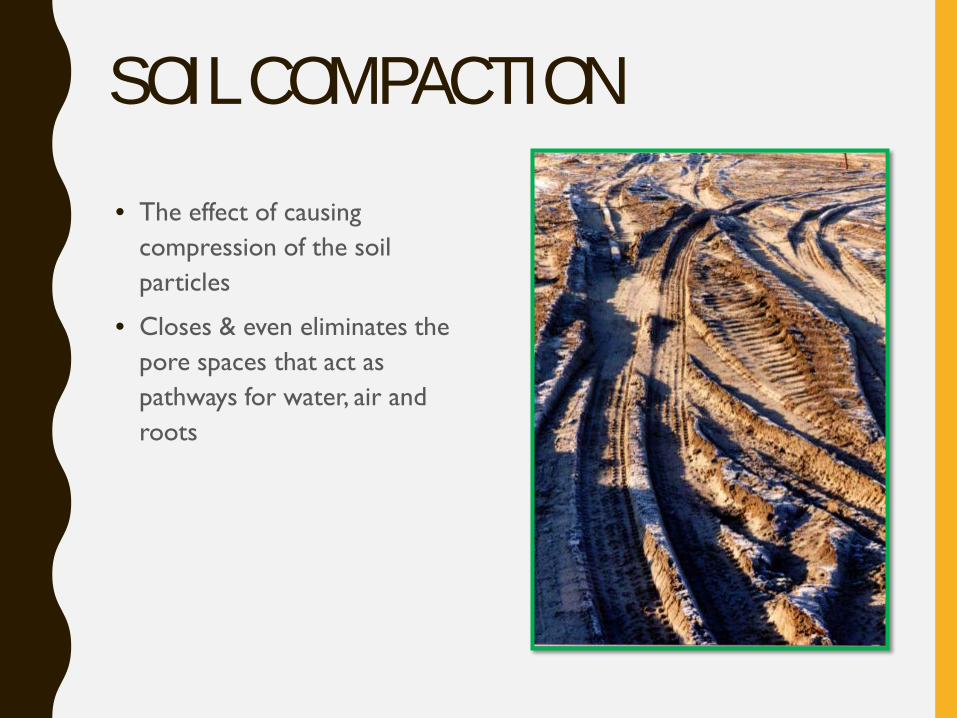
SOIL COMPACTION • The effect of causing
compression of the soil particles
• Closes & even eliminates the pore spaces that act as pathways for water, air and roots
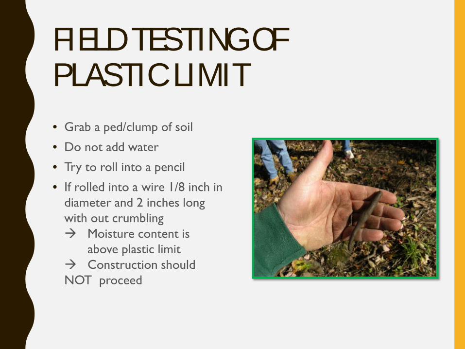
FIELD TESTING OF PLASTIC LIMIT• Grab a ped/clump of soil
• Do not add water
• Try to roll into a pencil
• If rolled into a wire 1/8 inch in diameter and 2 inches long with out crumbling Moisture content is
above plastic limit Construction should NOT proceed
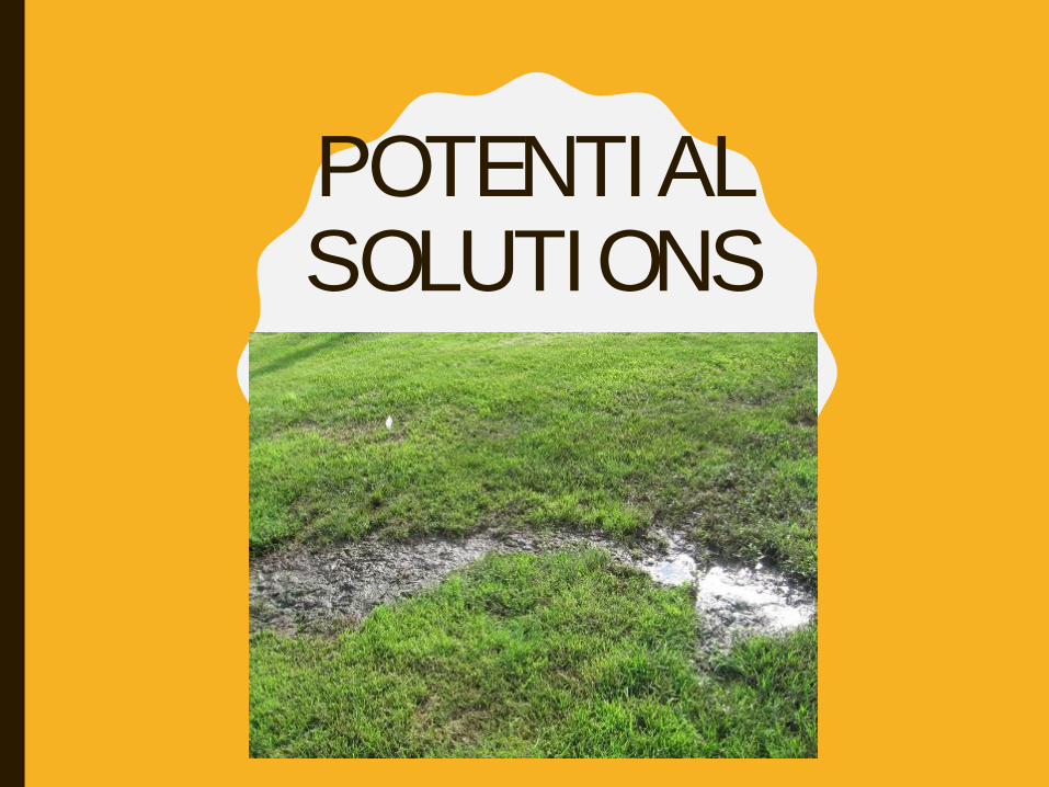
P O T E N T I A L S O L U T I O N S
SOLUTIONS: LOWERING HYDRAULIC LOADING• Reduce usage
– System owner uses less water, eliminate water softener, iron filter, add low flow fixtures and appliances, fix leaky toilets and faucets, etc.
• Time dosing with surge storage
• Holding tank for peak events
FLOW EQUALIZATION SYSTEMS
• Makes the flow introduced to the treatment system more consistent.
• Flow equalization is important if
– The average flow is ≥ 70% of the design capacity
– Water use habits or facility operations are variable- Example church only open on Sun.
– Frequent peaks exceed system capacity
• Wash day: cleaning service
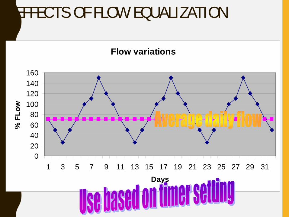
EFFECTS OF FLOW EQUALIZATION
Flow variations
020406080
100120140160
1 3 5 7 9 11 13 15 17 19 21 23 25 27 29 31Days
% F
Low
BENEFITS OF A FLOW EQUALIZATION SYSTEM• Monitoring of flows from the surge tank may help detect
– major changes in flow patterns
– leaking effluent
– clogging orifices
• Provide storage and spread out water delivery after a power outage.
• Regular feeding the hungry population of microbes that are used for treatment.
• Regular resting
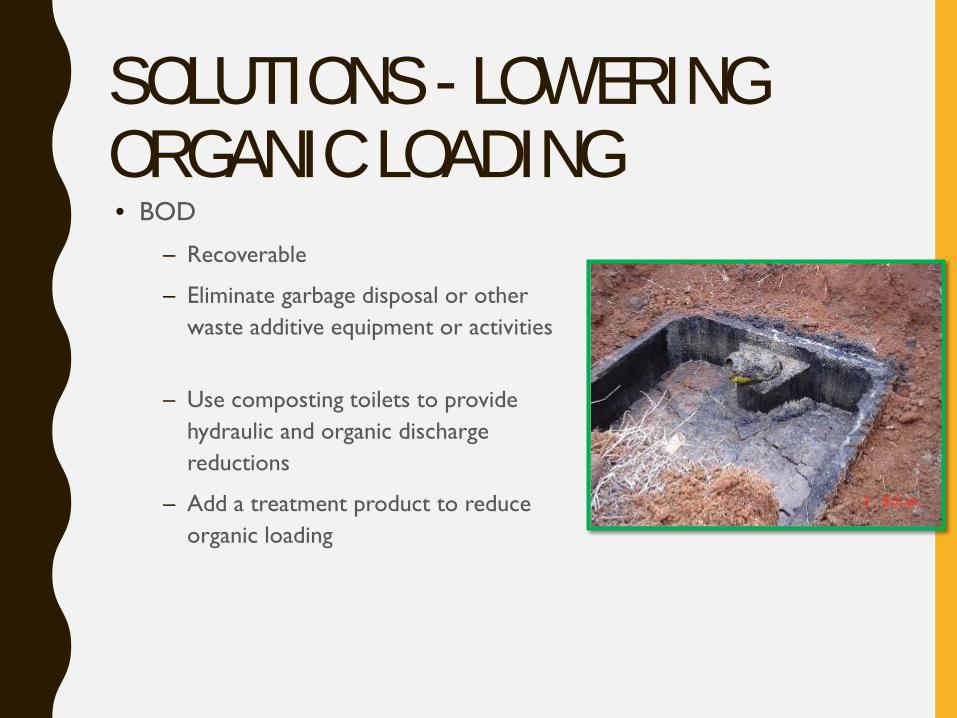
SOLUTIONS - LOWERING ORGANIC LOADING• BOD
– Recoverable
– Eliminate garbage disposal or other waste additive equipment or activities
– Use composting toilets to provide hydraulic and organic discharge reductions
– Add a treatment product to reduce organic loading
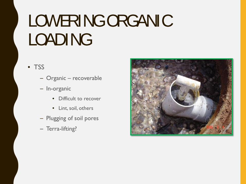
LOWERING ORGANIC LOADING• TSS
– Organic – recoverable
– In-organic
• Difficult to recover
• Lint, soil, others
– Plugging of soil pores
– Terra-lifting?
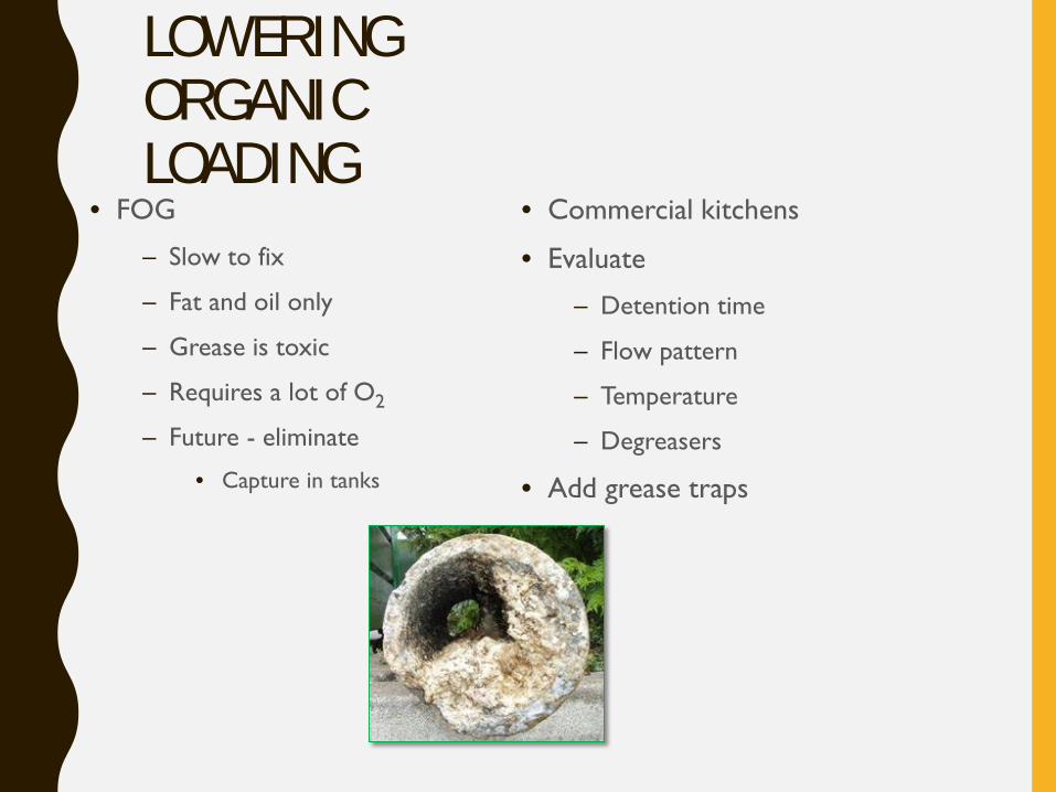
LOWERING ORGANIC LOADING
• FOG
– Slow to fix
– Fat and oil only
– Grease is toxic
– Requires a lot of O2
– Future - eliminate
• Capture in tanks
• Commercial kitchens
• Evaluate
– Detention time
– Flow pattern
– Temperature
– Degreasers
• Add grease traps
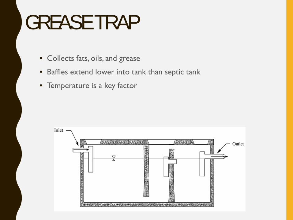
GREASE TRAP• Collects fats, oils, and grease
• Baffles extend lower into tank than septic tank
• Temperature is a key factor
GREASE TRAP• Design
– Minimum of 24 hours (1 day) of hydraulic retention time is recommended, but can be up 4 days or more
– Estimate 70% of total design flow if actual kitchen flows are unavailable
– Outlet baffle should extended to 50 - 70% of liquid depth
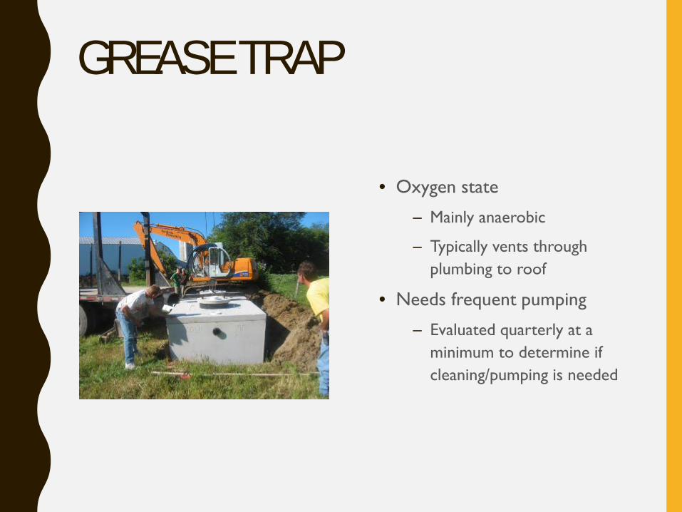
GREASE TRAP
• Oxygen state
– Mainly anaerobic
– Typically vents through plumbing to roof
• Needs frequent pumping
– Evaluated quarterly at a minimum to determine if cleaning/pumping is needed
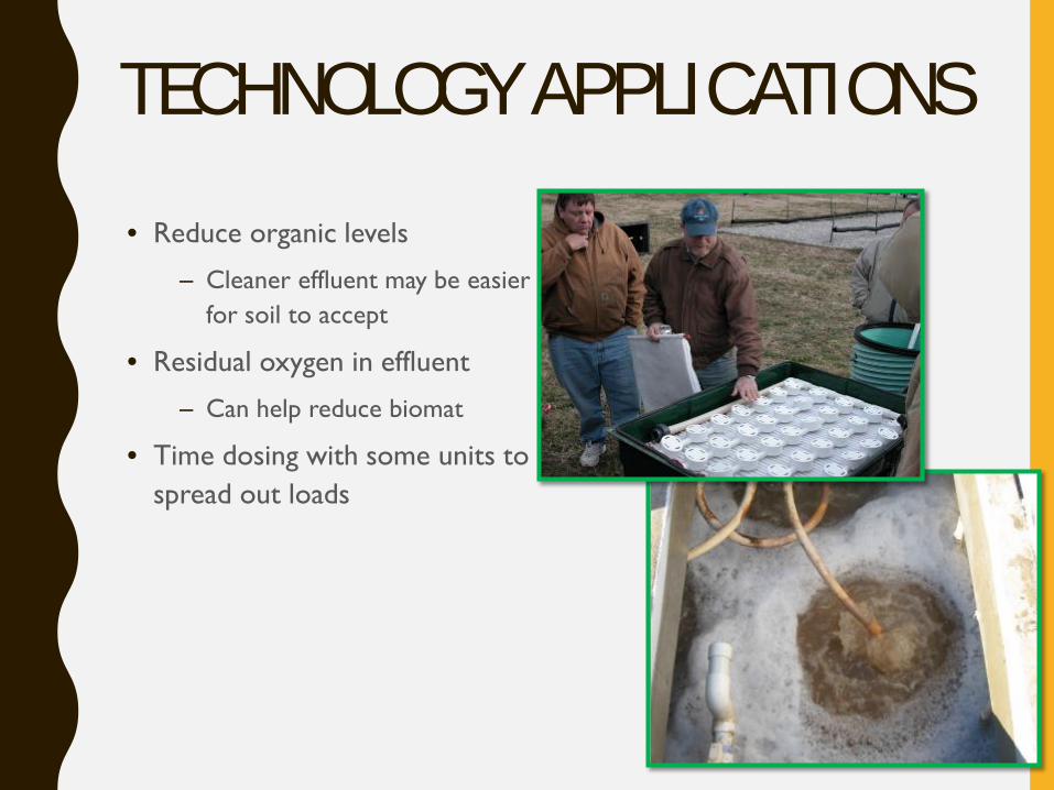
TECHNOLOGY APPLICATIONS• Reduce organic levels
– Cleaner effluent may be easier for soil to accept
• Residual oxygen in effluent
– Can help reduce biomat
• Time dosing with some units to spread out loads
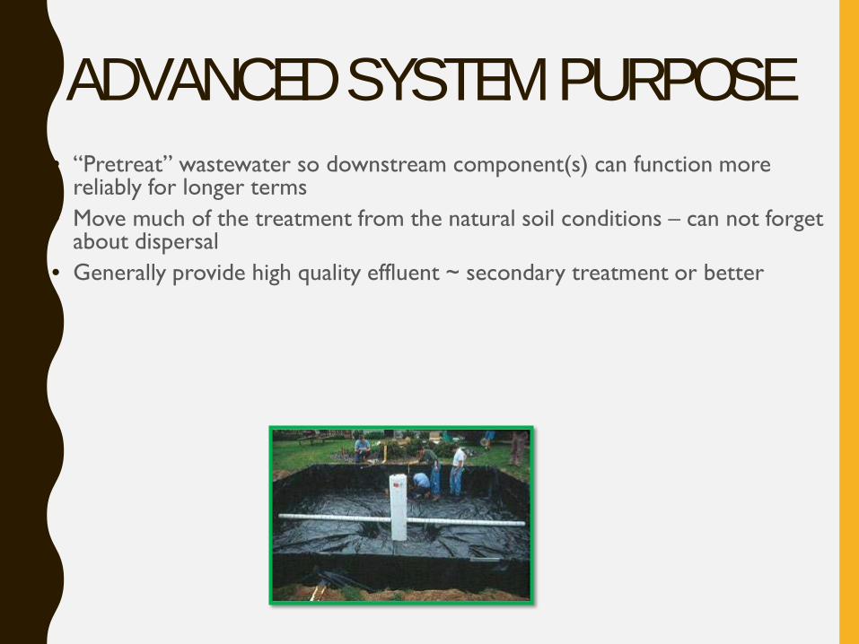
ADVANCED SYSTEM PURPOSE• “Pretreat” wastewater so downstream component(s) can function more
reliably for longer terms• Move much of the treatment from the natural soil conditions – can not forget
about dispersal• Generally provide high quality effluent ~ secondary treatment or better
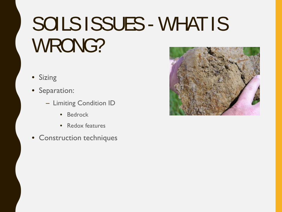
SOILS ISSUES - WHAT IS WRONG?• Sizing
• Separation:
– Limiting Condition ID
• Bedrock
• Redox features
• Construction techniques
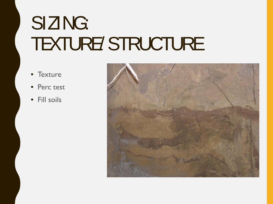
SIZING: TEXTURE/STRUCTURE• Texture
• Perc test
• Fill soils
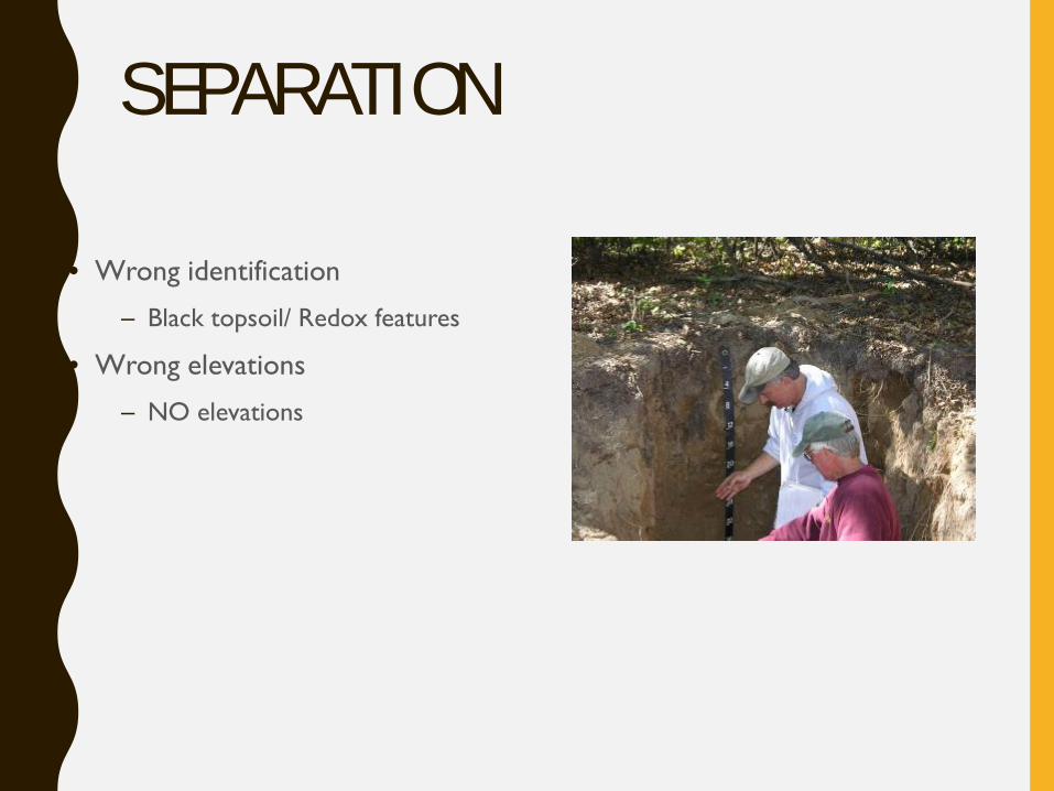
SEPARATION
• Wrong identification
– Black topsoil/ Redox features
• Wrong elevations
– NO elevations
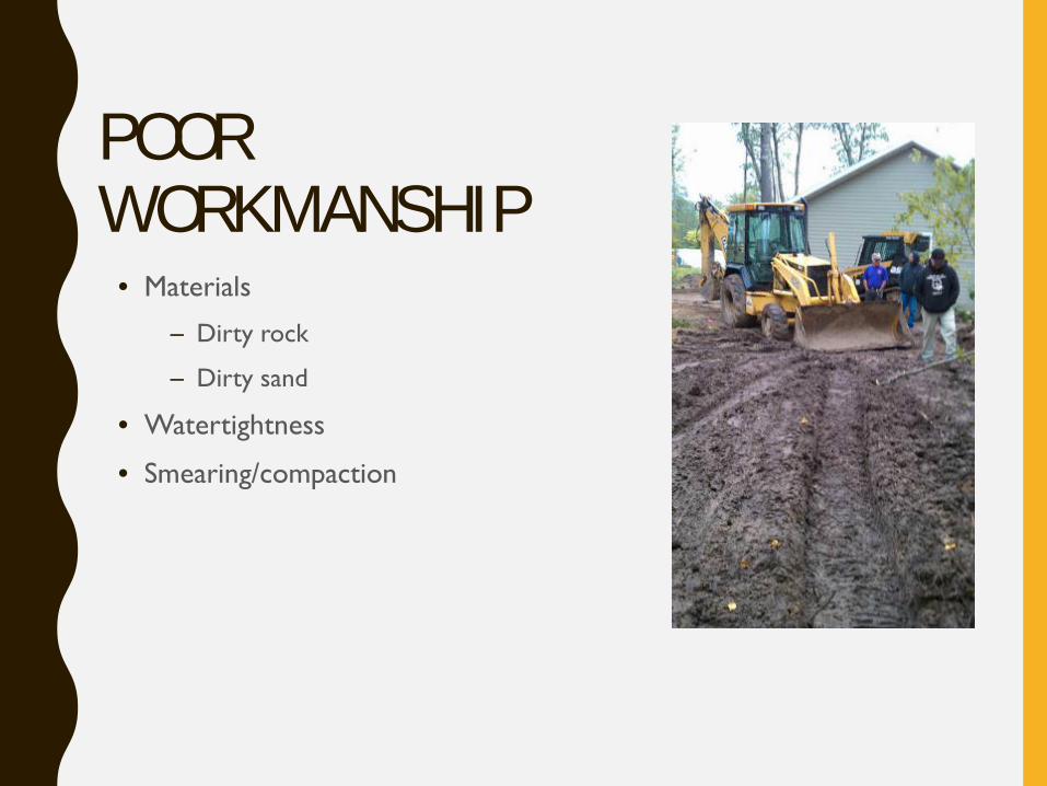
POOR WORKMANSHIP
• Materials
– Dirty rock
– Dirty sand
• Watertightness
• Smearing/compaction
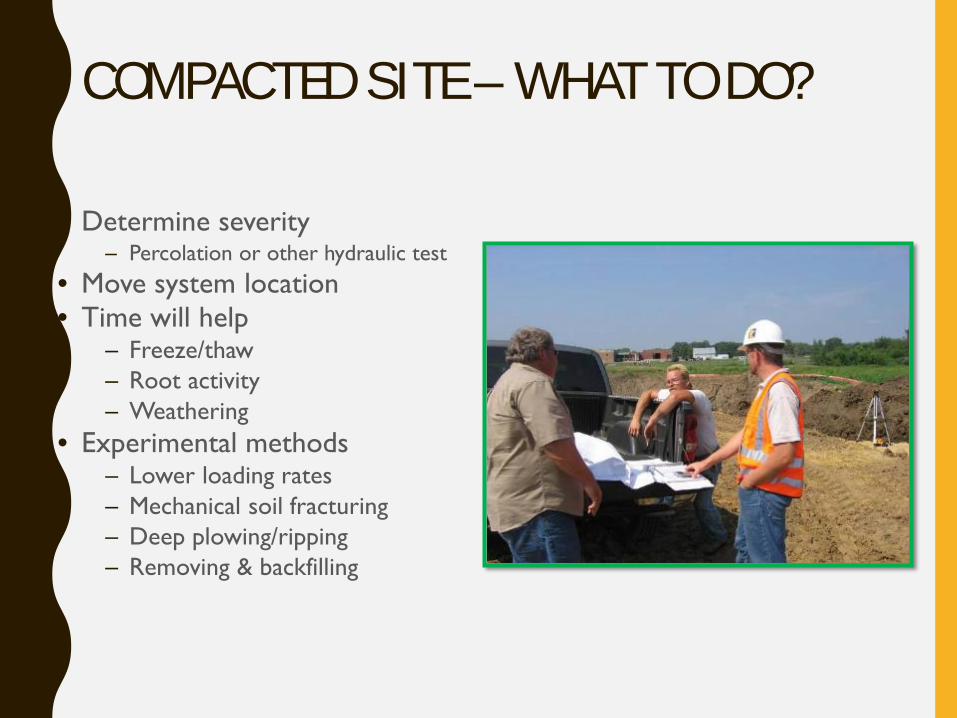
COMPACTED SITE – WHAT TO DO?
• Determine severity – Percolation or other hydraulic test
• Move system location• Time will help
– Freeze/thaw– Root activity– Weathering
• Experimental methods– Lower loading rates– Mechanical soil fracturing– Deep plowing/ripping– Removing & backfilling
OTHER POTENTIAL SOLUTIONS• Rest the system
– Zone off a section of the soil treatment area
– Pump the tank and system (i.e. operate as a holding tank)
• Add compressed air and ‘beads’ to open up the soil
• Re-build and replace the distribution media in the system
– Typically a mound or sand fileter
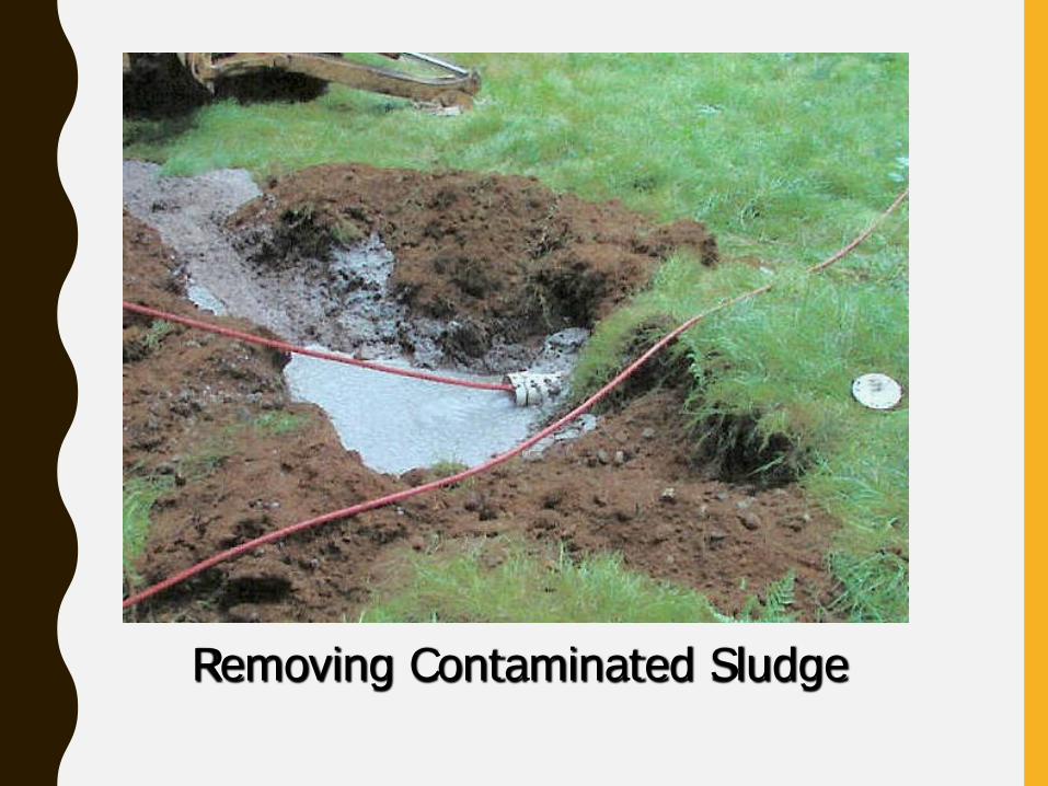
Removing Contaminated Sludge
MANAGEMENT PLAN
• For a MINIMUM of one year the system should be monitored to determine if the malfunction is resolved
• Measurements to make and record include:1. Whether the symptom of malfunction (surfacing or backing up)
stops
2. Depth of effluent ponding in the monitoring ports
3. Wastewater flow
IS A PERMIT REQUIRED?
• Yes, most of the time– Repair
– Adding a treatment component
• Either way this is a GOOD Idea– Tracking systems
– Tracking fixes
– Informing owners
OPERATING PERMIT
• How long practice going to occur and how often monitored
• Who is responsible for doing the monitoring
• Who is responsible for reporting to local unit of government
• Documentation of an agreement between the Maintainer/Service Provider and system owner
WHAT IF IT DOESN’T WORK?
• Owner of the system must notify local permitting authority
• Actions include:
– Discontinue the use of the remediation practice
– Potential interim use of another remediation practice
– Temporarily pump and haul
– Replace the system