Embed Size (px)
Citation preview
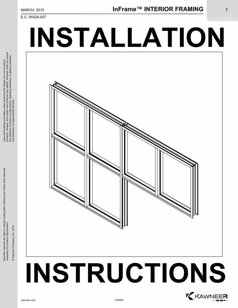
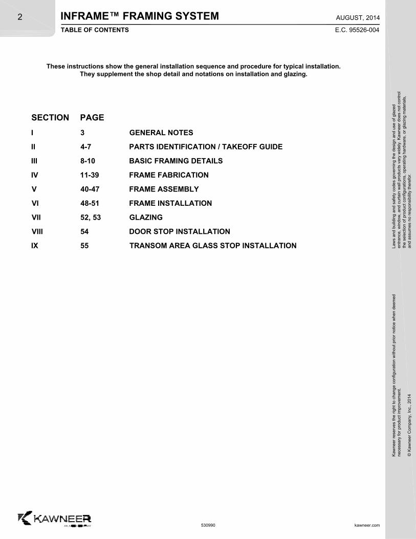
These instructions show the general installation sequence and procedure for typical installation.They supplement the shop detail and notations on installation and glazing.
TABLE OF CONTENTS E.C. 95526-004
kawneer.com
Law
s an
d bu
ildin
g a
nd s
afet
y co
des
gove
rnin
g th
e de
sign
and
use
of g
laze
de
ntra
nce,
win
dow
, a
nd c
urta
in w
all p
rod
ucts
var
y w
ide
ly.
Ka
wn
eer
does
not
con
trol
the
sel
ectio
n o
f pr
oduc
t co
nfig
urat
ions
, op
erat
ing
hard
wa
re,
or g
lazi
ng m
ater
ials
,a
nd a
ssum
es n
o re
spon
sibi
lity
ther
efor
.
2
SECTION PAGE
I 3 GENERAL NOTES
II 4-7 PARTS IDENTIFICATION / TAKEOFF GUIDE
III 8-10 BASIC FRAMING DETAILS
IV 11-39 FRAME FABRICATION
V 40-47 FRAME ASSEMBLY
VI 48-51 FRAME INSTALLATION
VII 52, 53 GLAZING
VIII 54 DOOR STOP INSTALLATION
IX 55 TRANSOM AREA GLASS STOP INSTALLATION
AUGUST, 2014
Kaw
neer
res
erve
s th
e rig
ht
to c
hang
e co
nfig
urat
ion
with
out
prio
r no
tice
whe
n de
emed
nec
essa
ry f
or p
rodu
ct im
pro
vem
ent.
© K
awne
er C
ompa
ny,
Inc.
, 201
4
INFRAME™ FRAMING SYSTEM
530990
INFRAME™ FRAMING SYSTEMK
awne
er r
eser
ves
the
righ
t to
cha
nge
conf
igur
atio
n w
ithou
t pr
ior
notic
e w
hen
deem
edn
eces
sary
for
pro
duct
imp
rove
men
t.
© K
awne
er C
ompa
ny,
Inc.
201
4
Law
s an
d bu
ildin
g a
nd s
afet
y co
des
gove
rnin
g th
e de
sign
and
use
of g
laze
de
ntra
nce,
win
dow
, a
nd c
urta
in w
all p
rod
ucts
var
y w
ide
ly.
Ka
wn
eer
does
not
con
trol
the
sel
ectio
n o
f pr
oduc
t co
nfig
urat
ions
, op
erat
ing
hard
wa
re,
or g
lazi
ng m
ater
ials
,a
nd a
ssum
es n
o re
spon
sibi
lity
ther
efor
.3
kawneer.com
E.C. 95526-004
AUGUST, 2014
SECTION I - GENERAL NOTES
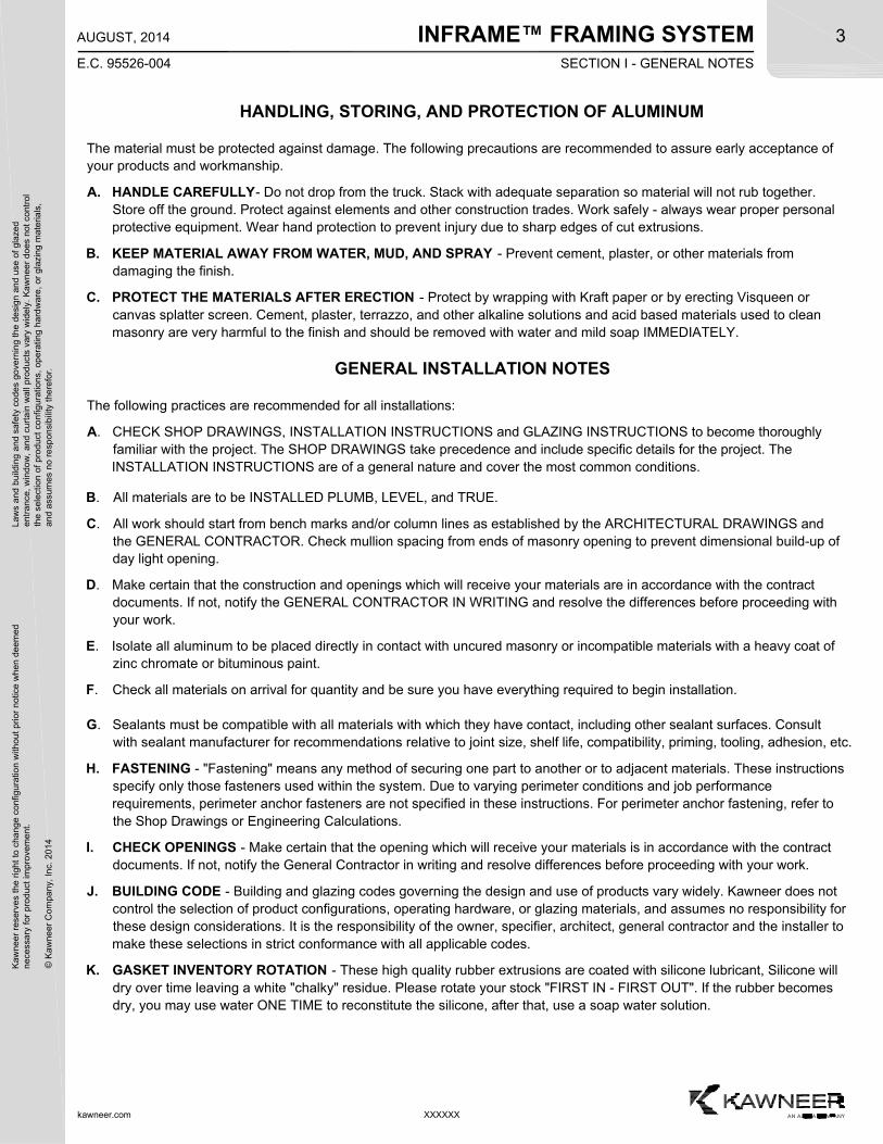
HANDLING, STORING, AND PROTECTION OF ALUMINUM
The material must be protected against damage. The following precautions are recommended to assure early acceptance ofyour products and workmanship.
A. HANDLE CAREFULLY- Do not drop from the truck. Stack with adequate separation so material will not rub together.Store off the ground. Protect against elements and other construction trades. Work safely - always wear proper personalprotective equipment. Wear hand protection to prevent injury due to sharp edges of cut extrusions.
B. KEEP MATERIAL AWAY FROM WATER, MUD, AND SPRAY - Prevent cement, plaster, or other materials fromdamaging the finish.
C. PROTECT THE MATERIALS AFTER ERECTION - Protect by wrapping with Kraft paper or by erecting Visqueen orcanvas splatter screen. Cement, plaster, terrazzo, and other alkaline solutions and acid based materials used to cleanmasonry are very harmful to the finish and should be removed with water and mild soap IMMEDIATELY.
GENERAL INSTALLATION NOTES
The following practices are recommended for all installations:
A. CHECK SHOP DRAWINGS, INSTALLATION INSTRUCTIONS and GLAZING INSTRUCTIONS to become thoroughlyfamiliar with the project. The SHOP DRAWINGS take precedence and include specific details for the project. TheINSTALLATION INSTRUCTIONS are of a general nature and cover the most common conditions.
B. All materials are to be INSTALLED PLUMB, LEVEL, and TRUE.
C. All work should start from bench marks and/or column lines as established by the ARCHITECTURAL DRAWINGS andthe GENERAL CONTRACTOR. Check mullion spacing from ends of masonry opening to prevent dimensional build-up ofday light opening.
D. Make certain that the construction and openings which will receive your materials are in accordance with the contractdocuments. If not, notify the GENERAL CONTRACTOR IN WRITING and resolve the differences before proceeding withyour work.
E. Isolate all aluminum to be placed directly in contact with uncured masonry or incompatible materials with a heavy coat ofzinc chromate or bituminous paint.
F. Check all materials on arrival for quantity and be sure you have everything required to begin installation.
G. Sealants must be compatible with all materials with which they have contact, including other sealant surfaces. Consultwith sealant manufacturer for recommendations relative to joint size, shelf life, compatibility, priming, tooling, adhesion, etc.
H. FASTENING - "Fastening" means any method of securing one part to another or to adjacent materials. These instructionsspecify only those fasteners used within the system. Due to varying perimeter conditions and job performancerequirements, perimeter anchor fasteners are not specified in these instructions. For perimeter anchor fastening, refer tothe Shop Drawings or Engineering Calculations.
I. CHECK OPENINGS - Make certain that the opening which will receive your materials is in accordance with the contractdocuments. If not, notify the General Contractor in writing and resolve differences before proceeding with your work.
J. BUILDING CODE - Building and glazing codes governing the design and use of products vary widely. Kawneer does notcontrol the selection of product configurations, operating hardware, or glazing materials, and assumes no responsibility forthese design considerations. It is the responsibility of the owner, specifier, architect, general contractor and the installer tomake these selections in strict conformance with all applicable codes.
K. GASKET INVENTORY ROTATION - These high quality rubber extrusions are coated with silicone lubricant, Silicone willdry over time leaving a white "chalky" residue. Please rotate your stock "FIRST IN - FIRST OUT". If the rubber becomesdry, you may use water ONE TIME to reconstitute the silicone, after that, use a soap water solution.
XXXXXX
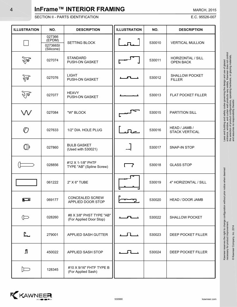
InFrame™ INTERIOR FRAMINGSECTION II - PARTS IDENTIFICATION
kawneer.com
4
E.C. 95526-007
MARCH, 2015
Kaw
neer
res
erve
s th
e rig
ht
to c
hang
e co
nfig
urat
ion
with
out
prio
r no
tice
whe
n de
emed
nec
essa
ry f
or p
rodu
ct im
pro
vem
ent.
© K
awne
er C
ompa
ny,
Inc.
201
4
Law
s an
d bu
ildin
g a
nd s
afet
y co
des
gove
rnin
g th
e de
sign
and
use
of g
laze
de
ntra
nce,
win
dow
, a
nd c
urta
in w
all p
rod
ucts
var
y w
ide
ly.
Ka
wn
eer
does
not
con
trol
the
sel
ectio
n o
f pr
oduc
t co
nfig
urat
ions
, op
erat
ing
hard
wa
re,
or g
lazi
ng m
ater
ials
,a
nd a
ssum
es n
o re
spon
sibi
lity
ther
efor
.
ILLUSTRATION NO. DESCRIPTION DESCRIPTIONILLUSTRATION NO.
530012
VERTICAL MULLION
2" X 6" TUBE
530011
530010
061222
"W" BLOCK027084
027077
027076
SNAP-IN STOP
530018
530019
530017
FLAT POCKET FILLER530013
OPEN BACKHORIZONTAL / SILL
FILLERSHALLOW POCKET
GLASS STOP
530023
530020 HEAD / DOOR JAMB
530022 SHALLOW POCKET
DEEP POCKET FILLER
027860
028856#12 X 1-1/8" PHTFTYPE "AB" (Spline Screw)
027074
530990
SETTING BLOCK
STANDARDPUSH-ON GASKET
LIGHT
HEAVY
PUSH-ON GASKET
PUSH-ON GASKET
PARTITION SILL530015
530016
DEEP POCKET FILLER530024
4" HORIZONTAL / SILL
HEAD / JAMB /STACK VERTICAL
069177APPLIED DOOR STOPCONCEALED SCREW
APPLIED SASH GUTTER279001
APPLIED SASH STOP450022
BULB GASKET(Used with 530021)
027633 1/2" DIA. HOLE PLUG
028260(For Applied Door Stop)#8 X 3/8" PHST TYPE "AB"
128345(For Applied Sash)#10 X 9/16" FHTF TYPE B
027366(EPDM)
027366SI(Silicone)
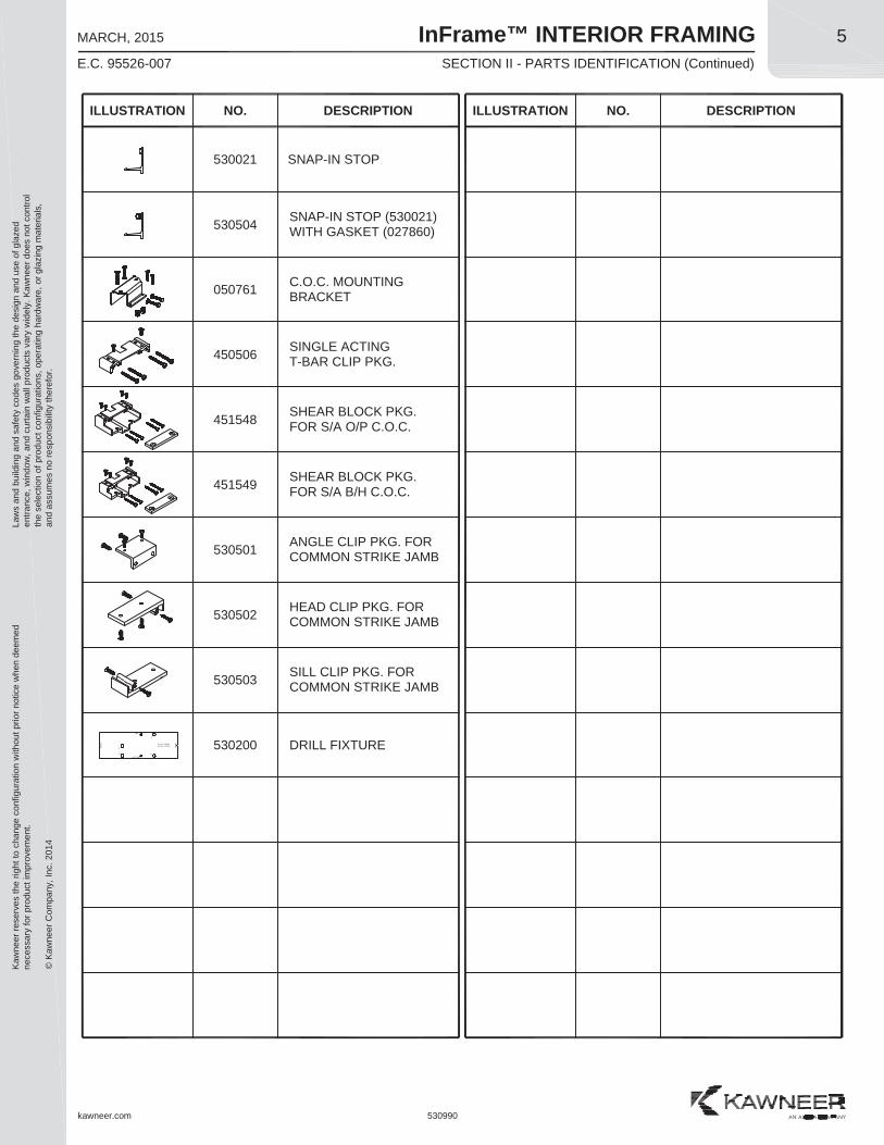
InFrame™ INTERIOR FRAMINGSECTION II - PARTS IDENTIFICATION (Continued)
Kaw
neer
rese
rves
the
right
to c
hang
e co
nfig
urat
ion
with
out p
rior n
otic
e w
hen
deem
edne
cess
ary
for p
rodu
ct im
prov
emen
t.
© K
awne
er C
ompa
ny, I
nc. 2
014
Law
s an
d bu
ildin
g an
d sa
fety
cod
es g
over
ning
the
desi
gn a
nd u
se o
f gla
zed
entra
nce,
win
dow
, and
cur
tain
wal
l pro
duct
s va
ry w
idel
y. K
awne
er d
oes
not c
ontro
lth
e se
lect
ion
of p
rodu
ct c
onfig
urat
ions
, ope
ratin
g ha
rdw
are,
or g
lazi
ng m
ater
ials
,an
d as
sum
es n
o re
spon
sibi
lity
ther
efor
.5
kawneer.com
E.C. 95526-007
MARCH, 2015
ILLUSTRATION NO. DESCRIPTION DESCRIPTIONILLUSTRATION NO.
C.O.C. MOUNTINGBRACKET050761
451548
451549
530990
450506
DRILL FIXTURE530200
HEAD CLIP PKG. FORCOMMON STRIKE JAMB530502
530501 ANGLE CLIP PKG. FORCOMMON STRIKE JAMB
530503 SILL CLIP PKG. FORCOMMON STRIKE JAMB
C
FRO
NT
B
BOTTOM
BA
CK
TOP
D
Part No. 530200Use No. 1 DRILL
A
SHEAR BLOCK PKG.FOR S/A O/P C.O.C.
SINGLE ACTINGT-BAR CLIP PKG.
SHEAR BLOCK PKG.FOR S/A B/H C.O.C.
530504 SNAP-IN STOP (530021)WITH GASKET (027860)
530021 SNAP-IN STOP
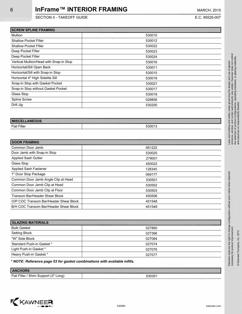
InFrame™ INTERIOR FRAMINGSECTION II - TAKEOFF GUIDE
kawneer.com
6
E.C. 95526-007
MARCH, 2015
Kaw
neer
res
erve
s th
e rig
ht
to c
hang
e co
nfig
urat
ion
with
out
prio
r no
tice
whe
n de
emed
nec
essa
ry f
or p
rodu
ct im
pro
vem
ent.
© K
awne
er C
ompa
ny,
Inc.
201
4
Law
s an
d bu
ildin
g a
nd s
afet
y co
des
gove
rnin
g th
e de
sign
and
use
of g
laze
de
ntra
nce,
win
dow
, a
nd c
urta
in w
all p
rod
ucts
var
y w
ide
ly.
Ka
wn
eer
does
not
con
trol
the
sel
ectio
n o
f pr
oduc
t co
nfig
urat
ions
, op
erat
ing
hard
wa
re,
or g
lazi
ng m
ater
ials
,a
nd a
ssum
es n
o re
spon
sibi
lity
ther
efor
.
530990
Mullion
SCREW SPLINE FRAMING
DOOR FRAMING
530010
Common Door Jamb 061222
Shallow Pocket Filler 530012
Shallow Pocket Filler 530022
Deep Pocket Filler 530023
530024
530016
530011
530015
530019
530021
530017
530013
530018
Deep Pocket Filler
Vertical Mullion/Head with Snap-in Stop
Horizontal/Sill Open Back
Horizontal/Sill with Snap-in Stop
Horizontal 4" High Sidelite Sill
Snap-in Stop with Gasket Pocket
Snap-in Stop without Gasket Pocket
Flat Filler
Glass Stop
Spline Screw
Drill Jig
028856
530200
Door Jamb with Snap-in Stop 530020
Applied Sash Gutter 279001
Glass Stop 450022
Applied Sash Fastener 128345
1" Door Stop Package 069177
Common Door Jamb Angle Clip at Head 530501
Common Door Jamb Clip at Head 530502
Common Door Jamb Clip at Floor 530503
Transom Bar/Header Shear Block 450506
O/P COC Transom Bar/Header Shear Block 451548
B/H COC Transom Bar/Header Shear Block 451549
GLAZING MATERIALS
Bulb Gasket 027860
Setting Block 027366
"W" Side Block 027084
Standard Push-in Gasket * 027074
Light Push-in Gasket * 027076
Heavy Push-in Gasket * 027077
* NOTE: Reference page 53 for gasket combinations with available infills.
ANCHORS
Flat Filler / Shim Support (3" Long) 530301
MISCELLANEOUS
InFrame™ INTERIOR FRAMINGK
awne
er r
eser
ves
the
righ
t to
cha
nge
conf
igur
atio
n w
ithou
t pr
ior
notic
e w
hen
deem
edn
eces
sary
for
pro
duct
imp
rove
men
t.
© K
awne
er C
ompa
ny,
Inc.
201
4
Law
s an
d bu
ildin
g a
nd s
afet
y co
des
gove
rnin
g th
e de
sign
and
use
of g
laze
de
ntra
nce,
win
dow
, a
nd c
urta
in w
all p
rod
ucts
var
y w
ide
ly.
Ka
wn
eer
does
not
con
trol
the
sel
ectio
n o
f pr
oduc
t co
nfig
urat
ions
, op
erat
ing
hard
wa
re,
or g
lazi
ng m
ater
ials
,a
nd a
ssum
es n
o re
spon
sibi
lity
ther
efor
.7
kawneer.com
E.C. 95526-004
AUGUST, 2014
530990
SECTION II - TAKEOFF GUIDE
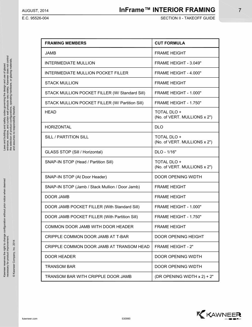
FRAMING MEMBERS CUT FORMULA
JAMB FRAME HEIGHT
INTERMEDIATE MULLION FRAME HEIGHT - 3.049"
INTERMEDIATE MULLION POCKET FILLER FRAME HEIGHT - 4.000"
STACK MULLION FRAME HEIGHT
STACK MULLION POCKET FILLER (W/ Standard Sill) FRAME HEIGHT - 1.000"
STACK MULLION POCKET FILLER (W/ Partition Sill) FRAME HEIGHT - 1.750"
HEAD TOTAL DLO +(No. of VERT. MULLIONS x 2")
HORIZONTAL DLO
SILL / PARTITION SILL TOTAL DLO +(No. of VERT. MULLIONS x 2")
GLASS STOP (Sill / Horizontal) DLO - 1/16"
SNAP-IN STOP (Head / Partition Sill) TOTAL DLO +(No. of VERT. MULLIONS x 2")
SNAP-IN STOP (At Door Header) DOOR OPENING WIDTH
SNAP-IN STOP (Jamb / Stack Mullion / Door Jamb) FRAME HEIGHT
DOOR JAMB FRAME HEIGHT
DOOR JAMB POCKET FILLER (With Standard Sill) FRAME HEIGHT - 1.000"
DOOR JAMB POCKET FILLER (With Partition Sill) FRAME HEIGHT - 1.750"
COMMON DOOR JAMB WITH DOOR HEADER FRAME HEIGHT
CRIPPLE COMMON DOOR JAMB AT T-BAR DOOR OPENING HEIGHT
CRIPPLE COMMON DOOR JAMB AT TRANSOM HEAD FRAME HEIGHT - 2"
DOOR HEADER DOOR OPENING WIDTH
TRANSOM BAR DOOR OPENING WIDTH
TRANSOM BAR WITH CRIPPLE DOOR JAMB (DR OPENING WIDTH x 2) + 2"
InFrame™ INTERIOR FRAMING
kawneer.com
8
E.C. 95526-004
AUGUST, 2014
Kaw
neer
res
erve
s th
e rig
ht
to c
hang
e co
nfig
urat
ion
with
out
prio
r no
tice
whe
n de
emed
nec
essa
ry f
or p
rodu
ct im
pro
vem
ent.
© K
awne
er C
ompa
ny,
Inc.
201
4
Law
s an
d bu
ildin
g a
nd s
afet
y co
des
gove
rnin
g th
e de
sign
and
use
of g
laze
de
ntra
nce,
win
dow
, a
nd c
urta
in w
all p
rod
ucts
var
y w
ide
ly.
Ka
wn
eer
does
not
con
trol
the
sel
ectio
n o
f pr
oduc
t co
nfig
urat
ions
, op
erat
ing
hard
wa
re,
or g
lazi
ng m
ater
ials
,a
nd a
ssum
es n
o re
spon
sibi
lity
ther
efor
.
530990
SECTION III - BASIC FRAMING DETAILS
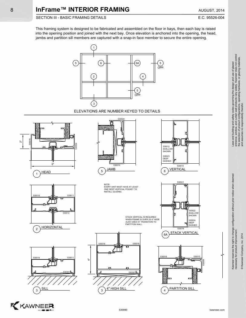
This framing system is designed to be fabricated and assembled on the floor in bays, then each bay is raisedinto the opening position and joined with the next bay. Once elevation is anchored into the opening, the head,jambs and partition sill members are captured with a snap-in face member to secure the entire opening.
5
OPP.
6
1
3
42
5
5
OPP.
530011530018
530012
530015530018
5305
04
5300
16
5305
04
530301
530011530018
530301
530019530018
1HEAD
2HORIZONTAL
3SILL
530010
530016
530021
530016
530504
5JAMB
6VERTICAL
4PARTITION SILL
ELEVATIONS ARE NUMBER KEYED TO DETAILS
34" HIGH SILL
6ASTACK VERTICAL
6"
2"
4"
6A
530012SHALLOWSHOWN
530023DEEPDASHED
530022SHALLOWSHOWN
530024DEEPDASHED
STACK VERTICAL IS REQUIREDWHEN FRAME IS OVER 20'-0" WIDE.ALSO USED AT TRANSITION TOPARTITION WALL.
NOTE:EVERY UNIT MUST HAVE AT LEASTONE DEEP VERTICAL POCKET TOINSTALL GLAZING.
InFrame™ INTERIOR FRAMINGK
awne
er r
eser
ves
the
righ
t to
cha
nge
conf
igur
atio
n w
ithou
t pr
ior
notic
e w
hen
deem
edn
eces
sary
for
pro
duct
imp
rove
men
t.
© K
awne
er C
ompa
ny,
Inc.
201
4
Law
s an
d bu
ildin
g a
nd s
afet
y co
des
gove
rnin
g th
e de
sign
and
use
of g
laze
de
ntra
nce,
win
dow
, a
nd c
urta
in w
all p
rod
ucts
var
y w
ide
ly.
Ka
wn
eer
does
not
con
trol
the
sel
ectio
n o
f pr
oduc
t co
nfig
urat
ions
, op
erat
ing
hard
wa
re,
or g
lazi
ng m
ater
ials
,a
nd a
ssum
es n
o re
spon
sibi
lity
ther
efor
.9
kawneer.com
E.C. 95526-004
AUGUST, 2014
530990
SECTION III - BASIC FRAMING DETAILS
5
1
SS SS
SS SS
419 13
OPP.
1
19 13
OPP.
10
13
17
18
SS
SB
SS
SBSS SSSB
18
OPP.
7
SB
8
ELEVATIONS ARE NUMBER KEYED TO DETAILS
5305
045300
20
069177 STOPASSEMBLY
279001450022
069177 STOP ASSEMBLY450506 S/A T-BAR CLIP PKG.
279001450022 279001450022
049064 STOP ASSEMBLY450506 S/A T-BAR CLIP PKG
041045 STOP451141 S/A T-BAR CLIP PKG451548 COC O/P SHEAR BLOCK451549 COC B/H SHEAR BLOCK
7HEADAT DOOR
10TRANSOM BAR W/ COC OR SURFACE CLOSER
10TRANSOM BAR W/ COCFOR LCN CLOSER
10TRANSOM BAR W/ COCFOR STD. KAWNEER CLOSER
5305
045300
20
8HEADAT COMMON DOOR JAMB
5300
16
5305
04
9TRANSOM HEADAT COMMON DOOR JAMB
0612
22
0612
22
0612
22
530501 ANGLE CLIP PKG
530502 COMMON MULLIONCLIP PKG.
12
12SILL CLIPAT COMMON DOOR JAMB
530503 COMMON MULLIONCLIP PKG.
11
279001450022
530502 COMMON MULLIONCLIP PKG.
11HEAD CLIPAT COMMON DOOR JAMB
0612
22
12
SB
13
SS = SCREW SPLINESB = SHEAR BLOCK
InFrame™ INTERIOR FRAMING
kawneer.com
10
E.C. 95526-004
AUGUST, 2014
Kaw
neer
res
erve
s th
e rig
ht
to c
hang
e co
nfig
urat
ion
with
out
prio
r no
tice
whe
n de
emed
nec
essa
ry f
or p
rodu
ct im
pro
vem
ent.
© K
awne
er C
ompa
ny,
Inc.
201
4
Law
s an
d bu
ildin
g a
nd s
afet
y co
des
gove
rnin
g th
e de
sign
and
use
of g
laze
de
ntra
nce,
win
dow
, a
nd c
urta
in w
all p
rod
ucts
var
y w
ide
ly.
Ka
wn
eer
does
not
con
trol
the
sel
ectio
n o
f pr
oduc
t co
nfig
urat
ions
, op
erat
ing
hard
wa
re,
or g
lazi
ng m
ater
ials
,a
nd a
ssum
es n
o re
spon
sibi
lity
ther
efor
.
530990
SECTION III - BASIC FRAMING DETAILS
061222
069177 STOPASSEMBLY
069177 STOPASSEMBLY
530020
530021
530504
530020
069177 STOPASSEMBLY
530020
530021
069177 STOPASSEMBLY
530504
530020
450022
279001
450022
279001
5
SS SS
SS SB
419 13
OPP.
1
15 5
OPP.
13
17
18
SS
SS
SB
SS
SS SSSB SB
SB SB
10
ELEVATIONS ARE NUMBER KEYED TO DETAILS
3
2
13DOOR JAMB
14TRANSOM JAMB
15DOOR JAMB
16TRANSOM JAMB
17DOOR JAMB
18TRANSOM JAMB
19COMMON DOOR JAMB
1
450022
279001
061222
450022
279001
20COMMON TRANSOM JAMB
20 14
OPP.
14 16
12
9
10SSSB
SS
SS
SB
SS SS
SB
SS SS
13
530020
530021
069177 STOPASSEMBLY
530020
530021
450022
279001
530022SHALLOWSHOWN
530024DEEPDASHED
530022SHALLOW
SHOWN
530024DEEP
DASHED
530022SHALLOWSHOWN
530024DEEPDASHED
530022SHALLOW
SHOWN
530024DEEP
DASHED
SB
InFrame™ INTERIOR FRAMINGK
awne
er r
eser
ves
the
righ
t to
cha
nge
conf
igur
atio
n w
ithou
t pr
ior
notic
e w
hen
deem
edn
eces
sary
for
pro
duct
imp
rove
men
t.
© K
awne
er C
ompa
ny,
Inc.
201
4
Law
s an
d bu
ildin
g a
nd s
afet
y co
des
gove
rnin
g th
e de
sign
and
use
of g
laze
de
ntra
nce,
win
dow
, a
nd c
urta
in w
all p
rod
ucts
var
y w
ide
ly.
Ka
wn
eer
does
not
con
trol
the
sel
ectio
n o
f pr
oduc
t co
nfig
urat
ions
, op
erat
ing
hard
wa
re,
or g
lazi
ng m
ater
ials
,a
nd a
ssum
es n
o re
spon
sibi
lity
ther
efor
.11
kawneer.com
E.C. 95526-004
AUGUST, 2014
530990
SECTION IV - FRAME FABRICATION
C
FR
ON
T
B
BOTTOM
BA
CK
TOP
D
Part No. 530200Use No. 1 DRILL
A
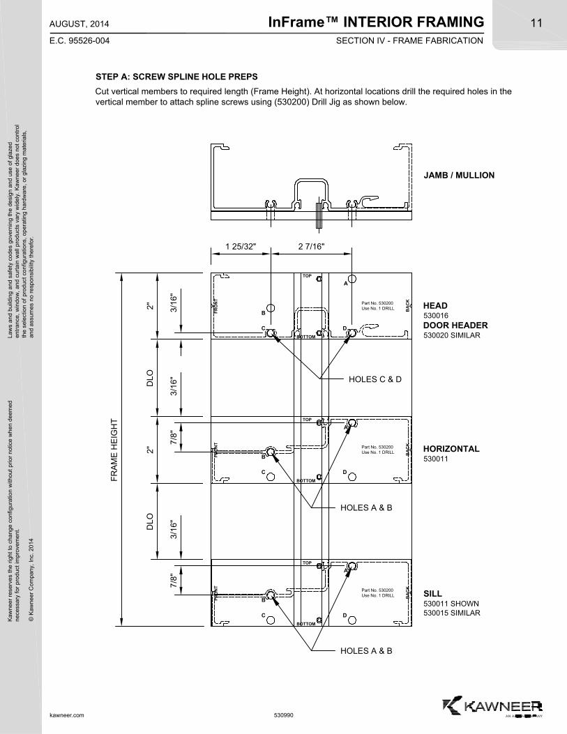
STEP A: SCREW SPLINE HOLE PREPS
FR
AM
E H
EIG
HT
2"2"
DLO
DLO
3/1
6"
HOLES C & D
HOLES A & B
HOLES A & B
Cut vertical members to required length (Frame Height). At horizontal locations drill the required holes in thevertical member to attach spline screws using (530200) Drill Jig as shown below.
3/1
6"7
/8"
3/1
6"7
/8"
C
FR
ON
T
B
BOTTOM
BA
CK
TOP
D
Part No. 530200Use No. 1 DRILL
A
C
FR
ON
T
B
BOTTOM
BA
CK
TOP
D
Part No. 530200Use No. 1 DRILL
A
JAMB / MULLION
HEAD530016DOOR HEADER530020 SIMILAR
HORIZONTAL530011
SILL530011 SHOWN530015 SIMILAR
1 25/32" 2 7/16"
InFrame™ INTERIOR FRAMING
kawneer.com
12
E.C. 95526-004
AUGUST, 2014
Kaw
neer
res
erve
s th
e rig
ht
to c
hang
e co
nfig
urat
ion
with
out
prio
r no
tice
whe
n de
emed
nec
essa
ry f
or p
rodu
ct im
pro
vem
ent.
© K
awne
er C
ompa
ny,
Inc.
201
4
Law
s an
d bu
ildin
g a
nd s
afet
y co
des
gove
rnin
g th
e de
sign
and
use
of g
laze
de
ntra
nce,
win
dow
, a
nd c
urta
in w
all p
rod
ucts
var
y w
ide
ly.
Ka
wn
eer
does
not
con
trol
the
sel
ectio
n o
f pr
oduc
t co
nfig
urat
ions
, op
erat
ing
hard
wa
re,
or g
lazi
ng m
ater
ials
,a
nd a
ssum
es n
o re
spon
sibi
lity
ther
efor
.
530990
SECTION IV - FRAME FABRICATION
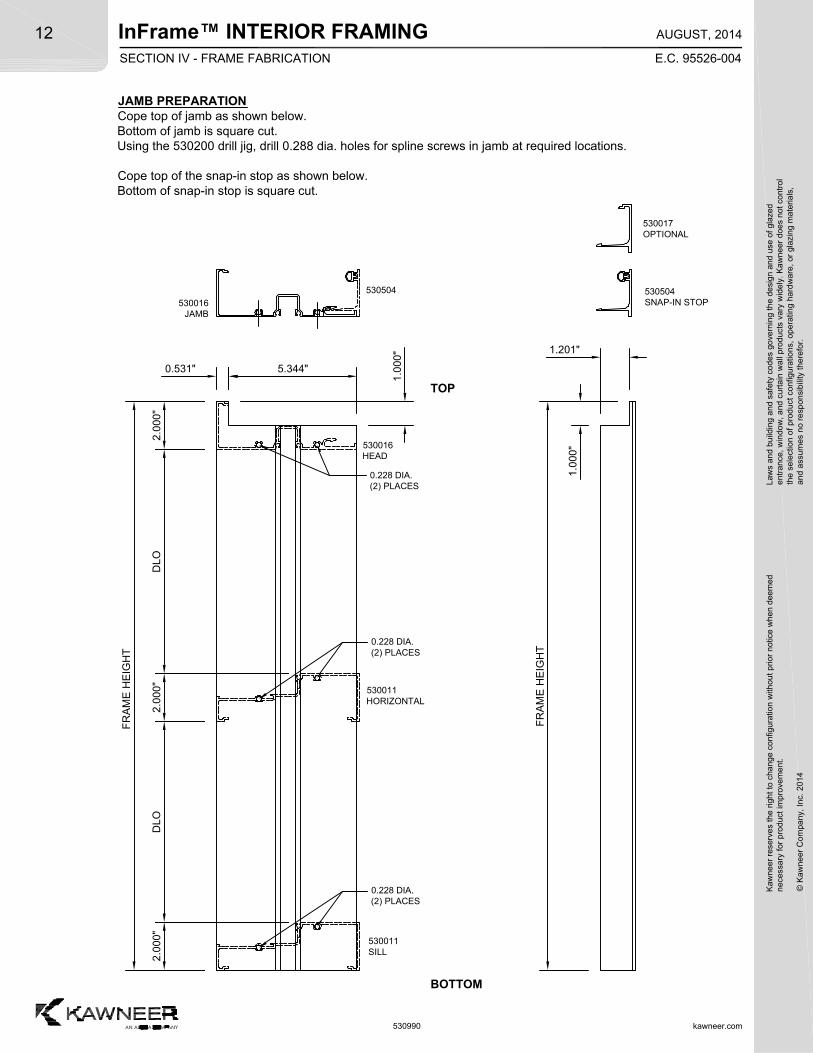
JAMB PREPARATIONCope top of jamb as shown below.Bottom of jamb is square cut.Using the 530200 drill jig, drill 0.288 dia. holes for spline screws in jamb at required locations.
Cope top of the snap-in stop as shown below.Bottom of snap-in stop is square cut.
TOP
BOTTOM
1.0
00"
FR
AM
E H
EIG
HT
0.228 DIA.(2) PLACES
FR
AM
E H
EIG
HT
1.201"
0.228 DIA.(2) PLACES
1.0
00"
5.344"
0.228 DIA.(2) PLACES
2.0
00"
DLO
2.0
00"
DLO
2.0
00"
0.531"
530016JAMB
530504SNAP-IN STOP
530011HORIZONTAL
530011SILL
530016HEAD
530017OPTIONAL
530504
InFrame™ INTERIOR FRAMINGK
awne
er r
eser
ves
the
righ
t to
cha
nge
conf
igur
atio
n w
ithou
t pr
ior
notic
e w
hen
deem
edn
eces
sary
for
pro
duct
imp
rove
men
t.
© K
awne
er C
ompa
ny,
Inc.
201
4
Law
s an
d bu
ildin
g a
nd s
afet
y co
des
gove
rnin
g th
e de
sign
and
use
of g
laze
de
ntra
nce,
win
dow
, a
nd c
urta
in w
all p
rod
ucts
var
y w
ide
ly.
Ka
wn
eer
does
not
con
trol
the
sel
ectio
n o
f pr
oduc
t co
nfig
urat
ions
, op
erat
ing
hard
wa
re,
or g
lazi
ng m
ater
ials
,a
nd a
ssum
es n
o re
spon
sibi
lity
ther
efor
.13
kawneer.com
E.C. 95526-004
AUGUST, 2014
530990
SECTION IV - FRAME FABRICATION
TOP
BOTTOM
1.0
00"
FR
AM
E H
EIG
HT
0.228 DIA.(2) PLACES
FR
AM
E H
EIG
HT
1.201"
0.228 DIA.(2) PLACES
1.0
00"
5.344"
0.228 DIA.(2) PLACES
2.0
00"
DLO
2.0
00"
DLO
2.0
00"
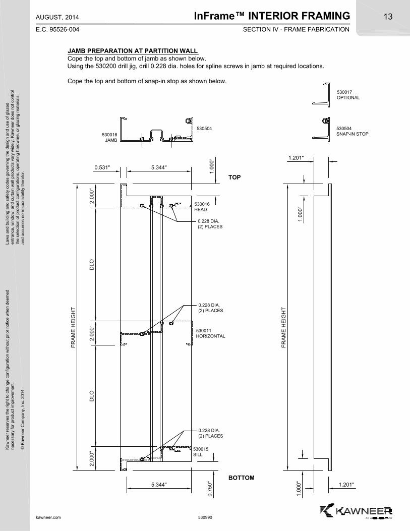
JAMB PREPARATION AT PARTITION WALLCope the top and bottom of jamb as shown below.Using the 530200 drill jig, drill 0.228 dia. holes for spline screws in jamb at required locations.
Cope the top and bottom of snap-in stop as shown below.
5.344"
0.7
50"
1.0
00"
1.201"
0.531"
530016JAMB
530504SNAP-IN STOP
530016HEAD
530011HORIZONTAL
530015SILL
530504
530017OPTIONAL
InFrame™ INTERIOR FRAMING
kawneer.com
14
E.C. 95526-004
AUGUST, 2014
Kaw
neer
res
erve
s th
e rig
ht
to c
hang
e co
nfig
urat
ion
with
out
prio
r no
tice
whe
n de
emed
nec
essa
ry f
or p
rodu
ct im
pro
vem
ent.
© K
awne
er C
ompa
ny,
Inc.
201
4
Law
s an
d bu
ildin
g a
nd s
afet
y co
des
gove
rnin
g th
e de
sign
and
use
of g
laze
de
ntra
nce,
win
dow
, a
nd c
urta
in w
all p
rod
ucts
var
y w
ide
ly.
Ka
wn
eer
does
not
con
trol
the
sel
ectio
n o
f pr
oduc
t co
nfig
urat
ions
, op
erat
ing
hard
wa
re,
or g
lazi
ng m
ater
ials
,a
nd a
ssum
es n
o re
spon
sibi
lity
ther
efor
.
530990
SECTION IV - FRAME FABRICATION
TOP
BOTTOM
FR
AM
E H
EIG
HT
- 3
.04
9"
0.228 DIA.(2) PLACES
DLO
2.0
00"
DLO
530010INTERMEDIATE VERTICAL
1.500"
3.312"
0.8
26"
FR
AM
E H
EIG
HT
- 4
.00
0"
DLO
2.0
00"
DLO
530012SHALLOW POCKET FILLER
530023DEEP POCKET FILLER
0.1
25"
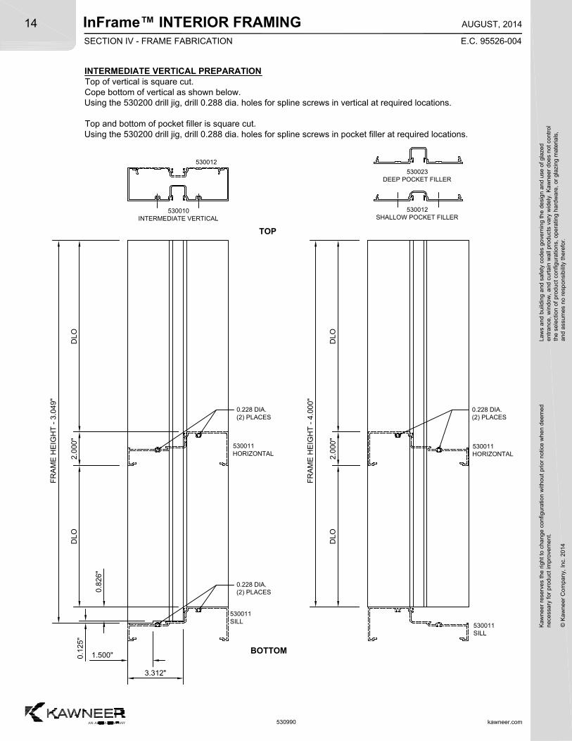
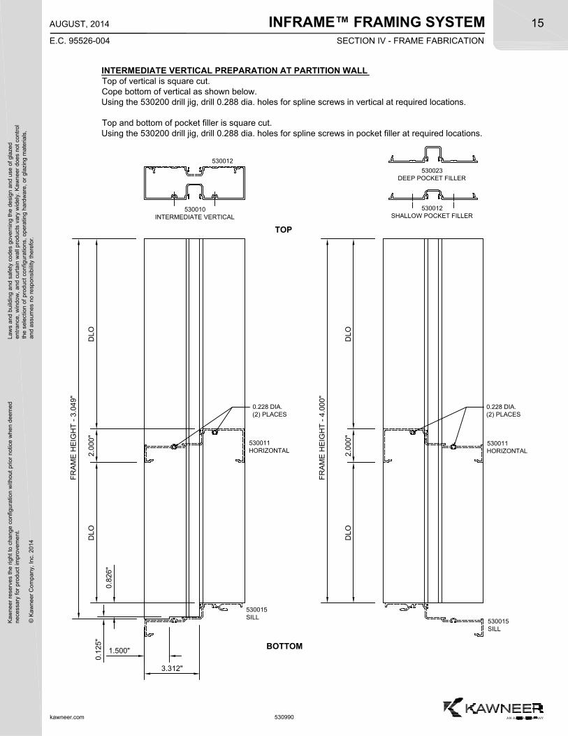
INTERMEDIATE VERTICAL PREPARATIONTop of vertical is square cut.Cope bottom of vertical as shown below.Using the 530200 drill jig, drill 0.288 dia. holes for spline screws in vertical at required locations.
Top and bottom of pocket filler is square cut.Using the 530200 drill jig, drill 0.288 dia. holes for spline screws in pocket filler at required locations.
530011SILL
530011HORIZONTAL
530011HORIZONTAL
0.228 DIA.(2) PLACES
530012
530011SILL
0.228 DIA.(2) PLACES
INFRAME™ FRAMING SYSTEMK
awne
er r
eser
ves
the
righ
t to
cha
nge
conf
igur
atio
n w
ithou
t pr
ior
notic
e w
hen
deem
edn
eces
sary
for
pro
duct
imp
rove
men
t.
© K
awne
er C
ompa
ny,
Inc.
201
4
Law
s an
d bu
ildin
g a
nd s
afet
y co
des
gove
rnin
g th
e de
sign
and
use
of g
laze
de
ntra
nce,
win
dow
, a
nd c
urta
in w
all p
rod
ucts
var
y w
ide
ly.
Ka
wn
eer
does
not
con
trol
the
sel
ectio
n o
f pr
oduc
t co
nfig
urat
ions
, op
erat
ing
hard
wa
re,
or g
lazi
ng m
ater
ials
,a
nd a
ssum
es n
o re
spon
sibi
lity
ther
efor
.15
kawneer.com
E.C. 95526-004
AUGUST, 2014
530990
SECTION IV - FRAME FABRICATION
TOP
BOTTOM
FR
AM
E H
EIG
HT
- 3
.04
9"
0.228 DIA.(2) PLACES
DLO
2.0
00"
DLO
530010INTERMEDIATE VERTICAL
1.500"
3.312"
0.8
26"
FR
AM
E H
EIG
HT
- 4
.00
0"
DLO
2.0
00"
DLO
530012SHALLOW POCKET FILLER
530023DEEP POCKET FILLER
0.1
25"
INTERMEDIATE VERTICAL PREPARATION AT PARTITION WALLTop of vertical is square cut.Cope bottom of vertical as shown below.Using the 530200 drill jig, drill 0.288 dia. holes for spline screws in vertical at required locations.
Top and bottom of pocket filler is square cut.Using the 530200 drill jig, drill 0.288 dia. holes for spline screws in pocket filler at required locations.
530015SILL
530011HORIZONTAL
530011HORIZONTAL
0.228 DIA.(2) PLACES
530012
530015SILL
INFRAME™ FRAMING SYSTEM
kawneer.com
16
E.C. 95526-004
AUGUST, 2014
Kaw
neer
res
erve
s th
e rig
ht
to c
hang
e co
nfig
urat
ion
with
out
prio
r no
tice
whe
n de
emed
nec
essa
ry f
or p
rodu
ct im
pro
vem
ent.
© K
awne
er C
ompa
ny,
Inc.
201
4
Law
s an
d bu
ildin
g a
nd s
afet
y co
des
gove
rnin
g th
e de
sign
and
use
of g
laze
de
ntra
nce,
win
dow
, a
nd c
urta
in w
all p
rod
ucts
var
y w
ide
ly.
Ka
wn
eer
does
not
con
trol
the
sel
ectio
n o
f pr
oduc
t co
nfig
urat
ions
, op
erat
ing
hard
wa
re,
or g
lazi
ng m
ater
ials
,a
nd a
ssum
es n
o re
spon
sibi
lity
ther
efor
.
530990
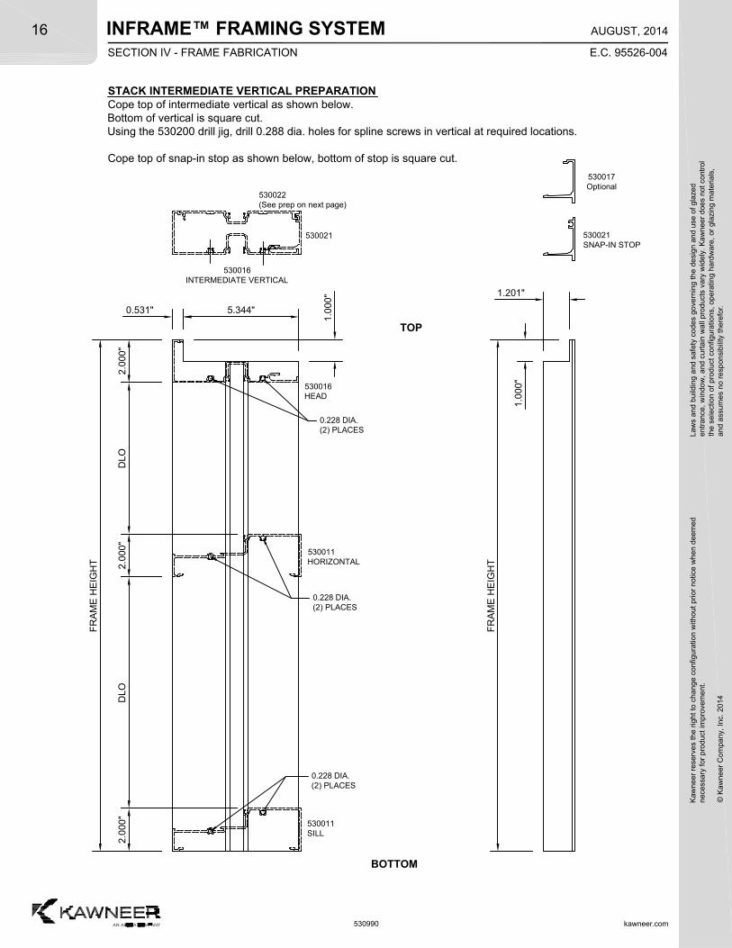
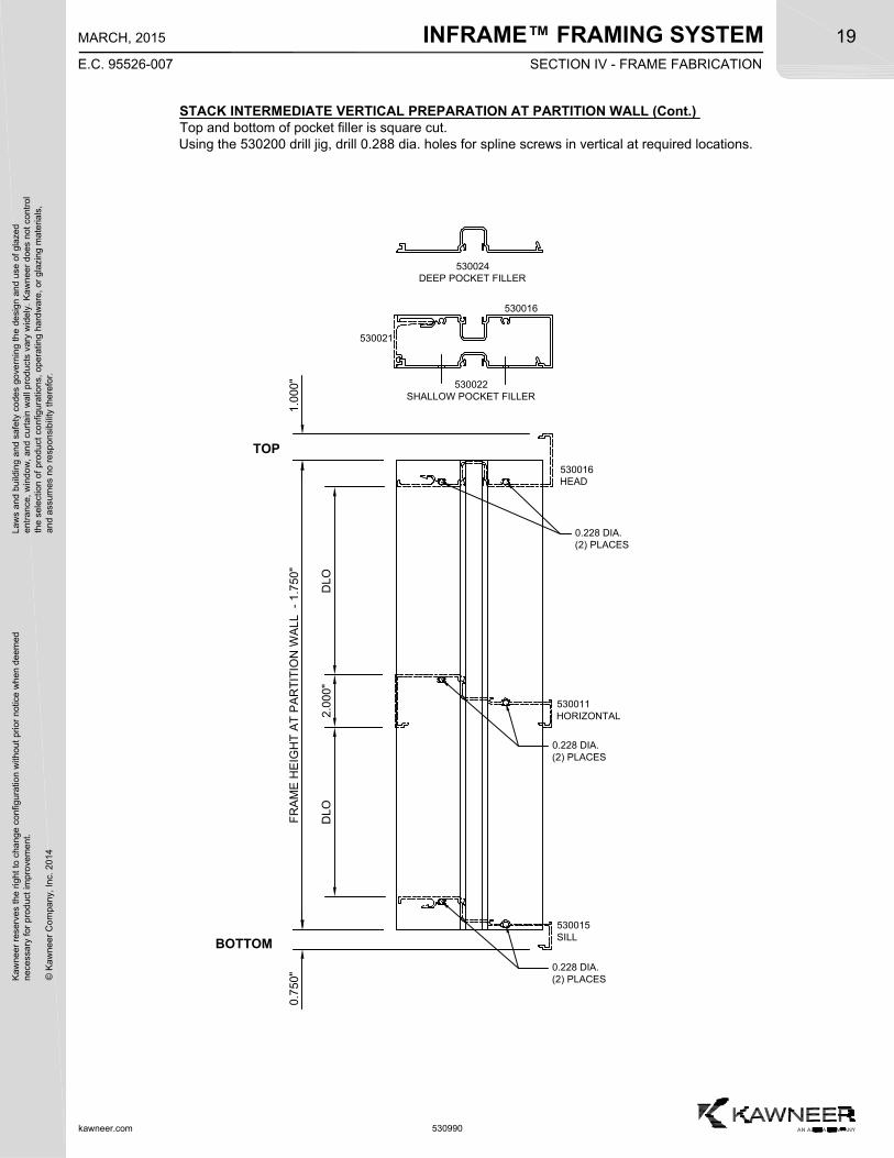
STACK INTERMEDIATE VERTICAL PREPARATIONCope top of intermediate vertical as shown below.Bottom of vertical is square cut.Using the 530200 drill jig, drill 0.288 dia. holes for spline screws in vertical at required locations.
Cope top of snap-in stop as shown below, bottom of stop is square cut.
TOP
BOTTOM
FR
AM
E H
EIG
HT
DLO
2.0
00"
DLO
530016INTERMEDIATE VERTICAL
1.0
00"
2.0
00"
0.531"
0.228 DIA.(2) PLACES
0.228 DIA.(2) PLACES
0.228 DIA.(2) PLACES
2.0
00"
530022(See prep on next page)
530021 530021SNAP-IN STOP
530016HEAD
530011HORIZONTAL
530011SILL
5.344"
1.0
00"
FR
AM
E H
EIG
HT
1.201"
530017Optional
SECTION IV - FRAME FABRICATION
INFRAME™ FRAMING SYSTEMK
awne
er r
eser
ves
the
righ
t to
cha
nge
conf
igur
atio
n w
ithou
t pr
ior
notic
e w
hen
deem
edn
eces
sary
for
pro
duct
imp
rove
men
t.
© K
awne
er C
ompa
ny,
Inc.
201
4
Law
s an
d bu
ildin
g a
nd s
afet
y co
des
gove
rnin
g th
e de
sign
and
use
of g
laze
de
ntra
nce,
win
dow
, a
nd c
urta
in w
all p
rod
ucts
var
y w
ide
ly.
Ka
wn
eer
does
not
con
trol
the
sel
ectio
n o
f pr
oduc
t co
nfig
urat
ions
, op
erat
ing
hard
wa
re,
or g
lazi
ng m
ater
ials
,a
nd a
ssum
es n
o re
spon
sibi
lity
ther
efor
.17
kawneer.com
E.C. 95526-007
MARCH, 2015
530990
FR
AM
E H
EIG
HT
- 1
.00
0"
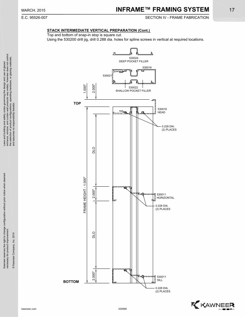
STACK INTERMEDIATE VERTICAL PREPARATION (Cont.)Top and bottom of snap-in stop is square cut.Using the 530200 drill jig, drill 0.288 dia. holes for spline screws in vertical at required locations.
TOP
BOTTOM
DLO
0.228 DIA.(2) PLACES
2.0
00"
DLO
530011HORIZONTAL
0.228 DIA.(2) PLACES
1.0
00"
0.228 DIA.(2) PLACES
530016HEAD
530022SHALLOW POCKET FILLER
530024DEEP POCKET FILLER
530016
530021
530011SILL2
.000
"2
.000
"
SECTION IV - FRAME FABRICATION
INFRAME™ FRAMING SYSTEM
kawneer.com
18
E.C. 95526-007
MARCH, 2015
Kaw
neer
res
erve
s th
e rig
ht
to c
hang
e co
nfig
urat
ion
with
out
prio
r no
tice
whe
n de
emed
nec
essa
ry f
or p
rodu
ct im
pro
vem
ent.
© K
awne
er C
ompa
ny,
Inc.
201
4
Law
s an
d bu
ildin
g a
nd s
afet
y co
des
gove
rnin
g th
e de
sign
and
use
of g
laze
de
ntra
nce,
win
dow
, a
nd c
urta
in w
all p
rod
ucts
var
y w
ide
ly.
Ka
wn
eer
does
not
con
trol
the
sel
ectio
n o
f pr
oduc
t co
nfig
urat
ions
, op
erat
ing
hard
wa
re,
or g
lazi
ng m
ater
ials
,a
nd a
ssum
es n
o re
spon
sibi
lity
ther
efor
.
530990
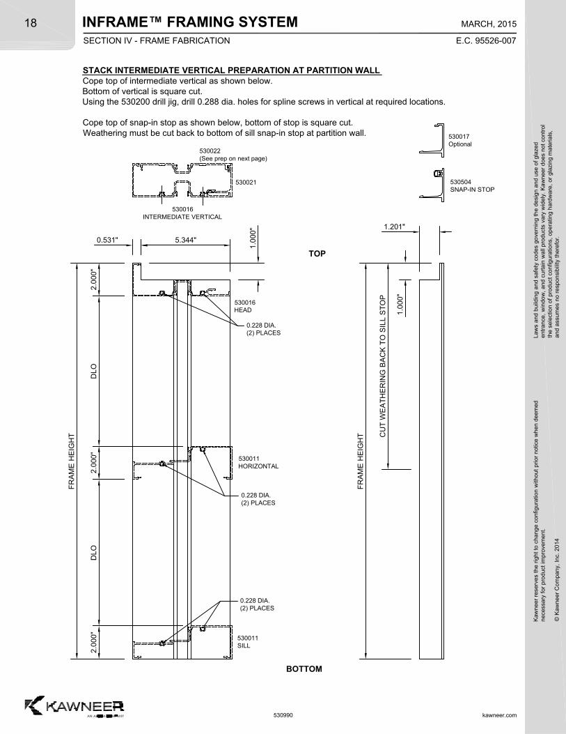
STACK INTERMEDIATE VERTICAL PREPARATION AT PARTITION WALLCope top of intermediate vertical as shown below.Bottom of vertical is square cut.Using the 530200 drill jig, drill 0.288 dia. holes for spline screws in vertical at required locations.
Cope top of snap-in stop as shown below, bottom of stop is square cut.Weathering must be cut back to bottom of sill snap-in stop at partition wall.
TOP
BOTTOM
FR
AM
E H
EIG
HT
DLO
2.0
00"
DLO
530016INTERMEDIATE VERTICAL
1.0
00"
2.0
00"
0.531"
0.228 DIA.(2) PLACES
0.228 DIA.(2) PLACES
0.228 DIA.(2) PLACES
2.0
00"
530022(See prep on next page)
530021 530504SNAP-IN STOP
530016HEAD
530011HORIZONTAL
530011SILL
5.344"
1.0
00"
FR
AM
E H
EIG
HT
1.201"
CU
T W
EA
TH
ER
ING
BA
CK
TO
SIL
L S
TO
P
530017Optional
SECTION IV - FRAME FABRICATION
INFRAME™ FRAMING SYSTEMK
awne
er r
eser
ves
the
righ
t to
cha
nge
conf
igur
atio
n w
ithou
t pr
ior
notic
e w
hen
deem
edn
eces
sary
for
pro
duct
imp
rove
men
t.
© K
awne
er C
ompa
ny,
Inc.
201
4
Law
s an
d bu
ildin
g a
nd s
afet
y co
des
gove
rnin
g th
e de
sign
and
use
of g
laze
de
ntra
nce,
win
dow
, a
nd c
urta
in w
all p
rod
ucts
var
y w
ide
ly.
Ka
wn
eer
does
not
con
trol
the
sel
ectio
n o
f pr
oduc
t co
nfig
urat
ions
, op
erat
ing
hard
wa
re,
or g
lazi
ng m
ater
ials
,a
nd a
ssum
es n
o re
spon
sibi
lity
ther
efor
.19
kawneer.com
E.C. 95526-007
MARCH, 2015
530990
STACK INTERMEDIATE VERTICAL PREPARATION AT PARTITION WALL (Cont.)Top and bottom of pocket filler is square cut.Using the 530200 drill jig, drill 0.288 dia. holes for spline screws in vertical at required locations.
530022SHALLOW POCKET FILLER
530024DEEP POCKET FILLER
FR
AM
E H
EIG
HT
AT
PA
RT
ITIO
N W
AL
L -
1.7
50"
TOP
BOTTOM
DLO
0.228 DIA.(2) PLACES
2.0
00"
DLO
530011HORIZONTAL
530015SILL
0.228 DIA.(2) PLACES
0.7
50"
1.0
00"
0.228 DIA.(2) PLACES
530016HEAD
530016
530021
SECTION IV - FRAME FABRICATION
INFRAME™ FRAMING SYSTEM
kawneer.com
20
E.C. 95526-004
AUGUST, 2014
Kaw
neer
res
erve
s th
e rig
ht
to c
hang
e co
nfig
urat
ion
with
out
prio
r no
tice
whe
n de
emed
nec
essa
ry f
or p
rodu
ct im
pro
vem
ent.
© K
awne
er C
ompa
ny,
Inc.
201
4
Law
s an
d bu
ildin
g a
nd s
afet
y co
des
gove
rnin
g th
e de
sign
and
use
of g
laze
de
ntra
nce,
win
dow
, a
nd c
urta
in w
all p
rod
ucts
var
y w
ide
ly.
Ka
wn
eer
does
not
con
trol
the
sel
ectio
n o
f pr
oduc
t co
nfig
urat
ions
, op
erat
ing
hard
wa
re,
or g
lazi
ng m
ater
ials
,a
nd a
ssum
es n
o re
spon
sibi
lity
ther
efor
.
530990
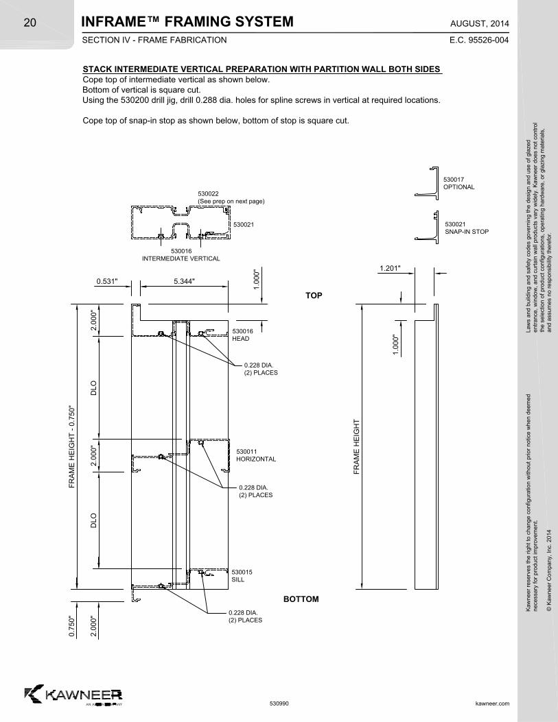
STACK INTERMEDIATE VERTICAL PREPARATION WITH PARTITION WALL BOTH SIDESCope top of intermediate vertical as shown below.Bottom of vertical is square cut.Using the 530200 drill jig, drill 0.288 dia. holes for spline screws in vertical at required locations.
Cope top of snap-in stop as shown below, bottom of stop is square cut.
TOP
BOTTOM
FR
AM
E H
EIG
HT
- 0
.75
0"
DLO
2.0
00"
DLO
530016INTERMEDIATE VERTICAL
1.0
00"
2.0
00"
0.531"
0.228 DIA.(2) PLACES
0.228 DIA.(2) PLACES
530022(See prep on next page)
530021 530021SNAP-IN STOP
530016HEAD
530011HORIZONTAL
5.344"
1.0
00"
FR
AM
E H
EIG
HT
1.201"
530017OPTIONAL
530015SILL
0.228 DIA.(2) PLACES
0.7
50"
2.0
00"
SECTION IV - FRAME FABRICATION
INFRAME™ FRAMING SYSTEMK
awne
er r
eser
ves
the
righ
t to
cha
nge
conf
igur
atio
n w
ithou
t pr
ior
notic
e w
hen
deem
edn
eces
sary
for
pro
duct
imp
rove
men
t.
© K
awne
er C
ompa
ny,
Inc.
201
4
Law
s an
d bu
ildin
g a
nd s
afet
y co
des
gove
rnin
g th
e de
sign
and
use
of g
laze
de
ntra
nce,
win
dow
, a
nd c
urta
in w
all p
rod
ucts
var
y w
ide
ly.
Ka
wn
eer
does
not
con
trol
the
sel
ectio
n o
f pr
oduc
t co
nfig
urat
ions
, op
erat
ing
hard
wa
re,
or g
lazi
ng m
ater
ials
,a
nd a
ssum
es n
o re
spon
sibi
lity
ther
efor
.21
kawneer.com
E.C. 95526-004
AUGUST, 2014
530990
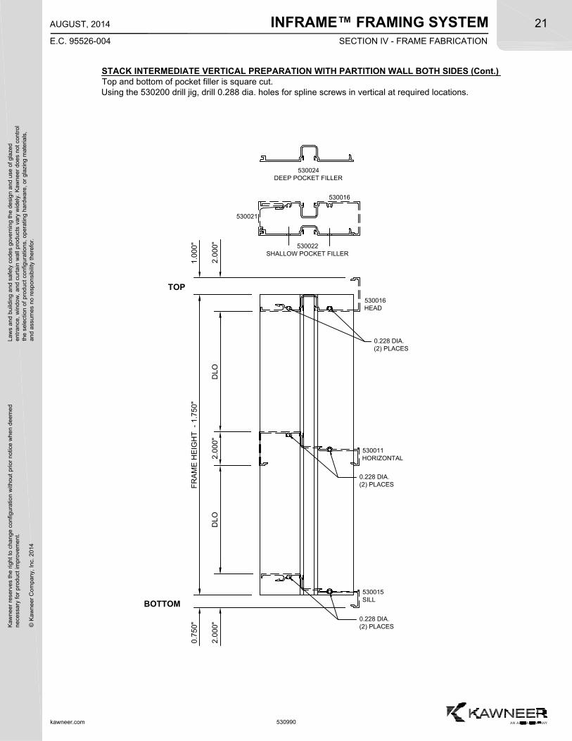
STACK INTERMEDIATE VERTICAL PREPARATION WITH PARTITION WALL BOTH SIDES (Cont.)Top and bottom of pocket filler is square cut.Using the 530200 drill jig, drill 0.288 dia. holes for spline screws in vertical at required locations.
530022SHALLOW POCKET FILLER
530024DEEP POCKET FILLER
FR
AM
E H
EIG
HT
-
1.7
50"
TOP
BOTTOM
DLO
0.228 DIA.(2) PLACES
2.0
00"
DLO
530011HORIZONTAL
530015SILL
0.228 DIA.(2) PLACES
0.7
50"
1.0
00"
0.228 DIA.(2) PLACES
530016HEAD
530016
5300212
.000
"2
.000
"
SECTION IV - FRAME FABRICATION
INFRAME™ FRAMING SYSTEM
kawneer.com
22
E.C. 95526-004
AUGUST, 2014
Kaw
neer
res
erve
s th
e rig
ht
to c
hang
e co
nfig
urat
ion
with
out
prio
r no
tice
whe
n de
emed
nec
essa
ry f
or p
rodu
ct im
pro
vem
ent.
© K
awne
er C
ompa
ny,
Inc.
201
4
Law
s an
d bu
ildin
g a
nd s
afet
y co
des
gove
rnin
g th
e de
sign
and
use
of g
laze
de
ntra
nce,
win
dow
, a
nd c
urta
in w
all p
rod
ucts
var
y w
ide
ly.
Ka
wn
eer
does
not
con
trol
the
sel
ectio
n o
f pr
oduc
t co
nfig
urat
ions
, op
erat
ing
hard
wa
re,
or g
lazi
ng m
ater
ials
,a
nd a
ssum
es n
o re
spon
sibi
lity
ther
efor
.
530990
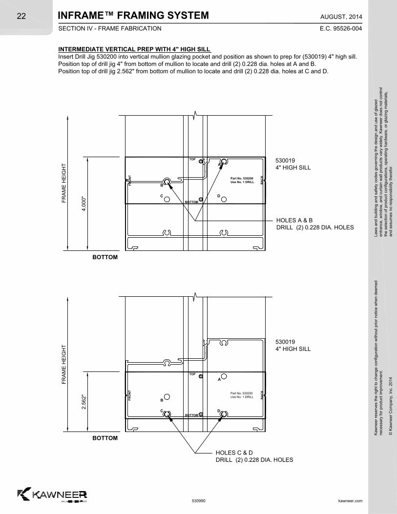
INTERMEDIATE VERTICAL PREP WITH 4" HIGH SILLInsert Drill Jig 530200 into vertical mullion glazing pocket and position as shown to prep for (530019) 4" high sill.Position top of drill jig 4" from bottom of mullion to locate and drill (2) 0.228 dia. holes at A and B.Position top of drill jig 2.562" from bottom of mullion to locate and drill (2) 0.228 dia. holes at C and D.
BOTTOM
C
FR
ON
T
B
BOTTOM
BA
CK
TOP
D
Part No. 530200Use No. 1 DRILL
A
4.0
00"
HOLES A & BDRILL (2) 0.228 DIA. HOLES
C
FR
ON
T
B
BOTTOM
BA
CK
TOP
D
Part No. 530200Use No. 1 DRILL
A
2.5
62"
HOLES C & DDRILL (2) 0.228 DIA. HOLES
5300194" HIGH SILL
5300194" HIGH SILL
BOTTOM
FR
AM
E H
EIG
HT
FR
AM
E H
EIG
HT
SECTION IV - FRAME FABRICATION
INFRAME™ FRAMING SYSTEMK
awne
er r
eser
ves
the
righ
t to
cha
nge
conf
igur
atio
n w
ithou
t pr
ior
notic
e w
hen
deem
edn
eces
sary
for
pro
duct
imp
rove
men
t.
© K
awne
er C
ompa
ny,
Inc.
201
4
Law
s an
d bu
ildin
g a
nd s
afet
y co
des
gove
rnin
g th
e de
sign
and
use
of g
laze
de
ntra
nce,
win
dow
, a
nd c
urta
in w
all p
rod
ucts
var
y w
ide
ly.
Ka
wn
eer
does
not
con
trol
the
sel
ectio
n o
f pr
oduc
t co
nfig
urat
ions
, op
erat
ing
hard
wa
re,
or g
lazi
ng m
ater
ials
,a
nd a
ssum
es n
o re
spon
sibi
lity
ther
efor
.23
kawneer.com
E.C. 95526-004
AUGUST, 2014
530990
2.4
38"
0.228 DIA. (2) PLACES0.188"530015
PARTITION SILL
1.7
57"
530010 SHOWN530016 SIMILAR
530011SILL
5300194" HIGH SILL
2.4
38"
0.228 DIA. (2) PLACES0.188"
1.7
81"
530010 SHOWN530016 SIMILAR
530016HEAD
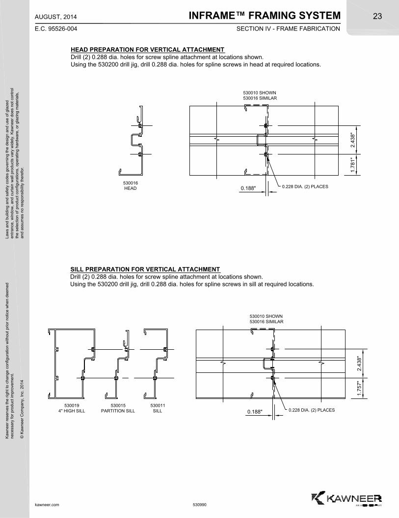
HEAD PREPARATION FOR VERTICAL ATTACHMENTDrill (2) 0.288 dia. holes for screw spline attachment at locations shown.Using the 530200 drill jig, drill 0.288 dia. holes for spline screws in head at required locations.
SILL PREPARATION FOR VERTICAL ATTACHMENTDrill (2) 0.288 dia. holes for screw spline attachment at locations shown.Using the 530200 drill jig, drill 0.288 dia. holes for spline screws in sill at required locations.
SECTION IV - FRAME FABRICATION
INFRAME™ FRAMING SYSTEM
kawneer.com
24
E.C. 95526-004
AUGUST, 2014
Kaw
neer
res
erve
s th
e rig
ht
to c
hang
e co
nfig
urat
ion
with
out
prio
r no
tice
whe
n de
emed
nec
essa
ry f
or p
rodu
ct im
pro
vem
ent.
© K
awne
er C
ompa
ny,
Inc.
201
4
Law
s an
d bu
ildin
g a
nd s
afet
y co
des
gove
rnin
g th
e de
sign
and
use
of g
laze
de
ntra
nce,
win
dow
, a
nd c
urta
in w
all p
rod
ucts
var
y w
ide
ly.
Ka
wn
eer
does
not
con
trol
the
sel
ectio
n o
f pr
oduc
t co
nfig
urat
ions
, op
erat
ing
hard
wa
re,
or g
lazi
ng m
ater
ials
,a
nd a
ssum
es n
o re
spon
sibi
lity
ther
efor
.
530990
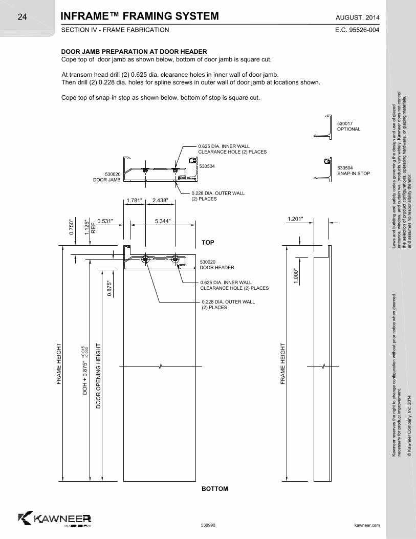
DOOR JAMB PREPARATION AT DOOR HEADERCope top of door jamb as shown below, bottom of door jamb is square cut.
At transom head drill (2) 0.625 dia. clearance holes in inner wall of door jamb.Then drill (2) 0.228 dia. holes for spline screws in outer wall of door jamb at locations shown.
Cope top of snap-in stop as shown below, bottom of stop is square cut.
1.1
25"
RE
F. 0.531"
TOP
BOTTOM
1.781" 2.438"
0.7
50"
0.8
75"
DO
H +
0.8
75"
+0
.015
-0.0
00
DO
OR
OP
EN
ING
HE
IGH
T
FR
AM
E H
EIG
HT
0.625 DIA. INNER WALLCLEARANCE HOLE (2) PLACES
0.228 DIA. OUTER WALL(2) PLACES
FR
AM
E H
EIG
HT
1.201"
1.0
00"
0.625 DIA. INNER WALLCLEARANCE HOLE (2) PLACES
0.228 DIA. OUTER WALL(2) PLACES
530504SNAP-IN STOP530020
DOOR JAMB
530504
5.344"
530020DOOR HEADER
530017OPTIONAL
SECTION IV - FRAME FABRICATION
INFRAME™ FRAMING SYSTEMK
awne
er r
eser
ves
the
righ
t to
cha
nge
conf
igur
atio
n w
ithou
t pr
ior
notic
e w
hen
deem
edn
eces
sary
for
pro
duct
imp
rove
men
t.
© K
awne
er C
ompa
ny,
Inc.
201
4
Law
s an
d bu
ildin
g a
nd s
afet
y co
des
gove
rnin
g th
e de
sign
and
use
of g
laze
de
ntra
nce,
win
dow
, a
nd c
urta
in w
all p
rod
ucts
var
y w
ide
ly.
Ka
wn
eer
does
not
con
trol
the
sel
ectio
n o
f pr
oduc
t co
nfig
urat
ions
, op
erat
ing
hard
wa
re,
or g
lazi
ng m
ater
ials
,a
nd a
ssum
es n
o re
spon
sibi
lity
ther
efor
.25
kawneer.com
E.C. 95526-004
AUGUST, 2014
530990
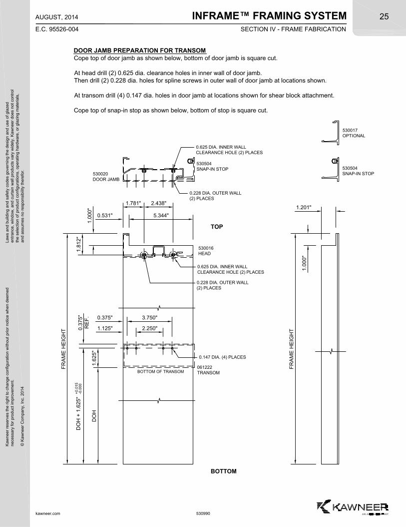
DOOR JAMB PREPARATION FOR TRANSOMCope top of door jamb as shown below, bottom of door jamb is square cut.
At head drill (2) 0.625 dia. clearance holes in inner wall of door jamb.Then drill (2) 0.228 dia. holes for spline screws in outer wall of door jamb at locations shown.
At transom drill (4) 0.147 dia. holes in door jamb at locations shown for shear block attachment.
Cope top of snap-in stop as shown below, bottom of stop is square cut.
0.3
75"
RE
F. 0.375" 3.750"
BOTTOM OF TRANSOM
1.6
25"
DO
H
DO
H +
1.6
25"
+0
.015
-0.0
001
.812
"
0.531"
TOP
1.781" 2.438"
530504SNAP-IN STOP
1.125" 2.250"
1.0
00"
BOTTOM
0.625 DIA. INNER WALLCLEARANCE HOLE (2) PLACES
0.228 DIA. OUTER WALL(2) PLACES
FR
AM
E H
EIG
HT
FR
AM
E H
EIG
HT
1.201"
1.0
00"
0.147 DIA. (4) PLACES
530504SNAP-IN STOP
0.625 DIA. INNER WALLCLEARANCE HOLE (2) PLACES
0.228 DIA. OUTER WALL(2) PLACES
530016HEAD
061222TRANSOM
530020DOOR JAMB
5.344"
530017OPTIONAL
SECTION IV - FRAME FABRICATION
INFRAME™ FRAMING SYSTEM
kawneer.com
26
E.C. 95526-004
AUGUST, 2014
Kaw
neer
res
erve
s th
e rig
ht
to c
hang
e co
nfig
urat
ion
with
out
prio
r no
tice
whe
n de
emed
nec
essa
ry f
or p
rodu
ct im
pro
vem
ent.
© K
awne
er C
ompa
ny,
Inc.
201
4
Law
s an
d bu
ildin
g a
nd s
afet
y co
des
gove
rnin
g th
e de
sign
and
use
of g
laze
de
ntra
nce,
win
dow
, a
nd c
urta
in w
all p
rod
ucts
var
y w
ide
ly.
Ka
wn
eer
does
not
con
trol
the
sel
ectio
n o
f pr
oduc
t co
nfig
urat
ions
, op
erat
ing
hard
wa
re,
or g
lazi
ng m
ater
ials
,a
nd a
ssum
es n
o re
spon
sibi
lity
ther
efor
.
530990
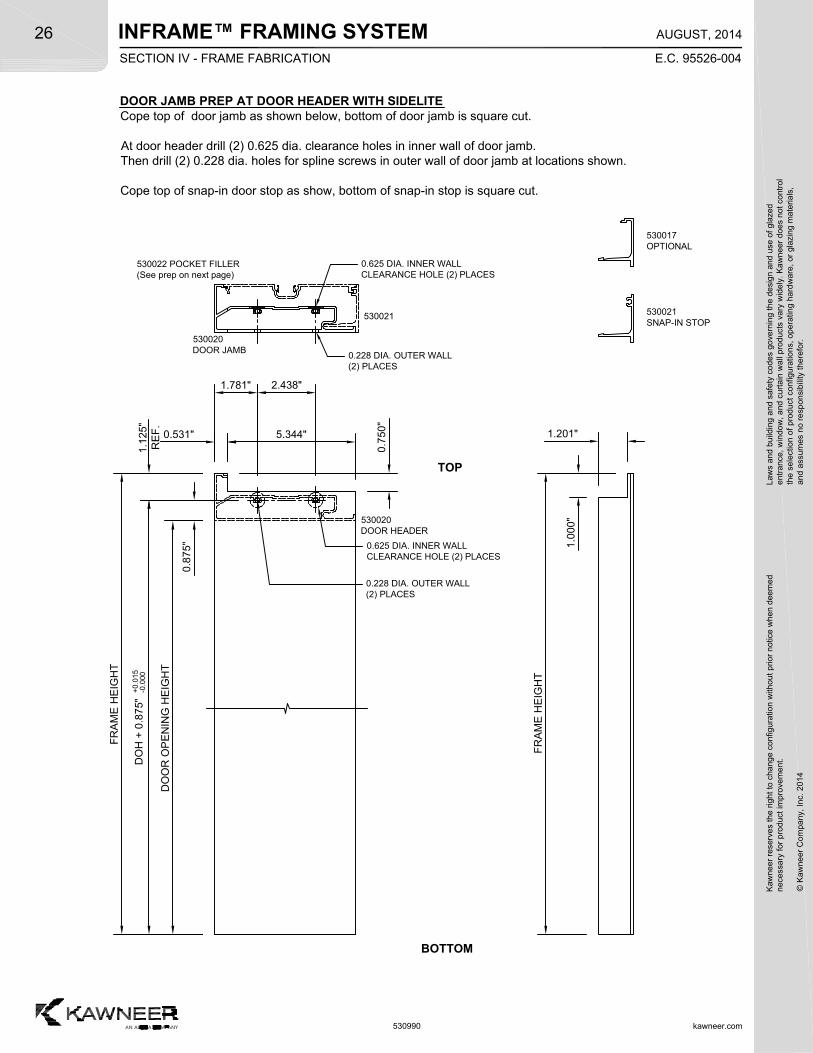
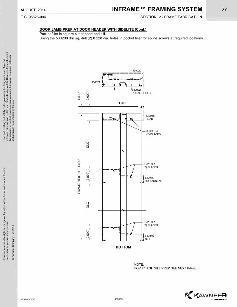
DOOR JAMB PREP AT DOOR HEADER WITH SIDELITECope top of door jamb as shown below, bottom of door jamb is square cut.
At door header drill (2) 0.625 dia. clearance holes in inner wall of door jamb.Then drill (2) 0.228 dia. holes for spline screws in outer wall of door jamb at locations shown.
Cope top of snap-in door stop as show, bottom of snap-in stop is square cut.
1.1
25"
RE
F.
0.531"
TOP
BOTTOM
1.781" 2.438"
0.8
75"
DO
H +
0.8
75"
+0
.015
-0.0
00
DO
OR
OP
EN
ING
HE
IGH
T
FR
AM
E H
EIG
HT
0.625 DIA. INNER WALLCLEARANCE HOLE (2) PLACES
0.228 DIA. OUTER WALL(2) PLACES
530022 POCKET FILLER(See prep on next page)
530021
530020DOOR JAMB
0.625 DIA. INNER WALLCLEARANCE HOLE (2) PLACES
0.228 DIA. OUTER WALL(2) PLACES
5.344"
0.7
50"
530020DOOR HEADER
1.0
00"
FR
AM
E H
EIG
HT
1.201"
530021SNAP-IN STOP
530017OPTIONAL
SECTION IV - FRAME FABRICATION
INFRAME™ FRAMING SYSTEMK
awne
er r
eser
ves
the
righ
t to
cha
nge
conf
igur
atio
n w
ithou
t pr
ior
notic
e w
hen
deem
edn
eces
sary
for
pro
duct
imp
rove
men
t.
© K
awne
er C
ompa
ny,
Inc.
201
4
Law
s an
d bu
ildin
g a
nd s
afet
y co
des
gove
rnin
g th
e de
sign
and
use
of g
laze
de
ntra
nce,
win
dow
, a
nd c
urta
in w
all p
rod
ucts
var
y w
ide
ly.
Ka
wn
eer
does
not
con
trol
the
sel
ectio
n o
f pr
oduc
t co
nfig
urat
ions
, op
erat
ing
hard
wa
re,
or g
lazi
ng m
ater
ials
,a
nd a
ssum
es n
o re
spon
sibi
lity
ther
efor
.27
kawneer.com
E.C. 95526-004
AUGUST, 2014
530990
DOOR JAMB PREP AT DOOR HEADER WITH SIDELITE (Cont.)Pocket filler is square cut at head and sill.Using the 530200 drill jig, drill (2) 0.228 dia. holes in pocket filler for spline screws at required locations.
TOP
BOTTOM
FR
AM
E H
EIG
HT
- 1
.00
0"
530022POCKET FILLER
2.0
00"
DLO
0.228 DIA.(2) PLACES
530020
530021
530016HORIZONTAL
530016SILL
0.228 DIA.(2) PLACES
1.0
00"
0.228 DIA.(2) PLACES
530016HEAD
NOTE:FOR 4" HIGH SILL PREP SEE NEXT PAGE.
DLO
2.0
00"
2.0
00"
SECTION IV - FRAME FABRICATION
INFRAME™ FRAMING SYSTEM
kawneer.com
28
E.C. 95526-004
AUGUST, 2014
Kaw
neer
res
erve
s th
e rig
ht
to c
hang
e co
nfig
urat
ion
with
out
prio
r no
tice
whe
n de
emed
nec
essa
ry f
or p
rodu
ct im
pro
vem
ent.
© K
awne
er C
ompa
ny,
Inc.
201
4
Law
s an
d bu
ildin
g a
nd s
afet
y co
des
gove
rnin
g th
e de
sign
and
use
of g
laze
de
ntra
nce,
win
dow
, a
nd c
urta
in w
all p
rod
ucts
var
y w
ide
ly.
Ka
wn
eer
does
not
con
trol
the
sel
ectio
n o
f pr
oduc
t co
nfig
urat
ions
, op
erat
ing
hard
wa
re,
or g
lazi
ng m
ater
ials
,a
nd a
ssum
es n
o re
spon
sibi
lity
ther
efor
.
530990
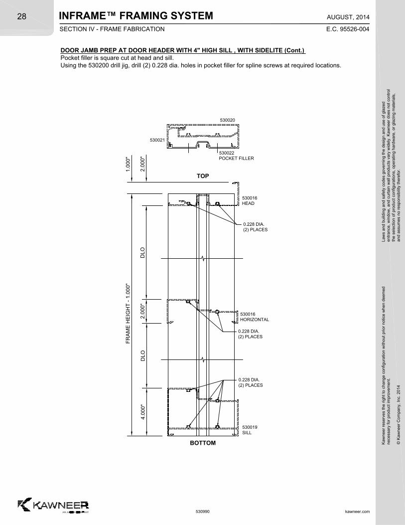
DOOR JAMB PREP AT DOOR HEADER WITH 4" HIGH SILL , WITH SIDELITE (Cont.)Pocket filler is square cut at head and sill.Using the 530200 drill jig, drill (2) 0.228 dia. holes in pocket filler for spline screws at required locations.
TOP
BOTTOM
FR
AM
E H
EIG
HT
- 1
.00
0"
0.228 DIA.(2) PLACES
2.0
00"
DLO
4.0
00"
0.228 DIA.(2) PLACES
1.0
00"
0.228 DIA.(2) PLACES
530016HEAD
530022POCKET FILLER
530020
530021
530016HORIZONTAL
530019SILL
DLO
2.0
00"
SECTION IV - FRAME FABRICATION
INFRAME™ FRAMING SYSTEMK
awne
er r
eser
ves
the
righ
t to
cha
nge
conf
igur
atio
n w
ithou
t pr
ior
notic
e w
hen
deem
edn
eces
sary
for
pro
duct
imp
rove
men
t.
© K
awne
er C
ompa
ny,
Inc.
201
4
Law
s an
d bu
ildin
g a
nd s
afet
y co
des
gove
rnin
g th
e de
sign
and
use
of g
laze
de
ntra
nce,
win
dow
, a
nd c
urta
in w
all p
rod
ucts
var
y w
ide
ly.
Ka
wn
eer
does
not
con
trol
the
sel
ectio
n o
f pr
oduc
t co
nfig
urat
ions
, op
erat
ing
hard
wa
re,
or g
lazi
ng m
ater
ials
,a
nd a
ssum
es n
o re
spon
sibi
lity
ther
efor
.29
kawneer.com
E.C. 95526-007
MARCH, 2015
530990
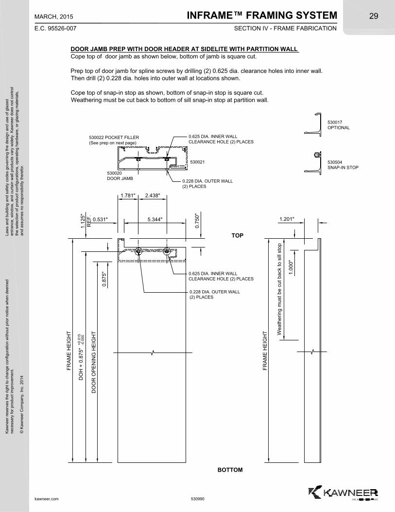
DOOR JAMB PREP WITH DOOR HEADER AT SIDELITE WITH PARTITION WALLCope top of door jamb as shown below, bottom of jamb is square cut.
Prep top of door jamb for spline screws by drilling (2) 0.625 dia. clearance holes into inner wall.Then drill (2) 0.228 dia. holes into outer wall at locations shown.
Cope top of snap-in stop as shown, bottom of snap-in stop is square cut.Weathering must be cut back to bottom of sill snap-in stop at partition wall.
1.1
25"
RE
F.
0.531"
TOP
BOTTOM
1.781" 2.438"0
.750
"
0.8
75"
DO
H +
0.8
75"
+0
.015
-0.0
00
DO
OR
OP
EN
ING
HE
IGH
T
FR
AM
E H
EIG
HT
0.625 DIA. INNER WALLCLEARANCE HOLE (2) PLACES
0.228 DIA. OUTER WALL(2) PLACES
530022 POCKET FILLER(See prep on next page)
530021
530020DOOR JAMB
Wea
ther
ing
mus
t be
cut
bac
k to
sill
sto
p
0.625 DIA. INNER WALLCLEARANCE HOLE (2) PLACES
0.228 DIA. OUTER WALL(2) PLACES
5.344"
1.0
00"
FR
AM
E H
EIG
HT
1.201"
530504SNAP-IN STOP
530017OPTIONAL
SECTION IV - FRAME FABRICATION
INFRAME™ FRAMING SYSTEM
kawneer.com
30
E.C. 95526-007
MARCH, 2015
Kaw
neer
res
erve
s th
e rig
ht
to c
hang
e co
nfig
urat
ion
with
out
prio
r no
tice
whe
n de
emed
nec
essa
ry f
or p
rodu
ct im
pro
vem
ent.
© K
awne
er C
ompa
ny,
Inc.
201
4
Law
s an
d bu
ildin
g a
nd s
afet
y co
des
gove
rnin
g th
e de
sign
and
use
of g
laze
de
ntra
nce,
win
dow
, a
nd c
urta
in w
all p
rod
ucts
var
y w
ide
ly.
Ka
wn
eer
does
not
con
trol
the
sel
ectio
n o
f pr
oduc
t co
nfig
urat
ions
, op
erat
ing
hard
wa
re,
or g
lazi
ng m
ater
ials
,a
nd a
ssum
es n
o re
spon
sibi
lity
ther
efor
.
530990
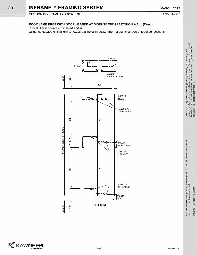
DOOR JAMB PREP WITH DOOR HEADER AT SIDELITE WITH PARTITION WALL (Cont.)Pocket filler is square cut at head and sill.Using the 530200 drill jig, drill (2) 0.228 dia. holes in pocket filler for spline screws at required locations.
TOP
BOTTOM
FR
AM
E H
EIG
HT
- 1
.75
0"
530022POCKET FILLER
0.228 DIA.(2) PLACES
2.0
00"
DLO
530016HORIZONTAL
530015SILL
0.7
50"
530021
530020
1.0
00"
0.228 DIA.(2) PLACES
530016HEAD
DLO
2.0
00"
2.0
00"
SECTION IV - FRAME FABRICATION
INFRAME™ FRAMING SYSTEMK
awne
er r
eser
ves
the
righ
t to
cha
nge
conf
igur
atio
n w
ithou
t pr
ior
notic
e w
hen
deem
edn
eces
sary
for
pro
duct
imp
rove
men
t.
© K
awne
er C
ompa
ny,
Inc.
201
4
Law
s an
d bu
ildin
g a
nd s
afet
y co
des
gove
rnin
g th
e de
sign
and
use
of g
laze
de
ntra
nce,
win
dow
, a
nd c
urta
in w
all p
rod
ucts
var
y w
ide
ly.
Ka
wn
eer
does
not
con
trol
the
sel
ectio
n o
f pr
oduc
t co
nfig
urat
ions
, op
erat
ing
hard
wa
re,
or g
lazi
ng m
ater
ials
,a
nd a
ssum
es n
o re
spon
sibi
lity
ther
efor
.31
kawneer.com
E.C. 95526-007
MARCH, 2015
530990
530022 POCKET FILLER(See prep on next page)
530021
530020DOOR JAMB
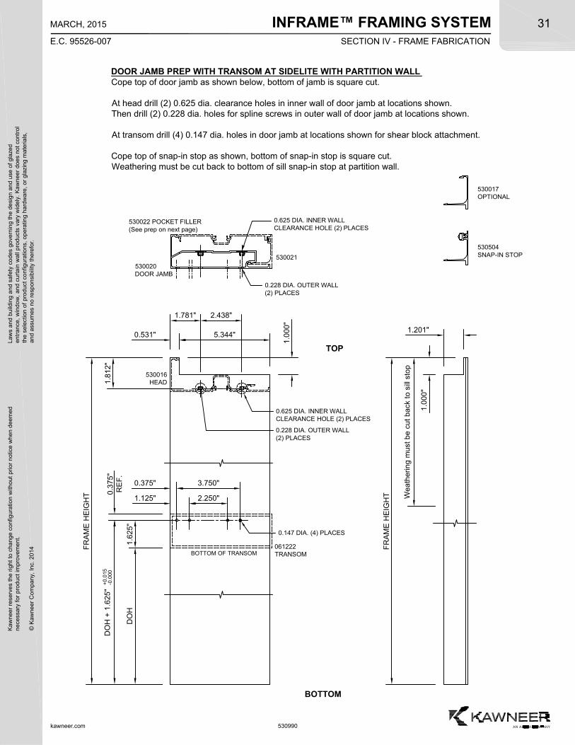
DOOR JAMB PREP WITH TRANSOM AT SIDELITE WITH PARTITION WALLCope top of door jamb as shown below, bottom of jamb is square cut.
At head drill (2) 0.625 dia. clearance holes in inner wall of door jamb at locations shown.Then drill (2) 0.228 dia. holes for spline screws in outer wall of door jamb at locations shown.
At transom drill (4) 0.147 dia. holes in door jamb at locations shown for shear block attachment.
Cope top of snap-in stop as shown, bottom of snap-in stop is square cut.Weathering must be cut back to bottom of sill snap-in stop at partition wall.
0.3
75"
RE
F.
0.375" 3.750"
BOTTOM OF TRANSOM
1.6
25"
DO
H
DO
H +
1.6
25"
+0
.015
-0.0
001
.812
"
0.531"
TOP
1.781" 2.438"
1.125" 2.250"
1.0
00"
BOTTOM
0.625 DIA. INNER WALLCLEARANCE HOLE (2) PLACES
0.228 DIA. OUTER WALL(2) PLACES
FR
AM
E H
EIG
HT
0.147 DIA. (4) PLACES
0.625 DIA. INNER WALLCLEARANCE HOLE (2) PLACES
0.228 DIA. OUTER WALL(2) PLACES
530016HEAD
061222TRANSOM
5.344"
Wea
ther
ing
mus
t be
cut
bac
k to
sill
sto
p
1.0
00"
FR
AM
E H
EIG
HT
1.201"
530504SNAP-IN STOP
530017OPTIONAL
SECTION IV - FRAME FABRICATION
INFRAME™ FRAMING SYSTEM
kawneer.com
32
E.C. 95526-007
MARCH, 2015
Kaw
neer
res
erve
s th
e rig
ht
to c
hang
e co
nfig
urat
ion
with
out
prio
r no
tice
whe
n de
emed
nec
essa
ry f
or p
rodu
ct im
pro
vem
ent.
© K
awne
er C
ompa
ny,
Inc.
201
4
Law
s an
d bu
ildin
g a
nd s
afet
y co
des
gove
rnin
g th
e de
sign
and
use
of g
laze
de
ntra
nce,
win
dow
, a
nd c
urta
in w
all p
rod
ucts
var
y w
ide
ly.
Ka
wn
eer
does
not
con
trol
the
sel
ectio
n o
f pr
oduc
t co
nfig
urat
ions
, op
erat
ing
hard
wa
re,
or g
lazi
ng m
ater
ials
,a
nd a
ssum
es n
o re
spon
sibi
lity
ther
efor
.
530990
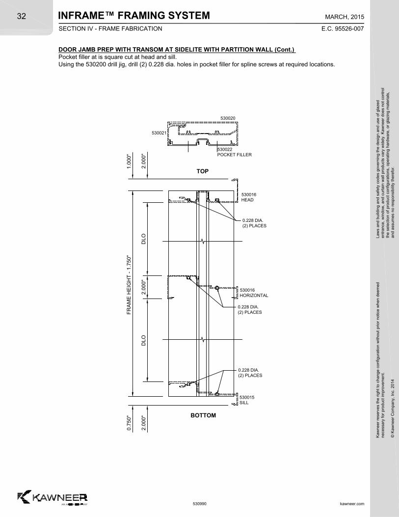
DOOR JAMB PREP WITH TRANSOM AT SIDELITE WITH PARTITION WALL (Cont.)Pocket filler at is square cut at head and sill.Using the 530200 drill jig, drill (2) 0.228 dia. holes in pocket filler for spline screws at required locations.
TOP
BOTTOM
FR
AM
E H
EIG
HT
- 1
.75
0"
530022POCKET FILLER
0.228 DIA.(2) PLACES
2.0
00"
DLO
0.7
50"
530021
530020
1.0
00"
0.228 DIA.(2) PLACES
530016HEAD
DLO
0.228 DIA.(2) PLACES
2.0
00"
2.0
00"
530015SILL
530016HORIZONTAL
SECTION IV - FRAME FABRICATION
INFRAME™ FRAMING SYSTEMK
awne
er r
eser
ves
the
righ
t to
cha
nge
conf
igur
atio
n w
ithou
t pr
ior
notic
e w
hen
deem
edn
eces
sary
for
pro
duct
imp
rove
men
t.
© K
awne
er C
ompa
ny,
Inc.
201
4
Law
s an
d bu
ildin
g a
nd s
afet
y co
des
gove
rnin
g th
e de
sign
and
use
of g
laze
de
ntra
nce,
win
dow
, a
nd c
urta
in w
all p
rod
ucts
var
y w
ide
ly.
Ka
wn
eer
does
not
con
trol
the
sel
ectio
n o
f pr
oduc
t co
nfig
urat
ions
, op
erat
ing
hard
wa
re,
or g
lazi
ng m
ater
ials
,a
nd a
ssum
es n
o re
spon
sibi
lity
ther
efor
.33
kawneer.com
E.C. 95526-006
DECEMBER, 2014
530990
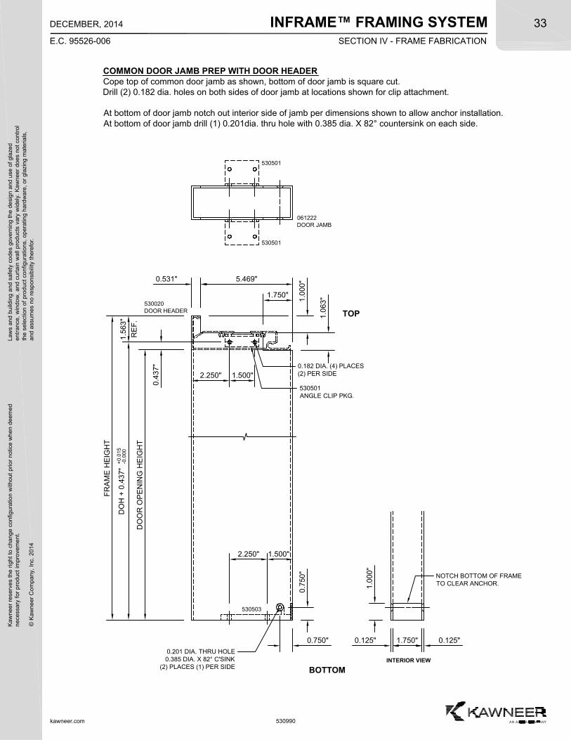
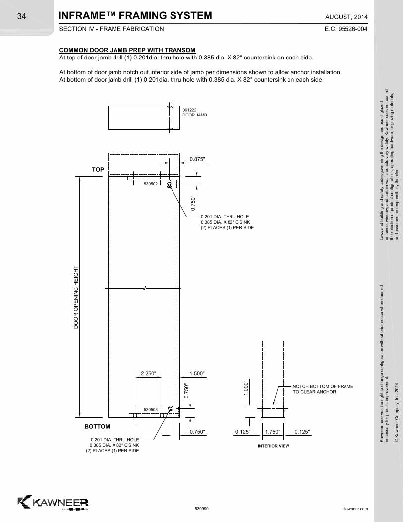
COMMON DOOR JAMB PREP WITH DOOR HEADERCope top of common door jamb as shown, bottom of door jamb is square cut.Drill (2) 0.182 dia. holes on both sides of door jamb at locations shown for clip attachment.
At bottom of door jamb notch out interior side of jamb per dimensions shown to allow anchor installation.At bottom of door jamb drill (1) 0.201dia. thru hole with 0.385 dia. X 82° countersink on each side.
TOP
0.531"
2.250" 1.500"
DO
OR
OP
EN
ING
HE
IGH
T
DO
H +
0.4
37"
+0
.015
-0.0
001
.563
"
RE
F.
0.7
50"
0.750" 1.750" 0.125"0.125"
0.4
37"
BOTTOM
0.182 DIA. (4) PLACES(2) PER SIDE
1.0
00"
NOTCH BOTTOM OF FRAMETO CLEAR ANCHOR.
530503
530501
530501
INTERIOR VIEW
0.201 DIA. THRU HOLE0.385 DIA. X 82° C'SINK
(2) PLACES (1) PER SIDE
1.0
00"
FR
AM
E H
EIG
HT
2.250" 1.500"
061222DOOR JAMB
530020DOOR HEADER
5.469"
530501ANGLE CLIP PKG.
SECTION IV - FRAME FABRICATION
1.0
63"1.750"
INFRAME™ FRAMING SYSTEM
kawneer.com
34
E.C. 95526-004
AUGUST, 2014
Kaw
neer
res
erve
s th
e rig
ht
to c
hang
e co
nfig
urat
ion
with
out
prio
r no
tice
whe
n de
emed
nec
essa
ry f
or p
rodu
ct im
pro
vem
ent.
© K
awne
er C
ompa
ny,
Inc.
201
4
Law
s an
d bu
ildin
g a
nd s
afet
y co
des
gove
rnin
g th
e de
sign
and
use
of g
laze
de
ntra
nce,
win
dow
, a
nd c
urta
in w
all p
rod
ucts
var
y w
ide
ly.
Ka
wn
eer
does
not
con
trol
the
sel
ectio
n o
f pr
oduc
t co
nfig
urat
ions
, op
erat
ing
hard
wa
re,
or g
lazi
ng m
ater
ials
,a
nd a
ssum
es n
o re
spon
sibi
lity
ther
efor
.
530990
COMMON DOOR JAMB PREP WITH TRANSOMAt top of door jamb drill (1) 0.201dia. thru hole with 0.385 dia. X 82° countersink on each side.
At bottom of door jamb notch out interior side of jamb per dimensions shown to allow anchor installation.At bottom of door jamb drill (1) 0.201dia. thru hole with 0.385 dia. X 82° countersink on each side.
0.7
50"
0.750" 1.750" 0.125"0.125"BOTTOM
NOTCH BOTTOM OF FRAMETO CLEAR ANCHOR.
530503
INTERIOR VIEW
0.201 DIA. THRU HOLE0.385 DIA. X 82° C'SINK
(2) PLACES (1) PER SIDE
1.0
00"
0.875"
0.7
50"
DO
OR
OP
EN
ING
HE
IGH
T
2.250" 1.500"
TOP
530502
061222DOOR JAMB
0.201 DIA. THRU HOLE0.385 DIA. X 82° C'SINK(2) PLACES (1) PER SIDE
SECTION IV - FRAME FABRICATION
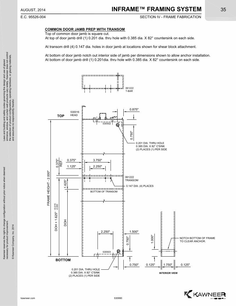
INFRAME™ FRAMING SYSTEMK
awne
er r
eser
ves
the
righ
t to
cha
nge
conf
igur
atio
n w
ithou
t pr
ior
notic
e w
hen
deem
edn
eces
sary
for
pro
duct
imp
rove
men
t.
© K
awne
er C
ompa
ny,
Inc.
201
4
Law
s an
d bu
ildin
g a
nd s
afet
y co
des
gove
rnin
g th
e de
sign
and
use
of g
laze
de
ntra
nce,
win
dow
, a
nd c
urta
in w
all p
rod
ucts
var
y w
ide
ly.
Ka
wn
eer
does
not
con
trol
the
sel
ectio
n o
f pr
oduc
t co
nfig
urat
ions
, op
erat
ing
hard
wa
re,
or g
lazi
ng m
ater
ials
,a
nd a
ssum
es n
o re
spon
sibi
lity
ther
efor
.35
kawneer.com
E.C. 95526-004
AUGUST, 2014
530990
COMMON DOOR JAMB PREP WITH TRANSOMTop of common door jamb is square cut.At top of door jamb drill (1) 0.201 dia. thru hole with 0.385 dia. X 82° countersink on each side.
At transom drill (4) 0.147 dia. holes in door jamb at locations shown for shear block attachment.
At bottom of door jamb notch out interior side of jamb per dimensions shown to allow anchor installation.At bottom of door jamb drill (1) 0.201dia. thru hole with 0.385 dia. X 82° countersink on each side.
0.7
50"
0.750" 1.750" 0.125"0.125"
BOTTOM
NOTCH BOTTOM OF FRAMETO CLEAR ANCHOR.
530503
INTERIOR VIEW
0.201 DIA. THRU HOLE0.385 DIA. X 82° C'SINK
(2) PLACES (1) PER SIDE
1.0
00"
0.3
75"
RE
F. 0.375" 3.750"
BOTTOM OF TRANSOM
1.6
25"
DO
H
DO
H +
1.6
25"
+0
.015
-0.0
00
1.125" 2.250"
0.147 DIA. (4) PLACES
TOP
0.875"
0.7
50"
FR
AM
E H
EIG
HT
- 2
.00
0"
530502
2.250" 1.500"
061222T-BAR
530016HEAD
0.201 DIA. THRU HOLE0.385 DIA. X 82° C'SINK(2) PLACES (1) PER SIDE
061222TRANSOM
SECTION IV - FRAME FABRICATION
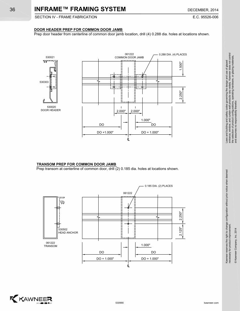
INFRAME™ FRAMING SYSTEM
kawneer.com
36
E.C. 95526-006
DECEMBER, 2014
Kaw
neer
res
erve
s th
e rig
ht
to c
hang
e co
nfig
urat
ion
with
out
prio
r no
tice
whe
n de
emed
nec
essa
ry f
or p
rodu
ct im
pro
vem
ent.
© K
awne
er C
ompa
ny,
Inc.
201
4
Law
s an
d bu
ildin
g a
nd s
afet
y co
des
gove
rnin
g th
e de
sign
and
use
of g
laze
de
ntra
nce,
win
dow
, a
nd c
urta
in w
all p
rod
ucts
var
y w
ide
ly.
Ka
wn
eer
does
not
con
trol
the
sel
ectio
n o
f pr
oduc
t co
nfig
urat
ions
, op
erat
ing
hard
wa
re,
or g
lazi
ng m
ater
ials
,a
nd a
ssum
es n
o re
spon
sibi
lity
ther
efor
.
530990
TRANSOM PREP FOR COMMON DOOR JAMBPrep transom at centerline of common door, drill (2) 0.185 dia. holes at locations shown.
061222
061222TRANSOM
2.1
25"
2.2
50"
DO
DO + 1.000"
DO
DO + 1.000"
CL
530502HEAD ANCHOR
1.000"
0.185 DIA. (2) PLACES
DOOR HEADER PREP FOR COMMON DOOR JAMBPrep door header from centerline of common door jamb location, drill (4) 0.288 dia. holes at locations shown.
530020DOOR HEADER
DO
DO +1.000"
DO
DO + 1.000"
CL
2.000" 2.000"
0.288 DIA. (4) PLACES
2.2
50"
1.5
00"
1.000"
061222COMMON DOOR JAMB
SECTION IV - FRAME FABRICATION
530021
530303
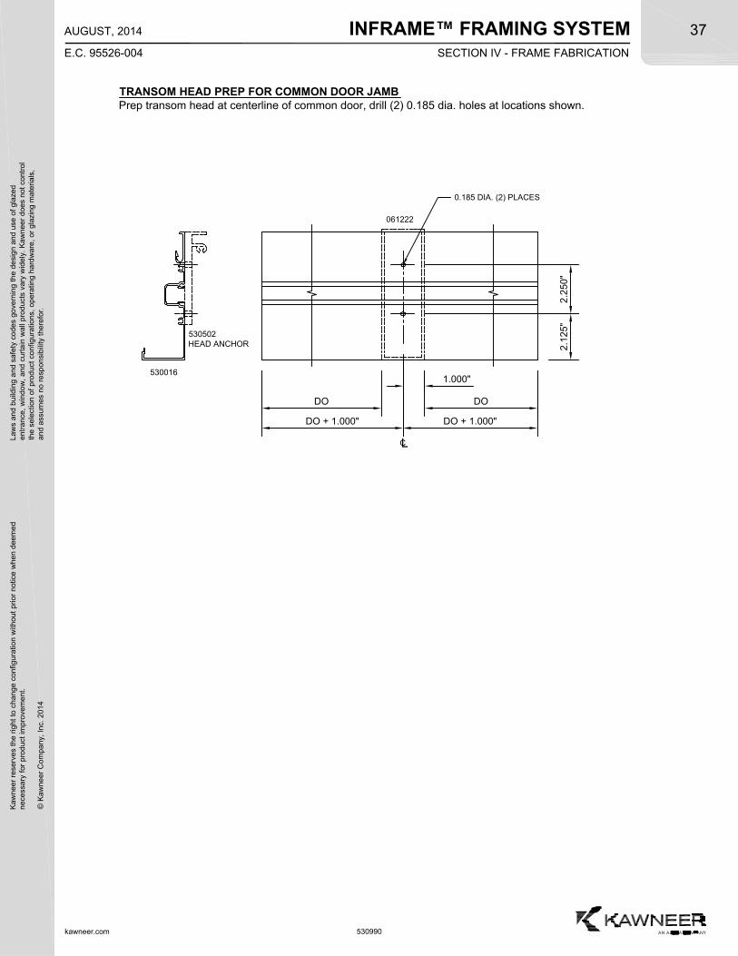
INFRAME™ FRAMING SYSTEMK
awne
er r
eser
ves
the
righ
t to
cha
nge
conf
igur
atio
n w
ithou
t pr
ior
notic
e w
hen
deem
edn
eces
sary
for
pro
duct
imp
rove
men
t.
© K
awne
er C
ompa
ny,
Inc.
201
4
Law
s an
d bu
ildin
g a
nd s
afet
y co
des
gove
rnin
g th
e de
sign
and
use
of g
laze
de
ntra
nce,
win
dow
, a
nd c
urta
in w
all p
rod
ucts
var
y w
ide
ly.
Ka
wn
eer
does
not
con
trol
the
sel
ectio
n o
f pr
oduc
t co
nfig
urat
ions
, op
erat
ing
hard
wa
re,
or g
lazi
ng m
ater
ials
,a
nd a
ssum
es n
o re
spon
sibi
lity
ther
efor
.37
kawneer.com
E.C. 95526-004
AUGUST, 2014
530990
061222
530016
2.1
25"
2.2
50"
530502HEAD ANCHOR
DO
DO + 1.000"
DO
DO + 1.000"
CL
1.000"
0.185 DIA. (2) PLACES
TRANSOM HEAD PREP FOR COMMON DOOR JAMBPrep transom head at centerline of common door, drill (2) 0.185 dia. holes at locations shown.
SECTION IV - FRAME FABRICATION
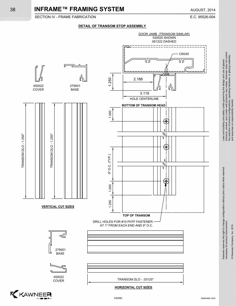
INFRAME™ FRAMING SYSTEM
kawneer.com
38
E.C. 95526-004
AUGUST, 2014
Kaw
neer
res
erve
s th
e rig
ht
to c
hang
e co
nfig
urat
ion
with
out
prio
r no
tice
whe
n de
emed
nec
essa
ry f
or p
rodu
ct im
pro
vem
ent.
© K
awne
er C
ompa
ny,
Inc.
201
4
Law
s an
d bu
ildin
g a
nd s
afet
y co
des
gove
rnin
g th
e de
sign
and
use
of g
laze
de
ntra
nce,
win
dow
, a
nd c
urta
in w
all p
rod
ucts
var
y w
ide
ly.
Ka
wn
eer
does
not
con
trol
the
sel
ectio
n o
f pr
oduc
t co
nfig
urat
ions
, op
erat
ing
hard
wa
re,
or g
lazi
ng m
ater
ials
,a
nd a
ssum
es n
o re
spon
sibi
lity
ther
efor
.
530990
3.119
BOTTOM OF TRANSOM HEAD
VERTICAL CUT SIZES
HORIZONTAL CUT SIZES
DETAIL OF TRANSOM STOP ASSEMBLY
DOOR JAMB (TRANSOM SIMILAR)530020 SHOWN061222 DASHED
450022COVER
279001BASE
1.2
50
HOLE CENTERLINE
TOP OF TRANSOM
1.0
001
.000
9"
O.C
. (T
YP
.)
TR
AN
SO
M D
LO -
1.2
50"
450022COVER
279001BASE
TRANSOM DLO - .03125"
DRILL HOLES FOR #10 FHTF FASTENERAT 1" FROM EACH END AND 9" O.C.
1.2
50
2.188
128345T
RA
NS
OM
DLO
- 1
.250
"
SECTION IV - FRAME FABRICATION
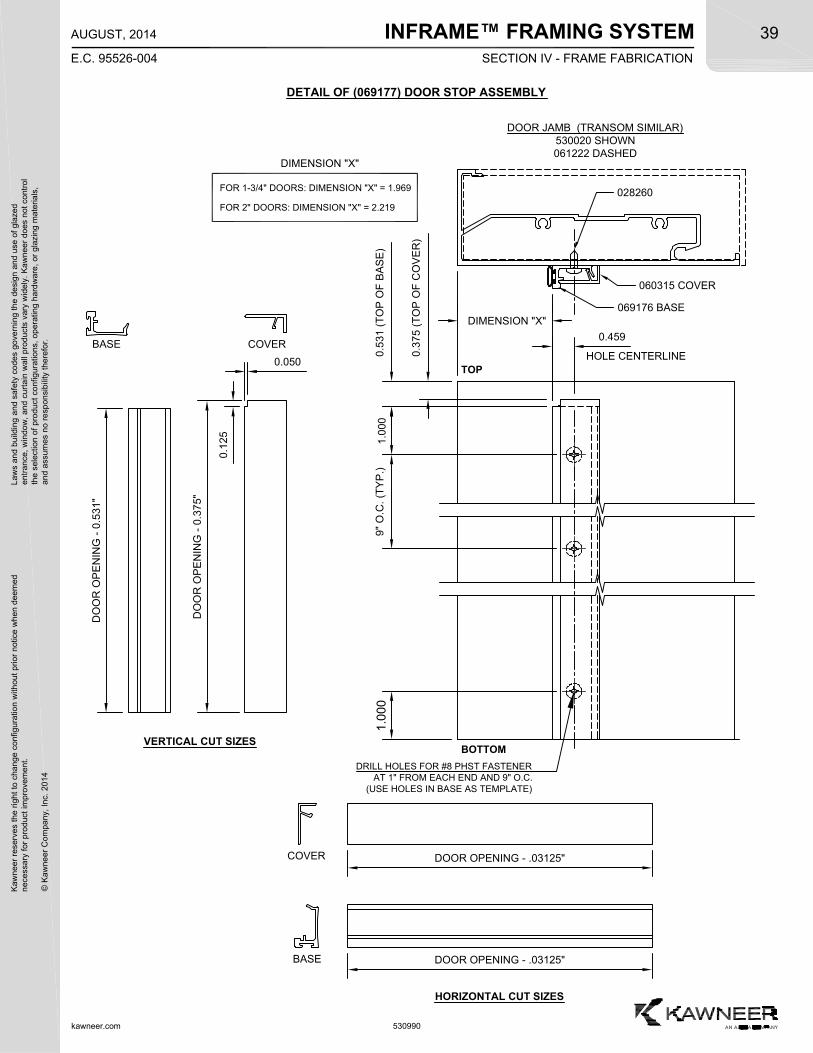
INFRAME™ FRAMING SYSTEMK
awne
er r
eser
ves
the
righ
t to
cha
nge
conf
igur
atio
n w
ithou
t pr
ior
notic
e w
hen
deem
edn
eces
sary
for
pro
duct
imp
rove
men
t.
© K
awne
er C
ompa
ny,
Inc.
201
4
Law
s an
d bu
ildin
g a
nd s
afet
y co
des
gove
rnin
g th
e de
sign
and
use
of g
laze
de
ntra
nce,
win
dow
, a
nd c
urta
in w
all p
rod
ucts
var
y w
ide
ly.
Ka
wn
eer
does
not
con
trol
the
sel
ectio
n o
f pr
oduc
t co
nfig
urat
ions
, op
erat
ing
hard
wa
re,
or g
lazi
ng m
ater
ials
,a
nd a
ssum
es n
o re
spon
sibi
lity
ther
efor
.39
kawneer.com
E.C. 95526-004
AUGUST, 2014
530990
COVERBASE
DETAIL OF (069177) DOOR STOP ASSEMBLY
DIMENSION "X"
BOTTOM
DOOR JAMB (TRANSOM SIMILAR)530020 SHOWN061222 DASHED
060315 COVER
069176 BASE
TOP0
.531
(T
OP
OF
BA
SE
)1
.000
9"
O.C
. (T
YP
.)1
.000
0.459
0.3
75 (
TO
P O
F C
OV
ER
)
DO
OR
OP
EN
ING
- 0
.531
"
DO
OR
OP
EN
ING
- 0
.375
"
DIMENSION "X"
0.050
0.1
25
VERTICAL CUT SIZES
COVER
BASE DOOR OPENING - .03125"
DOOR OPENING - .03125"
HORIZONTAL CUT SIZES
HOLE CENTERLINE
DRILL HOLES FOR #8 PHST FASTENERAT 1" FROM EACH END AND 9" O.C.
(USE HOLES IN BASE AS TEMPLATE)
FOR 1-3/4" DOORS: DIMENSION "X" = 1.969
FOR 2" DOORS: DIMENSION "X" = 2.219
028260
SECTION IV - FRAME FABRICATION
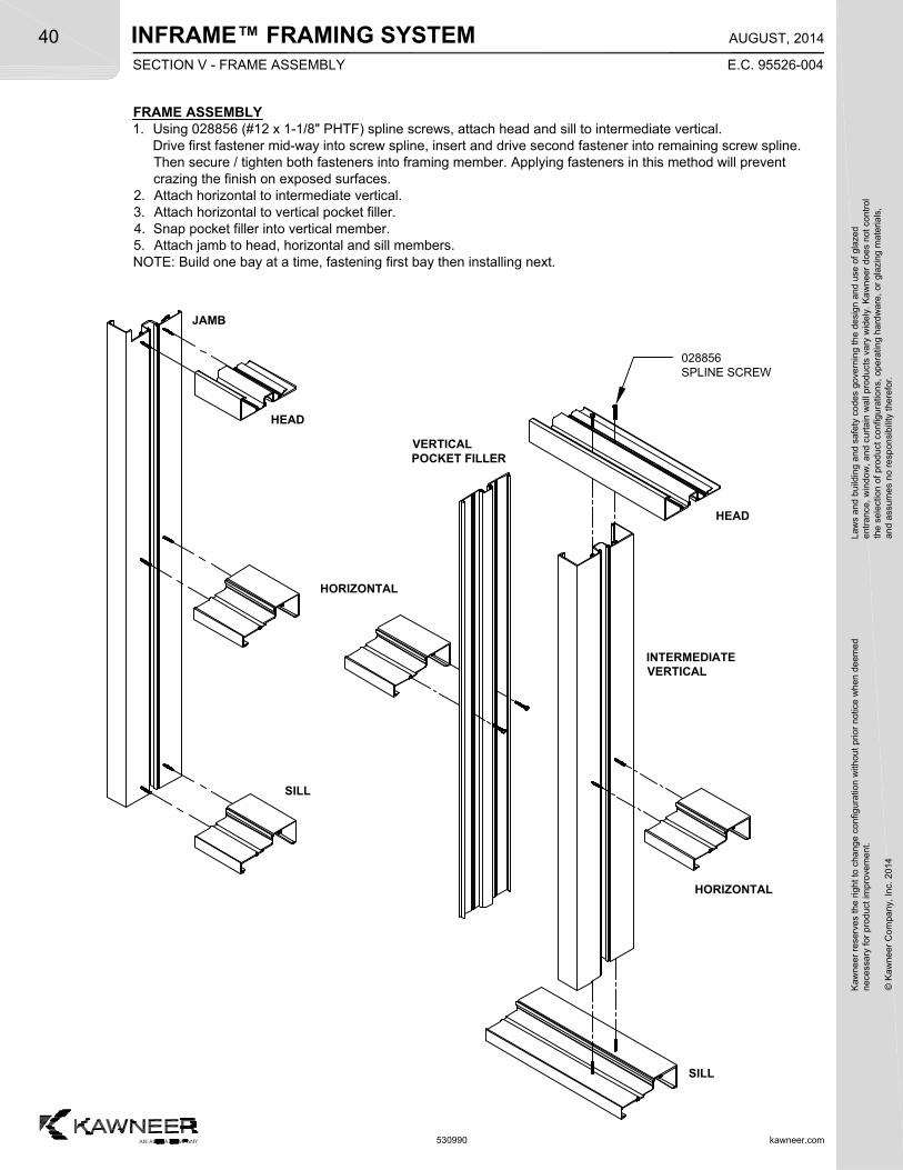
INFRAME™ FRAMING SYSTEM
kawneer.com
40
E.C. 95526-004
AUGUST, 2014
Kaw
neer
res
erve
s th
e rig
ht
to c
hang
e co
nfig
urat
ion
with
out
prio
r no
tice
whe
n de
emed
nec
essa
ry f
or p
rodu
ct im
pro
vem
ent.
© K
awne
er C
ompa
ny,
Inc.
201
4
Law
s an
d bu
ildin
g a
nd s
afet
y co
des
gove
rnin
g th
e de
sign
and
use
of g
laze
de
ntra
nce,
win
dow
, a
nd c
urta
in w
all p
rod
ucts
var
y w
ide
ly.
Ka
wn
eer
does
not
con
trol
the
sel
ectio
n o
f pr
oduc
t co
nfig
urat
ions
, op
erat
ing
hard
wa
re,
or g
lazi
ng m
ater
ials
,a
nd a
ssum
es n
o re
spon
sibi
lity
ther
efor
.
530990
FRAME ASSEMBLY1. Using 028856 (#12 x 1-1/8" PHTF) spline screws, attach head and sill to intermediate vertical.
Drive first fastener mid-way into screw spline, insert and drive second fastener into remaining screw spline.Then secure / tighten both fasteners into framing member. Applying fasteners in this method will preventcrazing the finish on exposed surfaces.
2. Attach horizontal to intermediate vertical.3. Attach horizontal to vertical pocket filler.4. Snap pocket filler into vertical member.5. Attach jamb to head, horizontal and sill members.NOTE: Build one bay at a time, fastening first bay then installing next.
JAMB
HEAD
HORIZONTAL
SILL
HEAD
INTERMEDIATEVERTICAL
HORIZONTAL
SILL
VERTICALPOCKET FILLER
028856SPLINE SCREW
SECTION V - FRAME ASSEMBLY
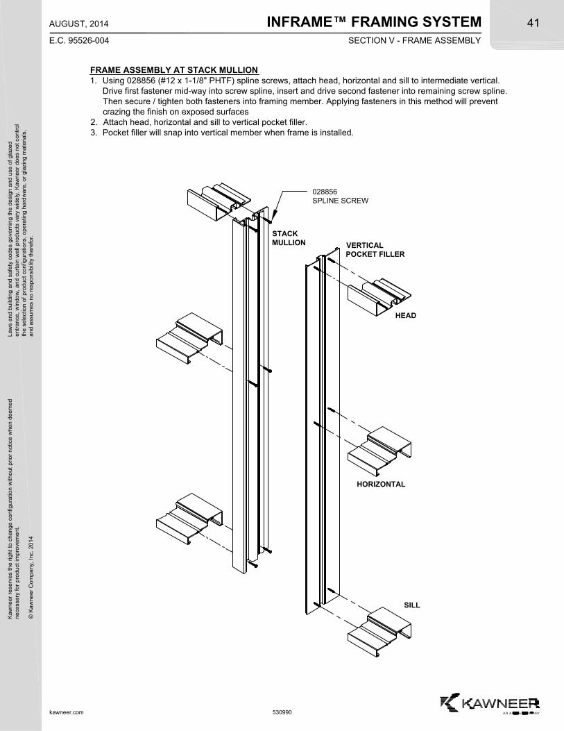
INFRAME™ FRAMING SYSTEMK
awne
er r
eser
ves
the
righ
t to
cha
nge
conf
igur
atio
n w
ithou
t pr
ior
notic
e w
hen
deem
edn
eces
sary
for
pro
duct
imp
rove
men
t.
© K
awne
er C
ompa
ny,
Inc.
201
4
Law
s an
d bu
ildin
g a
nd s
afet
y co
des
gove
rnin
g th
e de
sign
and
use
of g
laze
de
ntra
nce,
win
dow
, a
nd c
urta
in w
all p
rod
ucts
var
y w
ide
ly.
Ka
wn
eer
does
not
con
trol
the
sel
ectio
n o
f pr
oduc
t co
nfig
urat
ions
, op
erat
ing
hard
wa
re,
or g
lazi
ng m
ater
ials
,a
nd a
ssum
es n
o re
spon
sibi
lity
ther
efor
.41
kawneer.com
E.C. 95526-004
AUGUST, 2014
530990
FRAME ASSEMBLY AT STACK MULLION1. Using 028856 (#12 x 1-1/8" PHTF) spline screws, attach head, horizontal and sill to intermediate vertical.
Drive first fastener mid-way into screw spline, insert and drive second fastener into remaining screw spline.Then secure / tighten both fasteners into framing member. Applying fasteners in this method will preventcrazing the finish on exposed surfaces
2. Attach head, horizontal and sill to vertical pocket filler.3. Pocket filler will snap into vertical member when frame is installed.
VERTICALPOCKET FILLER
028856SPLINE SCREW
HEAD
SILL
HORIZONTAL
STACKMULLION
SECTION V - FRAME ASSEMBLY
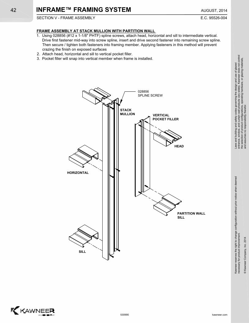
INFRAME™ FRAMING SYSTEM
kawneer.com
42
E.C. 95526-004
AUGUST, 2014
Kaw
neer
res
erve
s th
e rig
ht
to c
hang
e co
nfig
urat
ion
with
out
prio
r no
tice
whe
n de
emed
nec
essa
ry f
or p
rodu
ct im
pro
vem
ent.
© K
awne
er C
ompa
ny,
Inc.
201
4
Law
s an
d bu
ildin
g a
nd s
afet
y co
des
gove
rnin
g th
e de
sign
and
use
of g
laze
de
ntra
nce,
win
dow
, a
nd c
urta
in w
all p
rod
ucts
var
y w
ide
ly.
Ka
wn
eer
does
not
con
trol
the
sel
ectio
n o
f pr
oduc
t co
nfig
urat
ions
, op
erat
ing
hard
wa
re,
or g
lazi
ng m
ater
ials
,a
nd a
ssum
es n
o re
spon
sibi
lity
ther
efor
.
530990
FRAME ASSEMBLY AT STACK MULLION WITH PARTITION WALL1. Using 028856 (#12 x 1-1/8" PHTF) spline screws, attach head, horizontal and sill to intermediate vertical.
Drive first fastener mid-way into screw spline, insert and drive second fastener into remaining screw spline.Then secure / tighten both fasteners into framing member. Applying fasteners in this method will preventcrazing the finish on exposed surfaces
2. Attach head, horizontal and sill to vertical pocket filler.3. Pocket filler will snap into vertical member when frame is installed.
VERTICALPOCKET FILLER
028856SPLINE SCREW
HEAD
PARTITION WALLSILL
HORIZONTAL
STACKMULLION
SILL
SECTION V - FRAME ASSEMBLY
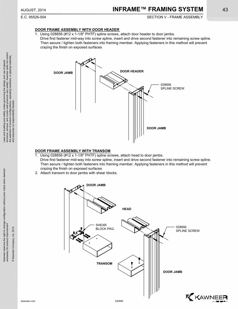
INFRAME™ FRAMING SYSTEMK
awne
er r
eser
ves
the
righ
t to
cha
nge
conf
igur
atio
n w
ithou
t pr
ior
notic
e w
hen
deem
edn
eces
sary
for
pro
duct
imp
rove
men
t.
© K
awne
er C
ompa
ny,
Inc.
201
4
Law
s an
d bu
ildin
g a
nd s
afet
y co
des
gove
rnin
g th
e de
sign
and
use
of g
laze
de
ntra
nce,
win
dow
, a
nd c
urta
in w
all p
rod
ucts
var
y w
ide
ly.
Ka
wn
eer
does
not
con
trol
the
sel
ectio
n o
f pr
oduc
t co
nfig
urat
ions
, op
erat
ing
hard
wa
re,
or g
lazi
ng m
ater
ials
,a
nd a
ssum
es n
o re
spon
sibi
lity
ther
efor
.43
kawneer.com
E.C. 95526-004
AUGUST, 2014
530990
DOOR FRAME ASSEMBLY WITH DOOR HEADER1. Using 028856 (#12 x 1-1/8" PHTF) spline screws, attach door header to door jambs.
Drive first fastener mid-way into screw spline, insert and drive second fastener into remaining screw spline.Then secure / tighten both fasteners into framing member. Applying fasteners in this method will preventcrazing the finish on exposed surfaces
028856SPLINE SCREW
DOOR JAMB
DOOR JAMB
DOOR HEADER
DOOR FRAME ASSEMBLY WITH TRANSOM1. Using 028856 (#12 x 1-1/8" PHTF) spline screws, attach head to door jambs.
Drive first fastener mid-way into screw spline, insert and drive second fastener into remaining screw spline.Then secure / tighten both fasteners into framing member. Applying fasteners in this method will preventcrazing the finish on exposed surfaces
2. Attach transom to door jambs with shear blocks.
028856SPLINE SCREW
DOOR JAMB
DOOR JAMB
HEAD
TRANSOM
SHEARBLOCK PKG.
SECTION V - FRAME ASSEMBLY
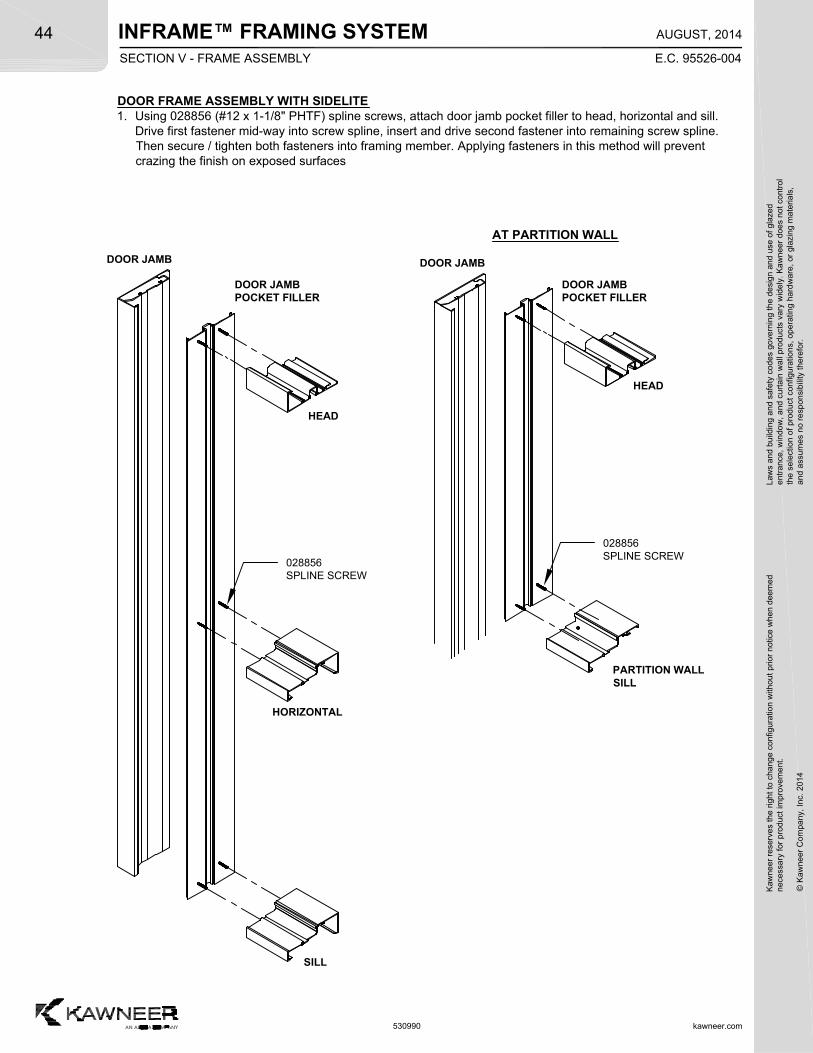
INFRAME™ FRAMING SYSTEM
kawneer.com
44
E.C. 95526-004
AUGUST, 2014
Kaw
neer
res
erve
s th
e rig
ht
to c
hang
e co
nfig
urat
ion
with
out
prio
r no
tice
whe
n de
emed
nec
essa
ry f
or p
rodu
ct im
pro
vem
ent.
© K
awne
er C
ompa
ny,
Inc.
201
4
Law
s an
d bu
ildin
g a
nd s
afet
y co
des
gove
rnin
g th
e de
sign
and
use
of g
laze
de
ntra
nce,
win
dow
, a
nd c
urta
in w
all p
rod
ucts
var
y w
ide
ly.
Ka
wn
eer
does
not
con
trol
the
sel
ectio
n o
f pr
oduc
t co
nfig
urat
ions
, op
erat
ing
hard
wa
re,
or g
lazi
ng m
ater
ials
,a
nd a
ssum
es n
o re
spon
sibi
lity
ther
efor
.
530990
DOOR FRAME ASSEMBLY WITH SIDELITE1. Using 028856 (#12 x 1-1/8" PHTF) spline screws, attach door jamb pocket filler to head, horizontal and sill.
Drive first fastener mid-way into screw spline, insert and drive second fastener into remaining screw spline.Then secure / tighten both fasteners into framing member. Applying fasteners in this method will preventcrazing the finish on exposed surfaces
SILL
PARTITION WALLSILL
DOOR JAMB DOOR JAMB
DOOR JAMBPOCKET FILLER
HORIZONTAL
DOOR JAMBPOCKET FILLER
HEAD
028856SPLINE SCREW
HEAD
028856SPLINE SCREW
AT PARTITION WALL
SECTION V - FRAME ASSEMBLY
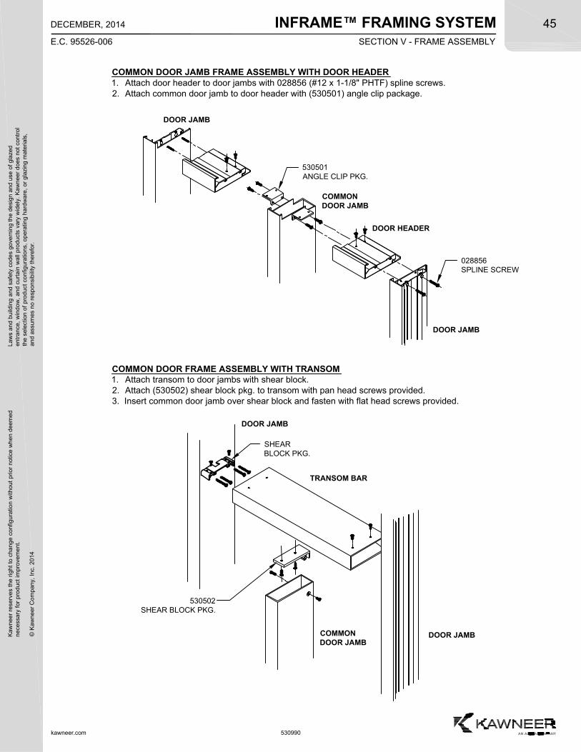
INFRAME™ FRAMING SYSTEMK
awne
er r
eser
ves
the
righ
t to
cha
nge
conf
igur
atio
n w
ithou
t pr
ior
notic
e w
hen
deem
edn
eces
sary
for
pro
duct
imp
rove
men
t.
© K
awne
er C
ompa
ny,
Inc.
201
4
Law
s an
d bu
ildin
g a
nd s
afet
y co
des
gove
rnin
g th
e de
sign
and
use
of g
laze
de
ntra
nce,
win
dow
, a
nd c
urta
in w
all p
rod
ucts
var
y w
ide
ly.
Ka
wn
eer
does
not
con
trol
the
sel
ectio
n o
f pr
oduc
t co
nfig
urat
ions
, op
erat
ing
hard
wa
re,
or g
lazi
ng m
ater
ials
,a
nd a
ssum
es n
o re
spon
sibi
lity
ther
efor
.45
kawneer.com
E.C. 95526-006
DECEMBER, 2014
530990
COMMON DOOR JAMB FRAME ASSEMBLY WITH DOOR HEADER1. Attach door header to door jambs with 028856 (#12 x 1-1/8" PHTF) spline screws.2. Attach common door jamb to door header with (530501) angle clip package.
028856SPLINE SCREW
DOOR JAMB
DOOR JAMB
DOOR HEADER
530501ANGLE CLIP PKG.
COMMONDOOR JAMB
COMMONDOOR JAMB
COMMON DOOR FRAME ASSEMBLY WITH TRANSOM1. Attach transom to door jambs with shear block.2. Attach (530502) shear block pkg. to transom with pan head screws provided.3. Insert common door jamb over shear block and fasten with flat head screws provided.
DOOR JAMB
DOOR JAMB
TRANSOM BAR
SHEARBLOCK PKG.
530502SHEAR BLOCK PKG.
SECTION V - FRAME ASSEMBLY
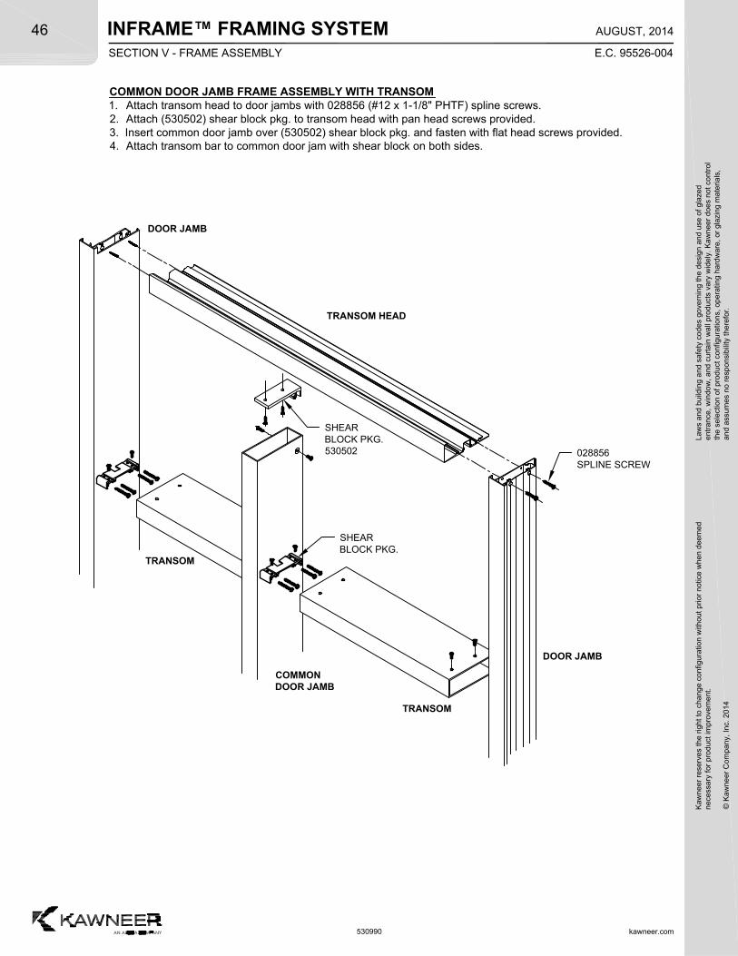
INFRAME™ FRAMING SYSTEM
kawneer.com
46
E.C. 95526-004
AUGUST, 2014
Kaw
neer
res
erve
s th
e rig
ht
to c
hang
e co
nfig
urat
ion
with
out
prio
r no
tice
whe
n de
emed
nec
essa
ry f
or p
rodu
ct im
pro
vem
ent.
© K
awne
er C
ompa
ny,
Inc.
201
4
Law
s an
d bu
ildin
g a
nd s
afet
y co
des
gove
rnin
g th
e de
sign
and
use
of g
laze
de
ntra
nce,
win
dow
, a
nd c
urta
in w
all p
rod
ucts
var
y w
ide
ly.
Ka
wn
eer
does
not
con
trol
the
sel
ectio
n o
f pr
oduc
t co
nfig
urat
ions
, op
erat
ing
hard
wa
re,
or g
lazi
ng m
ater
ials
,a
nd a
ssum
es n
o re
spon
sibi
lity
ther
efor
.
530990
COMMON DOOR JAMB FRAME ASSEMBLY WITH TRANSOM1. Attach transom head to door jambs with 028856 (#12 x 1-1/8" PHTF) spline screws.2. Attach (530502) shear block pkg. to transom head with pan head screws provided.3. Insert common door jamb over (530502) shear block pkg. and fasten with flat head screws provided.4. Attach transom bar to common door jam with shear block on both sides.
COMMONDOOR JAMB
DOOR JAMB
SHEARBLOCK PKG.
028856SPLINE SCREW
DOOR JAMB
TRANSOM HEAD
SHEARBLOCK PKG.530502
TRANSOM
TRANSOM
SECTION V - FRAME ASSEMBLY
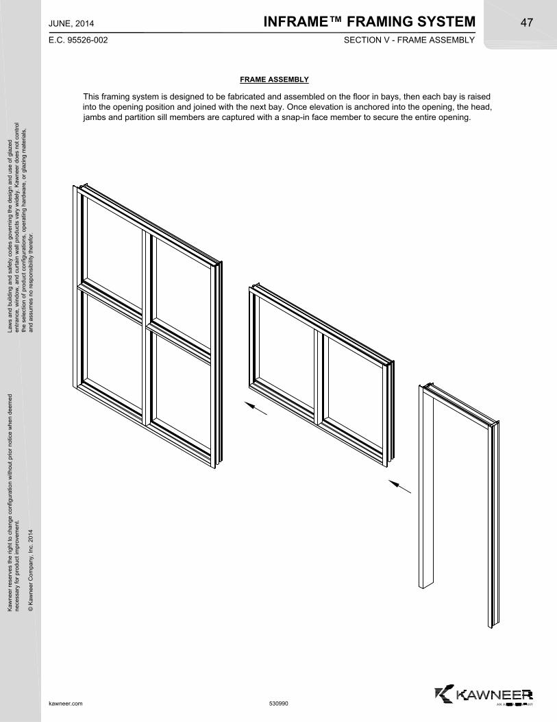
INFRAME™ FRAMING SYSTEMK
awne
er r
eser
ves
the
righ
t to
cha
nge
conf
igur
atio
n w
ithou
t pr
ior
notic
e w
hen
deem
edn
eces
sary
for
pro
duct
imp
rove
men
t.
© K
awne
er C
ompa
ny,
Inc.
201
4
Law
s an
d bu
ildin
g a
nd s
afet
y co
des
gove
rnin
g th
e de
sign
and
use
of g
laze
de
ntra
nce,
win
dow
, a
nd c
urta
in w
all p
rod
ucts
var
y w
ide
ly.
Ka
wn
eer
does
not
con
trol
the
sel
ectio
n o
f pr
oduc
t co
nfig
urat
ions
, op
erat
ing
hard
wa
re,
or g
lazi
ng m
ater
ials
,a
nd a
ssum
es n
o re
spon
sibi
lity
ther
efor
.47
kawneer.com
E.C. 95526-002
JUNE, 2014
530990
This framing system is designed to be fabricated and assembled on the floor in bays, then each bay is raisedinto the opening position and joined with the next bay. Once elevation is anchored into the opening, the head,jambs and partition sill members are captured with a snap-in face member to secure the entire opening.
FRAME ASSEMBLY
SECTION V - FRAME ASSEMBLY
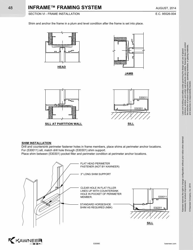
INFRAME™ FRAMING SYSTEM
kawneer.com
48
E.C. 95526-004
AUGUST, 2014
Kaw
neer
res
erve
s th
e rig
ht
to c
hang
e co
nfig
urat
ion
with
out
prio
r no
tice
whe
n de
emed
nec
essa
ry f
or p
rodu
ct im
pro
vem
ent.
© K
awne
er C
ompa
ny,
Inc.
201
4
Law
s an
d bu
ildin
g a
nd s
afet
y co
des
gove
rnin
g th
e de
sign
and
use
of g
laze
de
ntra
nce,
win
dow
, a
nd c
urta
in w
all p
rod
ucts
var
y w
ide
ly.
Ka
wn
eer
does
not
con
trol
the
sel
ectio
n o
f pr
oduc
t co
nfig
urat
ions
, op
erat
ing
hard
wa
re,
or g
lazi
ng m
ater
ials
,a
nd a
ssum
es n
o re
spon
sibi
lity
ther
efor
.
530990
Shim and anchor the frame in a plum and level condition after the frame is set into place.
HEAD
SILL AT PARTITION WALL
530301
530011
SILL
FLAT HEAD PERIMETERFASTENER (NOT BY KAWNEER)
3" LONG SHIM SUPPORT
CLEAR HOLE IN FLAT FILLERLINES UP WITH COUNTERSINKHOLE IN POCKET OF PERIMETERMEMBER.
STANDARD HORSESHOESHIM AS REQUIRED (NBK)
SHIM INSTALLATIONDrill and countersink perimeter fastener holes in frame members, place shims at perimeter anchor locations.For (530011) sill, match drill hole through (530301) shim support.Place shim between (530301) pocket filler and perimeter condition at perimeter anchor locations.
JAMB
530301
530011
SILL
SECTION VI - FRAME INSTALLATION
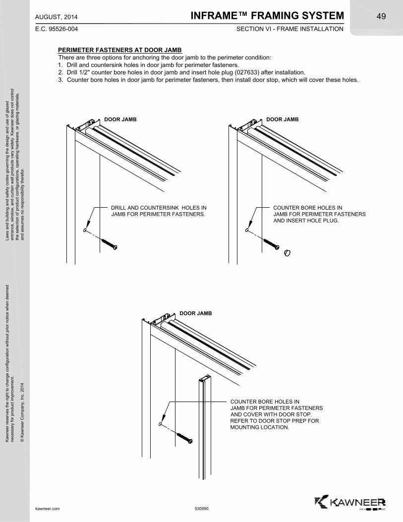
INFRAME™ FRAMING SYSTEMK
awne
er r
eser
ves
the
righ
t to
cha
nge
conf
igur
atio
n w
ithou
t pr
ior
notic
e w
hen
deem
edn
eces
sary
for
pro
duct
imp
rove
men
t.
© K
awne
er C
ompa
ny,
Inc.
201
4
Law
s an
d bu
ildin
g a
nd s
afet
y co
des
gove
rnin
g th
e de
sign
and
use
of g
laze
de
ntra
nce,
win
dow
, a
nd c
urta
in w
all p
rod
ucts
var
y w
ide
ly.
Ka
wn
eer
does
not
con
trol
the
sel
ectio
n o
f pr
oduc
t co
nfig
urat
ions
, op
erat
ing
hard
wa
re,
or g
lazi
ng m
ater
ials
,a
nd a
ssum
es n
o re
spon
sibi
lity
ther
efor
.49
kawneer.com
E.C. 95526-004
AUGUST, 2014
530990
PERIMETER FASTENERS AT DOOR JAMBThere are three options for anchoring the door jamb to the perimeter condition:1. Drill and countersink holes in door jamb for perimeter fasteners.2. Drill 1/2" counter bore holes in door jamb and insert hole plug (027633) after installation.3. Counter bore holes in door jamb for perimeter fasteners, then install door stop, which will cover these holes.
DOOR JAMB
DRILL AND COUNTERSINK HOLES INJAMB FOR PERIMETER FASTENERS.
DOOR JAMB
COUNTER BORE HOLES INJAMB FOR PERIMETER FASTENERSAND COVER WITH DOOR STOP.REFER TO DOOR STOP PREP FORMOUNTING LOCATION.
DOOR JAMB
COUNTER BORE HOLES INJAMB FOR PERIMETER FASTENERSAND INSERT HOLE PLUG.
SECTION VI - FRAME INSTALLATION
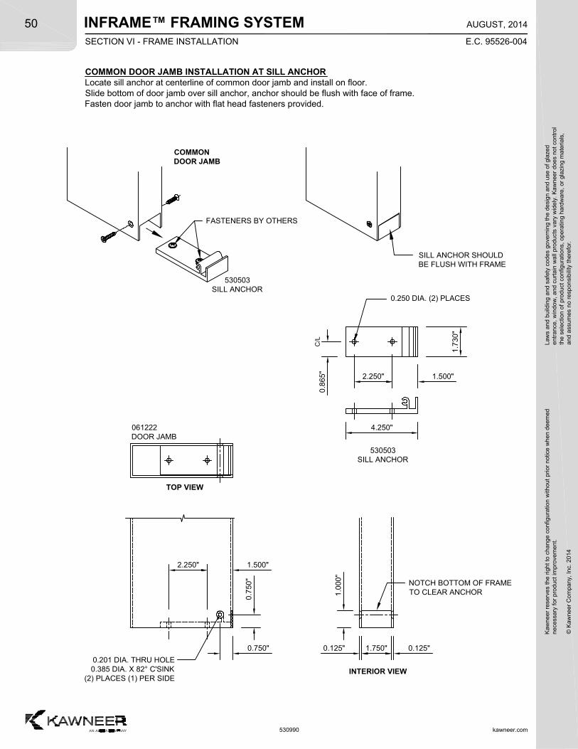
INFRAME™ FRAMING SYSTEM
kawneer.com
50
E.C. 95526-004
AUGUST, 2014
Kaw
neer
res
erve
s th
e rig
ht
to c
hang
e co
nfig
urat
ion
with
out
prio
r no
tice
whe
n de
emed
nec
essa
ry f
or p
rodu
ct im
pro
vem
ent.
© K
awne
er C
ompa
ny,
Inc.
201
4
Law
s an
d bu
ildin
g a
nd s
afet
y co
des
gove
rnin
g th
e de
sign
and
use
of g
laze
de
ntra
nce,
win
dow
, a
nd c
urta
in w
all p
rod
ucts
var
y w
ide
ly.
Ka
wn
eer
does
not
con
trol
the
sel
ectio
n o
f pr
oduc
t co
nfig
urat
ions
, op
erat
ing
hard
wa
re,
or g
lazi
ng m
ater
ials
,a
nd a
ssum
es n
o re
spon
sibi
lity
ther
efor
.
530990
COMMON DOOR JAMB INSTALLATION AT SILL ANCHORLocate sill anchor at centerline of common door jamb and install on floor.Slide bottom of door jamb over sill anchor, anchor should be flush with face of frame.Fasten door jamb to anchor with flat head fasteners provided.
0.7
50"
0.750" 1.750" 0.125"0.125"
NOTCH BOTTOM OF FRAMETO CLEAR ANCHOR
INTERIOR VIEW
0.201 DIA. THRU HOLE0.385 DIA. X 82° C'SINK
(2) PLACES (1) PER SIDE
1.0
00"
C/L
1.7
30"
2.250" 1.500"
4.250"
0.250 DIA. (2) PLACES
0.8
65"
2.250" 1.500"
061222DOOR JAMB
530503SILL ANCHOR
COMMONDOOR JAMB
530503SILL ANCHOR
TOP VIEW
SILL ANCHOR SHOULDBE FLUSH WITH FRAME
FASTENERS BY OTHERS
SECTION VI - FRAME INSTALLATION
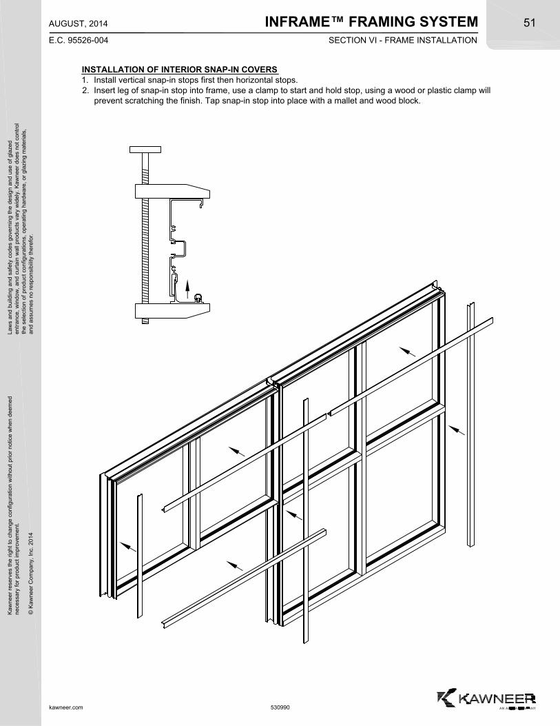
INFRAME™ FRAMING SYSTEMK
awne
er r
eser
ves
the
righ
t to
cha
nge
conf
igur
atio
n w
ithou
t pr
ior
notic
e w
hen
deem
edn
eces
sary
for
pro
duct
imp
rove
men
t.
© K
awne
er C
ompa
ny,
Inc.
201
4
Law
s an
d bu
ildin
g a
nd s
afet
y co
des
gove
rnin
g th
e de
sign
and
use
of g
laze
de
ntra
nce,
win
dow
, a
nd c
urta
in w
all p
rod
ucts
var
y w
ide
ly.
Ka
wn
eer
does
not
con
trol
the
sel
ectio
n o
f pr
oduc
t co
nfig
urat
ions
, op
erat
ing
hard
wa
re,
or g
lazi
ng m
ater
ials
,a
nd a
ssum
es n
o re
spon
sibi
lity
ther
efor
.51
kawneer.com
E.C. 95526-004
AUGUST, 2014
530990
INSTALLATION OF INTERIOR SNAP-IN COVERS1. Install vertical snap-in stops first then horizontal stops.2. Insert leg of snap-in stop into frame, use a clamp to start and hold stop, using a wood or plastic clamp will
prevent scratching the finish. Tap snap-in stop into place with a mallet and wood block.
SECTION VI - FRAME INSTALLATION
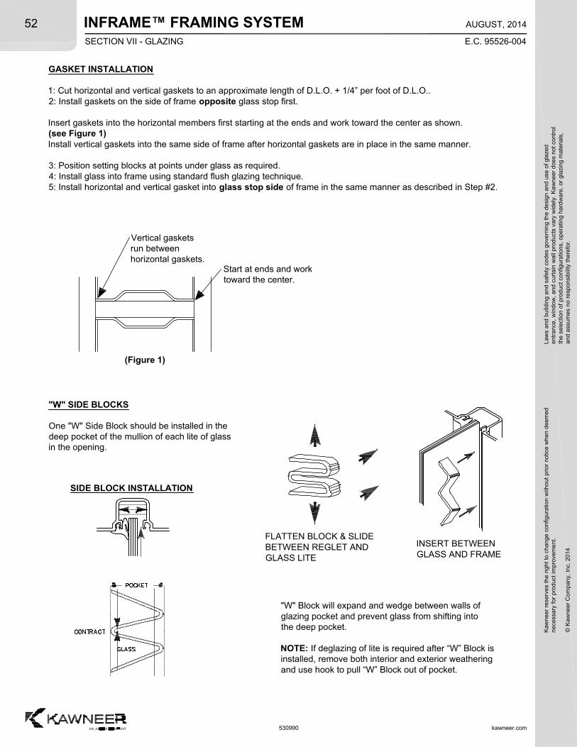
INFRAME™ FRAMING SYSTEM
kawneer.com
52
E.C. 95526-004
AUGUST, 2014
Kaw
neer
res
erve
s th
e rig
ht
to c
hang
e co
nfig
urat
ion
with
out
prio
r no
tice
whe
n de
emed
nec
essa
ry f
or p
rodu
ct im
pro
vem
ent.
© K
awne
er C
ompa
ny,
Inc.
201
4
Law
s an
d bu
ildin
g a
nd s
afet
y co
des
gove
rnin
g th
e de
sign
and
use
of g
laze
de
ntra
nce,
win
dow
, a
nd c
urta
in w
all p
rod
ucts
var
y w
ide
ly.
Ka
wn
eer
does
not
con
trol
the
sel
ectio
n o
f pr
oduc
t co
nfig
urat
ions
, op
erat
ing
hard
wa
re,
or g
lazi
ng m
ater
ials
,a
nd a
ssum
es n
o re
spon
sibi
lity
ther
efor
.
530990
"W" SIDE BLOCKS
One "W" Side Block should be installed in thedeep pocket of the mullion of each lite of glassin the opening.
FLATTEN BLOCK & SLIDEBETWEEN REGLET ANDGLASS LITE
INSERT BETWEENGLASS AND FRAME
"W" Block will expand and wedge between walls ofglazing pocket and prevent glass from shifting intothe deep pocket.
NOTE: If deglazing of lite is required after “W” Block isinstalled, remove both interior and exterior weatheringand use hook to pull “W” Block out of pocket.
GASKET INSTALLATION
1: Cut horizontal and vertical gaskets to an approximate length of D.L.O. + 1/4” per foot of D.L.O..2: Install gaskets on the side of frame opposite glass stop first.
Insert gaskets into the horizontal members first starting at the ends and work toward the center as shown.(see Figure 1)Install vertical gaskets into the same side of frame after horizontal gaskets are in place in the same manner.
3: Position setting blocks at points under glass as required.4: Install glass into frame using standard flush glazing technique.5: Install horizontal and vertical gasket into glass stop side of frame in the same manner as described in Step #2.
Vertical gasketsrun betweenhorizontal gaskets.
Start at ends and worktoward the center.
SIDE BLOCK INSTALLATION
(Figure 1)
SECTION VII - GLAZING
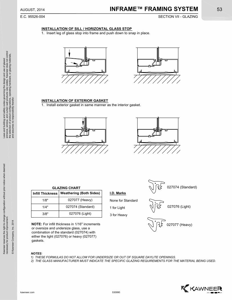
INFRAME™ FRAMING SYSTEMK
awne
er r
eser
ves
the
righ
t to
cha
nge
conf
igur
atio
n w
ithou
t pr
ior
notic
e w
hen
deem
edn
eces
sary
for
pro
duct
imp
rove
men
t.
© K
awne
er C
ompa
ny,
Inc.
201
4
Law
s an
d bu
ildin
g a
nd s
afet
y co
des
gove
rnin
g th
e de
sign
and
use
of g
laze
de
ntra
nce,
win
dow
, a
nd c
urta
in w
all p
rod
ucts
var
y w
ide
ly.
Ka
wn
eer
does
not
con
trol
the
sel
ectio
n o
f pr
oduc
t co
nfig
urat
ions
, op
erat
ing
hard
wa
re,
or g
lazi
ng m
ater
ials
,a
nd a
ssum
es n
o re
spon
sibi
lity
ther
efor
.53
kawneer.com
E.C. 95526-004
AUGUST, 2014
530990
INSTALLATION OF SILL / HORIZONTAL GLASS STOP1. Insert leg of glass stop into frame and push down to snap in place.
INSTALLATION OF EXTERIOR GASKET1. Install exterior gasket in same manner as the interior gasket.
SECTION VII - GLAZING
Infill Thickness Weathering (Both Sides)
027076 (Light)
027074 (Standard)
3/8"
1/4"
027077 (Heavy)1/8"
NOTES:1) THESE FORMULAS DO NOT ALLOW FOR UNDERSIZE OR OUT OF SQUARE DAYLITE OPENINGS.2) THE GLASS MANUFACTURER MUST INDICATE THE SPECIFIC GLAZING REQUIREMENTS FOR THE MATERIAL BEING USED.
NOTE: For infill thickness in 1/16" incrementsor oversize and undersize glass, use acombination of the standard (027074) witheither the light (027076) or heavy (027077)gaskets.
I.D. Marks
None for Standard
1 for Light
3 for Heavy
027077 (Heavy)
027074 (Standard)
027076 (Light)
GLAZING CHART
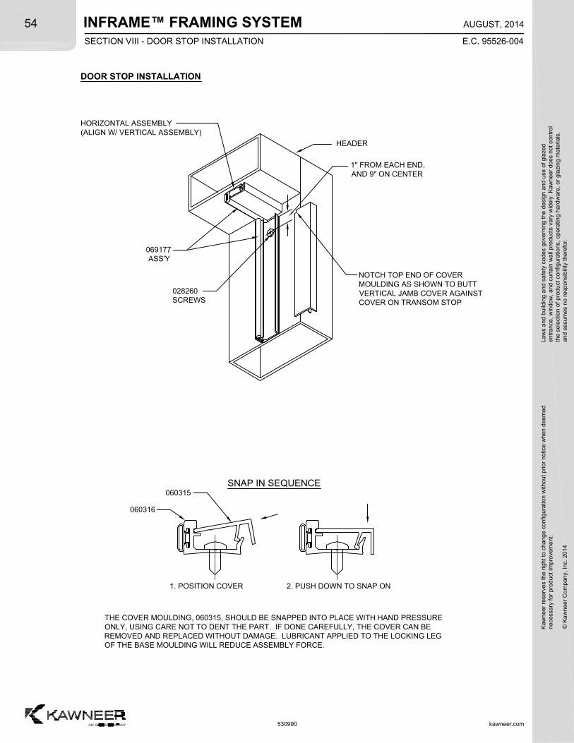
INFRAME™ FRAMING SYSTEM
kawneer.com
54
E.C. 95526-004
AUGUST, 2014
Kaw
neer
res
erve
s th
e rig
ht
to c
hang
e co
nfig
urat
ion
with
out
prio
r no
tice
whe
n de
emed
nec
essa
ry f
or p
rodu
ct im
pro
vem
ent.
© K
awne
er C
ompa
ny,
Inc.
201
4
Law
s an
d bu
ildin
g a
nd s
afet
y co
des
gove
rnin
g th
e de
sign
and
use
of g
laze
de
ntra
nce,
win
dow
, a
nd c
urta
in w
all p
rod
ucts
var
y w
ide
ly.
Ka
wn
eer
does
not
con
trol
the
sel
ectio
n o
f pr
oduc
t co
nfig
urat
ions
, op
erat
ing
hard
wa
re,
or g
lazi
ng m
ater
ials
,a
nd a
ssum
es n
o re
spon
sibi
lity
ther
efor
.
530990
DOOR STOP INSTALLATION
NOTCH TOP END OF COVERMOULDING AS SHOWN TO BUTTVERTICAL JAMB COVER AGAINSTCOVER ON TRANSOM STOP
069177 ASS'Y
HEADER
1" FROM EACH END,AND 9" ON CENTER
THE COVER MOULDING, 060315, SHOULD BE SNAPPED INTO PLACE WITH HAND PRESSUREONLY, USING CARE NOT TO DENT THE PART. IF DONE CAREFULLY, THE COVER CAN BEREMOVED AND REPLACED WITHOUT DAMAGE. LUBRICANT APPLIED TO THE LOCKING LEGOF THE BASE MOULDING WILL REDUCE ASSEMBLY FORCE.
060316
060315SNAP IN SEQUENCE
1. POSITION COVER 2. PUSH DOWN TO SNAP ON
028260SCREWS
HORIZONTAL ASSEMBLY(ALIGN W/ VERTICAL ASSEMBLY)
SECTION VIII - DOOR STOP INSTALLATION
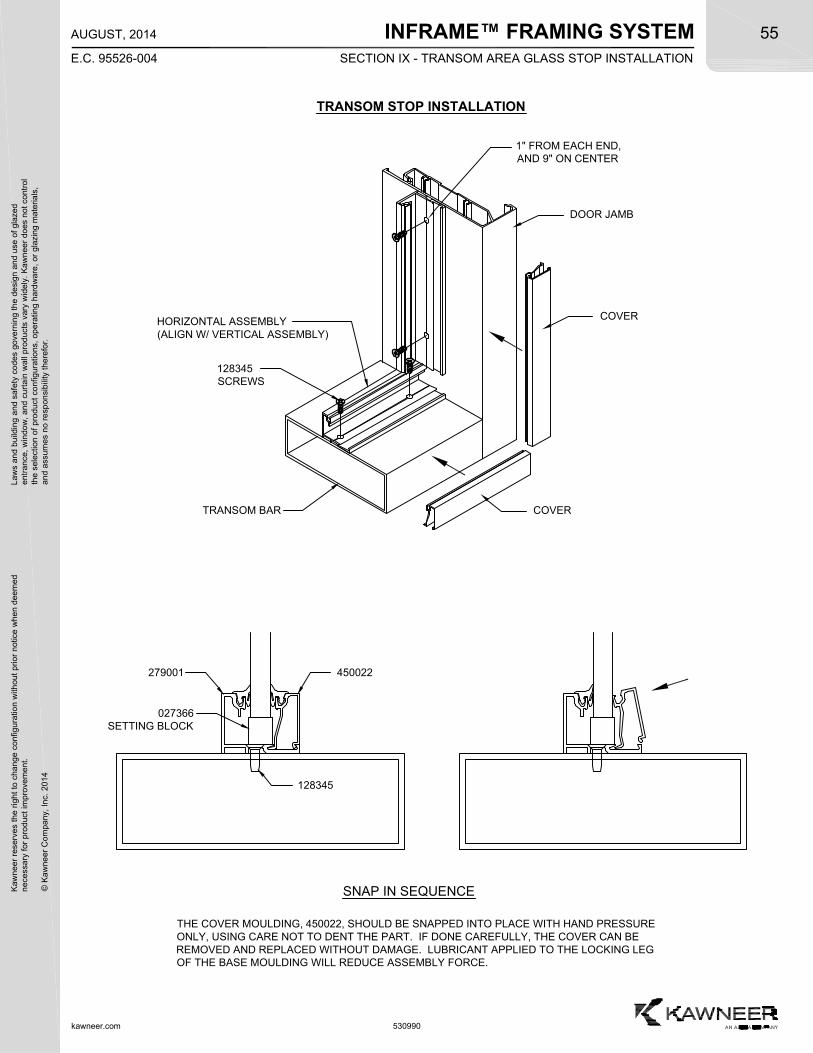
INFRAME™ FRAMING SYSTEMSECTION IX - TRANSOM AREA GLASS STOP INSTALLATION
Kaw
neer
res
erve
s th
e rig
ht
to c
hang
e co
nfig
urat
ion
with
out
prio
r no
tice
whe
n de
emed
nec
essa
ry f
or p
rodu
ct im
pro
vem
ent.
© K
awne
er C
ompa
ny,
Inc.
201
4
Law
s an
d bu
ildin
g a
nd s
afet
y co
des
gove
rnin
g th
e de
sign
and
use
of g
laze
de
ntra
nce,
win
dow
, a
nd c
urta
in w
all p
rod
ucts
var
y w
ide
ly.
Ka
wn
eer
does
not
con
trol
the
sel
ectio
n o
f pr
oduc
t co
nfig
urat
ions
, op
erat
ing
hard
wa
re,
or g
lazi
ng m
ater
ials
,a
nd a
ssum
es n
o re
spon
sibi
lity
ther
efor
.55
kawneer.com
E.C. 95526-004
AUGUST, 2014
530990
TRANSOM BAR
DOOR JAMB
1" FROM EACH END,AND 9" ON CENTER
THE COVER MOULDING, 450022, SHOULD BE SNAPPED INTO PLACE WITH HAND PRESSUREONLY, USING CARE NOT TO DENT THE PART. IF DONE CAREFULLY, THE COVER CAN BEREMOVED AND REPLACED WITHOUT DAMAGE. LUBRICANT APPLIED TO THE LOCKING LEGOF THE BASE MOULDING WILL REDUCE ASSEMBLY FORCE.
279001 450022
SNAP IN SEQUENCE
128345SCREWS
HORIZONTAL ASSEMBLY(ALIGN W/ VERTICAL ASSEMBLY)
COVER
COVER
TRANSOM STOP INSTALLATION
027366SETTING BLOCK
128345
INFRAME™ FRAMING SYSTEM
kawneer.com
56
E.C. 95526-004
AUGUST, 2014
Kaw
neer
res
erve
s th
e rig
ht
to c
hang
e co
nfig
urat
ion
with
out
prio
r no
tice
whe
n de
emed
nec
essa
ry f
or p
rodu
ct im
pro
vem
ent.
© K
awne
er C
ompa
ny,
Inc.
201
4
Law
s an
d bu
ildin
g a
nd s
afet
y co
des
gove
rnin
g th
e de
sign
and
use
of g
laze
de
ntra
nce,
win
dow
, a
nd c
urta
in w
all p
rod
ucts
var
y w
ide
ly.
Ka
wn
eer
does
not
con
trol
the
sel
ectio
n o
f pr
oduc
t co
nfig
urat
ions
, op
erat
ing
hard
wa
re,
or g
lazi
ng m
ater
ials
,a
nd a
ssum
es n
o re
spon
sibi
lity
ther
efor
.
530990
KAWNEER COMPANY, INC.TECHNOLOGY PARK/ATLANTA555 GUTHRIDGE COURTNORCROSS, GEORGIA 30092