Embed Size (px)
Citation preview
Thin-Walled Structures 50 (2012) 56–67
Contents lists available at SciVerse ScienceDirect
Thin-Walled Structures
0263-82
doi:10.1
n Corr
E-m
journal homepage: www.elsevier.com/locate/tws
Influence of roof on dynamic characteristics of dome roof tanks partiallyfilled with liquid
Moslem Amiri n, Saeed Reza Sabbagh-Yazdi
Civil Engineering Department, KN Toosi University of Technology, Tehran, Iran
a r t i c l e i n f o
Article history:
Received 6 May 2011
Received in revised form
20 August 2011
Accepted 22 August 2011Available online 22 October 2011
Keywords:
Finite element model
Liquid storage tank
Partially filled
Roof influence
Natural frequency
Mode shape
Ambient vibration
Fluid–structure interaction
31/$ - see front matter & 2011 Elsevier Ltd. A
016/j.tws.2011.08.010
esponding author.
ail address: [email protected] (M. Am
a b s t r a c t
The influence of roof on the natural frequencies and the modes of fixed roof, ground supported, liquid
storage tanks is presented in this paper. Attention is given to partially filled tanks with the same heights
of 12.19 m and the aspect ratios (H/R) of 2, 1.52, and 1.33. The bottom of tanks is considered to be
anchored to the foundation. The effect of the roof, along with the liquid height, on dynamic properties is
investigated. For this purpose, each tank is modeled in 4 liquid levels, equal to 1.80, 4.80, 8.50, and
10.90 m and in two various roof conditions: with roof (WR) and open top (OT). The finite element
package ANSYS is used to model the tank–liquid systems. Tank roof and wall are meshed by shell
elements and the liquid is modeled using fluid finite elements. The fluid–structure interaction is taken
into account by coupling the nodes at the interface of the fluid and the shell in the radial direction.
Results of ambient vibration tests are used to verify the numerical procedure in which good agreement
is observed between the numerical and the experimental modal parameters. It is found that the
influence of roof on natural frequencies of axial and vertical modes is negligible whereas its effect on
the natural frequencies of circumferential modes is significant. It is also concluded that at low liquid
levels, equal to 1.80 and 4.80 m, the tank roof does affect the axial modes of the tallest and medium
height tanks while, at all of the considered liquid heights and aspect ratios, the tank roof affects the
circumferential mode shapes; this confirms the idea that the roof does restrain the tank top against
radial deformations.
& 2011 Elsevier Ltd. All rights reserved.
1. Introduction
Liquid storage tanks are widely used to store fuel, liquefied gas,water, and other type of liquids. These structures are importantparts of lifeline transmission and distribution systems in which theirserviceability under applied loads is of prime concern. A liquidstorage tank undergoes various types of loads during their servicelife, most of which are dynamic in nature, i.e., earthquake and wind.Since the dynamic response of a structure depends on its dynamiccharacteristics; natural frequencies and mode shapes, to investigatethe dynamic behavior of structure, calculating its dynamic proper-ties is required. In this paper, the effect of the aspect ratio, liquidheight, and roof condition on the natural frequencies and modeshapes of tanks is investigated. It is noticed that tanks have either afixed roof or a floating roof, the present study is limited to fixed rooftanks in which relative displacements or rotations between thecylinder and the roof are not allowed.
Evaluating the dynamic characteristics of liquid storage tanks wasthe subject of many researches. They can be classified into analyticalsolutions and experimental or numerical studies. Tedesco et al. [1],
ll rights reserved.
iri).
Zhang et al. [2], and Askari and Daneshmand [3] used the numericalanalysis along with analytical solution to determine the dynamicproperties of completely full and partially filled tanks. The procedurefor computing the natural frequencies and the modes of partiallyfilled tanks was also developed by Chiba et al. [4], Gupta andHutchinson [5], Han and Liu [6], Gupta [7], and Ventsel et al. [8].Amiri and Sabbagh-Yazdi [9] used the ambient vibration test andfinite element analysis to obtain the dynamic parameters of three tall,anchored, fixed roof, liquid storage tanks. The dynamic properties ofcylindrical tanks were also determined by Mazu�ch et al. [10] andKruntcheva [11] using the theoretical and the experimental methods.The nonlinear vibration response of a water storage tank under largeinput acceleration excitations was studied by Maekawa et al. [12,13].Sweedan and El Damatty [14,15] used laboratory experiments, alongwith analytical and numerical procedures, to extract the naturalfrequencies and the modes of liquid-filled conical tanks.
Moreover, the effect of various parameters on dynamic char-acteristics of storage tanks was also studied by the authors, i.e.,influence of the initial geometric imperfections [16], corrosion ofthe tank wall [17,18], prestressing of the shell materials [19], andthe effect of tank geometry on its fundamental modes [20].
In addition, several equivalent mechanical models have beenproposed to investigate the dynamic properties and behavior ofliquid storage tanks. These models are used in the design codes of
M. Amiri, S.R. Sabbagh-Yazdi / Thin-Walled Structures 50 (2012) 56–67 57
tanks such as Eurocode 8 [21] and API 650 [22]. The first modelproposed for rigid tanks by Housner [23,24], which dates back to1960s. Haroun and Housner [25], Veletsos and Yang [26], andVeletsos [27] independently developed the mechanical modelsthat consider the effect of tank wall flexibility on its dynamicbehavior. Malhotra et al. [28] have further simplified the modelof Veletsos and Yang [26] that makes it more accurate andmore generally applicable; the proposed model is used in Eurocode8 [21].
However, the influence of roof on dynamic properties of liquidstorage tanks has been taken into account by some authors. Amiriand Sabbagh-Yazdi [9] studied the effect of tank roof on dynamiccharacteristics of axial modes of partially filled steel tanks. Virellaet al. [29] used finite element analysis to investigate the influenceof various roof conditions and geometries on the natural periodsof fixed roof empty tanks. It was found that the vibration of emptytanks is represented either by cylinder modes or the roof modessuch that the natural frequencies of the roof modes remainconstant regardless of the aspect ratio of tanks while the naturalfrequencies of the cylinder modes have a linear dependence withthe aspect ratio of tank.
The effect of roof on the natural frequencies and mode shapesof axial, circumferential, and vertical modes of partially filledliquid storage tanks is presented in this paper. The influence of
1.344m
2.438m
2.438m
2.438m
2.438m
2.438m
t = 0.010m
t = 0.010m
t = 0.010m
t = 0.010m
t = 0.010m
1.767
1.198
1.832
1.832
1.832
1.832
1.832
1.832
H =
12.
190m
D = 12.190m
D = 18
2.001m
2.438m
2.438m
2.438m
2.438m
2.438m
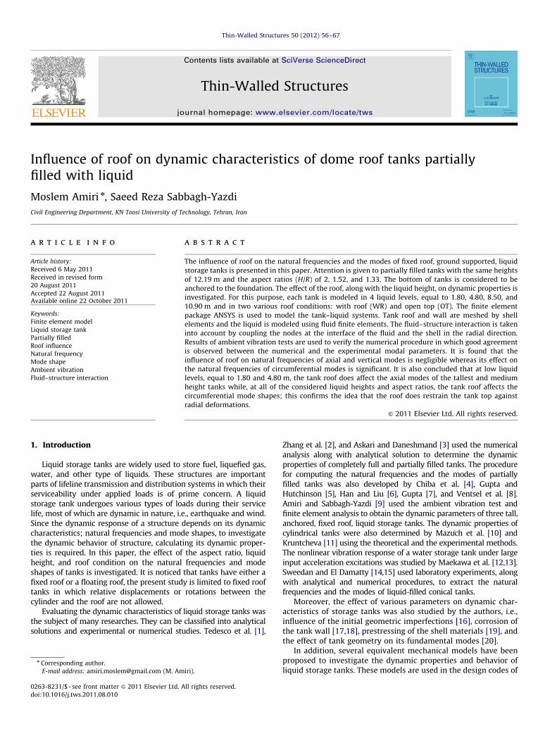
Fig. 1. Geometries of (a) Tank (1),
the aspect ratio and liquid height on vibrational parameters oftanks is also investigated.
2. Numerical models
Three fixed roof, ground supported, liquid storage tanks areconsidered in the present study. However, fixed roof tanks areconstructed by a dome roof or a cone roof, this paper addressesshallow dome roof tanks. The bottom of the tanks is considered tobe anchored to the foundation. The height to radius ratios of tanksare higher than 1.0, which are known as tall tanks. Tanks have thesimilar heights of 12.190 m and different radius of 6.095, 8.00, and9.144 m. The geometry of the considered tanks is shown in Fig. 1.
For the purpose of the computations, the steel of the tank shelland roof has a modulus of elasticity E¼210 GPa, Poisson’s ratio of0.30, and mass density of 7850 kg/m3. The physical properties ofthe liquids stored in tanks are displayed in Table 1.
The general purpose finite element package ANSYS [30] is usedto model the tank–liquid systems. The tank shell and roof aremeshed by Shell181 quadrilateral elements and the fluid regionis meshed by Fluid80 quadrilateral elements. The Shell181 is afour-node quadrilateral shell element with six degrees of freedomper node, which has both stretching and bending capabilities.
m
m
m
m
m
m
m
m
t = 0.00635m
t = 0.00635m
t = 0.00635m
t = 0.008m
t = 0.009m
t = 0.009m
t = 0.010m
t = 0.010m
t = 0.010m
t = 0.010m
t = 0.010m
t = 0.010m
H =
12.
190m
H =
12.
190m
D = 16.00m
.288m
(b) Tank (2), and (c) Tank (3).
M. Amiri, S.R. Sabbagh-Yazdi / Thin-Walled Structures 50 (2012) 56–6758
The Fluid80 is an eight-node fluid element with three degrees offreedom per node, which is used to model contained fluids withoutany net flow rate. The utilized fluid element also includes specialsurface effects, which may be thought of as gravity springs used tohold the surface in place and it can predict the liquid sloshing.
The fluid–structure interaction is taken into account by couplingthe coincident nodes at the interface of the fluid and the shell in theradial direction. Accordingly, the fluid cannot separate from the tankwall in the radial direction but it can move in the tangentialdirections and apply only normal pressures to the tank wall.
The dynamic properties of tanks are derived from free vibra-tion analysis performed by the Reduced Method. In this method,all frequencies and mode shapes are determined within a
Table 1Properties of the considered tanks and their contained liquids.
Tank Height (m) Radius (m) Liquid type Liquid
density
(kg/m3)
Bulk modulus
of elasticity (GPa)
Tank (1) 12.190 6.095 Fuel oil 970 1.43
Tank (2) 12.190 8.00 MTBE 800 1.06
Tank (3) 12.190 9.144 Water 1000 2.15
Table 2Natural frequencies of Tank (1) in liquid height of 4.78 m (Hz).
Frequency (Hz) Difference (%)
Present study 17.22 –
Ambient measurement [9] 16.28 5.5
Malhotra model [28] 18.34 �6.5
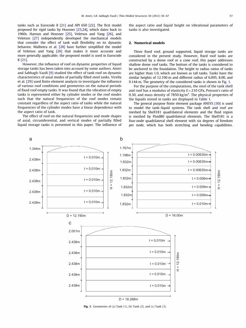
Fig. 2. Vibrational modes of a
Table 3Total number of elements of the finite element model of tanks.
Tank (1) Tank (2)
Shell elements Fluid elements Shell element
Case 1
WR¼1780
OT¼1000
1200
WR¼2772
OT¼1512
Case 2 3000
Case 3 5100
Case 4 6600
specified frequency range. The method uses the reduced numberof degree of freedoms, which are called master degree of free-doms, to formulate the mass and stiffness matrices of the system.The frequency range was set to 1–100 Hz and the first 300 modesof vibration of tanks are extracted in all analyses.
3. Verification of the numerical models
Before using numerical techniques for analyzing the behaviorof tank–liquid systems, they should be validated by experimentalresults. For this purpose, in this paper, the results of the numericalprocedure are compared with the mechanical model proposed byMalhotra et al. [28] and ambient vibration test [9]. A series ofambient tests were carried out on the considered tanks; detaildiscussions about the conducted tests are presented in Ref. [9].However, only results of the test of Tank (1) in liquid height of4.78 m are used to verify the numerical model. The ambientforces, which excite the tanks, are the result of wind currents andmicroseismic waves.
Comparison between results of the numerical model with fieldmeasurements and mechanical model is presented in Table 2. It isobserved that finite element results have good compatibility withexperimental and analytical modal parameters.
4. Type of vibrational modes
A cylindrical tank can vibrate in many different modes:
�
circ
s
The axial modes in which the tank behaves like a verticalcantilever beam.
� The circumferential modes in which the tank shell vibrates inand out and circumferential wave lengths as well as verticalwave length are involved.
ular cylindrical tank.
Tank (3)
Fluid elements Shell elements Fluid elements
2352
WR¼3136
OT¼1600
3072
6468 8448
11,172 13,056
14,112 17,664
M. Amiri, S.R. Sabbagh-Yazdi / Thin-Walled Structures 50 (2012) 56–67 59
�
The vertical modes in which the tank vertically vibrates alongits central axis.The axial and circumferential modes of a cylindrical tank areshown in Fig. 2; these modes can be specified by two integerparameters: m, the number of axial half waves, and n, the numberof circumferential waves [31]. Furthermore, if y is regarded asthe angular coordinate in the circumferential direction, thecircumferential modes can also be classified into two types: thecosðyÞ mode and the cosðnyÞ modes; in the cosðyÞ mode a tankdeflection is found as a single cosine wave while in the cosðnyÞmodes the deformation of the shell contains n circumferentialwaves [29].
5. Influence of roof on dynamic properties of tanks
Since the developed three-dimensional finite element modelshows good agreement with ambient vibration test and mechan-ical model, this can be used to evaluate the influence of roof on
Table 4Ranges of the natural frequencies of free vibration analysis of tanks (Hz).
Tank (1) Tank (2)
fmin (Hz) fmax (Hz) fmin (Hz)
Case 1 12.43 (9.61)a 95.25 (95.25) 9.95 (7.58
Case 2 4.87 (4.01) 99.65 (88.68) 3.96 (3.11
Case 3 2.85 (1.96) 69.67 (69.77) 2.24 (1.52
Case 4 2.54 (1.31) 50.06 (49.17) 1.90 (1.10
a Natural frequency of vibration of OT models.
Table 5Natural frequencies of axial modes of vibration of tanks (Hz).
Roof condition Axial mode number (m)
1 2
Case 1 Tank (1) WR 32.04 (�0.50)a 45.0
OT 32.20 45.0
Tank (2) WR 27.70 (�0.11) 39.3
OT 27.73 39.4
Tank (3) WR 21.96 (�0.14) 32.4
OT 21.99 32.4
Case 2 Tank (1) WR 17.22 (�1.05) 29.9
OT 17.40 30.1
Tank (2) WR 15.27 (�0.52) 26.1
OT 15.35 26.2
Tank (3) WR 12.59 (�0.32) 21.5
OT 12.63 21.6
Case 3 Tank (1) WR 10.91 (�1.10) 21.8
OT 11.03 22.0
Tank (2) WR 9.89 (�1.01) 18.2
OT 9.99 18.3
Tank (3) WR 8.39 (�0.36) 15.3
OT 8.42 15.4
Case 4 Tank (1) WR 8.53 (�1.06) 18.9
OT 8.62 19.0
Tank (2) WR 7.85 (�0.64) 15.2
OT 7.90 15.3
Tank (3) WR 6.89 (�0.58) 13.2
OT 6.93 13.3
a Differences between natural frequencies of WR and OT models¼100(WR�OT/W
dynamic characteristics of tanks. For this purpose, models oftanks are constructed in two various roof conditions: models inwhich the tank roof is completely established, named as with roof(WR) models, and models without modeling the tank roof, namedas open top (OT) models. The OT models are constructed byeliminating the roof from WR models.
In addition, to evaluating the effect of the liquid height ondynamic parameters, each tank is modeled in 4 liquid heights of1.80, 4.80, 8.50, and 10.90 m. These liquid levels are related toapproximately 0.15, 0.40, 0.70, and 0.90 m of the tank height, whichare named as Case 1, Case 2, Case 3, and Case 4, for each tank,respectively. In general, 24 tank–liquid systems are modeled.
The total numbers of elements of the finite element mesh of tankmodels are listed in Table 3. Based on this table, about 55 percent ofthe utilized shell elements are used to model the tank wall and theremaining 45 percent are used to model the tank roof. Ranges of thenatural frequencies of free vibration analysis of tanks are presentedin Table 4. According to this table, the maximum and minimumnatural frequencies of OT models are less than or equal to WRmodels. This is expected because the numbers of local modes, which
Tank (3)
fmax (Hz) fmin (Hz) fmax (Hz)
) 94.84 (94.84) 9.40 (7.74) 96.45 (96.45)
) 97.72 (97.72) 3.70 (3.15) 99.39 (99.27)
) 41.84 (41.49) 2.21 (1.56) 35.71 (35.32)
) 33.13 (32.95) 1.97 (1.05) 30.92 (30.64)
3 4 5
2 (�0.16) N/A N/A N/A
9 N/A N/A N/A
9 (�0.15) N/A N/A N/A
5 N/A N/A N/A
0 (0) N/A N/A N/A
0 N/A N/A N/A
1 (�0.90) N/A N/A N/A
8 N/A N/A N/A
7 (�0.42) 32.94 (�0.15) N/A N/A
8 32.99 N/A N/A
8 (�0.32) 27.09 (�0.04) N/A N/A
5 27.10 N/A N/A
6 (�0.78) 30.17 (�0.50) 35.53 (�0.20) N/A
3 30.32 35.60 N/A
2 (�0.66) 24.89 (�0.24) 28.73 (�0.10) N/A
4 24.95 28.76 N/A
8 (�0.33) 21.24 (�0.19) 24.67 (�0.12) 27.07 (�0.15)
3 21.28 24.70 27.11
7 (�0.47) 26.17 (�0.46) 32.02 (�0.25) 35.82 (�0.14)
6 26.29 32.10 35.87
7 (�0.39) 20.92 (�0.24) 24.65 (�0.20) 27.26 (�0.11)
3 20.97 24.70 27.29
3 (�0.60) 18.60 (�0.22) 22.17 (�0.09) 24.80 (�0.04)
1 18.64 22.19 24.81
R).
M. Amiri, S.R. Sabbagh-Yazdi / Thin-Walled Structures 50 (2012) 56–6760
appeared in free vibration analysis of OT models, are higher thanthose in WR models. It should be noted that maximum number ofderived modes is limited to 300 modes in all analyses.
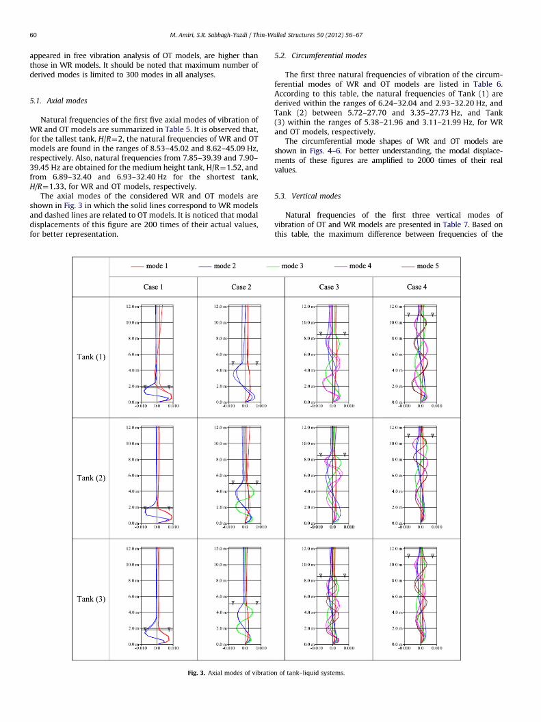
5.1. Axial modes
Natural frequencies of the first five axial modes of vibration ofWR and OT models are summarized in Table 5. It is observed that,for the tallest tank, H/R¼2, the natural frequencies of WR and OTmodels are found in the ranges of 8.53–45.02 and 8.62–45.09 Hz,respectively. Also, natural frequencies from 7.85–39.39 and 7.90–39.45 Hz are obtained for the medium height tank, H/R¼1.52, andfrom 6.89–32.40 and 6.93–32.40 Hz for the shortest tank,H/R¼1.33, for WR and OT models, respectively.
The axial modes of the considered WR and OT models areshown in Fig. 3 in which the solid lines correspond to WR modelsand dashed lines are related to OT models. It is noticed that modaldisplacements of this figure are 200 times of their actual values,for better representation.
Fig. 3. Axial modes of vibratio
5.2. Circumferential modes
The first three natural frequencies of vibration of the circum-ferential modes of WR and OT models are listed in Table 6.According to this table, the natural frequencies of Tank (1) arederived within the ranges of 6.24–32.04 and 2.93–32.20 Hz, andTank (2) between 5.72–27.70 and 3.35–27.73 Hz, and Tank(3) within the ranges of 5.38–21.96 and 3.11–21.99 Hz, for WRand OT models, respectively.
The circumferential mode shapes of WR and OT models areshown in Figs. 4–6. For better understanding, the modal displace-ments of these figures are amplified to 2000 times of their realvalues.
5.3. Vertical modes
Natural frequencies of the first three vertical modes ofvibration of OT and WR models are presented in Table 7. Based onthis table, the maximum difference between frequencies of the
n of tank–liquid systems.
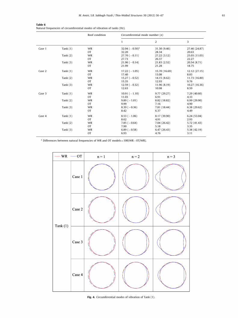
Table 6Natural frequencies of circumferential modes of vibration of tanks (Hz).
Roof condition Circumferential mode number (n)
1 2 3
Case 1 Tank (1) WR 32.04 (�0.50)a 31.30 (9.46) 27.46 (24.87)
OT 32.20 28.34 20.63
Tank (2) WR 27.70 (�0.11) 27.22 (3.12) 25.03 (11.03)
OT 27.73 26.37 22.27
Tank (3) WR 21.96 (�0.14) 21.83 (2.52) 20.54 (8.71)
OT 21.99 21.28 18.75
Case 2 Tank (1) WR 17.22 (�1.05) 15.70 (16.69) 12.12 (27.15)
OT 17.40 13.08 8.83
Tank (2) WR 15.27 (�0.52) 14.15 (8.62) 11.73 (16.80)
OT 15.35 12.93 9.76
Tank (3) WR 12.59 (�0.32) 11.96 (8.19) 10.27 (16.36)
OT 12.63 10.98 8.59
Case 3 Tank (1) WR 10.91 (�1.10) 9.77 (29.27) 7.29 (40.60)
OT 11.03 6.91 4.33
Tank (2) WR 9.89 (�1.01) 8.82 (18.82) 6.99 (29.90)
OT 9.99 7.16 4.90
Tank (3) WR 8.39 (�0.36) 7.81 (18.44) 6.38 (29.62)
OT 8.42 6.37 4.49
Case 4 Tank (1) WR 8.53 (�1.06) 8.17 (39.90) 6.24 (53.04)
OT 8.62 4.91 2.93
Tank (2) WR 7.85 (�0.64) 7.04 (26.42) 5.72 (41.43)
OT 7.90 5.18 3.35
Tank (3) WR 6.89 (�0.58) 6.47 (26.43) 5.38 (42.19)
OT 6.93 4.76 3.11
a Differences between natural frequencies of WR and OT models¼100(WR�OT/WR).
Fig. 4. Circumferential modes of vibration of Tank (1).
M. Amiri, S.R. Sabbagh-Yazdi / Thin-Walled Structures 50 (2012) 56–67 61
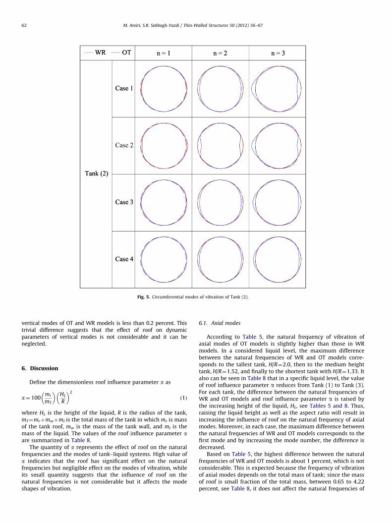
Fig. 5. Circumferential modes of vibration of Tank (2).
M. Amiri, S.R. Sabbagh-Yazdi / Thin-Walled Structures 50 (2012) 56–6762
vertical modes of OT and WR models is less than 0.2 percent. Thistrivial difference suggests that the effect of roof on dynamicparameters of vertical modes is not considerable and it can beneglected.
6. Discussion
Define the dimensionless roof influence parameter a as
a¼ 100mr
mT
� �HL
R
� �2
ð1Þ
where HL is the height of the liquid, R is the radius of the tank,mT¼mrþmwþml is the total mass of the tank in which mr is massof the tank roof, mw is the mass of the tank wall, and ml is themass of the liquid. The values of the roof influence parameter aare summarized in Table 8.
The quantity of a represents the effect of roof on the naturalfrequencies and the modes of tank–liquid systems. High value ofa indicates that the roof has significant effect on the naturalfrequencies but negligible effect on the modes of vibration, whileits small quantity suggests that the influence of roof on thenatural frequencies is not considerable but it affects the modeshapes of vibration.
6.1. Axial modes
According to Table 5, the natural frequency of vibration ofaxial modes of OT models is slightly higher than those in WRmodels. In a considered liquid level, the maximum differencebetween the natural frequencies of WR and OT models corre-sponds to the tallest tank, H/R¼2.0, then to the medium heighttank, H/R¼1.52, and finally to the shortest tank with H/R¼1.33. Italso can be seen in Table 8 that in a specific liquid level, the valueof roof influence parameter a reduces from Tank (1) to Tank (3).For each tank, the difference between the natural frequencies ofWR and OT models and roof influence parameter a is raised bythe increasing height of the liquid, HL, see Tables 5 and 8. Thus,raising the liquid height as well as the aspect ratio will result inincreasing the influence of roof on the natural frequency of axialmodes. Moreover, in each case, the maximum difference betweenthe natural frequencies of WR and OT models corresponds to thefirst mode and by increasing the mode number, the difference isdecreased.
Based on Table 5, the highest difference between the naturalfrequencies of WR and OT models is about 1 percent, which is notconsiderable. This is expected because the frequency of vibrationof axial modes depends on the total mass of tank; since the massof roof is small fraction of the total mass, between 0.65 to 4.22percent, see Table 8, it does not affect the natural frequencies of
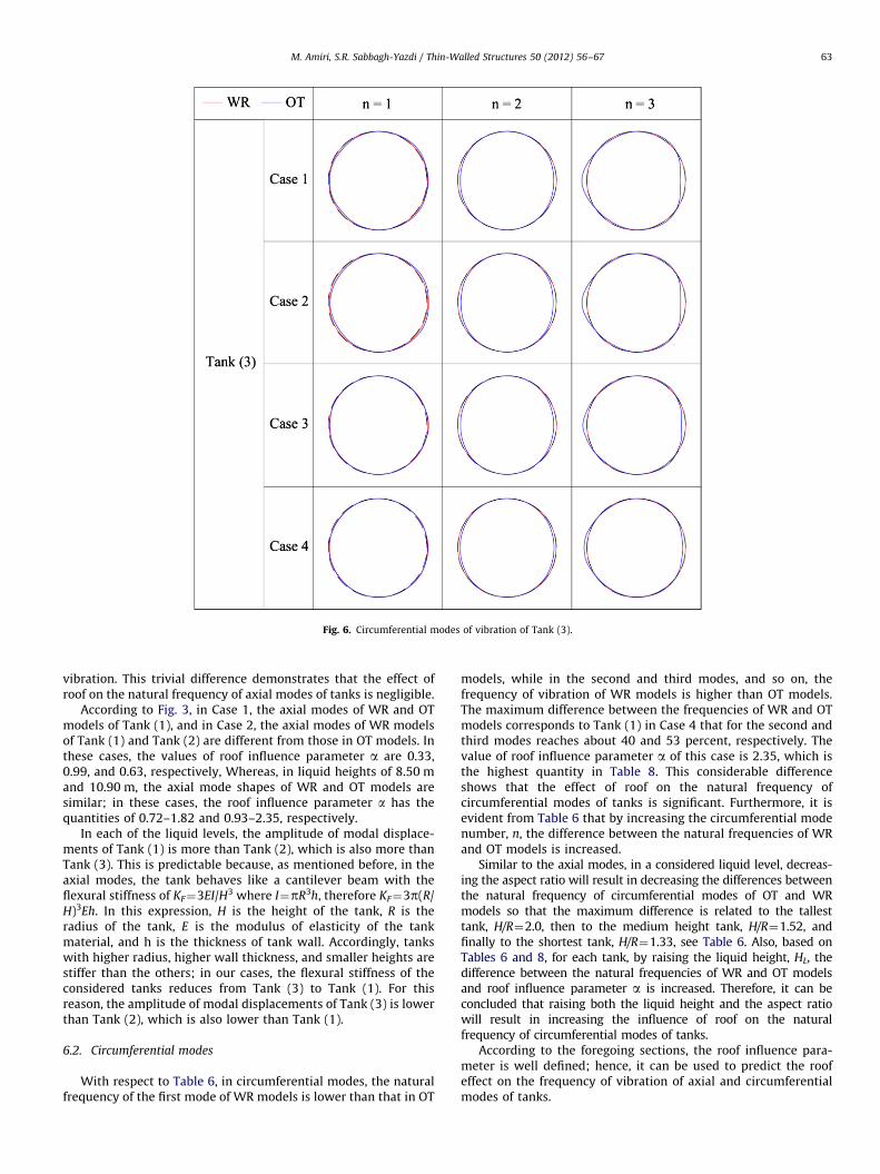
Fig. 6. Circumferential modes of vibration of Tank (3).
M. Amiri, S.R. Sabbagh-Yazdi / Thin-Walled Structures 50 (2012) 56–67 63
vibration. This trivial difference demonstrates that the effect ofroof on the natural frequency of axial modes of tanks is negligible.
According to Fig. 3, in Case 1, the axial modes of WR and OTmodels of Tank (1), and in Case 2, the axial modes of WR modelsof Tank (1) and Tank (2) are different from those in OT models. Inthese cases, the values of roof influence parameter a are 0.33,0.99, and 0.63, respectively, Whereas, in liquid heights of 8.50 mand 10.90 m, the axial mode shapes of WR and OT models aresimilar; in these cases, the roof influence parameter a has thequantities of 0.72–1.82 and 0.93–2.35, respectively.
In each of the liquid levels, the amplitude of modal displace-ments of Tank (1) is more than Tank (2), which is also more thanTank (3). This is predictable because, as mentioned before, in theaxial modes, the tank behaves like a cantilever beam with theflexural stiffness of KF¼3EI/H3 where I¼pR3h, therefore KF¼3p(R/H)3Eh. In this expression, H is the height of the tank, R is theradius of the tank, E is the modulus of elasticity of the tankmaterial, and h is the thickness of tank wall. Accordingly, tankswith higher radius, higher wall thickness, and smaller heights arestiffer than the others; in our cases, the flexural stiffness of theconsidered tanks reduces from Tank (3) to Tank (1). For thisreason, the amplitude of modal displacements of Tank (3) is lowerthan Tank (2), which is also lower than Tank (1).
6.2. Circumferential modes
With respect to Table 6, in circumferential modes, the naturalfrequency of the first mode of WR models is lower than that in OT
models, while in the second and third modes, and so on, thefrequency of vibration of WR models is higher than OT models.The maximum difference between the frequencies of WR and OTmodels corresponds to Tank (1) in Case 4 that for the second andthird modes reaches about 40 and 53 percent, respectively. Thevalue of roof influence parameter a of this case is 2.35, which isthe highest quantity in Table 8. This considerable differenceshows that the effect of roof on the natural frequency ofcircumferential modes of tanks is significant. Furthermore, it isevident from Table 6 that by increasing the circumferential modenumber, n, the difference between the natural frequencies of WRand OT models is increased.
Similar to the axial modes, in a considered liquid level, decreas-ing the aspect ratio will result in decreasing the differences betweenthe natural frequency of circumferential modes of OT and WRmodels so that the maximum difference is related to the tallesttank, H/R¼2.0, then to the medium height tank, H/R¼1.52, andfinally to the shortest tank, H/R¼1.33, see Table 6. Also, based onTables 6 and 8, for each tank, by raising the liquid height, HL, thedifference between the natural frequencies of WR and OT modelsand roof influence parameter a is increased. Therefore, it can beconcluded that raising both the liquid height and the aspect ratiowill result in increasing the influence of roof on the naturalfrequency of circumferential modes of tanks.
According to the foregoing sections, the roof influence para-meter is well defined; hence, it can be used to predict the roofeffect on the frequency of vibration of axial and circumferentialmodes of tanks.
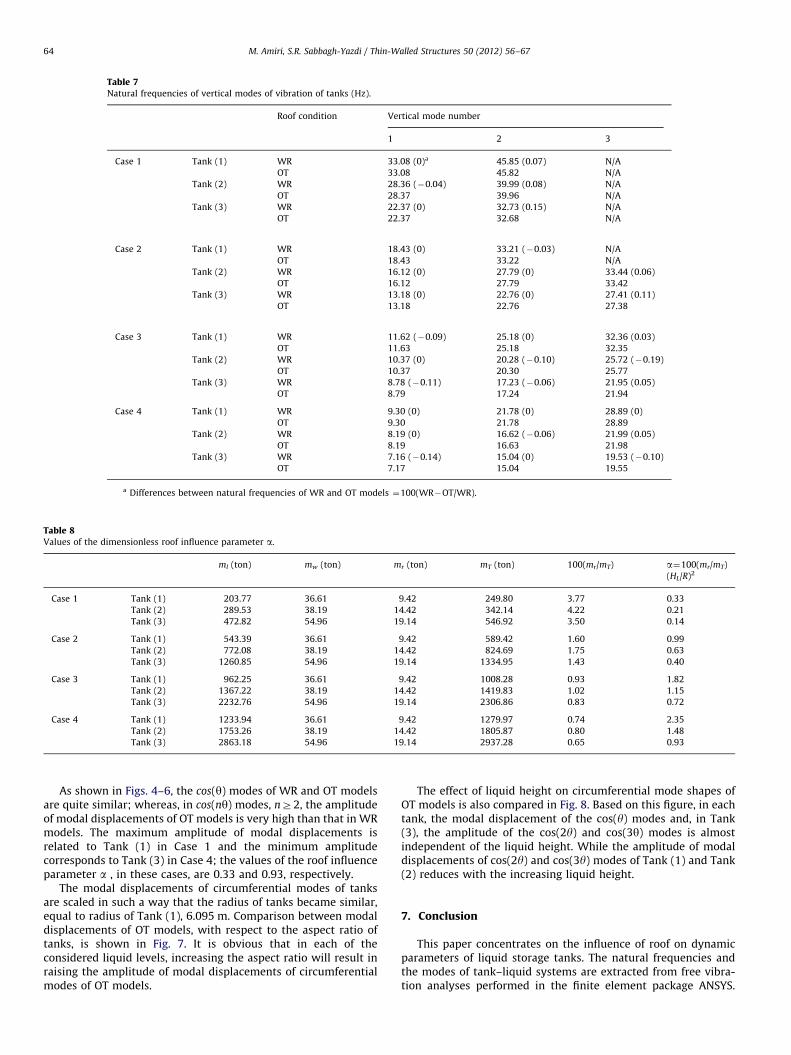
Table 7Natural frequencies of vertical modes of vibration of tanks (Hz).
Roof condition Vertical mode number
1 2 3
Case 1 Tank (1) WR 33.08 (0)a 45.85 (0.07) N/A
OT 33.08 45.82 N/A
Tank (2) WR 28.36 (�0.04) 39.99 (0.08) N/A
OT 28.37 39.96 N/A
Tank (3) WR 22.37 (0) 32.73 (0.15) N/A
OT 22.37 32.68 N/A
Case 2 Tank (1) WR 18.43 (0) 33.21 (�0.03) N/A
OT 18.43 33.22 N/A
Tank (2) WR 16.12 (0) 27.79 (0) 33.44 (0.06)
OT 16.12 27.79 33.42
Tank (3) WR 13.18 (0) 22.76 (0) 27.41 (0.11)
OT 13.18 22.76 27.38
Case 3 Tank (1) WR 11.62 (�0.09) 25.18 (0) 32.36 (0.03)
OT 11.63 25.18 32.35
Tank (2) WR 10.37 (0) 20.28 (�0.10) 25.72 (�0.19)
OT 10.37 20.30 25.77
Tank (3) WR 8.78 (�0.11) 17.23 (�0.06) 21.95 (0.05)
OT 8.79 17.24 21.94
Case 4 Tank (1) WR 9.30 (0) 21.78 (0) 28.89 (0)
OT 9.30 21.78 28.89
Tank (2) WR 8.19 (0) 16.62 (�0.06) 21.99 (0.05)
OT 8.19 16.63 21.98
Tank (3) WR 7.16 (�0.14) 15.04 (0) 19.53 (�0.10)
OT 7.17 15.04 19.55
a Differences between natural frequencies of WR and OT models ¼100(WR�OT/WR).
Table 8Values of the dimensionless roof influence parameter a.
ml (ton) mw (ton) mr (ton) mT (ton) 100(mr/mT) a¼100(mr/mT)
(HL/R)2
Case 1 Tank (1) 203.77 36.61 9.42 249.80 3.77 0.33
Tank (2) 289.53 38.19 14.42 342.14 4.22 0.21
Tank (3) 472.82 54.96 19.14 546.92 3.50 0.14
Case 2 Tank (1) 543.39 36.61 9.42 589.42 1.60 0.99
Tank (2) 772.08 38.19 14.42 824.69 1.75 0.63
Tank (3) 1260.85 54.96 19.14 1334.95 1.43 0.40
Case 3 Tank (1) 962.25 36.61 9.42 1008.28 0.93 1.82
Tank (2) 1367.22 38.19 14.42 1419.83 1.02 1.15
Tank (3) 2232.76 54.96 19.14 2306.86 0.83 0.72
Case 4 Tank (1) 1233.94 36.61 9.42 1279.97 0.74 2.35
Tank (2) 1753.26 38.19 14.42 1805.87 0.80 1.48
Tank (3) 2863.18 54.96 19.14 2937.28 0.65 0.93
M. Amiri, S.R. Sabbagh-Yazdi / Thin-Walled Structures 50 (2012) 56–6764
As shown in Figs. 4–6, the cos(y) modes of WR and OT modelsare quite similar; whereas, in cos(ny) modes, nZ2, the amplitudeof modal displacements of OT models is very high than that in WRmodels. The maximum amplitude of modal displacements isrelated to Tank (1) in Case 1 and the minimum amplitudecorresponds to Tank (3) in Case 4; the values of the roof influenceparameter a , in these cases, are 0.33 and 0.93, respectively.
The modal displacements of circumferential modes of tanksare scaled in such a way that the radius of tanks became similar,equal to radius of Tank (1), 6.095 m. Comparison between modaldisplacements of OT models, with respect to the aspect ratio oftanks, is shown in Fig. 7. It is obvious that in each of theconsidered liquid levels, increasing the aspect ratio will result inraising the amplitude of modal displacements of circumferentialmodes of OT models.
The effect of liquid height on circumferential mode shapes ofOT models is also compared in Fig. 8. Based on this figure, in eachtank, the modal displacement of the cos(y) modes and, in Tank(3), the amplitude of the cos(2y) and cos(3y) modes is almostindependent of the liquid height. While the amplitude of modaldisplacements of cos(2y) and cos(3y) modes of Tank (1) and Tank(2) reduces with the increasing liquid height.
7. Conclusion
This paper concentrates on the influence of roof on dynamicparameters of liquid storage tanks. The natural frequencies andthe modes of tank–liquid systems are extracted from free vibra-tion analyses performed in the finite element package ANSYS.
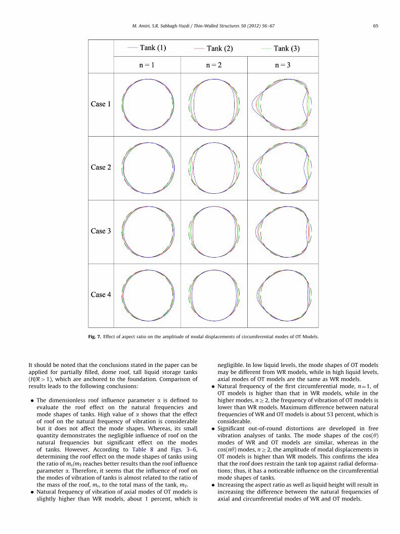
Fig. 7. Effect of aspect ratio on the amplitude of modal displacements of circumferential modes of OT Models.
M. Amiri, S.R. Sabbagh-Yazdi / Thin-Walled Structures 50 (2012) 56–67 65
It should be noted that the conclusions stated in the paper can beapplied for partially filled, dome roof, tall liquid storage tanks(H/R41), which are anchored to the foundation. Comparison ofresults leads to the following conclusions:
�
The dimensionless roof influence parameter a is defined toevaluate the roof effect on the natural frequencies andmode shapes of tanks. High value of a shows that the effectof roof on the natural frequency of vibration is considerablebut it does not affect the mode shapes. Whereas, its smallquantity demonstrates the negligible influence of roof on thenatural frequencies but significant effect on the modesof tanks. However, According to Table 8 and Figs. 3–6,determining the roof effect on the mode shapes of tanks usingthe ratio of mr/mT reaches better results than the roof influenceparameter a. Therefore, it seems that the influence of roof onthe modes of vibration of tanks is almost related to the ratio ofthe mass of the roof, mr, to the total mass of the tank, mT. � Natural frequency of vibration of axial modes of OT models isslightly higher than WR models, about 1 percent, which is
negligible. In low liquid levels, the mode shapes of OT modelsmay be different from WR models, while in high liquid levels,axial modes of OT models are the same as WR models.
� Natural frequency of the first circumferential mode, n¼1, ofOT models is higher than that in WR models, while in thehigher modes, nZ2, the frequency of vibration of OT models islower than WR models. Maximum difference between naturalfrequencies of WR and OT models is about 53 percent, which isconsiderable.
� Significant out-of-round distortions are developed in freevibration analyses of tanks. The mode shapes of the cos(y)modes of WR and OT models are similar, whereas in thecos(ny) modes, nZ2, the amplitude of modal displacements inOT models is higher than WR models. This confirms the ideathat the roof does restrain the tank top against radial deforma-tions; thus, it has a noticeable influence on the circumferentialmode shapes of tanks.
� Increasing the aspect ratio as well as liquid height will result inincreasing the difference between the natural frequencies ofaxial and circumferential modes of WR and OT models.
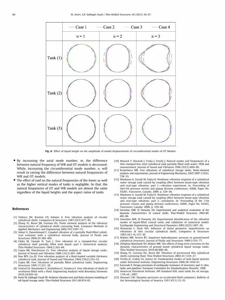
Fig. 8. Effect of liquid height on the amplitude of modal displacements of circumferential modes of OT Models.
M. Amiri, S.R. Sabbagh-Yazdi / Thin-Walled Structures 50 (2012) 56–6766
�
By increasing the axial mode number, m, the differencebetween natural frequency of WR and OT models is decreased.While, increasing the circumferential mode number, n, willresult in raising the difference between natural frequencies ofWR and OT models. � The effect of roof on the natural frequencies of the lower as wellas the higher vertical modes of tanks is negligible. So that, thenatural frequencies of OT and WR models are almost the sameregardless of the liquid heights and the aspect ratios of tanks.
References
[1] Tedesco JW, Kostem CN, Kalnins A. Free vibration analysis of circularcylindrical shells. Computers & Structures 1987;25(5):677–85.
[2] Zhang YL, Reese JM, Gorman DG. Finite element analysis of the vibratorycharacteristics of cylindrical shells conveying fluid. Computer Methods inApplied Mechanics and Engineering 2002;191:5207–31.
[3] Askari E, Daneshmand F. Coupled vibration of a partially fluid-filled cylind-rical container with a cylindrical internal body. Journal of Fluids andStructures 2009;25:389–405.
[4] Chiba M, Yamaki N, Tani J. Free vibration of a clamped-free circularcylindrical shell partially filled with liquid—part I: theoretical analysis.Thin-Walled Structures 1984;2:265–84.
[5] Gupta RK, Hutchinson GL. Free vibration analysis of liquid storage tanks.Journal of Sound and Vibration 1988;122(3):491–506.
[6] Han RPS, Liu JD. Free vibration analysis of a fluid-loaded variable thicknesscylindrical tank. Journal of Sound and Vibration 1994;176(2):235–53.
[7] Gupta RK. Free vibrations of partially filled cylindrical tanks. EngineeringStructures 1995;17:221–30.
[8] Ventsel ES, Naumenko V, Strelnikova E, Yeseleva E. Free vibrations of shells ofrevolution filled with a fluid. Engineering Analysis with Boundary Elements2010;34:856–62.
[9] Amiri M, Sabbagh-Yazdi SR. Ambient vibration test and finite element modeling oftall liquid storage tanks. Thin-Walled Structures 2011;49:974–83.
[10] Mazu�ch T, Hora�cek J, Trnka J, Vesely J. Natural modes and frequencies of athin clamped-free steel cylindrical tank partially filled with water: FEM andmeasurement. Journal of Sound and Vibration 1996;193(3):669–90.
[11] Kruntcheva MR. Free vibrations of cylindrical storage tanks: finite-elementanalysis and experiments. Journal of Engineering Mechanics, ASCE 2007;133(6):728–33.
[12] Maekawa A, Suzuki M, Fujita K. Nonlinear vibration response of a cylindricalwater storage tank caused by coupling effect between beam-type vibrationand oval-type vibration: part 1—vibration experiment. In: Proceeding ofthe11th pressure vessels and piping division conferences, ASME, Paper No.93261, Vancouver, Canada; 2006. p. 329–38.
[13] Maekawa A, Suzuki M, Fujita K. Nonlinear vibration response of a cylindricalwater storage tank caused by coupling effect between beam-type vibrationand oval-type vibration: part 2—simulation. In: Proceeding of the 11thpressure vessels and piping division conferences, ASME, Paper No. 93263,Vancouver, Canada; 2006. p. 339–46.
[14] Sweedan AMI, El Damatty AA. Experimental and analytical evaluation of thedynamic characteristics of conical shells. Thin-Walled Structures 2002;40:465–86.
[15] Sweedan AMI, El Damatty AA. Experimental identification of the vibrationmodes of liquid-filled conical tanks and validation of numerical model.Earthquake Engineering and Structural Dynamics 2003;32(9):1407–30.
[16] Watawala L, Nash WA. Influence of initial geometric imperfections onvibrations of thin circular cylindrical shells. Computers & Structures1983;16(1-4):125–30.
[17] Maheri MR, Severn RT. Impulsive hydrodynamic pressure in ground-basedcylindrical structures. Journal of Fluids and Structures 1989;3:555–77.
[18] Dehghan Manshadi SH, Maheri MR. The effects of long-term corrosion on thedynamic characteristics of ground based cylindrical liquid storage tanks.Thin-Walled Structures 2010;48:888–96.
[19] Zhang YL, Gorman DG, Reese JM. Vibration of prestressed thin cylindricalshells conveying fluid. Thin-Walled Structures 2003;41:1103–27.
[20] Virella JC, Godoy LA, Su�arez LE. Fundamental modes of tank-liquid systemsunder horizontal motions. Engineering Structures 2006;28:1450–61.
[21] Eurocode 8. Design provisions of earthquake resistance of structures, part 4: silos,tanks and pipelines. European Committee for Standardization, Brussels; 1998.
[22] American Petroleum Institute, API Standard 650, steel tanks for oil storage,11th ed.; 2007.
[23] Housner GW. Dynamic pressures on accelerated fluid containers. Bulletin ofthe Seismological Society of America 1957;47(1):15–35.

M. Amiri, S.R. Sabbagh-Yazdi / Thin-Walled Structures 50 (2012) 56–67 67
[24] Housner GW. The dynamic behavior of water tanks. Bulletin of the Seismo-logical Society of America 1963;53(2):381–7.
[25] Haroun MA, Housner GW. Seismic design of liquid storage tanks. Journal ofthe Technical Councils, ASCE 1981;107(TC1):191–207.
[26] Veletsos AS, Yang JY. Earthquake response of liquid storage tanks. In: Proceeding ofthe 2nd engineering mechanics specialty conference, ASCE, Raleigh; 1977. p. 1–24.
[27] Veletsos AS. Seismic response and design of liquid storage tanks. Guidelinesfor the seismic design of oil and gas pipeline systems. New York: TechnicalCouncil on Lifeline Earthquake Engineering, ASCE; 1984. p. 255–370.
[28] Malhotra PK, Wenk T, Wieland M. Simple procedure for seismic analysisof liquid-storage tanks. Structural Engineering International, IABSE 2000;10(3):197–201.
[29] Virella JC, Godoy LA, Su�arez LE. Influence of the roof on the natural periods ofempty steel tanks. Engineering Structures 2003;25:877–87.
[30] ANSYS, User’s manual, revision 5.4, Swanson Analysis System, USA; 1997.[31] Haroun MA. Dynamic analyses of liquid storage tanks. California Institute
of Technology, Earthquake Engineering Research Laboratory, EERL 80-04;1980.


![Untitled-2 [atecotank.com]atecotank.com/images/catalogs/ALUMINUM GEODESIC DOME ROOF.… · ateco tank technologies engineering service co. ltd. geodesic dome ateco dome-roof-seal](https://img.pdfslide.us/doc/110x75/5a822e777f8b9a24668d8ff1/untitled-2-geodesic-dome-roofateco-tank-technologies-engineering-service.jpg)

![Untitled-2 [weboffice.atecotank.com]weboffice.atecotank.com/.../2018/08/ALUMINUM-GEODESIC-DOME-ROOF-2.pdf · The ATECO Aluminium Geodesic Dome features a clear-span, all-aluminum,](https://img.pdfslide.us/doc/110x75/5cfc5efd88c993de0d8bb8b8/untitled-2-the-ateco-aluminium-geodesic-dome-features-a-clear-span-all-aluminum.jpg)