Embed Size (px)
Citation preview
ATECO TANK TECHNOLOGIES ENGINEERING SERVICE CO.
ALUMINIUM GEODESIC DOME ROOF
DESIGN PHASES
FRAME MODELLING ( GEOMETRICAL MODELLING )
STRUCTURAL ANALYSIS ( FRAME LOADING AND DATAINPUT )
DESIGN CHECK ( RESULTS AND EVALUATION )
REPORTING ( PRINTOUT )
3D MODELLING ( THREE DIMENSIONAL REALISTIC MODELLING )
ASSEMBLY AND SHOP DRAWING
Support Modules
WIND AND SNOW CALCULATION
SEISMIC LOAD CALCULATION
CROSS-SECTION OPRIMISATION
TANK SHELL BUCKLING CALCULATION
JAN. 2014
ATECO TANK – ENGINEERING DEPARTMENT
www.atecotank.com
ATECO TANK GEODESIC DOME ROOF DESIGN PHASES
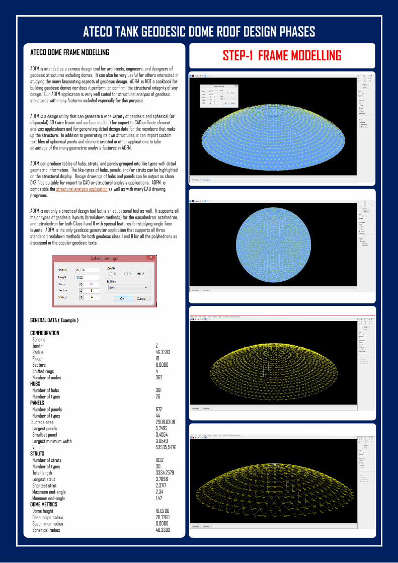
ATECO DOME FRAME MODELLING
ADFM is intended as a serious design tool for architects, engineers, and designers of geodesic structures including domes. It can also be very useful for others interested in studying the many fascinating aspects of geodesic design. ADFM is NOT a cookbook for building geodesic domes nor does it perform, or confirm, the structural integrity of any design. Our ADFM application is very well suited for structural analysis of geodesic structures with many features included especially for this purpose.
ADFM is a design utility that can generate a wide variety of geodesic and spherical (or ellipsoidal) 3D (wire frame and surface models) for import to CAD or finite element analysis applications and for generating detail design data for the members that make up the structure. In addition to generating its own structures, it can import custom text files of spherical points and element created in other applications to take advantage of the many geometric analysis features in ADFM.
ADFM can produce tables of hubs, struts, and panels grouped into like types with detail geometric information. The like-types of hubs, panels, and/or struts can be highlighted on the structural display. Design drawings of hubs and panels can be output as clean DXF files suitable for import to CAD or structural analysis applications. ADFM is
compatible the structural analysis application as well as with many CAD drawing programs.
ADFM is not only a practical design tool but is an educational tool as well. It supports all major types of geodesic layouts (breakdown methods) for the icosahedron, octahedron, and tetrahedron for both Class I and II with special features for studying single face layouts. ADFM is the only geodesic generator application that supports all three standard breakdown methods for both geodesic class I and II for all the polyhedrons as discussed in the popular geodesic texts.
GENERAL DATA ( Example )
CONFIGURATION
Spheric Zenith Z Radius 46,3303 Rings 10 Sectors 8,0000 Shifted rings 4 Number of nodes 362 HUBS Number of hubs 361 Number of types 26 PANELS
Number of panels 672 Number of types 44 Surface area 2908,0308 Largest panels 5,7495 Smallest panel 3,4054
Largest minimum width 3,0549 Volume 53535,5476 STRUTS Number of struts 1032 Number of types 30 Total length 3334,7579 Longest strut 3,7898 Shortest strut 2,3717 Maximum end-angle 2,34 Minimum end-angle 1,47 DOME METRICS
Dome height 10,0200 Base major radius 28,7760 Base minor radius 0,0000 Spherical radius 46,3303 Base area 2593,9987
STEP-1 FRAME MODELLING
ATECO TANK GEODESIC DOME ROOF DESIGN PHASES
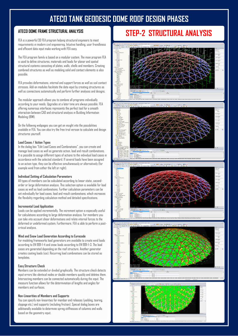
ATECO DOME FRAME STRUCTURAL ANALYSIS
FEA is a powerful 3D FEA program helping structural engineers to meet requirements in modern civil engineering. Intuitive handling, user friendliness
and efficient data input make working with FEA easy.
The FEA program family is based on a modular system. The main program FEA
is used to define structures, materials and loads for planar and spatial structural systems consisting of plates, walls, shells and members. Creating
combined structures as well as modeling solid and contact elements is also
possible.
FEA provides deformations, internal and support forces as well as soil contact stresses. Add-on modules facilitate the data input by creating structures as
well as connections automatically and perform further analyses and designs.
The modular approach allows you to combine all programs individually
according to your needs. Upgrades at a later time are always possible. FEA offering numerous interfaces represents the perfect tool for a smooth
interaction between CAD and structural analysis in Building Information
Modeling (BIM).
On the following webpages you can get an insight into the possibilities available in FEA. You can also try the free trial version to calculate and design
structures yourself.
Load Cases / Action Types
In the dialog box "Edit Load Cases and Combinations", you can create and
manage load cases as well as generate action, load and result combinations. It is possible to assign different types of actions to the individual load cases in
accordance with the selected standard. If several loads have been assigned
to an action type, they can be effective simultaneously or alternatively (for
example wind from either the left or right).
Individual Setting of Calculation Parameters
All types of members can be calculated according to linear static, second-
order or large deformation analysis. This selection option is available for load
cases as well as load combinations. Further calculation parameters can be
set individually for load cases, load and result combinations, which increases the flexibility regarding calculation method and detailed specifications.
Incremental Load Application
Loads can be applied incrementally. The increment option is especially useful
for calculations according to large deformation analysis. For members you can take into account shear deformations and relate internal forces to the
deformed or undeformed system. Furthermore, FEA is able to perform a post-
critical analysis.
Wind and Snow Load Generation According to Eurocode For modeling frameworks load generators are available to create wind loads
according to EN 1991-1-4 and snow loads according to EN 1991-1-3. The load
cases are generated depending on the roof structure. Another generator
creates coating loads (ice). Recurring load combinations can be stored as
templates.
Easy Structure Check
Members can be extended or divided graphically. The structure check detects
input errors like identical nodes or double members quickly and deletes them.
Intersecting members can be connected automatically during the input. The measure function allows for the determination of lengths and angles for
members and surfaces.
Non-Linearities of Members and Supports
You can specify non-linearities for member end releases (yielding, tearing, slippage etc.) and supports (including friction). Special dialog boxes are
additionally available to determine spring stiffnesses of columns and walls
based on the geometry input.
STEP-2 STRUCTURAL ANALYSIS
ATECO TANK GEODESIC DOME ROOF DESIGN PHASES
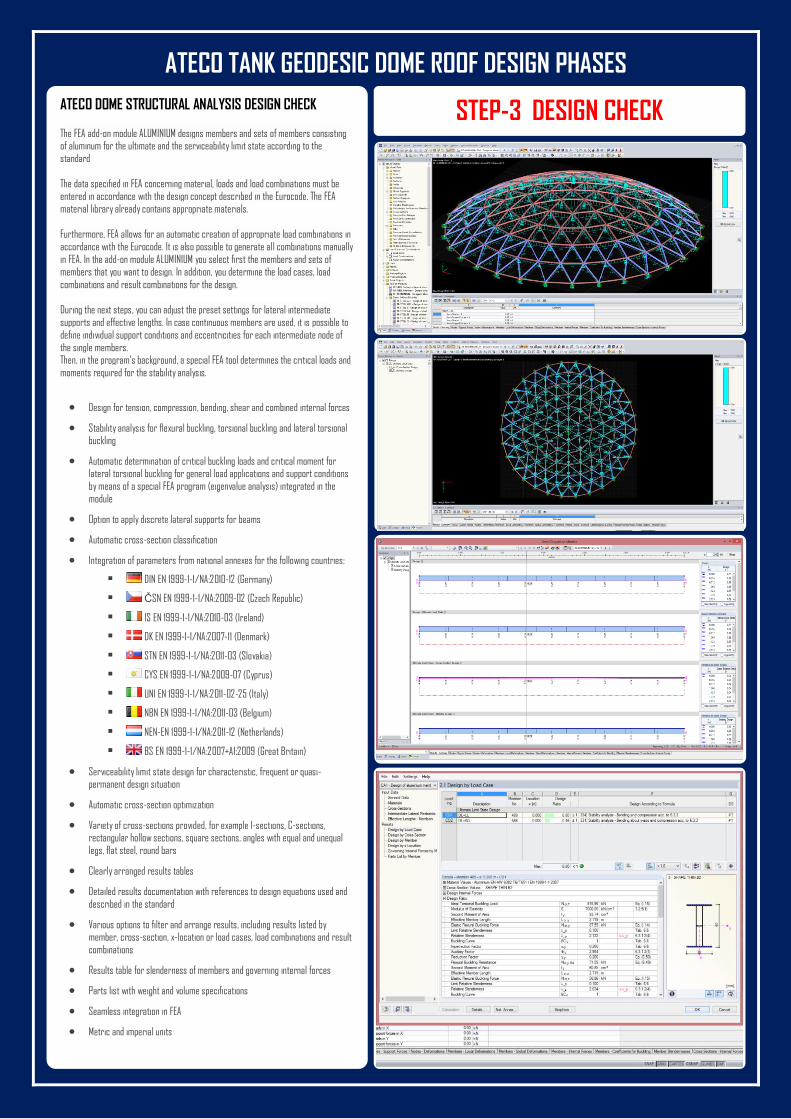
ATECO DOME STRUCTURAL ANALYSIS DESIGN CHECK The FEA add-on module ALUMINIUM designs members and sets of members consisting of aluminum for the ultimate and the serviceability limit state according to the standard The data specified in FEA concerning material, loads and load combinations must be entered in accordance with the design concept described in the Eurocode. The FEA material library already contains appropriate materials. Furthermore, FEA allows for an automatic creation of appropriate load combinations in accordance with the Eurocode. It is also possible to generate all combinations manually in FEA. In the add-on module ALUMINIUM you select first the members and sets of members that you want to design. In addition, you determine the load cases, load combinations and result combinations for the design. During the next steps, you can adjust the preset settings for lateral intermediate supports and effective lengths. In case continuous members are used, it is possible to define individual support conditions and eccentricities for each intermediate node of the single members. Then, in the program's background, a special FEA tool determines the critical loads and
moments required for the stability analysis.
Design for tension, compression, bending, shear and combined internal forces
Stability analysis for flexural buckling, torsional buckling and lateral torsional buckling
Automatic determination of critical buckling loads and critical moment for lateral torsional buckling for general load applications and support conditions by means of a special FEA program (eigenvalue analysis) integrated in the module
Option to apply discrete lateral supports for beams
Automatic cross-section classification
Integration of parameters from national annexes for the following countries:
DIN EN 1999-1-1/NA:2010-12 (Germany)
ČSN EN 1999-1-1/NA:2009-02 (Czech Republic)
IS EN 1999-1-1/NA:2010-03 (Ireland)
DK EN 1999-1-1/NA:2007-11 (Denmark)
STN EN 1999-1-1/NA:2011-03 (Slovakia)
CYS EN 1999-1-1/NA:2009-07 (Cyprus)
UNI EN 1999-1-1/NA:2011-02-25 (Italy)
NBN EN 1999-1-1/NA:2011-03 (Belgium)
NEN-EN 1999-1-1/NA:2011-12 (Netherlands)
BS EN 1999-1-1/NA:2007+A1:2009 (Great Britain)
Serviceability limit state design for characteristic, frequent or quasi-permanent design situation
Automatic cross-section optimization
Variety of cross-sections provided, for example I-sections, C-sections, rectangular hollow sections, square sections, angles with equal and unequal legs, flat steel, round bars
Clearly arranged results tables
Detailed results documentation with references to design equations used and described in the standard
Various options to filter and arrange results, including results listed by member, cross-section, x-location or load cases, load combinations and result combinations
Results table for slenderness of members and governing internal forces
Parts list with weight and volume specifications
Seamless integration in FEA
Metric and imperial units
STEP-3 DESIGN CHECK
ATECO TANK GEODESIC DOME ROOF DESIGN PHASES
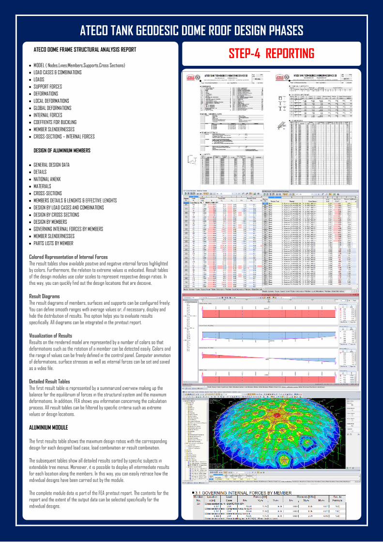
ATECO DOME FRAME STRUCTURAL ANALYSIS REPORT
MODEL ( Nodes,Lines;Members,Supports,Cross Sections)
LOAD CASES & COMBINATIONS
LOADS
SUPPORT FORCES
DEFORMATIONS
LOCAL DEFORMATIONS
GLOBAL DEFORMATIONS
INTERNAL FORCES
COEFFIENTS FOR BUCKLING
MEMBER SLENDERNESSES
CROSS-SECTIONS – INTERNAL FORCES
DESIGN OF ALUMINIUM MEMBERS
GENERAL DESIGN DATA
DETAILS
NATIONAL ANENX
MATERIALS
CROSS-SECTIONS
MEMBERS DETAILS & LENGHTS & EFFECTIVE LENGHTS
DESIGN BY LOAD CASES AND COMBINATIONS
DESIGN BY CROSS SECTIONS
DESIGN BY MEMBERS
GOVERNING INTERNAL FORCES BY MEMBERS
MEMBER SLENDERNESSES
PARTS LISTS BY MEMBER
Colored Representation of Internal Forces
The result tables show available positive and negative internal forces highlighted
by colors. Furthermore, the relation to extreme values is indicated. Result tables
of the design modules use color scales to represent respective design ratios. In
this way, you can quickly find out the design locations that are decisive.
Result Diagrams
The result diagrams of members, surfaces and supports can be configured freely:
You can define smooth ranges with average values or, if necessary, display and
hide the distribution of results. This option helps you to evaluate results
specifically. All diagrams can be integrated in the printout report.
Visualization of Results
Results on the rendered model are represented by a number of colors so that
deformations such as the rotation of a member can be detected easily. Colors and
the range of values can be freely defined in the control panel. Computer animation
of deformations, surface stresses as well as internal forces can be set and saved
as a video file.
Detailed Result Tables
The first result table is represented by a summarized overview making up the
balance for the equilibrium of forces in the structural system and the maximum
deformations. In addition, FEA shows you information concerning the calculation
process. All result tables can be filtered by specific criteria such as extreme
values or design locations.
ALUMINIUM MODULE
The first results table shows the maximum design ratios with the corresponding
design for each designed load case, load combination or result combination.
The subsequent tables show all detailed results sorted by specific subjects in
extendable tree menus. Moreover, it is possible to display all intermediate results
for each location along the members. In this way, you can easily retrace how the
individual designs have been carried out by the module.
The complete module data is part of the FEA printout report. The contents for the
report and the extent of the output data can be selected specifically for the
individual designs.
STEP-4 REPORTING
ATECO TANK GEODESIC DOME ROOF DESIGN PHASES
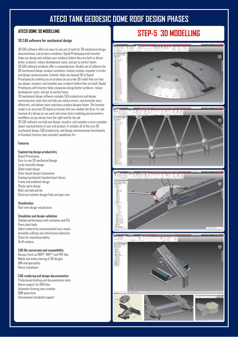
ATECO DOME 3D MODELLING
3D CAD software for mechanical design
3D CAD software offers an easy-to-use set of tools for 3D mechanical design,
documentation, and product simulation. Digital Prototyping with Inventor
helps you design and validate your products before they are built to deliver
better products, reduce development costs, and get to market faster.
3D CAD software products offer a comprehensive, flexible set of software for 3D mechanical design, product simulation, tooling creation, engineer to order,
and design communication. Inventor takes you beyond 3D to Digital
Prototyping by enabling you to produce an accurate 3D model that can help
you design, visualize, and simulate your products before they are built. Digital
Prototyping with Inventor helps companies design better products, reduce
development costs, and get to market faster. 3D mechanical design software includes CAD productivity and design
communication tools that can help you reduce errors, communicate more
effectively, and deliver more innovative product designs faster. The Inventor
model is an accurate 3D digital prototype that can validate the form, fit, and
function of a design as you work and unites direct modeling and parametric workflows so you always have the right tool for the job.
3D CAD software can help you design, visualize, and simulate a more complete
digital representation of your end product. It includes all of the core 3D
mechanical design, CAD productivity, and design communication functionality
of Autodesk Inventor plus extended capabilities for:
Features
Engineering design productivity
Digital Prototyping Easy-to-use 3D mechanical design
Large assembly design
Sheet metal design
Rules-based design/automation
Catalog/purchased/standard part library Frame and weldment design
Plastic parts design
Mold, and tool and die
Electrical systems design/tube and pipe runs
Visualization
Real-time design visualization
Simulation and design validation
Validate performance with simulation and FEA Point cloud tools
Select material by environmental/cost impact
Assembly collision and interference detection
Check for manufacturability
Draft analysis
CAD file conversion and compatibility
Review/mark up DWG™, DWF™, and PDF files
Mobile and online sharing of 3D designs
BIM interoperability
Native translators
CAD rendering and design documentation
Professional drafting and documentation tools
Native support for DWG files
Automatic drawing view creation BOM generation
International standards support
STEP-5 3D MODELLING
ATECO TANK GEODESIC DOME ROOF DESIGN PHASES
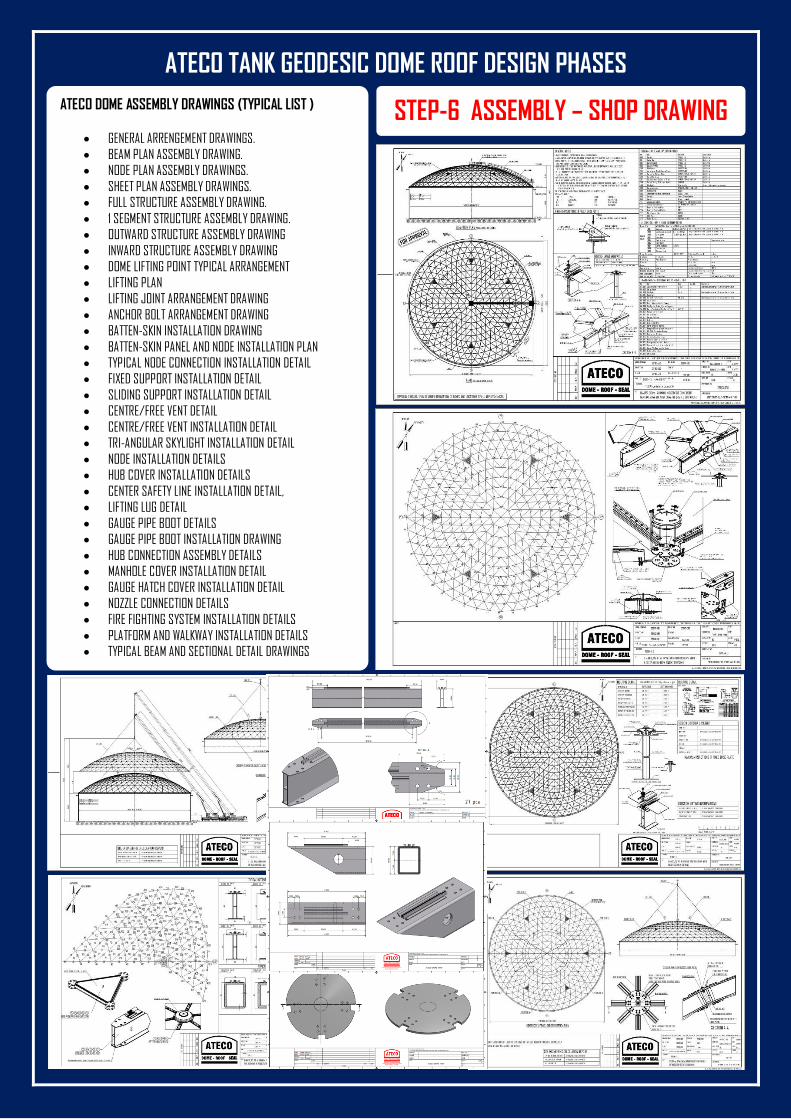
ATECO DOME ASSEMBLY DRAWINGS (TYPICAL LIST )
GENERAL ARRENGEMENT DRAWINGS.
BEAM PLAN ASSEMBLY DRAWING.
NODE PLAN ASSEMBLY DRAWINGS.
SHEET PLAN ASSEMBLY DRAWINGS.
FULL STRUCTURE ASSEMBLY DRAWING.
1 SEGMENT STRUCTURE ASSEMBLY DRAWING.
OUTWARD STRUCTURE ASSEMBLY DRAWING
INWARD STRUCTURE ASSEMBLY DRAWING
DOME LIFTING POINT TYPICAL ARRANGEMENT
LIFTING PLAN
LIFTING JOINT ARRANGEMENT DRAWING
ANCHOR BOLT ARRANGEMENT DRAWING
BATTEN-SKIN INSTALLATION DRAWING
BATTEN-SKIN PANEL AND NODE INSTALLATION PLAN
TYPICAL NODE CONNECTION INSTALLATION DETAIL
FIXED SUPPORT INSTALLATION DETAIL
SLIDING SUPPORT INSTALLATION DETAIL
CENTRE/FREE VENT DETAIL
CENTRE/FREE VENT INSTALLATION DETAIL
TRI-ANGULAR SKYLIGHT INSTALLATION DETAIL
NODE INSTALLATION DETAILS
HUB COVER INSTALLATION DETAILS
CENTER SAFETY LINE INSTALLATION DETAIL,
LIFTING LUG DETAIL
GAUGE PIPE BOOT DETAILS
GAUGE PIPE BOOT INSTALLATION DRAWING
HUB CONNECTION ASSEMBLY DETAILS
MANHOLE COVER INSTALLATION DETAIL
GAUGE HATCH COVER INSTALLATION DETAIL
NOZZLE CONNECTION DETAILS
FIRE FIGHTING SYSTEM INSTALLATION DETAILS
PLATFORM AND WALKWAY INSTALLATION DETAILS
TYPICAL BEAM AND SECTIONAL DETAIL DRAWINGS
STEP-6 ASSEMBLY – SHOP DRAWING
ATECO TANK GEODESIC DOME ROOF DESIGN PHASES
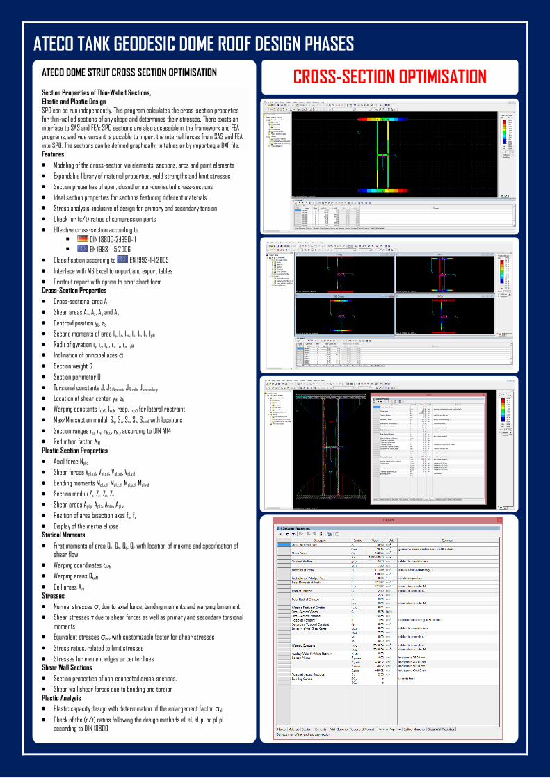
ATECO DOME STRUT CROSS SECTION OPTIMISATION
Section Properties of Thin-Walled Sections, Elastic and Plastic Design
SPO can be run independently. This program calculates the cross-section properties for thin-walled sections of any shape and determines their stresses. There exists an interface to SAS and FEA: SPO sections are also accessible in the framework and FEA programs, and vice versa it is possible to import the internal forces from SAS and FEA into SPO. The sections can be defined graphically, in tables or by importing a DXF file. Features
Modeling of the cross-section via elements, sections, arcs and point elements
Expandable library of material properties, yield strengths and limit stresses
Section properties of open, closed or non-connected cross-sections
Ideal section properties for sections featuring different materials
Stress analysis, inclusive of design for primary and secondary torsion
Check for (c/t) ratios of compression parts
Effective cross-section according to
DIN 18800-2:1990-11
EN 1993-1-5:2006
Classification according to EN 1993-1-1:2005
Interface with MS Excel to import and export tables
Printout report with option to print short form Cross-Section Properties
Cross-sectional area A
Shear areas Ay, Az, Au and Av
Centroid position yS, zS
Second moments of area Iy, Iz, Iyz, Iu, Iv, Ip, IpM
Radii of gyration iy, iz, iyz, iu, iv, ip, ipM
Inclination of principal axes α
Section weight G
Section perimeter U
Torsional constants J, JSt.Venant, JBredt, Jsecondary
Location of shear center yM, zM
Warping constants IωS, IωM resp. IωD for lateral restraint
Max/Min section moduli Sy, Sz, Su, Sv, SωM with locations
Section ranges ru, rv, rM,u, rM,v according to DIN 4114
Reduction factor λM
Plastic Section Properties
Axial force Npl,d
Shear forces Vpl,y,d, Vpl,z,d, Vpl,u,d, Vpl,v,d
Bending moments Mpl,y,d, Mpl,z,d, Mpl,u,d, Mpl,v,d
Section moduli Zy, Zz, Zu, Zv
Shear areas Apl,y, Apl,z, Apl,u, Apl,v
Position of area bisection axes fu, fv
Display of the inertia ellipse Statical Moments
First moments of area Qu, Qv, Qy, Qz with location of maxima and specification of shear flow
Warping coordinates ωM
Warping areas QωM
Cell areas Am Stresses
Normal stresses σx due to axial force, bending moments and warping bimoment
Shear stresses τ due to shear forces as well as primary and secondary torsional
moments
Equivalent stresses σeqv with customizable factor for shear stresses
Stress ratios, related to limit stresses
Stresses for element edges or center lines Shear Wall Sections
Section properties of non-connected cross-sections.
Shear wall shear forces due to bending and torsion Plastic Analysis
Plastic capacity design with determination of the enlargement factor αpl
Check of the (c/t) ratios following the design methods el-el, el-pl or pl-pl according to DIN 18800
CROSS-SECTION OPTIMISATION
ATECO TANK GEODESIC DOME ROOF WIND LOAD CALCULATION
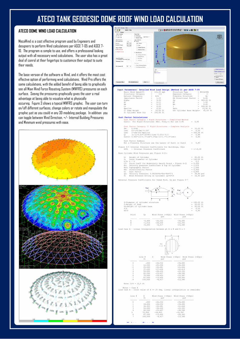
ATECO DOME WIND LOAD CALCULATION
MecaWind is a cost effective program used by Engineers and
designers to perform Wind calculations per ASCE 7-05 and ASCE 7-
10. The program is simple to use, and offers a professional looking
output with all necessary wind calculations. The user also has a great
deal of conrol at their fingertips to customize their output to suite
their needs.
The base version of the software is Wind, and it offers the most cost
effective option of performing wind calculations. Wind Pro offers the
same calculations, with the added benefit of being able to graphically
see all Main Wind Force Resisting System (MWFRS) pressures on each
surface. Seeing the pressures graphically gives the user a real
advantage at being able to visualize what is physically
occuring. Figure 3 shows a typical MWFRS graphic. The user can turn
on/off different surfaces, change colors or rotate and manipulate the
graphic just as you could in any 3D modeling package. In addition you
can toggle between Wind Direction, +/- Internal Building Pressures
and Minimum wind pressures with ease.
Input Parameters: Detailed Wind Load Design (Method 2) per ASCE 7-05
Basic Wind Speed(V) = 122,00 mph Structure Type = BUILDING
Structural Category = III Exposure Category = C
Natural Frequency = N/A Flexible Structure = No
Importance Factor = 1,15 Kd Directional Factor = 0,85
Alpha = 9,50 Zg = 900,00 ft
At = 0,11 Bt = 1,00
Am = 0,15 Bm = 0,65
Cc = 0,20 l = 500,00 ft
Epsilon = 0,20 Zmin = 15,00 ft
f: Dome Height = 20,00 ft hD: Cylinder Base Height= 45,00 ft
D: Cylinder Base Dia = 100,00 ft
Gust Factor Calculations
Gust Factor Category I Rigid Structures - Simplified Method
Gust1: For Rigid Structures (Nat. Freq.>1 Hz) use 0.85 = 0,85
Gust Factor Category II Rigid Structures - Complete Analysis
Zm: 0.6*Ht = 33,00 ft
lzm: Cc*(33/Zm)^0.167 = 0,20
Lzm: l*(Zm/33)^Epsilon = 500,00 ft
Q: (1/(1+0.63*((D+Ht)/Lzm)^0.63))^0.5 = 0,88
Gust2: 0.925*((1+1.7*lzm*3.4*Q)/(1+1.7*3.4*lzm)) = 0,86
Gust Factor Summary
Not a Flexible Structure use the Lessor of Gust1 or Gust2 = 0,85
Figure 6-5 Internal Pressure Coefficients for Buildings, GCpi
GCPi : Internal Pressure Coefficient = +/-0,18
Base Cylinder Wind Pressures per Figure 6-21:
h: Height of Cylinder = 45,00 ft
D: Outer Diameter of Cylinder = 100,00 ft
h/D: h / D = 0,5
Cf: Force Coeff for Moderately Smooth Round - Figure 6-21 = 0,500
Kz: Velocity pressure Coefficient @ Top of Cylinder = 1,070
Kzt: Topographic Factor = 1,000
Kd: Directionality Factor = 0,950
G: Gust Factor = 0,850
qz: Velocity Pressure: 0.00256*Kz*Kzt*Kd*V^2 = 39,84 psf
P: Wind Pressure Acting on Cylinder: qz*G*Cf = 16,93 psf
External Pressure Coefficients for Domed Roof, Cp per Figure 6-7
D-Diameter of cylinder structure = 100,00 ft
f-Height of Dome = 20,00 ft
hD-Height of cylinder base = 45,00 ft
f/D = 0,20
hD/D = 0,45
Point Cp Wind Press (-GCpi) Wind Press (+GCpi)
psf psf
------ ---------- ------------------ ------------------
A -0,906 -24,532 -39,495
B -1,016 -28,430 -43,393
C -0,450 -8,417 -23,380
Load Case A - Linear Interpolation between pt A & B and B & C
Line # X Wind Press (-GCpi) Wind Press (+GCpi)
ft psf psf
------ ---------- ------------------ ------------------
0 ,000 -24,532 -39,495
1 12,500 -25,506 -40,469
2 25,000 -26,481 -41,444
3 37,500 -27,456 -42,419
4 50,000 -28,430 -43,393
5 62,500 -23,427 -38,390
6 75,000 -18,423 -33,387 7 87,500 -13,420 -28,383
8 100,000 -8,417 -23,380
Note: D/8 = 12,5 ft
Notes - Case A
Load Case B - Const value of A <= 25 Deg, linear interpolation on remainder
Line # X Wind Press (-GCpi) Wind Press (+GCpi)
ft psf psf
------ ---------- ------------------ ------------------
0 ,000 -24,532 -39,495
1 18,606 -24,532 -39,495
2 34,303 -26,481 -41,444
3 50,000 -28,430 -43,393
4 62,500 -23,427 -38,390
5 75,000 -18,423 -33,387
6 87,500 -13,420 -28,383
7 100,000 -8,417 -23,380
Notes - Case B
ATECO TANK SHELL BUCKLING ANALYSIS
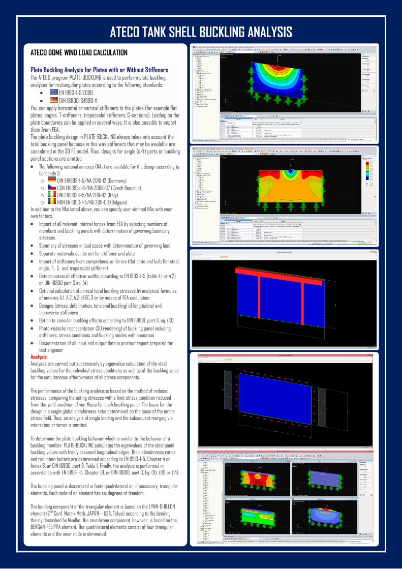
ATECO DOME WIND LOAD CALCULATION
Plate Buckling Analysis for Plates with or Without Stiffeners The ATECO program PLATE-BUCKLING is used to perform plate buckling
analyses for rectangular plates according to the following standards:
EN 1993-1-5:2006
DIN 18800-3:1990-11 You can apply horizontal or vertical stiffeners to the plates (for example flat
plates, angles, T-stiffeners, trapezoidal stiffeners, C-sections). Loading on the
plate boundaries can be applied in several ways. It is also possible to import
them from FEA.
The plate buckling design in PLATE-BUCKLING always takes into account the total buckling panel because in this way stiffeners that may be available are
considered in the 3D FE model. Thus, designs for single (c/t) parts or buckling
panel sections are omitted.
The following national annexes (NAs) are available for the design according to
Eurocode 3:
o DIN EN1993-1-5/NA:2010-12 (Germany)
o CSN EN1993-1-5/NA:2008-07 (Czech Republic)
o UNI EN1993-1-5/NA:2011-02 (Italy)
o NBN EN 1993-1-5/NA:2011-03 (Belgium) In addition to the NAs listed above, you can specify user-defined NAs with your
own factors.
Import of all relevant internal forces from FEA by selecting numbers of
members and buckling panels with determination of governing boundary
stresses
Summary of stresses in load cases with determination of governing load
Separate materials can be set for stiffener and plate
Import of stiffeners from comprehensive library (flat plate and bulb flat steel,
angle, T-, C- and trapezoidal stiffener)
Determination of effective widths according to EN 1993-1-5 (table 4.1 or 4.2) or DIN 18800 part 3 eq. (4)
Optional calculation of critical local buckling stresses by analytical formulas
of annexes A.1, A.2, A.3 of EC 3 or by means of FEA calculation
Designs (stress, deformation, torsional buckling) of longitudinal and
transverse stiffeners
Option to consider buckling effects according to DIN 18800, part 3, eq. (13)
Photo-realistic representation (3D rendering) of buckling panel including
stiffeners, stress conditions and buckling modes with animation
Documentation of all input and output data in printout report prepared for
test engineer
Analysis Analyses are carried out successively by eigenvalue calculation of the ideal
buckling values for the individual stress conditions as well as of the buckling value
for the simultaneous effectiveness of all stress components.
The performance of the buckling analysis is based on the method of reduced
stresses, comparing the acting stresses with a limit stress condition reduced
from the yield condition of von Mises for each buckling panel. The basis for the
design is a single global slenderness ratio determined on the basis of the entire stress field. Thus, an analysis of single loading and the subsequent merging via
interaction criterion is omitted.
To determine the plate buckling behavior which is similar to the behavior of a
buckling member, PLATE-BUCKLING calculates the eigenvalues of the ideal panel
buckling values with freely assumed longitudinal edges. Then, slenderness ratios
and reduction factors are determined according to EN 1993-1-5, Chapter 4 or
Annex B, or DIN 18800, part 3, Table 1. Finally, the analysis is performed in accordance with EN 1993-1-5, Chapter 10, or DIN 18800, part 3, Eq. (9), (10) or (14).
The buckling panel is discretized in finite quadrilateral or, if necessary, triangular
elements. Each node of an element has six degrees of freedom.
The bending component of the triangular element is based on the LYNN-DHILLON
element (2nd Conf. Matrix Meth. JAPAN – USA, Tokyo) according to the bending
theory described by Mindlin. The membrane component, however, is based on the BERGAN-FELIPPA element. The quadrilateral elements consist of four triangular
elements and the inner node is eliminated.

![Untitled-2 [atecotank.com]atecotank.com/images/catalogs/ALUMINUM GEODESIC DOME ROOF.… · ateco tank technologies engineering service co. ltd. geodesic dome ateco dome-roof-seal](https://img.pdfslide.us/doc/110x75/5a822e777f8b9a24668d8ff1/untitled-2-geodesic-dome-roofateco-tank-technologies-engineering-service.jpg)