Embed Size (px)
Citation preview
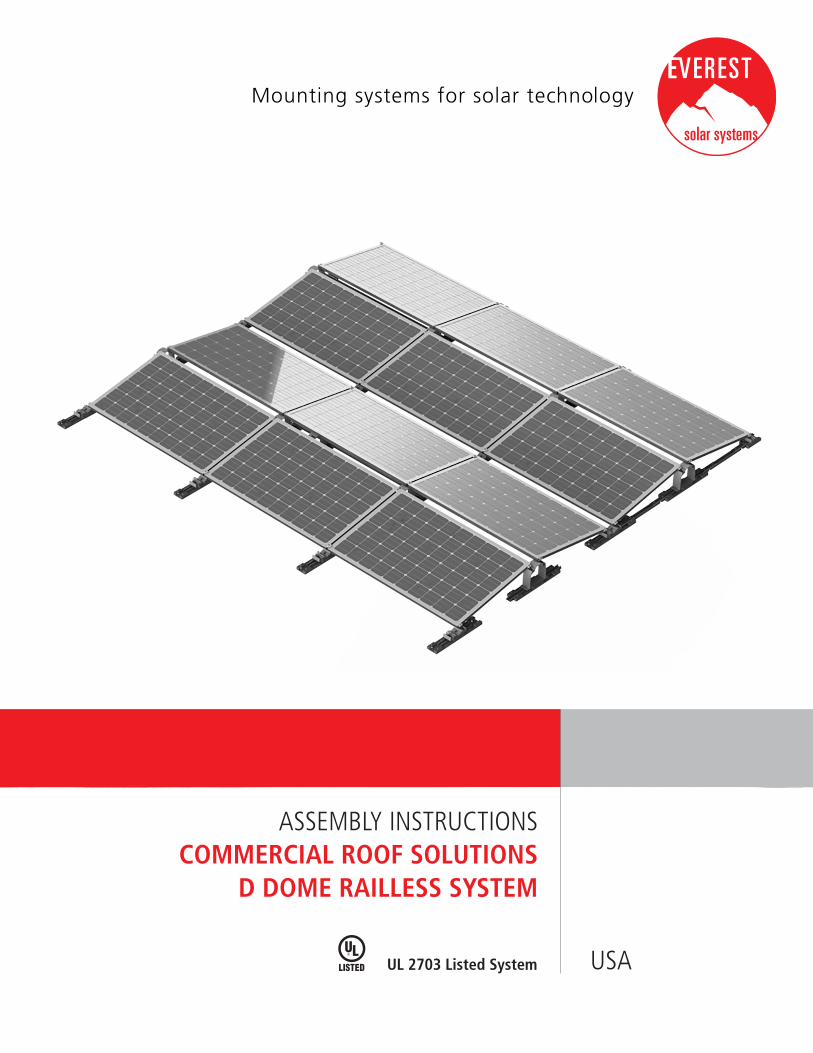
ASSEMBLY INSTRUCTIONSCOMMERCIAL ROOF SOLUTIONS
D DOME RAILLESS SYSTEM
USAUL 2703 Listed System
2
3
4
6
7
8
12
TABLE OF CONTENTS
SAFETY REGULATIONS
MATERIALS REQUIRED
BONDING AND GROUNDING
FIRE RATING
ASSEMBLY
TERMS AND CONDITIONS
TABLE OF CONTENTS
ENGINEERING STRENGTH IS AT OUR CORE
INTRODUCTION TO THE D DOME SYSTEM
With sophisticated product innovations and a deep customer focus, Everest Solar is the engineering leader for all your mounting system needs. We are the US division of K2 Systems, one of Europe’s market leaders with more than 3 GW installed.
We offer proven product solutions and innovative designs. Wind tunnel testing along with advanced structural and electrical validation that should facilitate permitting, design and installation. Our designs result in cost competitive racking systems with dedicated support that will position you to win more projects.
We partner with our customers and suppliers for the long-term. High quality materials and cutting edge designs provide a durable, yet functional system. Our product line is comprised of a few, coordinated components that lower the cost of materials, and simplify installation, saving you time and money. All backed by German engineering, a long track record of quality, and a company that is here to stay.
Thank you for choosing Everest Solar mountings systems for your Solar PV Project.
The D Dome system is an innovative, double-sided, low ballast system designed to be installed in an East/ West orientation.
Our East/ West system eliminates shading between modules and allows higher energy density compared to conventional South-facing systems.
Wind tunnel tested in a boundary layer wind tunnel, the D Dome has one of the lowest ballast requirements of any system available.
2 | 12 Table of Contents
GENERAL SAFETY INSTRUCTIONS
Everest Solar Systems’ General Assembly Instructions must be followed to maintain the exclusive, limited product warranty. Contractor shall verify that it is using the most current instructions by downloading the latest version from our website: http://www.everest-solarsystems.com/us/downloads/technical-information.html or by contacting us directly at [email protected].
In general, the following applies:
¬ Systems should be installed by experienced contractors licensed and qualified to perform the work with professional workmanship and quality.
¬ Before installation, Contractor must verify that the system meets all applicable laws, regulations, ordinances, and codes. Contractor shall verify that the roof or other structures to which the system is being attached are capable of carrying the system loads.
¬ Contractor is solely responsible for work safety and accident prevention regulations and corresponding standards and regulations of the applicable occupational safety and health agency are followed.
¬ Module manufacturer installation guides must be followed. Use approved electrical bonding and grounding components as required by the local or national codes and AHJ.
¬ A copy of these instructions must be on site, and read and understood by all workers during installation.
¬ In the event our general installation and assembly instructions are not followed, or that not all system components and assemblies are used according to these instructions, or that components are used which were not obtained from us, Everest Solar Systems is not liable for any resulting defects and damages, and the exclusive, limited warranty will be void.
¬ The exclusive, limited product warranty shall apply only if all instructions are strictly adhered to and the system is correctly installed. Everest Solar Systems disclaims any and all warranties, express or implied, including without limitation any warranties of merchantability and fitness for a particular purpose other than as set forth in the exclusive, limited warranty in the terms and conditions of sale, which can be viewed under on our website: http://www.everest-solarsystems.com/us/downloads/technical-information.html
¬ The dismantling of the system should be in reverse order of these assembly instructions.
¬ This system can be installed for all standard flat roofs with pressure-resistant substrates and a roof pitch of up to 5 degrees. The elevation angle is 10 degrees.
¬ It is recommended to verify compatibility of the Building Mat with the particular roofing on the project.
¬ Minimum distance to roof edge: 20 in.
¬ A thermal break is required at no more than 50 ft in both directions, North/South and East/West. A minimum separation of 1.5 in is required between separate arrays.
¬ The D Dome is designed to be used with standard 60, 72, and 96 cell modules with a frame height of 1.18-1.97in (30-50mm). All modules used with the D Dome system must be approved by the module manufacturer prior to installation. For a complete list of approved modules, please visit www.everest-solarsystems.com/us/downloads.
3 | 12Safety Regulations
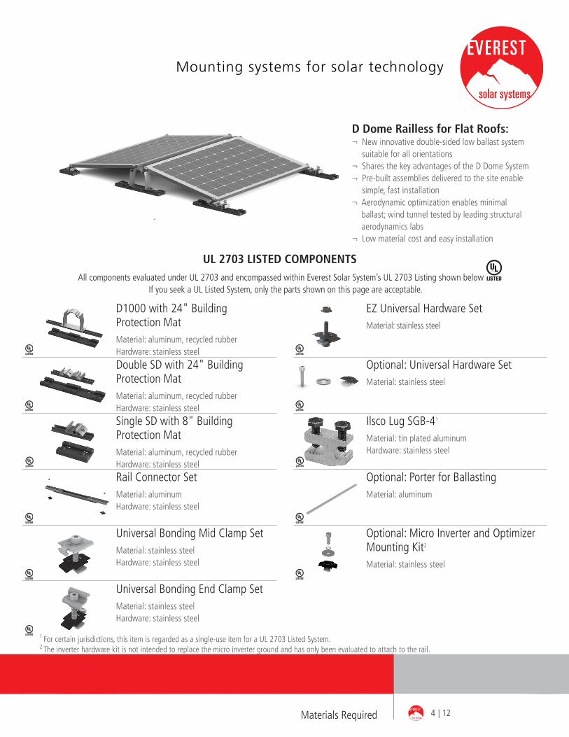
D Dome Railless for Flat Roofs:¬ New innovative double-sided low ballast system
suitable for all orientations¬ Shares the key advantages of the D Dome System¬ Pre-built assemblies delivered to the site enable
simple, fast installation¬ Aerodynamic optimization enables minimal
ballast; wind tunnel tested by leading structural aerodynamics labs
¬ Low material cost and easy installation
All components evaluated under UL 2703 and encompassed within Everest Solar System’s UL 2703 Listing shown below If you seek a UL Listed System, only the parts shown on this page are acceptable.
UL 2703 LISTED COMPONENTS
Double SD with 24" Building Protection MatMaterial: aluminum, recycled rubber Hardware: stainless steel
Single SD with 8" Building Protection MatMaterial: aluminum, recycled rubber Hardware: stainless steel
D1000 with 24" Building Protection MatMaterial: aluminum, recycled rubber Hardware: stainless steel
Universal Bonding End Clamp SetMaterial: stainless steelHardware: stainless steel
Universal Bonding Mid Clamp SetMaterial: stainless steelHardware: stainless steel
Rail Connector Set Material: aluminum Hardware: stainless steel
Optional: Universal Hardware SetMaterial: stainless steel
EZ Universal Hardware SetMaterial: stainless steel
Ilsco Lug SGB-41
Material: tin plated aluminumHardware: stainless steel
Optional: Porter for Ballasting Material: aluminum
Optional: Micro Inverter and Optimizer Mounting Kit2
Material: stainless steel
1 For certain jurisdictions, this item is regarded as a single-use item for a UL 2703 Listed System. 2 The inverter hardware kit is not intended to replace the micro inverter ground and has only been evaluated to attach to the rail.
4 | 12Materials Required
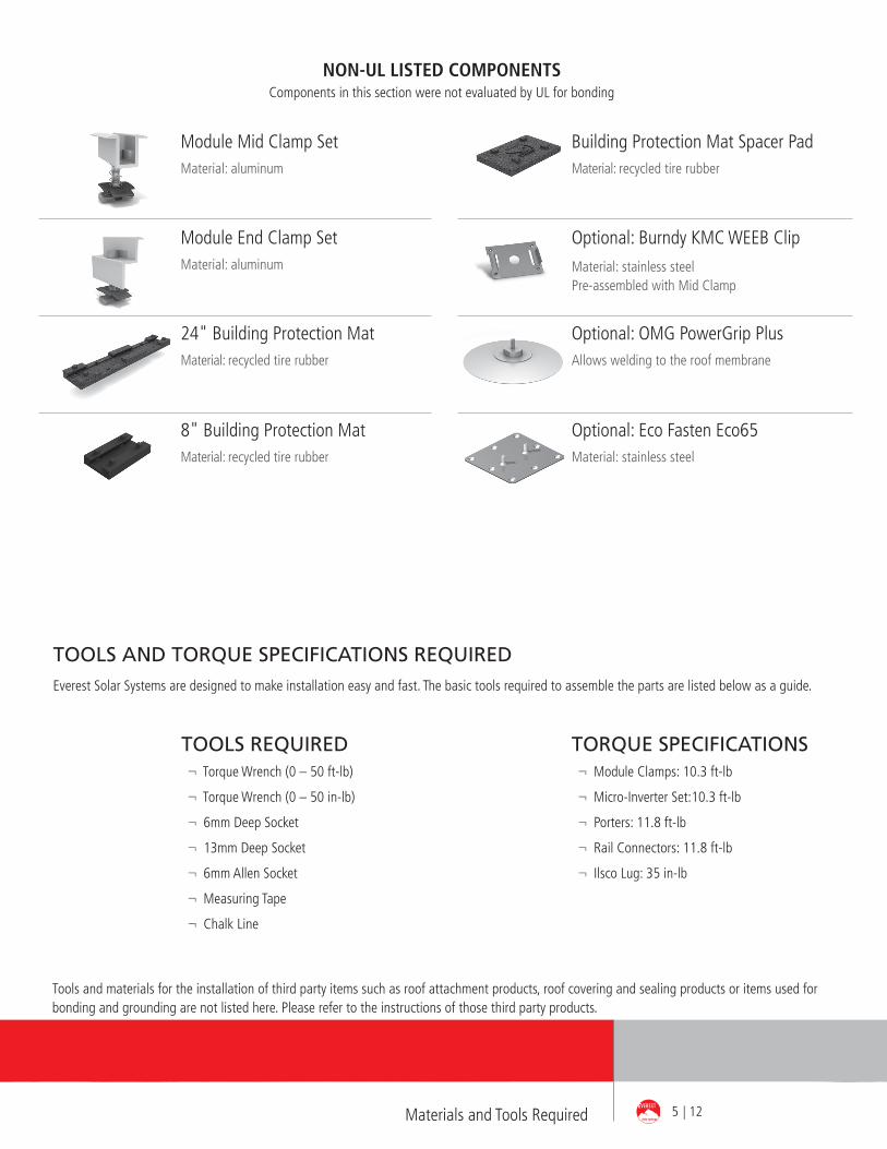
Module End Clamp SetMaterial: aluminum
Module Mid Clamp SetMaterial: aluminum
24" Building Protection MatMaterial: recycled tire rubber
Optional: OMG PowerGrip PlusAllows welding to the roof membrane
Optional: Eco Fasten Eco65Material: stainless steel
Optional: Burndy KMC WEEB Clip
Material: stainless steelPre-assembled with Mid Clamp
Building Protection Mat Spacer PadMaterial: recycled tire rubber
8" Building Protection MatMaterial: recycled tire rubber
5 | 12Materials and Tools Required
TOOLS AND TORQUE SPECIFICATIONS REQUIRED Everest Solar Systems are designed to make installation easy and fast. The basic tools required to assemble the parts are listed below as a guide.
TORQUE SPECIFICATIONS¬ Module Clamps: 10.3 ft-lb
¬ Micro-Inverter Set:10.3 ft-lb
¬ Porters: 11.8 ft-lb
¬ Rail Connectors: 11.8 ft-lb
¬ Ilsco Lug: 35 in-lb
TOOLS REQUIRED¬ Torque Wrench (0 – 50 ft-lb)
¬ Torque Wrench (0 – 50 in-lb)
¬ 6mm Deep Socket
¬ 13mm Deep Socket
¬ 6mm Allen Socket
¬ Measuring Tape
¬ Chalk Line
Tools and materials for the installation of third party items such as roof attachment products, roof covering and sealing products or items used for bonding and grounding are not listed here. Please refer to the instructions of those third party products.
NON-UL LISTED COMPONENTSComponents in this section were not evaluated by UL for bonding
BONDING AND GROUNDING
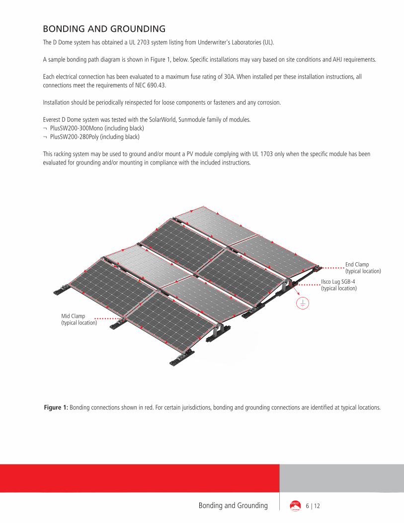
Ilsco Lug SGB-4 (typical location)
End Clamp (typical location)
Mid Clamp (typical location)
The D Dome system has obtained a UL 2703 system listing from Underwriter's Laboratories (UL).
A sample bonding path diagram is shown in Figure 1, below. Specific installations may vary based on site conditions and AHJ requirements.
Each electrical connection has been evaluated to a maximum fuse rating of 30A. When installed per these installation instructions, all connections meet the requirements of NEC 690.43.
Installation should be periodically reinspected for loose components or fasteners and any corrosion.
Everest D Dome system was tested with the SolarWorld, Sunmodule family of modules.¬ PlusSW200-300Mono (including black)¬ PlusSW200-280Poly (including black)
This racking system may be used to ground and/or mount a PV module complying with UL 1703 only when the specific module has been evaluated for grounding and/or mounting in compliance with the included instructions.
Figure 1: Bonding connections shown in red. For certain jurisdictions, bonding and grounding connections are identified at typical locations.
6 | 12Bonding and Grounding
The D Dome system has undergone fire performance testing in accordance with UL 2703, Fire Performance.
A System Class A fire rating is achieved when using D Dome under the following conditions:¬ Used in combination with a UL 1703 Listed module with a fire performance of Type 1 or Type 2. Consult the module manufacturer for
specific fire performance rating information.- Type 1 modules tested with UL- Type 2 modules tested with Western Fire Center
¬ Roof slope of 2/12 inch rise per linear foot or lower. Note: Though fire testing is applicable for roofs up to 2/12 pitch, D Dome is designed for roofs with no greater than 5% slope.
¬ The assembly is to be mounted over a fire resistant roof covering rated for the application.¬ The results of the racking system do not improve a roof covering Class rating.
All documentation can be found on UL‘s Online Database as well as Everest Solar Systems‘ website.
FIRE RATING
7 | 12Fire Rating
Installation of D Dome Railless System
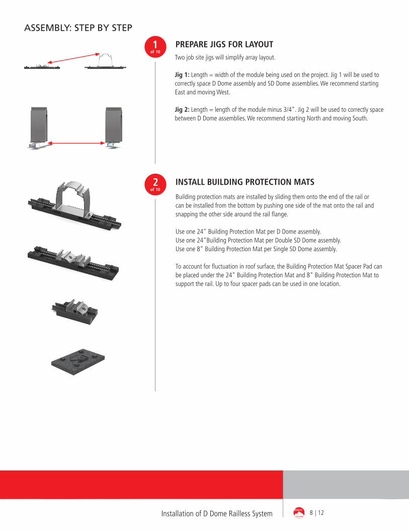
Two job site jigs will simplify array layout.
Jig 1: Length = width of the module being used on the project. Jig 1 will be used to correctly space D Dome assembly and SD Dome assemblies. We recommend starting East and moving West.
Jig 2: Length = length of the module minus 3/4". Jig 2 will be used to correctly space between D Dome assemblies. We recommend starting North and moving South.
ASSEMBLY: STEP BY STEP
1of 10
PREPARE JIGS FOR LAYOUT
2of 10
Building protection mats are installed by sliding them onto the end of the rail or can be installed from the bottom by pushing one side of the mat onto the rail and snapping the other side around the rail flange.
Use one 24" Building Protection Mat per D Dome assembly.Use one 24"Building Protection Mat per Double SD Dome assembly.Use one 8" Building Protection Mat per Single SD Dome assembly.
To account for fluctuation in roof surface, the Building Protection Mat Spacer Pad can be placed under the 24" Building Protection Mat and 8" Building Protection Mat to support the rail. Up to four spacer pads can be used in one location.
INSTALL BUILDING PROTECTION MATS
8 | 12
9 | 12Installation of D Dome Railless System
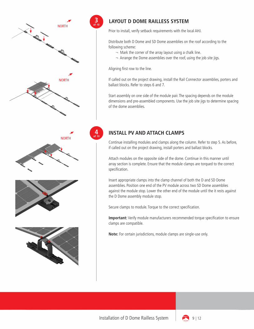
NORTH
Prior to install, verify setback requirements with the local AHJ.
Distribute both D Dome and SD Dome assemblies on the roof according to the following scheme: ¬ Mark the corner of the array layout using a chalk line. ¬ Arrange the Dome assemblies over the roof, using the job site jigs. Aligning first row to the line.
If called out on the project drawing, install the Rail Connector assemblies, porters and ballast blocks. Refer to steps 6 and 7.
Start assembly on one side of the module pair. The spacing depends on the module dimensions and pre-assembled components. Use the job site jigs to determine spacing of the dome assemblies.
LAYOUT D DOME RAILLESS SYSTEM 3of 10
NORTH
NORTH
INSTALL PV AND ATTACH CLAMPS
Continue installing modules and clamps along the column. Refer to step 5. As before, if called out on the project drawing, install porters and ballast blocks.
Attach modules on the opposite side of the dome. Continue in this manner until array section is complete. Ensure that the module clamps are torqued to the correct specification. Insert appropriate clamps into the clamp channel of both the D and SD Dome assemblies. Position one end of the PV module across two SD Dome assemblies against the module stop. Lower the other end of the module until the it rests against the D Dome assembly module stop.
Secure clamps to module. Torque to the correct specification.
Important: Verify module manufacturers recommended torque specification to ensure clamps are compatible.
Note: For certain jurisdictions, module clamps are single-use only.
4of 10
Gap B
Gap A
10 | 12Installation of D Dome Railless System
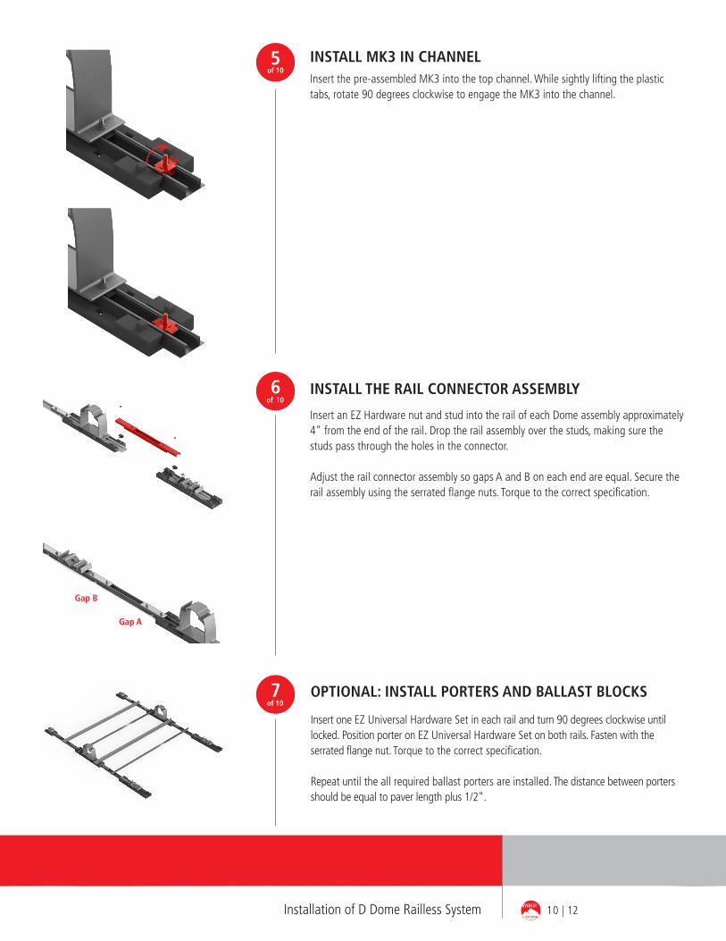
OPTIONAL: INSTALL PORTERS AND BALLAST BLOCKS
Insert one EZ Universal Hardware Set in each rail and turn 90 degrees clockwise until locked. Position porter on EZ Universal Hardware Set on both rails. Fasten with the serrated flange nut. Torque to the correct specification.
Repeat until the all required ballast porters are installed. The distance between porters should be equal to paver length plus 1/2".
7of 10
6of 10
Insert an EZ Hardware nut and stud into the rail of each Dome assembly approximately 4" from the end of the rail. Drop the rail assembly over the studs, making sure the studs pass through the holes in the connector.
Adjust the rail connector assembly so gaps A and B on each end are equal. Secure the rail assembly using the serrated flange nuts. Torque to the correct specification.
INSTALL THE RAIL CONNECTOR ASSEMBLY
5of 10
INSTALL MK3 IN CHANNELInsert the pre-assembled MK3 into the top channel. While sightly lifting the plastic tabs, rotate 90 degrees clockwise to engage the MK3 into the channel.
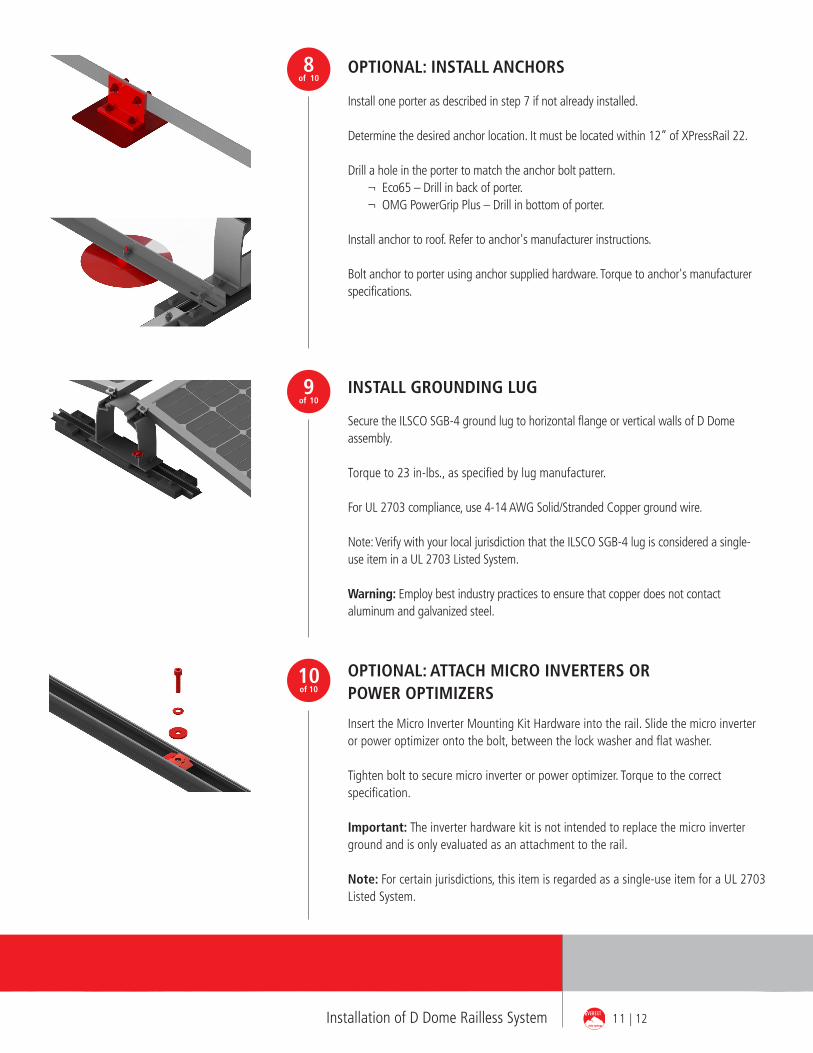
OPTIONAL: ATTACH MICRO INVERTERS OR POWER OPTIMIZERS
Insert the Micro Inverter Mounting Kit Hardware into the rail. Slide the micro inverter or power optimizer onto the bolt, between the lock washer and flat washer.
Tighten bolt to secure micro inverter or power optimizer. Torque to the correct specification.
Important: The inverter hardware kit is not intended to replace the micro inverter ground and is only evaluated as an attachment to the rail.
Note: For certain jurisdictions, this item is regarded as a single-use item for a UL 2703 Listed System.
10of 10
INSTALL GROUNDING LUG
Secure the ILSCO SGB-4 ground lug to horizontal flange or vertical walls of D Dome assembly.
Torque to 23 in-lbs., as specified by lug manufacturer.
For UL 2703 compliance, use 4-14 AWG Solid/Stranded Copper ground wire.
Note: Verify with your local jurisdiction that the ILSCO SGB-4 lug is considered a single-use item in a UL 2703 Listed System.
Warning: Employ best industry practices to ensure that copper does not contact aluminum and galvanized steel.
9of 10
8of 10
OPTIONAL: INSTALL ANCHORS
Install one porter as described in step 7 if not already installed.
Determine the desired anchor location. It must be located within 12” of XPressRail 22.
Drill a hole in the porter to match the anchor bolt pattern. ¬ Eco65 – Drill in back of porter. ¬ OMG PowerGrip Plus – Drill in bottom of porter.
Install anchor to roof. Refer to anchor's manufacturer instructions.
Bolt anchor to porter using anchor supplied hardware. Torque to anchor's manufacturer specifications.
11 | 12Installation of D Dome Railless System
K2 Systems International: World headquarters K2 Systems GmbH, GermanyK2 Systems SARL, FranceK2 Systems SRL, ItalyK2 Solar Mounting Solutions Ltd., UK
Everest Solar Systems, LLC 3809 Ocean Ranch Blvd.Suite 111Oceanside, CA 92056Tel. +1.760.301.5300info@everest-solarsystems.comwww.everest-solarsystems.com
D Dome Railless System Assembly Instructions US6-0616Product images are for illustrative purposes only. Specifications aresubject to change without notice. All sales of our products shall besubject to Everest Solar Systems terms and conditions, includingthe exclusive limited warranty set forth therein.
TERMS AND CONDITIONS
Product images are for illustrative purposes only. Specifications are subject to change without notice. All sales of our products shall be subject to Everest Solar Systems terms and conditions, including the exclusive limited warranty set forth therein. The terms and conditions can be found at http://www.everest-solarsystems.com/us/downloads/technical-information.html
THANK YOU FOR CHOOSING AN EVEREST SOLAR SYSTEMS MOUNTING SYSTEM.Systems from Everest Solar Systems are fast and simple to install. Please contact us if you have any questions or suggestions for improvements. We are looking forward to receive your call on our
Service-Hotline +1 760.301.5300
Ready!


![Untitled-2 [atecotank.com]atecotank.com/images/catalogs/ALUMINUM GEODESIC DOME ROOF.… · ateco tank technologies engineering service co. ltd. geodesic dome ateco dome-roof-seal](https://img.pdfslide.us/doc/110x75/5a822e777f8b9a24668d8ff1/untitled-2-geodesic-dome-roofateco-tank-technologies-engineering-service.jpg)