Embed Size (px)
Citation preview
INDUSTRIALMOTOR CONTROL
Sixth Edition
Stephen L. Herman
Australia • Brazil • Japan • Korea • Mexico • Singapore • Spain • United Kingdom • United States
Industrial Motor Control,6th EditionStephen L. Herman
Vice President, Career and Professional Editorial: Dave Garza
Director of Learning Solutions:Sandy Clark
Managing Editor:Larry Main
Senior Product Manager:John Fisher
Senior Editorial Assistant:Dawn Daugherty
Vice President, Career and Professional Marketing:Jennifer McAvey
Marketing Manager:Deborah S. Yarnell
Marketing Manager:Jimmy Stephens
Marketing Coordinator:Mark Pierro
Production Director:Wendy Troeger
Production Manager:Mark Bernard
Content Project Manager:Christopher Chien
Art Director:David Arsenault
Technology Project Manager:Christopher Catalina
Production Technology Analyst:Thomas Stover
© 2010, 2005, 1999, 1993, 1990, and 1985 Delmar, Cengage Learning
ALL RIGHTS RESERVED. No part of this work covered by the copyright hereinmay be reproduced, transmitted, stored, or used in any form or by any meansgraphic, electronic, or mechanical, including but not limited to photocopying,recording, scanning, digitizing, taping, Web distribution, information networks,or information storage and retrieval systems, except as permitted under Section 107 or 108 of the 1976 United States Copyright Act, without the priorwritten permission of the publisher.
For product information and technology assistance, contact us atProfessional Group Cengage Learning
Customer & Sales Support, 1-800-354-9706For permission to use material from this text or product,submit all requests online at cengage.com/permissions.
Further permissions questions can be e-mailed to [email protected].
Library of Congress Control Number: 2008935164
ISBN-13: 978-1-4354-4239-9ISBN-10: 1-4354-4239-3
Delmar5 Maxwell DriveClifton Park, NY 12065-2919USA
Cengage Learning is a leading provider of customized learning solutions withoffice locations around the globe, including Singapore, the United Kingdom,Australia, Mexico, Brazil and Japan. Locate your local office at:international.cengage.com/region
Cengage Learning products are represented in Canada by Nelson Education, Ltd.
For your lifelong learning solutions, visit delmar.cengage.comVisit our corporate website at cengage.com.
Notice to the Reader
Publisher does not warrant or guarantee any of the products described herein orperform any independent analysis in connection with any of the productinformation contained herein. Publisher does not assume, and expresslydisclaims, any obligation to obtain and include information other than thatprovided to it by the manufacturer. The reader is expressly warned to considerand adopt all safety precautions that might be indicated by the activitiesdescribed herein and to avoid all potential hazards. By following the instructionscontained herein, the reader willingly assumes all risks in connection with suchinstructions. The publisher makes no representations or warranties of any kind,including but not limited to, the warranties of fitness for particular purpose ormerchantability, nor are any such representations implied with respect to thematerial set forth herein, and the publisher takes no responsibility with respectto such material. The publisher shall not be liable for any special, consequential,or exemplary damages resulting, in whole or part, from the readers' use of, orreliance upon, this material.
Printed in Canada1 2 3 4 5 XX 10 09 08
iii
CONTENTSPreface ix
New for the Sixth Edition xContent Highlights xAbout the Author xiAcknowledgments xi
Chapter 1 General Principles of Motor Control 1
Installation of Motors and Control Equipment 1Types of Control Systems 4Functions of Motor Control 7Review Questions 9
Chapter 2 Symbols and Schematic Diagrams 10
Push Buttons 10Switch Symbols 13Basic Schematics 15Sensing Devices 18Selector Switches 22Review Questions 26
Chapter 3 Manual Starters 27
Fractional Horsepower Single-Phase Starters 27Manual Push-Button Starters 30Troubleshooting 33Review Questions 33
Chapter 4 Overload Relays 35
Overloads 35Dual Element Fuses 36Thermal Overload Relays 36Magnetic Overload Relays 43Overload Contacts 47Protecting Large Horsepower Motors 49Review Questions 51
Chapter 5 Relays, Contactors, and Motor Starters 52
Relays 52Electromagnet Construction 53Contactors 61Mechanically Held Contactors and Relays 64Mercury Relays 65Motor Starters 67Review Questions 75
Chapter 6 The Control Transformer 77
Review Questions 83
Chapter 7 Timing Relays 84
Pneumatic Timers 85Clock Timers 86Motor-Driven Timers 87Capacitor Time Limit Relay 87Electronic Timers 88Review Questions 94
Chapter 8 Pressure Switches and Sensors 95
Pressure Switches 95Pressure Sensors 97Review Questions 100
Chapter 9 Float Switches 101
Mercury Bulb Float Switch 102The Bubbler System 103Review Questions 107
Chapter 10 Flow Switches and Sensors 108
Flow Switches 108Flow Sensors 110Review Questions 117
iv Contents
Chapter 11 Limit Switches 118
Micro Limit Switches 119Subminiature Micro Switches 121Limit Switch Application 121Review Questions 123
Chapter 12 Phase Failure Relays 124
Effects of Voltage Variation on Motors 124Review Questions 125
Chapter 13 Solenoid and Motor Operated Valves 126
Solenoid Valves 126Motor Operated Valves 127Review Questions 131
Chapter 14 Temperature Sensing Devices 132
Expansion of Metal 132Resistance Temperature Detectors 137Expansion Due to Pressure 140Smart Temperature Transmitters 141Review Questions 142
Chapter 15 Hall Effect Sensors 143
Principles of Operation 143Hall Generator Applications 144Review Questions 147
Chapter 16 Proximity Detectors 148
Applications 148Circuit Operation 148Mounting 150Capacitive Proximity Detectors 151Ultrasonic Proximity Detectors 151Review Questions 153
Chapter 17 Photodetectors 154
Applications 154Types of Detectors 154Mounting 159Review Questions 161
Chapter 18 Basic Control Circuits 162
Three-Wire Control Circuits 164Review Questions 167
Chapter 19 Schematics and Wiring Diagrams (Circuit #1) 168
Review Questions 171
Chapter 20 Timed Starting for Three Motors (Circuit #2) 172
Review Questions 175
Chapter 21 Float Switch Control of a Pump and Pilot Lights (Circuit #3) 176
Review Questions 178
Chapter 22 Developing a Wiring Diagram (Circuit #1) 179
Review Questions 182
Chapter 23 Developing a Wiring Diagram (Circuit #2) 183
Review Question 184
Chapter 24 Developing a Wiring Diagram (Circuit #3) 187
Review Question 188
Chapter 25 Reading Large Schematic Diagrams 191
Review Questions 197
Chapter 26 Installing Control Systems 198
Review Questions 202
Chapter 27 Hand-Off-Automatic Controls 203
Review Questions 205
Chapter 28 Multiple Push-Button Stations 207
Developing a Wiring Diagram 207Review Questions 211
Chapter 29 Forward-Reverse Control 214
Interlocking 214Developing a Wiring Diagram 215Reversing Single-Phase Split-Phase Motors 216Review Questions 225
Chapter 30 Jogging and Inching 226
Jogging Circuits 226Inching Controls 228Review Questions 232
Chapter 31 Sequence Control 235
Sequence Control Circuit #1 235Sequence Control Circuit #2 235Sequence Control Circuit #3 236
Contents v
Automatic Sequence Control 238Stopping the Motors in Sequence 238Review Questions 246
Chapter 32 DC Motors 249
Application 249Speed Control 249Motor Construction 249Identifying Windings 250Types of DC Motors 251Direction of Rotation 252Standard Connections 254Review Questions 255
Chapter 33 Starting Methods for DC Motors 256
Review Questions 261
Chapter 34 Solid-State DC Drives 262
The Shunt Field Power Supply 263The Armature Power Supply 263Voltage Control 264Field Failure Control 264Current Limit Control 265Speed Control 266Review Questions 268
Chapter 35 Stepping Motors 269
Theory of Operation 269Windings 271Four-Step Switching (Full Stepping) 271Eight-Step Switching (Half Stepping) 272AC Operation 272Motor Characteristics 273Review Questions 276
Chapter 36 The Motor and Starting Methods 277
Review Questions 285
Chapter 37 Resistor and Reactor Starting for AC Motors 286
Resistor Starting 286Reactor Starting 288Step-Starting 288Review Questions 292
Chapter 38 Autotransformer Starting 294
Open and Closed Transition Starting 295Review Questions 299
Chapter 39 Wye-Delta Starting 300
Wye-Delta Starting Requirements 301Dual Voltage Connections 302Connecting the Stator Leads 303Closed Transition Starting 303Overload Setting 305Review Questions 310
Chapter 40 Part Winding Starters 311
Overload Protection 312Dual Voltage Motors 313Motor Applications 313Three-Step Starting 314Automatic Shut-Down 314Review Questions 314
Chapter 41 Consequent Pole Motors 317
Three-Speed Consequent Pole Motors 319Four-Speed Consequent Pole Motors 326Review Questions 331
Chapter 42 Variable Voltage and Magnetic Clutches 332
Voltage Control Methods 333Magnetic Clutches 334Eddy Current Clutches 335Review Questions 336
Chapter 43 Braking 338
Mechanical Brakes 338Dynamic Braking 338Plugging 342Review Questions 350
Chapter 44 Wound Rotor Induction Motors 351
Manual Control of a Wound Rotor Motor 353Timed Controlled Starting 353Wound Rotor Speed Control 355Frequency Control 355Review Questions 358
Chapter 45 Synchronous Motors 360
Starting a Synchronous Motor 360Excitation Current 361The Brushless Exciter 361Direct Current Generator 362Automatic Starting for Synchronous Motors 362
vi Contents
The Field Contactor 362Out-of-Step Relay 362The Polarized Field Frequency Relay 363Power Factor Correction 365Applications 366Review Questions 366
Chapter 46 Variable Frequency Control 367
Alternator Control 368Solid-State Control 368IGBTs 369Inverter Rated Motors 371Variable Frequency Drives Using
SCRs and GTOs 372Review Questions 375
Chapter 47 Motor Installation 377
Determining Motor Current 377Overload Size 384Example Problems 391Review Questions 396
Chapter 48 Developing Control Circuits 397
Developing Control Circuits 397Review Questions 409
Chapter 49 Troubleshooting 410
Safety Precautions 410Voltmeter Basics 411Test Procedure Example 1 414Test Procedure Example 2 416Test Procedure Example 3 419Review Questions 424
Chapter 50 Digital Logic 425
The AND Gate 426The OR Gate 427The INVERTER 427The NOR Gate 428The NAND Gate 429Integrated Circuits 429Testing Integrated Circuits 432Review Questions 432
Chapter 51 The Bounceless Switch 433
Review Questions 436
Chapter 52 Start-Stop Push-Button Control 437
Review Questions 444
Chapter 53 Programmable Logic Controllers 445
Differences Between PLCs and PCs 445Basic Components 446Review Questions 454
Chapter 54 Programming a PLC 455
Circuit Operation 455Developing a Program 457Converting the Program 459Programming in Boolean 461Developing the Program 461Parameters of the Programmable Controller 461Operation of the Circuit 462Entering the Program 465Review Questions 466
Chapter 55 Analog Sensing for Programmable Controllers 467
Installation 469The Differential Amplifier 470Review Questions 470
Chapter 56 Semiconductors 471
Conductors 471Insulators 472Semiconductors 472Review Questions 476
Chapter 57 The PN Junction 477
The PN Junction 477Review Questions 481
Chapter 58 The Zener Diode 482
The Zener Diode 482Review Questions 484
Chapter 59 The Transistor 485
The Transistor 485Review Questions 488
Contents vii
Chapter 60 The Unijunction Transistor 489
The Unijunction Transistor 489Review Questions 491
Chapter 61 The SCR 492
The SCR in a DC Circuit 493The SCR in an AC Circuit 494Phase Shifting the SCR 495Testing the SCR 496Review Questions 496
Chapter 62 The Diac 497
The Diac 497Review Questions 498
Chapter 63 The Triac 499
The Triac Used as an AC Switch 500The Triac Used for AC Voltage Control 500Phase Shifting the Triac 500Testing the Triac 501Review Questions 502
Chapter 64 The 555 Timer 503
Circuit Applications 505Review Questions 509
Chapter 65 The Operational Amplifier 510
Basic Circuits 512Circuit Applications 514Review Questions 520
Appendix 523
Testing Solid-State Components 523Identifying the Leads of a Three-Phase,
Wye-Connected, Dual-Voltage Motor 530Ohm’s Law Formulas 534Standard Wiring Diagram Symbols 535Electronic Symbols 536
Glossary 537
Index 547

This page intentionally left blank
ix
PREFACEThe amount of knowledge an electrician must possessto be able to install and troubleshoot control systems intoday’s industry has increased dramatically in recentyears. A continuous influx of improved control compo-nents allows engineers and electricians to design andinstall even more sophisticated and complex controlsystems. Industrial Motor Control presents the solid-state devices common in an industrial environment.This is intended to help the student understand howmany of the control components operate, such as solid-state relays, rectifiers, SCR drives for direct currentmotors, variable frequency drives for alternating cur-rent motors, and the inputs and outputs of program-mable controllers. Although most electricians do nottroubleshoot circuits on a component level, a basicknowledge of how these electronic devices operate isnecessary in understanding how various control com-ponents perform their functions.
The influx of programmable logic controllers intoindustry has bridged the gap between the responsibili-ties of the electrician and the instrumentation techni-cian. Many industries now insist that electricians andinstrumentation technicians be cross-trained so theycan work more closely together. Industrial Motor Con-trol helps fulfill this requirement. Many of the commoncontrol devices found throughout industry are also dis-cussed from a basic instrumentation standpoint by pro-viding information on analog sensing of pressure, flow,temperature, and liquid level.
The sixth edition of Industrial Motor Control is themost comprehensive revision since the text was firstpublished over twenty years ago. The chapter on motorinstallation has been updated to reflect changes in the2008 National Electrical Code®, and a new unit that in-structs students in basic troubleshooting techniques hasbeen included. The chapters have been rearranged to
present the information in a different order. This re-arrangement was done to reflect recommendationsmade by instructors that use the text.
Industrial Motor Control presents many examplesof control logic and gives the student step-by-step in-structions on how these circuits operate. There are ex-amples of how ladder diagrams can be converted intowiring diagrams. This is the basis for understandinghow to connect control circuits in the field. The conceptof how motor control schematics are numbered is thor-oughly discussed. Students are also given a set of condi-tions that a circuit must meet, and then that circuit is de-veloped in a step-by-step procedure. Learning to designcontrol circuits is a very effective means of learning howcircuit logic works. It is impossible to effectively trou-bleshoot a control circuit if you don’t understand thelogic of what the circuit is intended to do.
Industrial Motor Control is based on the results ofextensive research into content, organization, and effec-tive learning styles. Short chapters help the student tocompletely understand the content before progressingto the next subject, and they permit the instructor tochoose the order of presentation. Each chapter containsextensive illustrations, which have been designed formaximum learning. Color is used to help the student un-derstand exactly what is being conveyed in a particularillustration.
Industrial Motor Control, Sixth Edition, is a com-plete learning package that includes this comprehen-sive textbook, a hands-on Lab Manual, an InteractiveCompanion on CD, an Instructor’s Guide, and an In-structor’s e-resource. The Lab Manual offers practicalhands-on circuits to be wired by the student. Each ofthe labs uses standard components that most electricallabora tories either have on hand or can obtain withoutdifficulty. The Lab Manual lets students learn by doing.
x Prefacex Prefacex Preface
New for the Sixth Edition
• Rearrangement of chapters to reflect the recommen-dations made by instructors that used the text.
• A new chapter on troubleshooting techniques.
• The chapter on motor installation has been updatedin accord with the 2008 National Electrical Code®.
• Many of the chapters have been rewritten in an effortto make the material more understandable for begin-ning students.
• Many of the drawings and illustrations have been up-dated and improved.
The Interactive Companion CD, which can be foundin a sleeve on the inside back cover of this textbook, in-cludes applications and explanations of the concepts de-veloped in the textbook. This exciting CD includes out-standing graphics, animations, and video segments andprovides students with reinforcement of important con-cepts. The text of the licensing agreement for this soft-
ware, along with instructions for installing and operat-ing it, can be found on the pages following the index.
The Instructor’s Guide includes the learning ob-jectives from the textbook for the instructor’s conve-nience, as well as a bank of test questions, and theanswers to all of the test questions and textbook Chap-ter Review Questions.
The new Instructor’s e.resource is an invaluableaddition to the Industrial Motor Control package. Itincludes PowerPoint slides for each unit (a total ofnearly 500), nearly 1,000 Computerized Test Bankquestions, and an image library containing hundreds offull-color images in electronic format.
Content Highlights
• The most commonly used solid-state devices are thor-oughly described, in terms of both operation andtypical application.
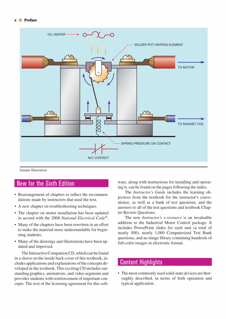
O/L HEATER
SOLDER POT HEATING ELEMENT
SPRING PRESSURE ON CONTACT
N/C CONTACT
TO MOTOR
TO MAGNET COIL
Sample Illustration
Preface xi
• Information on analog devices that sense pressure,flow, and temperature has been added to help bridgethe gap between the industrial electrician and theinstrumentation technician.
• DC and AC motor theory is included so students willunderstand the effects of control circuits on motorcharacteristics.
• The text covers the operating characteristics of step-ping motors when connected to either DC or ACvoltage.
• Detailed instructions are given for connecting motorsin the field, including the size of conductors, over-load relays, and fuses or circuit breakers. All calcula-tions are taken from the National Electrical Code®.
• The principles of digital logic are described in suffi-cient detail for students to understand programmablecontrollers and prepare basic programs.
• A step-by-step testing procedure for electronic com-ponents is provided in the Appendix.
• Starting methods for hermetically sealed single-phasemotors includes the hot-wire relay, solid-state start-ing relay, current relay, and potential relay.
• Extensive coverage on overload relays and methodsof protecting large horsepower motors.
• Extensive coverage of variable frequency drives.
• Extensive coverage of solid-state control devices inaddition to electromagnetic devices.
• Basic electronics is not a prerequisite for studying thistext. Sufficient solid-state theory is presented to en-able the student to understand and apply the conceptsdiscussed.
About the Author
Stephen L. Herman has been both a teacher of industrialelectricity and an industrial electrician for many years.He obtained formal training at Catawba Valley TechnicalCollege in Hickory, North Carolina, and at numerousseminars and manufacturers’ schools. He also attendedStephen F. Austin University in Nacogdoches, Texas,and earned an Associates Degree in Electrical Technol-ogy from Lee College in Baytown, Texas. He was em-ployed as an electrical installation and maintenance instructor at Randolph Technical College in Asheboro,North Carolina, for nine years. Mr. Herman then re-turned to industry for a period of time before becomingthe lead instructor for the Electrical Technology Pro-
gram at Lee College in Baytown, Texas. He retired fromLee College with twenty years of service and presentlylives with his wife in Pittsburg, Texas. Mr. Herman is arecipient of the Excellence in Teaching Award presentedby the Halliburton Education Foundation.
Acknowledgments
The following individuals provided detailed critiquesof the manuscript and offered valuable suggestions forimprovement of the sixth edition of this text:
Salvador ArandaSavannah Technical College5717 White Bluff RoadSavannah, GA 31405-5521
Richard CutbirthElectrical JATC620 Legion WayLas Vegas, NV 89110
Harry KatzSouth Texas Electrical JATC1223 East EuclidSan Antonio, TX 78212
Rick HecklingerToledo Electrical JATC803 Lime City RoadRossford, OH 43460
Ivan NickersonNorth Platte Community College1101 Halligan DriveNorth Platte, NE 69101
Alan BowdenCentral Westmoreland Area Vocational SchoolArona RoadNew Stanton, PA 15672
The following companies provided the photographsused in this text:
Allen-Bradley Company1201 South Second StreetMilwaukee, WI 53204
Automatic Switch Company50-A Hanover RoadFlorham Park, NJ 07932
xii Preface
Eaton CorporationCutler-Hammer Products
4201 North 27th StreetMilwaukee, WI 53216
Eagle Signal ControlsA Division of Gulf & Western Manufacturing Company736 Federal StreetDavenport, IA 52803
Emerson Electric CompanyIndustrial Controls Division3300 South Standard StreetSanta Ana, CA 92702
Furnas Electric Company1007 McKee StreetBatavia, IL 60510
GE Fanuc Automation North America, Inc.P.O. Box 8106Charlottesville, VA 22906
General Electric Company101 Merritt 7, P.O. Box 5900Norwalk, CT 06856
Hevi-Duty ElectricA Division of General Signal CorporationP.O. Box 268, Highway 17 SouthGoldsboro, NC 27530
International RectifierSemiconductor Division233 KansasEl Segundo, CA 90245
McDonnell & Miller, ITT3500 N. Spaulding AvenueChicago, IL 60618
McGraw-Edison CompanyElectric Machinery800 Central AvenueMinneapolis, MN 55413
Micro SwitchA Honeywell Division11 West Spring StreetFreeport, IL 61032
RCASolid State DivisionRoute 202Somerville, NJ 08876
Ramsey Controls, Inc.335 Route 17Mahwah, NJ 07430
Reliance Electric24701 Euclid AvenueCleveland, OH 44117
Sparling Instruments, Co. Inc.4097 North Temple City BoulevardEl Monte, CA 91734
Square D CompanyP.O. Box 472Milwaukee, WI 53201
The Superior Electric CompanyBristol, CT 06010
Struthers-Dunn, Inc.Systems Division4140 Utica Ridge RoadP.O. Box 1327Bettendorf, IA 52722-1327
Tektronix, Inc.P.O. Box 500Beaverton, OR 97077
Telemecanique, Inc.2525 S. Clearbrook DriveArlington Heights, IL 60005
Turck Inc.3000 Campus DrivePlymouth, MN 55441
U.S. Electrical Motors DivisionEmerson Electric Company125 Old Gate LaneMilford, CT 06460
Vactec, Inc.10900 Page BoulevardSt. Louis, MO 63132
Warner Electric Brake & Clutch Company449 Gardner StreetSouth Beloit, IL 61080
The following individuals provided detailed reviewcomments and suggestions for this edition of the text:
Bob KellerDayton Electrical JATCGreen County Career CenterXenia, OH 45385

Preface xiii
Madison BurnettAssistant Training Director/InstructorElectrical JATC of Southern NevadaLas Vegas, Nevada 89110
Richard ParedesTraining InstructorIBEW Local Union 164Jersey City, NJ

This page intentionally left blank
1
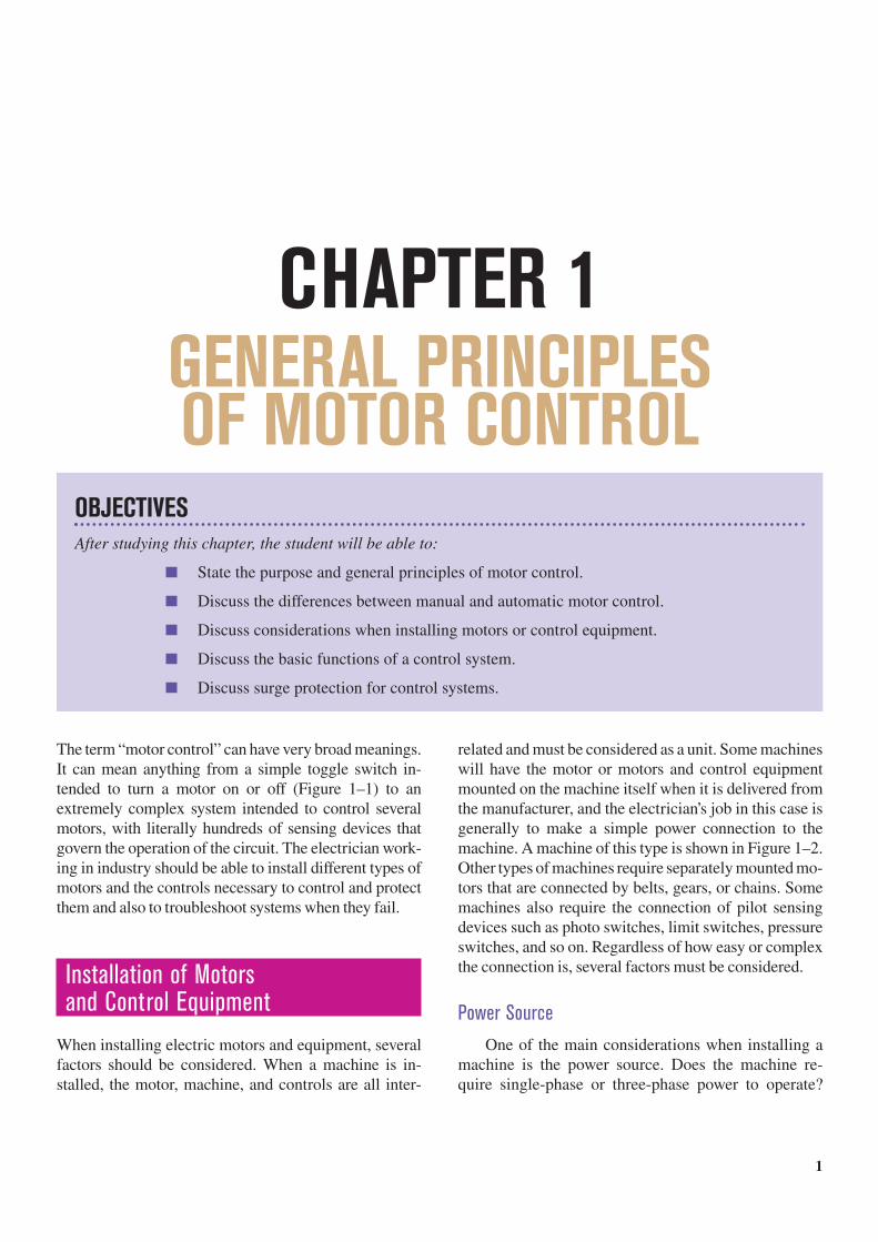
OBJECTIVESAfter studying this chapter, the student will be able to:
State the purpose and general principles of motor control.
Discuss the differences between manual and automatic motor control.
Discuss considerations when installing motors or control equipment.
Discuss the basic functions of a control system.
Discuss surge protection for control systems.
CHAPTER 1GENERAL PRINCIPLES OF MOTOR CONTROL
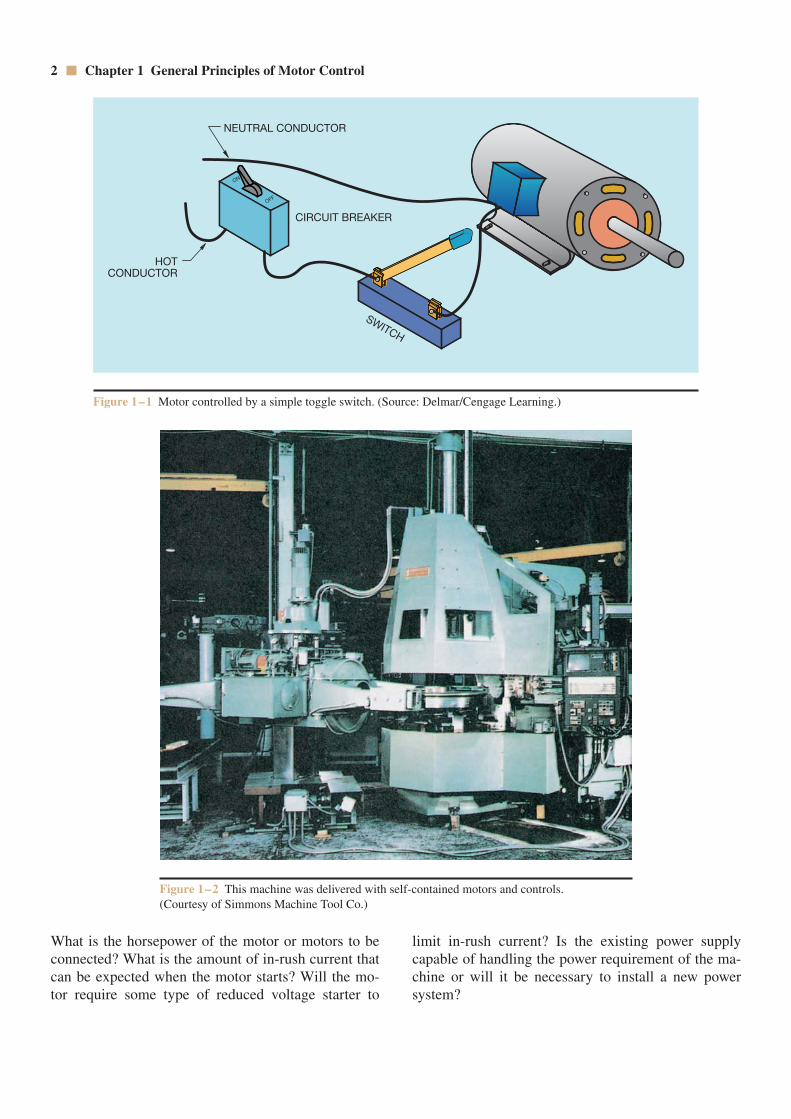
The term “motor control” can have very broad meanings.It can mean anything from a simple toggle switch in-tended to turn a motor on or off (Figure 1–1) to anextremely complex system intended to control severalmotors, with literally hundreds of sensing devices thatgovern the operation of the circuit. The electrician work-ing in industry should be able to install different types ofmotors and the controls necessary to control and protectthem and also to troubleshoot systems when they fail.
Installation of Motors and Control Equipment
When installing electric motors and equipment, severalfactors should be considered. When a machine is in-stalled, the motor, machine, and controls are all inter-
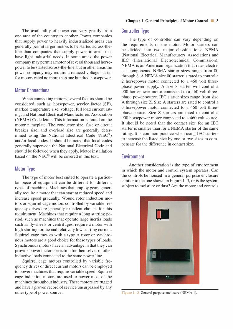
related and must be considered as a unit. Some machineswill have the motor or motors and control equipmentmounted on the machine itself when it is delivered fromthe manufacturer, and the electrician’s job in this case isgenerally to make a simple power connection to themachine. A machine of this type is shown in Figure 1–2.Other types of machines require separately mounted mo-tors that are connected by belts, gears, or chains. Somemachines also require the connection of pilot sensingdevices such as photo switches, limit switches, pressureswitches, and so on. Regardless of how easy or complexthe connection is, several factors must be considered.
Power SourceOne of the main considerations when installing a
machine is the power source. Does the machine re-quire single-phase or three-phase power to operate?
2 Chapter 1 General Principles of Motor Control
What is the horsepower of the motor or motors to beconnected? What is the amount of in-rush current thatcan be expected when the motor starts? Will the mo-tor require some type of reduced voltage starter to
limit in-rush current? Is the existing power supplycapable of handling the power requirement of the ma-chine or will it be necessary to install a new powersystem?
Figure 1–1 Motor controlled by a simple toggle switch. (Source: Delmar/Cengage Learning.)
Figure 1–2 This machine was delivered with self-contained motors and controls. (Courtesy of Simmons Machine Tool Co.)
ON
OFF
NEUTRAL CONDUCTOR
CIRCUIT BREAKER
SWITCH
+
+
HOTCONDUCTOR
Chapter 1 General Principles of Motor Control 3
Controller TypeThe type of controller can vary depending on
the requirements of the motor. Motor starters can be divided into two major classifications: NEMA (National Electrical Manufacturers Association) andIEC (International Electrotechnical Commission).NEMA is an American organization that rates electri-cal components. NEMA starter sizes range from 00through 8. A NEMA size 00 starter is rated to control a2 horsepower motor connected to a 460 volt three-phase power supply. A size 8 starter will control a 900 horsepower motor connected to a 460 volt three-phase power source. IEC starter sizes range from sizeA through size Z. Size A starters are rated to control a 3 horsepower motor connected to a 460 volt three-phase source. Size Z starters are rated to control a 900 horsepower motor connected to a 460 volt source.It should be noted that the contact size for an IECstarter is smaller than for a NEMA starter of the samerating. It is common practice when using IEC startersto increase the listed size by one or two sizes to com-pensate for the difference in contact size.
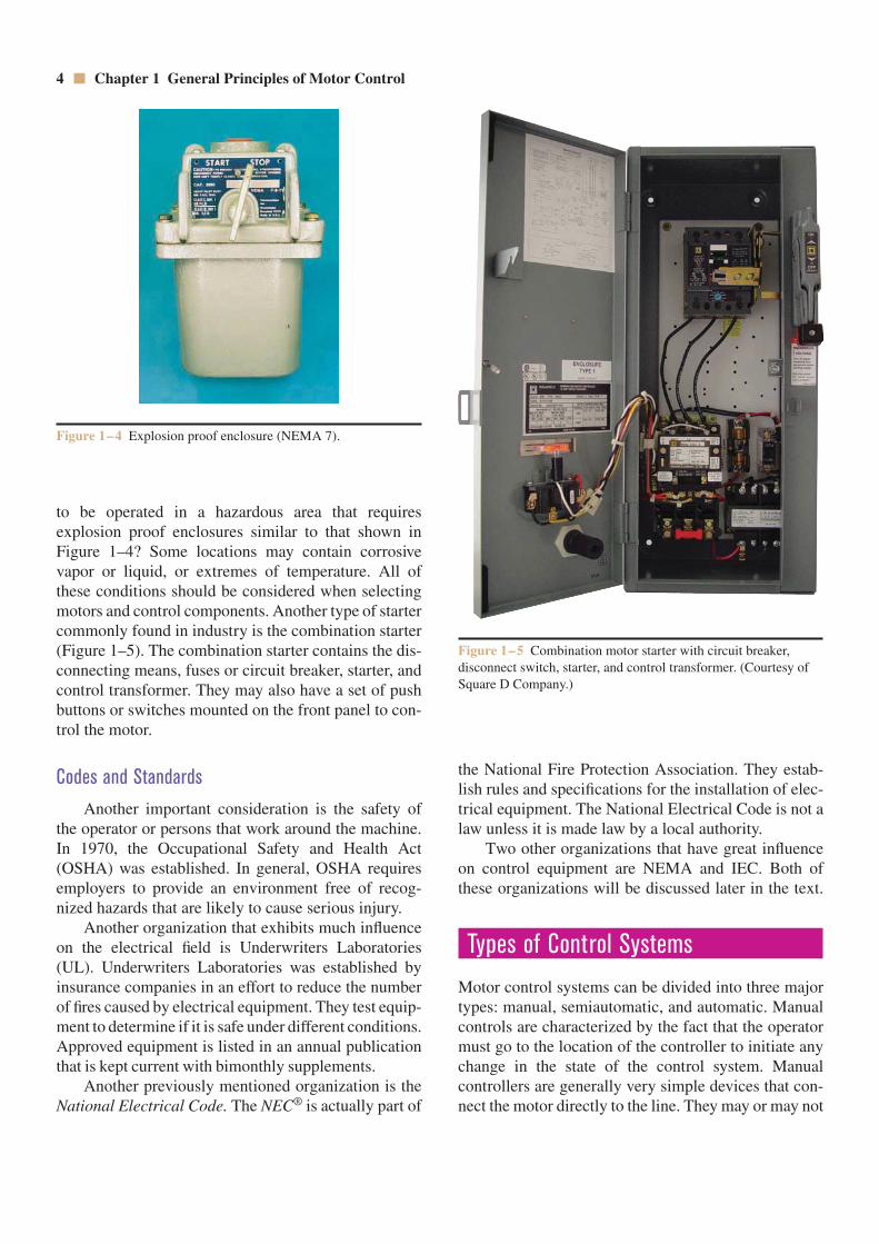
EnvironmentAnother consideration is the type of environment
in which the motor and control system operates. Canthe controls be housed in a general purpose enclosuresimilar to the one shown in Figure 1–3, or is the systemsubject to moisture or dust? Are the motor and controls
The availability of power can vary greatly fromone area of the country to another. Power companiesthat supply power to heavily industrialized areas cangenerally permit larger motors to be started across-the-line than companies that supply power to areas thathave light industrial needs. In some areas, the powercompany may permit a motor of several thousand horse-power to be started across-the-line, but in other areas thepower company may require a reduced voltage starterfor motors rated no more than one hundred horsepower.
Motor ConnectionsWhen connecting motors, several factors should be
considered, such as: horsepower, service factor (SF),marked temperature rise, voltage, full load current rat-ing, and National Electrical Manufacturers Association(NEMA) Code letter. This information is found on themotor nameplate. The conductor size, fuse or circuitbreaker size, and overload size are generally deter-mined using the National Electrical Code (NEC®)and/or local codes. It should be noted that local codesgenerally supersede the National Electrical Code andshould be followed when they apply. Motor installationbased on the NEC® will be covered in this text.
Motor TypeThe type of motor best suited to operate a particu-
lar piece of equipment can be different for differenttypes of machines. Machines that employ gears gener-ally require a motor that can start at reduced speed andincrease speed gradually. Wound rotor induction mo-tors or squirrel cage motors controlled by variable fre-quency drives are generally excellent choices for thisrequirement. Machines that require a long starting pe-riod, such as machines that operate large inertia loadssuch as flywheels or centrifuges, require a motor withhigh starting torque and relatively low starting current.Squirrel cage motors with a type A rotor or synchro-nous motors are a good choice for these types of loads.Synchronous motors have an advantage in that they canprovide power factor correction for themselves or otherinductive loads connected to the same power line.
Squirrel cage motors controlled by variable fre-quency drives or direct current motors can be employedto power machines that require variable speed. Squirrelcage induction motors are used to power most of themachines throughout industry. These motors are ruggedand have a proven record of service unsurpassed by anyother type of power source. Figure 1–3 General purpose enclosure (NEMA 1).
to be operated in a hazardous area that requires explosion proof enclosures similar to that shown inFigure 1–4? Some locations may contain corrosivevapor or liquid, or extremes of temperature. All ofthese conditions should be considered when selectingmotors and control components. Another type of startercommonly found in industry is the combination starter(Figure 1–5). The combination starter contains the dis-connecting means, fuses or circuit breaker, starter, andcontrol transformer. They may also have a set of pushbuttons or switches mounted on the front panel to con-trol the motor.
Codes and StandardsAnother important consideration is the safety of
the operator or persons that work around the machine.In 1970, the Occupational Safety and Health Act(OSHA) was established. In general, OSHA requiresemployers to provide an environment free of recog-nized hazards that are likely to cause serious injury.
Another organization that exhibits much influenceon the electrical field is Underwriters Laboratories(UL). Underwriters Laboratories was established byinsurance companies in an effort to reduce the numberof fires caused by electrical equipment. They test equip-ment to determine if it is safe under different conditions.Approved equipment is listed in an annual publicationthat is kept current with bimonthly supplements.
Another previously mentioned organization is theNational Electrical Code. The NEC® is actually part of
the National Fire Protection Association. They estab-lish rules and specifications for the installation of elec-trical equipment. The National Electrical Code is not alaw unless it is made law by a local authority.
Two other organizations that have great influenceon control equipment are NEMA and IEC. Both ofthese organizations will be discussed later in the text.
Types of Control Systems
Motor control systems can be divided into three majortypes: manual, semiautomatic, and automatic. Manualcontrols are characterized by the fact that the operatormust go to the location of the controller to initiate anychange in the state of the control system. Manualcontrollers are generally very simple devices that con-nect the motor directly to the line. They may or may not
4 Chapter 1 General Principles of Motor Control
Figure 1–4 Explosion proof enclosure (NEMA 7).
Figure 1–5 Combination motor starter with circuit breaker,disconnect switch, starter, and control transformer. (Courtesy ofSquare D Company.)
Chapter 1 General Principles of Motor Control 5
provide overload protection or low voltage release.Manual control may be accomplished by simply con-necting a switch in series with a motor (Figure 1–1).
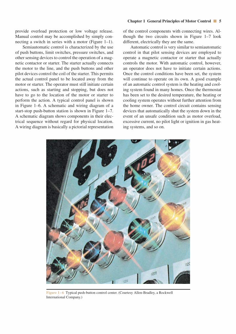
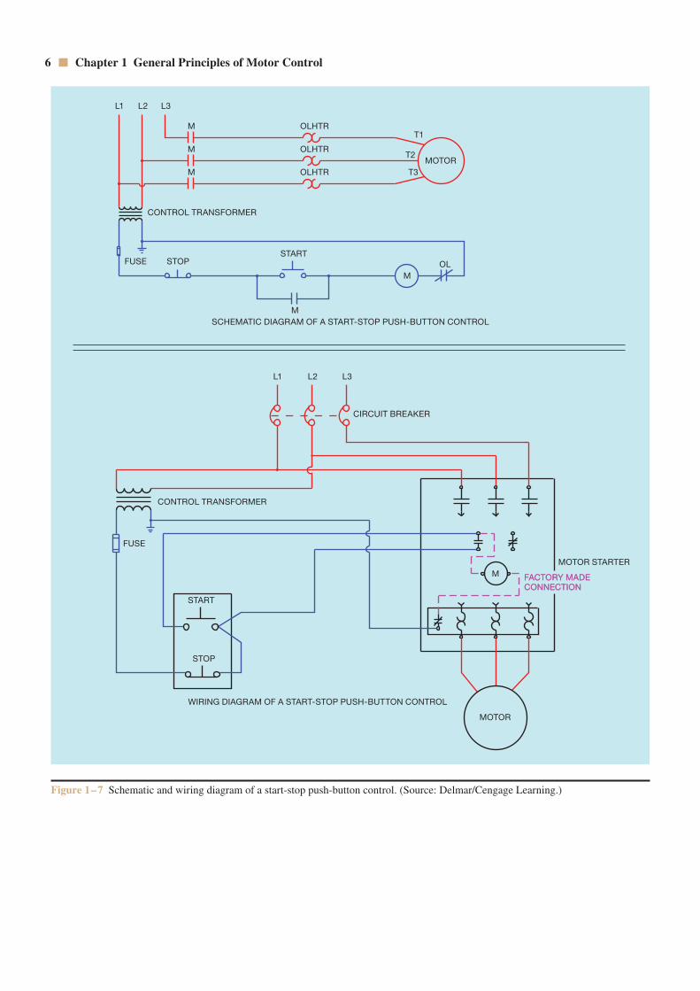
Semiautomatic control is characterized by the useof push buttons, limit switches, pressure switches, andother sensing devices to control the operation of a mag-netic contactor or starter. The starter actually connectsthe motor to the line, and the push buttons and otherpilot devices control the coil of the starter. This permitsthe actual control panel to be located away from themotor or starter. The operator must still initiate certainactions, such as starting and stopping, but does nothave to go to the location of the motor or starter toperform the action. A typical control panel is shown in Figure 1–6. A schematic and wiring diagram of astart-stop push-button station is shown in Figure 1–7.A schematic diagram shows components in their elec-trical sequence without regard for physical location. A wiring diagram is basically a pictorial representation
of the control components with connecting wires. Al-though the two circuits shown in Figure 1–7 look different, electrically they are the same.
Automatic control is very similar to semiautomaticcontrol in that pilot sensing devices are employed tooperate a magnetic contactor or starter that actuallycontrols the motor. With automatic control, however,an operator does not have to initiate certain actions.Once the control conditions have been set, the systemwill continue to operate on its own. A good example of an automatic control system is the heating and cool-ing system found in many homes. Once the thermostathas been set to the desired temperature, the heating orcooling system operates without further attention fromthe home owner. The control circuit contains sensingdevices that automatically shut the system down in theevent of an unsafe condition such as motor overload,excessive current, no pilot light or ignition in gas heat-ing systems, and so on.
Figure 1–6 Typical push-button control center. (Courtesy Allen-Bradley, a RockwellInternational Company.)
6 Chapter 1 General Principles of Motor Control
L1 L2 L3
M
M
M
OLHTR
OLHTR
OLHTR
T1
T2
T3MOTOR
M
M
OL
SCHEMATIC DIAGRAM OF A START-STOP PUSH-BUTTON CONTROL
CONTROL TRANSFORMER
FUSE STOPSTART
L1 L2 L3
CIRCUIT BREAKER
M
MOTOR
WIRING DIAGRAM OF A START-STOP PUSH-BUTTON CONTROL
FUSE
CONTROL TRANSFORMER
MOTOR STARTER
START
STOP
FACTORY MADECONNECTIONFACTORY MADECONNECTION
Figure 1–7 Schematic and wiring diagram of a start-stop push-button control. (Source: Delmar/Cengage Learning.)
Chapter 1 General Principles of Motor Control 7
Functions of Motor Control
There are some basic functions that motor control sys-tems perform. The ones listed below are by no means theonly ones, but are very common. These basic functionswill be discussed in greater detail in this text. It is im-portant not only to understand these basic functions of acontrol system, but also to know how control compo-nents are employed to achieve the desired circuit logic.
Star tingStarting the motor is one of the main purposes of a
motor control circuit. There are several methods thatcan be employed, depending on the requirements of thecircuit. The simplest method is across-the-line starting.This is accomplished by connecting the motor directlyto the power line. There may be situations, however,that require the motor to start at a low speed and accel-erate to full speed over some period of time. This is often referred to as ramping. In other situations, it maybe necessary to limit the amount of current or torqueduring starting. Some of these methods will be dis-cussed later in the text.
StoppingAnother function of the control system is to stop
the motor. The simplest method is to disconnect themotor from the power line and permit it to coast to astop. Some conditions, however, may require that themotor be stopped more quickly or that a brake hold aload when the motor is stopped.
Jogging or InchingJogging and inching are methods employed to
move a motor with short jabs of power. This is gener-ally done to move a motor or load into some desiredposition. The difference between jogging and inchingis that jogging is accomplished by momentarily con-necting the motor to full line voltage, and inching isaccomplished by momentarily connecting the motor toreduced voltage.
Speed ControlSome control systems require variable speed.
There are several ways to accomplish this. One of themost common ways is with variable frequency control
for alternating current motors, or by controlling thevoltage applied to the armature and fields of a directcurrent motor. Another method may involve the use ofa direct current clutch. These methods will be dis-cussed in more detail later in this text.
Motor and Circuit ProtectionOne of the major functions of most control systems
is to provide protection for both the circuit componentsand the motor. Fuses and circuit breakers are generallyemployed for circuit protection, and overload relays areused to protect the motor. The different types of over-load relays will be discussed later.
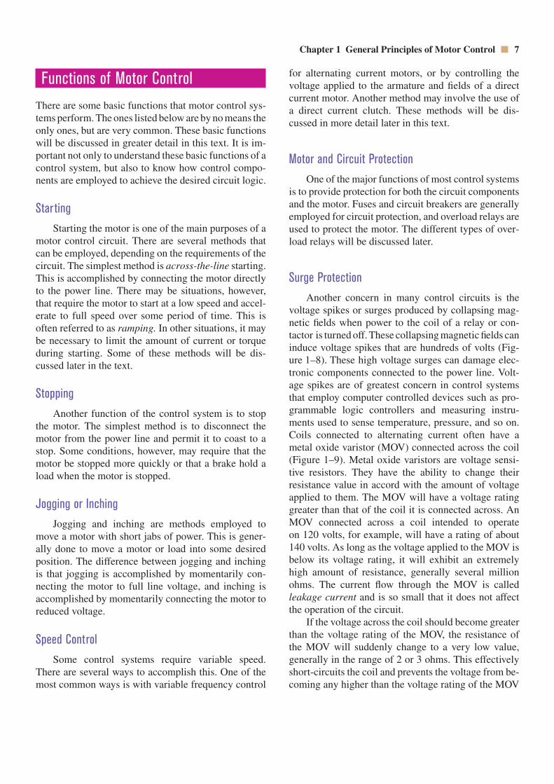
Surge ProtectionAnother concern in many control circuits is the
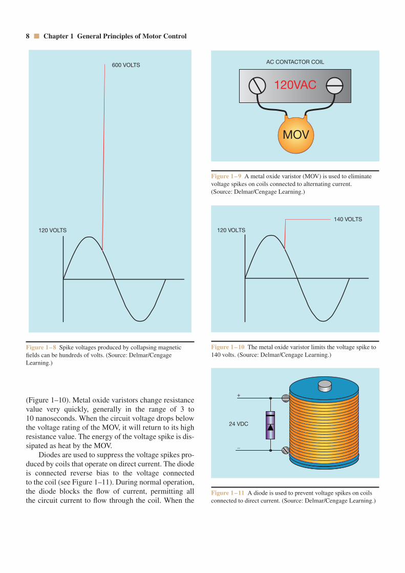
voltage spikes or surges produced by collapsing mag-netic fields when power to the coil of a relay or con-tactor is turned off. These collapsing magnetic fields caninduce voltage spikes that are hundreds of volts (Fig-ure 1–8). These high voltage surges can damage elec-tronic components connected to the power line. Volt-age spikes are of greatest concern in control systemsthat employ computer controlled devices such as pro-grammable logic controllers and measuring instru-ments used to sense temperature, pressure, and so on.Coils connected to alternating current often have ametal oxide varistor (MOV) connected across the coil(Figure 1–9). Metal oxide varistors are voltage sensi-tive resistors. They have the ability to change their resistance value in accord with the amount of voltageapplied to them. The MOV will have a voltage ratinggreater than that of the coil it is connected across. AnMOV connected across a coil intended to operate on 120 volts, for example, will have a rating of about 140 volts. As long as the voltage applied to the MOV isbelow its voltage rating, it will exhibit an extremelyhigh amount of resistance, generally several millionohms. The current flow through the MOV is calledleakage current and is so small that it does not affectthe operation of the circuit.
If the voltage across the coil should become greaterthan the voltage rating of the MOV, the resistance of the MOV will suddenly change to a very low value,generally in the range of 2 or 3 ohms. This effectivelyshort-circuits the coil and prevents the voltage from be-coming any higher than the voltage rating of the MOV
140 VOLTS
120 VOLTS
Figure 1–10 The metal oxide varistor limits the voltage spike to140 volts. (Source: Delmar/Cengage Learning.)
8 Chapter 1 General Principles of Motor Control
(Figure 1–10). Metal oxide varistors change resistancevalue very quickly, generally in the range of 3 to 10 nanoseconds. When the circuit voltage drops belowthe voltage rating of the MOV, it will return to its highresistance value. The energy of the voltage spike is dis-sipated as heat by the MOV.
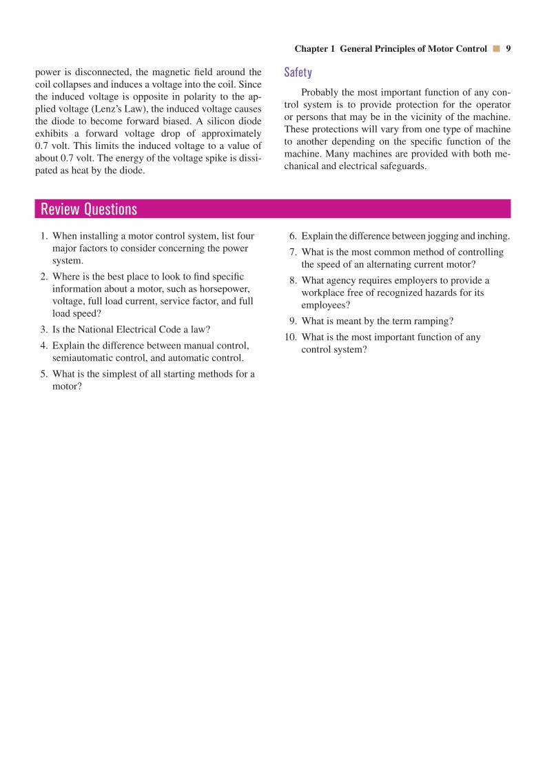
Diodes are used to suppress the voltage spikes pro-duced by coils that operate on direct current. The diodeis connected reverse bias to the voltage connected to the coil (see Figure 1–11). During normal operation,the diode blocks the flow of current, permitting all the circuit current to flow through the coil. When the
MOV
AC CONTACTOR COIL
120VAC
Figure 1–9 A metal oxide varistor (MOV) is used to eliminatevoltage spikes on coils connected to alternating current. (Source: Delmar/Cengage Learning.)
Figure 1–11 A diode is used to prevent voltage spikes on coilsconnected to direct current. (Source: Delmar/Cengage Learning.)
+
–
24 VDC
600 VOLTS
120 VOLTS
Figure 1–8 Spike voltages produced by collapsing magneticfields can be hundreds of volts. (Source: Delmar/CengageLearning.)
Chapter 1 General Principles of Motor Control 9
power is disconnected, the magnetic field around thecoil collapses and induces a voltage into the coil. Sincethe induced voltage is opposite in polarity to the ap-plied voltage (Lenz’s Law), the induced voltage causesthe diode to become forward biased. A silicon diodeexhibits a forward voltage drop of approximately 0.7 volt. This limits the induced voltage to a value ofabout 0.7 volt. The energy of the voltage spike is dissi-pated as heat by the diode.
SafetyProbably the most important function of any con-
trol system is to provide protection for the operator or persons that may be in the vicinity of the machine.These protections will vary from one type of machineto another depending on the specific function of themachine. Many machines are provided with both me-chanical and electrical safeguards.
Review Questions1. When installing a motor control system, list four
major factors to consider concerning the powersystem.
2. Where is the best place to look to find specific information about a motor, such as horsepower,voltage, full load current, service factor, and fullload speed?
3. Is the National Electrical Code a law?
4. Explain the difference between manual control,semiautomatic control, and automatic control.
5. What is the simplest of all starting methods for amotor?
6. Explain the difference between jogging and inching.
7. What is the most common method of controllingthe speed of an alternating current motor?
8. What agency requires employers to provide aworkplace free of recognized hazards for its employees?
9. What is meant by the term ramping?
10. What is the most important function of any control system?
10
OBJECTIVESAfter studying this chapter, the student will be able to:
Discuss symbols used in the drawing of schematic diagrams.
Determine the difference between switches that are drawn normally open,normally closed, normally open held closed, and normally closed held open.
Draw standard NEMA control symbols.
State rules that apply to schematic or ladder diagrams.
Interpret the logic of simple ladder diagrams.
CHAPTER 2SYMBOLS AND
SCHEMATIC DIAGRAMS
When you learned to read, you were first taught a set ofsymbols that represented different sounds. This set ofsymbols is called the alphabet. Schematics and wiringdiagrams are the written language of motor controls.Before you can learn to properly determine the logic of a control circuit, you must first learn the writtenlanguage. Unfortunately, there is no actual standardused for motor control symbols. Different manufactur-ers and companies often use their own sets of symbols for their in-house schematics. Also, schematics drawnin other countries may use entirely different sets ofsymbols to represent different control components.Although symbols can vary from one manufacturer to another, or from one country to another, once youhave learned to interpret circuit logic it is generallypossible to determine what the different symbols repre-
sent by the way they are used in the schematic. Themost standardized set of symbols in the United States is provided by the National Electrical Manufacturer’sAssociation, or NEMA. These are the symbols that wediscuss in this chapter.
Push Buttons
One of the most used symbols in control schematicsis the push button. Push buttons can be shown asnormally open or normally closed (Figure 2–1). Mostare momentary contact devices in that they make orbreak connection only as long as pressure is applied tothem. The pressure is generally supplied by someone’sfinger pressing on the button. When the pressure is