Embed Size (px)
Citation preview

The PerformanceController Manual
1999 Performance Control, LLC
4220 Varsity Drive, Suite EAnn Arbor, MI 48108-2241
(734) 975.9111 • fax (734) 975.9115


Table of Contents
Introduction 1
The Performance Controller 1Compatibility 2Today’s Power System Demands 2
The Power System 4
AC Induction Motors 5AC Induction Motor Control Techniques 6
AC Induction Motors – Today’s Design Problems 7
Horsepower Availability 7Voltage 7Summary 7Motor Losses 7Rewound Motors 8Energy Efficient Motors 8Measuring Energy Consumption 9
The Performance Controller Technology 10
Application of the Performance Controller 11
Introduction to the Motor Survey 11Procedure for the Motor Survey 11Survey Notes 12Analyzing Survey Results 12Survey Flow Chart 14Sizing the Performance Controller 15
Installation, Set-Up and Operation 16
Installation 16Set-up and Operation 16Operation 17
Performance Controller Troubleshooting 19
Installation & Maintenance of Motors 20
Safety Precautions 20Caveats 20Location/ Motor Enclosures 20Mounting 21Power Supply/Connections 21Wiring 22

Motor Troubleshooting Basics 23
Motor Start-up 23Nameplate 23Motor Starters and Compatibility 24Specialized Control Methods 24Starting 24Stopping 25Reversing 25Running 26Speed Control 26Safety of Operator 26Protection from Damage 26Overload Protection 26Over-travel Protection 26Over-speed Protection 26Mechanical Protection 27Open Field Protection 27Sequence Control Systems 27Reversed Phase Protection 28Short Circuit Protection 28Time Delay, Low Voltage Release 28Auto Transformer Starting 29Wye-Delta and Star-Delta Starting Systems 29Resistance Starting 30Dual-Speed, Dual-Torque, and Wound Rotor Motors 30Primary Resistor Starters 31Conclusions 32
Warranty 33


1© 1999 PerCon
Chapter 1
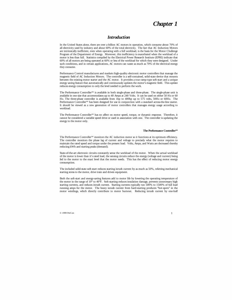
Introduction
In the United States alone, there are over a billion AC motors in operation, which consume about 70% ofall electricity used by industry and about 60% of the total electricity. The fact that AC Induction Motorsare intrinsically inefficient, even when operating with a full workload, is the basis for the Motor ChallengeProgram of the Department of Energy. Moreover, this inefficiency is exacerbated when the workload of amotor is less than full. Statistics compiled by the Electrical Power Research Institute (EPRI) indicate that60% of all motors are being operated at 60% or less of the workload for which they were designed. Undersuch conditions, and in certain applications, AC motors can waste as much as 70% of the electrical energythey consume.
Performance Control manufactures and markets high-quality electronic motor controllers that manage themagnetic field of AC Induction Motors. The controller is a self-contained, solid-state device that mountsbetween the existing motor starter and the AC motor. It provides a true ramp-type soft-start and a uniqueenergy saving feature that automatically and continuously updates the motor’s magnetic field. This updatereduces energy consumption to only the level needed to perform the work.
The Performance ControllerSM is available in both single-phase and three-phase. The single-phase unit isavailable in one size that accommodates up to 40 Amps at 240 Volts. It can be used on either 50 Hz or 60Hz. The three-phase controller is available from 1hp to 400hp up to 575 volts, 50Hz or 60Hz. ThePerformance ControllerSM has been designed for use in conjunction with a standard across-the-line starter.It should be viewed as a new generation of motor controllers that manages energy usage according toworkload.
The Performance ControllerSM has no affect on motor speed, torque, or dynamic response. Therefore, itcannot be considered a variable speed drive or used in association with one. The controller is updating theenergy to the motor only.
The Performance ControllerSM
The Performance ControllerSM monitors the AC induction motor so it functions at its optimum efficiency.The controller monitors the phase lag of current and voltage to precisely what the motor requires tomaintain the rated speed and torque under the present load. Volts, Amps, and Watts are decreased therebyreducing kWh and starting peaks (demand).
State-of-the-art electronic circuits constantly sense the workload of the motor. When the actual workloadof the motor is lower than it’s rated load, the sensing circuits reduce the energy (voltage and current) beingfed to the motor to the exact level that the motor needs. This has the effect of reducing motor energyconsumption.
The included solid-state soft-start reduces starting inrush current by as much as 50%, relieving mechanicalstarting stress to the motor, drive train and driven equipment.
Both the soft-start and energy-saving features add to motor life by lowering the operating temperature ofthe motor in the range of 10° to 40°F. Soft-starting reduces insulation damage, prevents unnecessary highstarting currents, and reduces inrush current. Starting currents typically run 500% to 1500% of full loadrunning amps for the motor. The heavy inrush current from hard-starting produces “hot-spots” in themotor windings, which directly contribute to motor burnout. Reducing inrush current by one-half

2 © 1999 PerCon
significantly lowers heat buildup in a motor, particularly when the motor is “duty-cycled” by an EnergyManagement System (EMS) or stopped and started frequently.
The Performance ControllerSM is compatible with: The Performance ControllerSM is not compatible with:
Time-delay, Low Voltage Release Relay(used in combination with Across-the-Line)
Two-Speed, One Winding (consequent pole)AC Induction Motors
Basic Wound Rotor AC Motors(except hoisting equipment)
Four-Speed, Two Winding (consequent pole)AC Induction Motors
Star-Delta AC Induction Motors Synchronous Motors
Two-Speed, Two-Winding AC Induction Motors DC Motors
Standard and Premium Efficiency Motors Eddy Current Drives
Part Winding Motors Adjustable Speed Drive Systems
Across-the-Line Starters (Jogging) AC Reduced Voltage Starters (Inching)
Sequence Controllers (controller for each motor) Auto Transformer Starters
AC Induction Motors manufactured after 1964* Part Winding Starters
Phase Failure Relays Primary Resistor
Multiple Push Button Stations Dynamic & Regenerative Braking
Interlocking Reverse Controls Electronic Braking
Plugging Switches
AC & DC Electric Brakes(line side of Performance ControllerSM)
*Motors manufactured prior to 1964 (U Frame) are compatible presuming survey information is accurately detailed.
Today’s Power System Demands
Revolutionary changes in modern power consuming equipment have enabled technology to use energymore effectively than ever before. The Performance ControllerSM is at the forefront of these technologicaladvances. With progress must come the realization that the power distribution system within a facility isgoing to be required to support systems that rely on microprocessor technology, which converts the ACsine wave in some fashion. For example, in the 1960’s, the electrical system in your car was a simpleformat for accomplishing engine operation. Today, your automobile’s electrical system is amicroprocessor-based control system that not only controls the basic engine functions, but also the flow offuel for better economy, safety systems such as ABS and many other functions. With this, yourautomobile’s electrical distribution system has been adapted to handle additional signaling and control.
The electrical distribution system in your facility must also be prepared for additional signaling andcontrol. The term for this is Power Quality, which by definition is the delivery (by means of subsystems) ofclean power to equipment. Most important, as has been the case for many years, are good grounding,proper transformer location, and transient protection. All of these should be standard in any properlywired facility.
Unfortunately, most electrical distribution systems have been modified by multiple companies and thesemodifications have not been recorded. It must be stressed that the importance of good wiring practicesand adequate knowledge of your facility’s power requirements are important to the successful continuedoperation of your equipment.
Your power system will react to the loads placed on it and, more importantly, to electronic loads. Youmust be prepared to accommodate this new breed of loads. You may have an existing problem with yourpower system that will only show up after a sensitive load has been placed on it.

3© 1999 PerCon
The Performance ControllerSM is not a sensitive electronic load; rather it is a field-tested workhorse similarto the “dirty” motors that have given you no trouble for years. Nonetheless, you will be applying a hightechnology device to a motor, and applying it properly is the key to its success.

4 © 1999 PerCon
Chapter 2
The Power System
Typically, the voltage from the utility is higher (for transmitting long distances) than practically usable infacilities. These voltage levels need to be transformed to lower usable voltages for end user facilities.Transformers reduce the voltage to four or five combinations, depending on the type of facility beingpowered. All electrical power supplied as AC for industrial and residential use is generally 60Hz and fewerthan 600 volts. The two most widely used combinations of three-phase power system voltages are:
Three-Phase, Four-Wire Wye System - 480/277 V
Three-Phase, Three Wire System
Other levels of common voltages are 575 and 460 volts. These are typically used in industrial applications.In addition, large companies will purchase power from the Utility at significantly higher voltages such as4,160 volts and 13,800 volts and transform the voltage with their own equipment (transformers) forreduced power prices. These companies also bear the burden of maintaining the high voltage equipment.
Commercial and industrial applications are typically three-phase, but in most cases require two levels ofvoltage. Motors and commercial lighting systems are best run on 480/277 while the office equipment suchas computers and copiers require 208/120. The main reason for using two types of voltage levels infacilities is size of equipment. Higher voltage equipment is generally smaller and the conductors thatsupply the power are smaller as well.
It is very important to understand the voltage with which you are working, first for safety and second for theapplication of the Performance ControllerSM. If it is necessary to take measurements or information from exposedelectrical wiring, you should attain the services of a licensed electrician or qualified maintenance person.
Ground
A B
C
Neutral
277 V
277 V277 V
480 V480 V
480 V
A
B
C
240 or480 V 240 or
480 V
240 or 480 V

5© 1999 PerCon
AC Induction Motors
All three-phase motors are constructed internally with a number of individually wound electrical coils.Regardless of how many individual coils there are in a three-phase motor, the individual coils will alwaysbe wired together (series or parallel) to produce three distinct windings which are called phases. Eachphase will always contain one-third of the total number of individual coils. These composite windings orphases are usually referred to as phase A, phase B, and phase C.
Three-phase motors vary from fractional horsepower to several thousand horsepower. These motors have afairly constant speed characteristic, but a wide variety of torque characteristics. They are made forpractically every standard voltage and frequency and are often dual-voltage motors. The three-phase motoris probably the simplest and most rugged of all electric motors. To get a proper perspective of howimportant the three-phase motor is, remember that this motor is used in nine out of ten industrialapplications.
In a three-phase induction motor, there are three sets of windings on the stator frame arranged to producea revolving magnetic field when connected to a three-phase source. The rotor (rotating component)consists of steel laminations mounted rigidly on the motor shaft. Copper or aluminum bars are placed orcast in slots of the laminated steel core to form the rotor winding (in contrast to the copper wire coilsfound in many other motor types). The stator bars are interconnected by short-circuited rings, whichrepresent a short circuit closed loop.
When the cutting lines of magnetic force originating in the stator cross into these short-circuited bars ofthe rotor, a voltage is induced into the rotor by transformer action resulting in a heavy current flow in therotor. Induced voltages from transformer action will be reverse polarity to the voltage creating it. This inturn will result in a magnetic field opposite to that of the stator. The combined electromagnetic effects ofthe stator and rotor currents and their magnetic fields produce the torque of force to create rotation.
It should be noted that when the rotor is inserted into the stator, the air gap between the rotor and stator iskept extremely small in order to increase efficiency.
The squirrel-cage motor is basically a constant speed device. It cannot operate for any appreciable periodof time at speeds below those shown on the nameplate without danger of high heat and burnout.
Three-phase wye and three-phase delta wired motors:
T3T2
T1
Motor Starter
L1 L2 L3
PhaseA
PhaseC
PhaseB
Wiring diagram of a three-phase motorwired in a Wye (Y) configuration.
O.L.
T3T2T1
L3L2L1
Motor Starter
L1 L2 L3
PhaseA
Phase B
PhaseC
Wiring diagram of a three-phase motorwired in a Delta (∆∆) configuration.
O.L.

6 © 1999 PerCon
AC Induction Motor Control Techniques
There are certain conditions that must be considered when selecting, designing, installing, or maintainingelectric motor control equipment. Motor control was a simple problem when motors were used to drive acommon line shaft to which several machines were connected. It simply started and stopped the motor afew times a day. However, with individual drive, the motor is now an integral part of the machine. It isnow necessary to design the motor controller to fit the needs of the machine to which it is connected.
Motor control is a broad term that means anything from a simple toggle switch to a complex system withcomponents such as relays, contactors, timers, and switches. The common function of all controls,however, is to control the operation of an electric motor. As a result, when motor control equipment isselected and installed, many factors must be considered to insure that the control will function properly forthe motor and the machine for which it is selected.
7© 1999 PerCon
Chapter 3
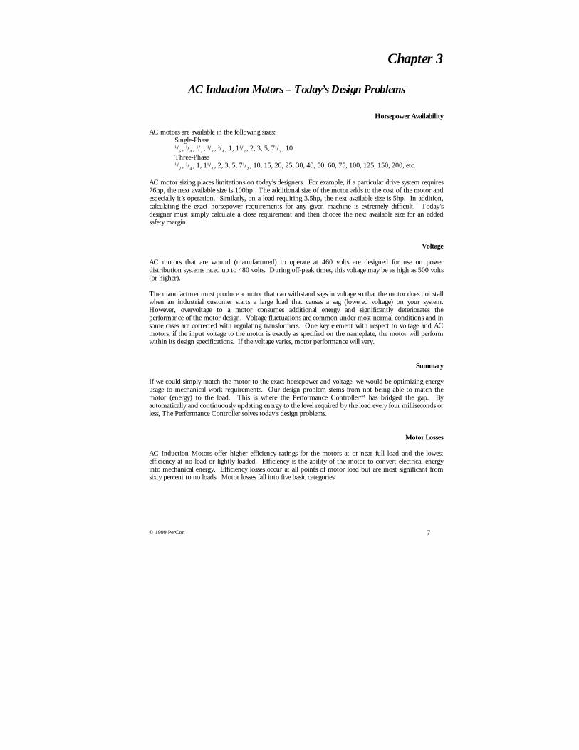
AC Induction Motors – Today’s Design Problems
Horsepower Availability
AC motors are available in the following sizes:Single-Phase1/6 ,
1/4 , 1/3 ,
1/2 , 3/4 , 1, 11/2 , 2, 3, 5, 71/2 , 10
Three-Phase1/2 ,
3/4 , 1, 11/2 , 2, 3, 5, 71/2 , 10, 15, 20, 25, 30, 40, 50, 60, 75, 100, 125, 150, 200, etc.
AC motor sizing places limitations on today’s designers. For example, if a particular drive system requires76hp, the next available size is 100hp. The additional size of the motor adds to the cost of the motor andespecially it’s operation. Similarly, on a load requiring 3.5hp, the next available size is 5hp. In addition,calculating the exact horsepower requirements for any given machine is extremely difficult. Today’sdesigner must simply calculate a close requirement and then choose the next available size for an addedsafety margin.
Voltage
AC motors that are wound (manufactured) to operate at 460 volts are designed for use on powerdistribution systems rated up to 480 volts. During off-peak times, this voltage may be as high as 500 volts(or higher).
The manufacturer must produce a motor that can withstand sags in voltage so that the motor does not stallwhen an industrial customer starts a large load that causes a sag (lowered voltage) on your system.However, overvoltage to a motor consumes additional energy and significantly deteriorates theperformance of the motor design. Voltage fluctuations are common under most normal conditions and insome cases are corrected with regulating transformers. One key element with respect to voltage and ACmotors, if the input voltage to the motor is exactly as specified on the nameplate, the motor will performwithin its design specifications. If the voltage varies, motor performance will vary.
Summary
If we could simply match the motor to the exact horsepower and voltage, we would be optimizing energyusage to mechanical work requirements. Our design problem stems from not being able to match themotor (energy) to the load. This is where the Performance ControllerSM has bridged the gap. Byautomatically and continuously updating energy to the level required by the load every four milliseconds orless, The Performance Controller solves today’s design problems.
Motor Losses
AC Induction Motors offer higher efficiency ratings for the motors at or near full load and the lowestefficiency at no load or lightly loaded. Efficiency is the ability of the motor to convert electrical energyinto mechanical energy. Efficiency losses occur at all points of motor load but are most significant fromsixty percent to no loads. Motor losses fall into five basic categories:

8 © 1999 PerCon
Loss % General Causes1. Stator Losses I2R 35-40 % Stator Conductor Size2. Rotor Losses I2R 15-20 % Rotor Conductor Size3. Core Losses 15-20 % Type, Quantity of Magnetic Material4. Stray Load Losses 10-15 % Manufacturing, Design Methods5. Friction/Windage 5-10 % Selection/Design of Fans and Bearings
This is where the Performance Controller saves energy!
Stator and Rotor Losses vary with motor loading. Current flowing through the motor winding produceslosses, which are proportional to the current squared, times the winding resistance.
Core Losses (iron losses) are essentially independent of the load. These losses are confined mainly to thelaminated core of the stator and rotor. The magnetic fields, essential to the production of torque in themotor, cause hysteresis and eddy current losses. Core losses usually constitute the bulk of energy losses.
Stray and Load Losses are dependent on load. Several minor losses include leakage flux, non-uniformcurrent distribution, air gap, and so forth. These losses increase with load.
Friction and Windage are independent of other losses. Mechanical losses occur in the bearings and fans ofmotors and are usually minor losses.
Rewound Motors
During a motor failure or in the stripping of the winding from the stator core prior to rewinding, hightemperatures can occur. These temperatures can, in many cases, affect the electrical characteristics of thestator core steel and result in increased iron losses and lowered motor efficiency. An indication that themotor has been rewound is a label applied by the motor shop. Usually the date is stamped on the label. Ifthe motor has been rewound, the user will never know if the motor winding stripping process exceeded themanufacturer’s temperature limits.
Energy Efficient Motors
New government regulations are forcing industrial motor users to focus, and eventually use, more energyefficient motors. This new generation of motors is bred from gains in the manufacturing process itself.Five types of efficiency losses in motor have been addressed:
• Iron Losses - Use of thinner gauge, lower loss core steel reduces eddy current losses. Longer cores add more steelto the design, which reduces losses due to lower operating flux densities.
• Stator I2R - Use of more copper and larger conductors increases cross sectional area of stator windings. Thislowers resistance of the windings and reduces losses due to current flow.
• Rotor I2R - Use of larger rotor conductor bars increases size of cross section, lowering conductor resistance andlosses due to current flow.
• Friction/Windage - Use of new lubrication systems low-loss fan design reduces losses due to bearing friction andair movement.
• Stray Load Loss - Optimizing design and strict quality control procedures minimizes stray load losses.
If you are considering replacement of standard efficiency motors with premium efficiency, first look at thecost comparison using either a simple payback or a formal present value analysis (PVA). Simple payback iscalculated by the following formulas:

9© 1999 PerCon
Watts Loss = Input - Output = HP x 746 ÷ Efficiency - (HP x 746)
Watts Loss for a 88.3% Efficient Motor = 25 x 746 ÷ 0.883 - (25 x 746) = 2471 WattsWatts Loss for a 93.6% Efficient Motor = 25 x 746 ÷ 0.936 - (25 x 746) = 1275 Watts
The above shows that a 25hp energy efficient motor saves 1196 watts (2471-1275) at full load, underlaboratory conditions. It is important to consider the inrush current of a premium efficiency motor will besignificantly higher than standard efficiency. Attention must be paid to the size of the starting circuit for apremium efficiency motors and in most cases, the motor circuit will need to be upgraded unless thePerformance ControllerSM is used to soft-start (reduce) these high inrush current motors.
Premium efficiency motors have taken most of the attainable energy losses out of the design problem.However, four problems still remain; exact horsepower, exact voltage, inrush starting, and most important,under-loading. With the proper application, significant savings can be achieved by applying thePerformance ControllerSM to premium efficiency motors.
Measuring Energy Consumption
The formula for measuring energy consumption in a three-phase AC Induction Motor is calculating theenergy consumed (watts):
E x I x Power Factor x 1.73 = kW1000
10 © 1999 PerCon
Chapter 4
Performance Controller Technology
The Controller performs a number of functions electronically. An explanation of each follows:
Energy savings is achieved by means of a closed loop feedback system. The sensing circuits in theController compare the voltage and current waveforms at the motor. Because this is an induction circuit,the voltage and current waveforms start at different times. The smaller the load on the motor, the greaterthe lag in the current waveform. At no load, the motor is least efficient and the waveforms have the largestdistance between them. We measure the distance between the two and compare this difference to anoperational distance. The difference between the actual waveforms and the ideal is compared and gives usa sum that we call the error voltage. This error voltage is used to create a firing pulse that determines thelength of time we send power to the motor. The larger the error voltage, the shorter the firing pulse. Thesmaller the error voltage, the longer the ‘on’ time of the firing pulses.
In this manner we can regulate the amount of energy that the motor receives to perform it’s work. Thespeed of the circuit is such that it can change the signal to the motor one hundred twenty times per second(twice the sixty-cycle frequency). This speed is much faster than the motor can operate, and is necessary tokeep the motor from stalling under any and all motor functions.
Soft-start is achieved by the use of a timed ramp circuit. The circuit gradually releases power to the motorin a timed manner. As voltage is slowly increased, current is gradually increased as needed by the motoruntil full voltage and current bring the motor to its full rpm. Soft-start can be adjusted from aninstantaneous start to 30 seconds before full rpm and, therefore, full voltage can be reached. Typical soft-start results offer reductions of 40% to 50%.
11© 1999 PerCon
Chapter 5
Application of the Performance Controller
Introduction to the Motor Survey
Energy cannot be reduced on a motor that is performing work at its rated load.
Simply stated, a motor that is producing work at or near its design level needs energy to operate. Gains inmotor energy conservation can occur at unloaded intervals (or during the unloading cycle) of the drivenmachine. Energy conservation is the removal of waste energy (Motor Losses, pages 7 & 8) while stillperforming necessary work. This is the most important fact of the Performance ControllerSM.
The Performance ControllerSM achieves savings by updating the motor field in one quarter of one electricalcycle, once every half cycle. This function of the controller offers the ability to conserve energy at anunparalleled rate of speed. That is, on a driven system that quickly loads and unloads, energy is increasedor reduced as the motor loads and unloads. When the motor unloads, losses occur and the controllerremoves the losses.
Completing the motor survey form is the most important part of your success in energy conservation.Keep in mind how the controller functions, losses must be occurring. Your primary goal in the survey is toidentify motors that are cyclical (load and unload), oversized, over-voltaged, and constant speed. You arenot looking for motors that have failed or are prone to breakdown as the Performance ControllerSM is not aremedy for problem motors. It is important to look for constant speed, variable load, a large watt pool (bigmotor), and a low power factor.
Selecting applications for energy conservation with the Performance ControllerSM involves a few initialquestions:
Consider the work being performed by the motor.a. Is the motor unloaded for a longer period of time than its loaded cycle (i.e. low PF)?b. Is the motor’s horsepower greater than necessary?c. Does the motor have a constant speed application?d. Does the motor use a special starting or wiring system?
If your answers to these initial questions are:a. Yes, the PF is low (0.40 or less) longer than it is high (0.40 or more).b. Yes, it is an oversized motor.c. Yes, it is constant speed, variable load.d. No, the motor does not use reduced voltage or other special starters.
Continue on to the Motor Survey using the survey form located at the rear of this manual.
Procedure for Completing the Motor Survey Form
Safety tip: Serious injury or death may result from exposure to energized equipment. Licensing is required by law in most states.
Once you have the necessary tools, performing a survey on a motor should take approximately twenty tothirty minutes, given that the control system is at or near ground level and you are an experiencedelectrician. If you are not an electrician or a qualified motor service technician, locate one that can offerassistance.
12 © 1999 PerCon
Required tools to perform a Motor Survey are as follows: A Power Meter capable of three-phase volts,amps, watts, and Power Factor, a Performance Control AC Motor Survey Form (one is provided at theend of this manual), and an electrician or qualified maintenance representative.
Performing a survey requires knowledge of electrical motor systems and controls. Terminology used inthis section is based on the assumption that the surveyor has a high level of understanding of this subject.
• Discuss your survey with a plant manager and inquire if there are any company policies or laborregulations that you should be aware of.
• With a clipboard and the Performance Control Survey Form, approach the motor you would like tosurvey and determine that it is an AC Induction Motor.
• Complete the first block of the survey with as much information as available, with particular attentionto the driven systems function.
• Obtain all nameplate information and any additional stickers or tags added to the motor during itsservice life. Additional tags usually represent rewind dates or major service information.
• Determine the type of starting system, This is a very important step. See Specialized Control Methodson page 24.
• Take measurements as close to the motor as practically possible, making absolutely sure that there isnothing installed between where you are measuring and the motor itself. Record these measurementson the motor survey form. You can perform two surveys per form.
Survey Notes
Be aware and make note of surrounding equipment such as capacitor banks, cooling systems, brakingsystems, and other special purpose equipment. If you encounter special purpose equipment, create a one-line diagram on the back of the survey sheet with detailed information as you may have a compatibilityproblem.
Once your survey is complete, you are ready to look at the results and determine if your motor is acandidate for energy conservation.
Analyzing Survey Results
With exception to anomalies that occur on pumps and fans, motor loading (the ability to conserve energy)can be estimated with your survey results. Working with the measurements that were taken, we are goingto pose the following questions:
1. If the voltage is higher than the nameplate rating, how much higher is it?
For example, your measurement has determined that the input voltage is 484 VAC, and your nameplateinformation reveals the motor is wound for 460 VAC. The difference is 24 VAC, and if we apply thePerformance ControllerSM, the voltage is reduced to 460 VAC (or less when unloading) and the differenceadjusted by the wattage formula for motors is savings. Another consideration with respect to voltage is thatit is usually much higher during off-peak hours which translates to more savings during evening operation.
2. What is the percent difference in amperage between nameplate full load amps and your measurement?
Full load amps (FLA) listed on the nameplate of the motor are established by the manufacturer of themotor. This is the maximum allowable amps and is used to size over-current protection, conductors,

13© 1999 PerCon
piping, and the motor starter itself. Although amperage is not an exact delineation, it does indicate thepossibility that a motor is not operating at full load.
3. What are the operating watts through the loading cycle?
You will be able to compare wattage measurements after installation of the Performance ControllerSM.
4. What is the Power Factor of the motor through the loading cycle?
The power factor improves as the AC induction motor approaches its designed operating load. Poorpower factor in most cases represents a lightly loaded motor. Most motors will rarely achieve a powerfactor of .85 and most often exhibit power factor readings of .50 to .70. Generally speaking, a motor witha power factor of .40 or lower represents a good candidate for the Performance ControllerSM. Remembereach motor is unique in that it will have its own power factor characteristics. Power factor is discussed inan enclosed article in the Reference section of the manual. (More time at a low PF translates to a bettercandidate for energy savings.)

14 © 1999 PerCon
ACmotor
Yes
Motor found
Locate ACinduction
motors onlyNo
Provide detailedSurvey
information
1964 or Later
Nameplatefound?
CompleteSurvey
Yes
Across-the-line Starter?
Proceed toAnalyzing Resultsin Manual, p. 12
Yes No
Do resultsshow goodapplication?
Apply Perfor-mance Controller
at own risk
No
Size Controller
Yes
ApplyPerformance
Controller
Proceedto nextmotor
No
Survey Flow Chart
Takemeasurements
Yes No
Apply tomotor at own
risk.
No Yes
15© 1999 PerCon
Sizing the Performance ControllerSM
Once you are comfortable with the survey results and have selected a motor for retrofit, then look at theapplication for electrical sizing.
Sizing the Performance ControllerSM is based on motor horsepower and amperage. Most cases will rely onthe standard horsepower format. However, field-testing may indicate an overloaded motor, which willincrease the required amperage rating. This condition would require a special order controller, sized forthe overload condition. If you encounter an overloaded motor:
1. Check all feeder systems to maintain NEC ratings for over-current protection and conductor(including new de-rating schedules).
2. Check the operating temperature of the motor for excessive heat buildup.
3. Inform the facility management that this condition exists and needs to be addressed.
4. Consider replacement of the motor with the proper size.
5. Order the appropriate size for the overload condition.
Overload conditions can occur on an unloaded motor when the motor is suddenly slammed into service.An example would be a press that may be pressing material beyond its rating.
The Performance ControllerSM is designed to handle overload conditions. It is also designed to handleoverload conditions while still conserving energy when the motor is unloaded or unloading. It will benecessary to provide detailed measurement information for applications involving overloaded conditions.
The appropriate action for this condition is to properly size the SCR component of the PerformanceControllerSM. Failure to do so will void the warranty.
16 © 1999 PerCon
Chapter 6
Installation, Set-Up and Operation
Installation
The installation process is similar to any ordinary electrical distribution component. All NEC and localcodes including licensing, permits, and inspection regulations apply. A few very important instructions areneeded:
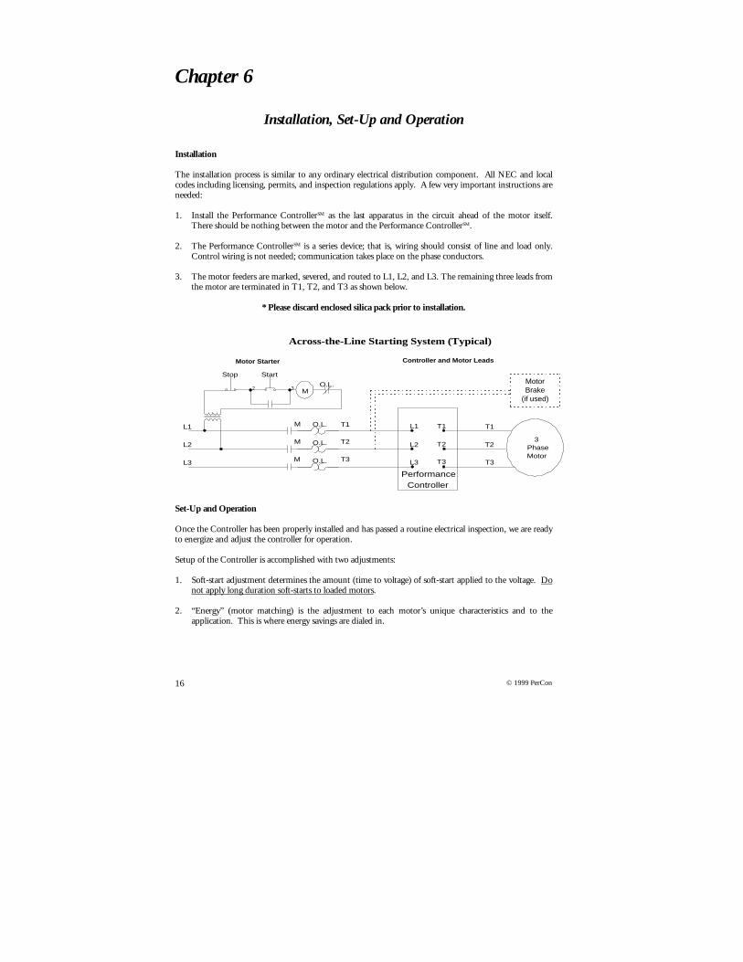
1. Install the Performance ControllerSM as the last apparatus in the circuit ahead of the motor itself.There should be nothing between the motor and the Performance ControllerSM.
2. The Performance ControllerSM is a series device; that is, wiring should consist of line and load only.Control wiring is not needed; communication takes place on the phase conductors.
3. The motor feeders are marked, severed, and routed to L1, L2, and L3. The remaining three leads fromthe motor are terminated in T1, T2, and T3 as shown below.
* Please discard enclosed silica pack prior to installation.
Set-Up and Operation
Once the Controller has been properly installed and has passed a routine electrical inspection, we are readyto energize and adjust the controller for operation.
Setup of the Controller is accomplished with two adjustments:
1. Soft-start adjustment determines the amount (time to voltage) of soft-start applied to the voltage. Donot apply long duration soft-starts to loaded motors.
2. “Energy” (motor matching) is the adjustment to each motor’s unique characteristics and to theapplication. This is where energy savings are dialed in.
2 3 MO.L.
T1
Stop Start
PerformanceController
T2
T3M
M
M O.L.
O.L.
O.L. L3
L2
L1 T1
T2
T3
L1
L2
L3
T1
T2
T3
Controller and Motor LeadsMotor Starter
3PhaseMotor
Across-the-Line Starting System (Typical)
MotorBrake
(if used)
17© 1999 PerCon
Starting the Controller for the First Time
1. With the Controller in bypass, start the motor with the across-the-line starter (if not across-the-linerefer to Motor Starters and Compatibility Section) and check for proper rotation.
2. Follow the steps outlined in Motor Start-Up on page 23, checking for unusual events. If motor start-up confirms no problems continue to step 3.
3. Cut off all power to motor and starter (de-energize the motor).
4. Place the Performance ControllerSM in “service” by turning the bypass switch to the “Normal”position. (Never switch to and from bypass while the motor is running)
5. Adjust the “Soft-Start” to “25” or lower if the motor labors to start. Do not apply long duration soft-starts to loaded motors.
6. Adjust the “Energy” to “Min.”
7. Start the motor.
8. While monitoring the voltage meter on the panel of the Performance ControllerSM, follow theprocedures in Motor Start-Up on page 23, checking for unusual events.
9. Once the motor has run without event for five to ten minutes, gradually increase the “Energy”adjustment. While the motor is running, increasing the “Energy” adjustment decreases voltage andcurrent to the motor. This reduction is the elimination of motor losses discussed on page 7. If youreduce the “Energy” too much, the motor will “chatter” or “buck.” With an ammeter clamped to theprimary side of the Controller, and while increasing the “Energy” adjustment, amperage will go down.As Amps continue to fall, you will come to a point where Amps will start to rise, decrease theadjustment at this point slightly and you have properly adjusted The Controller. It is normal to seethe voltmeter on the unit tracking up and down with the loading and unloading of the motor.
10. Close and secure the cabinet, making sure machine operators and maintenance personnel have beennotified of the Performance Controller’sSM installation and operation procedures.
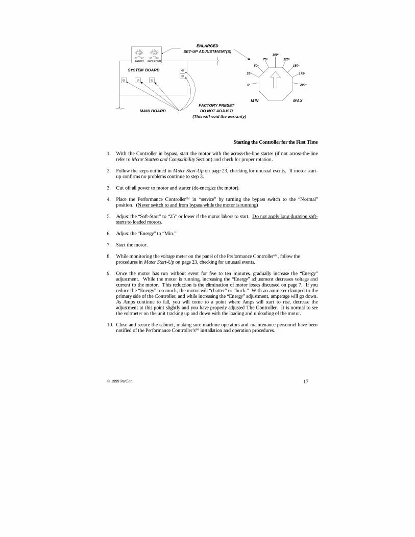
ENERGY SOFT-START
MIN MAX
SYSTEM BOARD
MAIN BOARDFACTORY PRESETDO NOT ADJUST!
(This will void the warranty)
ENLARGEDSET-UP ADJUSTM ENT(S)
MIN MAX
0O
25O
50O
75O
100O
125O
150O
175O
200O
M IN MAX

18 © 1999 PerCon
Operation
The Performance ControllerSM is fully automatic and will provide service for many years. A monthly checkof the voltage meter is all that is required to ensure trouble-free operation.
While the controller is operating the following conditions are normal:
1. The voltage meter is rising and falling as the motor loads and unloads.
2. When the motor is started, the voltage rises to full voltage and then falls back to the above condition.
If you replace the motor with another of equal or lesser size, the Performance Controller will need to beadjusted.
19© 1999 PerCon
Chapter 7
The Performance Controller Troubleshooting
y When the “Motor Start” button is depressed, the motor will not start.
• The power should have been de-energized for installation, so be sure to confirm that it has been re-energized.
• Some machines contain safety systems that need to be reset prior to energizing.• Some motors are energized by remote systems.• Incoming voltages must be the full nameplate rated voltage of the motor.• Make sure you have a standard motor starter (across-the-line).
y The motor soft-starts, but the energy circuits do not reduce the voltage and current that much.
• Does the application ‘”survey out” for potential energy savings outlined in the survey procedures.Voltage and current cannot be reduced on a fully loaded motor.
• Make sure you are on a compatible motor (listed on pages 4).• Gradually increase the “Energy” adjustment to reduce voltage and current.
y The motor soft-starts and then starts to make a chattering sound.
• The “Energy” level has been adjusted too high, so adjust toward “Min” until the chatter sound isgone. Chattering develops when you restrict voltage and current too much.
y Once the energy circuit reduces the voltage, the meter starts a rapid bounce.
• The “Energy” control is too high, so reduce it until the meter appears smooth. The meter shouldtrack up and down with the load.
• The motor may also be controlled by another device. Make certain that there are no other additionalmotor controls, especially those that reduce voltage.
y After being switched to “Bypass,” the motor makes a skipping sound.
• Never switch into “Bypass” or “Normal” while the motor is in operation.• De-energize the circuit, then make the transfer.

20 © 1999 PerCon
Chapter 8
Installation & Maintenance of Motors
Safety Precautions
Always use safe practices when handling, lifting, installing, operating, and maintaining motors and motoroperated equipment. Install motors and electrical equipment in accordance with the National ElectricalCode (NEC), local electrical safety codes and practices, and, when applicable, the Occupational Safety andHealth Act (OSHA). Ground motors securely and make sure that ‘grounding’ wires and devices are, infact, properly grounded. Before servicing or working on or near motors or motor driven equipment,disconnect the power source from the motor, accessories, and the lockout system.
1. Motors subjected to overload, locked rotor, current surge, or inadequate ventilation conditions mayexperience rapid heat buildup, presenting risk of motor damage or fire. To minimize such risks, use ofmotors with proper overload protection is advisable for all motors.
2. DO NOT use motors with automatic-reset protectors where automatic restarting might be hazardousto personnel or to equipment. Use motors with manual-reset protectors where such hazards exist.Such applications include conveyors, compressors, tools, most farm equipment, etc.
3. Remove shaft key from keyway of installed motors before energizing motor. Be sure keys, pulleys,fans, etc. are fully secured on installed motors before energizing motor.
4. Make sure fans, pulleys, belts, etc. are properly guarded if they are in a location that could behazardous to personnel.
5. Provide proper safeguards against failure to motor mounted brakes, particularly on applicationsinvolving overhauling loads.
6. Provide proper safeguards on an application where a motor is mounted on or through a gear reducerto a holding or overhauling application. Do not depend upon gear friction to hold the load.
7. Do not lift motor-driven equipment without motor lifting means. If eyebolts are used for liftingmotors, they must be securely tightened and the direction of the lift must not exceed a fifteen-degreeangle with the shank of the eyebolt.
Location/Motor Enclosures
1. Open, drip-proof motors are designed for areas that are reasonably dry, clean, and well ventilated,usually indoors. If installed outdoors, it is recommended that the motor be protected with a coverthat does not restrict airflow to the motor.
2. Totally Enclosed Motors are suitable for use where they may be exposed to dirt, moisture, and mostoutdoor locations, but not for very moist or hazardous locations (such as explosive vapor or dust-filledatmosphere).
3. Severe-Duty Enclosed Motors are suitable for use in corrosive or excessively moist locations.
4. Explosion-Proof Motors are made to meet Underwriters Laboratories Standards for use in hazardous(explosive) locations shown by the UL or ETL label on the motor.

21© 1999 PerCon
Certain locations are hazardous because the atmosphere does or may contain gas, vapor, or dust inexplosive quantities. The National Electric Codes (NEC) divides these locations into Classes and Groupsaccording to the type of explosive agent, which may be present. Listed below are some of the agents ineach classification. For the complete list, see Article 500 of the NEC.
Class I (Gases, Vapors)Group acetylene (NOTE: motors not available for this group.)Group B - butadiene, ethylene oxide, hydrogen, propylene oxide (NOTE: motors not available for this group.)Group C - acetaldehyde, cyclopropane, diethyl ether, ethylene, isoprene.Group D - acetone, acrylonirile, ammonia, benzene, butane, ethylenedichloride, gasoline, hexane, methane, methanol,
naphtha, propane, propylene, styrene, toluene, vinyl acetate, vinyl chloride, xylene.
Class II (Combustible Dusts)Group E - aluminum, magnesium, and other metal dusts with similar characteristics.Group F - carbon black, coke, or coal dust.Group G - flour, starch, or grain dust.
5. Ambient temperature around motors should not exceed 40°C unless motor nameplate specificallypermits a higher value.
Mounting
Unless otherwise specified, listed motors can be mounted in any position or any angle. However, drip-proof motors must be mounted in the normal horizontal position to meet the enclosure definition.
1. Mount motor securely to the mounting base of equipment or to a rigid, flat surface, preferablymetallic.
2. For direct-coupled applications, align the shaft and coupling carefully, using shims as required undermotor base. Use a flexible coupling if possible, but not as a substitute for good alignment practices.
3. For belted applications, align pulleys and adjust belt tension so approximately one-half inch of beltdeflection occurs when thumb force is applied midway between pulleys. With sleeve-bearing motors,position motor so belt pull is away from the oil hole in the bearing (approximately under the oiler ofthe motor).
Power Supply & Connections
1. Connect the motor for desired voltage and rotation according to the diagram on the nameplate or inthe terminal box.
2. Voltage, frequency, and phase of power supply should be consistent with the motor nameplate rating.Motors will operate satisfactorily on voltage within ten percent of nameplate value, frequency withinfive percent, and/or a combined variation not to exceed ten percent. The Performance ControllerSM
will correct for over-voltage full-time, and under-voltage when the motor is unloaded.
3. Motors rated for 230-volts will operate satisfactorily on 208-volt systems on most applicationsrequiring nominal starting torques. Starting and maximum running torque of a 230-volt motor willbe reduced approximately 25% when operated on a 208-volt systems. Fans, blowers, centrifugalpumps, and similar loads will normally operate satisfactorily at these reduced torques. Where theapplication torque requirements are high, it is recommended that the next higher horsepower 230-voltmotor or a 208-volt motor be used. External motor controls for 230-volt motors on 208-volt systemsshould be selected from 230-volt nameplate data.

22 © 1999 PerCon
Wiring
1. All wiring and electrical connections should comply with the National Electrical Code (NEC) andwith local codes and sound practices.
2. Undersizing the wire between the motor and the power source will adversely limit the starting andload carrying abilities of the motor.

23© 1999 PerCon
Chapter 9
Motor Troubleshooting Basics
When approaching a motor for application of The Performance ControllerSM, these steps arerecommended prior to installation. The Performance ControllerSM does not solve motor problems.
Qualified personnel should perform installation, operation, and maintenance of electrical machinery. Thefollowing are just a few basic items that should be checked in case a problem develops. Finding a problemis not usually as easy as the few steps outlined below, and an orderly, step-by-step procedure is required.Control systems are complex and should be evaluated by a trained professional.
Motor Start-Up
After new motors and controls are installed, they should be checked for operation under load for an initialperiod of at least one hour. During this time, the electrician should observe if any unusual noise or hotspots develop. The operating current must be checked against the nameplate ampere rating. This requiresskill in the proper connection, setting, and reading of an ammeter. The nameplate ampere readingmultiplied by the service factor sets the limits of the steady current; this should not be exceeded. To startthe motor for the first time:
1. Check for proper rotation (direction).2. Observe any unusual noise or hot spots.3. Measure operating current and voltage, and compare against the nameplate (voltage being the system
voltage and current being less than nameplate amps).4. If the ampere measurement exceeds nameplate, your motor is overloaded.5. Check for imbalances in voltage by comparing L1, L2, and L3 (if you have a voltage unbalance greater
than two percent, it should be corrected).
A close check of the operating line voltages, both at the incoming line and close to the motor terminals,may reveal imbalances that can be corrected. An unbalanced three-phase electrical system can causetrouble. Avoid unbalanced single-phase loading on a three-phase distribution panel.
Nameplate
All electric motors have a metal label that gives you information on operating characteristics which bearinformation such as horsepower, revolutions per minute, voltage, amperage, frame size, efficiency, etc.The information provides the details necessary to power the AC motor properly.
Check the power supply against the nameplate values, they should agree. Most motors will operatesuccessfully with the line voltage within ten percent (plus or minus) of the nameplate value or within fivepercent of the frequency (Hertz). Most 220-volt motors can be used on 208-volt network systems butwith slightly modified performance. Generally, 230-volt motors should not be used on 208-volt systems.Voltage above 10% of nameplate automatically qualifies a Performance Controller as a solution.
Motor starter overload relay heaters must be installed with the proper size. The motor will not runwithout them. Sizing information is found inside the control enclosure cover. The starting fuses shouldbe checked in a similar manner. The selection of the correct fuse size must be in accordance with the NECand/or local requirements.

24 © 1999 PerCon
Motor Starters and Compatibility
The first item required for operating an AC Induction Motor is a starter. A variety of motor startingmethods are available. Some are designed to apply full voltage to the motor to start it instantly. Thismethod is called across the line starting, in which no delay is used to bring the motor to full speed. Across-the-line starting is inexpensive to purchase and install. However, it has the detrimental affect of suddenlyshocking all electrical and mechanical equipment into action which causes wear on the system.
Another method of starting an AC Induction Motor is called soft starting. Soft starting is the gradualincrease in voltage (speed) until the motor is operating at its designated speed. This method removes theshock effect from the start cycle and therefore reduces electrical and mechanical stresses associated withacross the line starting. Large induction motors sometimes require soft-starters to prevent dragging downsurrounding equipment with the large drain of across the line starting. Several types of soft starters areavailable including: Reduced Voltage Starters, Multi-Speed Controllers, Auto Transformer Starters,Primary Resistor Starters, Part Winding Starters, Wye-Delta Starters, and Adjustable Speed Drives(Frequency Drives).
This slow and gradual starting of a motor may be required, not only to protect the machine, but also toensure that the line current inrush upon staring is not too great for the power company’s system. Somedriven machines may be damaged if they are started with a sudden turning effort. The frequency ofstarting a motor is another factor that affects the controller. A combination fused disconnect switch andmotor starter is most commonly used.
Each type of starting system has special characteristics. Attention must be paid to each type of starter, assome are not compatible with the Performance ControllerSM. The completed motor survey form mustinclude the existing motor starter information. If you are not sure what type of starter is being used,produce a one-line diagram and ask someone who does.
Specialized Control Methods
It is extremely important that you are aware of these systems when applying the Performance ControllerSM.
Starting
The existing motor controller can have many functions for use with particular machines or systems. Theyare described in the following paragraphs. Below is an example of a typical across-the-line starter andmotor: THIS IS THE STARTER REQUIRED FOR USE WITH THE PERFORMANCE CONTROLLERSM.
O.L.
M
M
M
M
M
O.L.
O.L.
O.L.
3PhaseMotor
T1
T2
T3
L1
L2
L3
(1)
(2) (3)
Stop StartElementaryDiagram(Three-WireControl)

25© 1999 PerCon
Stopping
Most controllers allow motors to coast to a standstill. Some impose braking action when the machinemust stop quickly. Quick stopping is a vital function of the controller for emergency stops. Controllersassist the stopping action by retarding centrifugal motion of machines and lowering operations of cranehoists.
In some cases, electric and mechanical braking systems are used:
Reversing
Controllers are required to change the direction of rotation of machines automatically, or at the commandof an operator at a control station. The reversing action of a controller is a continual process in manyindustrial applications.
Reversing Example 1: Reversing Example 2:
T2
T1
T3L3
L1
L2
L2
L1
L3
Rotation before connections arechanged
Rotation after connections are changed
Forward
Reverse
3PhaseMotor
3PhaseMotor
T2
T1
T3
F
R
R
R
F
F
O.L.
O.L.
O.L.T1
T2
T3
L1
L2
L3
3PhaseMotor
BB
L1 L2 L3 L1 L2 L3
T1T2
T3T1
T2 T3
A B
AC brake coil connections for across-the-line starting. Control relays and contactorsalso are used to control magnetic brakes.

26 © 1999 PerCon
Running
The maintenance of desired operational speeds and characteristics is a prime purpose and function ofcontrollers. They protect motors, operators, machines, and materials while running. There are manydifferent types of safety circuits and devices to protect people, equipment and industrial productionprocesses against possible injury or damage that can occur while the machines are running.
Speed Control
Some controllers can maintain very precise speeds for industrial processes. Other controllers can changethe speeds of motors either in steps or gradually through a continuous range of speeds. Speed control isdone with several methods including mechanical speed control, variable mechanical frequency control,variable frequency, and other drive systems.
Safety of Operator
Many mechanical safeguards have been replaced or aided by electrical means for safety. Electrical controlpilot devices in controllers provide a direct means of protecting machine operators from unsafe conditions.
Protection from Damage
Part of the operation of an automatic machine is to protect the machine itself and the manufactured orprocessed materials it handles. For example, a certain machine control function may be the prevention ofconveyor pileups. A machine control can reverse, stop, slow, or do whatever is necessary to protect themachine or processed materials.
Overload Protection
Running protection and overload protection refer to the same thing. This protection may be an integralpart of the motor or it can be separate. A controller with electrical overload protection will protect a motorfrom burning up while allowing the motor to achieve its maximum available power under a range ofoverload and temperature conditions. An electrical overload on the motor may be caused by a mechanicaloverload on driven machinery, a low-line voltage, an open electrical line in a polyphase system resulting insingle-phase condition, and motor problems such as badly worn bearings, loose terminal connections, orpoor ventilation within the motor.
Over-travel Protection
Control devices are used in motor starter circuits to govern the starting, stopping, and reversal of electricmotors. These devices can be used to control regular machine operation or they can be used as safetyemergency switches to prevent the improper functioning of machinery.
Over-speed Protection
Excessive motor speeds can damage a driven machine, materials in the industrial process, or the motor.Over-speed safety protection is provided in control equipment for paper and printing plants, steel mills,processing plants, and the textile industry.
27© 1999 PerCon
Enclosure/Mechanical Protection
An enclosure may increase the life span and contribute to the trouble-free operation of a motor andcontroller. Enclosures with particular ratings such as general purpose, watertight, dust-proof, explosion-proof, and corrosion resistant are used for specific applications.
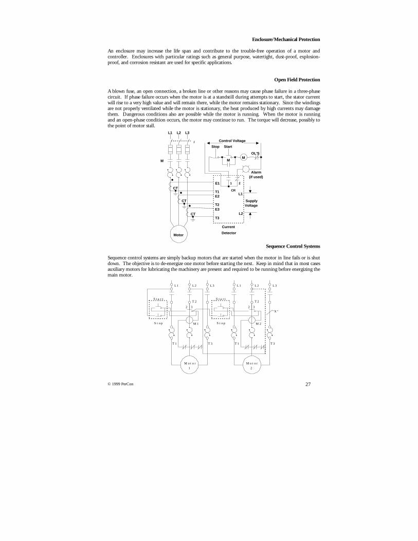
Open Field Protection
A blown fuse, an open connection, a broken line or other reasons may cause phase failure in a three-phasecircuit. If phase failure occurs when the motor is at a standstill during attempts to start, the stator currentwill rise to a very high value and will remain there, while the motor remains stationary. Since the windingsare not properly ventilated while the motor is stationary, the heat produced by high currents may damagethem. Dangerous conditions also are possible while the motor is running. When the motor is runningand an open-phase condition occurs, the motor may continue to run. The torque will decrease, possibly tothe point of motor stall.
Sequence Control Systems
Sequence control systems are simply backup motors that are started when the motor in line fails or is shutdown. The objective is to de-energize one motor before starting the next. Keep in mind that in most casesauxiliary motors for lubricating the machinery are present and required to be running before energizing themain motor.
Motor
1
Motor
2
Stop
Start
Stop
Start
L1 L2 L3 L1 L2 L3
T1 T1
T2 T2
T3 T3
2 3 32"X"
M1 M2
M MM
E1
T1E2
T2E3
T3
L1
L2
CT
SupplyVoltage
Control Voltage
Alarm(if used)
Stop Start
CR
1 2
Motor
Current
Detector
L1
i
L2 L3
CT
CT
OL'S
28 © 1999 PerCon
Reversed Phase Protection
If two phases of the supply of a three-phase induction motor are interchanged, the motor will reverse itsdirection of rotation. In elevator operation and industrial applications, this reversal can result in seriousdamage. Phase failure and phase reversal relays are safety devices used to protect motors, machines, andpersonnel from the hazards of open-phase or reversed-phase conditions.
Short Circuit Protection
For large motors greater than fractional horsepower ratings, short circuit and ground fault protectiongenerally is installed in the same enclosure as the motor disconnecting means. Over-current devices areused to protect the motor branch circuit conductors, the motor control apparatus, and the motor itselfagainst sustained over-current due to short circuits and grounds, and prolonged and excessive startingcurrents.
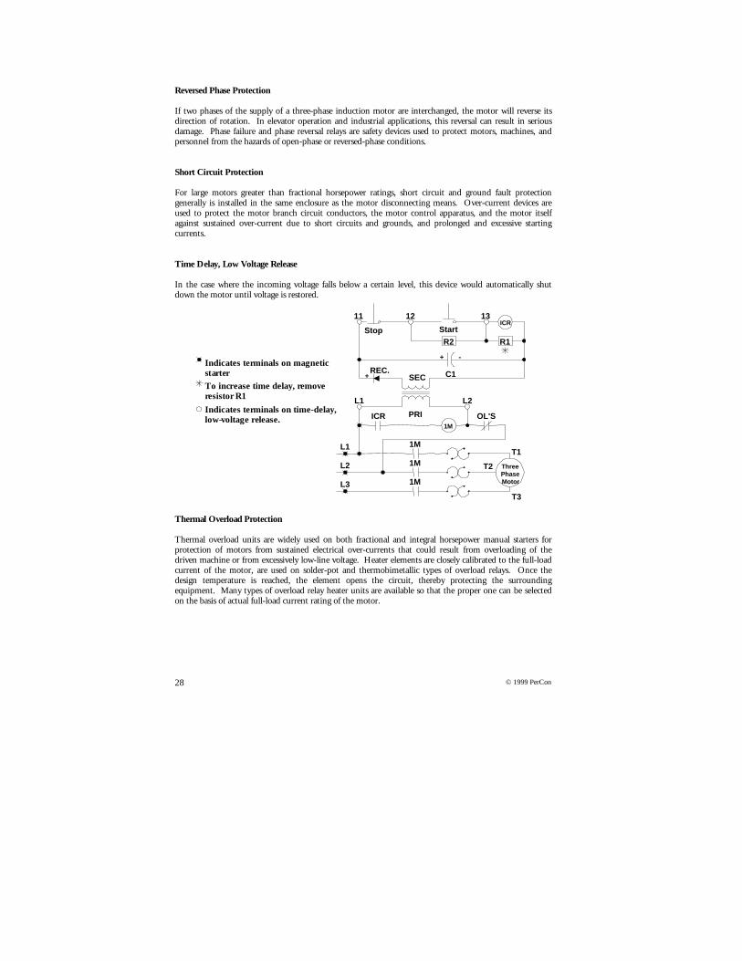
Time Delay, Low Voltage Release
In the case where the incoming voltage falls below a certain level, this device would automatically shutdown the motor until voltage is restored.
Thermal Overload Protection
Thermal overload units are widely used on both fractional and integral horsepower manual starters forprotection of motors from sustained electrical over-currents that could result from overloading of thedriven machine or from excessively low-line voltage. Heater elements are closely calibrated to the full-loadcurrent of the motor, are used on solder-pot and thermobimetallic types of overload relays. Once thedesign temperature is reached, the element opens the circuit, thereby protecting the surroundingequipment. Many types of overload relay heater units are available so that the proper one can be selectedon the basis of actual full-load current rating of the motor.
Stop Start
ICR
1M
OL'S
1M
1M
1M
ICR
R1R2
1312
L2
L2
L1
L3
L1
11
ThreePhaseMotor
T1
T3
T2
SEC
PRI
REC.+
+ -
C1Indicates terminals on magneticstarter
To increase time delay, removeresistor R1
Indicates terminals on time-delay,low-voltage release.
29© 1999 PerCon
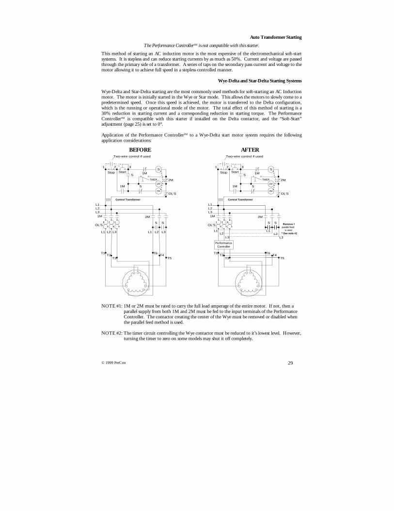
Auto Transformer Starting
The Performance ControllerSM is not compatible with this starter.
This method of starting an AC induction motor is the most expensive of the electromechanical soft-startsystems. It is stepless and can reduce starting currents by as much as 50%. Current and voltage are passedthrough the primary side of a transformer. A series of taps on the secondary pass current and voltage to themotor allowing it to achieve full speed in a stepless controlled manner.
Wye-Delta and Star-Delta Starting Systems
Wye-Delta and Star-Delta starting are the most commonly used methods for soft-starting an AC Inductionmotor. The motor is initially started in the Wye or Star mode. This allows the motors to slowly come to apredetermined speed. Once this speed is achieved, the motor is transferred to the Delta configuration,which is the running or operational mode of the motor. The total effect of this method of starting is a30% reduction in starting current and a corresponding reduction in starting torque. The PerformanceControllerSM is compatible with this starter if installed on the Delta contactor, and the “Soft-Start”adjustment (page 25) is set to 0°.
Application of the Performance ControllerSM to a Wye-Delta start motor system requires the followingapplication considerations:
BEFORE AFTER
NOTE #1: 1M or 2M must be rated to carry the full load amperage of the entire motor. If not, then a parallel supply from both 1M and 2M must be fed to the input terminals of the Performance Controller. The contactor creating the center of the Wye must be removed or disabled when the parallel feed method is used.
NOTE #2: The timer circuit controlling the Wye contactor must be reduced to it’s lowest level. However, turning the timer to zero on some models may shut it off completely.
T1T2
T3
OL'S
L1
1M 2M
T6
T5
S S
L2L3
T4
L1 L2 L3 L1 L2 L3
T1T2
T3
OL'S
L1
1M 2M
T6
T5
S S
L2L3
T4
L1L2
L3
L1L2
L3* See note #1
PerformanceController
Remove ifparallel feed
is used
1M
StartStop 1M
2M
S1M
S
OL'S
2M
S
1 2 3
Two-wire control if used
TIMER
Control Transformer
1M
StartStop 1M
2M
S1M
S
OL'S
2M
S
1 2 3
Two-wire control if used
TIMER
Control Transformer
30 © 1999 PerCon
Determine how the control system is powered. In some cases, power for control and safety systems isderived from the primary side of the contactor. If this is the case, the Wye-Delta contactor must bemounted between the Performance ControllerSM and the motor. This is the only case where this has to bedone.
The control and safety systems need to be re-powered from the primary of the Performance ControllerSM.If you are going to apply a Performance ControllerSM to a Wye-Delta, you must first fax a one-line diagramto Performance Control. If you attempt this process without technical assistance you will void thewarranty.
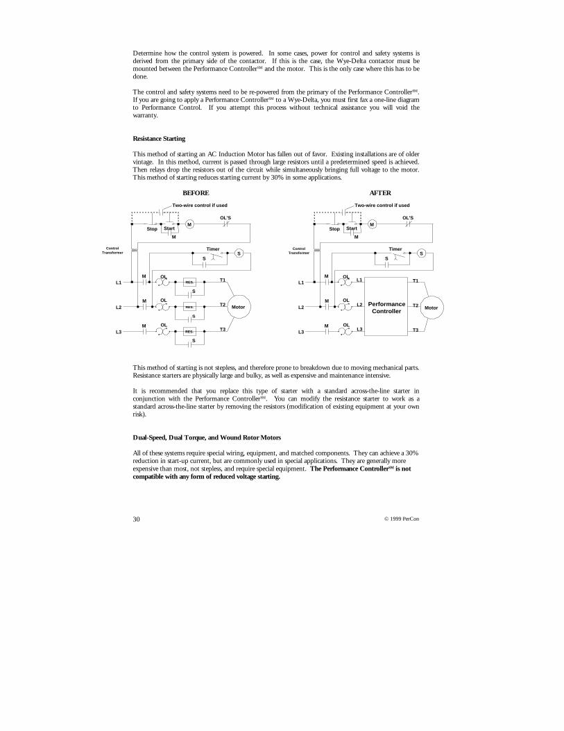
Resistance Starting
This method of starting an AC Induction Motor has fallen out of favor. Existing installations are of oldervintage. In this method, current is passed through large resistors until a predetermined speed is achieved.Then relays drop the resistors out of the circuit while simultaneously bringing full voltage to the motor.This method of starting reduces starting current by 30% in some applications.
BEFORE AFTER
This method of starting is not stepless, and therefore prone to breakdown due to moving mechanical parts.Resistance starters are physically large and bulky, as well as expensive and maintenance intensive.
It is recommended that you replace this type of starter with a standard across-the-line starter inconjunction with the Performance ControllerSM. You can modify the resistance starter to work as astandard across-the-line starter by removing the resistors (modification of existing equipment at your ownrisk).
Dual-Speed, Dual Torque, and Wound Rotor Motors
All of these systems require special wiring, equipment, and matched components. They can achieve a 30%reduction in start-up current, but are commonly used in special applications. They are generally moreexpensive than most, not stepless, and require special equipment. The Performance ControllerSM is notcompatible with any form of reduced voltage starting.
Timer
Stop Start
S
RES.
RES.
RES.
S
MOL'S
L1
L2
L3
M
M
M
M
OL
OL
OL
T1
T2
T3
Motor
Two-wire control if used
S
S
S
Timer
Stop Start
SS
MOL'S
L1
L2
L3
M
M
M
M
OL
OL
OL
Two-wire control if used
ControlTransformer
L1
L2
L3
PerformanceController
T1
T2
T3
Motor
ControlTransformer
31© 1999 PerCon
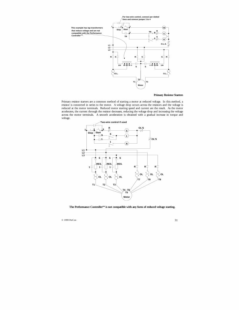
Primary Resistor Starters
Primary resistor starters are a common method of starting a motor at reduced voltage. In this method, aresistor is connected in series to the motor. A voltage drop occurs across the resistors and the voltage isreduced at the motor terminals. Reduced motor starting speed and current are the result. As the motoraccelerates, the current through the resistor decreases, reducing the voltage drop and increasing the voltageacross the motor terminals. A smooth acceleration is obtained with a gradual increase in torque andvoltage.
The Performance ControllerSM is not compatible with any form of reduced voltage starting.
TR
R
R S S RR S
S
TRStop Start
S
R
1 2 3
4 B
A
L1L2L3
T1T2
T3
O.L. O.L.
O.L.S.
Motor
100 10080 806565 50 500 0S S
For two-wire control, connect per dottedlines and remove jumper 3 to 4
TR
This example has tap transformers
that reduce voltage and are notcompatible with the PerformanceControllerS M .
Stop Start
1R
S S S
R RR1 1 1
L1L2L3
T1 T2 T3
T7 T8 T9
T4T5
T6
1
SS
OL'S
OL'SR1 2 3
S
1
OLOL OLOLOLOL
Two-wire control if used
Motor
RES.RES.RES.

32 © 1999 PerCon
Conclusions
As you can see many motor starting options are available to the end user. Each method offers benefits anddrawbacks. Across-the-line starting is the lowest initial cost method of starting an AC Induction Motor. Itis also the worst method of starting, as it puts the greatest strain on the system both electrically andmechanically. The end result is extremely high maintenance costs, as well as having the highest incidenceof motor and system failure.
Other methods of starting reduce inrush current but do not eliminate maintenance and breakdown. Initialcosts are high in each case with the autotransformer being the most expensive and the best of thesemethods.
None of the existing methods can match the Performance Controller’sSM features for simplicity andpayback for energy savings.

33© 1999 PerCon
Warranty
Seller warrants to Purchaser that any products provided by Seller hereunder are free from defects inmaterial and/or workmanship under normal use and operation during the warranty period stated herein.If any products provided hereunder prove to be defective in material and/or workmanship within eighteenmonths from date of sale, provided conditions of operation have been normal at all times, and that theproduct has not been subjected to abnormal stresses, including but not limited to, such causes as incorrectprimary voltage and frequency or improper ventilation, nor will this Warranty be extended to any productwhich has been subject to misuse, negligence, accident, improper installation or operation, nor does itextend to any product which has been repaired or altered by any party other than the Seller. Seller, ifpromptly notified thereof in writing, will correct such defect at Seller’s own expense, at Seller’s option,repairing or replacing the defective products.
Claims for defective products shall be subject to verification by an authorized employee of the Seller.
No products shall be returned to Seller without prior written consent. Products, which Seller consents tohave returned, shall be shipped prepaid F.O.B. Seller’s factory, or other location designated by Seller.Seller shall not assume responsibility or accept invoices for unauthorized repairs or alterations to itsproducts, even though defective. Any replacement or repaired product furnished under this Warranty shallbe warranted by Seller for the balance of the Warranty period and under the same Warranty conditions asapplicable to the original product.
The foregoing Warranty does not apply to experimental, prototype or developmental products.
Seller makes no warranty on products manufactured by others, which are resold by Seller. Seller shall useits best efforts to obtain from each such product manufacturer, in accordance with the manufacturer’swarranty or customary practice, the repair or replacement of products, which prove defective in materialand/or workmanship.
The foregoing Warranties shall apply to controllers, who are repaired by the Seller, except that theWarranty is limited to that portion of the product that was repaired or replaced. This Warranty is in lieuof any other right or remedies. In no event shall the Seller be liable for any special indirect consequentialor incidental damages.
Seller shall pay transportation charges for controllers returned to Seller and delivered to Buyer only if Selleris responsible under the terms of this Warranty. Buyer shall notify Seller, in writing, of any intention toreturn an allegedly defective product. Buyer shall give such advance notification to allow Seller to arrangefor shipment, should Seller so desire.
IN NO EVENT SHALL SELLER OR ITS SUPPLIERS BE LIABLE FOR ANY SPECIAL, INDIRECT, INCIDENTAL ORCONSEQUENTIAL DAMAGES INCLUDING, BUT NOT LIMITED TO LOSS OF PROFIT OR REVENUES, LOSS OFUSE OF THE PRODUCTS PROVIDED OR ANY ASSOCIATED PRODUCTS OR EQUIPMENT, COST OF CAPITAL,COST OF SUBSTITUTE PRODUCTS OR EQUIPMENT, FACILITIES, DOWNTIME EXPENSES, OR CLAIMS OFPURCHASER’S CUSTOMER FOR SUCH COSTS.
WARNING: Improperly installing and/or maintaining these products can result in death or serious personal injury. Beforeattempting installation or maintenance, read and understand all instructional materials related to the product. This Warranty ispublished solely for information purposes and should not be considered all-inclusive. If further information is required, you shouldconsult Performance Control, L.L.C. at (734) 975-9111.