Embed Size (px)
Citation preview

8/4/2011
1
Welcome to
Electric
Machines &
Drives
thomasblairpe.com/EMD
Thomas Blair, P.E. USF Polytechnic – Engineering
Session 9:
Motor Control &
Power Electronics
Fall 2011 Electric Machines and Drives
Thomas Blair, P.E. ([email protected])
Session 9
Chapter 20 – Basics of Industrical Motor Control
Chapter 21 – Fundamental Elements of Power Electronics (Part 1)
Electric Machines and Drives Thomas Blair, P.E.
Chapter 20 – Basics of Industrial Motor Control
Electric Machines and Drives Thomas Blair, P.E.
Chapter 20
Starting, stopping, direction
Speed, Torque, Power – chapter 22/23
Size accordingly
Switches, breakers, Push Button, relays,
contactors (starters), fuses, OL, Lights
(annunciator), resistors, inductors, xfmrs,
capacitors.
Symbols in Table 20A
4
Electric Machines and Drives Thomas Blair, P.E.
Chapter 20
Electric Machines and Drives Thomas Blair, P.E.
Chapter 20
8/4/2011
2
Electric Machines and Drives Thomas Blair, P.E.
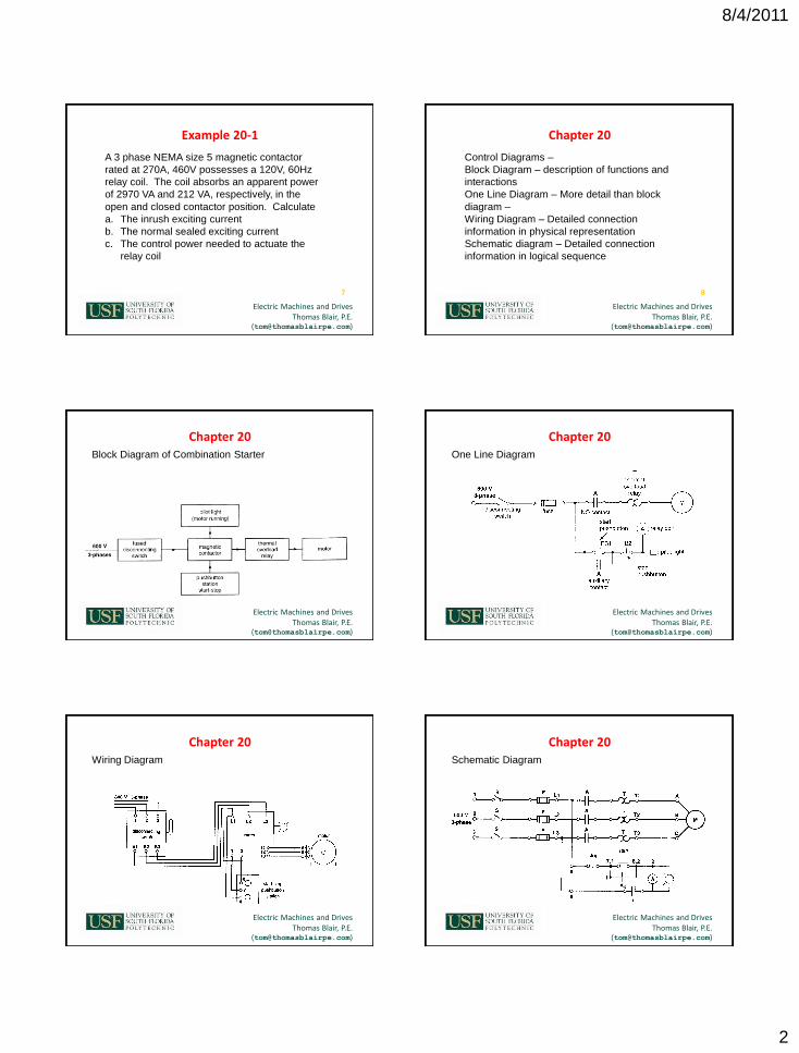
Example 20-1
A 3 phase NEMA size 5 magnetic contactor
rated at 270A, 460V possesses a 120V, 60Hz
relay coil. The coil absorbs an apparent power
of 2970 VA and 212 VA, respectively, in the
open and closed contactor position. Calculate
a. The inrush exciting current
b. The normal sealed exciting current
c. The control power needed to actuate the
relay coil
7
Electric Machines and Drives Thomas Blair, P.E.
Chapter 20
Control Diagrams –
Block Diagram – description of functions and
interactions
One Line Diagram – More detail than block
diagram –
Wiring Diagram – Detailed connection
information in physical representation
Schematic diagram – Detailed connection
information in logical sequence
8
Electric Machines and Drives Thomas Blair, P.E.
Block Diagram of Combination Starter
Chapter 20
Electric Machines and Drives Thomas Blair, P.E.
One Line Diagram
Chapter 20
Electric Machines and Drives Thomas Blair, P.E.
Wiring Diagram
Chapter 20
Electric Machines and Drives Thomas Blair, P.E.
Schematic Diagram
Chapter 20

8/4/2011
3
Electric Machines and Drives Thomas Blair, P.E.
ATL start – Simple, Large inrush, Large Torque
Starter = Contactor + OL
Combination starter = Starter + Switch (or CB)
Purpose of OL vs Purpose of fuse?
Chapter 20
Electric Machines and Drives Thomas Blair, P.E.
Chapter 20
Higher voltage starters – CPT – reduce control
voltage
Manual ATL starter vs Magnetic ATL starter?
Simplicity
Safety
14
Electric Machines and Drives Thomas Blair, P.E.
Chapter 20
OL curve –
From cold condition
Reduce about 30% if from hot condition
Class 10 – @ 6X PU, trips in 10 sec from cold
condition
Class 20 – @ 6X PU, trips in 20 sec from cold
condition
Class 30 – @ 6X PU, trips in 30 sec from cold
condition
NEC requirements, conductor size, fuse size,
etc 15
Electric Machines and Drives Thomas Blair, P.E.
Overload Curve
Chapter 20
Electric Machines and Drives Thomas Blair, P.E.
Inching / Jogging
Severe contact duty –make/break currents
Contactor oversized
Chapter 20
Electric Machines and Drives Thomas Blair, P.E.
Reversing – change 2 lines
Mechanical / electrical interlocks
E-stop example
Chapter 20

8/4/2011
4
Electric Machines and Drives Thomas Blair, P.E.
Plugging – Stop Motor
Chapter 20
Electric Machines and Drives Thomas Blair, P.E.
Zero Speed Switch –
PM drags cup in direction of rotation
Chapter 20
Electric Machines and Drives Thomas Blair, P.E.
Reduced Voltage Starting (softstart)
Primary Resistance
Primary Reactance
Wye – Delta
Auto Xfmr
Partial winding start
Solid state
Chapter 20
Electric Machines and Drives Thomas Blair, P.E.
Control circuit for primary resistance start
T typically on common return
Larger size contactors use circuit C for inrush Torque Q voltage2
Chapter 20
Electric Machines and Drives Thomas Blair, P.E.
Torque Q voltage2
Current Q voltage
Chapter 20
Electric Machines and Drives Thomas Blair, P.E.
Example 20-2
A 150 kW (200HP), 460V, 3 phase, 3520 rpm, 60 Hz
induction motor has a locked rotor torque of 600 Nm and
a locked rotor current of 1400 A. Three resistor are
connected in series with the line so as to reduce the
voltage across the motor to 0.65 pu. Calculate
a. The apparent power absorbed by the motor under
full voltage, locked rotor conditions
b. The apparent power absorbed y the motor when the
resistors are in the circuit.
c. The apparent power drawn from the line, with the
resistor in the circuit
d. The locked rotor torque developed by the motor
24
8/4/2011
5
Electric Machines and Drives Thomas Blair, P.E.
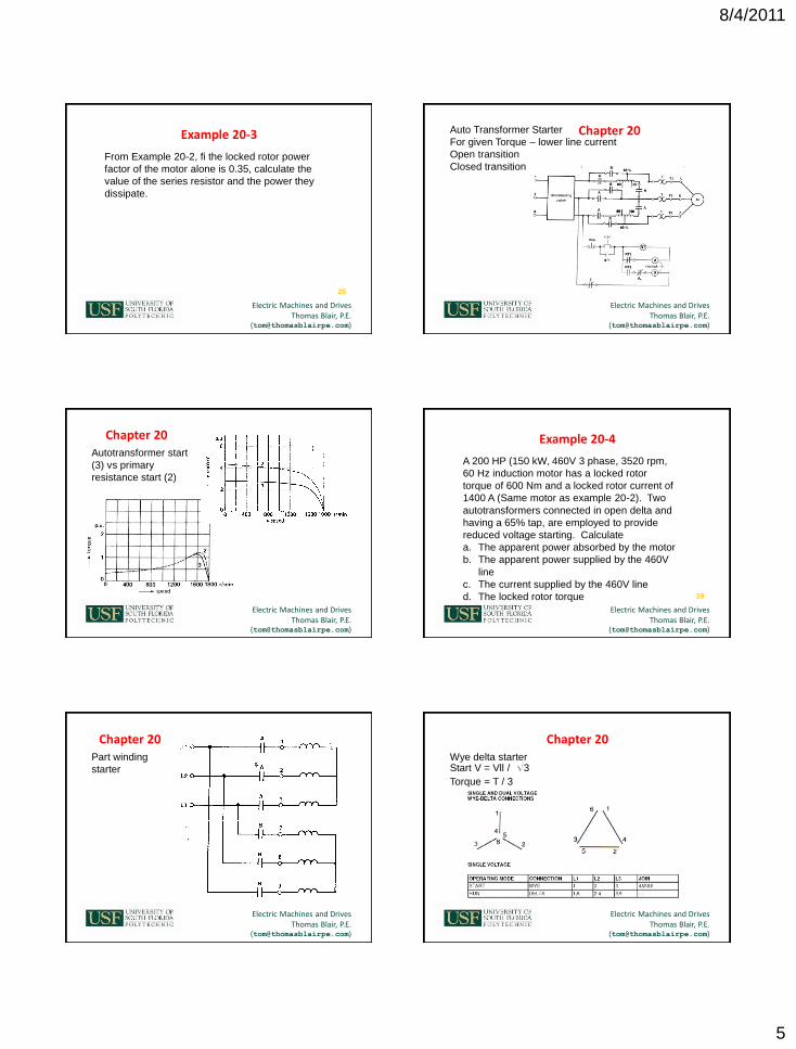
Example 20-3
From Example 20-2, fi the locked rotor power
factor of the motor alone is 0.35, calculate the
value of the series resistor and the power they
dissipate.
25
Electric Machines and Drives Thomas Blair, P.E.
Auto Transformer Starter
For given Torque – lower line current
Open transition
Closed transition
Chapter 20
Electric Machines and Drives Thomas Blair, P.E.
Autotransformer start
(3) vs primary
resistance start (2)
Chapter 20
Electric Machines and Drives Thomas Blair, P.E.
Example 20-4
A 200 HP (150 kW, 460V 3 phase, 3520 rpm,
60 Hz induction motor has a locked rotor
torque of 600 Nm and a locked rotor current of
1400 A (Same motor as example 20-2). Two
autotransformers connected in open delta and
having a 65% tap, are employed to provide
reduced voltage starting. Calculate
a. The apparent power absorbed by the motor
b. The apparent power supplied by the 460V
line
c. The current supplied by the 460V line
d. The locked rotor torque 28
Electric Machines and Drives Thomas Blair, P.E.
Part winding
starter
Chapter 20
Electric Machines and Drives Thomas Blair, P.E.
Wye delta starter Start V = Vll / S3
Torque = T / 3
Chapter 20

8/4/2011
6
Electric Machines and Drives Thomas Blair, P.E.
Drive
Fundamentals –
4 quadrants of
operation
More info in
Chapters 20 - 22
Chapter 20
Electric Machines and Drives Thomas Blair, P.E.
Motor – Generator - Brake
Chapter 20
Electric Machines and Drives Thomas Blair, P.E.
Torque / speed curve AC induction machine
Chapter 20
Electric Machines and Drives Thomas Blair, P.E.
Varying Volts and Hertz on AC machines
Chapter 20
Electric Machines and Drives Thomas Blair, P.E.
DC effect on Torque
speed curve
Chapter 20
Electric Machines and Drives Thomas Blair, P.E.
Examle 20-5
A standard 3 phase, 10 HP, 575V, 1750 rpm,
60 Hz, NEMA class D squirrel cage induction
motor develops a torque of 110 Nm at a speed
of 1440 rpm. If the motor is excited at a
frequency of 25 Hz, calculate the following:
a. The required voltage to maintain the same
flux in the machine
b. The new speed at a torque of 110 Nm
36

8/4/2011
7
Electric Machines and Drives Thomas Blair, P.E.
Current vs Speed
Chapter 20
Electric Machines and Drives Thomas Blair, P.E.
Example 20-6
Using the information revealed by the 60Hz
torque speed and current speed curves of
figure 20.42, calculate the voltage and
frequency required so that the machine will run
at 3200 rpm while developing a torque of 100
Nm. What is the corresponding stator current?
38
Electric Machines and Drives Thomas Blair, P.E.
If freq changed
F 60hz -> 30 hz
Motor speed still
1650RPM
1 – 2 – 3 – 4
Final motor speed
750
Note slip still 150 RPM
for same torque
Chapter 20
Electric Machines and Drives Thomas Blair, P.E.
Chapter 21 – Fundamental Elements of Power Electronics (Part 1)
Electric Machines and Drives Thomas Blair, P.E.
Chapter 21
Power Electronics -> control of electric
machine parameters such as Torque, Speed,
Power.
Due to importance, deserves some study of
subject for EMD.
41
Electric Machines and Drives Thomas Blair, P.E.
Chapter 21
V34 = I * R Switch open – V12 K 0
Switch closed – V12 = 0
V78 = 1/C f Ic * dt V56 = L * di/dt

8/4/2011
8
Electric Machines and Drives Thomas Blair, P.E.
Diode Behavior
Vak = 0 -> open
Vak < 0 -> open
Vak > 0 -> short
I > Ihold -> short
I < Ihold -> open
PIV ->
Iav(max) -> max avg I
T(max) -> max Temp
Max di/dt (turnon)
Max dv/dt (turnoff)
Chapter 21
Electric Machines and Drives Thomas Blair, P.E.
Resistive Battery Charger
I2R losses in resistor
I = E43/R
Chapter 21
Electric Machines and Drives Thomas Blair, P.E.
Inductive Battery Charger
Stored Energy example
Imax = A(+)/L
Chapter 21
Electric Machines and Drives Thomas Blair, P.E.
The coil below has an inductance of 3.3 mH and the
battery voltage is 60V. Calculate the peak current if
the line frequency is 60 Hz.
Example 21-1
Electric Machines and Drives Thomas Blair, P.E.
Chapter 21
Single Phase Bridge Rectifier
2 pulse rectifier
Fripple = #pulse*fline
= 2 * fline
Ripple = 2*f(line)
Ripplep-p = Epeak
Ed = 0.9 E Id = Ed/R = 0.9 E / R
Ed = dc voltage of single phase bridge rectifier (V)
E = effective value of ac line voltage (V)
47
Electric Machines and Drives Thomas Blair, P.E.
Single phase rectifier
Chapter 21

8/4/2011
9
Electric Machines and Drives Thomas Blair, P.E.
Example 21-2
The ac source in fig 21.13a has an effective
voltage of 120V, 60Hz. The load draws a dc
current of 20A. Calculate
a. The dc voltage across the load
b. The average dc current in each diode
49
Electric Machines and Drives Thomas Blair, P.E.
Filters –
L – constant current
Series w/ load
Line current square
wave
C – constant voltage
Parallel w/ load
Line current spike
a. Rectifier with
inductive filter
b. Rectifier with cap
filter
Chapter 21
Electric Machines and Drives Thomas Blair, P.E.
L – constant current - Series
C – constant voltage - Parallel
Voltage and current waveforms in inductive filter
Chapter 21
Electric Machines and Drives Thomas Blair, P.E.
Chapter 21
Ripple in single phase rectifier with filter
Ripple = (5.5 P) / (f Wl)
Ripple = peak to peak current as % of dc
current (%)
Wl = dc energy stored in the smoothing
inductor (J)
P = dc power drawn by the load (W)
f = frequency of the source
52
Electric Machines and Drives Thomas Blair, P.E.
Example 21-3
We wish to build a 135V, 20A dc power supply
using a single phase bridge rectifier and an
inductive filter. The peak to peak current ripple
should be about 10%. If a 60 Hz ac source is
available, calculate the following;
a. The effective value of the ac supply voltage
b. The energy stored in the inductor
c. The inductance of the inductor
d. The peak to peak current ripple
53
Electric Machines and Drives Thomas Blair, P.E.
3 phase, 3 pule
rectifier
Chapter 21

8/4/2011
10
Electric Machines and Drives Thomas Blair, P.E.
3 pulses per cycle – Filter element L
Conduction period 360O / 3 pulses = 120O per pulse
Chapter 21
Electric Machines and Drives Thomas Blair, P.E.
Chapter 21
Commutation – change of diode state from on
to off
Natural or Line commutation – Line voltage
forces commutation
Ripple voltage less than single phase
Fripple = #pulse*fline = 3 * fline
Ed = 0.675 E
Ed = average or dc voltage of a 3 pulse
recitifer (V)
E = effective ac line voltage (V) 56
Electric Machines and Drives Thomas Blair, P.E.
Chapter 21
3 Phase, 6 pulse rectifier – 1.225 < Ed < 1.414
Peak to Peak 1.414 – 1.225 = 0.189 E
Fripple = Fline * Pulse #
Fripple = Fline * 6
Ed = 1.35 E
Ed = dc voltage of 6 pulse rectifier (V)
E = effective line voltage (V)
57
Electric Machines and Drives Thomas Blair, P.E.
3 phase, 6 pulse rectifier
Chapter 21
Electric Machines and Drives Thomas Blair, P.E.
Chapter 21
Ripple - PIV = Epeak
Conduction 360O / #pulse = 360O/6 = 60Oe
Ripple = (0.17 P) / (f Wl)
Ripple = peak to peak current as % of the dc
current (%)
Wl = dc energy stored in the inductor (J)
P = dc power drawn by the load (W)
f = frequency of the 3 phase, 6 pulse source )
59
Electric Machines and Drives Thomas Blair, P.E.
Voltage and current waveforms
Chapter 21

8/4/2011
11
Electric Machines and Drives Thomas Blair, P.E.
Chapter 21
Electric Machines and Drives Thomas Blair, P.E.
6 pulses
Chapter 21
Electric Machines and Drives Thomas Blair, P.E.
Example 21-4
A 3 phase bridge rectifier has to supply power
to a 360 kW, 240V dc load. If the 600V, 3
phase, 60 Hz feeder is available, calculate the
following
a. Voltage rating of the 3 phase transformer
b. DC current per diode
c. PIV across each diode
d. Peak to peak ripple in the output voltage
and its frequency
63
Electric Machines and Drives Thomas Blair, P.E.
Chapter 21
a. Calculate the inductance of the smoothing
choke required in example 21-4 if the peak
to peak ripple in the current is not to
exceed 5%.
b. Does the presence of the choke modify the
peak to peak ripple in the output votlage
Eka?
64
Electric Machines and Drives Thomas Blair, P.E.
Chapter 21
Relationship between Id and Iline
I = S(120/180) Id = 0.816 Id
Pd = Ed Id Pac = S3 E If
If = 0.78 Id = 0.955 I
I is effective value of line current
If is fundamental value of line current
65
Electric Machines and Drives Thomas Blair, P.E.
Chapter 21
Total PF = PF Displacement & PF Distortion
PF = active power/apparent power
PF dist = If/I but If = 0.955 I
PF dist = 95.5% due to line current being
rectangular
66

8/4/2011
12
Electric Machines and Drives Thomas Blair, P.E.
Chapter 21
Total PF = PF Displacement & PF Distortion
Total PF = P / (E IL)
Displacement PF = P / (E If)
P = active power per phase (W)
E = effective value of voltage per phase (V)
IL = effective value of line current including
fundamental and harmonics (A)
If = effective value of the fundamental
component of line current (A)
67
Electric Machines and Drives Thomas Blair, P.E.
Chapter 21
Harmonic Content and THD
N +/- 1
Amplitude = IF Amplitude / harmonic number
I2 = IF2 + IH
2
IH2 = IHA
2 + IHB2 + IHC
2 + IHD2 +…
THD = IH / IF
I = rms value of the line current
IF = rms value of the fundamental component
of line current
IH = rms value of all the harmonic components
combined. 68
Electric Machines and Drives Thomas Blair, P.E.
Harmonic Content and delay angle
Chapter 21
Electric Machines and Drives Thomas Blair, P.E.
Example 21-6
The 3 phase, 6 pulse rectifier in figure 21.19
furnishes a dc current of 400A to the load.
Estimate, for line 1
a. The effective value of the line current
measured by an rms hook on ammeter
b. The effective value of the fundamental
component of line current
c. The peak value of the 7th harmonic
d. The rms value of the 7th and 11th harmonics
combined.
70
Electric Machines and Drives Thomas Blair, P.E.
Solid state switch –
point of conduction
controlled
a.Anode positive
b.Gate current injected
c.Anode to cathode
current remain positive
Chapter 21
Electric Machines and Drives Thomas Blair, P.E.
Vg = (+)
NPN pulling the N substrate low
PNP is gated
Current to flow from cathode to gate
Chapter 21

8/4/2011
13
Electric Machines and Drives Thomas Blair, P.E.
Construction of “hockey puck”
Chapter 21
Electric Machines and Drives Thomas Blair, P.E.
Packaging:
Chapter 21
Electric Machines and Drives Thomas Blair, P.E.
Steady state
model
Goal =
Minimize Tj
Chapter 21
Electric Machines and Drives Thomas Blair, P.E.
Tj(max) = 125C
HS Thermostat = 90C
Chapter 21
Electric Machines and Drives Thomas Blair, P.E.
Ploss = Vak * I
* # phases
Data sheet = P
* # devices
Chapter 21
Electric Machines and Drives Thomas Blair, P.E.
SCR Critical Ratings:
PIV = Peak Inverse Voltage
RMS = Current rating (at Tj)
Di/dt = Rate of change of current
Qrr = Peak reverse recovery charge
Chapter 21

8/4/2011
14
Electric Machines and Drives Thomas Blair, P.E.
Chapter 21
Typical PIV ratings
79
Vrms PIV
120 300
208 12:00 AM
240 600
380 1000
415 1000
440 1200
480 1200
575 1600
2300 6000
4160 12000
6600 18000
7200 18000
13800 36000
Electric Machines and Drives Thomas Blair, P.E.
!!!SAFETY!!!
SCR output =
input voltage
Chapter 21
Electric Machines and Drives Thomas Blair, P.E.
Two Types of control
Chapter 21
Electric Machines and Drives Thomas Blair, P.E.
Chapter 21
Applications of control
82
ELEMENT TYPE HOT / COLD RATIO CONTROL TYPE
Molybdenum 15:01 Phase
Tungsten 20:1 Phase
Graphite 20:1 Phase
Nichrome 1.1:1 Zero
Tungsten 20:1 Phase
Iron Chromium 1.1:1 Zero
80/20 Nichrome 1.1:1 Zero
35/20 Nichrome 1.2:1 Zero
Silicon Carbide 0.8:1 Phase
Electric Machines and Drives Thomas Blair, P.E.
Chapter 21 next session Electric
Machines &
Drives
thomasblairpe.com/EMD
Thomas Blair, P.E. USF Polytechnic – Engineering
End of Session 9:
Motor Control &
Power Electronics
Spring 2011