Embed Size (px)
Citation preview
INDUCED POLARIZATION – THEORY AND INTERPRETATION OF WELL-LOGGING DATA
VYNUCENÁ POLARIZACE – TEORIE A INTERPRETACE KAROTÁŽNÍCH ÚDAJ�
František Ryšavý 1
AbstractThe method of induced polarization was originally considered like the method for prospecting of ores and anthracite only. It seems
that in the sedimentary basins where the rocks are saturated with fresh or brackish waters that method can be successfully used for prospecting of hydrocarbons as well. The registered factor of the mentioned method is the apparent chargeability of rocks. It is a dimensionless one. An influence of the borehole diameter acts indirectly, because there are used the reduced variables and the output factor is also reduced. It presents the real reduced chargeability of rocks. This factor is registered with the help of the potential array of electrodes.
Abstrakt Metoda vynucené polarizace byla p�vodn� pokládána jen za metodu pro vyhledávání rud a antracitu. Zdá se, že v sedimentárních
pánvích, kde jsou horniny nasyceny sladkou nebo brakickou vodou, m�že být tato metoda úsp�šn� použita i pro vyhledávání uhlovodík�.Registrovanou charakteristikou zmín�né metody je zdánlivá elektrická susceptibilita hornin. Je bezrozm�rná. Vliv pr�m�ru vrtu p�sobínep�ímo, nebo� se používají redukované prom�nné na pr�m�r vrtu; také výstupní faktor je redukován na pr�m�r vrtu. Ten p�edstavuje skute�nou susceptibilitu hornin, redukovanou na pr�m�r vrtu. Registrujeme ji pomocí potenciálového uspo�ádání elektrod.
Keywords induced polarization, chargeability, permittivity, the characteristic function, well-logging
Klí�ová slova vynucená polarizace, polarizovatelnost, permitivita, charakteristická funkce, karotáž
1 Introduction For electrical methods of well-logging there is made mostly the registration of electrical resistivity in various modifications. You can
register various electrode arrays having focused or non-focused electric fields; you can use direct or alternating currents. However, there exist the next electrical factors. The induced polarization registers the chargeability of rocks. It seems I can interpret, if I know the chargeability, the permittivity of rocks too, nevertheless, this way is not unambiguous due to very complicated relations being between both the above factors.
- 110 -
2 The physical units used The main factor of this is the above chargeability of rocks that is defined with relation:
,0 EP
UU
P
VPe �
���� (1)
where �e = the chargeability of rocks, UVP = the voltage created by the polarization field [mV], UP = the voltage of the outer polarizing field [mV], P = the vector of polarization [C×m-2], E = the intensity of the outer polarizing field [V×m-1], and
� 0 = the vacuum permittivity [F×m-1].Dimensionally for those units there hold the following relations: [� 0] = [F× m-1] = [m-3× kg-1× s4 × A2],[P] = [C× m-2] = [s × A × m-2], and [E] = [V× m-1] = [m × kg × s-3 × A-1].
The registered factor remarked as �e is dimensionless. It seems to be very attractive to interpret the permittivity with the help of the chargeability; however, just this is very complicated thing due to very different relations between chargeability and permittivity.
The rocks having low permittivity can use the relation being valid for an isotropic dielectric: ,1 �� er �� (2)
where �r = the permittivity of rocks. On the contrary, the rocks having middle and high permittivity are directed with Clausius-Mossotti equation:
.31
21
���
er
r �����
�
�� (3)
The mentioned equation characterizes non-polar fluids and gases like hydrocarbons are and, too, the two-atom cubic crystals. The values calculated according to relations (2) and (3) are different. This is probably why it is impossible unambiguously to
interpret the permittivity of rocks. And for polar materials and fluids like water is that is even more complicated.
3 Principles of registration Induced polarization I can register either with direct current, or with alternating current. When I have direct current, I register in the
time domain. I compare two voltages. The first is the voltage of current transmitting and the second is the voltage decay when the current is
- 111 -
suspended. I can register spectrally, i.e., registration of voltages in two and more the time windows, or integrally, then I register all extent of voltage decay over all time base. What is characteristic is the voltage decay has an exponential shape.
The second and more used one is to register in the frequency domain. Here I use an alternating current. In this case it is possible to register resistivity and induced polarization simultaneously. We observe various curves of resistivity registered with different frequencies. The induced polarization is interpreted like changes of resistivity with the change of frequency. This second way is more frequent, because offers great possibilities of depiction, we have 2 and 3D- coloured borehole sections either for resistivity and induced polarization. It is excellent for qualitative interpretation when I have to locate the place and position of ore bodies, or possibly an extent a position of contamination. This domain of qualitative interpretation is well investigated. They are authors like LUO, Y., and ZANG, G. (1998), CAHYNA, F., MAZAC, O., and VENDHODOVA, D. (1990) and namely ZHDANOV, M. S. (2006). The last one presents all new theory important for quantitative interpretation of induced polarization; the rock is formed by non-conductive matrix and disseminated conductive grains having spherical and ellipsoidal shapes. It is, however, to say, that this model of medium is determined for interpretation of disseminated ore in the rock. From Czech authors I should like to remember the text-book “Geoelectric methods of exploration”, KAROUS, M. (1989). There is very in detail described the frequency method, its theoretical analyse and modelling of various geometricbodies.
It seems that for quantitative interpretation such things like permeability of sedimentary rocks, prospecting of hydrocarbons insediments saturated by salt/fresh water and study of influence of various technical and geological factors on registration are the time domain will be more useful than the frequency one. The pulse method is commonly used. Here are too important authors having studythose problems. I can remember such ones like DACHNOV, V.N. (1967), DOBRYNIN, V.M. (1988), and SEIGEL, H. O. (1970) are. From Czech authors I have again to name the text-book of KAROUS, M. (1989). There is well described theory of the pulse method.Author in detail studied theoretically registering not only in the domain of discharging curve, but too in the domain of charging curve. It seems that his conclusions in the recent time are confirmed. In spite of all activities done in the time domain it seems that ways of quantitative interpretation are not exhausted yet. It is about spectral and integral interpretation either in the above domain. The aim of this paper is to offer the detailed description and explanation of influence various technical and geological factors on registering induced polarization, further, an explanation how to evaluate permeability of sediments with the help of effective porosity which is interpretable due to well-logging records for induced polarization and total porosity. This all is thing of integral registration and interpretation; the spectral registration in the time domain has wide possibilities of interpretation for mud, invasion zone and non-invasion zone.
4 The rocks and types of their polarization This method using the induced polarization for sedimentary rocks is well-presented by fine-grained sands and sandstones; even more
it holds for shales and aleurits. Those rocks have outstanding deflections. On the contrary, the coarse-grained and the middle-grained sands have low deflections. The lowest deflection is for gypsum. There are well observed the seams of anthracite and sulfitic ores as pyrite.
- 112 -
Carbonates belong to the rocks having lower deflections, nevertheless, the porous badly-consolidated limestones or dolomites arecharacterized with significantly low deflections than those compact well-consolidated as marbles are. Volcanic and metamorphic rocks without ore minerals have very low deflections too.
Here come through physical-chemical polarization effects of mineralized metallic particles of the rock material and/or the electro-kinetic effects in the pores of reservoirs. LUO, Y., and ZANG, G. (1998), SEIGEL, H. O. (1970).
There exist two main types of polarization. The first is the shifting polarization. It is for non-polar materials, fluids and gases. Owing to the outer electric field the ions or electrons chaotically dispersed are shifted into direction of the outer field. Up to now the neutral electrical particles will have formed electrical dipoles. The electrically-neutral material has then its own electric field.
For ion-shifting polarization it is characteristic that the polarization potentials create on the boundary of electrolyte and the rock matrix. Due to outer electric field the double electrical layer being on the surface of grains is deformed. Sometimes you can observe clusters of ions directly in the capillary pores of rock there. The positive ions shift in the direction of action of the outer electric field, whereas, the negative ions shift in the contrary direction. This type of polarization is typical for the bound-water by surface of grains.
The conductive materials like black coal, anthracite, metallic sulphides (except sphalerite) and iron ores are, have, as well, theelectron-shifting polarization. In that case there are shifted not ions, but electrons. Such polarization is realized not on the surface of matrix, but inside of the matrix.
You can observe also polarisation of fluids being in the pores of rocks. We distinguish those fluids in two main groups: the polar ones and the non-polar ones. The non-polar fluids have the shifting polarization and there belong just hydrocarbons there. On the contrary to them the formation water is the polar fluid which has the dipole polarization. This polarization being dependent on temperature is characteristic for the free-formation water.
The last mentioned type of polarization - it is the second main type. Thanks to outer electric field in the free-formation water there are forced into line fields of chaotically dispersed dipoles. Thus, free-formation water forms its own polarization potentials. In the nature surroundings the most of rocks have both main polarizations. It depends on quantum of factors like chemical composition, moisture of rocks and next ones are.
For well-logging it is very important that the shifting polarization is independent on temperature, whereas, the dipole polarization has reversed relationship on temperature. Because of the temperature increasing with the borehole depth contribution of the dipole polarization will be lower and lower. It means that an influence of the free-formation water will be lower and lower too.
5 The physical factors registered For induced polarization there is used the direct stabilized current working in pulse mode in the time domain. The current must be
strong enough. You can register two factors: the chargeability of rocks and the relaxation time of the polarization field.
- 113 -

Registration is made simultaneously, however, the relaxation time is registered as the time spectrum and it can present problemswhen equipment has not enough wide of the time base. Then observations can be done only as a static registration. Registration for the single depth points is in various time windows. Such registration takes long time and presents tens and hundreds of milliseconds.
The time domain being close connected with evaluation of the time spectrum is not so well investigated like the frequency domainthat offers easier and wider results for 2d-colour depiction or 3d-depiction, however, for quantitative interpretation collector properties of sedimentary rocks has ways to new information. It is not only about interpretation of the time spectrum, but too about integral registration of signal over all time bases. Here goes way to interpretation of effective porosity and later on permeability of rocks.
6 The secondary factors affecting the chargeability of rocks The chargeability of rocks remarked as �e is affected with these important factors:
Chemical composition of the rock matrix. If the rock has also ore minerals, it needs to consider the electron displacement polarization, too. When the rock has no such
minerals, its chargeability will be low. The specific surface of the matrix grains.
If the specific surface of grains is increasing, the chargeability of rocks is increasing too; however, the permeability of rocks is decreasing. This fact can explain those big deflections for shales and aleurits, the lower deflections for fine-grained sand and sandstones and, finally, very low deflections for coarse-grained sand and sandstones. The rock moisture.
This point is bound with the previous point. We distinguish two component of formation water: the free-water component and the bound-water component. The bigger the free-water component is the lower the bound-water component will be. Because the chargeabilityof rocks is oriented on the specific surface of rocks and this will be in such case lower too, due to the bound-water component, the chargeability of rocks will be falling down. Influence of formation water and its grade of mineralization.
There is observed that for Rw > 1 m the chargeability of rocks is proportionate to the formation water resistivity. In such case mineralization does not influence the chargeability. It holds for fresh and brackish waters. In this case we are able well to perform the beds holding hydrocarbons; differences between hydrocarbons and fresh water are well-visible. In the domain where it holds that Rw < 1 mthere is situation all different. Formation water becomes to be rather a conductor than the dielectric. The chargeability of water having been before high is falling down to zero. Differences between hydrocarbons and salt water are lower and lower thanks to increasing content of salt in the water. This domain is not convenient for prospecting of hydrocarbons.
- 114 -

The magnitude of the electric direct current DACHNOV, V.N (1967) published that for laboratory conditions there is recommended the density of current 0.5 – 20 A/ cm2. In
this interval the chargeability of anthracite and sulfitic ores is almost constant. On the contrary for sediments as sandstones and carbonates are you can observe that the chargeability is increasing!
However, well-logging methods need to have relatively high electric current – its density must be higher than 20 A/ cm2. In this domain the chargeability of anthracite and sulfitic ores is decreasing, whereas, sandstones and carbonates have constant values.
7 The factors influencing the relaxation time The registration of the relaxation time is based on registration of the time spectrum. If an electric pulse has been finished, there will
be registered voltage of the polarization field changing itself in the flowing time. We register the above voltage in various time windows. And here begin troubles. Relaxation of the polarization field is relatively long, it are tens or hundreds of milliseconds. If I register simultaneously, I will have to register in the relatively short-time windows, if the time base is not enough wide, and it presents I register only the contribution of mud. Therefore in case of deep invasion of mud filtrate I am to attempt to reach contributions of the long-time windows too. This can present to record discontinuous curve of well-logging data; I think by that to make registration in each point of the borehole depth.
The registered voltage is directed by the following relation:
� � ,exp01 �
��
���
���
�
� �� �
� � i
n
iiVP
tUU (4)
where �i = the relaxation time of the polarization field for i-th component of rock [s], Ui (0) = the value of voltage when it holds that t = 0 for i-th component of rock [mV], and UVP = the registered voltage in the selected time window [mV]. As you see, after formula (14) this case uses the pulse method having long pulse. Here can prove all types of polarization.
8 Relation between the apparent chargeability and the real chargeability of rocks I proceeded in the process of derivation in accordance with DACHNOV V.N, (1967), however, the procedure was enlarged by
studying an eccentricity of tool in the borehole and there are some next adjustments too there. The main proposition is that the distance between the current electrode A and the potential electrode M is very short. Such distance is the spacing of tool remarked as L and it holds that L << d, if d is the diameter of borehole.
- 115 -
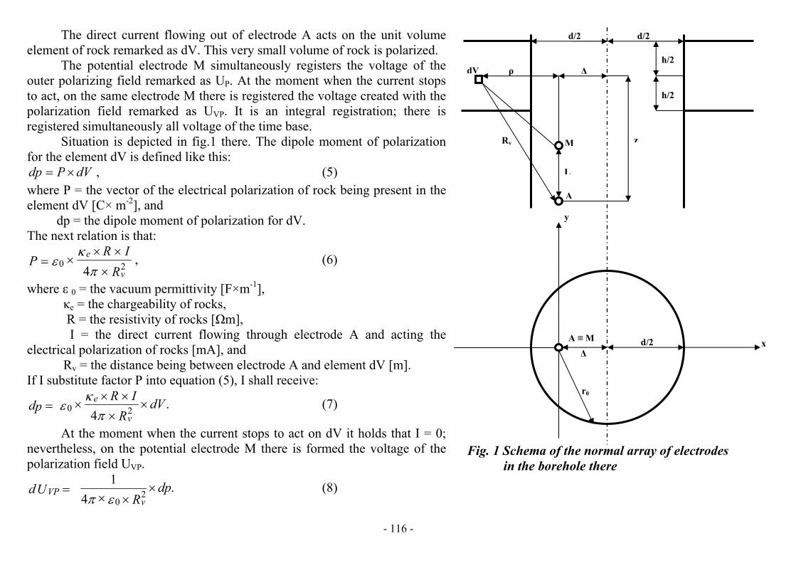
The direct current flowing out of electrode A acts on the unit volume element of rock remarked as dV. This very small volume of rock is polarized.
The potential electrode M simultaneously registers the voltage of the outer polarizing field remarked as UP. At the moment when the current stops to act, on the same electrode M there is registered the voltage created with the polarization field remarked as UVP. It is an integral registration; there is registered simultaneously all voltage of the time base.
Situation is depicted in fig.1 there. The dipole moment of polarization for the element dV is defined like this:
,dVPdp �� (5) where P = the vector of the electrical polarization of rock being present in the element dV [C× m-2], and dp = the dipole moment of polarization for dV. The next relation is that:
,4 20
RIR
Pv
e
�
����
��
� (6)
where � 0 = the vacuum permittivity [F×m-1],�e = the chargeability of rocks,
R = the resistivity of rocks [m], I = the direct current flowing through electrode A and acting the electrical polarization of rocks [mA], and Rv = the distance being between electrode A and element dV [m]. If I substitute factor P into equation (5), I shall receive:
.4 20 dV
RIR
pdv
e ��
����
��
� (7)
�
d/2 d/2
h/2
h/2
dV
At the moment when the current stops to act on dV it holds that I = 0; nevertheless, on the potential electrode M there is formed the voltage of the polarization field UVP.
.4
12
0dp
RUd
vVP �
���
�� (8)
L
M
A
�
y
zRv
xA � M
r0
d/2�
Fig. 1 Schema of the normal array of electrodes in the borehole there
- 116 -
Formula (8) supposes that for L << d there holds it that the distance between dV and electrode M is almost identical like the distancebeing between dV and electrode A. All exactly it would have been, if electrodes A and M had been the only electrode; it would hold that M � A.
If you substitute relation (7) into formula (8), you will get that:
.16
142 R
dVIRUdv
eVP ����� ��
(9)
I have to implement the cylindrical coordinates: and,��� ddzddV �� (10)
.222 zRv �� � (11) After substitution of these relations into equation (9) you will get:
� �.
161
22 22 ���
��
�ddzd
zIRUd eVP
������ (12)
I expressed UVP as a volume integral:
� �.
161
22 2
2
0
2/
2/2
0
���
��
�
�ddzd
zIRU
hz
hz reVP
������ � � �
�
� (13)
� � ,sin21cos22
22
0��
���
��
���
�� ����
�� �
���
��� �
�
�� ��
ddd
r (14)
where = the eccentricity of tool, i.e., the distance between the axis of tool and the axis of borehole [m], d = the diameter of borehole [m], and h = the thickness of bed [m]. Integration of formula (13) was made with the help of the complex variable and I have got this expression:
� � ,12
2arctg
12
2arctg12
432
1 12 ��
���
��
���
���
�
�
��
��
�
�
�
��
����������
hzhzd
IRU eVP�
��
(15)
,d�
�� (16)
- 117 -
and,dzz � (17)
.dhh � (18)
Formula (15) will be adjusted like this:
� � ,12
2arctg12
2arctg122
21
814
41
���
���
���
�
�
��
��
�
�
�
��
���������
�
�� �
���
��
��
�� hzhz
dL
LIR
U eVP ��
�� (19)
If I introduce that the following substitution is: ,4 LK p �� � (20)
then I shall receive this formula:
� � ,12
2arctg12
2arctg121
21
���
���
���
�
���
���
�
����
����������
�
� ���
hzhzLK
IRU
peVP �
�� (21)
,dLL � (22)
where L = the spacing of tool for the potential electrode array [m], and Kp = the constant of the potential electrode array [m]. Now, it is distinct that it holds:
.K
IRU
pp
�� (23)
This is why the formula (21) attains the form like this:
� � ,12
2arctg12
2arctg121
21
���
���
���
�
���
���
�
����
��������� hzhzLUU epVP �
�� (24)
where UVP = the voltage created due to the polarization field [mV], and UP = the voltage of the outer polarizing field [mV]. Formula (24) will be adjusted as follows:
- 118 -
� � ,,,f2
*
�������
�� hzL
UU
eP
VP �� (25)
� � � � ,12
2arctg12
2arctg121,,f 1
���
���
���
�
���
���
�
����
������ hzhzhz�
(26)
where � � ,h,zf = the pseudo-characteristic function of induced polarization.After formula (1) there is valid that:
.*
UU
P
VPe �� (27)
Then formula (25) obtains the following form:
� �,,,f2
* ����� hzLee�
�� (28)
where = the apparent chargeability of rocks, and �*e
�e = the real chargeability of rocks. For z = 0, h � � and = 0 it holds that � � ,h,zf = 1. On this condition I receive the formula having been published by DOBRYNIN V.M. (1988), p.92:
.22
*
dLL eee ������
��
��� (29)
This formula holds for special case when it holds that L << d, i.e., for L� 0. It is clear that for generally defined influence of tool spacing there must exist more general formula. However, this is theme for next chapter.
9 Effect of tool spacing Formula (28) can be written down like this:
� � and,,,f)g(* ���� hzLee �� (30)
� �.
12)g(
2 ���
L
LL � (31)
It is evident that for L << d I get that L<< 1. In such case it is possible to write that:
- 119 -
- 120 -
.2
)g( LL ���
On the contrary for L >> d it holds that L>>1 and this is why that:
.2
)g( ��L
Both formulas (30) and (31) can be expressed in the only expression:
� �� �.,,f
1
12 2
* ���
���� hzLd
Lee
��� (32)
Formula (32) can be adjusted into the following form:
� �� �.,,f
1
144
2 2* ��
��
��
��� hzLd
Lee
���
�� (33)
If you use again formula (20) for Kp, you will obtain this formula:
� � ,,,f)(f81* ����
�
����� hzL
dK epe
�� (34)
� �.
1
1)(f2 �
�L
L (35)
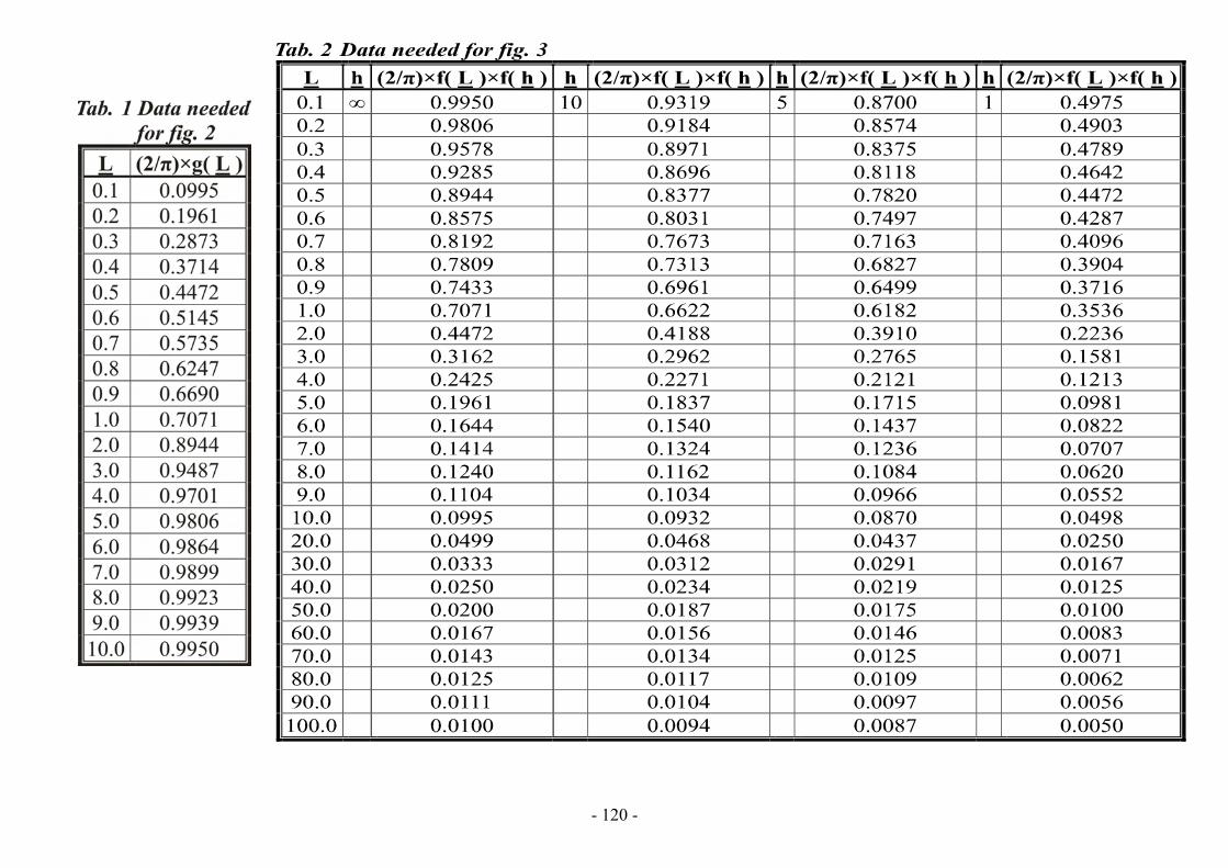
We ought to return again to function remarked as )L(g . On fig.2 there is depicted relationship � � )L(g�2 � . This relation varies between 1 and 0. If it holds that L � 7d it is valid that � � )L(g�2 � � 0.99 and this fact enable us to suppose that � � )L(g�2 � � 1 for condition that L � 7d. (Fig. 2 and the next figures have variables underlined below, because description of graphs in Excel with the help of Microsoft Equation 3.0 was not possible).
Analysis of function )L(f says that for L<< 1 it holds that )L(f = 1, whereas, for L>>1 it is written down that )L(f � (1/ L). It is also possible to express the following multiplication:
� �� �
� � .12
2arctg12
2arctg121
1
1,,f)(f 12 �
��
���
���
�
���
���
�
����
������
��� hzhz
LhzL
�(36)
If the tool is centred in the axis of borehole, it holds that = 0. If I suppose also that z = 0, I shall get that: - 121 -

Fig. 2 The relationship describing an influence of the tool spacing only
Fig. 3 The relationship describing an influence of the tool spacing and thickness of bed together
� �� �
.arctg2
1
1f)(f2
hL
hL ���
���
(37)
This relation reflects well those less accurate relations derived by DACHNOV, V.M. (1967), p.353. Relation (37) is depicted in fig. 3 there. Equation (34) is suitable for next adjustment.
� � ,,,f)(f81* ������ hzLK epe �� (38)
,d
ee
�� � (39)
where �e = the reduced real chargeability of rocks [m-1].Equations (30) and (38) are both equivalent one other. It is only different way of transcription.
- 122 -
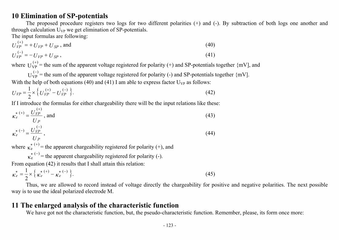
10 Elimination of SP-potentials The proposed procedure registers two logs for two different polarities (+) and (-). By subtraction of both logs one another and
through calculation UVP we get elimination of SP-potentials. The input formulas are following:
and,)(UUU SPVPVP ���� (40)
,)(UUU SPVPVP � � (41)
where = the sum of the apparent voltage registered for polarity (+) and SP-potentials together {mV], and U)(
VP�
= the sum of the apparent voltage registered for polarity (-) and SP-potentials together {mV]. U)(
VP
With the help of both equations (40) and (41) I am able to express factor UVP as follows:
� .21 )()(
UUU VPVPVP � �� (42)
If I introduce the formulas for either chargeability there will be the input relations like these:
and,)(
)(*
UU
P
VPe
�� �� (43)
,)(
)(*
UU
P
VPe
�� (44)
where = the apparent chargeability registered for polarity (+), and �)(*
e�
= the apparent chargeability registered for polarity (-). �)(*
e
From equation (42) it results that I shall attain this relation:
� .21 )(*)(** ���
� �� eee (45)
Thus, we are allowed to record instead of voltage directly the chargeability for positive and negative polarities. The next possibleway is to use the ideal polarized electrode M.
11 The enlarged analysis of the characteristic function We have got not the characteristic function, but, the pseudo-characteristic function. Remember, please, its form once more:
- 123 -

� � ,,,f)g(* ���� hzLee ��
� � � � .12
2arctg12
2arctg121,,f 1
���
���
���
�
���
���
�
����
������ hzhzhz�
To have the characteristic function we made make a small adjustment of both equations.
� �� �,,,f
12
* ���
��� hzL
Lee !�� (46)
� � and,122
1���� �! (47)
� � ,12
2arctg
122
arctg1,,f��
���
��
���
���
�
�
��
��
�
�
�
��
����
hzhzhz
� (48)
where � = the space angle, and � � ,h,zf = the characteristic function directed by formula (48).
These formulas are for particular case when the bed has no invasion there. If there is any invasion, the above formulas will getanother form.
� �� � ,,,,f
12
* DhzL
Liee ��
���� !�� (49)
� � ,22
1Di���� �! (50)
� � and,22arctg
22arctg1,,,f
��
���
��
���
���
�
���
���
�
����
���Dhz
DhzDhz
iii
� (51)
,dDD i
i � (52)
where Di = the depth of invasion zone.
- 124 -
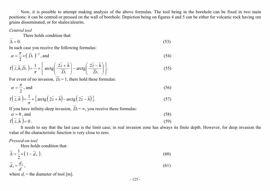
Now, it is possible to attempt making analysis of the above formulas. The tool being in the borehole can be fixed in two main positions: it can be centred or pressed on the wall of borehole. Depiction being on figures 4 and 5 can be either for volcanic rock having ore grains disseminated, or for shales/aleurits.
Centred tool There holds condition that: .0�� (53)
In such case you receive the following formulas:
� � and,2
1Di ��
�! (54)
� � .2arctg2arctg1,,f��
���
��
���
���
�
� ��
�
�
� ���
Dhz
DhzDhz
iii
�(55)
For event of no invasion, Di = 1, there hold these formulas:
and,2�! � (56)
� � � � � �� .2arctg2arctg1,f hzhzhz ����
(57)
If you have infinity-deep invasion, Di = �, you receive these formulas: and,0�! (58)
� � .0,f �hz (59)It needs to say that the last case is the limit case; in real invasion zone has always its finite depth. However, for deep invasion the
value of the characteristic function is very close to zero.
Pressed-on tool Here holds condition that:
� � .121
d s ��� (60)
,ddd s
s � (61)
where ds = the diameter of tool [m]. - 125 -

Then you get the following formulas:
� � and,22
1Dd is � ��� �! (62)
� � .1
2arctg
12
arctg1,,,f��
���
��
���
���
�
�
�
���
�
�
� �
��Ddhz
Ddhz
Ddhzisis
is � (63)
If you have a case of no invasion zone, Di = 1, you will receive these formulas:
� � and,22
1d s �� �! (64)
� � .22arctg
22arctg1,,f
��
���
��
���
���
�
�
���
�
� �
��d
hzd
hzdhzss
s�
(65)
If it is thick tool, d s = 1, it is case when tool is centred and pressed-on together.
and,2�! � � � � � � �� .2arctg2arctg1,f hzhzhz ���
�These are formulas valid for the centred tool. If it is thin tool, d s = 0, you will obtain other formulas.
and,4�! � (66)
� � .2
arctg2
arctg1,f��
���
��
���
���
�
� ��
�
�
����
hzhzhz�
(67)
For infinity-deep invasion you have to implement simpler condition that: � � .2 DDd iis �� � In such case there hold again formulas (58) and (59).
The formation water in an invasion zone is all replaced with mud filtrate. This is case of the free-water component. Effective porosityand permeability of bed is high; contribution of the bound-water is low, we suppose even that is zero. Therefore with growing of the depth of invasion zone we observe that the space angle and the characteristic function go to zero. And for very deep invasion there is no difference between the centred and pressed-on tools. The characteristic functions for the centred and pressed-on tools are in fig.4 and fig.5.
To both figures I should like to say a short remark. It is known that registration of chargeability of rocks is influenced too with the resistivity of rocks. Namely it is adjacent beds. This is confirmed by the analog modeling of the induced polarization over vertical desk. Even if it was done for case of the surface observation, we have to accept. The large amount of observations is published in KAROUS,
- 126 -

M. (1989). It means that an exact mathematical modeling made in this chapter has certain restricting conditions to the way used. Adjacent beds are not; we can suppose it is fresh air. In such case the resistivity of air would tend to infinity.
Fig.5 The characteristic function of the pressed-on toolFig. 4 The characteristic function of the centred tool
12 Peculiarities of using of the induced polarization in the boreholesIn Czech Republic method of the induced polarization began like surface exploration. It was focused on exploration of disseminated
ore deposits. The first works was published in sixty years; GRUNTORÁD, J., KN�Z, J., AND J�ZEK, M. (1972), KN�Z, J. (1967) and (1975). The surface observations were followed by works investigating the induced polarization on samples; KOZEL, J. and ONDRA, P. (1972). This all was focused on disseminated ores.
All system of the induced polarization was theoretically and transparently processed in the text-book focused on geoelectric methodsof exploration, KAROUS, M. (1989). There are in detail explained the frequent and pulse methods, published results of modeling and all is supported by vertical sections.
Later topic of the induced polarization was enlarged too for hydrogeology exploration. MAZÁ�, O. et al. (1981) and (1983). Investigation of the induced polarization began too to get into domain of boreholes. It was as the first the pulse method, however, very soon came up the frequent method. The induced polarization begins in the recent time to penetrate not only into domain of fresh water
- 127 -

prospection but too in hydrocarbon exploration. Interpretation of induced polarization in the boreholes offers to appreciate an effective porosity and through it permeability of beds too.
In the recent time you can use the induced polarization in the following domains: " Exploration of disseminated ore deposits; " Exploration of graphite and anthracite; " Exploration of fresh water; " Exploration of hydrocarbons.
In the Czech Republic in the recent time the last two domains are very perspective, mainly, for the borehole exploration. Registeringof the induced polarization in the boreholes has its peculiarities which are specific and which cannot be on the surface of Earth. Here exist a lot of very specific questions: " How observations are influenced with the borehole diameter; " How observations are influenced with the tool diameter; differences between thick and thin tools; " Has an influence on registration the tool position in the borehole and if it is, what is it; " What influence carries the tool spacing; " How to eliminate influence of the SP-potentials; " What influence have the important factors like thickness of bed and invasion zone are;
Those are questions being not when you register on the surface. The next questions are when you want to determine an effective porosity, possibly, permeability of beds too. " How to receive the final formula for interpretation of effective porosity; " How to get the value of the chargeability of the formation water; " How to interpret an effective porosity. These last three questions will be topics of the next chapter.
13 Geological interpretations of logs Let’s return again to those basic formulas. From these we can to interpret the real chargeability of rocks.
� � ,,,,f)(f* DhzL iee ����� !�� (68)
� �,
1)(f
2 ��
L
LL (69)
- 128 -

� � and,22
1Di���� �!
� � .22arctg
22arctg1,,,f
���
���
���
�
���
���
�
����
���Dhz
DhzDhz
iii
�The interpreted characteristic �e presents mixture of partial characteristics. The model of rock can be presented with the following
equation:� � � � ,1)()()(
21 pp mef
wef
wee pp � �� ��� �� �� (70)
where p = total porosity of rock, pf = effective porosity of rock,
= the chargeability of the free water for the dipole polarization, �(w)e1
= the chargeability of the bound water for the shifting polarization, �(w)e2
= the chargeability of the rock matrix for the shifting polarization. �(m)e
Most of sedimentary rocks do not contain sulfitic ores or anthracite. That is why that the characteristic tends to zero. On condition that � 0, you will get simpler form of equation (70).
�(m)e
�(m)e
� � ,)()(21 pp fw
efw
ee p �� �� �� � (71)
Now, it is affair of formation water only. The characteristic is stable, because does not depend on temperature. However, the
characteristic is dependent on temperature; with increasing of temperature is decreasing – the dipoles of free water get disoriented again. In the borehole there tends it rapidly to zero. If you implement condition that it holds that � 0, you will get simpler equation.
� �
�(w)e2
�(w)e1
�(w)e1
.)()(22
for, ���� weef
wee pp # �� (72)
This equation presents form which explains behaviour of different types of rocks. Aleurits and shales have highest deflections,because they have effective porosity close to zero. It presents that permeability such rocks is zero; however, their specific surface is very high. (pf << p). For shales it holds even that pf = 0.
Equation (71) can be written also like this:
,1)(2
pp
p fwee � �� �
�
���� (73)
- 129 -

Gypsum has lowest deflections of all rocks. It is imporous rock absorbing water only into its lattice. As p = 0 it holds that �e = 0. This explains behaviour of gypsum. Sands and sandstones have values somewhere between gypsum and shales. Here depends it on their effective porosity and total porosity together. Effective porosity is the primary factor; the secondary is total porosity. What is important is determining of characteristic . You determine it from the crossplot �e = f (p). You have relation �(w)
e2� �.The line of
shales/aleurits, because pf = 0, has and for p = 1 it holds . In contrary for absolutely permeable rock it holds that pf = p and results in
/pp1�tg f(w)e2
���
�tg(w)e2
�� �� (w)ee 2
�0tg �� .
Over here is only little remark. Gas like H2S is usual component of natural gas. In some cases it is the only one of the natural gas. Sulphur thanks its chemical reactions creates pyrite dispersion in shales and sands. Except the group of clean shales and sands we can receive two next clusters; both will be higher than the chargeability of clean rocks is. The highest positions have shales with pyrite, fragments of anthracite and graphitic pigment. The lower positions have sands/sandstones with disseminated ore grains, pyrite and graphite. This cluster just of these points can have higher dispersion than the one for the shales. Then you can expect higher/lower gap and it follows cluster of clean shales. The lowest positions have clean sands/sandstones; their dispersion will be probably too higher than for clean shales. The all storey structure was considered from the top downwards.
Therefore absolutely it would be serious mistake in the crossplot there to apply at all costs the line of shales, condition pf = 0, after the point having highest value of chargeability. You have to analyse which group belongs to clean shales and to determine the group of the pyrite grains shales. The before line you insert for the cluster of clean shales.
The right inserting of the line of clean shales has moreover next important significance, because separates beds having ore grainsfrom the beds without any grains. This fact is useable for sedimentary uranium deposits.
And finally, you obtain separation important too for hydrocarbons exploration, because it is known that rocks with pyrite form around hydrocarbons deposit a pyrite halo. KAROUS M. (1989).
If in the bed there are hydrocarbons present, equation (72) will change into form: � � � � � � ,1)()(
22spsp wf
hewf
wee pp � ��� �� ��� (74)
It holds that >> ; therefore the beds having hydrocarbons have much lower deflections than those having only fresh water. It is characteristic for conditions in Vienna Basin and in Pannonia Basin of Western Slovakia. What is interesting is it does not hold for salt water. High content of salt in water means rapid fall of the characteristic . For salt water it holds that � . Then it is impossible to differ between hydrocarbons and salt water; it is case of Eastern Slovakia.
�(w)e2
� )h(e2
�(w)e2
�(w)e2
� )h(e2
The next region, where fresh water is, is almost all Bohemian Massif when you made locate and bound oil contamination from various sources in fresh water. This is important in the recent time when the sources of fresh water are close to disaster by oil outflows.
- 130 -

Interpretation of effective porosity supposes that you know difference (p – pf) after equation (72) and the value of total porosity p. Effective porosity is defined then like that:
� � � �.for ppppppp fff $ � (75)
Calculation of expression � �pp f is easy, because numeric characteristics both are well known. For interpretation of the rock permeability you can use either individual relations constructed between an effective porosity and permeability, or the derived equations. The basic is Kozeny-Karman equation, the all next are usually variances of that.
�and� (w)ee 2
14 Calibration of the induced polarization method Calibration needs to have a calibrator being the part of equipment. The apparent chargeability of rock is defined owing to formula:
.*
UU
P
VPe �� (76)
This is ratio of two voltages; the mentioned calibrator must consist of two independent voltage sources having accurately calibrated values in [mV]. On the output of calibrator there is ratio (U1/ U2) which simulates the apparent chargeability. This voltage ratio presents the standard-signal for calibration.
If we use a linear scale, the only etalon of the apparent chargeability is enough, nevertheless, for non-linear scale you will need to have all set of such etalons. The etalon made with calibrator can be expressed in this form:
,2
10 U
U�� (77)
where �0 = the simulated apparent chargeability. Deflection reflecting � 0 you get after this formula:
,00 nl �� (78)
where n = the step of linear scale [� /1cm], l = deflection on the log [cm]. 0Both voltage sources must be under metrological control; they present primary standard. The right adjustment and right function of
equipment needs to have a test pit with fresh water. Verification of all registration system including the electrode tool, too, is made in the mentioned pit having big radius enough. The fresh water presents then the secondary etalon derived from calibrator of equipment. It allows us to control stability of equipment.
- 131 -

15 Conclusions Due to analysis of the deduced relations being in accordance to experimental observations I reached these items:
" As the registered factor of the induced polarization method it is the chargeability of rocks. If you register the time spectrum, then here is the next factor – the relaxation time of the polarization field;
" The sulfitic ores and anthracite have the electron-shifting polarization. The sedimentary rocks have both the dipole polarization and the ion-shifting polarization, the first being dependent on temperature with increasing of depth dies;
" The real chargeability is dimensionless factor. We can also interpret the reduced chargeability of rocks which is dimensional factor remarked [m – 1];
" The induced polarization method can be used for location of sulfitic ores or anthracite. The tool ought to be centred for well separation of very thin beds;
" For sedimentary rocks the induced polarization method is recommended for prospecting of hydrocarbons in those rocks saturated withfresh or brackish waters. The hydrocarbons have the shifting polarization. An increasing salinity of formation water tends to elimination of differences between the beds having hydrocarbons and those having no hydrocarbons;
" Calibration of the method is made with the help of two voltage sources simulating the chargeability like a ratio. This apparentchargeability is used for calibration of logs.
References
BODMER, R., WARD, S.H., and MORRISON, H.F. On induced electrical polarization and groundwater, Geophysics, v. 33, no. 5, 1968, p. 805– 821. CAHYNA, F., MAZAC, O., and VENDHODOVA, D. Determination of the Extent of Cyanide Contamination by Surface Geoelectrical Methods. Geotechnical
and Environmental Geophysics, Vol 2, Society of Exploration Geophysicists, Tulsa, OK, 1990, pp 97– 99.DACHNOV V.N. Elektritcheskye i magnitnye metody issledovanya skvazhin-Fundament of theory, Nedra, Moscow, 1967 DOBRYNIN V.M. Interpretecya rezultatov geofyzitcheskych issledovanyi neftyanych i gazovych skvazhin, Handbook, Nedra, Moscow, 1988 GRUNTORÁD, J., KN�Z, J. and J�ZEK, M. Geoelektrika I – Vyzvaná polarizace, P�F UK, Praha, 1972 KAROUS, M. Geoelektrické metody pr�zkumu, SNTL/ALFA, Praha, 1989,423 p KN�Z, J. Metodika a technika m��ení metodou vyzvané polarizace, Kan. Dis., P�F UK Praha, 1967 KN�Z, J. Metoda vyzvané polarizace p�i vyhledávání a pr�zkumu zakrytých rudních ložisek, Habil. práce, P�F UK Praha, 1975 KOMAROV, V. A., PISHPAREVA, H., SEMENOV, M. and KHLOPONINA, L. Theoretical Fundamentals for Interpretation of Survey Data Obtained with the
Induced Polarization Method, Leningrad, Isdatel'stov Nedra, 1966 KOZEL, J. and ONDRA, P. Výzkum vynucené polarizace hornin, Záv. Zpráva, Geofyzika, Brno, 1972 LUO, Y., and ZANG G. Theory and application of spectral induced polarization: SEG, 171, 1998 MAZÁ�, O. et al. Vývoj racionálního komplexu geofyzikálních metod pro hydrogeologii, Záv. zpráva, etapa 1978 – 1981, Geofyzika, Praha, 1981 MAZÁ�, O. et al. Optimalizace geofyzikálního pr�zkumu v rozdílných hydrogeologických podmínkách, Etapa 1981 – 1983, výzk. Zpráva, Geofyzika, Praha, 1983SEIGEL, H. O. Mathematical Formulation and Type Curves for Induced Polarization. Geophysics, Vol 24, No. 3, 1959, pp 547– 565.
- 132 -
- 133 -
SEIGEL, H. O. The Induced Polarization Method in Mining and Groundwater Geophysics, Geological Survey Canada, Economic Geology Report 26, 1970 WIGHTMAN, W. E., JALINOOS, F., SIRLES, P., and HANNA, K. Application of Geophysical Methods to HighwayRelated Problems, Federal Highway
Administration, Central Federal Lands Highway Division, Lakewood, CO, Publication No. FHWA-IF-04-021, September 2003.http://www.cflhd.gov/resources/agm/
WORTHINGTON, P.F. The relevance of induced polarization to quantitative formation evaluation, Society of Professional Well Log Analysts, Annual Logging Symposium, 23rd, Corpus Christi, Tex., 1982, Transactions, p. U1-U42, 1982
ZHDANOV M. S. Generalized effective medium theory of induced polarization, University of Utah, SEG/New Orleans 2006, Annual Meeting, 2006 Author1 RNDr. František Ryšavý, Lesní 3, 695 03 Hodonín, Czech Republic, [email protected]