Embed Size (px)
Citation preview

University of WollongongResearch Online
Faculty of Engineering and Information Sciences -Papers: Part A Faculty of Engineering and Information Sciences
2015
High strength and ductility of ultrathin laminatefoils using accumulative roll bonding andasymmetric rollingHailiang YuUniversity of Wollongong, [email protected]
A Kiet TieuUniversity of Wollongong, [email protected]
Syamsul [email protected]
Cheng LuUniversity of Wollongong, [email protected]
Ajit R. GodboleUniversity of Wollongong, [email protected]
See next page for additional authors
Research Online is the open access institutional repository for the University of Wollongong. For further information contact the UOW Library:[email protected]
Publication DetailsYu, H., Tieu, A. Kiet., Hadi, S., Lu, C., Godbole, A. & Kong, C. (2015). High strength and ductility of ultrathin laminate foils usingaccumulative roll bonding and asymmetric rolling. Metallurgical and Materials Transactions A: Physical Metallurgy and MaterialsScience, 46 (2), 869-879.
High strength and ductility of ultrathin laminate foils using accumulativeroll bonding and asymmetric rolling
AbstractAs product miniaturization is becoming widely popular, many microparts are being produced bymicroforming of sheets/foils, whose strength needs to be able to maintain structural stability of the micro-components. In addition, their strength and ductility of foils generally reduce with a reduction in thethickness due to the size effect. In this paper, we report the fabrication of an aluminum laminate foil using acombined process of accumulative roll bonding (ARB) and asymmetric rolling (AR). It was found that thisimproves both strength and ductility. TEM results show that the laminate structures produced by ARBdevelop an inhomogeneous microstructure with nanoscale grains and abnormal coarsening in some grainsduring AR processing. Both these effects result in an improved ductility and strength. Using these rolledproducts, micro-cups of very small wall thickness/cup diameter ratio (1/200) have been successfullyfabricated by micro-deep drawing without the need for annealing.
KeywordsAluminum alloy; Nanostructure; Abnormal grain growth; Rolling; Deep drawing; Ultrathin laminate foil
DisciplinesEngineering | Science and Technology Studies
Publication DetailsYu, H., Tieu, A. Kiet., Hadi, S., Lu, C., Godbole, A. & Kong, C. (2015). High strength and ductility ofultrathin laminate foils using accumulative roll bonding and asymmetric rolling. Metallurgical and MaterialsTransactions A: Physical Metallurgy and Materials Science, 46 (2), 869-879.
AuthorsHailiang Yu, A Kiet Tieu, Syamsul Hadi, Cheng Lu, Ajit R. Godbole, and Charlie Kong
This journal article is available at Research Online: http://ro.uow.edu.au/eispapers/3306

High Strength and Ductility of Ultrathin Laminate Foils Using
Accumulative Roll Bonding and Asymmetric Rolling
HAILIANG YUa,b*, KIET TIEUa, SYAMSUL HADIa,d, CHENG LUa, AJIT GODBOLEa, CHARLIE KONGc
a School of Mechanical, Materials & Mechatronics Engineering, University of Wollongong, NSW
2500, Australia.
bSchool of Mechanical Engineering, Shenyang University, Shenyang 110044, China.
c Electron Microscope Unit, University of New South Wales, Sydney, NSW 2052, Australia.
d Mechanical Engineering Department, State Polytechnic of Malang, P.O. Box 04 Malang 65100,
East Java, Indonesia
Abstract: As product miniaturization is becoming widely popular, many microparts
are being produced by microforming of sheets/foils, whose strength needs to be able
to maintain structural stability of the micro components. In addition, their strength and
ductility of foils generally reduces with a reduction in the thickness due to the size
effect. In this paper, we report the fabrication of an aluminum laminate foil using a
combined process of Accumulative Roll Bonding (ARB) and Asymmetric Rolling
(AR). It was found that this improves both strength and ductility. TEM results show
that the laminate structures produced by ARB develop an inhomogeneous
microstructure with nanoscale grains and abnormal coarsening in some grains during
AR processing. Both these effects result in an improved ductility and strength. Using
these rolled products, micro-cups of very small wall thickness/cup diameter ratio
(1/200) have been successfully fabricated by micro deep drawing without the need for
annealing.
Keywords: Aluminum alloy; Nanostructure; Abnormal grain growth; Rolling; Deep
drawing; Ultrathin laminate foil * Corresponding author: YU H.L., [email protected] or [email protected]

I. INTRODUCTION
Product miniaturization is a trend for facilitating product usage, enabling product
functions to be implemented in microscale geometries, and aimed at reducing product
weight, volume and cost.[1] A number of microchannels and microcups have been
produced by sheets/foils microforming.[2, 3] The smaller the microparts, the thinner the
foils need to be. These foils should be strong enough to maintain the structural
stability of the microparts. In addition, the size effects on the behavior of
microformed materials have assumed an increasing importance.[4-6] For rolled
monolayer foils, the size effect is often evident in drawn cups. Recently, Fu and
Chan[7] carried out a review of microforming technologies, and they noted that the
fracture strain decreased with a reduction in the workpiece size in tensile tests on
sheet metal. It was observed that fracture results from localised shear in individual
grains. Thin cold-rolled and annealed copper foils of varying thicknesses with a
scaled geometry and comparable microstructure were tested in tension by Simons et
al.[8] They found that when the foil thickness was reduced from 250 μm to 10 μm, the
fracture strain decreased from approximately 0.2 to 0.002 for cold-rolled foils and
from 0.35 to 0.15 for annealed foils respectively. To study the size effects on fracture,
Fu and Chan[9] conducted tensile tests on annealed pure copper foils with varying
thicknesses and grain sizes. It was found that the flow stress, fracture stress/strain and
the number of microvoids on the fracture surface decreased with decreasing specimen
size/grain size ratio. Nanostructured/ ultrafine-grained sheets/foils fabricated using
Severe Plastic Deformation (SPD) techniques can be used to offset size effects on

workpieces during microforming and to improve the structural stability of microparts.
Ma et al.[10] used an SPD technique, called equal channel angular pressing, to
fabricate ultrafine-grained copper sheets which were subsequently manufactured in a
micro deep drawing process. They found that the ultrafine-grained copper has
potential applications in microforming. These considerations suggest that it would be
interesting and significant to produce nanostructured sheets/foils with special
properties.
Special properties such as high strength and ductility of nanostructured materials
have attracted widespread attention from researchers.[11-13] Variants of the SPD
techniques such as asymmetric cryorolling,[14, 15] Accumulative Roll Bonding
(ARB)[16, 17] and Asymmetric Rolling (AR)[18, 19] have been developed to enable bulk
fabrication of nanostructured/ultrafine-grained metal sheets/foils. The ARB and AR
techniques can be used to produce continuous products and are more feasible for
practical application in industries. The ARB technique was developed by Tsuji et al.[16]
and has been used successfully to produce nanostructured/ultrafine-grained
specimens[16, 17]. In the AR process, sheets/foils are passed between rolls that either
have different diameters or rotate at different angular speeds. AR is also considered a
potential technology for production of nanostructured/ultrafine-grained materials. It is
possible to obtain a quasi-uniform shear strain distribution through the thickness of
the material under certain rolling conditions. AR-processed Al sheets[19] and
bimetallic foils[18] show an excellent ductility during tensile tests. In addition, the AR
technique can produce thinner foils. AR is different from conventional rolling as

regards parameters such as rolling load, shear strain, and minimum permissible
thickness[20]. AR has a significant potential for a variety of industrial applications
because it requires lower rolling pressure while simultaneously improving the product
shape. The influence of the roll speed ratio on reduction in unit pressure on the rolls
was studied by Kawalek et al.[20] They found that the magnitude of the total rolling
force could be reduced by 27% by AR.
Generally, ductility and strength are conflicting properties in nanostructured bulk
metals.[21] In addition, with ever-thinner foils, the size effect results in reduced
ductility and higher strength.[22] In the present study, we combined the ARB and AR
techniques to produce aluminum laminate foils composed of 416 layers. TEM results
show that the laminate structures by ARB changes into inhomogeneous
microstructure with nanoscale grains and some abnormal coarse grains during AR.
This results in improved foil ductility and strength. The ARB- and AR-processed foils
were successfully used to produce micro-cups without fracture.
II. EXPERIMENTAL PROCEDURE
Aluminum AA1235 sheets with 300 μm thickness were used. The main chemical
composition (mass %) of the material used was Al=99.35, Fe=0.42, Si=0.10, Ti=0.02,
Zn=0.012, Ni=0.003, Mn=0.002, Cu=0.001, and others.
The ARB experiments were carried out on a Hille-100 rolling mill. The AR
experiments were carried out on the ARB-processed sheets on a multifunction rolling
mill. The rolling speed ratio between the upper and lower rolls was set as 1.3, which
results in the best bonding during laminate AR.[23] Fig. 1 shows a schematic

illustration of the process. In Step 1, 13 layers (each 300 μm thickness) were stacked
and were rolled to 390 μm in one pass. In Step 2, the rolled multilayer laminates were
cut into two halves, surface treated, stacked, and rolled with a reduction ratio of
around 56% at a temperature of 473 K[24] in order to achieve a good bonding quality.
After five ARB cycles, foils made up of 416 (13×25) layers were produced, and the
final foil thickness was 205 μm. In Step 3, the ARB-processed sheets were subjected
to two AR passes at room temperature. The thickness of foil was 85 μm and 45 μm
after the first and second AR passes respectively.
Fig. 1- Illustration of the processing schedule for nanostructural foils.
Tensile tests with a strain rate of 1.0×10⁻³ s-1 were carried out on the foil samples
using an INSTRON machine. The tensile tests were carried out three times for each
thickness. Subsequently, an FEI xT Nova Nanolab 200 Dualbeam workstation was
used to prepare thin foil specimens from the rolled samples for TEM observation. A
Philips CM200 Field Emission Gun Transmission Electron Microscope (FEG/TEM)
equipped with a Bruker Energy Dispersive X-ray (EDAX) Spectroscopy system
operating at an accelerating voltage of 200 kV was used to investigate the details of
the microstructure. The Digital Micrograph software was used to determine the grain

size in the TEM images. The morphology of the fractured surface of samples was
studied with a Zeiss Auriga Field Emission Scanning Electron Microscope (FESEM)
operating at 20 kV, with a working distance of about 15 mm. Finally, rolled foils
having a thickness of 45 μm were used to produce micro-cups of diameter 8.26 mm
with a blank diameter of 14 mm.
III. RESULTS
The engineering stress vs. engineering strain curves during tensile testing of the
annealed and ARB- and AR-processed foils are shown in Fig. 2. The engineering
fracture strain of the annealed sheets is 0.064. After the fifth ARB pass, it reduces
slightly to 0.055. After the first AR pass, the engineering fracture strain reduces to
0.048. However, after the second AR pass, the engineering fracture strain increases to
0.057. In the present experiments, we found no reduction in engineering fracture
strain although the foil thickness was reduced by 85%. In addition, we found that the
tensile strength increases significantly, as seen in Fig. 2. After the fifth ARB pass, the
tensile stress is 133 MPa. After the second AR pass, the tensile stress increases into
147 MPa, an increase of 10.5% over the ARB-processed samples.

Fig.2- Engineering stress vs engineering strain curves of laminate sheets/foils.
Figures 3a to 3f show the progressive change in the sample microstructures. In Fig.
3a, the original sheet is seen to be composed of coarse grains, which undergo
refinement during the rolling process. With an increase in the number of rolling passes,
the grain size gradually decreases. In ARB processing, the grains were refined to
laminate structures, as shown in Fig. 3c. After the first AR pass, some of laminate
grains were seen to coarsen and while other grains were further refined. With
subsequent rolling passes, the rolled laminate structure grains change into refined
equiaxed grains, as shown in Fig. 3f.
Figures 4a to 4e show the progressive change in grain size distribution of the
samples. Fig. 4f shows the mean and the maximum grain size after each pass. After
the second ARB pass, the mean grain size is 731 nm, the maximum grain size is 1150
nm, and most of grains range from 600 nm to 900 nm in size, as shown in Fig. 4a. In
Fig. 4b, the grains are seen to be further refined. The mean grain size is reduced to

507 nm, and the maximum grain size is also reduced to 846 nm. In addition, the
majority of grains range from 400 nm to 700 nm in size. After the fifth ARB pass, the
mean grain size is reduced slightly to 486 nm, while the maximum grain size is still
around 850 nm. Fig. 4c shows that most of grains range from 300 nm to 600 nm in
size. However, in the AR process, the maximum grain sizes and the mean grain size
change in two contrary directions. As shown in Fig. 4d, the maximum grain size
grows to 989 nm, and the mean grain size continues to decrease to 462 nm. Grains
ranging from 300 nm to 400 nm in size are obvious more than others. After the second
AR pass, there are more coarse grains and the maximum grain size reaches 1126 nm,
but the mean grain size decreases further to 441 nm. The majority of grains range
from 200 nm to 600 nm in size. It is obvious that this change in grain size during AR
improves both the strength and the ductility of the foils. As seen in Fig. 4f, the mean
grain size decreases continuously, and the reduction after the fifth ARB pass is small.
In addition, the maximum grain size decreases continuously in the ARB process, and
increases in the AR process.

Fig. 3- TEM images of samples. (a) initial sheet, (b) after the second ARB pass, (c) after the
third ARB pass, (d) after the fifth ARB pass, (e) after the first AR pass, and (f) after the
second AR pass.

Fig. 4- Grain size distribution after the second ARB pass (a), the third ARB pass (b), the
fifth ARB pass (c), the first AR pass (d), the second AR pass (e) and the mean and the
maximum grain size after different rolling passes (f).
Fig. 5 shows the images of typical fracture profiles for the annealed, ARB- and
AR-processed samples after a tensile test. Before rolling process, the fracture angle of
test sample is 69º. With the ARB and AR passes, the fracture angles of samples
gradually decreases. After the fifth ARB pass, the fracture angle of sample reduces to
63º, which becomes 60º after the second AR pass. This fracture angle value is similar
to the observation in Refs. [25, 26], which is a typical fracture angle value for the

nanostructured foils such as Al, Cu and Ni-Fe after tensile test.
Fig. 5–Image of typical fracture profiles for samples Before Rolling (BR), after the fifth ARB
pass (ARB5), the first AR pass (AR1) and the second AR pass (AR2).
Fig. 6 shows SEM images of the fracture surfaces of the samples after a tensile test.
The annealed aluminium sample shows a high ductility, and there are large and deep
dimples on the fracture surface, as shown in Fig. 6a. However, the ductility of the
samples after the fifth ARB pass reduces greatly,[16] in which the dimples are smooth
and shallow, as shown in Fig. 6b. As seen in Fig. 6c and Fig. 6d, after the AR
processing, the density of the dimples on the fracture surface increases compared with
that after the fifth ARB pass. This indicates an improvement in the ductility during the
AR process.
For nanostructured foils, it has been suggested that the area reduction ratio is a good
measure of their ductility.[25] From volume conservation, the final cross-sectional area
(Afinal) can be converted into a true fracture strain, as shown in Eq. (1)[25],
1ln( / ) ln( )
1axial initial finalA Aq
(1)
where Ainitial is the cross-section area before the tensile test, q is the area reduction
ratio. As shown in Fig. 6, the thicknesses after necking are 40.8 m, 146.2 m, 42.4
m and 9.9 m for the samples before rolling, after the fifth ARB pass, the first AR

Fig. 6–SEM images of fracture surfaces (a) before rolling, (b) after fifth ARB pass, (c)after
the first AR pass and (d) after the second AR pass.
pass and the second AR pass respectively. The true fracture strains for the samples
were calculated using Eq. (1). Fig. 7 shows the area reduction ratio and true fracture
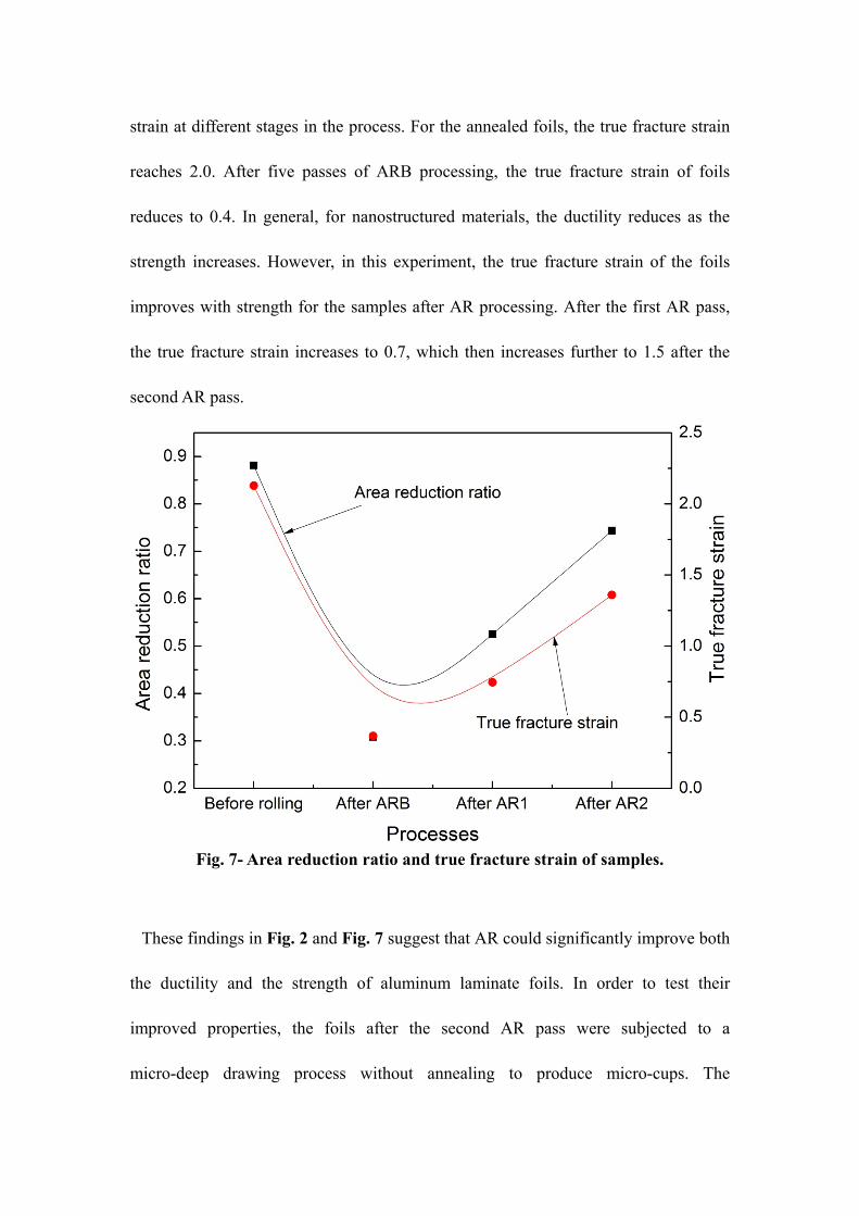
strain at different stages in the process. For the annealed foils, the true fracture strain
reaches 2.0. After five passes of ARB processing, the true fracture strain of foils
reduces to 0.4. In general, for nanostructured materials, the ductility reduces as the
strength increases. However, in this experiment, the true fracture strain of the foils
improves with strength for the samples after AR processing. After the first AR pass,
the true fracture strain increases to 0.7, which then increases further to 1.5 after the
second AR pass.
Fig. 7- Area reduction ratio and true fracture strain of samples.
These findings in Fig. 2 and Fig. 7 suggest that AR could significantly improve both
the ductility and the strength of aluminum laminate foils. In order to test their
improved properties, the foils after the second AR pass were subjected to a
micro-deep drawing process without annealing to produce micro-cups. The

micro-cups are shown in Fig. 8. In these 8.26 mm diameter cups, the wall thickness is
less than 45 μm, which is only 1/200 of the cup diameter. There are no fractures seen
on the cup walls, implying that the laminate foils have a high ductility. Some wrinkles
were observed due to high compressive stress on the thin wall.
Fig. 8- Micro-cups without fracture with nanostructured laminate foils of thickness 45 μm
after the second AR pass without annealing.
IV. DISCUSSION
A. Strength and ductility improvement of nanostructured laminate foils
As shown in Fig. 2, the yield strength of foils improves as a result of ARB and AR.
It is easy to understand the improvement in yield strength of the foils in terms of the
Hall-Petch relationship:
Dk yy /0 (2)
where y is the yield stress after deformation, 0 the yield stress after annealing, ky the
Petch parameter, and D the mean grain size. As seen in Fig. 4f, the yield stress of the
foil increases with a reduction in the mean grain size.
The improvement in both strength and toughness is a vital requirement for most

structural materials. However, for some nanostructured metals, ductility and strength
are generally conflicting properties. As described by Ritchie,[21] as the quest continues
for stronger and harder materials, bulk structural materials without an appropriate
fracture resistance have little to no use. Thus, for nanostructured metals, it is
important to improve their ductility, which generally could be improved by the
following methods: (1) Reducing stacking fault energy and increasing solute content:
Huang et al.[27] analyzed the effect of stacking fault energy on the equilibrium grain
size and tensile properties of nanostructured copper and copper-aluminum alloys.
They reported that with increasing solute content and decreasing stacking fault energy
not only the strength but also the ductility of nanostructured copper alloys increased
substantially. Yu et al.[15] analyzed the improvement in ductility by ageing in AA6061
samples. Due to a high density of nanosized precipitates formed during ageing, a
higher number of dislocations are accumulated, which results in enhanced ductility.
Lu et al.[28] carried out cold rolling experiments on bulk nanocrystalline pure copper.
They pointed out that the super-plastic deformation of nanocrystalline copper
originates from a deformation mechanism dominated by grain boundary activity
rather than lattice dislocation. (2) Application of nanotwins: Shen et al.[29] tested the
tensile properties of an electro-deposited Cu sample with a high density of nano-scale
growth twins. They found that both the strength and the ductility increase with a
decrease in thickness of the twin lamellae. Wei et al.[30] reported a way of enhancing
the strength of twinning-induced plasticity steel with no ductility trade-off. (3)
Controlling the grain size distribution: Fang et al.[31] reported experiments on a

nano-grained copper film confined by a coarse-grained copper substrate with a
gradient in grain-size transition. The sample exhibited a ten-fold increase in the yield
strength and a tensile plasticity comparable to that of the coarse-grained substrate.
The samples could sustain a tensile true strain exceeding 100% without cracking.
Wang et al.[32] reported a mechanism for developing an inhomogeneous
microstructure in nanostructured copper where strain hardening mechanisms can
stabilize the tensile deformation, and lead to a high tensile ductility.
In the current study, we found an inhomogeneous microstructure combined with
nanosize grains and abnormal coarse grains in AR-processed samples. This is similar
to the observation reported in Ref. [32]. As shown in Fig. 4d and 4f, the majority of
grains reduce in size with a higher rolling deformation, but some grains are seen to
coarsen abnormally. As shown in Fig. 3b and Fig. 3c, in the ARB process, the grains
were refined to nanosized laminated structures. In the AR process, some laminate
grains grow abnormally to become coarse grains, while most of the remaining grains
are further refined, as shown in Fig. 3f. In Fig. 4f, both the mean grain size and
thickness of foil after the first AR pass are reduced compared with that after the fifth
ARB pass, but the ductility of the foil increases slightly (In Fig. 7) due to the
appearance of coarse grains during the first AR pass as shown in Fig. 4d. It is seen in
Fig. 4e that after the second AR pass, the frequency of coarse grains increases. This,
in turn, greatly increases the foil ductility.
B. Abnormal grain growth mechanism during AR
It is easy to understand why an increase in strain brings about grain refinement. The

relationship between dislocation density and strain is shown in Eq. (3):[33]
1)( blg (3)
where g is the total generated dislocation density, b the Burgers vector, l the mean
free path for dislocation movement, and the strain. However, as shown in Fig. 4f,
some grains are seen to grow abnormally during AR.
Generally, if the temperature of sample is higher than a certain threshold value, the
grains will grow in size. At high temperature, materials show both normal continuous
grain growth and abnormal discontinuous grain growth. During an abnormal grain
growth, the difference in individual grain size increases due to some of the grains
growing rapidly.[34] Hillert[34] believed that the abnormal grain growth could develop
in a material annealed at high temperature under three conditions: (i) normal grain
growth cannot take place due to the presence of second-phase particles, (ii) the
average grain size is less than a certain value, (iii) there is at least one grain much
larger than the average. It is obvious that none of the above three conditions can
explain the abnormal grain growth seen in Fig. 3f. During AR, the temperature rise of
the foils increases with increasing roll speed ratio. But, when the reduction is about
40%, the temperature rise of the foils is generally less than 373 K.[35] Yu et al.[36]
analyzed the recovery mechanisms in nanostructred aluminium when the temperature
is less than 373 K. The laminate boundaries are generally flat, with the curvature
maximum at triple junctions. The boundary velocity v is usually assumed to be
proportional to the driving pressure P, with the mobility M as the proportionality
factor (v=PM). If the migration is thermally activated and the driving pressure is given
as a function of the boundary curvature (P=2/r), the boundary velocity will be:
)exp(2
0 RT
QM
rv b
(4)
where is the boundary energy, r the radius of curvature, M0 a pre-exponential
constant, and Qb the activation energy for boundary migration. It was found that for
pure aluminium during grain growth,[36] M0 = 0.125 m4J-1s-1, Qb = 130 kJmol-1, and
= 0.324 Jm-2 for a high angle boundary. Therefore, when the temperature of the foils
rises to 373 K for radius of curvature r = 50 nm, the velocity will be 3.5×10⁻¹² ms-1.
Because the rolling process lasts only for a few seconds, the temperature rise during
AR causing the grain boundary migration can be neglected.
Besides the grain growth driven by temperature, shear stress also could drive the
grain boundary migration and result in grain growth. Haslam et al.[37] proposed two
grain growth mechanisms during the deformation: (1) growth due to curvature-driven
grain boundary migration and (2) growth resulting from grain rotation-induced
coalescence. Generally, the AR process leads to a higher shear stress compared with
the conventional rolling process. Fig. 9 shows the shear stress distribution in the roll
deformation zone compared with conventional rolling and AR by finite element
simulation. It is obvious that the AR produces higher shear stress.
It is widely acknowledged that shear stresses can induce dislocation motion. The
motion of low-angle grain boundaries, which consist of dislocation arrays, under
shear stress can be described by the collective movement of the individual
dislocations in these boundaries.[38] In addition, shear stress promotes texture
evolution during grain growth, and grain growth can serve as a stress relief

Fig. 9- Shear stress distribution when the foil is rolled from 205 m to 85 m (with the
same reduction ratio in first AR pass) by (a) conventional rolling and (b) AR.
mechanism in both elastically isotropic and anisotropic materials, and can also
promote plastic yielding. Rollett et al.[39] believed that the abnormal grain growth can
occur by two distinct mechanisms. Both of these mechanisms are related to anisotropy
in the properties of the grain boundaries: anisotropic grain boundary energy and
mobility. Shear stress applied to a grain boundary can induce its normal motion.
Stress-induced grain boundary migration can cause grain shape change and grain
rotation, leading to plastic deformation of polycrystalline materials without diffusion
or slip in the grains. Washburn and Parker[40] investigated planar low-angle grain
boundaries in Zn under the influence of an external shear stress and observed the
continuous motion with polarized light in an optical microscope. Shan et al.[41]
reported in situ dynamic TEM observations of nanocrystalline nickel films with an
average grain size of about 10 nm, which show that the grain boundary-mediated
process is a prominent deformation mode. According to traditional conception, a

mechanical stress does not couple with a high-angle boundary. Winning et al.[42]
pointed out that at high temperatures the response of high-angle grain boundaries to
shear changes from coupling to sliding until the coupling disappears. In 2005,
mechanical grain growth was observed by Zhang et al.[43] in nanocrystalline Cu under
an indenter at liquid nitrogen temperature. They found the grains grew from 20 nm to
400 nm at cryogenic temperature after 30 minutes. Li et al.[44] pointed out that the
material must be pure enough so that free dislocations are available to move out of the
boundary. But the boundary should not be in the lowest-energy state so that extra
dislocations are available to be emitted by stress. For ARB-processed sheets, there
should be some oxygen atoms at the interface between layers. Tang et al.[45] found
that the oxygen atoms pin the boundaries, preventing stress-assisted grain growth. In
addition, for ARB-processed pure aluminum laminates, most of grains are high-angle
grains, and there are some solute elements in the matrix. Thus the grain growth caused
by stress-driven grain boundaries migration is also difficult at low temperature (less
than 373 K).
In 2002, Moldovan et al.[46] proposed a grain growth mechanism: grain rotation
leading to coalescence of neighboring grains via elimination of the common grain
boundary between them. They assumed that the grain boundary energy depends on the
misorientation angle between any two neighboring grains, and the change of the
orientation of one grain due to rotation leads to a change in the misorientations of all
the grain boundaries surrounding the grain change. When two neighboring grains
assume the same orientation, they coalesce forming a single larger grain. Wang et al.

[47] used nanobeam electron diffraction and a series of dark field images technique to
investigate the deformation mechanism of nanocrystalline Ni in response to in situ
tensile deformation under TEM. They validated the deformation-induced grain
rotation and growth mechanism. Fig. 10 shows an abnormally coarse grain resulting
from AR processing in a detail of Fig. 3f. In the figure, the merging of four grains into
a coarse grain can be seen. From the analysis above, in this growth mechanism, it is
likely that four grains grow into a coarse grain due to stress-induced grain rotation
during AR.
Fig. 10- Abnormal grain growth by four grains in foil during AR.

C. Thickness size effect in nanostructured laminate foils
For metallic sheets and foils, thickness size effects are significant.[22] Suh et al.[48]
found that the tensile strength and ductility of Al 6K21-T4 sheets decreased almost
linearly with a reduction in thickness, when the thickness was less than a critical value.
With a reduction in the sheet thickness, the grains on the free surface are less
constrained and can be deformed more easily at a substantially lower flow stress than
is the case in the bulk state. As shown in Fig. 11a,[48] for annealed Al 6K21-T4 sheets
of grain size 40 m, as the thickness of the sheet is reduced from 1600 m to 400 m,
the engineering fracture strain is reduced from 0.25 to 0.15 and the tensile stress also
decreases slightly. A similar phenomenon was also observed by Simons et al.[8] who
carried out tensile tests on thin rolled & annealed copper foils of different thicknesses.
As shown in Fig. 11b, when the thickness is reduced from 250 μm to 10 μm, the
fracture strain decreases from 0.35 to 0.15 for annealed samples with grain size 15 m.
However, as shown in Fig. 11c, the strength of the foils increases greatly after ARB &
AR. The engineering fracture strain of the foils also increases slightly, although the
thickness of foils decreases significantly in the present study. The thickness of the
annealed sheets is 300 μm, and the thickness of the foils after the second AR pass is
reduced to 45 μm. In addition, as shown in Fig. 7, the true fracture strain of the
ARB-processed foils increases from 0.4 to 1.5 after two AR passes. At this point, the
tensile stress increases by 21% and the ductility of the foils is much greater than that
with thickness 205 μm after the ARB process.

Fig.11- Thickness size effect during tensile process, (a) for Al 6K21-T4 with coarse
grains,[48] (b) for annealed pure Cu foils,[8] and (c) for the samples in current experiments.
For metal sheets and foils with coarse grains, with a reduction in the sample
thickness, the grains on the free surface are less constrained and more easily deformed
at a substantially lower flow stress than is the case in the bulk state. Kals et al.[49]
expressed the volume fraction of grains having a free surface, as shown in Eq. (5):
wt
dtdw )2)(2(1
(5)
where w is the specimen width, t the specimen thickness, and d the average grain size.
When the specimen width is much larger than the grain size (w>>d), Eq. (5) can be

simplified to:
t
d2 (6)
Generally, as the thickness decreases, the relative surface area per volume of a
specimen increases. In the experiments by Suh et al., is 0.5% when the thickness is
1600 μm, increasing to 20% when the thickness is 400 μm. Simons et al. showed that
is 30% when the thickness is 100 μm, increasing to 300% when the thickness is 10
μm. In these two cases, the thickness size effect is obvious. In the present experiments,
is 0.4% when the thickness is 205 μm after ARB processing, and 1.9% when the
thickness is 45 μm after the second AR pass. It is seen that the thickness size effect is
only slight for the nanostructured aluminium laminate foils.
V. CONCLUSIONS
In summary, 45 μm thick laminate foils of 416 layers were produced using a
combination of the accumulative roll bonding and asymmetric rolling techniques.
Compared with the coarse-grained metal foils, these foils exhibited reduced size
(thickness) effect during microforming. Using these foils, we successfully produced
micro-cups with wall thickness 45 μm by micro-deep drawing without fracture and
without the necessity of annealing.
The AR process improved both the ductility and strength of the ARB-processed
sheets/foils. In the AR process, most of the laminated structured grains were further
refined. But some of the laminated structured grains were found to coarsen

abnormally, resulting in an inhomogeneous microstructure. The inhomogeneous
microstructure leads to both higher strength and greater ductility.
During AR, the high shear stress leads to abnormal grain growth. There are two
grain growth mechanisms during the deformation: growth due to curvature-driven
grain boundaries migration and growth resulting from grain rotation-induced
coalescence. In the current study, it is probable that the shear stress-induced grain
rotation resulted in the abnormal grain growth.
ACKNOWLEDGMENTS
The lead author gratefully acknowledges the financial support from the
Vice-Chancellor’s Fellowship Grant and URC small grant at the University of
Wollongong, and from the National Natural Science Foundation of China through
Grant 51105071. SH gratefully to Directorate General for Higher Education (DIKTI)
of the Republic of Indonesia for supporting the PhD scholarship.
REFERENCES
[1] Y.P. Chen, W.B. Lee and E. Nakamachi: Acta. Mech. Solida Sin., 2010, vol.23,
pp.36-48.
[2] W.L. Chan, and M.W. Fu: Mater. Sci. Eng. A, 2012, vol. 556, pp. 60-67.
[3] I. Irthiea, G. Green, S. Hashim, and A. Kriama: Int. J. Mach. Tool. Manuf., 2014,
vol.76, pp. 21-33.
[4] A. Molotnikov, R. Lapovok, C.F. Gu, C.H.J. Davies and Y. Estrin: Mater. Sci. Eng.
A., 2012, vol.550, pp.312-319.

[5] M.D. Uchic, D.M. Dimiduk, J.N. Florando and W.D. Nix: Science, 2004, vol.305,
pp.986-989.
[6] P.A. Dubos, E. Hug, S. Thibault, M. Ben Bettaieb and C. Keller: Metall. Mater.
Trans. A, 2013, vol.44A, pp.5478-5487.
[7] M.W. Fu and W.L. Chan: Int. J. Adv. Manuf. Technol., 2013, vol.67, pp.2411-2437.
[8] G. Simons, C. Weippert, J. Dual and J. Villain: Mater. Sci. Eng. A, 2006, vol.416,
pp.290-299.
[9] M.W. Fu and W.L. Chan: Mater. Des., 2011, vol.32, pp.4738-4746.
[10] X. Ma, R. Lapovok, C. Gu, A. Molotnikov, Y. Estrin, E.V. Pereloma, C.H.J.
Davies and P.D. Hodgson: J. Mater. Sci., 2009, vol.44, pp.3807-3812.
[11] R. Valiev: Nature Mater., 2013, vol.12, pp.289-291.
[12] Y.T. Zhu and X.Z. Liao: Nature Mater., 2004, vol.3, pp.351-352.
[13] G. Liu, G.J. Zhang, F. Jiang, X.D. Ding, Y.J. Sun, J. Sun and E. Ma: Nature
Mater., 2013, vol.12, pp.344-350.
[14] H.L. Yu, C. Lu, K. Tieu, X.H. Liu, A. Godbole and C. Kong: Sci. Rep., 2012,
vol.2, art. no.772.
[15] H.L. Yu, K. Tieu, C. Lu, X.H. Liu, A. Godbole and C. Kong: Mater. Sci. Eng. A,
2013, vol.568, pp.212-218.
[16] N. Tsuji, Y. Ito, Y. Saito and Y. Minamino: Scripta Mater., 2002, vol.47,
pp.893-899.
[17] H.L. Yu, C. Lu, K. Tieu and C. Kong: Mater. Manuf. Processes, 2014, vol.29,
pp.448.

[18] H.L. Yu, C. Lu, K. Tieu, A. Godbole, L.H. Su, Y. Sun, M. Liu, D.L. Tang and C.
Kong: Sci. Rep., 2013, vol.3, art. no.2373.
[19] H.K. Kim, H.W. Kim, J.H. Cho and J.C. Lee: Mater. Sci. Eng. A, 2013, vol.574,
pp.31-36.
[20] A. Kawalek, H. Dyja, S. Mroz and M. Knapinski: Metalurgija, 2011, vol.50,
pp.163-166.
[21] R.O. Ritchie: Nature Mater., 2011, vol.11, pp.817-822.
[22] X.X. Huang: Acta Metall. Sin., 2014, vol.50, pp.137-140.
[23] H.L. Yu, K. Tieu, C. Lu and A. Godbole: Metall. Mater. Trans. A, 2014, vol. 45,
pp. 4038-4045.
[24] M.Z. Quadir, O. Al-Buhamad, L. Bassman and M. Ferry: Acta Mater., 2007,
vol.55, pp.5438-5448.
[25] J.A. Sharon, H.A.Padilla and B.L. Boyce: J. Mater. Res., 2013, vol. 28, pp.
1539-1552.
[26] H.L. Yu, K. Tieu, C. Lu, Y.S. Lou, X.H. Liu, A. Godbole and C. Kong: Int. J.
Damage Mech., 2014, DOI: 10.1177/105678951438083.
[27] C.X. Huang, W. Hu, G. Yang, Z.F. Zhang, S.D. Wu, Q.Y. Wang and G. Gottstein:
Mater. Sci. Eng. A, 2012, vol.556, pp.638-647.
[28] L. Lu, M.L. Sui and K. Lu: Science, 2000, vol.287, pp.1463-1466.
[29] Y.F. Shen, L. Lu, Q.H. Lu, Z.H. Jin and K. Lu: Scripta Mater., 2005, vol.52,
pp.989-994.
[30] Y. Wei, Y. Li, L. Zhu, Y. Liu, X. Lei, G. Wang, Y. Wu, Z. Mi, J. Liu, H. Wang and

H. Gao: Nat. Commun., 2014, vol.5, art. no.3580.
[31] T.H. Fang, W.L. Li, N.R. Tao and K. Lu: Science, 2011, vol.331:1587-1590.
[32] Y. Wang, M. Chen, F. Zhou and E. Ma: Nature, 2002, vol.419, pp.912-915.
[33] X.G. Qiao, N. Gao and M.J. Starink: Phil. Mag., 2012, vol.92, pp.446-470.
[34] M. Hillert: Acta Metall., 1965, vol.13, pp.227-238.
[35] R.B. Megantoro Loorentz and Y.G. Ko: J. Alloy. Comp., 2014, vol.586,
pp.s254-s257.
[36] T.B. Yu, N. Hansen and X.X. Huang: Phil. Mag., 2012, vol.92, pp.4056-4074.
[37] A.J. Haslam, D. Moldovan, V. Yamakov, D. Wolf, S.R. Phillpot and H. Gleiter:
Acta Mater., 2003, vol.51, pp.2097-2112.
[38] T.J. Rupert, D.S. Gianola, Y. Gan and K.J. Hemker: Science, 2009, vol.326,
pp.1686-1690.
[39] A.D. Rollett, D.J. Spolovitz and M.P. Anderson: Acta Metall., 1989, vol.37,
pp.1227-1240.
[40] J. Washburn and E.R. Parker: J. Metals, 1952, vol.4, pp.1076-1078.
[41] Z. Shan, E.A. Stach, J.M.K. Wiezorek, J.A. Knapp, D.M. Follstaedt and S.X.
Mao: Science, 2004, vol.305, pp.655-657.
[42] M. Winning, G. Gottstein and L.S. Shvindlerman: Acta Mater., 2001, vol.49,
pp.211-219.
[43] K. Zhang, J.R. Weertman and J.A. Eastman: Appl. Phys. Lett., 2005, vol.87, art.
no.061921.
[44] J.C.M. Li: Phys. Rev. Lett., 2006, vol.96, art. no.215506.

[45] F. Tang, D.S. Gianola, M.P. Moody, K.J. Hemker and J.M. Cairney: Acta Mater.,
2012, vol.60, pp.1038-1047.
[46] D. Moldovan, V. Yamakov, D. Wolf and S.R. Phillpot: Phys. Rev. Lett., 2002,
vol.89, art. no.206101.
[47] Y.B. Wang, B.Q. Li, M.L. Sui and S.X. Mao: Appl. Phys. Lett., 2008, vol.92, art.
no.011903.
[48] C.H. Suh, Y. C. Jung and Y. S. Kim: J. Mech. Sci. Technol., 2010, vol.24,
pp.2091-2098.
[49] R. Kals, F. Vollertsen and M. Geiger: Proc. Fourth Int. Conf. Sheet Metal, Vol II,
Enschede, 1996, pp.65-75.

![Monoenergetic ion beams from ultrathin foils irradiated by … · 2018. 12. 14. · via the target material composition [8,9]. In this case, a quasimonoenergetic spectrum of light](https://img.pdfslide.us/doc/110x75/5fe954912a930933ca1ef2ee/monoenergetic-ion-beams-from-ultrathin-foils-irradiated-by-2018-12-14-via-the.jpg)

![Monoenergetic ion beams from ultrathin foils irradiated by ...xshcn/trans/patent_papers/Phys... · therapy etc. [6]. Many of these applications require a narrow (quasimonoenergetic)](https://img.pdfslide.us/doc/110x75/5f1cd6e9cc4f4547c87376a0/monoenergetic-ion-beams-from-ultrathin-foils-irradiated-by-xshcntranspatentpapersphys.jpg)