Embed Size (px)
Citation preview

NATIONAL DAN SAFETY PROGRAM. CARL DREYER LAKE DAN (MO 10165), M--ETC(U)F. SEP 80 N6 SHIFRIN DACW380-C-0094
UNCLASSIFIED NUII I IIIrI RSLOUIS l40l7 fEIhEEIIIhhEEIIIIIIIIIIIIIIIIIIEIEIhEEEElhhI
EEEEEEEEEIIIIEmnmhhEjhhEEEI

MISOUR KASASLEVELV,
MISSOURI. KANSAS CITY RIVER BASIN)
CARL DREYER LAKE DAM,MONTGOMERY COUNTY, MISSOURI, ELF.CT L IF
. MO. 10158 SE S 8..
S P2 ,
PHASE I INSPECTION REPORTNATIONAL DAM SAFETY PROGRAM,
SUnited States ArmyCorps of Engineers
Serving the ArmyServing the NutionSt. Louis District
Jar pWA0lan .I d d I l
PREPARED BY: U. S. ARMY ENGINEER DISTRICT, ST. LOUIS
FOR: STATE OF MISSOURI
1W ~O1( NTS!1Z T0 D:': -"NTAINM A
R],ODtCE LEGIBL o-j ' SEPTEMBER, 1980
DISCLAIMER NOTICE
THIS DOCUMENT IS BEST QUALITYPRACTICABLE. THE COPY FURNISHEDTO DTIC CONTAINED A SIGNIFICANTNUMBER OF PAGES WHICH DO NOTREPRODUCE LEGIBLY.

SECUITrY CLASSIFICATION OF THIS PAGE (Mhen Does Entered)
REPORT DOCUMENTATION PAGE RA
4. TITLE (and Subtitle)OFRPT&P
National Dam Safety Program ater'Carl Dreyer Lake Dam (Mo 10158) OR,!UM HBER
7. AUTHOR(.) S. CONTRACT OR GRANT NUMBER(s)
Consoer, Townsend and Associates, Ltd.
9. PERFORMING ORGANIZATION NAME AND ADDRESS __,TS
S C O N R O L I N O F F I C N A M A N DK A D D R E S SB E RU.S. Army Engineer District, St.LoiDam Inventory and Inspection Section, U4SED-PD S UURFAE210 Tucker Blvd., North, St. Louis, Mo. 63101Aorxatl 12
Is. MONITORING AGENCY NAME & ADDRESS(It different from C itrolling Office) 1S. SECURITY CLASS. (of this report)
National Dam Safety Program. Carl-,UCASFEDreyer Lake Dam (Mo lV158) Missouri-- IS. NCL ASSI FIE /DONRDG
C6 Kansas City River Basin, Iiontgomery SCHEDULE
1.DSFCounty, Missouri. Phase I Ins ectionReport. . ~ -
18. SUPPLEMENTARY NOTES
it. KEY WORDS (Continue on reverse atd It nocoeem, and Identify by block number)
Dam Safety, Lake, Dam Inspection, Private Dams
W2. IITVRACT (Centmm as ees VWSM IF* name"Ay an ldenify by block number)
This report was prepared under the National Program of _ .
Non-Federal Dams. This report assesses the general z:.respect to safety, based on available data and orndetermine if the dam poses hazards to human life or
DOM W 43 ENIiON Of1 I OV 65 IS OBSOLET~.

SECURITY CLASSIFICATION OF TUIS PAGE(Vhin 000 EMtoto
SCCUNITY CLASSIFICATION Of THIS PAC(Whan DUwaA ntet.E)
INSTRUCTIONS FOR PREPARATION OF REPORT DOCUMENTATION PAGE
RSPONSIBILITY. The controlling DoD office will be responsible for completion of the Report Documentation Page, DD Form 1473, inall '-chnical reports prepared by or for DoD organizations.
C iPICATION. Since this Report Documentation Page, DD Form 1473, is used in preparing announcements, bibliographies, and databanks, it should be unclassified if possible. If a classification is required, identify the classified items on the page by the appropriatesymbol.
COMPLETION GUIDE
General. Make Blocks 1, 4, 5, 6, 7, 11, 13, 15, and 16 agree with the corresponding information on the report cover. LeaveBlocks 2 and 3 blank.
Block 1. Report Number. Enter the unique alphanumeric report number shown on the cover.
Block 2. Government Accession No. Leave Blank. This space is for use by the Defense Documentation Center.
Block 3. Recipient's Catalog Number. Leave blank. This space is for the use of the report recipient to assist in futureretrieval oth-aocument.
Block 4. Title and Subtitle. Enter the title in all capital letters exactly as it appears on the publication. Titles should beunclassified whenever possible. Write out the English equivalent for Greek letters and mathematical symbols in the title (see"Abstracting Scientific and Technical Reports of Defense-sponsored RDT/E,"AD-667 000). If the report has a subtitle, this subtitleshould follow the main title, be separated by a comma or semicolon if appropriate, and be initially capitalized. If a publication has atitle in a foreign language, translate the title into English and follow the English translation with the title in the original language.Make every effort to simplify the title before publication.
Block 5. Type of Report and Period Covered. Indicate here whether report is interim, final, etc., and, if applicable, inclusivedates of period covered, such as the life of a contract covered in a final contractor report.
Block 6. Performing Organization Report Number. Only numbers other than the official report number shown in Block 1, suchas series numbers for in-house reports or a contractor/grantee number assigned by him, will be placed in this space. If no such numbersare used, leave this space blank.
Block 7. Author(s). Include corresponding information from the report cover. Give the name(s) of the author(s) in conventionalorder (for example, John R. Doe or, if author prefers, 1. Robert Doe). In addition, list the affiliation of an author if it differs from thatof the performing organization.
Block 8. Contract or Grant Number(s). For a contractor or grantee report, enter the complete contract or grant number(s) underwhich the worfkreported was accomplished. Leave blank in in-house reports.
Block 9. Performing Organization Name and Address. For in-house reports enter the name and address, including office symbol,of the performing activity. For contractor or grantee reports enter the name and address of the contractor or grantee who prepared thereport and identify the appropriate corporate division, school, laboratory, etc., of the author. List city, state, and ZIP Code.
Block 10. Pror-ram Element, Project, Task Area, and Work Unit Numbers. Enter here the number code from the applicableDepartment of Defense form, such as the DD Form 1498, --Research and Technology Work Unit Summary" or the DD Form 1634.
"Research and Development Planning Summary," which identifies the program element, project, task area, and work unit or equivalent
under which the work was authorized.
Block 11. Controlling Office Name and Address. Enter the full, official name and address, including office symbol, of thecontrolling office. (Equates to funding/sponsoring agency. For definition see DoD Directive 5200.20, "Distribution Statements onTechnical Documents.")
Block 12. Report Date. Enter here the day, month, and year or month and year as shown on the cover.
Block 13. Number of Pages. Enter the total number of pages.
Block 14 Monitoring Agency Name and Address (if different from Controlling Office). For use when the controlling or fundingoffice does not directly administer a project, contract, or grant, but delegates the administrative responsibility to another organization.
Blocks 15 & 15a. Security Classification of the Report: Declassification/Downgrading Schedule of the Report. Enter in 15
the highest classification of the report. If appropriate, enter in 15a the declassification/downgrading schedule of the report, using the
abbreviations for declassification/downgrading schedules listed in paragraph 4-207 of DoD 5200. 1-R.
Block 16. Distribution Statement of the Report. Insert here the applicable distribution statement of the report from DoD
Directive 5200.20, "Distribution Statements on Technical Documents."
Block 17. Distribution Statement (of the abstract entered in Block 20, if different from the distribution statement of the report).
Insert here the applicable distribution statement of the abstract from DoD Directive 5200.20, "Distribution Statements on Technical Doc.
umants."
Block 18. Supplementary Notes. Enter information not included elsewhere but useful, such as: Prepared in cooperation with
• . . Translation of (or by) . . . Presented at conference of . . . To be published in . .
Block 19. Key Words. Select terms or short phrases that identify the principal subjects covered in the report, and are
sufficiently specific and precise to be used as index entries for cataloging, conforming to standard terminology, The DoD "Thesaurus
of Engineering and Scientific Terms" (TEST), AD.672 000, can be helpful.
Block 20: Abstract. The abstract should be a brief (not to exceed 200 words) factual summary of the most significant informs.
tion .. ,tained in he report. If possible, the abstract of a classified report should be unclassified and the abstract to an unclassified
report should consist of publicly- releasable information. If the report contains a significant bibliography or literature survey, mention
it here. For information on preparing abstracts see "Abstracting Scientific and Technical Reports of Defense-Sponsored RDT&E,"
AD-667 000." I U . , .P.O., IAcl-t;65-1A '17

DEPARTMENT OF THE ARMYST. LOUIS DISTRICT. CORPS OF ENGINEES
210 TUCKER POULEVARD. NOPiTHST. LOUIS. MISSOURI 63CI
SUBJECT: Carl Dreyer Lake Dam (Mo. 10158) Phase I Inspection Report
This report presents the results of field inspection and evaluation of
the Carl Dreyer Lake Dam (Mo. 10158).
It was prepared under the National Program of Inspection of Non-FederalDams.
This dam has been classified as unsafe, non-emergency by the St. LouisDistrict as a result of the application of the following criteria:
1) Spillway will not pass 50 percent of the Probable MaximumFlood
2) Overtopping could result in dam failure3) Dam failure significantly increases the hazard to loss of life
downstream
Uhif : SIGNED 0 7 OCT 1980Chief, Engineering Division Date
APPROVED BY: 0i BOGi)IOmOColonel, CE, District Engineer Date
Aoession ForNTIS GRA&I
DTIC TABUnannounced 0Justification
B7Distribution/--
Availability Codes
Avail and/orDist C&

CARL DREYER LAKE OAM
MONTGOMERY COUNTY, MISSOURI
MISSOURI INVENTORY NO. 10158
PHASE I INSPECTION REPORT
NATIONAL DAM SAFETY PROGRAM
PREPARED BY
CONSOER, TOWNSEND AND ASSOCIATES, LTD.
ST. LOUIS, MISSOURI
AND
PRC ENGINEERING CONSULTANTS, INC.
ENGLEWOOD, COLORADO
A JOINT VENTURE
UNDER DIRECTION OF
ST. LOUIS DISTRICT, CORPS OF ENGINEERS
FOR
GOVERNOR OF MISSOURI
SEPTEMBER 1980

PHASE I INSPECTION REPORT
NATIONAL DAM SAFETY PROGRAM
Name of Dam: Carl Dreyer Lake Dam, Missouri Inv. No. 10158
State Located: Missouri
County Located: Montgomery
Stream: An unnamed tributary of the Smith Branch of ClearFork Creek
Date of Inspection: June 5, 1980
Assessment of General Condition
Carl Dreyer Lake Dam was inspected by the engineering firms of
Consoer, Townsend and Associates, Ltd. and PRC Engineering Consultants,
Inc. (A Joint Venture) of St. Louis, Missouri according to the U. S. Army
Corps of Engineers "Engineer Regulation No. 1110-2-106" and additional
guidelines furnished by the St. Louis District of the Corps of Engineers.
Based upon the criteria in the guidelines, the dam is in the high hazard
potential classification, which means that loss of life and appreciable
property damage could occur in the event of failure of the dam. There
are four dwellings and two buildings within the estimated damage zone of
four miles downstream of the dam, all of which may be subjected to
flooding, with possible damage and/or destruction, and possible loss of
life. Carl Dreyer Lake Dam is in the small size classification since it
is less than 40 feet in height and impounds less than 1,000 acre-feet of
water.
Our inspection and evaluation indicates that the
reservoir/spillway system of Carl Dreyer Lake Dam does not meet the
criteria set forth in the guidelines for a dam having the above size and
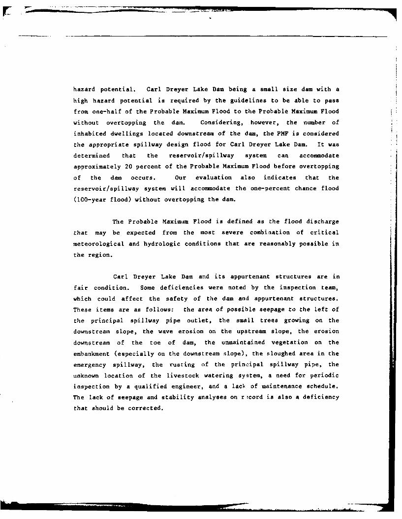
hazard potential. Carl Dreyer Lake Dam being a small size dam with a
high hazard potential is required by the guidelines to be able to pass
from one-half of the Probable Maximum Flood to the Probable Maximum Flood
without overtopping the dam. Considering, however, the number of
inhabited dwellings located downstream of the dam, the PMF is considered
the appropriate spillway design flood for Carl Dreyer Lake Dam. It was
determined that the reservoir/spillway system can accommodate
approximately 20 percent of the Probable Maximum Flood before overtopping
of the dam occurs. Our evaluation also indicates that the
reservoir/spillway system will accommodate the one-percent chance flood
(100-year flood) without overtopping the dam.
The Probable Maximum Flood is defined as the flood discharge
that may be expected from the most severe combiaation of critical
meteorological and hydrologic conditions that are reasonably possible in
the region.
Carl Dreyer Lake Dam and its appurtenant structures are in
fair condition. Some deficiencies were noted by the inspection team,
which could affect the safety of the dam and appurtenant structures.
These items are as follows: the area of possible seepage to the left of
the principal spillway pipe outlet, the small trees growing on the
downstream slope, the wave erosion on the upstream slope, the erosion
downstream of the toe of dam, the unmaintained vegetation on the
embankment (especially on the downstream slope), the sloughed area in the
emergency spillway, the rusting of the principal spillway pipe, the
unknown location of the livestock watering system, a need for periodic
inspection by a qualified engineer, and a lacI of maintenance schedule.
The lack of seepage and stability analyses on rtcord is also a deficiency
that should be corrected.

It is recommended that the owner take immediate action to
correct the inadequacy of the reservoir/spillway system to pass the
Probable Maximum Flood. Remedial measures should also be taken to
correct or to control the other deficiencies described above in the near
future.
Walter G. Shifrin, P.E.
~/ WALTER 0..IG. SHIFRIN
E-883

.
(I-
cz

NATIONAL DAM SAFETY PROGRAM
CARL DREYER LAKE DAM, ID. No. 10158
TABLE OF CONTENTS
Sect. No. Title Page
SECTION 1 PROJECT INFORMATION. ........ 1
1.1 General .... ........... 1
1.2 Description of Project . . .. 2
1.3 Pertinent Data .... ........ 7
SECTION 2 ENGINEERING DATA .... ......... 10
2.1 Design .... ............. 10
2.2 Construction .. ......... . .11
2.3 Operation ... .......... . 12
2.4 Evaluation .......... 12
SECTION 3 VISUAL INSPECTION .. ......... ... 14
3.1 FindLngs ... ........... ... 14
3.2 Evaluation. . . . . . . . . . 20
t JI

TABLE OF CONTENTS
(Continued)
Sect. No. Title Page
SECTION 4 OPERATION PROCEDURES . . . . . . 22
4.1 Procedures ...... . . . 22
4.2 Maintenance of Dam . . . . . 22
4.3 Maintenance of Operating
Facilities ... ....... . . 22
4.4 Description of Any Warning
System in Effect ......... 23
4.5 Evaluation . . . . . . . ... 23
SECTION 5 HYDRAULIC/HYDROLOGIC . . . . . . . 24
5.1 Evaluation of Features .... 24
SECTION 6 STRUCTURAL STABILITY ........... ... 28
6.1 Evaluation of Structural
Stability .............. ... 28
SECTION 7 ASSESSMENT/REMEDIAL MEASURES. . . . 30
7.1 Dam Assessment .......... ... 30
7.2 Remedial Measures. . . . . . . 32

TABLE OF CONTENTS
(Continued)
LIST OF PLATES
Plate No.
LOCATION MAP.........................1
PLAN AND ELEVATION OF DAM....................2
EMBANKMENT SECTION AND SPILLWAY PROFILE. .......... 3
SCS DESIGN DRAWINGS AND FLOOR ROUTING CALCULATIONS ... 4-5
GEOLOGIC MAP.........................6-7
SEISMIC ZONE MAP ........................ 8
APPENDICES
APPENDIX A - PHOTOGRAPHS
APPENDIX B - HYDROLOGIC AND HYDRAULIC COMPUTATIONS
PHASE I INSPECTION REPORTNATIONAL DAM SAFETY PROGRAM
CARL DREYER LAKE DAM, Missouri Inv. No. 10158
SECTION 1: PROJECT INFORMATION
1. 1 General
a. Authority
The Dam Inspection Act, Public Law 92-367 of
August, 1972, authorizes the Secretary of the Army, through the
Corps of Engineers, to initiate a national program of dam inspec-
tions. Inspection for Carl Dreyer Lake Dam was carried out under
Contract DACW 43-80-C-0094 between the Department of the Army,
St. Louis District, Corps of Engineers, and the engineering firms of
Consoer, Townsend & Associates, Ltd., and PRC Engineering Consul-
tants, Inc. (A Joint Venture), of St. Louis, Missouri.
b. Purpose of Inspection
The visual inspection of Carl Dreyer Lake Dam was made on
June 5, 1980. The purpose of the inspection was to make a general
assessment regarding the structural integrity and operational
adequacy of the dam embankment and its appurtenant structures.

c. Scope of Report
This report summarizes available pertinent data relating
to the project, provides a summary of visual observations made
during the field inspection, gives an assessment of hydrologic and
hydraulic conditions at the site, presents an evaluation of the
structural adequacy of the various project features and appraises
the general condition of the dam with respect to safety.
Subsurface investigations, laboratory testing and de-
tailed analyses were not within the scope of this study. No war-
ranty as to the absolute safety of the project features is implied
by the conclusions presented in this report.
It should be noted in this re )ort that reference to the
left or right abutments is viewed as looking downstream. Where left
abutment or left side of the dam is used in this report, this also
refers to the east abutment or side, and right to the west abutment
or side.
d. Evaluation Criteria
The inspection and evaluation of the dam is performed in
accordance with the U.S. Army Corps of Engineers "Engineer Regula-
tion No. 1110-2-106" and additional guidelines furnished by the St.
Louis District office of the Corps of Engineers for Phase 1 Dam
Inspections.
1.2 Description of the Project
a. Description of Dam and Appurtenances
The following description is based upon observations and
measurements made during the visual inspection and conversations
with Mr. Bill Dreyer, the owner's representative. Two Soil Conser-
vation Service (S.C.S.) design drawings were located and are pre-
-2-

sented in this report (see Plates 4 and 5). Discrepancies between
our field notes and the design drawings were found and are noted in
Section 2.1.
The dam is a homogeneous, rolled, earthfill structure
between earth abutments, and consists of two straight portions of
embankment angled at approximately 32 degrees to each other. A plan
and elevation of the dam are shown on Plate 2 and Photos 1 through 3
show views of the dam. The major portion of the embankment has a
bearing of approximately N 670 E and an axis length of 344 feet
between the right abutment and the point of intersection of the two
axes. The other portion of the dam has a bearing of approximately N
350 E and a length of 146 feet between the point of intersection of
the two axes and the emergency spillway. The top of dam has a total
length of 490 feet between the emergency spillway and the right
abutment. The change in the alignment of the dam agrees with the
design drawing. The top of dam is 15 feet wide and was measured as
level with an elevation of 808.5 feet above mean sea level (M.S.L.).
The maximum structural height of the dam was measured as 34 feet.
The upstream slope above the water surface varied between 1 vertical
to 2.5 horizontal (IV to 2.5H). The downstream slope was measured
to be 1V to 1.75H. According to Mr. Dreyer, a core trench was
constructed parallel to the dam axis, which agrees with the design
drawings.
The dam was constructed with a double spillway scheme;
the first is considered the principal spillway and operates as a
closed conduit when flowing full, and the second is considered the
emergency spillway and operates as an open channel.
The principal spillway was constructed from approximately
110 feet of welded steel pipe with a 5/16-inch wall thickness and
19-inch inside diameter. The inlet end of the pipe has been cut on
an angle of approximately 35 degrees leaving the top of the pipe
protruding over the bottom; also, there is a 30-inch diameter metal
hood welded to the top of the inlet pipe (see Photo 5). It was laid
-3-

through the embankment, 292 feet to the right of the emergency
spillway, on an approximately 30 percent slope. The entrance allows
flow directly into the pipe. The principal spillway crest elevation
is an assumed 804 feet above M.S.L. Water flowing over the crest to
the outlet end of the spillway pipe enters a discharge pool before
reaching the downstream channel (see Photo 6). According to the
drawings received by the inspection team, two 6-foot by 6-foot metal
cut off collars were installed during construction, and the pipe
that was used for the spillway conduit was bituminous coated.
The emergency spillway was constructed into the left
abutment area of the dam with a discharge channel that directs the
excess flows in a perpendicular direction away from the dam; after
flowing past the crest, the water enters a wide swale type channel
before being directed into a wooded area (see Photo 7). The over-
flow eventually reaches the downstream channel. The emergency
spillway crest operates as a trapezoidal open channel with a top
width of 58 feet, a bottom width of 29 feet, and side slopes of
approximately lV to 8H. The slope of the approach to the emergency
spillway crest is 14 percent, the crest itself is level for a
distance 30 feet, and the discharge channel begins with a slope of
approximately 1 percent which then steepens to a slope of almost 3
percent (see Plate 3). The elevation of the crest is about 807.2
feet above M.S.L., which makes it about 3.2 feet above the crest of
the principal spillway and about 1.3 feet below the top of dam.
No low level outlet or outlet works were found for this
dam. However, according to Mr. Dreyer, a 1-1/2-inch diameter pipe
was provided through the embankment for use as a livestock watering
system. The system was capped at the downstream end. The location
of the pipe is unknown.
-4-

b. Location
Carl Dreyer Lake Dam is located in Montgomery County of
the State of Missouri on an unnamed tributary of the Smith Branch of
Clear Fork Creek, which flows into the Loutre River. The dam is
located approximately 3 miles northwest of the town of New Florence
in the northwest corner of Section 16 of Range 5 West, Township 48
North as shown on the New Florence, Missouri Quadrangle (7.5 minute
series) sheet.
c. Size Classification
Carl Dreyer Lake Dam impounds less than 1,000 acre-feet
but more than 50 acre-feet; which classifies it as a "small" dam.
The maximum structural height is less than 40 feet and greater than
25 feet, which also leads to the classification of a "small" dam.
The size classification is determined by either storage or the
height, whichever gives the larger size category. Therefore, the
size classification is determined to fall within the "small" cate-
gory according to the "Engineer Regulation No. 1110-2-106, Appendix
D" by the U.S. Department of the Army, Office of the Chief Engineer.
d. Hazard Classification
The dam has been classified as having a "high" hazard
potential in the National Inventory of Dams, on the basis that in
the event of failure of the dam or its appurtenances, excessive
damage could occur to downstream property together with the possi-
bility of the loss of life. Based upon a visual inspection of the
downstream area, our findings concur with this classification.
There are four dwellings and two buildings within the estimate
damage zone, which extends approximately four miles downstream of
the dam (see Photo 10).
-5-

e. Ownership
Carl Dreyer Lake Dam is owned privately by Dr. and Mrs.
Carl J. Dreyer. The mailing address is as follows: Dr. and Mrs.
Carl J. Dreyer, 45 Glen Road, Webster Groves, Missouri, 63119.
f. Purpose of Dam
The purpose of the dam is to impound water for recrea-
tional use as a private lake.
g. Design and Construction History
Carl Dreyer Lake Dam was designed by the Department of
Agriculture, Soil Conservation Service, in June of 1961. The design
engineer was Mr. Bernard G. Browning. Mr. Ralph Kelsick Jr. was the
owner of the property when the plans for the dam were prepared, but
the dam was built after Dr. Dreyer purchased the property from Mr.
Ralph Kelsick Jr. According to Dr. Dreyer, the dam was constructed
between January and July of 1969 by Mr. Ray Windsor of Williamsburg,
Missouri.
h. Normal Operational Procedures
Normal procedure for this dam is to allow the reservoir
to remain as full as possible. The water level is controlled by
rainfall, runoff, evaporation, and the crest of the principal
spillway.
-6-

1.3 Pertinent Data
a. Drainage Area (square miles): ..... 0.31
b. Discharge at Damsite
Estimated experienced maximum flood (cfs): . . . .. 76
Estimated ungated spillway capacity withreservoir at top of dam elevation (cfs): . . . . . . . 173
c. Elevation (Feet above M.S.L.)
Top of dam: .................. * . . . . . . 808.5
Spillway crest:
Principal Spillway . . . ........ 804.0(Assumed)
Emergency Spillvay . . . . . . . 807.2
Normal Pool: . ................ . . . 804.0
Maximum Experienced Pool:. . . . . . . . . . . . . . . 807.7
Observed Pool: ................... .. . . 804.0
d. Reservoir
Length of pool with water surfaceat top of dam elevation (feet): ........... . . . . 1600
e. Storage (Acre-Feet)
Top of dam: ..... ..................... . 141
Spillway crest:
Principal Spillway .......... . . . . . 78
Emergency Spillway . . . . . . . . . . . 119Normal Pool: .. .. .. 0.. .. .. .. .. .... 78
Maximum Experienced Pool: . . . . . . . . . . . . . . 127
Observed Pool: . . . . . . ....... . . . . . . . 78
f. Reservoir Surfaces (Acres)
Top of dam: . . . . . . . . . . . . . . . . . .... 18
Spillway crest:
-7-

Principal Spillway ....... . . . . . 1
Emergency Spillway . . . . . . . . . . . 15
Maximum Experienced Pool: .. ....... .. o.. .. ... 16
ObservedPool: .oo. .... ......... . 15
g. Dam
Type:. .. ........................ Rolled, Earthfill
Length:.....o.......... ..... 490 feet
Structural Height: . .. .. .. ... 34 feet
Hydraulic Height:. . o o . . . . 34 feet
Top width: . . . .. . . . . l 5 feet
Side slopes:
Do v n s t r e amo . l V to lo75H
Upstream. .. ...... . .o o- Varied from 1V to 2.5H to near
vertical (Above the water surface)
Zoning:........... o . Homogeneous
Impervious core:............ NA
Cutoff:. . . . . . .... .. .. A core trench with an 8-foot
bottom width and side slopes
of 1H to 1V (According to
design drawing and Mr. Dreyer)o
Grout curtain:........ . None
Freeboard above normal
reservoir level: . . . . . . . . . .. 4.5 feet
Volume:o. . .. .. ... . . . . . .. 14,385 cu-yds. (According to
the design drawings)
h. Diversion and Regulating Tunnel - o . . . . None
i. Spillway
Type:
Principal Spillway ... ...... Pipe, uncontrolled
Emergency Spillway . . . . . . . . Earthcut channel, uncontrolled
Length of crest:
Principal Spillway . . . .NA, 19-inch I.D. pipe

Emergency Spillway . . . . . . . . 29 feet
Crest Elevation (feet above MSL):
Principal Spillway .. ....... 804.0
Emergency Spillway. ......... 807.2
J. Regulating Outlets
Type: .. ............. . . .. 1-1/2-inch diameter livestock
watering system, assumed to be
abandoned. (Reportedly)
Location: .. ......... ..... Unknown
Length: .. ........ .. .. .... Unknown
Closure: . . . . . . .. .. .. ... Cap on downstream end
Maximum Capacity: .. . . . .. .. . .Unknown
-9-

SECTION 2: ENGINEERING DATA
2.1 Design
Two design drawings with some construction notes on them were
obtained from the Department of Agriculture, Soil Conservation Service,
and are included as part of this report (see Plates 4 and 5). The
drawings were prepared in June of 1961 by the Department of Agriculture,
Soil Conservation Service. Floou routing calculations for the principal
and emergency spillways are included as parL of the drawings (see Plate
5).
Numerous discrepancies were found between our field notes and
the design drawings and are mentioned below:
1. The top thickness of the dam according to the draw-
ings, was 11 feet and field measurements show it to be 15 feet.
2. The total length of the embakment, according to the
drawings, was approximately 545 feet between the right abutment and
the emergency spillway and the field measured distance was 490 feet.
3. The respective distances of the two lengths of
embankment also differed from that shown on the plans. The major
portion, according to the drawings, was 372 feet but was field
measured as 344 feet. The other portion was designed to be 173 feet
but was field measured as 146 feet.
4. According to the drawings, the maximum structural
height was between 27 and 24.8 feet, depending upon the anticipated
settlement. Field measurements show the structural height to be 34
feet.
5. The upstream and downstream slopes according to the
design drawings were IV to 3H and IV to 2H, respectively; our
measurements show them to be IV to 2.5H and IV to 1.75H, respec-
tively. However, the upstream slope was measured only above the
normal water surface, which may or may not reflect the way the
upstream slope was actually constructed due to the observed damage
-10-

(see Section 3.1b) to the upper portion of the slope
6. The principal spillway pipe, according to the draw-
ings, was originally designed using a 21-inch diameter corrugated
metal pipe. According to the construction notes on the drawings,
the pipe was changed to a 20-inch inside diameter steel pipe. Our
inspection shows that a 19-inch inside diameter welded steel pipe
was used. Originally the pipe was to be bituminous coated, however,
no evidence of this could be observed in the field.
7. The location of the principal spillway pipe, accord-
ing to the design drawings, was 215 feet to the left of the right
abutment. Field measurements show this distance as 198 feet.
8. The emergency spillway crest should be 2.2 feet above
the principal spillway crest and 1.6 feet below the top of dam, if
built according to the drawings; field measurements indicate that
these distances are 3.2 feet and 1.3 feet, respectively. The
drawings also use a 44-foot crest length for the emergency spillway,
whereas a 29-foot length was measured in the field.
2.2 Construction
No data are available concerning the construction of the dam
and appurtenant structures, other than the design drawings with the
construction notes on them, and the information obtained from by tele-
phone Dr. Dreyer (described below). Dr. Dreyer made available six slides
that were taken during the construction of the dam. The slides are
primarily general overviews of the reservoir and dam embankment and are
not included in this report.
According to Dr. Dreyer, the compaction of the embankment was
achieved by the activity of the earthmoving equipment across the embank-
ment; no compaction control was employed and periodic inspections of the
damsite during the construction of the dam were made by the Soil Conser-
vation Service (No record of the visits were found). A core trench was
excavated parallel to the dam axis but not into bedrock, which corre-
sponds to what is shown on the design drawings. The trench, according to
Dr. Dreyer, was excavated to an unknown depth into a suitable hard clay
-11-

(firebrick clay) foundation. The trench has a bottom width of 8 feet and
side slopes of IV to 1H, according to the design drawings.
2.3 Operation
No operational records are available for Carl Dreyer Lake Dam.
2.4 Evaluation
a. Availability
The availability of engineering data is good. The data
consist of the design drawings and flood routing calculations
mentioned in Section 2.1, a soil survey of Montgomery County con-
ducted by the Soil Conservation Service, State Geological Maps, and
U.S.G.S. Quadrangle Sheets.
b. Adequacy
The conclusions presented in this report are based upon
field measurements, the available engineering data, past perfor-
mance, and present condition of the dam. The available data and the
field measurements are adequate enough to evaluate the hydraulic and
hydrologic capabilities of the dam and its appurtenant structures.
Seepage and stability analyses comparable to the requirements of the
"Recommended Guidelines for Safety Inspection of Dams" were not
available, which is considered a deficiency. These seepage and
stability analyacs should be performed for appropriate loading
conditions (including earthquake loads) and made a matter of record.
-12-
c. Validity
A set of design drawings was available for review. From
field measurements, the dam appears to have been basically con-
structed according to the available drawings; however, the drawings
cannot be considered "As-built" drawings due to the discrepancies
described in Section 2.1. The discrepancies between the design
drawings and the field notes are considered to be minor. The only
discrepancies that might have some affect on the safety of the dam
and appurtenant structures would be the more steeply constructed
slopes of the embankment and the smaller bottom width used in
construction of the emergency spillway.
-13-

I! SECTION 3: VISUAL INSPECTION
3.1 Findings
a. General
A visual inspection of the Carl Dreyer Lake Dam was made
on June 5, 1980. The following persons were present during the
inspection:
Name Affiliation Disciplines
Mark Haynes, P.E. PRC Engineering Consultants, Inc. Proj ect Engineer,Soils and Mechanical
Jerry Kenny PRC Engineering Consultants, Inc. Hydraulics andHydrology
Robert McLaughlin, PRC Engineering Consultants, Inc. CivilP. E.
Raz Quraishi, PRC Engineering Consultants, Inc. GeologyR.P.G.
John Lauth, P.E. Consoer, Townsend & Assoc., Ltd. Civil andStructural
Bill Dreyer Owner's Representative
Specific observations are discussed below.
-14-

The overall condition of the dam appears to be fair.
Some items of concern were observed and are described below.
The top of dam appears to be adequately protected against
surface erosion by a well-maintained grass cover and is occasionally
used as a farm access road (see Photo 2). No tire ruts or depres-
sions, which are sometimes associated with vehicular traffic across
earthen structures, were observed. No depressions or cracks indica-
ting a settlement of the embankment were observed. No significant
deviation in the vertical or horizontal alignment, other than the
change in direction of the alignment was apparent. According to Mr.
Dreyer, the dam has never been overtopped and no evidence indicating
the contrary was observed.
The upstream slope was originally constructed with no
riprap protection. According to Mr. Dreyer, riprap was placed on
the upstream slope between 1970 and 1972. Evidence of the riprap
was observed on the slope; however, only a small amount of riprap
remained near the water surface, which did not appear to provide
adequate protection against wave action. Considerable wave erosion
of the slope near the normal water surface level has occurred (see
Photo 4). In a few areas, the scarps due to the wave erosion
extended to the top of dam, and the slope has steepened to near
vertical. Undercutting of the slope was observed, which indicates
future sloughing of the slope is possible. Canary reed grass was
also planted near the water surface to prevent further erosion of
the slope. The upper portion of the slope appeared to be adequately
protected against surface erosion by an unmaintained grass cover
(see Photo I). No bulges, depressions or cracks indicating an
instability of the embankment or foundation were observed on the
slope.
.- 15-

The downstream slope was covered by a heavy growth of
vegetation and small trees (see Photo 3). The vegetation hampered a
comprehensive inspection of the slope. On the day of the inspec-
tion, Mr. Dreyer was in the procer i of removing the trees from the
slope. Most of the trees measured 3 inches in diameter with one
measuring 6 inches in diameter. Standing water and an area of boggy
ground was observed just downstream of the toe of dam and to the
left of the principal spillway outiet. The area extended approxi-
mately 100 feet to the left of the okutlet. Ic was undetermined
whether :he standing water was due to seepage through the emwankment
or found ition or due to a rt.cent rainstorm. No measurable fiow,
boils, or evidence of piping of the embankment material were ob-
served. One small erosion gulLy was seen downstream of the toe on
the left side of the dam. No bulges, depressions or cracks were
apparent on the slope.
Both abutments slope gently upward from the top of dam.
No instabilities, seepage, or erosion were observed on either
abutment.
No evidence of burrowing animals was apparent on either
the embankment or abutments.
c. Project Geology and Soils
(1) Project Geology
The damsite is located on an unnamed tributary of the
Smith Branch of Clear Fork Creek in the Dissected Till Plains
Section of the central Lowland Physiographic Province. Loess-
mantled Kansas drift covers the surface of most of the Dissected
Till Plains Section. This section is distinguished from the Young
Drift Section to the north and from the Till Plains on the east by
the stage it has reached in the post-glacial erosion cycle. Broadly
generalized, this section is a nearly flat till plain submature to
mature in its erosion cycle.
-16-

The topography at the damsite is flat to rolling with IT-
shaped valleys. Elevation of the g-ound surface ranges from 820
feet above M.S.L. at the damsite to 850 feet above M.S.L. nearly 0.5
miles northeast of the damsite. The reservoir slopes are in the
range of 150 from the horizontal at the western and northern sides,
and between 80 and 300 from the horizontal at the northeast side of
the reservoir. The area near the damsite is covered with slope wash
deposits of glacial-fluvial and loess origins consisting of mottled
reddish-brown to gray, silty clay.
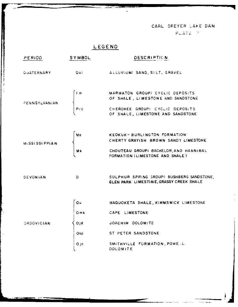
The regional bedrock geology beneath the glacial outwash
deposits in the damsite area, as shown on Geologic Map of Missouri
(1979) (see Plate 6), consists of the Pennsyslvanian Marmaton-
Cherokee Group rocks (cyclic deposits of shale, limestone and
sandstone), Mississippian Burlington Limestone (cherty, grayish
brown, sandy limestone), the Mississippian Chouteau Group, the
Devonian Sulphur Springs Group (Bushberg Sandstone, Glen Park
Limestone, Grassy Creek Shale), and Ordovician rocks consisting of
Maquoketa Shale, Kimmswick Limestone, Cape Limestone, Joachim
Dolomite, St. Peter Sandstone, and Powell Dolomite. The predominent
bedrock near the damsite underlying the glacial-fluvial deposits are
the Pennsylvanian cyclic deposits of shale, limestone, and sandstone
of the Marmaton-Cherokee Group and Mississippian Burlington Lime-
stone. Inlet and outlet areas of the unnamed tributary of the Smith
Branch exhibit quaternary alluvium.
No faults have been identified in the vicinity of the
damsite. The closest trace of a fault to the damsite is the Mineola
Fault nearly 4 miles southwest of the damsite. The Mineola fault
had its last movement in post-Early Ordovician time. Thus, the
fault has no effect on the damsite.
Carl Dreyer Lake Dam consists of a homogenous earthfill
embankment, a metallic principal spillway pipe located at the mid-
section of the embankment, and an emergency spillway located near
the left abutment of the embankment. Based on the data from the
-17- I

available construction drawings and the visual inspection, the
embankment probably rests on the glacial deposits of yellowish
brown, silty clay. Available data indicates that a pre-construction
exploratory boring of 5 feet was drilled along the axis of the dam
near the original stream channel. This boring was terminated in
clay. The emergency spillway was cut into the glacial-fluvial
deposits of the left abutment.
(2) Project Soils
According to the "Soil Survey of Montgomery and Warren
Counties, Missouri" published by the Soil Conservation Service in
1978, the soils in the general area of the dam belong to the
Keswick-Lindley association. The soils at the damsite consist of
the Keswick silt loam and clay loam, the Sharon silt loam and the
Lindley loam. These soils are basically formed from glacial till
and alluvium. The Keswick clay loam is generally quite susceptible
to erosion. If the Keswick soil was used in the embankment, the
potential of failure of the embankment would be increased due to
erosion during overtopping.
Materials removed from the upstream and downstream slopes
of the embankment appeared to be a light brown, silty clay with some
fine to coarse sand. Based upon the Unified Soil Classification
System, the soil would probably be classified as a CL. This is an
impervious soil type which generally has the following characteris-
tics: a coefficient of permeability less than 1.0 foot per year,
medium shear strength, and a high resistance to piping.
-18-

d. Appurtenant Structures
(1) Principal Spillway
The principal spillway appears to be in fairly good
shape, both at the inlet end and at the outlet end. However, there
does not seem to be any kind of a protective coating applied to the
pipe, and some resultant rust and corrosion are presently occurring
(see Photos 5 and 6).
(2) Emergency Spillway
The emergency spillway approach area contains a sloughed
section and resultant erosion; also, some reeds are beginning to
appear in front of the inlet area (see Photo 7).
(3) Outlet Works
No low level outlets or outlet works were provided for
this dam. The only operating facility at the damsite is, re-
portedly, a 1-1/2-inch diameter pipe used to supply water to
livestock downstream. The location of the livestock watering system
was unknown and the system is assumed abandoned.
e. Reservoir Area
The reservoir water surface elevation at the time of the
inspection was assumed at 804 feet above M.S.L.
The surface area of the reservoir at normal water level
is about 11 acres. The rim appeared to be stable with no erosional
problems observed. The land around the reservoir slopes gently
upward from the rim and is grass and tree covered (see Photo 9).
One house, owned by Dr. Carl Dreyer, is built on the right side of
the reservoir area.
-19-

f. Downstream Channel
The downstream channel is undefined and obstructed with
trees and large vegetation (see Photo 8). The streambed is very
narrow and shallow, and the floodplain outside of the streambed is
fairly wide.
3.2 Evaluation
The visual inspection uncovered nothing of a consequential
nature which would require immediate remedial action. However, the
following conditions were observed which could adversely affect the dam
in the near future.
1. The possible seepage, indicated by standing water and
boggy ground in an area downstream of the toe and to the left of the
principal spillway outlet, could affect the structural stability of the
dam. It was undetermined if the condition was due to seepage or a recent
rainstorm. If it was indeed due to seepage and the rate of seepage were
to increase, it is possible that the seepage could transport soil par-
ticles. This could cause piping of embankment material which could lead
to an eventual failure of the embankment.
2. The small trees observed on the downstream slope pose a
potential danger to the safety of the dam depending upon the extent of
the root system. On the day of the inspection, Mr. Dreyer was in the
process of removing the trees from the slope. The roots of large trees
present possible paths for piping through the embankment. The root
systems can also do damage to the embankment from being uprooted by a
storm.
3. The wave erosion on the upstream slope does not appear to
affect the stability of the dam in its present condition. Corrective
measures have been taken to control the erosion, but they appear to be
ineffective. Continual erosion of the slope can only be detrimental to
the stability of the dam.
-20-

4. The erosion downstream of the toe does not pose a danger
to the stability of the embankment in its present condition. Neverthe-
less, continual erosion could endanger the stability of the dam.
5. The growth of vegetation on the embankment should be
properly maintained. A tall, dense growth of vegetation on the embank-
ment hinders a comprehensive inspection of the dam and potential problems
could go undetected.
6. The rust on the principal spillway pipe does not appear
severe enough to cause problems at this time.
7. The sloughed area of the emergency spillway induces a
turbulent condition when excess floodwaters flow over it; this in turn
could cause the situation to worsen, by exposing more of the emergency
spillway inlet area to surface erosion. If the reeds in front of the
emergency spillway inlet continue to grow there, an obstructed entrance
could eventually be created.
8. The livestock watering system, even though it is presumed
abandoned, could be a source of serious problems. A seepage path could
occur along the pipe, which could cause piping of the embankment material
and lead to an eventual failure of the dam.
-21-

SECTION 4: OPERATIONAL PROCEDURES
4.1 Procedures
There are no specific procedures set forth for the operation Iof Carl Dreyer Lake Dam. The water level below the principal spillway
crest is allowed to remain as high as possible, and is controlled by
rainfall, runoff, evaporation, and unregulated spillway releases. The
only operating facility at the damsite is a livestock watering system,
which appears to be abandoned.
4.2 Maintenance of Dam
The dam is maintained by Dr. Carl Dreyer, the owner, and Mr.
Bill Dreyer. Mr. Bill Dreyer was in the process of removing the small
trees from the downstream slope on the day of the inspection. The top of
dam and the emergency spillway are mowed periodically. However, the
upstream and downstream slopes have received little or no maintenance
and, consequently, dense vegetation and trees have grown up on the
downstream slope. Riprap has been added to the upstream slope near the
water's edge to prevent wave erosion. Nevertheless, the riprap is
inadequate and continual erosion of the slope is evident.
4.3 Maintenance of Operating Facilities
There are no operable facilities associated with the dam,
other than the assumed abandoned livestock watering system.
-22-

4.4 Description of Any Warning System in Effect
The inspection team is not aware of any existing warning
system consisting of any electrical warning systems or manual notifica-
tion warning plans in effect for this dam.
4.5 Evaluation
The maintenance at Carl Dreyer Lake Dam appears to be inade-
quate at this time, however, the dam does not appear to be neglected.
The remedial measures described in Section 7 should be undertaken to
improve the condition of the dam.
-23-

SECTION 5: HYDRAULIC/HYDROLOGIC
5.1 Evaluation of Features
a. Design
The watershed area of the Carl Dreyer Lake Dam upstream
from the dam axis consists of approximately 200.5 acres. The
watershed area is mostly crop land or wooded areas with some pasture
land. Land gradients in the watershed average roughly 2 pecent.
The Carl Dreyer Lake Dam is located on an unnamed tributary of the
Smith Branch of Clear Fork Creek. The reservoir behind the dam is
about 0.3 miles upstream from the confluence of the unnamed tribu-
tary and the Smith Branch. The watershed, at its longest arm, is
approximately 0.8 miles long. A drainage map showing the watershed
and the downstram hazard zone is presented as Plate I in Appendix B.
Evaluation of the hydraulic and hydrologic features of
Carl Dreyer Lake Dam was based upon criteria set forth in the Corps
of Engineers' "Engineer Regulation No. 1110-2-106" and additional
guidance provided by the St. Louis District of the Corps of Engi-
neers. The Probable Maximum Flood (PMF) was calculated from the
Probable Maximum Precipitation (PMP) using the methods outlined in
the U.S. Weather Bureau Publication, Hydrometeorlogical Report No.
33. The probable maximum storm duration was set at 24 hours, and
storm rainfall distribution was based upon criteria given in the
Corps of Engineers' EM 1110-2-1411 (Standard Project Storm). The
Soil Conservation Service (SCS) method was used for deriving the
unit hydrograph, utilizing the Corps of Engineers' computer program
EEC-i (Dam Safety Version). The unit hydrograph parameters are
presented in Appendix B. The SCS method also was used for determin-
ing the loss rate. The hydrologic soil group of the watershed was
determined by use of published soil maps. The hydrologic soil group
of the watershed and the SCS curve number are presented in Appendix
-24-

B. The curve number, unit hydrograph parameters, the PMP index
rainfall and the percentages for various durations were direct input
to the HEC-1 (Dam Safety Version) computer program to obtain the PMF
hydrograph. The computed peak inflows of the PMF and the one-half
PMF are 3,527 cfs and 1,763 cfs, respectively.
Both the PMF and the one-half PMF inflow hydrographs were
routed through the reservoir by the Modified Puls Method, also
utilizing the HEC-I (Dam Safety Version) computer program. An
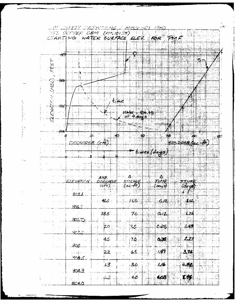
antecedent storm of 50 percent of the PMF, preceded the PMF and an
antecedent storm of 25 percent of the PMF preceded the one-half PMF,
each by four days. The reservoir was assumed at the mean annual
high water level at the beginning of the antecedent storm. The mean
annual high water level for Carl Dreyer Lake Dam was estimated to be
at the crest of the principal spillway. The antecedent storm of 50
percent of the PMF, when routed through the reservoir, will leave
the reservoir at an elevation of approximately 804.45 at the end of
the four-day period. Thus, the reservoir was assumed to be at the
level of 804.45 at the start of the routing computation for the PMF
and PMF ratio floods other than the one-half PMF. The reservoir was
assumed to be at the crest of the principal spillway at the start of
the routing computation for the one-half PMF. The peak outflow
discharges for the PMF and the one-half PMF are 3,180 and 1,559 cfs,
respectively. Both the PMF and the one-half PMF, when routed
through the reservoir, resulted in overtopping of the dam.
The sizes of physical features utilized to develop the
stage-outflow relation for the spillway and overtopping of the dam
were taken from field notes and sketches prepared during the flpld
inspection. The reservoir elevation-area data were obtained from
the U.S.G.S. New Florence, Missouri Quadrangle topographic map (7.5
minute series). The reservoir elevation-area curve and the spillway
and overtop rating curve are presented as Plates 2 and 3, respec-
tively, in Appendix B.
-25-
From the standpoint of dam safety, the hydrologic design
of a dam must aim at avoiding overtopping. Overtopping is espe-
cially dangerous for an earth dam because of its erodable character-
istics. The safe hydrologic design of an embankment dam requires a
spillway discharge capability combined with an embankment height
that can handle a very large and exceedingly rare flood without
overtopping the dam.
The Corps of Engineers designs dams to safely pass the
Probable Maximum Flood that could be generated from the dam's
watershed. This is the generally accepted criterion for major dams
throughout the world and is the standard for dam safety where
overtopping would pose any threat to human life. Accordingly, the
hydrologic requirement for safety for this dam is the capability to
pass the Probable Maximum Flood without overtopping the dam.
b. Experience Data
It is believed that records of reservoir stage or spill-
way discharge are not maintained for this site. However, according
to Mr. Dreyer, the maximum observed reservoir level was approxi-
mately six inches over the crest of the emergency spillway.
c. Visual Observations
Observations made of the spillways during the visual
inspection are discussed in Section 3.1d and evaluated in Section
3.2.
d. Overtopping Potential
As indicated in Section 5.1a, both the Probable Maximum
Flood and the one-half Probable Maximum Flood when routed through
the reservcir, resulted in overtopping of the dam. The peak outflow
discharges for the PMF and the one-half PMF are 3,180 and 1,559 cfs,
respectively. The maximum capacity of the spillway just before
-26-

overtopping the dam is 173 cfs. The PMF overtopped the dam by 1.41
feet and the one-half PMF overtopped the dam by 0.82 feet. The
total duration of flow over the top of dam is 6.25 hours during the
occurrence of the PMF and 4.17 hours during the occurrence of the
one-half PMF. The spillway/reservoir system of Carl Dreyer Lake Dam
is capable of accommodating a flood equal to approximately 20
percent of the PMF just before overtopping the dam. The reser-
voir/spillway system of Carl Dreyer Lake Dam will accommodate the
one-percent chance flood (100-year flood) without overtopping the
dam.
The failure of the dam could ciuse extensive damage to
the property downstream of the dam and possible loss of life. The
estimated damage zone extends approximately four miles downstream of
the dam. There are four dwellings and two buildings within the
damage zone.
-27-

SECTION 6: STRUCTURAL STABILITY
6.1 Evaluation of Structural Stability
a. Visual Observations
There were no major signs of settlement or distress
observed on the embankment or foundation during the visual inspec-
tion. The possible seepage observed to the left of the principal
spillway outlet does not appear to affect the stability of the dam
in its present condition. Nevertheless, any increase in the condi-
tion of the seepage can only be detrimental to the embankment. The
erosion due to wave- action on the upstream slope does not appear to
be serious enough to constitute an unsafe condition, and according
to Mr. Dreyer, steps have been taken to control the problem.
Nevertheless, the steps taken appear to be ineffective and future
sloughing is possible. The erosion downstream of the toe does not
affect the stability of the dam in its present condition. There was
no indication of past or present slope instability. In the absence
of seepage and stability analyses, no quantitative evaluation of the
structural stability can be made.
Both the principal spillway pipe and the emergency
spillway channel systems appeared to be structurally stable on the
day of the inspection.
b. Design and Construction Data
The design drawings and the flood routing calculations
were of limited use in the assessment of the structural stability of
the dam and appurtenant structures. Seepage and stability analyses
comparable to the requirements of the "Recommended Guidelines for
Safety Inspection of Dams" were not available. No embankment or
-28-

foundation soil parameters were available for carrying out a conven-
tional stability analysis on the embankment. No specifications
relating to the degree of embankment compaction were available for
use in a stability analysis.
c. Operating Records
No operating records are available relating to the
stability of the dam or its appurtenant structures. No regulated
outlet works were provided for the dam, other than the assumed,
abandoned livestock watering system. The water level on the day of
the visual inspection was at the crest of the principal spillway.
According to Mr. Dreyer, the reservoir remains close to full at all
times.
d. Post Construction Changes
No post construction changes are known to exist which
will affect the structural stability of the dam.
e. Seismic Stability
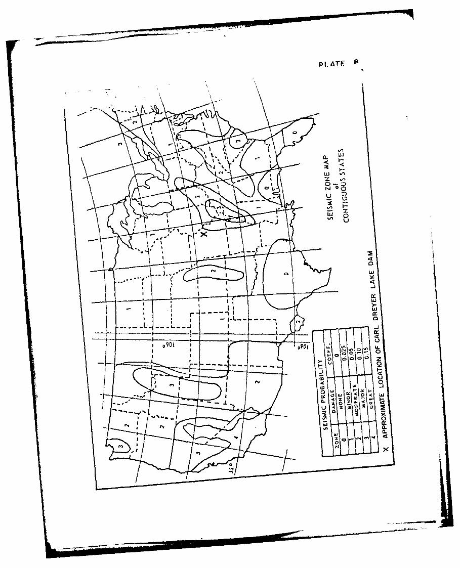
The dam is located in Seismic Zone 1 (see Plate 8), as
defined in "Recommended Guidelines for Safety Inspection of Dams"
prepared by the Corps of Engineers, and will not require a seismic
stability analysis. An earthquake of the magnitude which would be
expected in Seismic Zone 1 will not cause distress to a well de-
signed and constructed earth dam. Available literature indicates
that no active faults exist near the vicinity of the damsite.
-29-

SECTION 7: ASSESSMENT/REMEDIAL MEASURES
7.1 Dam Assessment
The assessment of the general condition of the dam is based
upon available data and visual inspections. Detailed investigations,
testing, and detailed computational evaluations are beyond the scope of a
Phase I investigation, however, the investigation is intended to identify
any need for such studies.
It should be realized that the reported condition of the dam
is based upon observations of field conditions at the time of inspection
along with data available to the inspection team.
It is also important to realize that the condition of a dam
depends upon numerous and constantly changing internal and external
factors, and is evolutionary in nature. It would be incorrect to assume
that the present condition of the dam will continue to represent the
condition of the dam at some point in the future. Only through continued
care and inspection can there be assurance that an unsafe condition could
be detected.
a. Safety
The spillway capacity of Carl Dreyer Lake Dam is found to
be "Seriously Inadequate". The spillway/reservoir system will
accommodate about 20 percent of the PMF without overtopping the dam.
The safety of the embankment will be in jeopardy if the dam is
overtopped. The embankment itself would be susceptible to erosion
due to the high velocity of flow on its downstream slope which could
lead to an eventual failure of the dam.
-30-
ii !
+ r i + - U° 1

The dam and appurtenant structures appeared to be in
fair condition. However, no quantitative evaluation of the struc-
tural safety of the embankment can be made in view of the absence of
seepage and stability analyses. The present embankment and appur-
tenant structures, however, have performed satisfactorily since
their construction without failure or evidence of instability,
according to Mr. Dreyer. Mr. Dreyer also stated that, the dam has
never been overtopped.
The safety of the dam can be improved if the deficiencies
described in Sections 3.2 and 6.1a and below are properly corrected
as described in Section 7.2b. The small trees on the downstream
slope could jeopardize the safety of the dam, if continued growth is
allowed.
b. Adequacy of Information
The conclusions presented in this report are based upon
field measurements, limited design drawings, past performance and
the present condition of the dam. The design drawings and the flood
routing calculations were of limited use in the assessment of the
overall safety of the dam and its appurtenant structures. Records of
the operation and maintenance of the dam were not available.
Seepage and stability analyses comparable to the requirements of the
"Recommended Guidelines for Safety Inspection of Dams" were also not
available, which is considered a deficiency.
-31-

C. Urgency
The remedial measures recommended in Paragraph 7.2 should
be accomplished within a reasonable period of time. The items
recommended in paragraph 7.2a should be pursued on a high priority
basis. The remedial measures should be accomplished under the
guidance of a professional engineer experienced in the design and
construction of earth dams.
d. Necessity for Phase IT Inspection
Based upon results of the Phase I inspection, assuming
the remedial measures recommended in Paragraph 7.2 are undertaken, a
Phase II inspection is not felt to be necessary.
7.2 Remedial Measures
a. Alternatives
There are several general options that may be considered to
reduce the possibility of dam failure or to diminish the harmful aspects
of such a failure. Some of these options are:
1. Increase the spillway capacity to pass the PMF without
overtopping the dam.
2. Increase the height of the dam enough to pass the PMF
without overtopping the dam; an investigation should be
done which also includes studying the effects on the
structural stability of the existing embankment. The
overtopping depth during the occurrence of the PMF, stated
in Section 5.1d, is not the required or recommended
increase in the height of the dam.
-32-
- I :' .. . I 3

3. A combination of I and 2 above.
b. 0 & M Procedures
I. The area of standing water and boggy ground to the left of
the principal spillway outlet should be further investi-
gated to determine if the condition is due to seepage or a
recent rainstorm. If the condition is indeed due to
seepage, the area should be monitored to detect any
changes in location, turbidity, and quantity of water.
Any changes should be investigated further and repairs
made as necessary.
2. All of the small trees on the downstream slope should be
removed from the slope and prevented from regrowing.
3. The erosion due to wave action on the upstream slope
should be properly repaired and adequately protected from
further damage.
4. The erosion downstream of the toe should be monitored and
properly repaired when deemed necessary.
5. The vegetation on the embankment, especially the vegeta-
tion on the downstream slope, should be properly main-
tained and an adequate vegetative cover retained on the
embankment to protect it from surface erosion and to
prevent excessive erosion in the event the dam is over-
topped. Large vegetation, such as bushes and trees,
should be prevented from growing on the embankment.
6. The sloughed area in the emergency spillway approachway
stiould be repaired to the extent that a smooth transition
of flow would exist during use by excess reservoir over-
flows. Also, the growth of the reeds near the entrance of
the emergency spillway should be maintained in such a
-33-

manner as to prevent any possible obstruction effect from
occurring. The emergency spillway channel should be
adequately protected to avoid excessive erosion in the
channel during flows through the spillway.
7. The rusting of the principal spillway pipe should be
monitored and repairs made when deemed necessary.
8. The location of the livestock watering system should be
determined and the area around the pipe monitored to
detect potential problems. Any associated problems with
the pipe should be properly repaired.
9. Seepage and stability analyses should be performed by a
professional engineer experienced in the design and
construction of earth dams.
10. The owner should initiate the following programs:
(a) Periodic inspection of the dam by a professional
engineer experienced in the design and construction
of earth dams.
(b) Set up a maintenance schedule and log all visits to
the dam for operation, repairs and maintenance.
-34-

PLATES

PLATE
GSEL
MGAOIAERY C0VY
I:-0' el
4 -LOCATION OF DAM.~ A
1OASVIUA'~NE .~ .. ~DEFLORECE
iv-VIT.. 49.?.M N GO E Y C U T
S160 ALE &
K MONTMOER COITY

v PLATE 2
q4j
V)00
't _jt
_j j CL 0
V)WN It -b
I CL
0 K:. to z
LouJct -
- ~ -J on-O
(I, Q
X\ 0
z
CARL DREYER LAKE DAM (Mo. 10158)PLAN AND E~LEVATIONJ
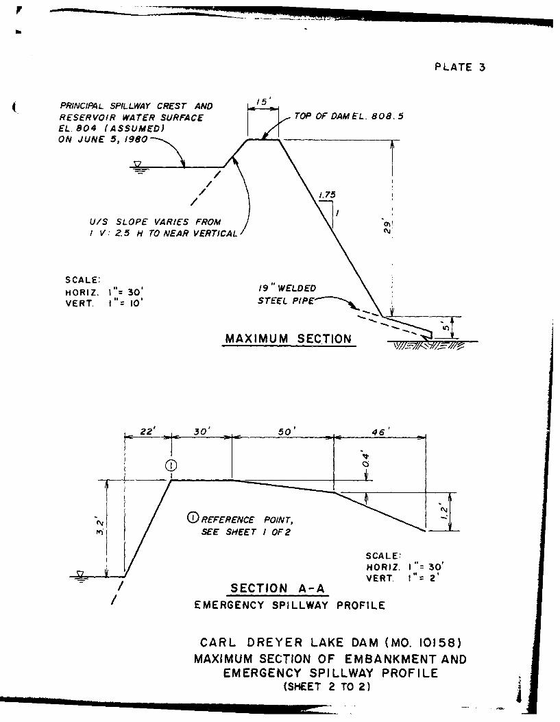
PLATE 3
( PRINCIPAL SPILLWAY CREST ANDRESERVOIR WATER SURFACE TOP OF DAM EL. 8 08. 5EL. 804 (ASSUMED)ON JUNE 5,18
U/S SLOPE VARIES FROMI V: Z.5 H TO NEAR VERTICAL
S CALE /9WEDE
HORIZ. I"= 30' 1"WLEVIERT. I"= 10' STEEL PP~-
MAXIMUM SECTION
22' 3 0' 50' 46'
[-- _ _ _
HORIZ. I"= 30'77T 1:2
-/SECTION A-A VR.I=2
/ EMERGENCY SPILLWAY PROFILE
CARL DREYER LAKE DAM (MO. 10158)MAXIMUM SECTION OF EMBANKMENT AND
EMERGENCY SPILLWAY PROFILE(SHEET 2 TO 2)

NN
j 307 -- 0
-0 7
-- o Al
law -

PLATE 4
te* 0. .
I' ep - -4.
II
4.---- I; .q I-
L- 2 -
U. S.DEATMN O GRCLTR
SOI CONERVTIO SEVC

WATERSHED DATA AILALE SUAIIENT a SLLWAY SCRAGE,1
o~a..,E Ste" Ale £ -L p.
ha'l S410.u* ~ ' o E AUSO F P004 ACf a., At Ft m *
Owes of 0se'd O- __0Cu O.aloM.*0,q. SO' G'..o .a. m . V AC-..
filled DOW.4 :.-I0s C.. A.L.. 0 .'CM . ,j~~ ~~~ ~~ 0..4 -~~9 C..-e ... M-0. M9C
La'440 of W-W~sA -kc F~eel ~ ~* ~ ~ ~ ~ .Ite~ 19 w N.ag-o0h 3400011 We9.. ___
ofg V401-tvI
* - I-ofU-fo0 Sh0,*.qru 0-.AD- .0.1 .,6T
P Tno .-0 fel 11.14 0 ~flydO00t - 4. -
~e .al of tm I40 -A0 &act*___ £09
(99.'.90d S(CET STORAGE 0410.144 AC Fl_____
7-
.7 7
......f9I L 44 I . ... ~ ... 2 ..... -77 7- * ~ 1 I~
*~ 1 7__ __
9too fee lime*3 09£ 4_______
HYDRGRAP DAA am "Yw sp'W4
PfllP$CWAL fmcflcwc~y m"I pooC
S~kLWAV MLWA
_________________________"___________ Cmg.A-~.'/~wFe.C L r i

WEIR ORIFICE CONNAUT WEIR~ -____
a be. -ft *l43* r. ----------
Id1_1 _1C"_____
A~~3 *fSAD
* .- S S - S
'Ws - vo,
V . " .a It*W .-
-a-L- - - -
-~ ~ ~ :5 .4 . .... a
,-a. - .. - -0a -A"t a . !'%
.- . .. .. ..
-7 _%z -.
* l j j a4 i .. - - -- atwo~.
.. Ia a toll-
77 . 7
am. ot
-
am I -4.." It w
I -at".

PLATE 6
b _ ,nua
tee
t-.v Is Mci'
0, 1 02304 ie
Be Lo A IN O ANOTE:~ ~ ~ ~ ~~m LEEO HSDA SO LT
REFERENdiGEOLOGI" -A ---- M SO R
DEPATMET OFNATRAL ESORCEMISO4 ccLGIA SUVYR GO ATGOO IA A
K~nnTH H ANDRSONP197P-n OF
CAR DRYR AE A
• " .; _" ',_
CARL DREYER !LAIE DAM
LEGEND
PERIOD SYMBOL D ESC R IPTI(CN
QUATERNARY Gal ALLUVIUM. SAND, SI LT, GRAVEL
r~m ARMATON GROUP: CYCLIC DEPOSITS
-- IENSYVANAN F SHALE , LIMESTONE AND SANDSTONE
Ic HEOE GROUP: CYCLIC DEPOSiTS~P~c OF SHALE, LIMESTONE AND SANDSTONE
Mo KEOKUK- BURLINGTON FORMATIONm
MISSSSI PIANCHERTY GRAYISH BROWN SANDY LIMESTONE{Mk CHOUTEAU GROUP: BACHELORAND HANNIBALFORMATION (LIMESTONE AND SHALE)
DEVONIAN D SULPHUR SPRING 3ROUP: BUSHBERG SANDSTONE,GLEN PARK LIMESTONE, GRASSY CREEK SHALE
SOu MAQUOKETA SHALE, KIMMSWICK LIMESTONE
Omk CAPE LIMESTONE
3R00 VIC IAN ~ Ojd JOACHIM DOLOMITE
Osp ST PETER SANDSTONE
Ojc ~ SMiTHVILLE FORMATION, POWE-LL OjcDOLOMITE
.71.
-
Ct
r4 4
L

APPENDIX A
PHOTOGRAPHS TAKEN DURING INSPECTION
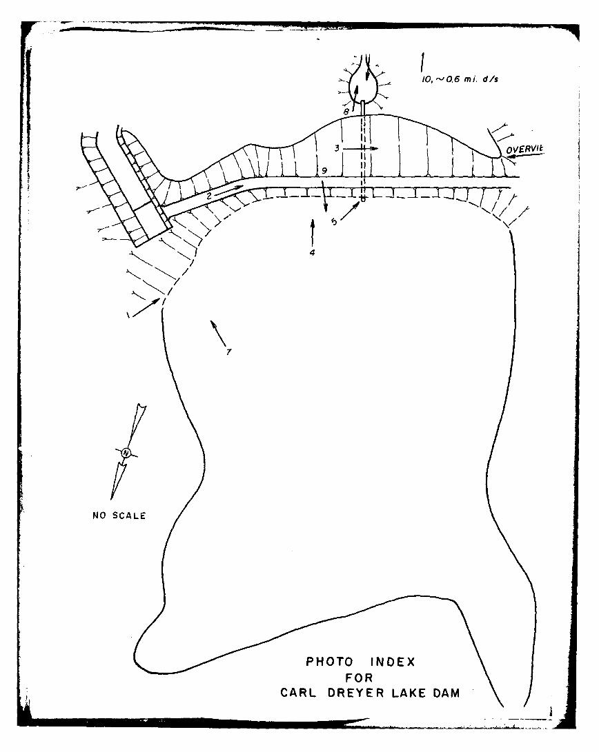
10,-0.6 mi. dis
7
NO SCALE
FORCARL DREYER LAKE DAM

Carl Dreyer Lake Dam
Photographs
Photo I - View of the upstream slope showing the location and type
of the principal spillway.
Photo 2 - View of the top of dam showing the maintained vegetative
cover and the curvature at the intersection of the two
straight lengths of the embankment.
Photo 3 - View of the downstream slope showing the dense vegetative
growth of grass, bushes, and trees.
Photo 4 - View of the upstream slope showing the scarps caused by
the wave erosion of the slope, some undercutting, and the
scarcity of riprap.
Photo 5 - View of the principal spillway pipe inlet showing the
steel hood provided as an anti-vortex device, and the lack
of any protection coating.
Photo 6 - View of the principal spillway outlet and the discharge
pool. Note dense vegetation on downstream slope.
Photo 7 - View of the emergency spillway control section showing
trees, and dense vegetation, and partial encroachment by
reeds which obstructs the inlet and discharge channel of
the spillway.
Photo 8 - View of obstructed downstream channel just downstream of
the principal spillway outlet.

Photo 9 - View of the reservoir and rim.
Photo 10 - View of a dwelling approximately 0.6 miles downstream of
the dam showing the downstream channel (Smith Branch of
Clear Fork Creek) on the right side of the Photo.

Cairl D~reyer Lakv Dain
Photo I
Mhot, 2

Carl Dreyer Lake Dain
Photo 3
Photo 4

Ca:rl D~reyer- Lako D~amr
Photo 5
Photo 6

Car D[rL-yur Lake D~am
Photo 7
Photo 8

Carto 9ryrLkeDi
Photo 10

APPENDIX B
HYDROLOGIC AND HYDRAULIC COMPUTATIONS

*a,
'C '
>NEW FLORENCE QUADR#tMQLE,
MONTGOMERY CITY QUADRANGLE.D/HARDZN
-A, CCATON
SCALE 1.-4 00
S 03
" "a
1' ~---DRAINAGE BOUNDARY i
CARL DREYER LAKE DAM (~.Iofs)DRAINAGE BASIN Ablo
SDOWNSTREAM HAZAWDZON4E

4PRC ENGINEERING CONSULTANTS, INC.
5AF-IFTY~r TAUSPCrufJ - IM155OURI -SHEET NO. - OF___
f)a~AIm ~ 5A~ F2C Z~ ,1yAp ZQ foN /'/ J01 NO.
RER\/cUPi EL-FvAntiON -AREA, QATA, By D..ATE~L
ELEV R~i li
(A~.L)5URrAcE . J9MA~R K5~
/V//
- c.'4 w~lz -~ - yewAQ /A,

PLATE 2, APPENDIX B
"- 0
cI1:
0(
__0_ 0 Cov0
w- QDc
(0 4>; •
4cr
-)4w
-. J >z
0 00 0
ZU) o -
CAR DRYRLKEDM(O.11J
w
W~ IL
-0
0.
0
133-4 (ISM) NOI.LA313
CARL DREYER LAKE DAM (MO. 10158)RESERVOIR ELEVATION -AREA CURVE
1-PRC ENGINEERING CONSULTANTS, INC.9p-x AFETY~ TwN5P-r-lipN MIt-ouRA SHIEET NO.OF--
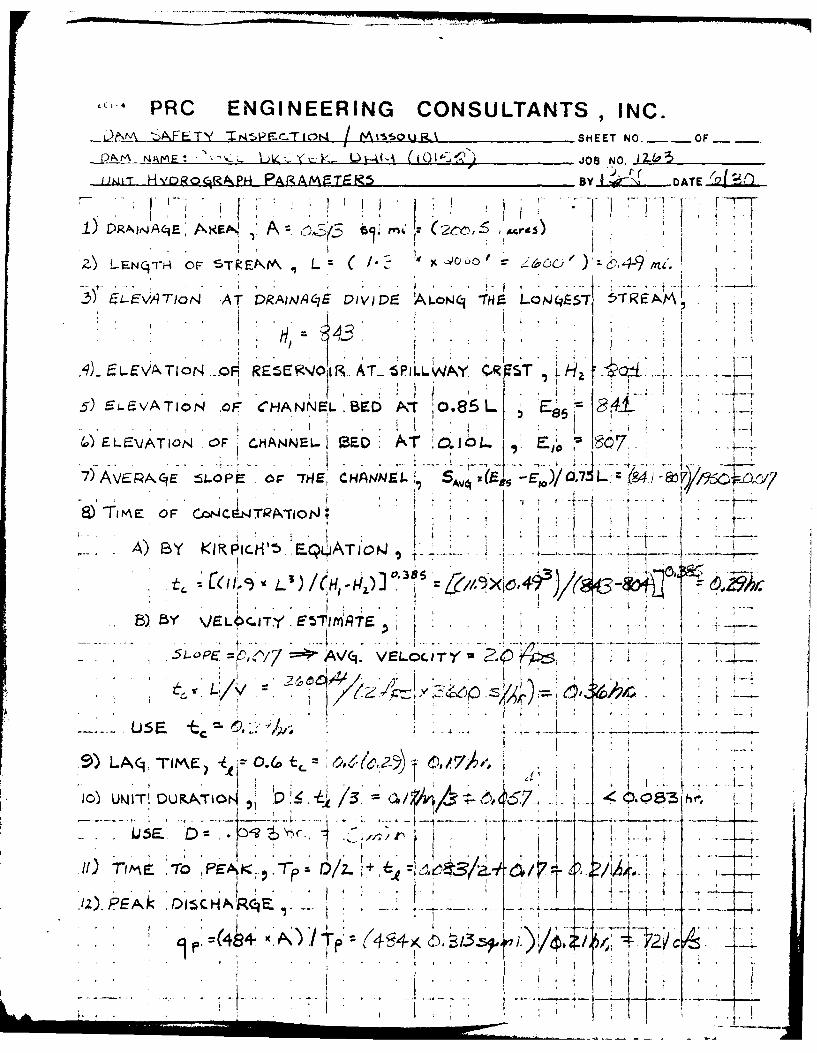
DNS _NME : . A~ ( k )i-~'- ii' JOB NO. 124p5
;'w'T HypoRALPA PARAMETES5 BY I AE
Z) L-FNCj-rH. OF $STRFNIA ,L~ z C* M/jj -,
T o A TDRAIbA6E DIVIDE A LoNIli~ P- Lo N(.5-f~
,'q)- E.EVi\TION-.o REE K'403R- A T- P ILL NAY. C ST I LHa.5) 6LevATION .OF CHANNEL .BD kiio.6S L E 1~
E~ ~LEV AT 10.4NcOF C.HANNEL1 3ED. AT O.IO6L.. :1
8) TIME OF Cjr*C4TRA-TloPJ~
By KIP O'-' EYT
s-5LPC =L,^/7 vA/(. VELOCLI-Y~ Ze~
U 5V E
10) UNiIT; DUKATiO~ 10:-4 3' -4 1 H
Q SJE D. A-<---
4-7:ix:-PE~ 01C . . -I 3/I,~Ot L.'77
I447 p: L77 <-T- 1i"i

ECPRC ENGINEERING CONSULTANTS, INC..DAN, -SAFETY' TNS4PF_:C-rI4 / tAlSSOLJR% - I9SO SHEET NO. OF_
DAMA N\AMAE: C AVL. 1>iLC-Y&A- L?44 1 Jo'Nz1_a"
ChIUAJE ~jMESFR OF-FLMIKIATION 8 Y 1{DATE (0
P 4ROW -51- P I HF TIRF _ NTF 4' '
.. A, MG. It-
5mEDPRcm7
WEI H I V -
-'---- 1--) 1

C14PRC ENGINEERING CONSULTANTS, INC.iZ~A ThFE-y~ 7tJ5PEaCrIOrN A MJ5nua i SHEET NO.-_OF ___
f~~~A.%A~22 --M~ -Uu i~ - - -io JOB NO. iIsi~tL-E AAXUAUaA Pi;rctciTr,c.1 By I ~~DATE.4L.
1 7 [ ~F
~~DF A~1
1) raaacuoFJ) ba~ fJ)D~ec~~e J'naye Cct Co-t -r
2-5 AP. T tc~exka-in J- r D.A 4
i' i b4C! r%
oi ni,
Ptrp-(fr[om- a F;51A#,r-
RaI. fc4 1
,.i .. l -for
Du reteoi on qrcevo of T-uo- 461' Ra
~T-1
Zore.. .I :L
...i

~ I- ~ I -CIL
I '. -~J,
I'
~J 20
K 'I ~ k''~LK
31R,

I -
Id-I %I F
, 7,7 ft -I
=7I
*00 80'n8.2 0 0 4 L ( w
sil 111.1 R. vio "-a Sil a.l .1 ), 301 1*
III
-o o
2 0* Itl 0 .
0 'I 7
2111

PRC ENGINEERING CONSULTANTS , INC.- 19/9n'4 ,-, SHEET NO. OF_: :-' -.-: 'F,7 E.> : ,/:/ 'v -~.q Joe No.,- ;
IL R DATE
',,'E ,> :Z't/0 :-.--- C:W-,zs' {
12A T/C/Vt/ W M5Z /}A' ,7-1. 4 4 , ,, -g l- -
, ,: 14h/..... .. t a_. . . ..
26..
.. . .. . .. .. . . . . ... --- '- . ... .. _-- . .. . .. -... .. .. ..
)"-Z 641 W ....
4i.,. .
Li
.-. ,--. -- D . '92,D i, ...
.,.-. I; . . s 7 . .. . .. .. _I t ' I

cPRC ENGINEERING CONSULTANTS, INC.* ~ '/"FY JA~PF~r,6A / M~ juJ /'Z'~SHEET NO.20 A
-Y~ ~ '2 O
S".--- -
t v.--
V. .
7 ~7
..........................-.--.. J
. . . . . . . . . . . . . . . . .. . . . . . . . . .
S-- -.. .-.--- -- . . . . . . -.- -. .- - - - -.r- -!
3,5 V .I -
S. ... . . . .t

.. ........
1.x "7 7V 1-.--~- ----------- 77---i- -
40 .- ... .... . .
*r a
t - . ... .-.
1 -A
..................................... ...

--- 7 -7' T-
'4 tti44
___Il .
F4
+4 I- r
4 -4
- -____ _ __ i - ~ L ~ ± -~~- 77
________ 11. .__ T___
t ..'t 7
-7'-- 7-
'Dis

PRC ENGINEERING CONSULTANTS, INC.S/ -}'TP~-r JA1t~~~let-'9 SHEET NO. OF 4DAFZ'£~~~IV! ~ Q 1 6 1 ? JOB NO. 1216 ____3
.. J. : , -. ' / ' 'A/.)*' AQA/P. vc'7"iA/ ,2 77AA CZ-JOr" BY-DATE ,
N. V
19
44A
- i t~:
I~ t
~X24

PRC ENGINEERING CONSULTANTS, INC.___ ~TL //AtF-7A- /'rJr 192 SHEET NO .2O3
~~ e) Y?~ cle~ L-J41V (l. ~~ JOB NO._ _ _ _ _ _
I 1<
Vi NN
9r' .
~C" All
N co
A, 0 j
- Y~------
-~ ~ ~f~ rj
c' Al (4 V1
ko~

]-4 PRC ENGINEERING CONSULTANTS INC.-- ° . .,re / . - /99O SHEET NO./ OF /
L; ?.. E A- (),911l1 /O0/ 8 ) JOB NO. i2 4, 3
SLQtd M/ F- .A // FM9RQ.9AlCY SPIw.. -Y BY JLK DATE 9.01 2..
I , I-4 - --- ----
. ). L _ _. . 4 .....-2.
l"+
{~t .- ,,e/, . T ... .
, cdvia <&.24 .0. 2,.1.
s o , o s : < -. z .. .. '._ L . ._ _
'e~ ~r~i.'~he~ spiwiaj a#d o-ke A>so the ofmh ?4 i jwAy: , d'. 1.. . . . . . . . . . . .

PRC FNGINEERING CONSULTANTS, INC.
%F-~'7 fL A-A7TMV6 e-IRNIE BY -)D ATE h&
1A, her
.0 604. CAC
&~,:779 gLe0I 29
31 40
47 / 7 47,
6 , 54-7IF2 417
4-
-4 ....
481 i. ..
33.9 4e....
;73 43 ,. z 2~~..-- 7 a . . . 7_ .
4?
• 73
in:1
a,.. 49 __ k w
, / ~ 4 4. ..- 4 ....I~ ' e / ~... .~~ &.. . . - -

j PLATE 3, APPENDIX 8
___ __,_ __ i - -'
.,, '_ _ C
-1 0 "o
'A -J __
0)
0
>- (L
wm w
cL) I.
a.,Cl)-- __
aU w
ii
ww
I- OD >- -g-
t~tl
.334 '(fIS ,) NOLVAT13
CARL DREYER LAKE DAM (MO. 10158)SPILLWAY AND OVERTOP RATING CURVE
..... F~ .777
o 3
7 77
7jj~--7j
_4 7_ 1 _7:L
_7 5r~77
44
____1 414-* *

HEC1DB PMF INPUT DATA

C-1l,
-4 u l4 r - fli V) )
u I
C) -4 Li)! 'riC
a-- L3 0 * s 134-
445, C) -4 v- tJu In~c
*~~~C 1 aL* 01 .C.
>- Li T.(
C' 'Ii
C'~ :~
- . I
Cl) -' ,n
a- -
4 1~*c, *-. .j 4 (1(1.*i' JJIL* N1 *
d/c U- -1 L
cii
0i '-1 .4 - - .q - C;(' j J
C', LL

INFLOW PMF HYDROGRAP1{

A.4,
'Cd
*.* .* .. *..** *0 *.** . .*..
'1 4 41 4 ~-
9. -
1 4. 1- I..'
* . ~
- .. 'I
-1
U
'a,C COC - -a
2
r I
- .~
.4 .9.C 0- 5 . 4 I *.- 9.4
3 ~.t4
4 -
I ~ I.,
*-2 :Ieiik. t4 I' -~1'I *~~' I *I I* I t 9.4. (
*

4..
.4
* . I I
.~ .~. C..
.y /E~ ~q4
? ~ 4
, 4 . .4 .~-i S.,
I ~1.'C. ~C
~h2~C.~ I
~ C ~
'C
*J
I
CW.\
,4. . '1 - 1~~Ji
.11 . 4 4
jo I b-a l.a...
* Oc
4.
a -I ~ a
* - 4.40
4 I
.ca
I CA 42a
* '.4
- ('JO I SJC~
(.0. a ~ -
A.-4 44
0. -~ .
'2
- C.1~ b-a 0440 CO
a. (.2 4-Sa.Jt) . *-CI 4
(.3 C. 0 ..- ~ .~* CC
CC - 4 - a '.7 -. 7-- '4
-~S Z
0 . bS.4S-S
0.4 - .~ -La 40 .4 0
* * .- zrb-0 .. U4 * C4.0 - 4.4
.~ c-S * ~d ~4 ~
400 4.47. C - - * -. .0 4) b* S.. 4.4
I' - C. CC .4CCC &
* 4. - .. .4 - 0.4 44*
4) 1 - * 4~ - (C(.0~ 4.4 (C('( ~N
b-C Ifl QO (Jr. 0. C4 CC 30 0(3
~ *400 .JZ 3 047* W.5
0 0
4 ~ ~ .44 44 44 1
Zr..- - 44 C4 0.- a. a
-U. I -, S
,-z '0 --
~LJ4 ~ .CC c.a '!a c
~4 - -.
.Jf 4j .-J .J - .10
44.440 0.4. * 40 a-si
.4 ha *. = ~4O - '~ -.
417.1. C -'.4. 4.3 -
-~ - - 2 -
24) 4. .J a
0 4 * S..* 4.3 I
244. ** .. . .4 (.~
2 ~. .~. S...
7 4. a 4* A. 4941
- h. .J 02 (*(
40 - 0.. 0' 4 - ~.
Zr '~* ~ ~%4~~C 0
-~0a ~*
- 4.40 '. 0-0 T
24S~ a * .-
.~ ~
... 0 - . -. Zr -
* 44 -~ Z
* - ~ 4 .. * .5
* , . ~ ~14 a.4, *
-. -'~
.4,,.- .
-ro' . *
V
a.
4
a -,
*4 +. 4

-C C.
r .. ;Z
1 ,. .. . tItCM
. .* . .t~ .0 .r
ln r . Q -,WI,'fU Z n 'D Wi .. ' I~ I.* - .- I. - 9-4 I. C ** f0 a0 Y . .-- 9.'- - - - - - -- - - - - - - -
- - -, -. - --
-' - - - - - - -I a I C0. . . tl 11 1: . ':. . t '.. I, Z
ti"~~ . . .. . .. W . . .4'.
. . . . . .... ..... .
In I U...W l' .tI 1 I I PI :M2Un .1M - - - - ~ 0d *0-d, In I $ 'dWrCIng'4V WI I
,- II, -
Cam.
0
445
-
.
2 'A
";2~~~~~~ .. .. . .... . ....... .. ..... .2 .............
;.A~~~ Iz -3 -4 -04
-.- . . .
I. ,
.. . . .. . .,
.. ... .. .......... .l ... ....•. .. . .O
noc0 tC fs C C ac ~~ c ,.,e lC.C C ~ COSo'ac I eo o c~C) CC' 0 0'5 C C = 000 0 00t~ )0 C C C C C C t C CC' ',C C 21 0 0 C - 00 00 C0:t
. ~~ ~C e . . . ... . . . . . . . . . . .. . . .
4F , N rt t rr n '- 0 J0 .C ~ t C - o c C c t C 0C C t C ~ C-c ~ c ) fo 0
earc. -ze4C o4a, I Cr. z ce,.e..t-.tc~aa
-. ~~~~ .0C .e o 0 0 C0 C C . . . .. C.
"~~~~~~~~~~~~~~~~~~~ AC? .. C.tC -a4 toO ,--q3'7-,.10,- tc. .C l t C 1~c ~~ 0C .. g~
V 'ao w at~rl. fC) Nv-o V C % J)C l1 *0 t,#W .~~e ri ~ aO , 1a 4 C Cia
h0~ ~ n)
MEN" C)S0C C.C~lJ4.C >OfCO C.t~C~fC .fl~C~gv. C ~ act

M~... see...... 0.e.
- - - - - - -~ do M
?-44. . .= g 401 .
4 1, 4 n
I N I 1I .. ,1 Nc
4 1
fa~aa c'aa os 4a eoo.u n.-a a
1 4' 1 -1 1'
IIf
71 C

PMF FLOOD ROUTING

O-AI0'4 610 PRC COIOSOER TOWNSEND INC ST LOUIS NO F/S 13/13
SEP so W S SNIPRIN DACW3-S-C-0094
UNCLASSIFIED NTOA ASATYPOANCALOERLAEA NL(O11 ,NECUliiEEEEi2EEIE2EEEEiEEEEEEEE
EEEEEE•hEL:

. . , . .-.-
""N
* 9 .: * e,
.. *. . . , •p
W. °1 .
.- 4. 4. ° .
10 Lnw
...... .i . .. ..+ ...,
A r C
,~C . . ... 9 +.
.. .: .. .+? ... .. ..,= . .. ..
+ 14 ''= ' " -'" .. 0, r:
o,
2.4 -.
.1 1 . . -, I.n•
,, ! *,- .-- 0 -- 4
. . . .. . .. . .. . . . , .
,, +-. . 0'. 4 ,+ .34 - .4 00.+.
42C4- 4 .. C 30..4 - J" 0.. . C. o ' .,,.+ ... ++ . .. . :.+. +., *0 '..
-*,'W:a -. : + '- 4-2 " 4. +'
4 - "* . ' "a. .40'* t+ C J :. - -; +. a - L:
: ,. ,-en.. . pc'4 .. 4-_ : .% .-<42 PC 4 X . " 0+0" t mO . + + .
,4' ,..Jc. ++ .,
* * *-1 c
4 . C _
~4. O..S - 400 **15.
4*4S*~t4

.. .w ....
14 C.1 4 I 11 N
21 JI'
.4a W- 21 1)'~t t SIcco~ t g t : w r d Inr~ a) M , W a 0 h~ t b a n o
-- -. -- --

*444i
444a L, . . 4
40tw 40 .0.4
a4 w4 4D m~4 *.wW,. m 0 Z-
ff. . . . . . . . .d . . . . . . . . . . 4 . - ft4
........... . . . .
-j Ak'4* --a m .N% -,m li'p )m 0
W-0,
. . .*. ..... . 44.
M4O40.D~W, ~ 0.lW~ ~0OW 44~4)' * 5N~5..4fl~4W:j4. 0 45l5C~S *'N#44
.a #r
44 l 4 *44
44(4 4. 4

9"M~
0 .
'7 . I .t , 4
+- Y
44 . • r. *- .
.. . . . ... .... .
- Ot .UW
... . . .. ...+ . . . . ..++, . , + .. + k.- .
. 00. - .. 4 *,+ -a,: s . 4 44
..1 .-. C ... . 4
4' t t t ' owo "+ ~ W a W r+ .'I + • WA 1 -a : P + 4+I
.0+ " ' Z : J a ,- " r "i N. w. :+, - " . -9 N C
. .. . .: ... . . . . . . . . .. . .
+ + '.. . .. . . .. +... +. . a# -. .. .. . . ....*. Q ~ O ~ t.. .... ..
W. 0 4% L, r 2 t - -
- -4,-' -" -
+ ' , ' rc . -.. . . .. N.. .. . .. . .
----- --------.---------- ----------
* ...*,i+ ... **e.
4 4
• + ',.,, t4,+,, "..
4,
>..i "+ + ' + V.
.+- . '
• . , . ~ t '
. ++ '."+ : , , . j , J
i i i ii iiii i IIi i~ II II i II II I I II I 1+o A

44 L 4
. . . t
*' ":I' I ' , A .."
. . . . . ...
0 -n
*- " 4.- , ". .-,
"z.aa, al' , w. *O ' W ah e : . 4 : - . .' o ...
. . . . . . . . . . . . . .
ao
4, o -,P. ap00C
. .#.*. ... .,.,.,... . . . . . . .. . . .. . . ....*-.S. r-.- .. N " . . ~ ~ 0 C S - ' 4" ' - - . ' otis . ",.or " a " ',-"aI ,.- "
4d. , W -
n m 1.-1--------------p-C----------I--------------m---------Dw * . .. u W m
-~~ --- -- ---- ----
., ...... .. . .... -.. . ,c, -r A r..
- --- - - - - - - - -- - - - - - - - - -- -- t " -- . -'1 - .- - -
... . . ... . ..... . ... .
..- 1:Aii
" * .. .. II il ... j t_ .... _
4.i . , . iir .
A61
millI

* i
" .4 4' . .
,.. .* C , . -. , .-
• .... . & -.. . . . . ..... . .-..
. If, n .
. . . :=
.. . .. .. - C. .. . . .. . . A's.
-r .. * N C-4 V. t.44 r4 M.C , f V4 Cf -. ", C% t t4,L "
il ..... . = :. .== :o ... ,....................... d+....... -+ ,i,'... ~,+
,, " :.. C% t4 4t 4-NC)C JIC; ', C I ( C N ~ ~ ~ l d N ff ~ t N . W ,-.+ ' . ,~t ,. CJ :,.*
- - - -- *1--,
C. a 4 Ioc 4 4 C 4n '..lCC .9 . ,: C l ra .- : .U :,,WC r,,. C4. 'C . bto0,,
SC).~~)C 4 . 44 dCCC.N4N. .C',44,.t.CV PJOC . ..... fl. dCSC Cfl4C'. ! I +C'
. . . . . . . . . . . . . .. . . . . . . . . . . . . . . .... 4:w . . ,~."44.". + . " . • -
CCC . o , , I ++ +. ! ,.'.eI'- *.'r .l+.
' 4F.. ,! ' C '
4-..

'II
. .9 .r
.. .,
* -
r a' ,,, fa 4 b: C ..-- I
. . .. .
Aze, ,
"p
'
' "
I'
.4 ,'4
-,
.
J"
-a "

SUM4MARY OF PMF FLOOD ROUTING

gt4W
K' A
* 00@00.. @600......
.4< -
I V' '~ A
.44 * ''A. ~ I ~'
1 ' r- '%~j *I I ~ *1~
'1 asY
I p Jr .1-
2,' , - iiiV 's.' J '4-" i-r
afl , tI'$4.,-*t.rr ~
4-'-J -
C . . - A "~ ~
. 4 I.
4
A , ~ ~ saL
4A Zza ~*' I A,
'4 1* Jr.
* .. O~
'~
.r a .L~"~C *~t~* A, ~6
* *>x . . . r~ '; {2 't;t~$~ ~r&'*,~.4
'.4* ~.. ~ 0
~ 4.
I. &tj"~-'~ , Cs I&$I~v~4 I *PAC&sN. ~
4 - ~ ~ 0

I.
Ii a
HECIDB ONE-HALF PMF INPUT DATA
3.1.

C) t') *W) K) ~fCL C) -4
CD - .C3 4 J)
o~' -UCJ) F (
OZ 4- CY JC*
0 Li 3f
C' am. mr- .
V) Of
U'-
'C. LI c .. q
(I .w .- 0) C
L'0L .7
0C. C' _.
41 LJL. C)~ ) JI~~s~
L)~.~ .~35).- * up- -4

INFLOW ONE-HALF PMF HYDROGRAPH

4A
<4-
-. -
4 t..1 I'~ $
4 *~*)~
1 ~ '4
'~ ~
zA'r*~' ;~~I
t C:.. J
I.< ;4.
V I
7
- , S
o ~ A. -
'I..

it..i
I.. .I'
0 A. .0
1', I a e, 1: :
e 21 =*'
ry.4 4
lw :0 .2 % j
co .-. ott.e
S~~~~~ I I -2'2
N t, a~ ~..4 S4 AA1S4!
ta4-. .~-,NNr- * Z
'A5.0
4.6,a-a .

44
-cw v &-..- * .aW. *o - =:R l.J'A 4 10' ! es -I. i in D w I-
A .4 . . .. . . . . . . . .. . ... . . . . . . . ,
rW 4; :ga ~~ = . 0-, = ..-aU., ' < ) C: 0 Ot. , 0,3 . .. 00.. t%.. ............... 0 ............
.. . i,.,, < fl r * ... . : " , : " a " • " . .
..- 4, ( - .. J0.........J °U 4 "J'NCf, A .. .. .. .. .. ...... fll 4 1 .!.4 ..........
-. 4%,, ftf
= ~p . 1. . . . . ... . . . ... .C . ... .. . .
- ' "i "j
--a A_..*d1 . . ... . , , ,. ,4P .z .o ,- .4 q4 ...... ,. ,1 .4 14 N T vw
-.*..... C. .* 1.3eS S 0O .N . . .Cf OO... .... *1 .. . 1 V fl3"f"~d
" ,'. ... .. . ... ... ~..r.Nr 3.*C. -v~rn~~ -e - -,, - - - - -r - -t, --
Q- u
•. :. "3 ,c ,Ca . C c a,.~t 4~ .. a - . C. , .. ., aC. - .3-c "'c.J ', . 3.00 00 . cc
.. .. . . .. . .
- -- - -
.. "" co -o C a - ~-c.. ~A C c....f.. r4' " ....... . f V .. ....
8%, 1" 1' i -. -I - " .
In44- -w j.* - ,. . Q.c OC.C .e C . tr a o l. ...... - '..' ;.-. ~ i '
= .... ......... o .... 444o * =4... o- .. .%7 . .d... *
.-.-- "4 "0-S . .4,. ..cC. .. " efl0'-.P! ' .. 3C)i4* 4 oC.t
• • • .-4- j*~**- -- - - - -' -n - - J -- 4 .4 .
4.4F
-C.- ***** * S0 0ee @0 SO

'Att..- , 0I a, 11 'r W-MW--av . n.. * . 0 ..................
.. ....... .. .... ..- . . . .. ..
in . , •
4 ^ C. " N
*~~~~ -- -. ' -r -~ -s -t - -. ---
.... .N,. c~fCc N- ' o - N e c.s 47 a, .1.1fWCC. -D
Ie M
. . .*..I.
-4 C - 1
. . .t . . . . . . . .. .. .' ... , . .. .
S . , .'
. . .. . . - .. . .
let
c5 6 -aC.SU.+CU < e cC
t+0 .IC , . .. ... 2 * .,. ... .. - -'-,-

O4OOO:CC OE £In0i.,*, n 1c
4.~ . . .-~ .. ... .4.
4171
.. . ..
h- C4,
. . , c o t 0 ~ .. c l o , c r. z .4 C 4 .O . I
,,, o .aea c 00 C aC c ,04,C4 '0v
- -.-.-.-.... . .. ... .-... ,eo 4
-I1
r-4NC:.. N. N. C. C. .a ., .C C. 44 5.
.. -, , .. ... . 4 .. ' .,. ,)
lil l lLi .... . . ......4.b... ........ . .. . . ..... .... 4 44-, ,. .4 . . 4... " ec

ONE-HALF PMF FLOOD ROUTING

. .. . . . . . .
.- . 0.3... . . ... .4, '. 3O 4 ..
N fuCz-N -- CN\.C.~
M AD. 4 4
Lo 44F
-,..
Jr. -4 .
"" ~ - ... r. C.. . .C'Z:: " : : '..
'.. .'V t, 4. ": i ' : .. ,"..:' i. ,
. '...,,, N.,.,.S .... .3-. 3,.. ;,O,-
- .

- - - - - --
0 ,
. . . . .
.O OO. -. ;L 9 .) 'a .'c 99 . , ,' "9 t .O',
- - - ....
IM.
*~~ ~ 0C N)SC

.. . . . . . . . . . . . . . . .
'A Vm.,..
. . .. . . .... .
'A l -,-
- -----•-. .
-•
1)1
.. ...4J 4. "--4,o--t
.... *4 , -+ *C.. . ,, i . '.. . -;. .- ,- ..t . . " r. or- .hr r- - a . ;.w. aj "+-. ... ,- - - - - - -
- -
',p +.
I ..
+ ,
'"+ '+ e +:+
I,
. , . .,
,'. -+.+.'-

- ---------- ------
-~~ ~~ -ip -- -. --. ' -. r -- - - -
,C~ip'S. . .C- ' .... .l~ .. , .S .. .-. ....
* . i... 1- - -C.:, - ---- -----
i

f44;
.~ . ..
- - - - - - --

_ _ _ _ __,.. .. . . . . . . .. .. . . .. .. .- I.!:: : :
44i.4 i4
. I., ". .. . 7
-4 - -- --- a. m- - - 4 C C t4 ~ C t -24 - -W r' -.. a -~r -r~ - tx ----- - - W-- -- --.. .. . .. . .. ..... . . , ... ... .. . . .. . . . ...
4.. J. , Z ' 4.
':: i: ,i... .... ... ... ... .... ... ... ... .... ....... ..... ...
.- - - - - - -
.l IN
j C,
CA. .-,,- . .. . . . . .4. I I .. .... .- . . . . . . . ... . . .. . . ...... . .. . .
*444 gC..4.44 0 4 04 04;.. *..4 J.~.C..4C 4.40.C..C.... "
:- . .- - 1
II
-, , P. 4 t,
"- .
4vr - II I I 4I.433- -

Z2 ~
StThA~4ARY OF ONE-HALF ?HF FLOOD EDUTING
K

I C.
4--'
* 0S0 000a 0 0 S 0 *0 a
CWOR

+, -, --
'A
I
4 '-*.4 *~*.VWw. *
47.

PERCENT OF PMF FLOOD ROUTINGEQUAL TO SPILLWAY CAPACITY

-a
1--I'7,
A.j.'.*~ 1
7 1
'Sr A 4
*~ 47
4 *i I ' I
I- '2' $ 1~'-..
-, I '~'.1%K I -? . v'"-.9..
it~
-~ - I
V'%~~* I
,
r a 4$
p'I.TA * I
I910 S.Z '9
a VC raf' A4.34 Sc.
u.~ r,.~ .t ~
4 Y~ Th4 p4 t~,tA 9
""17"'
4'1. j
S 2 4
.. :.s~ '- NYC* , I I- ,, ){# -U.i2~'.~4'~1r ~* V~' ~
'2 ~ I. I . k~tZA4*'~44 ~
~ '
.9. '7 .9 .9 v-I 1 " i.v q S 'a~4% .44

I* A .m j
141
4, . - '
N ,h
4't~~-- fl : -~ ~ U: tr h 22lC. 4
L' K
- .'*lsx
-t AD'

tTA 4s*
rg .
VAV
'-a 0- a a

17 1-
'81
* A4
.7,4

u V'v
pAp
at a a . 2.-
-. ~ ~ ~ ~ ! . *. '/ 4 ~k i d-
4k
Nz1Im.4 . ~~t
1c3-~ a; 4 - / ~* 4 ii.'i 4
C I - t 1
.. 2p. A-
-4-~ W*U 00 44,A a 0 aC -a ..
REC-2 INPUT AND SUMMARY TABLE

4
r *0*4 .. ** * * * ** .. * ... 1
,'
4
I ~ '-0
jr ~ a-~ 0
5* Ct 3 ~ '3 00
4CO C C' t.
-,,-~ 40 at* .
..
t ~ *0
CC2C CCS C
CC Ci CC'
'A -, ~ 3- - .'.CC, ~CC C~ .iO
C * Ci C
C- I
C i., C-C. C' C~ '3 CC'C'
C' ~~0 ~' a--
C C, - a
C CCC -' '~W Ci
a- * * A
Li : : ~:.4 tC,
IC-C~C
C-.
C' .
C-i~' --
4
S -.
C -'C C~
-CC
* . C'0*~ )
S.-
~
A
- ~ -

. .... .. . K-";" ,-
"S" * .''". S .... " ...... .0@
A i
5'P
.4.... . ..... ....... . ... . ....
. .4
.. ~ . . . . . . .K . .-r . .~5 . . . -iC C
-1 1. . . . . .. . .. . . . ... , . . . .
hd

CC I0 C. f o oo
J6 Co~- C-
M - --ce-~ - - - - -
ii ~ ~ ~ ~ ~~1 tl %- 11 Cl 0. C.f 000

ONE=:
![TITLE 26 DEPARTMENT OF THE ENVIRONMENT SUBTITLE … · 2018-03-14 · SUBTITLE 11 -AIR QUALITY CHAPTER 02 ... COMAR 26.1 1.03. (10) [not in S IP ] ... (47) "Responsible official"](https://img.pdfslide.us/doc/110x75/5b381e757f8b9a5a518d14a0/title-26-department-of-the-environment-subtitle-2018-03-14-subtitle-11-air.jpg)