Embed Size (px)
Citation preview
Technical GuidanceReference Manual
IAEA Nuclear Security Series No. 5
Identification of Radioactive Sources and Devices
IDENTIFICATION OF RADIOACTIVE SOURCES AND
DEVICES
REFERENCE MANUAL

The following States are Members of the International Atomic Energy Agency:
AFGHANISTANALBANIAALGERIAANGOLAARGENTINAARMENIAAUSTRALIAAUSTRIAAZERBAIJANBANGLADESHBELARUSBELGIUMBELIZEBENINBOLIVIABOSNIA AND HERZEGOVINABOTSWANABRAZILBULGARIABURKINA FASOCAMEROONCANADACENTRAL AFRICAN REPUBLICCHADCHILECHINACOLOMBIACOSTA RICACÔTE D’IVOIRECROATIACUBACYPRUSCZECH REPUBLICDEMOCRATIC REPUBLIC OF THE CONGODENMARKDOMINICAN REPUBLICECUADOREGYPTEL SALVADORERITREAESTONIAETHIOPIAFINLANDFRANCEGABONGEORGIAGERMANYGHANA
GREECEGUATEMALAHAITIHOLY SEEHONDURASHUNGARYICELANDINDIAINDONESIAIRAN, ISLAMIC REPUBLIC OF IRAQIRELANDISRAELITALYJAMAICAJAPANJORDANKAZAKHSTANKENYAKOREA, REPUBLIC OFKUWAITKYRGYZSTANLATVIALEBANONLIBERIALIBYAN ARAB JAMAHIRIYALIECHTENSTEINLITHUANIALUXEMBOURGMADAGASCARMALAWIMALAYSIAMALIMALTAMARSHALL ISLANDSMAURITANIAMAURITIUSMEXICOMONACOMONGOLIAMONTENEGROMOROCCOMOZAMBIQUEMYANMARNAMIBIANETHERLANDSNEW ZEALANDNICARAGUANIGERNIGERIA
NORWAYPAKISTANPALAUPANAMAPARAGUAYPERUPHILIPPINESPOLANDPORTUGALQATARREPUBLIC OF MOLDOVAROMANIARUSSIAN FEDERATIONSAUDI ARABIASENEGALSERBIASEYCHELLESSIERRA LEONESINGAPORESLOVAKIASLOVENIASOUTH AFRICASPAINSRI LANKASUDANSWEDENSWITZERLANDSYRIAN ARAB REPUBLICTAJIKISTANTHAILANDTHE FORMER YUGOSLAV REPUBLIC OF MACEDONIATUNISIATURKEYUGANDAUKRAINEUNITED ARAB EMIRATESUNITED KINGDOM OF GREAT BRITAIN AND NORTHERN IRELANDUNITED REPUBLIC OF TANZANIAUNITED STATES OF AMERICAURUGUAYUZBEKISTANVENEZUELAVIETNAMYEMENZAMBIAZIMBABWE
The Agency’s Statute was approved on 23 October 1956 by the Conference on the Statute othe IAEA held at United Nations Headquarters, New York; it entered into force on 29 July 1957The Headquarters of the Agency are situated in Vienna. Its principal objective is “to accelerate andenlarge the contribution of atomic energy to peace, health and prosperity throughout the world’’.
f .
IAEA NUCLEAR SECURITY SERIES No. 5
TECHNICAL GUIDANCE
IDENTIFICATION OF RADIOACTIVE SOURCES AND
DEVICES
REFERENCE MANUAL
INTERNATIONAL ATOMIC ENERGY AGENCYVIENNA, 2007

IAEA Library Cataloguing in Publication Data
Identification of radioactive sources and devices : technical guidance, reference manual. – Vienna : International Atomic Energy Agency, 2006.
p. ; 24 cm. – (IAEA nuclear security series, ISSN 1816–9317 ; no. 5)
STI/PUB/1278ISBN 92–0–111406–0Includes bibliographical references.
1. Radioactive substances. 2. Radioactive substances — Transpor-tation. I. International Atomic Energy Agency. II. Series.
IAEAL 06–00469
COPYRIGHT NOTICE
All IAEA scientific and technical publications are protected by the terms of the Universal Copyright Convention as adopted in 1952 (Berne) and as revised in 1972 (Paris). The copyright has since been extended by the World Intellectual Property Organization (Geneva) to include electronic and virtual intellectual property. Permission to use whole or parts of texts contained in IAEA publications in printed or electronic form must be obtained and is usually subject to royalty agreements. Proposals for non-commercial reproductions and translations are welcomed and considered on a case-by-case basis. Enquiries should be addressed to the IAEA Publishing Section at:
Sales and Promotion, Publishing SectionInternational Atomic Energy AgencyWagramer Strasse 5P.O. Box 1001400 Vienna, Austriafax: +43 1 2600 29302tel.: +43 1 2600 22417email: [email protected] http://www.iaea.org/books
© IAEA, 2007
Printed by the IAEA in AustriaSeptember 2007STI/PUB/1278
FOREWORD
In response to a resolution by the IAEA General Conference in September 2002, the IAEA has adopted an integrated approach to protection against nuclear terrorism. This approach coordinates IAEA activities concerned with the physical protection of nuclear material and nuclear installations, nuclear material accountancy, detection and response to trafficking in nuclear and other radioactive material, the security of radioactive sources, the security in the transport of nuclear and other radioactive material, emergency response and emergency preparedness measures in Member States and at the IAEA, and the promotion of adherence by States to relevant international instruments. The IAEA also helps to identify threats and vulnerabilities related to the security of nuclear and other radioactive material. However, it is the responsibility of States to provide for the physical protection of nuclear and other radioactive material and the associated facilities, to ensure the security of such material in transport, and to combat illicit trafficking and the inadvertent movement of radioactive material.
Early in the nuclear age, radiation for research and application came from naturally radioactive material. Radium and radium-beryllium mixtures, encapsulated for safe and easy handling, provided sources for gamma rays and neutrons. Such sources had numerous widespread applications and their use grew rapidly. Control procedures gradually improved, but physical protection remained weak, and inventory information was irregular and incomplete. The subsequent development of nuclear reactors led to stronger sources, a greater diversity of sources and applications, and an overall increase in use.
Expanded use was, unfortunately, accompanied by a number of accidents, injuries and fatalities. This trend, and a particularly severe accident in 1987, prompted the IAEA to begin a programme to provide information and, in the case of radium sources, direct assistance in controlling and conditioning sources.
Since 1999, the IAEA has been implementing the Action Plan on the Safety of Radioactive Sources and Security of Radioactive Material. This has led to the adoption of a Code of Conduct on the Safety and Security of Radioactive Sources to reduce the threat of legitimately used radioactive sources being diverted or misappropriated for malicious use and to enhance the safe use and control of sources in legitimate use. The IAEA is involved in assisting its Member States with implementing the Code of Conduct, together with other initiatives, such as the development of an Illicit Trafficking Database (ITDB), assistance in the life cycle management of radioactive sources, promotion of safe work practices, and enhanced security during use, transport and storage.

In order to ensure that more progress is made, the IAEA formed a mechanism to provide direct assistance to Member States to help recover, condition and further manage sources. Properly trained and equipped expert teams managed the recovery and conditioning of several thousand sources.
A key area of concern highlighted in the Action Plan is the issue of orphan sources. Those sources were never subject to regulatory control when they were initially supplied, have been abandoned, stolen or misplaced. Unfortunately, many large medical and sterilization sources are believed to be in this situation.
The IAEA also has an important role in the area of preparedness for and response to radiation emergencies. The Convention on Early Notification of a Nuclear Accident and the Convention on Assistance in the Case of a Nuclear Accident or Radiological Emergency (Emergency Conventions) place specific legal obligations on the IAEA with regard to emergency preparedness and response. Under the Emergency Conventions, the Incident and Emergency Centre (IEC) of the IAEA coordinates the actions of global experts and the efforts within the IAEA. It also helps to coordinate the responses of Member States as well as other international organizations, such as the WHO, FAO or WMO in case of a nuclear or radiological incident and emergency.
At the request of countries, the IAEA sends expert teams to help implement actions to fulfil national strategies or to advise on and assist in dealing with disused sources. The teams work with national waste operations and regulatory bodies to recover sources, condition them and render them safe and secure according to international norms and standards. Within its 2002 Action Plan to Combat Nuclear Terrorism, the IAEA established a programme to ensure that uncontrolled radioactive sources are brought under regulatory control and properly managed by providing assistance to Member States in their efforts to identify, locate, recover, condition and store them in a safe and secure manner or dispose of them if possible. From these efforts, which began in the mid-1990s, and from discussions with national authorities and international organizations, it was clear that an instrument to help identify orphaned and unknown sources and devices is needed.
Following the recommendations of the IAEA Conference on the Safety of Radioactive Sources and Security of Radioactive Materials, held in Dijon in 1998, the IAEA Board of Governors and General Conference approved in 1999 the Action Plan on the Safety of Radiation Sources and the Security of Radioactive Materials requesting, among other things, that the IAEA “develop a repository of information on the characteristics of sources and of devices containing sources, including transport container, and to disseminate the information, with consideration of the advisability of dissemination through the Internet”.
The IAEA developed the International Catalogue of Sealed Radioactive Sources and Devices (referred to as the Source Catalogue), which details source characteristics and technical data for a very large number of sources and devices. The size of the full Source Catalogue makes it impracticable to disseminate on a large scale. The information in the Source Catalogue is in the form of a database and accessible only through a password-protected web site.
For this reason, this publication was conceived to provide a more manageable summary of typical radioactive sealed sources and devices containing sealed sources. Its purpose is to help non-specialists identify radioactive sources, devices and packages. It is intended to provide information to non-specialists working in border control, scrap metal industries, hospitals, airports, harbours, police and fire departments, and other situations where they may come in contact with sources accidentally or in the course of their normal work. It also provides fundamental information on precautionary action to be taken in the event of a suspected uncontrolled source or device being found. Early identification of sources in such situations serves both safety and security objectives.
This publication is intended to be a basic guide and not a comprehensive tool kit to identify and provide detailed emergency handling instructions for radioactive sources, devices and transport containers. In addition, this publication helps to identify sources and highlight the risks they present, and provides information on appropriate action. It is a small but significant step in the international community’s continuing efforts to strengthen control of radioactive sources and nuclear material, increase safety and security, and thereby make the benefits of radioactive sources ever more broadly accessible.
This publication was partly funded through the Nuclear Security Fund established under the Nuclear Security Plan. The IAEA acknowledges with gratitude the efforts of J. Parfitt in the preparation of this publication. The IAEA officers responsible for it were M. Al-Mughrabi and J. Neubauer of the Division of Nuclear Fuel Cycle and Waste Technology.

EDITORIAL NOTE
This report does not address questions of responsibility, legal or otherwise, for acts or omissions on the part of any person.
Although great care has been taken to maintain the accuracy of information contained in this publication, neither the IAEA nor its Member States assume any responsibility for consequences which may arise from its use.
The use of particular designations of countries or territories does not imply any judgement by the publisher, the IAEA, as to the legal status of such countries or territories, of their authorities and institutions or of the delimitation of their boundaries.
The mention of names of specific companies or products (whether or not indicated as registered) does not imply any intention to infringe proprietary rights, nor should it be construed as an endorsement or recommendation on the part of the IAEA.
CONTENTS
KEY INFORMATION ON RADIOACTIVE SOURCES AND DEVICES . . . . . . . . . . . . . . . . . . . . . . . . . . . . . . . . . . . . . . . . . . . . . . . . 1
1. INTRODUCTION . . . . . . . . . . . . . . . . . . . . . . . . . . . . . . . . . . . . . . . . . 5
1.1. Background . . . . . . . . . . . . . . . . . . . . . . . . . . . . . . . . . . . . . . . . . . . 51.2. Scope and objectives . . . . . . . . . . . . . . . . . . . . . . . . . . . . . . . . . . . 51.3. Structure . . . . . . . . . . . . . . . . . . . . . . . . . . . . . . . . . . . . . . . . . . . . . 61.4. Potential dangers associated with radioactive sources. . . . . . . . 7
2. IDENTIFYING A RADIOACTIVE SOURCE, DEVICE OR TRANSPORT PACKAGE WITH AUTHORIZED USE . . . . . . . . 9
2.1. Devices. . . . . . . . . . . . . . . . . . . . . . . . . . . . . . . . . . . . . . . . . . . . . . . 92.2. Sources . . . . . . . . . . . . . . . . . . . . . . . . . . . . . . . . . . . . . . . . . . . . . . . 112.3. Transport packages. . . . . . . . . . . . . . . . . . . . . . . . . . . . . . . . . . . . . 122.4. Identifying the transport and use of radioactive sources. . . . . . 13
3. ACTIONS TO BE TAKEN IF AN UNCONTROLLED SEALED SOURCE, DEVICE OR TRANSPORT PACKAGE IS FOUND . . . . . . . . . . . . . . . . . . . . . . . . 14
4. USES OF RADIOACTIVE SEALED SOURCES AND DEVICES . . . . . . . . . . . . . . . . . . . . . . . . . . . . . . . . . . . . . . . . . . . . . . . . . 15
4.1. Medical uses . . . . . . . . . . . . . . . . . . . . . . . . . . . . . . . . . . . . . . . . . . 164.2. Non-medical irradiation of products . . . . . . . . . . . . . . . . . . . . . . 164.3. Gauging systems . . . . . . . . . . . . . . . . . . . . . . . . . . . . . . . . . . . . . . . 174.4. Non-destructive testing using radioactive sources . . . . . . . . . . . 184.5. Materials analysis . . . . . . . . . . . . . . . . . . . . . . . . . . . . . . . . . . . . . . 194.6. Miscellaneous uses . . . . . . . . . . . . . . . . . . . . . . . . . . . . . . . . . . . . . 204.7. Examples of sealed radioactive devices and sources . . . . . . . . . 214.8. IAEA categories of radioactive sources . . . . . . . . . . . . . . . . . . . 22
5. EXAMPLES OF RADIOACTIVE DEVICES . . . . . . . . . . . . . . . . . 26
5.1. Industrial sterilization plant . . . . . . . . . . . . . . . . . . . . . . . . . . . . . 265.2. Teletherapy machine . . . . . . . . . . . . . . . . . . . . . . . . . . . . . . . . . . . 275.3. Blood irradiator . . . . . . . . . . . . . . . . . . . . . . . . . . . . . . . . . . . . . . . 315.4. Multibeam teletherapy machine (gamma knife) . . . . . . . . . . . . 345.5. Small scale sample irradiator . . . . . . . . . . . . . . . . . . . . . . . . . . . . 355.6. Seed irradiator . . . . . . . . . . . . . . . . . . . . . . . . . . . . . . . . . . . . . . . . 385.7. Radioisotope thermoelectric generators (RTGs). . . . . . . . . . . . 415.8. Gamma oil well logging bull plug . . . . . . . . . . . . . . . . . . . . . . . . . 455.9. Neutron oil well logging . . . . . . . . . . . . . . . . . . . . . . . . . . . . . . . . 475.10. Gamma radiography projector . . . . . . . . . . . . . . . . . . . . . . . . . . . 525.11. Gamma radiography pipeline crawler . . . . . . . . . . . . . . . . . . . . . 605.12. High activity gauges . . . . . . . . . . . . . . . . . . . . . . . . . . . . . . . . . . . . 625.13. Low energy gamma density, thickness and level gauge . . . . . . . 695.14. Beta density and thickness gauge . . . . . . . . . . . . . . . . . . . . . . . . . 715.15. Bulk material moisture gauge . . . . . . . . . . . . . . . . . . . . . . . . . . . . 735.16. Soil moisture/density gauge. . . . . . . . . . . . . . . . . . . . . . . . . . . . . . 765.17. X ray fluorescence analyser. . . . . . . . . . . . . . . . . . . . . . . . . . . . . . 785.18. Remote afterloading brachytherapy machine. . . . . . . . . . . . . . . 815.19. Static eliminator . . . . . . . . . . . . . . . . . . . . . . . . . . . . . . . . . . . . . . . 845.20. Radioactive lightning conductor rod . . . . . . . . . . . . . . . . . . . . . . 875.21. Self-luminous signs . . . . . . . . . . . . . . . . . . . . . . . . . . . . . . . . . . . . . 885.22. Smoke detector . . . . . . . . . . . . . . . . . . . . . . . . . . . . . . . . . . . . . . . . 90
6. EXAMPLES OF RADIOACTIVE SOURCES. . . . . . . . . . . . . . . . . 92
6.1. 60Co teletherapy source . . . . . . . . . . . . . . . . . . . . . . . . . . . . . . . . . 926.2. 60Co gamma sterilization source . . . . . . . . . . . . . . . . . . . . . . . . . . 946.3. 90Sr radioisotope thermoelectric generator source. . . . . . . . . . . 956.4. Industrial gamma radiography sources . . . . . . . . . . . . . . . . . . . . 966.5. HDR remote afterloading brachytherapy sources . . . . . . . . . . . 976.6. High energy gamma industrial gauging sources . . . . . . . . . . . . . 986.7. Neutron industrial gauging sources . . . . . . . . . . . . . . . . . . . . . . . 1006.8. Gamma and neutron oil well logging sources . . . . . . . . . . . . . . . 1026.9. Low energy fixed industrial gauging sources . . . . . . . . . . . . . . . 1046.10. Permanent implant and low dose rate brachytherapy
seed sources. . . . . . . . . . . . . . . . . . . . . . . . . . . . . . . . . . . . . . . . . . . 1066.11. Eye plaques . . . . . . . . . . . . . . . . . . . . . . . . . . . . . . . . . . . . . . . . . . . 1086.12. Low energy gamma analytical sources. . . . . . . . . . . . . . . . . . . . . 1096.13. Calibration and reference sources . . . . . . . . . . . . . . . . . . . . . . . . 111
7. EXAMPLES OF RADIOACTIVE TRANSPORT PACKAGES. . 114
7.1. High activity gamma transport packages. . . . . . . . . . . . . . . . . . . 1147.2. Radiography source changer. . . . . . . . . . . . . . . . . . . . . . . . . . . . . 1177.3. Low activity high energy gamma transport packages . . . . . . . . 1197.4. Single use source packaging . . . . . . . . . . . . . . . . . . . . . . . . . . . . . 122
APPENDIX I: RADIATION BASICS. . . . . . . . . . . . . . . . . . . . . . . . . . . 125APPENDIX II: LIST OF DEVICES AND SUMMARY
REFERENCE DATA IN SECTION 5 . . . . . . . . . . . . . 128APPENDIX III: LIST OF SOURCES AND
APPLICATION CROSS-REFERENCES IN SECTION 6. . . . . . . . . . . . . . . . . . . . . . . . . . . . . . . . . . 131
REFERENCES . . . . . . . . . . . . . . . . . . . . . . . . . . . . . . . . . . . . . . . . . . . . . . . 133DEFINITIONS . . . . . . . . . . . . . . . . . . . . . . . . . . . . . . . . . . . . . . . . . . . . . . . 134CONTRIBUTORS TO DRAFTING AND REVIEW . . . . . . . . . . . . . . . . 138

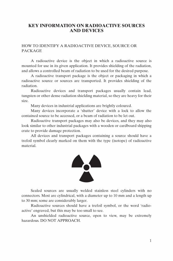
KEY INFORMATION ON RADIOACTIVE SOURCESAND DEVICES
HOW TO IDENTIFY A RADIOACTIVE DEVICE, SOURCE OR PACKAGE
A radioactive device is the object in which a radioactive source is mounted for use in its given application. It provides shielding of the radiation, and allows a controlled beam of radiation to be used for the desired purpose.
A radioactive transport package is the object or packaging in which a radioactive source or sources are transported. It provides shielding of the radiation.
Radioactive devices and transport packages usually contain lead, tungsten or other dense radiation shielding material, so they are heavy for their size.
Many devices in industrial applications are brightly coloured.Many devices incorporate a ‘shutter’ device with a lock to allow the
contained source to be accessed, or a beam of radiation to be let out.Radioactive transport packages may also be devices, and they may also
look similar to other industrial packages with a wooden or cardboard shipping crate to provide damage protection.
All devices and transport packages containing a source should have a trefoil symbol clearly marked on them with the type (isotope) of radioactive material.
Sealed sources are usually welded stainless steel cylinders with no connectors. Most are cylindrical, with a diameter up to 10 mm and a length up to 30 mm; some are considerably larger.
Radioactive sources should have a trefoil symbol, or the word ‘radio-active’ engraved, but this may be too small to see.
An unshielded radioactive source, open to view, may be extremely hazardous. DO NOT APPROACH.
1
A source is referred to as ‘dangerous’ if, under conditions that are not controlled, it could give rise to exposure sufficient to cause severe deterministic health effects.1 Picking up a dangerous source is particularly hazardous. Analyses of past emergencies show that severe deterministic health effects have resulted from holding or carrying (e.g. in a pocket) a dangerous source for just a few minutes. Therefore, efforts must be made to prevent the handling of possibly radioactive material. However, limited periods of time (a few minutes) spent near a very dangerous source,2 for example, for life saving purposes, should not result in severe deterministic health effects [1, 2].
INDICATIONS OF A DANGEROUS SOURCE
Indications of a dangerous source [1] include the following:
— A heavy container with the trefoil symbol.3
— An item with labels of packages with potentially dangerous sources (I white, II and III yellow labels) [3].
— An item with transport UN numbers or markings (a package marked Type IP, A, B, C,) [3].
— A device used for cancer treatment (teletherapy or brachytherapy). — Radiography cameras or sources.— Well logging sources used in drilling operations.
WHAT TO DO IF A POTENTIALLY DANGEROUS RADIOACTIVE SOURCE, DEVICE OR TRANSPORT PACKAGE IS FOUND
If a radioactive source, device or transport package is found, the following steps should be observed:
— Do not touch the object.— Evacuate the immediate area and prevent access (secure the area).
1 Deterministic health effects refer to effects that are fatal or life threatening, or result in a permanent injury (e.g. severe burns) which reduces quality of life.
2 Such as an unshielded 100 TBq (3000 Ci) Cs-137 source. 3 Many objects that are not dangerous have the radiation warning symbol, for
example, portable moisture density gauges, smoke detectors, tritium signs, watches and compasses with illuminated dials.
2
— Maximize the distance that people are from the object (for guidance, the radiation dose rate and danger is significantly reduced in most cases by retreating a distance of at least 5 m).
— Notify civil authorities, emergency services (rescue services, police) — your local contact details should be readily available.
Actions of first responders are described in Ref. [1].
3

.
1. INTRODUCTION
1.1. BACKGROUND
This publication is intended to assist non-specialists and organizations that may come in contact with radioactive sources, devices and packages in the initial identification of them. It will further help identify the sources involved in events which are subsequently reported to the IAEA Illicit Trafficking Database (ITDB).
In addition to this publication, the IAEA and the relevant governmental agencies of Member States hold, or have access to, an international database with details of the designs of most radioactive devices, sources or transport packages known to be in use, or to have been used in the past. This is known as the International Catalogue of Sealed Radioactive Sources and Devices (Source Catalogue). Access to the Source Catalogue may be gained through nationally appointed contacts (provision is made in Section 3 under ‘Contact Information’ for individuals to input national contact details and other information relevant to their situation). Due to security reasons, the Source Catalogue is not publicly available, so this publication is intended to provide information and identification aids at a more general level. This is consistent with the IAEA’s approach to improving control over radiological accidents, as well as prevention, detection of and response to illegal trafficking or malicious use of radioactive sources.
The level of detail in this manual is consistent with the need to minimize the dissemination of information to those who may use it for malicious purposes.
1.2. SCOPE AND OBJECTIVES
The objectives of this publication are to:
— Assist in the recognition and identification of objects thought to be radioactive devices, sources and transport packages.
— Provide instruction on what to do and how to obtain further help.— Enhance awareness of the existence of radioactive devices, sources and
transport packages.— Provide information regarding the existence and use of the International
Catalogue of Sealed Radioactive Sources and Devices (Source Catalogue) through nominated coordinators in IAEA Member States.
5

The publication is not intended to provide a comprehensive tool kit to identify and provide detailed emergency handling instructions for radioactive sources. National emergency, regulatory and other civil authorities have knowledge and access to additional information to deal appropriately with any radioactive source identified. They also have access to a comprehensive database of radioactive devices, sources and transport packages compiled and maintained by the IAEA.
This manual is likely to have two user groups:
— A primary user, i.e. people within an organization or body who are actively seeking to identify and locate radioactive devices, sources and transport packages, for example:• Personnel at border control points;• First response civil authorities, such as police, fire services and
emergency services personnel;• Industrial and hospital decommissioning agents and operators;• Scrap metal and industrial waste processors;
— A secondary user, i.e. people within an organization or body who may passively encounter a radioactive source, device or transport package out of control of its ‘owner’ or in an unexpected location, for example:• Non-specialist civil authorities, such as police;• Road maintenance personnel;• Rescue services;• Scrap metal processors not applying a gate monitor.
1.3. STRUCTURE
The manual is presented in eight sections. Following this introduction, Section 2 describes how to recognize a source, device or transport package. It is envisaged that this section would be useful in identifying radioactive devices, sources and transport packages. Section 3 describes what to do if a radioactive source, device or transport package is found; it also provides information that would be useful in determining if the source, device or transport package is not under appropriate control, and what actions to take in that situation. Sections 4–7 are provided as additional information that could be useful to users in becoming familiar with the identification, uses and potential hazards associated with radioactive sources, devices and transport packages. Section 4 describes typical uses of radioactive devices and sources. Sections 5–7 illustrate a range of typical radioactive devices, sources and transport packages to aid the user in the identification of suspect objects.
6
Appendix I provides basic information on the properties of radiation. Appendix II is an index of devices and summary reference data described in Section 5; and Appendix III is an index of sources and application cross-references described in Section 6.
1.4. POTENTIAL DANGERS ASSOCIATED WITH RADIOACTIVE SOURCES
There are two key areas of potential danger associated with the use of radioactive sources:
— Death or injury through accidents involving radioactive sources;— Death or injury through malicious use of radioactive sources.
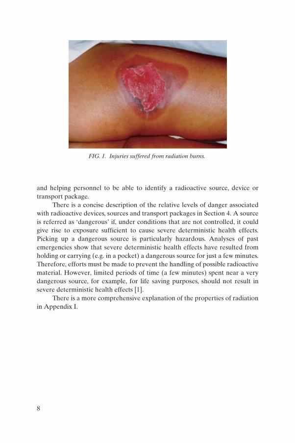
A radioactive source which is not under regulatory control, either because it has never been under regulatory control, or because it has been abandoned, lost, misplaced, stolen or otherwise transferred without proper authorization is known as an “orphan source”. Such sources represent the greatest risk in the case of either an accident or involving malicious use. For example, an incident occurred where a source had been used in a therapy unit in a hospital that has since closed down. No action was taken to manage the source correctly, and after some years the source and associated shielding were stolen by scrap metal collectors. They did not recognize, or did not heed, warning signs and dismantled the shielding and source, causing widespread contamination, injury and illness not only to themselves, but to people with whom they were in contact.
There have been numerous incidents [4–8] where individuals have been exposed to high doses of radiation, either as a result of their own actions or the negligent actions of others, resulting in serious injury and death (see Fig. 1)
Many such incidents have been caused as a result of lack of knowledge about how to identify a radioactive source, either through its appearance or labelling. A new warning label has been developed with the intention of trans-mitting information of potential danger in a better way. The potential for the malicious use of sources has now also been identified, and such use would almost certainly require a high activity radioactive source or sources to be transported or abandoned in a public place.
The objectives of this manual are to help reduce the risk of either of the above by providing a clear guide, explaining the nature of radioactive sources,
7
and helping personnel to be able to identify a radioactive source, device or transport package.
There is a concise description of the relative levels of danger associated with radioactive devices, sources and transport packages in Section 4. A source is referred as ‘dangerous’ if, under conditions that are not controlled, it could give rise to exposure sufficient to cause severe deterministic health effects. Picking up a dangerous source is particularly hazardous. Analyses of past emergencies show that severe deterministic health effects have resulted from holding or carrying (e.g. in a pocket) a dangerous source for just a few minutes. Therefore, efforts must be made to prevent the handling of possible radioactive material. However, limited periods of time (a few minutes) spent near a very dangerous source, for example, for life saving purposes, should not result in severe deterministic health effects [1].
There is a more comprehensive explanation of the properties of radiation in Appendix I.
FIG. 1. Injuries suffered from radiation burns.
8
2. IDENTIFYING A RADIOACTIVE SOURCE, DEVICEOR TRANSPORT PACKAGE WITH AUTHORIZED USE
Radioactive sources, devices and transport packages vary a great deal in their appearance, depending on the specific application for which they may be used. Section 4 provides a more detailed discussion of devices, sources and transport packages.
The primary method of recognizing a radioactive device, source or transport package is by its identification labelling. The following sections provide a brief description of radioactive devices, sources and transport packages and their labelling.
2.1. DEVICES
The machine, instrument or shielded package in which a radioactive source is located during use is referred to as the ‘device’.
Devices vary widely in their appearance according to the amount, type and energy of the radiation from the internal radioactive source, as well as the specific application for which the device is intended.
In general, most devices contain gamma emitting radioactive sources, which are most efficiently shielded by dense metals, such as lead, tungsten or depleted uranium. Therefore, many devices can be characterized as being heavy in relation to their size [9].
Devices may be intentionally portable, such as radiography cameras and road gauges, or they may also be loaded with a source at a dedicated facility and then transported to a permanent place of use. It is quite legitimate, therefore, for a device to be used to transport a source provided the user is authorized to do so and the device is labelled accordingly. In this case, the labelling should correspond both to the system of labelling for transport packages described in the discussion that follows, and to that required for a device. Many devices used for transport of the source feature an ‘overpack’ or shipping crate which is used to protect the device from damage or interference in transit. These may have the appearance of standard industrial packaging with the exception of the transport labelling [3].
Examples of ‘portable’ devices include:
— Gamma radiography projectors;— Moisture density gauges for road building and civil engineering;— X ray fluorescence detectors for material characterization.
9
Examples of devices used as transport packages to move a radioactive source to its place of use include gamma and beta radiation density and thickness gauges, teletherapy heads, blood irradiators and smoke detectors.
All such devices are illustrated in Section 5.
Labelling of a device
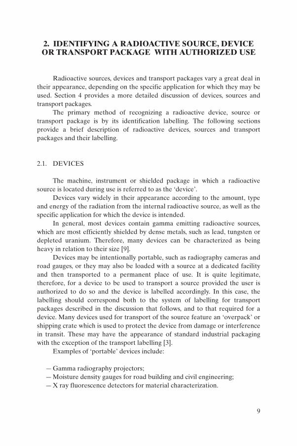
Devices containing radioactive sources should be clearly labelled. Their size means that the labelling is clearer to read and acts as a warning to deter interference. The exact wording on device labels varies according to local regulations but should always include the trefoil symbol, the nuclide and atomic number, and normally the word ‘radioactive’. If possible, the trefoil is represented in black or red on a yellow background (see Fig. 2).
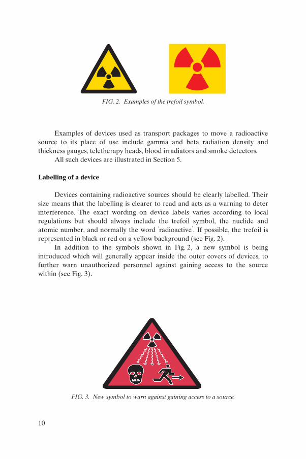
In addition to the symbols shown in Fig. 2, a new symbol is being introduced which will generally appear inside the outer covers of devices, to further warn unauthorized personnel against gaining access to the source within (see Fig. 3).
FIG. 2. Examples of the trefoil symbol.
FIG. 3. New symbol to warn against gaining access to a source.
10
2.2. SOURCES
Most sources are recognizable as stainless steel capsules in the form of a cylinder of varying dimensions. They are normally of stainless steel, which may darken or tarnish with use, particularly when very high activity sources are involved.
In general, if a suspected sealed radioactive source is identified without being located in any shielding, it could be dangerous and should not be approached by untrained personnel without appropriate radiological protection and detection equipment.
Most radioactive sources are rather small, and it is very difficult to read labelling without getting close enough to cause potential injury from the radiation.
It is essential that:
— No attempt be made to read labelling without specialized knowledge or equipment;
— No attempt be made to touch a radioactive source.
Note that the physical size of a source is not an indication of its relative danger.
Sources are illustrated in Section 6.
Labelling of a source
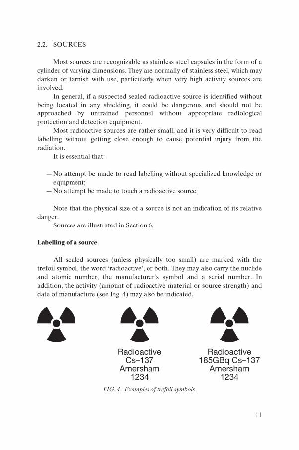
All sealed sources (unless physically too small) are marked with the trefoil symbol, the word ‘radioactive’, or both. They may also carry the nuclide and atomic number, the manufacturer’s symbol and a serial number. In addition, the activity (amount of radioactive material or source strength) and date of manufacture (see Fig. 4) may also be indicated.
RadioactiveCs–137
Amersham1234
Radioactive185GBq Cs–137
Amersham1234
FIG. 4. Examples of trefoil symbols.
11
2.3. TRANSPORT PACKAGES
As with devices, transport packages vary significantly in size, weight and appearance, depending on the activity, type and energy of the radioactive source or sources contained within.
Packages can vary from fin-cooled steel flasks containing lead or depleted uranium shielding and weighing in excess of 5 t for very high activity gamma radioactive sources, to small, disposable cardboard boxes for low activity sources.
Examples of the wide variety of transport packages in use are provided in Section 7.
Labelling of a transport package
The labelling of transport packages generally conforms to international regulatory conventions outlined in the IAEA’s Regulations for the Safe Transport of Radioactive Material [3]. These requirements also apply to devices when they are being used to transport radioactive sources.
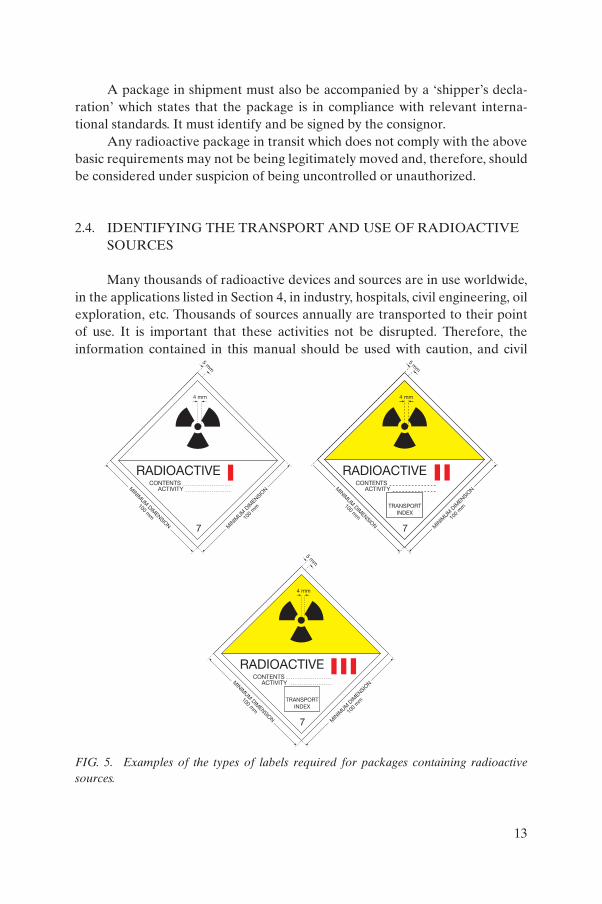
All packages containing radioactive sources, unless containing very low levels of radioactive material (for example, smoke detectors or exempt quantities) must be labelled clearly with one of the types of labels shown in Fig. 5, as a minimum.
The label is chosen according to a combination of the maximum radiation dose rate on the surface of the package and the maximum radiation dose rate at a distance of 1 m from the surface of the package. Category 1 labelling indicates the lowest dose rates while category 3 labelling is associated with the highest dose rates.
Depending on the shielding of the package, the category labels are notindicative of the quantity of radioactive material, type of radiation or hazard of the material. However, the nuclide, mass number and activity must be written on the label. Labels must be placed on two opposite sides of the package. (The ‘categories’ referred to in the context of labelling packages are not to be confused with the IAEA categorization system, which rates radioactive sources according to the level of danger: Category 1 sources are potentially the most dangerous and Category 5 sources are the most unlikely to be dangerous. Section 4.9 provides a more comprehensive explanation of the categories pertaining to source exposure.)
A package is also required to carry the ‘UN number’ and proper shipping name, e.g. “UN2916 radioactive material Type B(U) package”.
12
A package in shipment must also be accompanied by a ‘shipper’s decla-ration’ which states that the package is in compliance with relevant interna-tional standards. It must identify and be signed by the consignor.
Any radioactive package in transit which does not comply with the above basic requirements may not be being legitimately moved and, therefore, should be considered under suspicion of being uncontrolled or unauthorized.
2.4. IDENTIFYING THE TRANSPORT AND USE OF RADIOACTIVE SOURCES
Many thousands of radioactive devices and sources are in use worldwide, in the applications listed in Section 4, in industry, hospitals, civil engineering, oil exploration, etc. Thousands of sources annually are transported to their point of use. It is important that these activities not be disrupted. Therefore, the information contained in this manual should be used with caution, and civil
5 mm
MINIM
UM DIM
ENSION
100 mm
CONTENTS
RADIOACTIVEACTIVITY
7 MIN
IMUM
DIM
ENSION
100
mm
4 mm
7
5 mm
MINIM
UM DIM
ENSION
100 mm
CONTENTS
RADIOACTIVEACTIVITY
MIN
IMUM
DIM
ENSION
100
mm
4 mm
TRANSPORTINDEX
5 mm
MINIM
UM DIM
ENSION
100 mm
CONTENTS
RADIOACTIVEACTIVITY
7 MIN
IMUM
DIM
ENSION
100
mm
4 mm
TRANSPORTINDEX
FIG. 5. Examples of the types of labels required for packages containing radioactive sources.
13

authorities should be notified only if there is reasonable suspicion of uncon-trolled use or transport of a radioactive source, or if a suspected radioactive device, source or transport package is found to be ‘uncontrolled’.
‘Controlled’ use of a radioactive device, source or transport package may be defined as being used for the intended purpose and that has an identifiable owner. If these requirements are not met, then the device, source or transport package may be considered to be ‘uncontrolled’.
The safe use and transport of radioactive devices, sources and packages are regulated by national authorities to protect public health and safety.
Sections 5, 6 and 7 describe the situations in which devices, sealed sources and transport packages would be expected to be found.
If a suspect device, sealed radioactive source or transport package does not fall into the categories of controlled use, storage or transport as described in Sections 5, 6 and 7, and if no authorized owner can be found, then the actions described below should be taken.
Examples of uncontrolled use may include, but are not limited to:
— Any source found unshielded and not located in a device or transport package;
— Any device not in its place of use or authorized storage, or in authorized transit;
— Any device or source found abandoned.
In the event of a device, sealed source or transport package being found in a situation that is suspected to be unauthorized or uncontrolled, or if its transport is suspected to be uncontrolled, actions to be taken are described in Section 3.
3. ACTIONS TO BE TAKEN IF AN UNCONTROLLED SEALED SOURCE, DEVICE OR TRANSPORT PACKAGE
IS FOUND
(1) If a radioactive source, device or transport package is found, the following steps should be observed:
— Do not touch the object.— Evacuate the immediate area and prevent access (secure the area).
14
— Maximize the distance that people are from the object (for guidance, the radiation dose rate and danger is significantly reduced in most cases by retreating a distance of at least 5 m).
— Notify civil authorities, emergency services (rescue services, police) – your local contact details should be readily available.
More details on specific actions can be found in Ref. [1].
(2) Implement any specific procedure or protocol for such an eventand notify civil authorities, bearing in mind the following:
— Only trained personnel who are equipped with suitable radiation detection equipment should approach the suspect object.
— Upon initiation of the response the first responders should perform actions on a scene of emergency according to establish emergency plans [1].
4. USES OF RADIOACTIVE SEALED SOURCESAND DEVICES
The properties of radiation are used in a wide variety of applications. However, in all these applications, the radioactive material is contained within the sealed source and the device allows the radiation to be used in a controlled way.
The application areas for the use of radioactive devices and sources may be broken into six groups:
— Medical uses;— Non-medical irradiation of products;— Gauging systems;— Imaging systems (radiography);— Materials analysis;— Miscellaneous uses.
15
4.1. MEDICAL USES
Radioactive devices and sources are used in the field of medicine for cancer therapy and blood irradiation.
In cancer therapy, a tumour is exposed to radiation either by an external beam passing through the body to the cancer site (teletherapy) or by the temporary or permanent implant of a radiation source inside or close to the tumour (brachytherapy). The action of the radiation kills the cancerous cells leading to the elimination or reduction of the tumour.
Blood may be treated by irradiation prior to transfusion to inhibit lymphocyte proliferation. This minimizes the likelihood of problems with the patient’s immune system in the future.
Radioactive devices used in medical applications are likely, therefore, to be found in:
— Hospital cancer therapy units;— Hospital blood transfusion units and blood storage units.
In addition, short lived radioisotopes are used extensively in medical diagnostics but are of minimal danger and are beyond the scope of this manual.
4.2. NON-MEDICAL IRRADIATION OF PRODUCTS
Radioactive devices and sources are used in the field of materials treatment for:
— Sterilization;— Radiation treatment to alter the properties of a material;— Radiation treatment of pests (e.g. flies) to impede reproduction;— Food irradiation as a means of preserving it.
In sterilization, products which are required to be sterilized (for example, medical devices and surgical dressings) are exposed to a high level of radiation. The radiation dose is carefully controlled to kill any bacteria which may have accidentally entered the packaging during the manufacturing process. The product itself is unaffected by the process.
Materials may be treated by radiation in order to change their properties, for example, a high dose of radiation can be used to cross-link polymer chains in a plastic to strengthen it. Seeds may be irradiated to promote early germination or enhance disease resistance.
16
Radioactive sources are used within a programme to reduce insect pest populations. The Joint FAO/IAEA Division of Nuclear Techniques in Food and Agriculture has worked for many years on developing the sterile insect technique (SIT) for tsetse fly control.
Typically, sources used to treat materials by irradiation have high energy and intensity of radiation, and are contained within the most bulky shielding. For process sterilization, for example, of medical products, the device is effectively a building containing a large shielded room through which the product passes.
Materials treatment facilities may be found in:
— Dedicated sterilization facilities which are factory size units;— Medical device manufacturing industries;— Research laboratories and educational facilities;— Agricultural research facilities.
4.3. GAUGING SYSTEMS
Radioactive devices and sources are used in the field of gauging for:
— Thickness;— Density; — Level.
For thickness gauging, where a sheet of material is being processed through a mill, a radioactive source is placed on one side of the sheet and a detector on the other (see Fig. 6). The amount of radiation transmitted is proportional to the thickness of the material assuming constant density. The signal from the gauging system is fed back into the upstream process control to ensure that the correct thickness is always achieved. The isotope is chosen to have an energy most suited to the relative thickness and density of the strip being measured. The aim is to obtain the optimum attenuation of the radiation in order to provide a high resolution signal to the radiation measurement system [9].
Similarly, the density of a material of known thickness may be evaluated by measuring the amount of radiation which is transmitted through it or reflected from it.
For level gauging, the level of material in a container can be determined using a radiation source and detector. The beam of radiation is passed through the container and when the level of material in the container passes the height
17
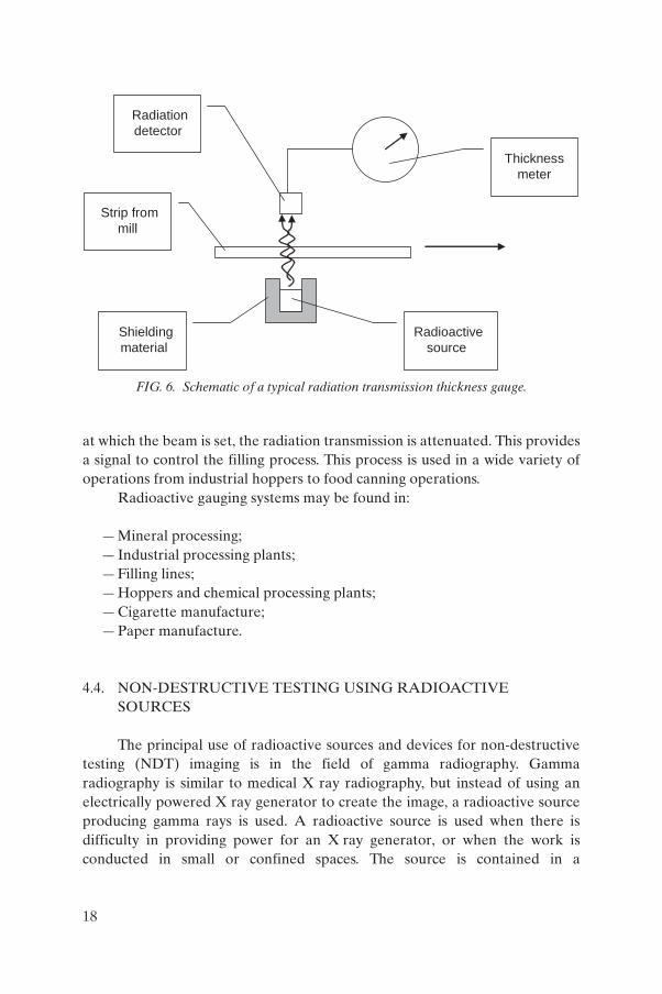
at which the beam is set, the radiation transmission is attenuated. This provides a signal to control the filling process. This process is used in a wide variety of operations from industrial hoppers to food canning operations.
Radioactive gauging systems may be found in:
— Mineral processing;— Industrial processing plants;— Filling lines;— Hoppers and chemical processing plants;— Cigarette manufacture;— Paper manufacture.
4.4. NON-DESTRUCTIVE TESTING USING RADIOACTIVE SOURCES
The principal use of radioactive sources and devices for non-destructive testing (NDT) imaging is in the field of gamma radiography. Gamma radiography is similar to medical X ray radiography, but instead of using an electrically powered X ray generator to create the image, a radioactive source producing gamma rays is used. A radioactive source is used when there is difficulty in providing power for an X ray generator, or when the work is conducted in small or confined spaces. The source is contained in a
Shielding
material Radioactive
source
Strip from
mill
Radiation
detector
Thickness
meter
FIG. 6. Schematic of a typical radiation transmission thickness gauge.
18
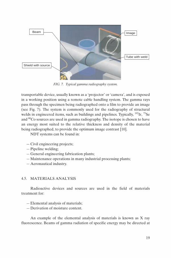
transportable device, usually known as a ‘projector’ or ‘camera’, and is exposed in a working position using a remote cable handling system. The gamma rays pass through the specimen being radiographed onto a film to provide an image (see Fig. 7). The system is commonly used for the radiography of structural welds in engineered items, such as buildings and pipelines. Typically, 192Ir, 75Se and 60Co sources are used in gamma radiography. The isotope is chosen to have an energy most suited to the relative thickness and density of the material being radiographed, to provide the optimum image contrast [10].
NDT systems can be found in:
— Civil engineering projects;— Pipeline welding;— General engineering fabrication plants;— Maintenance operations in many industrial processing plants;— Aeronautical industry.
4.5. MATERIALS ANALYSIS
Radioactive devices and sources are used in the field of materials treatment for:
— Elemental analysis of materials;— Derivation of moisture content.
An example of the elemental analysis of materials is known as X ray fluorescence. Beams of gamma radiation of specific energy may be directed at
Beam
Shield with source
Image
Tube with weld
FIG. 7. Typical gamma radiography system.
19
a metal alloy. These interact with different elements in different ways and the secondary radiation of different energies is ‘reflected’. Analysis of the spectrum of reflected radiation provides a measurement of what the constituent elements are and their relative proportions.
Moisture content and hydrocarbon content in bulk materials and processing lines may be evaluated by measuring the transmission and reflection of neutrons from a neutron radiation source. Neutrons have the same mass as hydrogen atoms and recoil from a collision with a hydrogen atom at much reduced speed. Measurements of the quantity of slowed neutrons recoiled from a bulk material allow the hydrogen content to be evaluated. This can be used to measure water content. In oil exploration, the same technique, combined with other measurements, can be used to evaluate the presence of hydrocarbons in an oil well.
Radioactive sources for materials analysis may be found in:
— Scrap metal processing;— Lead in paint analysis;— On-line analysis in materials processing;— Wood pulp and slurry analysis in the process industry;— Research facilities;— Civil engineering and road building;— Agriculture;— Industrial laboratories;— Oil exploration and production.
4.6. MISCELLANEOUS USES
There are many other applications of radioactive devices and sources not listed here. Some further examples are:
— Power generation using a radioisotope thermoelectric generator;— Smoke detection;— Self-luminous signs;— Gun sights;— Elimination of static electricity;— Lightning prevention.
The above applications are described in Sections 5 and 6.
20
4.7. EXAMPLES OF SEALED RADIOACTIVE SOURCES AND DEVICES
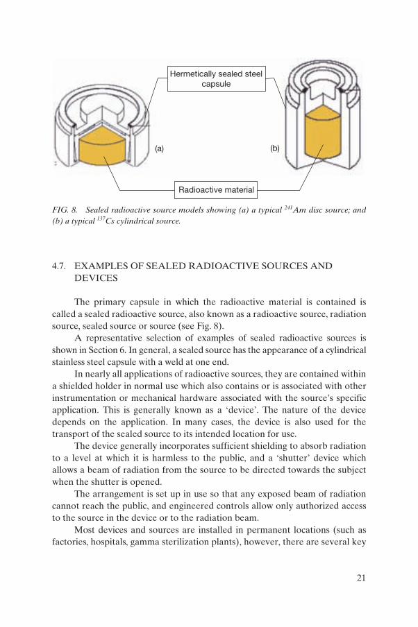
The primary capsule in which the radioactive material is contained is called a sealed radioactive source, also known as a radioactive source, radiation source, sealed source or source (see Fig. 8).
A representative selection of examples of sealed radioactive sources is shown in Section 6. In general, a sealed source has the appearance of a cylindrical stainless steel capsule with a weld at one end.
In nearly all applications of radioactive sources, they are contained within a shielded holder in normal use which also contains or is associated with other instrumentation or mechanical hardware associated with the source’s specific application. This is generally known as a ‘device’. The nature of the device depends on the application. In many cases, the device is also used for the transport of the sealed source to its intended location for use.
The device generally incorporates sufficient shielding to absorb radiation to a level at which it is harmless to the public, and a ‘shutter’ device which allows a beam of radiation from the source to be directed towards the subject when the shutter is opened.
The arrangement is set up in use so that any exposed beam of radiation cannot reach the public, and engineered controls allow only authorized access to the source in the device or to the radiation beam.
Most devices and sources are installed in permanent locations (such as factories, hospitals, gamma sterilization plants), however, there are several key
Hermetically sealed steelcapsule
Radioactive material
(a) (b)
FIG. 8. Sealed radioactive source models showing (a) a typical 241Am disc source; and (b) a typical 137Cs cylindrical source.
21
applications where sources are used for a single task on a site and then moved, in their device or a transport package, to another location. Examples of these applications include gamma radiography and construction moisture density gauging.
Section 5 illustrates a wide range of typical devices.Sources are moved from one location to another either in the device in
which they are to be used, or in shielded transport packages designed specifi-cally for the type of source being transported.
The type of transport package will vary from a steel-cased flask weighing over 5 t, with over 20 cm lead shielding for large sterilization sources, to a cardboard box for sources with very low levels of radiation output, or for radiation that is easily absorbed.
Section 7 illustrates a range of typical transport packages.
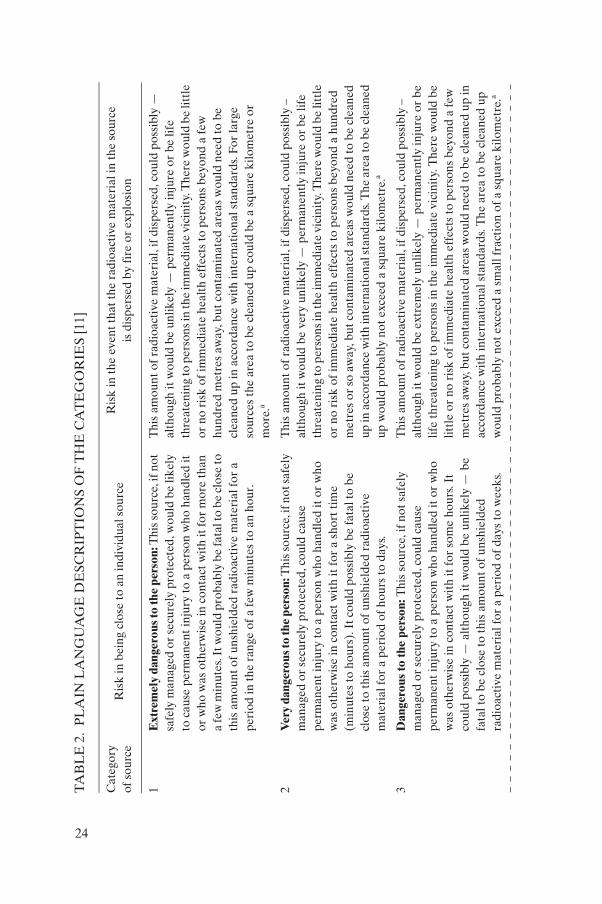
4.8. IAEA CATEGORIES OF RADIOACTIVE SOURCES
The IAEA has developed a system of categorization of radioactive sources [11] to provide a simple, logical means for ranking them based on their potential to cause harm to human health. In addition, it provides a means for grouping the applications in which these sources are used into discrete categories.
In recognition of the fact that human health is of paramount importance, the categorization system is based primarily on the potential for radioactive sources to cause deterministic health effects. The categorization system is therefore based on the concept of ‘dangerous sources’ which are quantified in terms of D-values. The D-value is the radionuclide-specific activity of a source which, if not under control, could cause severe deterministic effects for a range of scenarios that include both external exposure from an unshielded source and inadvertent internal exposure following dispersal (such as fire or explosion) of the source material.
The activity of a radioactive material (A) in a source varies over many orders of magnitude; D-values are therefore used to normalize the range of activities in order to provide a reference in comparing risks – this is done by taking the activity A of the source (in TBq) and dividing it by the D-value for the relevant radionuclide.
In some situations it may be appropriate to catagorize a source on the bases of A/D alone, for example, when the practice for which the source may be used is unknown or not confirmed, as may happen at the time of import or export of the source. However, when the circumstances of use of the source is known, the regulatory body may make a judgement to modify this initial
22

categorization using other information about the source or its use. In some circumstances it may be convenient to assign a category on the basis of the practice in which the source is used (see Table 1).
Within this categorization system, sources in Category 1 are considered to be potentially the most ‘dangerous’ because they can pose a very high risk to human health if not managed safely and securely. An exposure of only a few mintes to an unshielded Category 1 may be fatal. At the lower end of the categorization system, sources in Category 5 are potentially the least dangerous; however, even these sources could give rise to doses in excess of the
TABLE 1. CATEGORIES FOR SOURCES USED IN COMMON PRACTICES [11]
Category Sourcea and practiceActivity ratiob
(A/D)
1 Radioisotope thermoelectric generators (RTGs)IrradiatorsTeletherapy sourcesFixed, multi-beam teletherapy (gamma knife) sources
A/D ≥ 1000
2 Industrial gamma radiography sourcesHigh/medium dose rate brachytherapy sources
1000 > A/D ≥ 10
3 Fixed industrial gauges that incorporate high activity sourcesWell logging gauges
10 > A/D ≥ 1
4 Low dose rate brachytherapy sources (except eye plaques and permanent implants)Industrial gauges that do not incorporate high activity sourcesBone densitometersStatic eliminators
1 > A/D ≥ 0.01
5 Low dose rate brachytherapy eye plaques and permanent implant sourcesX ray fluorescence (XRF) devicesElectron capture devicesMossbauer spectrometry sourcesPositron emission tomography (PET) check sources
0.01 > A/Dand
A > exempt
a Factors other than A/D alone have been taken into consideration in assigning the sources to a category.
b This column can be used to determine the category of a source purely on the basis of A/D. This may be appropriate, for example, if the practice is not known or is not listed, if sources have a short half-life and/or are unsealed, or if sources are aggregated.
23
TA
BL
E 2
. P
LA
IN L
AN
GU
AG
E D
ESC
RIP
TIO
NS
OF
TH
E C
AT
EG
OR
IES
[11]
Cat
egor
y
of s
ourc
eR
isk
in b
eing
clo
se t
o an
indi
vidu
al s
ourc
eR
isk
in th
e ev
ent t
hat t
he r
adio
acti
ve m
ater
ial i
n th
e so
urce
is d
ispe
rsed
by
fire
or
expl
osio
n
1E
xtre
mel
y da
nger
ous
to th
e pe
rson
: Thi
s so
urce
, if n
ot
safe
ly m
anag
ed o
r se
cure
ly p
rote
cted
, wou
ld b
e lik
ely
to c
ause
per
man
ent
inju
ry to
a p
erso
n w
ho h
andl
ed it
or
who
was
oth
erw
ise
in c
onta
ct w
ith
it fo
r m
ore
than
a
few
min
utes
. It w
ould
pro
babl
y be
fata
l to
be c
lose
to
this
am
ount
of
unsh
ield
ed r
adio
acti
ve m
ater
ial f
or a
pe
riod
in t
he r
ange
of a
few
min
utes
to
an h
our.
Thi
s am
ount
of
radi
oact
ive
mat
eria
l, if
dis
pers
ed, c
ould
pos
sibl
y —
al
thou
gh it
wou
ld b
e un
likel
y —
per
man
entl
y in
jure
or
be li
fe
thre
aten
ing
to p
erso
ns in
the
imm
edia
te v
icin
ity.
The
re w
ould
be
littl
e or
no
risk
of i
mm
edia
te h
ealt
h ef
fect
s to
per
sons
bey
ond
a fe
w
hund
red
met
res
away
, but
con
tam
inat
ed a
reas
wou
ld n
eed
to b
e cl
eane
d up
in a
ccor
danc
e w
ith
inte
rnat
iona
l sta
ndar
ds. F
or la
rge
sour
ces
the
area
to
be c
lean
ed u
p co
uld
be a
squ
are
kilo
met
re o
r m
ore.
a
2V
ery
dang
erou
s to
the
pers
on: T
his s
ourc
e, if
not
safe
ly
man
aged
or
secu
rely
pro
tect
ed, c
ould
cau
se
perm
anen
t in
jury
to a
per
son
who
han
dled
it o
r w
ho
was
oth
erw
ise
in c
onta
ct w
ith
it fo
r a
shor
t tim
e (m
inut
es to
hou
rs).
It c
ould
pos
sibl
y be
fata
l to
be
clos
e to
thi
s am
ount
of u
nshi
elde
d ra
dioa
ctiv
e m
ater
ial f
or a
per
iod
of h
ours
to d
ays.
Thi
s am
ount
of
radi
oact
ive
mat
eria
l, if
dis
pers
ed, c
ould
pos
sibl
y –
alth
ough
it w
ould
be
very
unl
ikel
y —
per
man
entl
y in
jure
or
be li
fe
thre
aten
ing
to p
erso
ns in
the
imm
edia
te v
icin
ity.
The
re w
ould
be
littl
e or
no
risk
of i
mm
edia
te h
ealt
h ef
fect
s to
per
sons
bey
ond
a hu
ndre
d m
etre
s or
so
away
, but
con
tam
inat
ed a
reas
wou
ld n
eed
to b
e cl
eane
d up
in a
ccor
danc
e w
ith
inte
rnat
iona
l sta
ndar
ds. T
he a
rea
to b
e cl
eane
d up
wou
ld p
roba
bly
not e
xcee
d a
squa
re k
ilom
etre
.a
3D
ange
rous
to th
e pe
rson
: Thi
s so
urce
, if n
ot s
afel
y m
anag
ed o
r se
cure
ly p
rote
cted
, cou
ld c
ause
pe
rman
ent
inju
ry to
a p
erso
n w
ho h
andl
ed it
or
who
w
as o
ther
wis
e in
con
tact
wit
h it
for
som
e ho
urs.
It
coul
d po
ssib
ly —
alt
houg
h it
wou
ld b
e un
likel
y —
be
fata
l to
be c
lose
to
this
am
ount
of u
nshi
elde
d ra
dioa
ctiv
e m
ater
ial f
or a
per
iod
of d
ays
to w
eeks
.
Thi
s am
ount
of
radi
oact
ive
mat
eria
l, if
dis
pers
ed, c
ould
pos
sibl
y –
alth
ough
it w
ould
be
extr
emel
y un
likel
y —
per
man
entl
y in
jure
or
be
life
thre
aten
ing
to p
erso
ns in
the
imm
edia
te v
icin
ity.
The
re w
ould
be
littl
e or
no
risk
of
imm
edia
te h
ealt
h ef
fect
s to
per
sons
bey
ond
a fe
w
met
res
away
, but
con
tam
inat
ed a
reas
wou
ld n
eed
to b
e cl
eane
d up
in
acco
rdan
ce w
ith
inte
rnat
iona
l sta
ndar
ds. T
he a
rea
to b
e cl
eane
d up
w
ould
pro
babl
y no
t exc
eed
a sm
all f
ract
ion
of a
squ
are
kilo
met
re.a
24
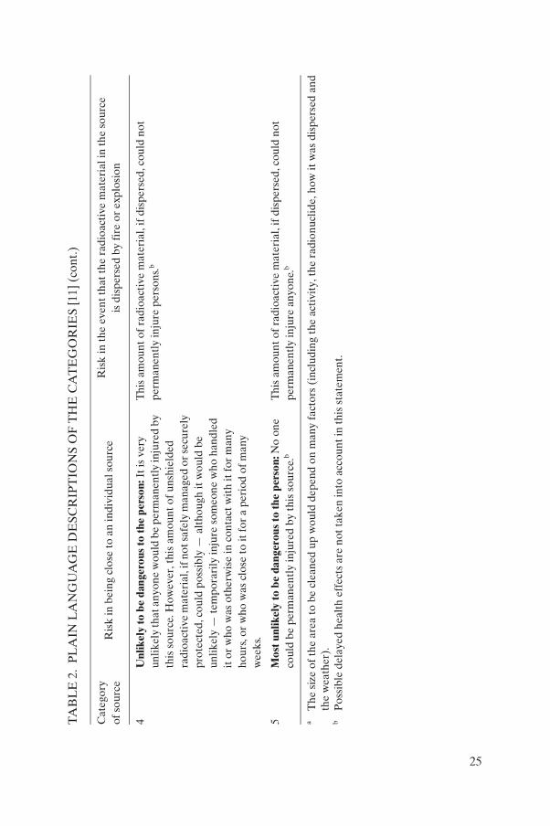
4U
nlik
ely
to b
e da
nger
ous
to th
e pe
rson
: It i
s ve
ry
unlik
ely
that
any
one
wou
ld b
e pe
rman
entl
y in
jure
d by
th
is s
ourc
e. H
owev
er, t
his
amou
nt o
f un
shie
lded
ra
dioa
ctiv
e m
ater
ial,
if n
ot s
afel
y m
anag
ed o
r se
cure
ly
prot
ecte
d, c
ould
pos
sibl
y —
alt
houg
h it
wou
ld b
e un
likel
y —
tem
pora
rily
inju
re s
omeo
ne w
ho h
andl
ed
it o
r w
ho w
as o
ther
wis
e in
con
tact
wit
h it
for
man
y ho
urs,
or w
ho w
as c
lose
to it
for
a p
erio
d of
man
y w
eeks
.
Thi
s am
ount
of
radi
oact
ive
mat
eria
l, if
dis
pers
ed, c
ould
not
pe
rman
entl
y in
jure
per
sons
.b
5M
ost u
nlik
ely
to b
e da
nger
ous
to th
e pe
rson
: No
one
coul
d be
per
man
entl
y in
jure
d by
thi
s so
urce
.bT
his
amou
nt o
f ra
dioa
ctiv
e m
ater
ial,
if d
ispe
rsed
, cou
ld n
ot
perm
anen
tly
inju
re a
nyon
e.b
aT
he s
ize
of t
he a
rea
to b
e cl
eane
d up
wou
ld d
epen
d on
man
y fa
ctor
s (i
nclu
ding
the
act
ivit
y, t
he r
adio
nucl
ide,
how
it w
as d
ispe
rsed
and
th
e w
eath
er).
bP
ossi
ble
dela
yed
heal
th e
ffec
ts a
re n
ot t
aken
into
acc
ount
in th
is s
tate
men
t.
TA
BL
E 2
. P
LA
IN L
AN
GU
AG
E D
ESC
RIP
TIO
NS
OF
TH
E C
AT
EG
OR
IES
[11]
(co
nt.)
Cat
egor
y
of s
ourc
eR
isk
in b
eing
clo
se t
o an
indi
vidu
al s
ourc
eR
isk
in th
e ev
ent t
hat t
he r
adio
acti
ve m
ater
ial i
n th
e so
urce
is d
ispe
rsed
by
fire
or
expl
osio
n
25
dose limits if not properly controlled, and therefore need to be kept under appropriate regulatory control.
A detailed and comprehensive description of the categories for sources may be found in Ref. [11].
Throughout Sections 5 and 6, sources and devices are categorized according to their potential to cause harm, as described in this outline.
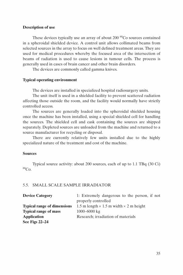
5. EXAMPLES OF RADIOACTIVE DEVICES
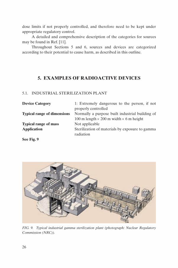
5.1. INDUSTRIAL STERILIZATION PLANT
Device Category 1: Extremely dangerous to the person, if not properly controlled
Typical range of dimensions Normally a purpose built industrial building of 100 m length × 200 m width × 6 m height
Typical range of mass Not applicableApplication Sterilization of materials by exposure to gamma
radiationSee Fig. 9
FIG. 9. Typical industrial gamma sterilization plant (photograph: Nuclear Regulatory Commission (NRC)).
26
Description of use
The gamma sterilization plant is not strictly a device. It is a shielded building in which a large number of 60Co sources are housed in an array.
The product requiring gamma sterilization is put into the shielded area and exposed to the sources for the period required to deliver the gamma dose required to kill bacteria.
Typically sources are exposed in the shielded building during the irradiation process, but are then lowered by remote control into a pit or water filled pond to provide shielding if access to the shielded room is required.
The product may be loaded by batch into the shielded room, and the sources remotely removed from the pit or pond to irradiate the product, or sources may be left semi-permanently exposed, and the product moved through the shielded room on a conveyor system.
Access of personnel to the shielded room is strictly controlled to minimize the possibility of exposure to the sources.
Typical operating environment
Irradiation plants are generally situated on industrial sites and perform contract irradiation of product for a wide range of applications, mostly involving the irradiation of medical devices, but also may be used for foodstuffs and other applications.
Sources are transferred into and out of irradiators in specialized transport containers, where they are loaded by specialized personnel.
Sources
A typical irradiation facility will contain up to 185 PBq (5 MCi) 60Co.
5.2. TELETHERAPY MACHINE
Device Category 1: Extremely dangerous to the person, if not properly controlled
Typical range of dimensions Teletherapy head holding the source: 300–600 mm diameter × 300–600 mm length; Whole device: 4 m length × 2 m width × 3 m height
Typical range of mass Teletherapy head holding the source: 200–500 kg Whole device 500–1000 kg
Application Medical therapy
27
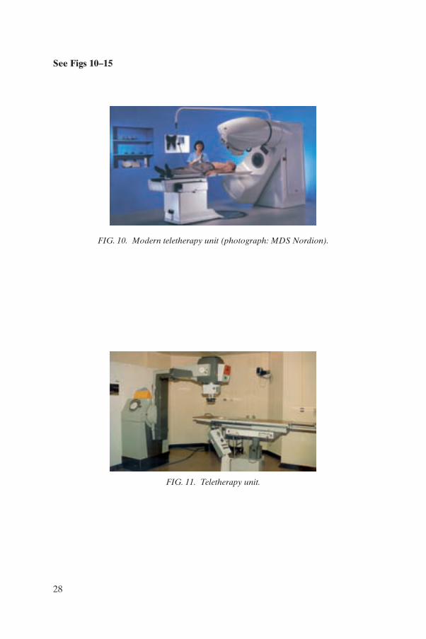
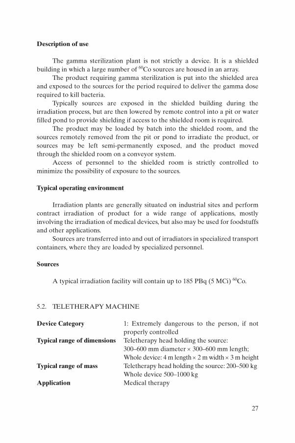
See Figs 10–15
FIG. 10. Modern teletherapy unit (photograph: MDS Nordion).
FIG. 11. Teletherapy unit.
28
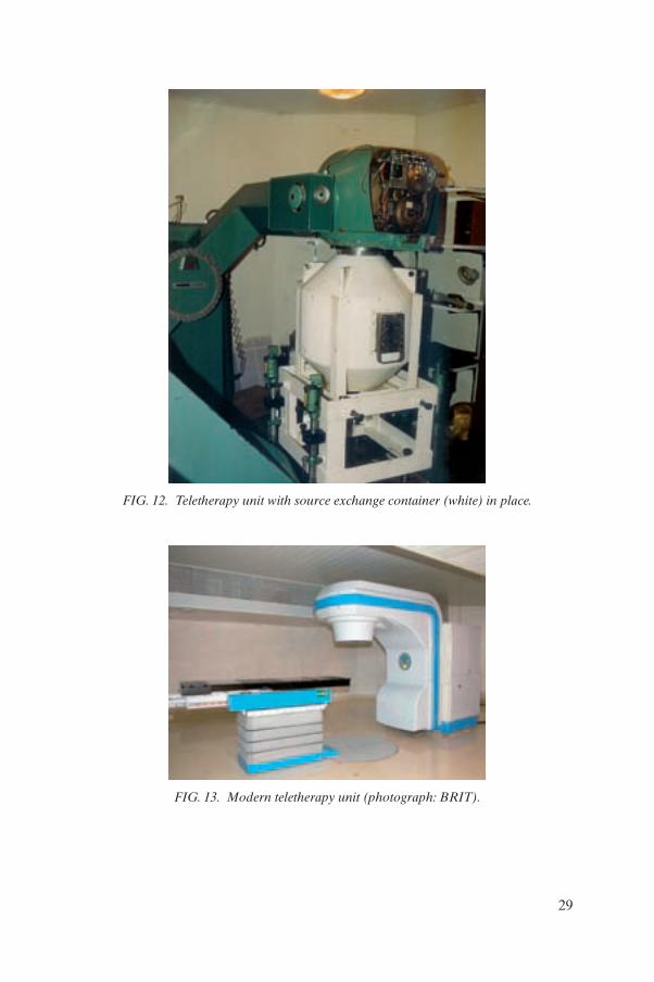
FIG. 12. Teletherapy unit with source exchange container (white) in place.
FIG. 13. Modern teletherapy unit (photograph: BRIT).
29
Description of use
These devices typically use a single 60Co source. They are used for cancer therapy by projecting a beam of high energy radiation focused onto a tumour.
The radioactive source is securely located in the heavy shielded housing at the end of the rotating arm. The beam of radiation from the source is exposed when a shutter is opened during use.
The shielded housing may be demounted from the rotating arm, and shipped to a specialized location for the replacement of a depleted source, or a source transfer may be effected in situ, using a special transport container to
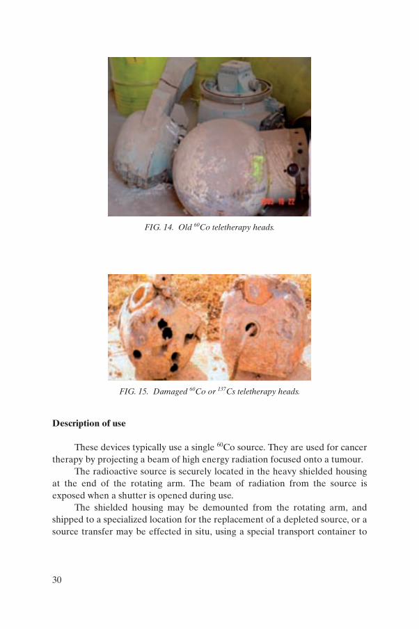
FIG. 14. Old 60Co teletherapy heads.
FIG. 15. Damaged 60Co or 137Cs teletherapy heads.
30
deliver and install the new source and remove the depleted source in a single operation.
Typical operating environment
These devices are installed in many cancer therapy units in hospitals around the world.
The unit itself is used in a shielded facility to prevent the beam of radiation affecting those outside the room, and the facility would normally have strictly controlled access.
Due to the very high activity of the sources used, very specialized shielded equipment and highly trained personnel only can perform such operations.
When units are decommissioned, the shielded housing, complete with the source, is sometimes removed and stored and the rest of the unit scrapped.
The high activity of the sources used makes these units some of the most potentially hazardous devices.
Sources
Source activity: up to 370 TBq (10 kCi) 60Co.A strictly limited number of machines have been supplied using 137Cs
sources.
5.3. BLOOD IRRADIATOR
Device Category 1: Extremely dangerous to the person, if not properly controlled
Typical range of dimensions 1 m length × 1 m width × 1.5 m heightTypical range of mass 1500–3500 kgApplication Medical; irradiation of bloodSee Figs 16–19
31
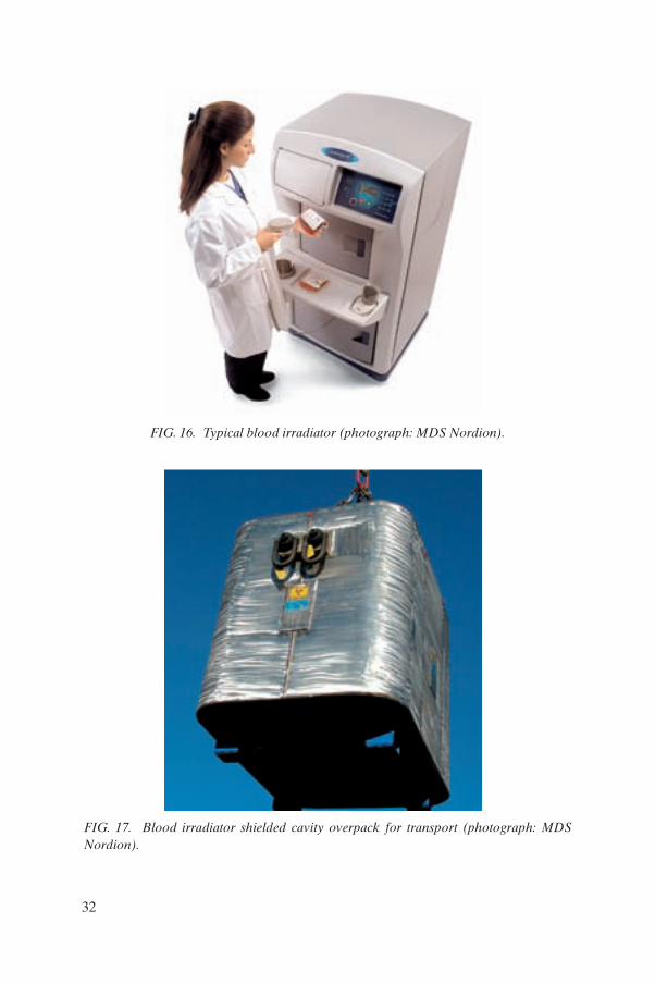
FIG. 16. Typical blood irradiator (photograph: MDS Nordion).
FIG. 17. Blood irradiator shielded cavity overpack for transport (photograph: MDSlNordion).
32
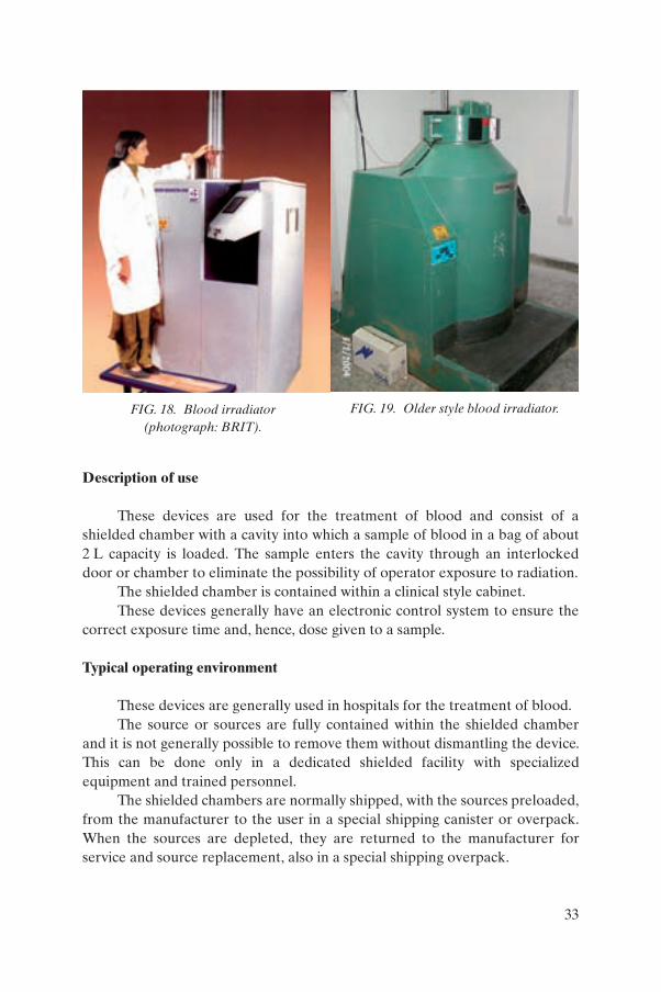
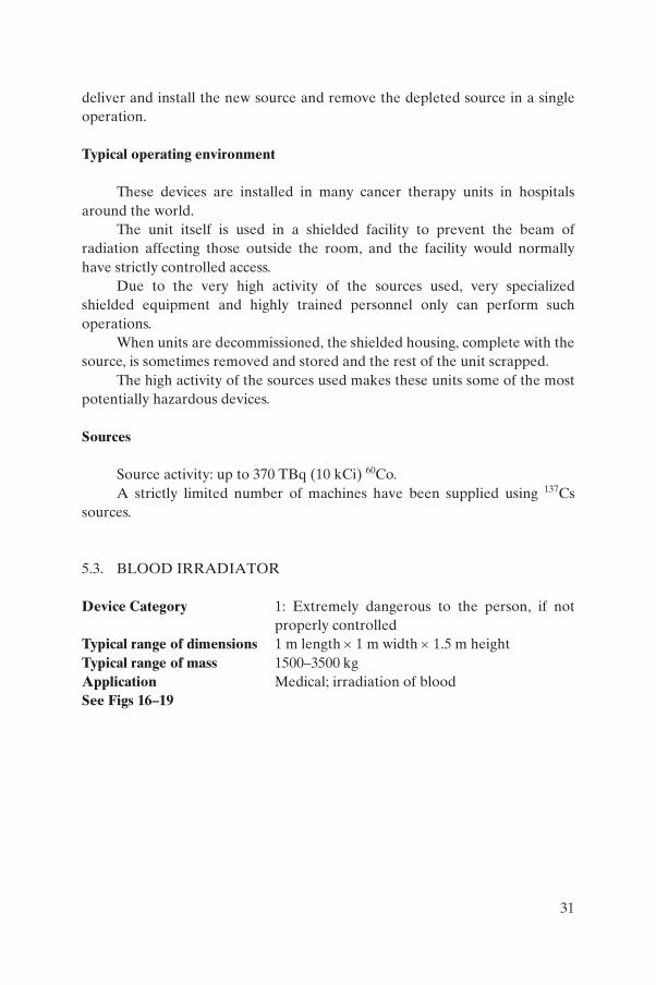
Description of use
These devices are used for the treatment of blood and consist of a shielded chamber with a cavity into which a sample of blood in a bag of about 2 L capacity is loaded. The sample enters the cavity through an interlocked door or chamber to eliminate the possibility of operator exposure to radiation.
The shielded chamber is contained within a clinical style cabinet. These devices generally have an electronic control system to ensure the
correct exposure time and, hence, dose given to a sample.
Typical operating environment
These devices are generally used in hospitals for the treatment of blood. The source or sources are fully contained within the shielded chamber
and it is not generally possible to remove them without dismantling the device. This can be done only in a dedicated shielded facility with specialized equipment and trained personnel.
The shielded chambers are normally shipped, with the sources preloaded, from the manufacturer to the user in a special shipping canister or overpack. When the sources are depleted, they are returned to the manufacturer for service and source replacement, also in a special shipping overpack.
FIG. 18. Blood irradiator (photograph: BRIT).
FIG. 19. Older style blood irradiator.
33
Sources
Typical source activity: up to 250 TBq (7 kCi) 137Cs; up to 25 TBq (7 kCi) 60Co.
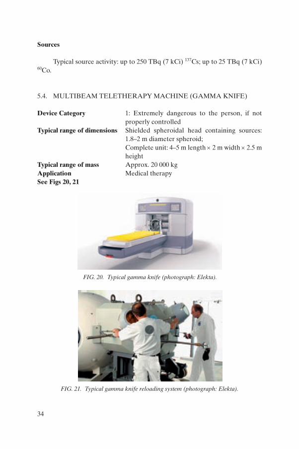
5.4. MULTIBEAM TELETHERAPY MACHINE (GAMMA KNIFE)
Device Category 1: Extremely dangerous to the person, if not properly controlled
Typical range of dimensions Shielded spheroidal head containing sources: 1.8–2 m diameter spheroid; Complete unit: 4–5 m length × 2 m width × 2.5 m height
Typical range of mass Approx. 20 000 kgApplication Medical therapySee Figs 20, 21
FIG. 20. Typical gamma knife (photograph: Elekta).
FIG. 21. Typical gamma knife reloading system (photograph: Elekta).
34
Description of use
These devices typically use an array of about 200 60Co sources contained in a spheroidal shielded device. A control unit allows collimated beams from selected sources in the array to focus on well defined treatment areas. They are used for medical procedures whereby the focused area of the intersection of beams of radiation is used to cause lesions in tumour cells. The process is generally used in cases of brain cancer and other brain disorders.
The devices are commonly called gamma knives.
Typical operating environment
The devices are installed in specialized hospital radiosurgery units.The unit itself is used in a shielded facility to prevent scattered radiation
affecting those outside the room, and the facility would normally have strictly controlled access.
The sources are generally loaded into the spheroidal shielded housing once the machine has been installed, using a special shielded cell for handling the sources. The shielded cell and cask containing the sources are shipped separately. Depleted sources are unloaded from the machine and returned to a source manufacturer for recycling or disposal.
There are currently relatively few units installed due to the highly specialized nature of the treatment and cost of the machine.
Sources
Typical source activity: about 200 sources, each of up to 1.1 TBq (30 Ci) 60Co.
5.5. SMALL SCALE SAMPLE IRRADIATOR
Device Category 1: Extremely dangerous to the person, if not properly controlled
Typical range of dimensions 1.5 m length × 1.5 m width × 2 m heightTypical range of mass 1000–6000 kgApplication Research; irradiation of materialsSee Figs 22–24
35
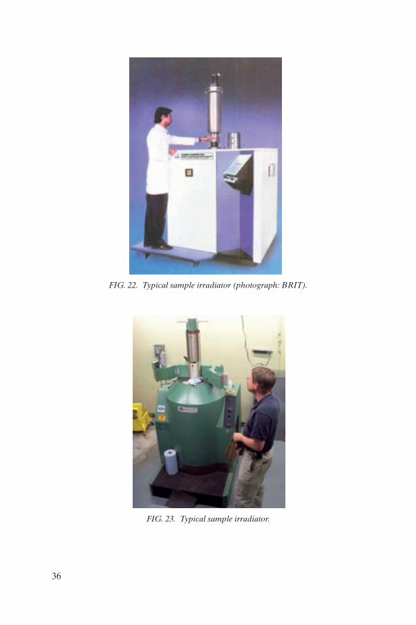
FIG. 22. Typical sample irradiator (photograph: BRIT).
FIG. 23. Typical sample irradiator.
36
Description of use
These devices typically use one or more 60Co sources. The device consists of a shielded chamber with the radioactive source or
sources permanently located inside. Samples for irradiation are loaded into the chamber through a revolving shielded door or interlocked access to prevent any possibility of accidental exposure of the operator.
The shielded chamber is contained within a clinical style cabinet. Modern devices generally have an electronic control system to ensure the
correct exposure time and, hence, dose given to a sample.
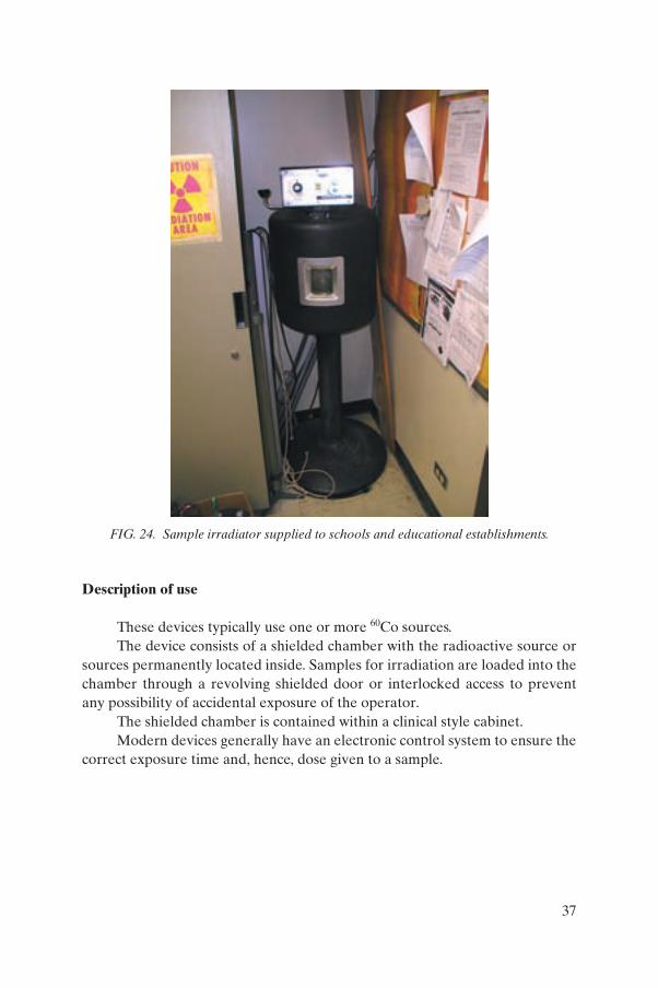
FIG. 24. Sample irradiator supplied to schools and educational establishments.
37
Typical operating environment
These devices are generally used in research laboratories, although smaller types used to be more widely supplied to schools and educational establishments in some countries.
The devices are used for the irradiation of samples of tissue, plant matter and other materials.
The source or sources are fully contained within the shielded chamber and it is not generally possible to remove them without dismantling the device. This can be done only within a dedicated shielded facility with specialized equipment and trained personnel.
The devices are normally shipped, with the sources preloaded, from the manufacturer to the user in a special overpack. When the sources have depleted, they are returned to the manufacturer for service and source replacement, also in a special shipping overpack.
Sources
Typical source activity: 70 TBq (2 kCi) to 900 TBq (25 kCi) 60Co.
5.6. SEED IRRADIATOR
Device Category 1: Extremely dangerous to the person, if not properly controlled
Typical range of dimensions 1.5 m length × 1.5 m width × 2 m height when dismounted from transport device
Typical range of mass 3000–6000 kg when dismounted from transport device
Application Agricultural — irradiation of plant materialsSee Figs 25–27
38
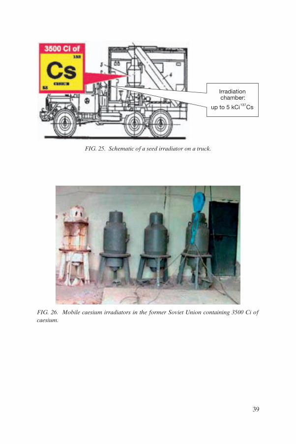
Irradiation chamber:
up to 5 kCi 137Cs
FIG. 25. Schematic of a seed irradiator on a truck.
FIG. 26. Mobile caesium irradiators in the former Soviet Union containing 3500 Ci of caesium.
39
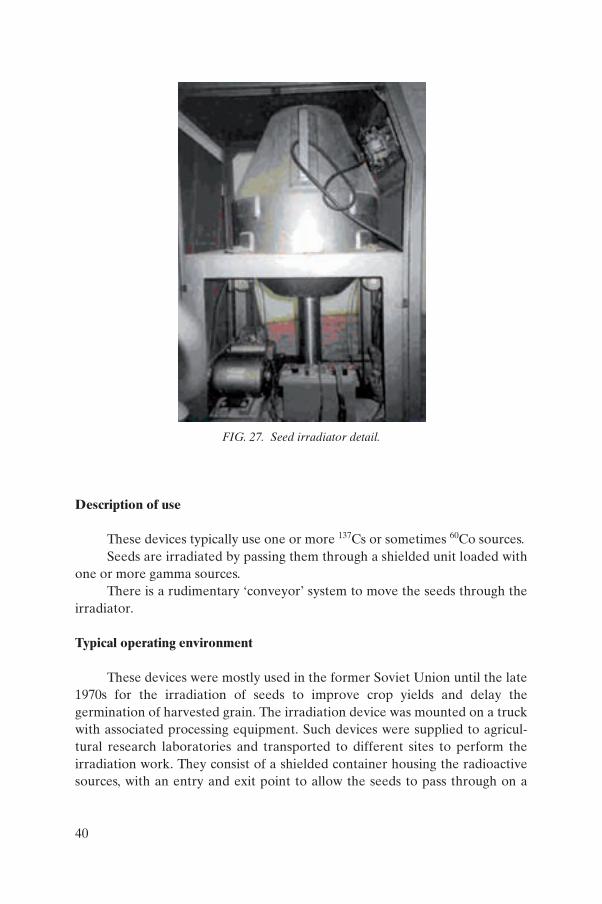
Description of use
These devices typically use one or more 137Cs or sometimes 60Co sources. Seeds are irradiated by passing them through a shielded unit loaded with
one or more gamma sources.There is a rudimentary ‘conveyor’ system to move the seeds through the
irradiator.
Typical operating environment
These devices were mostly used in the former Soviet Union until the late 1970s for the irradiation of seeds to improve crop yields and delay the germination of harvested grain. The irradiation device was mounted on a truck with associated processing equipment. Such devices were supplied to agricul-tural research laboratories and transported to different sites to perform the irradiation work. They consist of a shielded container housing the radioactive sources, with an entry and exit point to allow the seeds to pass through on a
FIG. 27. Seed irradiator detail.
40
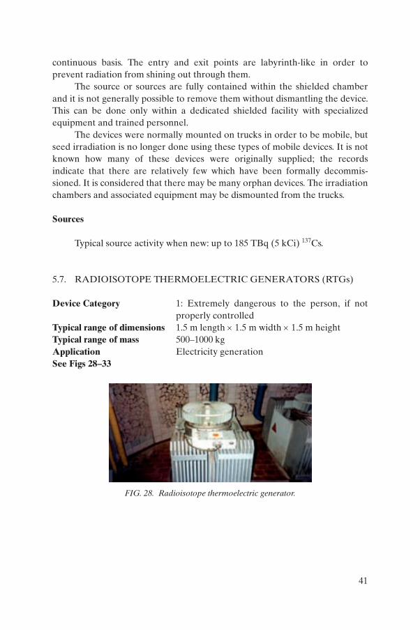
continuous basis. The entry and exit points are labyrinth-like in order to prevent radiation from shining out through them.
The source or sources are fully contained within the shielded chamber and it is not generally possible to remove them without dismantling the device. This can be done only within a dedicated shielded facility with specialized equipment and trained personnel.
The devices were normally mounted on trucks in order to be mobile, but seed irradiation is no longer done using these types of mobile devices. It is not known how many of these devices were originally supplied; the records indicate that there are relatively few which have been formally decommis-sioned. It is considered that there may be many orphan devices. The irradiation chambers and associated equipment may be dismounted from the trucks.
Sources
Typical source activity when new: up to 185 TBq (5 kCi) 137Cs.
5.7. RADIOISOTOPE THERMOELECTRIC GENERATORS (RTGs)
Device Category 1: Extremely dangerous to the person, if not properly controlled
Typical range of dimensions 1.5 m length × 1.5 m width × 1.5 m height Typical range of mass 500–1000 kgApplication Electricity generationSee Figs 28–33
FIG. 28. Radioisotope thermoelectric generator.
41
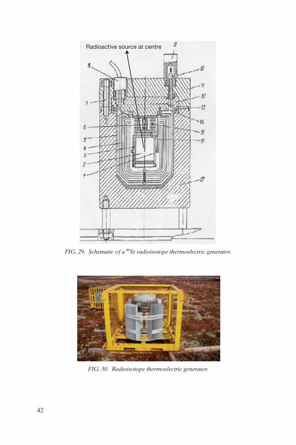
Radioactive source at centre �
FIG. 29. Schematic of a 90Sr radioisotope thermoelectric generator.
FIG. 30. Radioisotope thermoelectric generator.
42
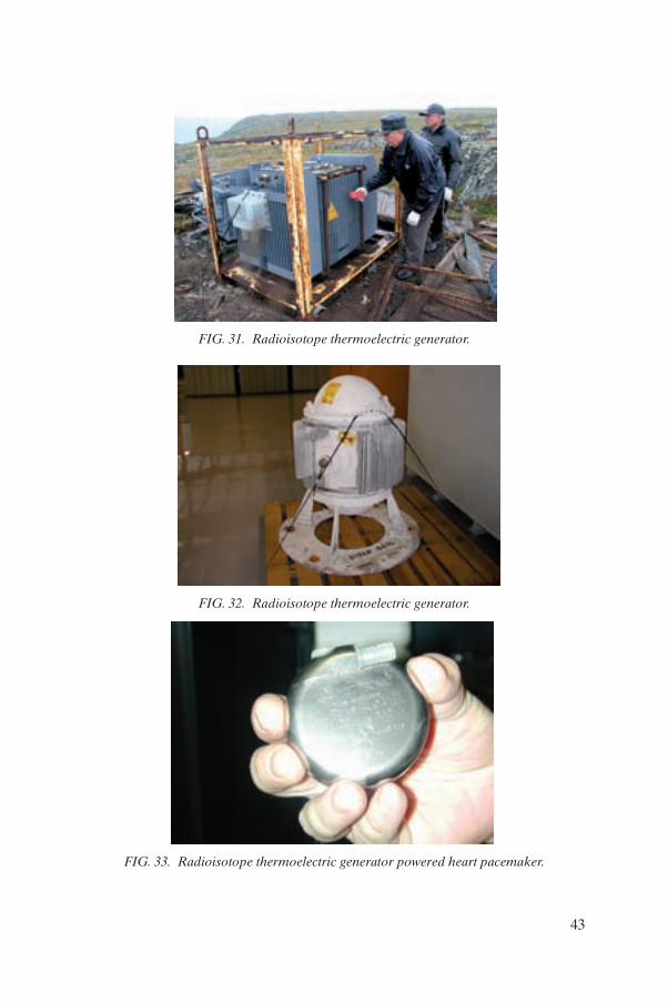
FIG. 31. Radioisotope thermoelectric generator.
FIG. 32. Radioisotope thermoelectric generator.
FIG. 33. Radioisotope thermoelectric generator powered heart pacemaker.
43
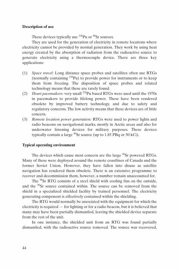
Description of use
These devices typically use 238Pu or 90Sr sources.They are used for the generation of electricity in remote locations where
electricity cannot be provided by normal generation. They work by using heat energy created by the absorption of radiation from the radioactive source to generate electricity using a thermocouple device. There are three key applications:
(1) Space travel: Long distance space probes and satellites often use RTGs (normally containing 238Pu) to provide power for instruments or to keep them from freezing. The disposition of space probes and related technology means that these are rarely found.
(2) Heart pacemakers: very small 238Pu based RTGs were used until the 1970s in pacemakers to provide lifelong power. These have been rendered obsolete by improved battery technology, and due to safety and regulatory concerns. The low activity means that these devices are of little concern.
(3) Remote location power generation: RTGs were used to power lights and radio beacons on navigational marks, mostly in Arctic areas and also for underwater listening devices for military purposes. These devices typically contain a large 90Sr source (up to 1.85 PBq or 50 kCi).
Typical operating environment
The devices which cause most concern are the large 90Sr powered RTGs. Many of these were deployed around the remote coastlines of Canada and the former Soviet Union. However, they have fallen into disuse as satellite navigation has rendered them obsolete. There is an extensive programme to recover and decommission them, however, a number remain unaccounted for.
The 90Sr RTG consists of a steel shield with cooling fins on the outside, and the 90Sr source contained within. The source can be removed from the shield in a specialized shielded facility by trained personnel. The electricity generating component is effectively contained within the shielding.
The RTG would normally be associated with the equipment for which the electricity is required — for lighting or for a radio beacon, but it is believed that many may have been partially dismantled, leaving the shielded device separate from the rest of the unit.
In one instance, the shielded unit from an RTG was found partially dismantled, with the radioactive source removed. The source was recovered,
44
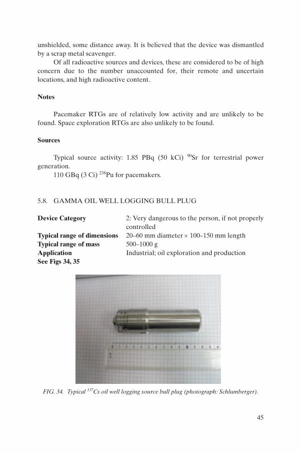
unshielded, some distance away. It is believed that the device was dismantled by a scrap metal scavenger.
Of all radioactive sources and devices, these are considered to be of high concern due to the number unaccounted for, their remote and uncertain locations, and high radioactive content.
Notes
Pacemaker RTGs are of relatively low activity and are unlikely to be found. Space exploration RTGs are also unlikely to be found.
Sources
Typical source activity: 1.85 PBq (50 kCi) 90Sr for terrestrial power generation.
110 GBq (3 Ci) 238Pu for pacemakers.
5.8. GAMMA OIL WELL LOGGING BULL PLUG
Device Category 2: Very dangerous to the person, if not properly controlled
Typical range of dimensions 20–60 mm diameter × 100–150 mm lengthTypical range of mass 500–1000 gApplication Industrial; oil exploration and productionSee Figs 34, 35
FIG. 34. Typical 137Cs oil well logging source bull plug (photograph: Schlumberger).
45
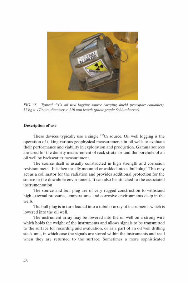
Description of use
These devices typically use a single 137Cs source. Oil well logging is the operation of taking various geophysical measurements in oil wells to evaluate their performance and viability in exploration and production. Gamma sources are used for the density measurement of rock strata around the borehole of an oil well by backscatter measurement.
The source itself is usually constructed in high strength and corrosion resistant metal. It is then usually mounted or welded into a ‘bull plug’. This may act as a collimator for the radiation and provides additional protection for the source in the downhole environment. It can also be attached to the associated instrumentation.
The source and bull plug are of very rugged construction to withstand high external pressures, temperatures and corrosive environments deep in the wells.
The bull plug is in turn loaded into a tubular array of instruments which is lowered into the oil well.
The instrument array may be lowered into the oil well on a strong wire which holds the weight of the instruments and allows signals to be transmitted to the surface for recording and evaluation, or as a part of an oil well drilling stack unit, in which case the signals are stored within the instruments and read when they are returned to the surface. Sometimes a more sophisticated
FIG. 35. Typical 137Cs oil well logging source carrying shield (transport container), 37 kg × 170 mm diameter × 210 mm length (photograph: Schlumberger).
46
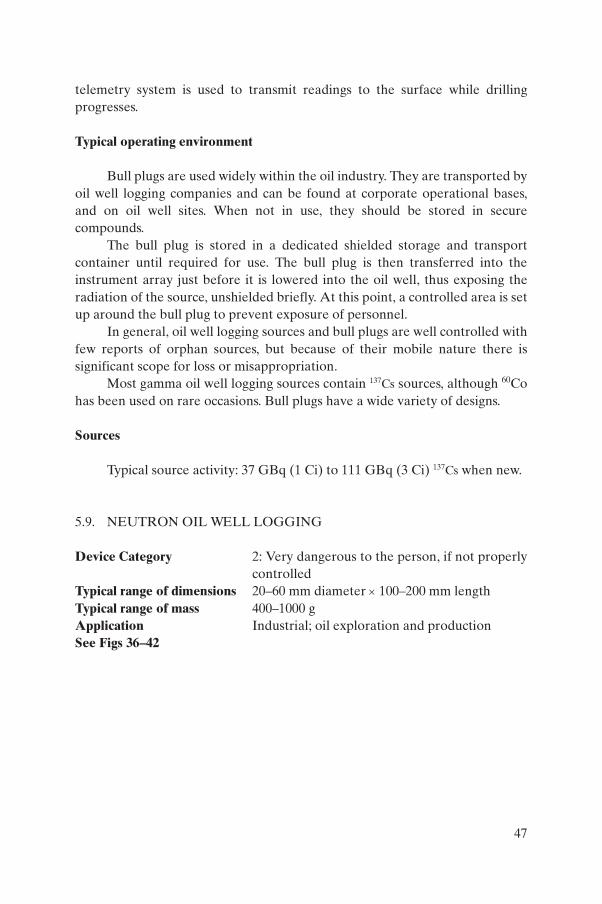
telemetry system is used to transmit readings to the surface while drilling progresses.
Typical operating environment
Bull plugs are used widely within the oil industry. They are transported by oil well logging companies and can be found at corporate operational bases, and on oil well sites. When not in use, they should be stored in secure compounds.
The bull plug is stored in a dedicated shielded storage and transport container until required for use. The bull plug is then transferred into the instrument array just before it is lowered into the oil well, thus exposing the radiation of the source, unshielded briefly. At this point, a controlled area is set up around the bull plug to prevent exposure of personnel.
In general, oil well logging sources and bull plugs are well controlled with few reports of orphan sources, but because of their mobile nature there is significant scope for loss or misappropriation.
Most gamma oil well logging sources contain 137Cs sources, although 60Co has been used on rare occasions. Bull plugs have a wide variety of designs.
Sources
Typical source activity: 37 GBq (1 Ci) to 111 GBq (3 Ci) 137Cs when new.
5.9. NEUTRON OIL WELL LOGGING
Device Category 2: Very dangerous to the person, if not properly controlled
Typical range of dimensions 20–60 mm diameter × 100–200 mm lengthTypical range of mass 400–1000 gApplication Industrial; oil exploration and productionSee Figs 36–42
47
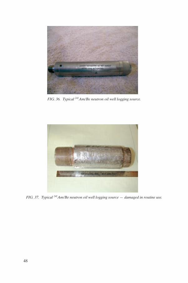
FIG. 36. Typical 241Am/Be neutron oil well logging source.
FIG. 37. Typical 241Am/Be neutron oil well logging source — damaged in routine use.
48
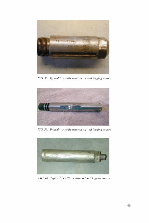
FIG. 38. Typical 241Am/Be neutron oil well logging source.
FIG. 39. Typical 241Am/Be neutron oil well logging source.
FIG. 40. Typical 238Pu/Be neutron oil well logging source.
49
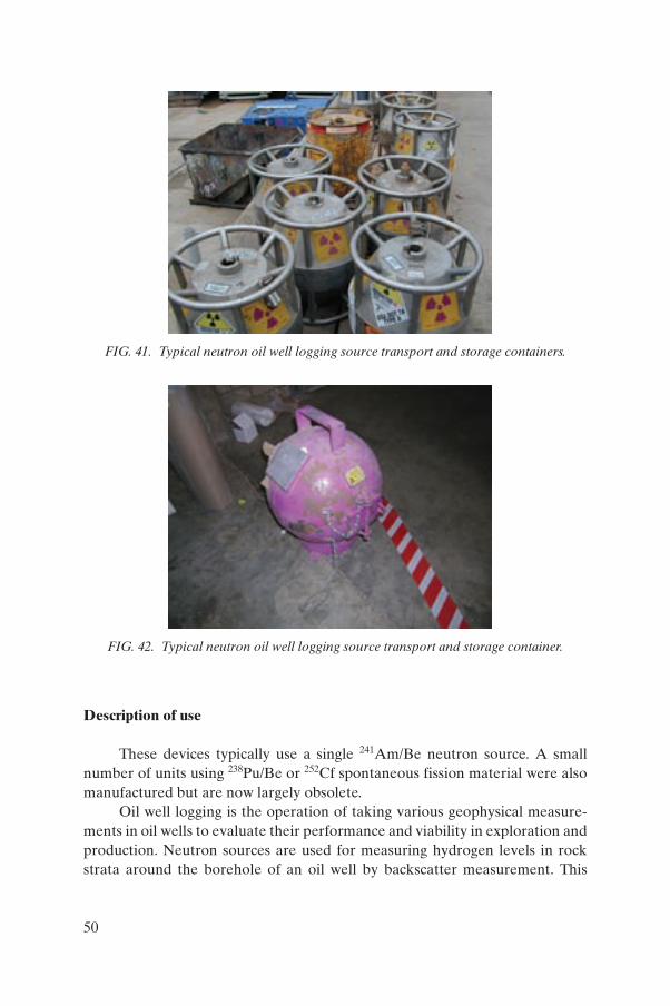
Description of use
These devices typically use a single 241Am/Be neutron source. A small number of units using 238Pu/Be or 252Cf spontaneous fission material were also manufactured but are now largely obsolete.
Oil well logging is the operation of taking various geophysical measure-ments in oil wells to evaluate their performance and viability in exploration and production. Neutron sources are used for measuring hydrogen levels in rock strata around the borehole of an oil well by backscatter measurement. This
FIG. 41. Typical neutron oil well logging source transport and storage containers.
FIG. 42. Typical neutron oil well logging source transport and storage container.
50
measurement combined with others give an indication of the presence of hydrocarbons.
The source itself is usually constructed in high strength and corrosion resistant metal. It is then usually mounted or welded into a ‘bull plug’. This provides additional protection for the source in the downhole environment. It also has the means of attaching to the associated instrumentation.
The source and bull plug are of very rugged construction to withstand high external pressures, temperatures and corrosive environments deep in wells.
The bull plug is in turn loaded into a tubular array of instruments which is lowered into the oil well.
The instrument array may be lowered down the oil well on a strong wire which holds the weight of the instruments and allows signals to be transmitted to the surface for recording and evaluation, or as a part of an oil well drilling stack unit, in which case the signals are stored within the instruments and read when they are returned to the surface. Sometimes a more sophisticated telemetry system is used to transmit the readings to the surface while drilling progresses.
Typical operating environment
Bull plugs are used widely within the oil industry. They are transported by oil well logging companies and can be found at corporate operational bases, and on oil well sites. They are stored in secure compounds.
The bull plug is stored in a dedicated shielded storage and transport container until required for use. The bull plug is then transferred into the instrument array just before it is lowered into the oil well, thus exposing the radiation from the source, unshielded briefly. At this point, a controlled area is set up around the bull plug to prevent exposure of personnel.
In general, oil well logging sources and bull plugs are well controlled with few reports of orphan sources, but because of their mobile nature there is significant scope for loss or misappropriation.
While neutron oil well logging is used in the same applications as gamma logging, the Am/Be bull plug has been largely replaced by neutron generators which are not sealed sources. There are, therefore, significantly fewer 241Am/Be neutron sources in circulation than 137Cs ones.
Neutron bull plugs have a range of different designs. In some cases, the source and bull plug are effectively the same unit, i.e. the sealed source itself forms the bull plug, and is made of high strength corrosion resistant material with the necessary fittings for placement into the instrumentation unit.
51
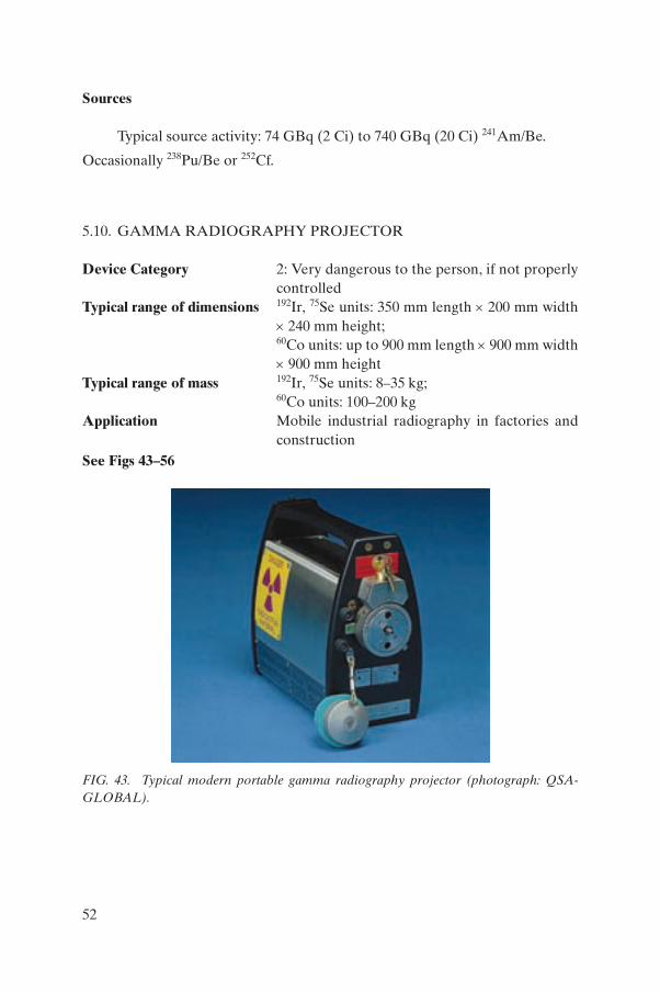
Sources
Typical source activity: 74 GBq (2 Ci) to 740 GBq (20 Ci) 241Am/Be.
Occasionally 238Pu/Be or 252Cf.
5.10. GAMMA RADIOGRAPHY PROJECTOR
Device Category 2: Very dangerous to the person, if not properly controlled
Typical range of dimensions 192Ir, 75Se units: 350 mm length × 200 mm width × 240 mm height;60Co units: up to 900 mm length × 900 mm width × 900 mm height
Typical range of mass 192Ir, 75Se units: 8–35 kg;60Co units: 100–200 kg
Application Mobile industrial radiography in factories and construction
See Figs 43–56
FIG. 43. Typical modern portable gamma radiography projector (photograph: QSA-GLOBAL).
52
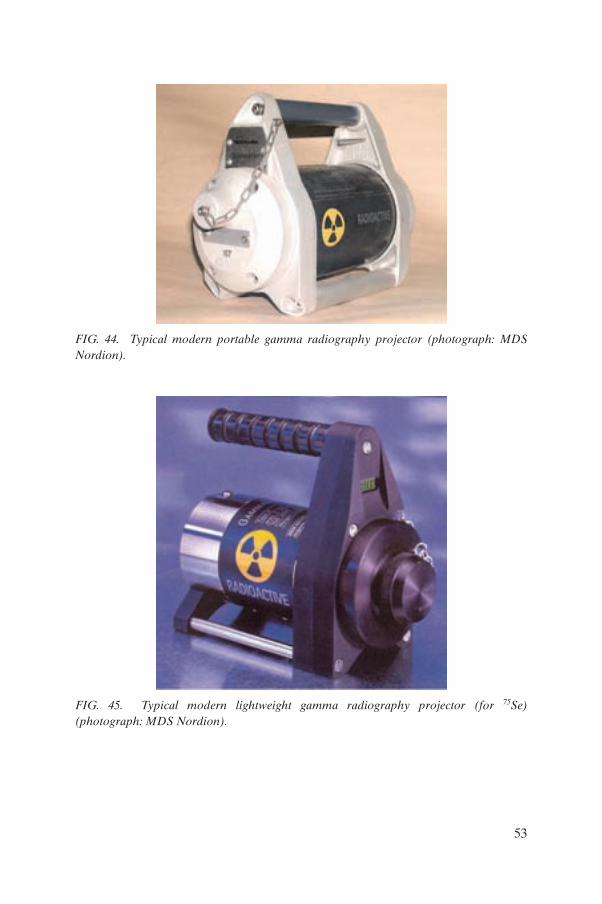
FIG. 44. Typical modern portable gamma radiography projector (photograph: MDS Nordion).
FIG. 45. Typical modern lightweight gamma radiography projector (for 75Se) (photograph: MDS Nordion).
53
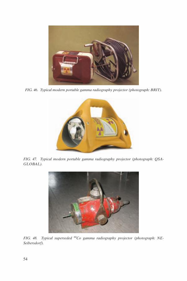
FIG. 46. Typical modern portable gamma radiography projector (photograph: BRIT).
FIG. 47. Typical modern portable gamma radiography projector (photograph: QSA-GLOBAL).
FIG. 48. Typical superseded 60Co gamma radiography projector (photograph: NE- Seibersdorf).
54
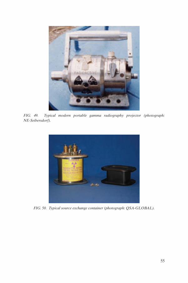
FIG. 49. Typical modern portable gamma radiography projector (photograph: NE-Seibersdorf).
FIG. 50. Typical source exchange container (photograph: QSA-GLOBAL).
55
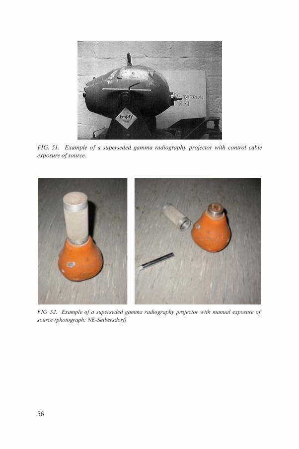
FIG. 51. Example of a superseded gamma radiography projector with control cable exposure of source.
FIG. 52. Example of a superseded gamma radiography projector with manual exposure offsource (photograph: NE-Seibersdorf)
56
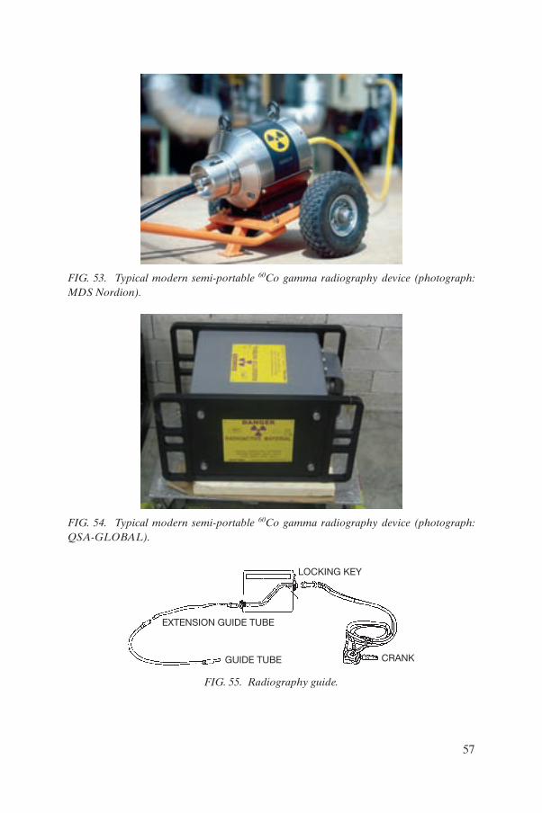
FIG. 53. Typical modern semi-portable 60Co gamma radiography device (photograph: MDS Nordion).
FIG. 54. Typical modern semi-portable 60Co gamma radiography device (photograph: QSA-GLOBAL).
LOCKING KEY
GUIDE TUBE
EXTENSION GUIDE TUBE
CRANK
FIG. 55. Radiography guide.
57
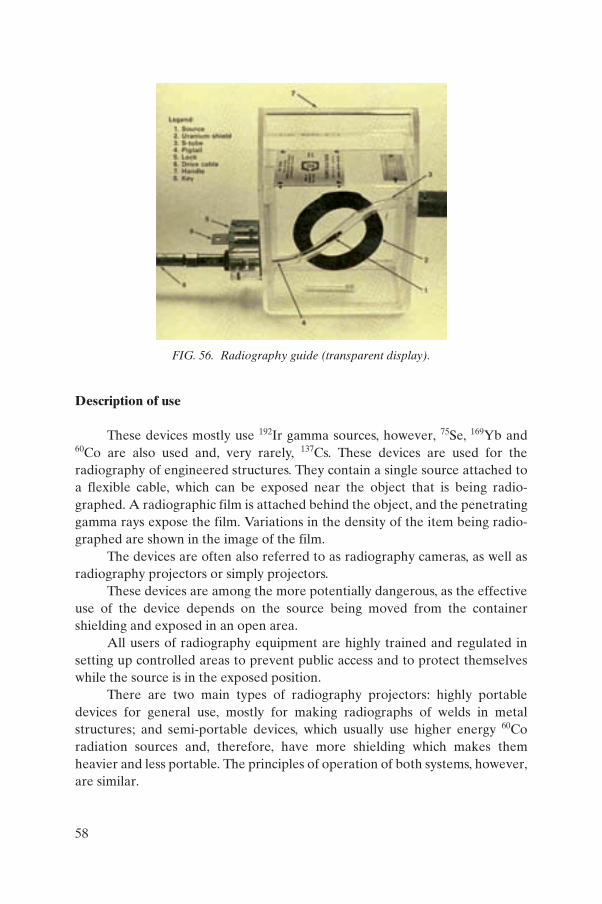
Description of use
These devices mostly use 192Ir gamma sources, however, 75Se, 169Yb and 60Co are also used and, very rarely, 137Cs. These devices are used for the radiography of engineered structures. They contain a single source attached to a flexible cable, which can be exposed near the object that is being radio-graphed. A radiographic film is attached behind the object, and the penetrating gamma rays expose the film. Variations in the density of the item being radio-graphed are shown in the image of the film.
The devices are often also referred to as radiography cameras, as well as radiography projectors or simply projectors.
These devices are among the more potentially dangerous, as the effective use of the device depends on the source being moved from the container shielding and exposed in an open area.
All users of radiography equipment are highly trained and regulated in setting up controlled areas to prevent public access and to protect themselves while the source is in the exposed position.
There are two main types of radiography projectors: highly portable devices for general use, mostly for making radiographs of welds in metal structures; and semi-portable devices, which usually use higher energy 60Co radiation sources and, therefore, have more shielding which makes them heavier and less portable. The principles of operation of both systems, however, are similar.
FIG. 56. Radiography guide (transparent display).
58
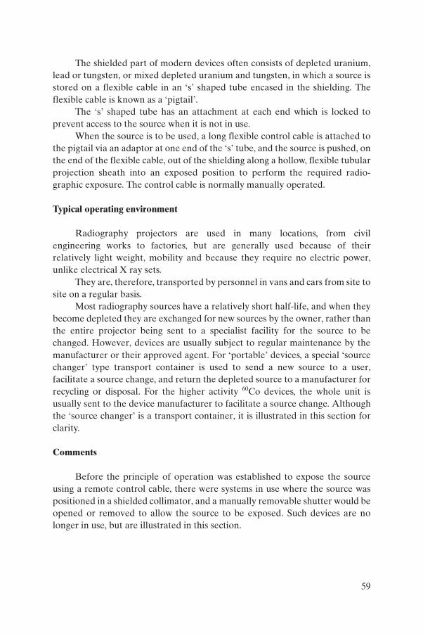
The shielded part of modern devices often consists of depleted uranium, lead or tungsten, or mixed depleted uranium and tungsten, in which a source is stored on a flexible cable in an ‘s’ shaped tube encased in the shielding. The flexible cable is known as a ‘pigtail’.
The ‘s’ shaped tube has an attachment at each end which is locked to prevent access to the source when it is not in use.
When the source is to be used, a long flexible control cable is attached to the pigtail via an adaptor at one end of the ‘s’ tube, and the source is pushed, on the end of the flexible cable, out of the shielding along a hollow, flexible tubular projection sheath into an exposed position to perform the required radio-graphic exposure. The control cable is normally manually operated.
Typical operating environment
Radiography projectors are used in many locations, from civil engineering works to factories, but are generally used because of their relatively light weight, mobility and because they require no electric power, unlike electrical X ray sets.
They are, therefore, transported by personnel in vans and cars from site to site on a regular basis.
Most radiography sources have a relatively short half-life, and when they become depleted they are exchanged for new sources by the owner, rather than the entire projector being sent to a specialist facility for the source to be changed. However, devices are usually subject to regular maintenance by the manufacturer or their approved agent. For ‘portable’ devices, a special ‘source changer’ type transport container is used to send a new source to a user, facilitate a source change, and return the depleted source to a manufacturer for recycling or disposal. For the higher activity 60Co devices, the whole unit is usually sent to the device manufacturer to facilitate a source change. Although the ‘source changer’ is a transport container, it is illustrated in this section for clarity.
Comments
Before the principle of operation was established to expose the source using a remote control cable, there were systems in use where the source was positioned in a shielded collimator, and a manually removable shutter would be opened or removed to allow the source to be exposed. Such devices are no longer in use, but are illustrated in this section.
59
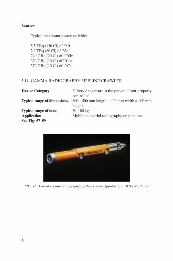
Sources
Typical maximum source activities:
5.5 TBq (150 Ci) of 192Ir;2.9 TBq (80 Ci) of 75Se;740 GBq (20 Ci) of 169Yb;370 GBq (10 Ci) of 60Co;370 GBq (10 Ci) of 137Cs.
5.11. GAMMA RADIOGRAPHY PIPELINE CRAWLER
Device Category 2: Very dangerous to the person, if not properly controlled
Typical range of dimensions 800–1500 mm length × 400 mm width × 400 mm height
Typical range of mass 50–100 kgApplication Mobile industrial radiography on pipelinesSee Figs 57–59
FIG. 57. Typical gamma radiography pipeline crawler (photograph: MDS Nordion).
60
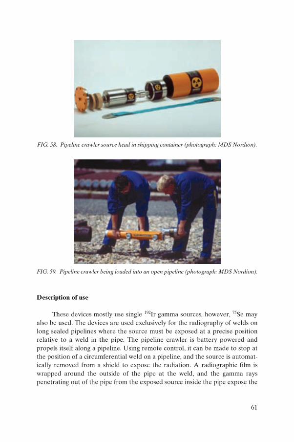
Description of use
These devices mostly use single 192Ir gamma sources, however, 75Se may also be used. The devices are used exclusively for the radiography of welds on long sealed pipelines where the source must be exposed at a precise position relative to a weld in the pipe. The pipeline crawler is battery powered and propels itself along a pipeline. Using remote control, it can be made to stop at the position of a circumferential weld on a pipeline, and the source is automat-ically removed from a shield to expose the radiation. A radiographic film is wrapped around the outside of the pipe at the weld, and the gamma rays penetrating out of the pipe from the exposed source inside the pipe expose the
FIG. 58. Pipeline crawler source head in shipping container (photograph: MDS Nordion).
FIG. 59. Pipeline crawler being loaded into an open pipeline (photograph: MDS Nordion).
61
film. Variations in the density of the item being radiographed are shown in the image of the film.
All users of radiography equipment are highly trained and regulated in setting up controlled areas to prevent public access and to protect themselves while the source is in the exposed position.
Typical operating environment
Pipeline crawlers are used in most applications where the quality of newly laid pipelines, or monitoring of the degradation of old pipelines, is required. This includes process, petrochemical and gas distribution industries.
They are, therefore, transported by personnel in vans and cars from site to site on a regular basis.
The source is held in a shielded head which is transported in a separate container and attached to the pipeline crawler on-site before use.
In most instances, sources are changed only by the supplier or manufac-turer of the pipeline crawler due to the complexity of the operation and the requirement for specialized shielded handling equipment.
Sources
Typical maximum source activities: 5.5 TBq (150 Ci) 192Ir; 2.9 TBq (80 Ci) 75Se.
5.12. HIGH ACTIVITY GAUGES
Device Category 3: Dangerous to the person, if not properly controlled
Typical range of dimensions 200–400 mm diameter × 300–700 mm lengthTypical range of mass 20–400 kgApplication Industrial process controlSee Figs 60–69
62
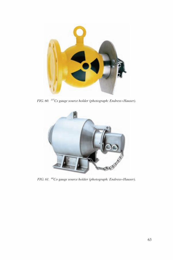
FIG. 60. 137Cs gauge source holder (photograph: Endress+Hauser).
FIG. 61. 60Co gauge source holder (photograph: Endress+Hauser).
63
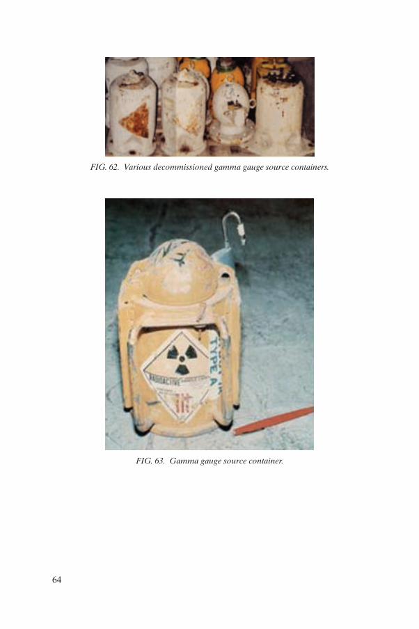
FIG. 62. Various decommissioned gamma gauge source containers.
FIG. 63. Gamma gauge source container.
64
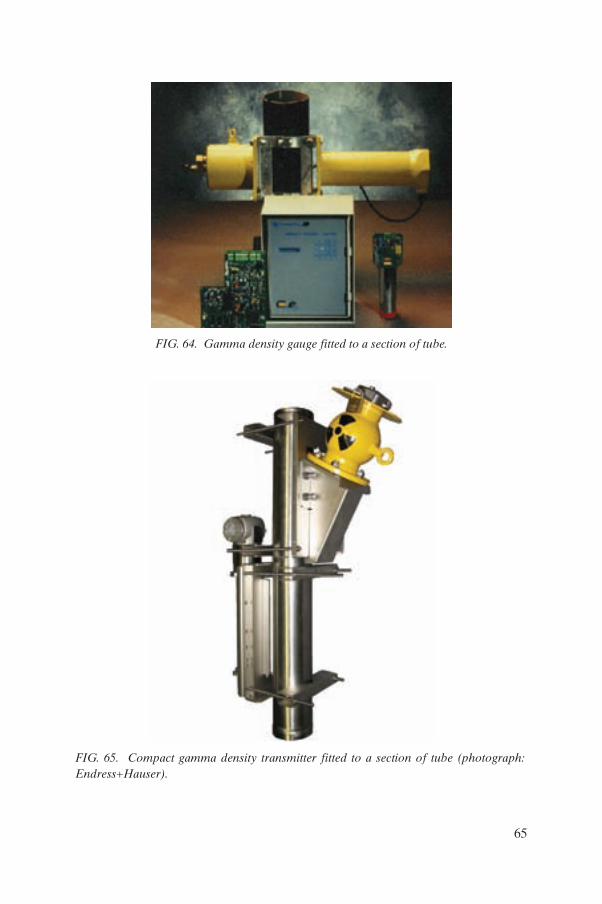
FIG. 64. Gamma density gauge fitted to a section of tube.
FIG. 65. Compact gamma density transmitter fitted to a section of tube (photograph: Endress+Hauser).
65
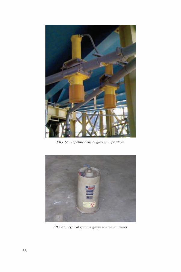
FIG. 66. Pipeline density gauges in position.
FIG. 67. Typical gamma gauge source container.
66
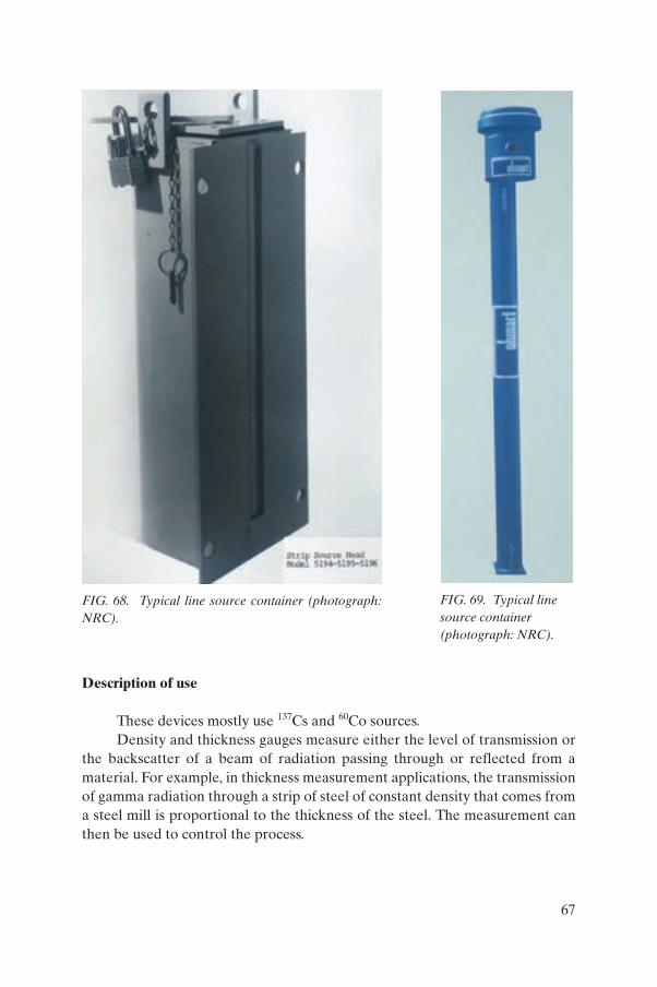
Description of use
These devices mostly use 137Cs and 60Co sources.Density and thickness gauges measure either the level of transmission or
the backscatter of a beam of radiation passing through or reflected from a material. For example, in thickness measurement applications, the transmission of gamma radiation through a strip of steel of constant density that comes from a steel mill is proportional to the thickness of the steel. The measurement can then be used to control the process.
FIG. 68. Typical line source container (photograph: NRC).
FIG. 69. Typical line source container (photograph: NRC).
67
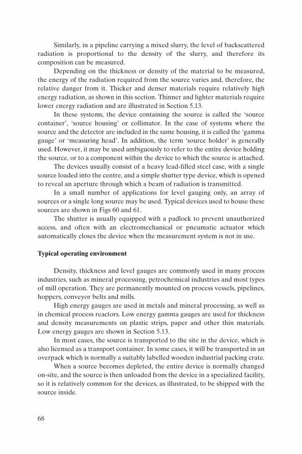
Similarly, in a pipeline carrying a mixed slurry, the level of backscattered radiation is proportional to the density of the slurry, and therefore its composition can be measured.
Depending on the thickness or density of the material to be measured, the energy of the radiation required from the source varies and, therefore, the relative danger from it. Thicker and denser materials require relatively high energy radiation, as shown in this section. Thinner and lighter materials require lower energy radiation and are illustrated in Section 5.13.
In these systems, the device containing the source is called the ‘source container’, ‘source housing’ or collimator. In the case of systems where the source and the detector are included in the same housing, it is called the ‘gamma gauge’ or ‘measuring head’. In addition, the term ‘source holder’ is generally used. However, it may be used ambiguously to refer to the entire device holding the source, or to a component within the device to which the source is attached.
The devices usually consist of a heavy lead-filled steel case, with a single source loaded into the centre, and a simple shutter type device, which is opened to reveal an aperture through which a beam of radiation is transmitted.
In a small number of applications for level gauging only, an array of sources or a single long source may be used. Typical devices used to house these sources are shown in Figs 60 and 61.
The shutter is usually equipped with a padlock to prevent unauthorized access, and often with an electromechanical or pneumatic actuator which automatically closes the device when the measurement system is not in use.
Typical operating environment
Density, thickness and level gauges are commonly used in many process industries, such as mineral processing, petrochemical industries and most types of mill operation. They are permanently mounted on process vessels, pipelines, hoppers, conveyor belts and mills.
High energy gauges are used in metals and mineral processing, as well as in chemical process reactors. Low energy gamma gauges are used for thickness and density measurements on plastic strips, paper and other thin materials. Low energy gauges are shown in Section 5.13.
In most cases, the source is transported to the site in the device, which is also licensed as a transport container. In some cases, it will be transported in an overpack which is normally a suitably labelled wooden industrial packing crate.
When a source becomes depleted, the entire device is normally changed on-site, and the source is then unloaded from the device in a specialized facility, so it is relatively common for the devices, as illustrated, to be shipped with the source inside.
68
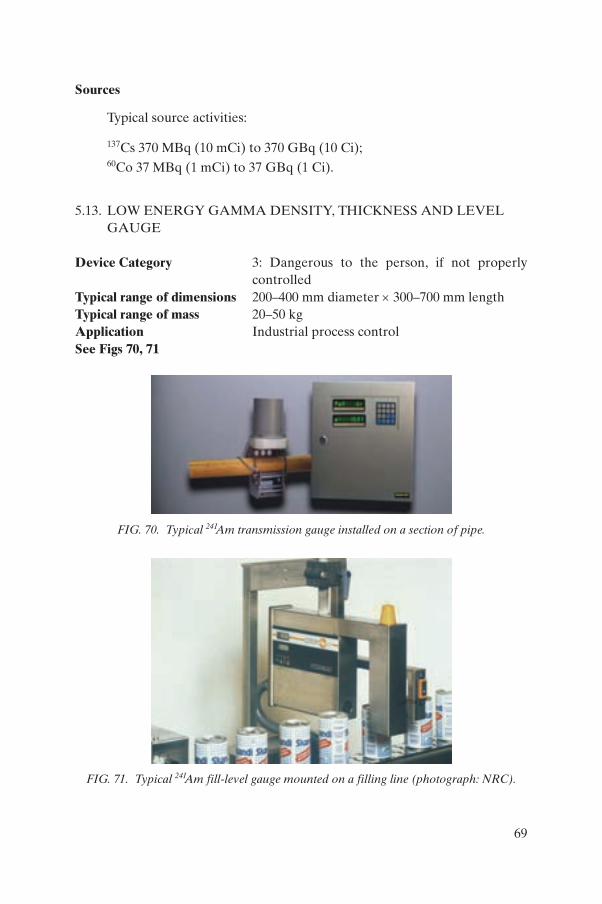
Sources
Typical source activities:
137Cs 370 MBq (10 mCi) to 370 GBq (10 Ci);
60Co 37 MBq (1 mCi) to 37 GBq (1 Ci).
5.13. LOW ENERGY GAMMA DENSITY, THICKNESS AND LEVEL GAUGE
Device Category 3: Dangerous to the person, if not properly controlled
Typical range of dimensions 200–400 mm diameter × 300–700 mm lengthTypical range of mass 20–50 kgApplication Industrial process controlSee Figs 70, 71
FIG. 70. Typical 241Am transmission gauge installed on a section of pipe.
FIG. 71. Typical 241Am fill-level gauge mounted on a filling line (photograph: NRC).
69
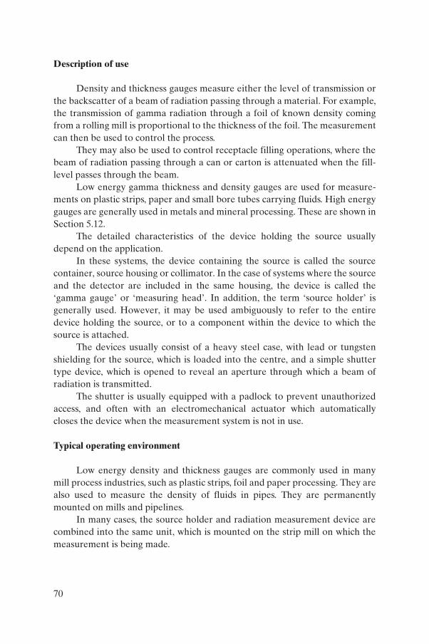
Description of use
Density and thickness gauges measure either the level of transmission or the backscatter of a beam of radiation passing through a material. For example, the transmission of gamma radiation through a foil of known density coming from a rolling mill is proportional to the thickness of the foil. The measurement can then be used to control the process.
They may also be used to control receptacle filling operations, where the beam of radiation passing through a can or carton is attenuated when the fill-level passes through the beam.
Low energy gamma thickness and density gauges are used for measure-ments on plastic strips, paper and small bore tubes carrying fluids. High energy gauges are generally used in metals and mineral processing. These are shown in Section 5.12.
The detailed characteristics of the device holding the source usually depend on the application.
In these systems, the device containing the source is called the source container, source housing or collimator. In the case of systems where the source and the detector are included in the same housing, the device is called the ‘gamma gauge’ or ‘measuring head’. In addition, the term ‘source holder’ is generally used. However, it may be used ambiguously to refer to the entire device holding the source, or to a component within the device to which the source is attached.
The devices usually consist of a heavy steel case, with lead or tungsten shielding for the source, which is loaded into the centre, and a simple shutter type device, which is opened to reveal an aperture through which a beam of radiation is transmitted.
The shutter is usually equipped with a padlock to prevent unauthorized access, and often with an electromechanical actuator which automatically closes the device when the measurement system is not in use.
Typical operating environment
Low energy density and thickness gauges are commonly used in many mill process industries, such as plastic strips, foil and paper processing. They are also used to measure the density of fluids in pipes. They are permanently mounted on mills and pipelines.
In many cases, the source holder and radiation measurement device are combined into the same unit, which is mounted on the strip mill on which the measurement is being made.
70
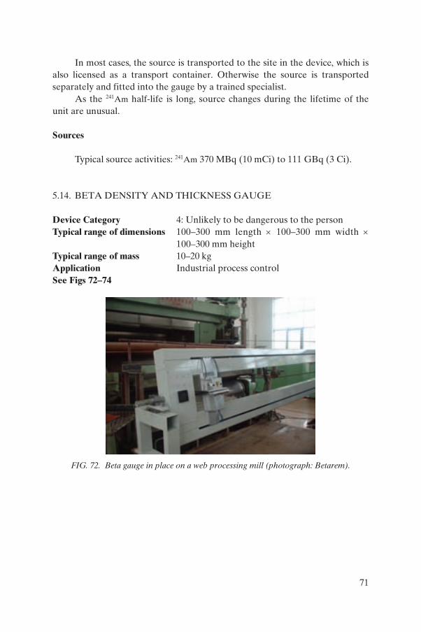
In most cases, the source is transported to the site in the device, which is also licensed as a transport container. Otherwise the source is transported separately and fitted into the gauge by a trained specialist.
As the 241Am half-life is long, source changes during the lifetime of the unit are unusual.
Sources
Typical source activities: 241Am 370 MBq (10 mCi) to 111 GBq (3 Ci).
5.14. BETA DENSITY AND THICKNESS GAUGE
Device Category 4: Unlikely to be dangerous to the personTypical range of dimensions 100–300 mm length × 100–300 mm width ×
100–300 mm heightTypical range of mass 10–20 kgApplication Industrial process controlSee Figs 72–74
FIG. 72. Beta gauge in place on a web processing mill (photograph: Betarem).
71
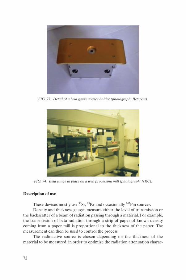
Description of use
These devices mostly use 90Sr, 85Kr and occasionally 147Pm sources.Density and thickness gauges measure either the level of transmission or
the backscatter of a beam of radiation passing through a material. For example, the transmission of beta radiation through a strip of paper of known density coming from a paper mill is proportional to the thickness of the paper. The measurement can then be used to control the process.
The radioactive source is chosen depending on the thickness of the material to be measured, in order to optimize the radiation attenuation charac-
FIG. 73. Detail of a beta gauge source holder (photograph: Betarem).
FIG. 74. Beta gauge in place on a web processing mill (photograph: NRC).
72
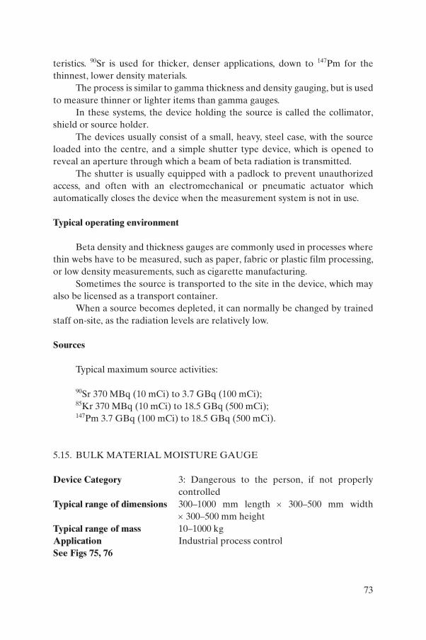
teristics. 90Sr is used for thicker, denser applications, down to 147Pm for the thinnest, lower density materials.
The process is similar to gamma thickness and density gauging, but is used to measure thinner or lighter items than gamma gauges.
In these systems, the device holding the source is called the collimator, shield or source holder.
The devices usually consist of a small, heavy, steel case, with the source loaded into the centre, and a simple shutter type device, which is opened to reveal an aperture through which a beam of beta radiation is transmitted.
The shutter is usually equipped with a padlock to prevent unauthorized access, and often with an electromechanical or pneumatic actuator which automatically closes the device when the measurement system is not in use.
Typical operating environment
Beta density and thickness gauges are commonly used in processes where thin webs have to be measured, such as paper, fabric or plastic film processing, or low density measurements, such as cigarette manufacturing.
Sometimes the source is transported to the site in the device, which may also be licensed as a transport container.
When a source becomes depleted, it can normally be changed by trained staff on-site, as the radiation levels are relatively low.
Sources
Typical maximum source activities:
90Sr 370 MBq (10 mCi) to 3.7 GBq (100 mCi);85Kr 370 MBq (10 mCi) to 18.5 GBq (500 mCi);147Pm 3.7 GBq (100 mCi) to 18.5 GBq (500 mCi).
5.15. BULK MATERIAL MOISTURE GAUGE
Device Category 3: Dangerous to the person, if not properly controlled
Typical range of dimensions 300–1000 mm length × 300–500 mm width × 300–500 mm height
Typical range of mass 10–1000 kgApplication Industrial process controlSee Figs 75, 76
73
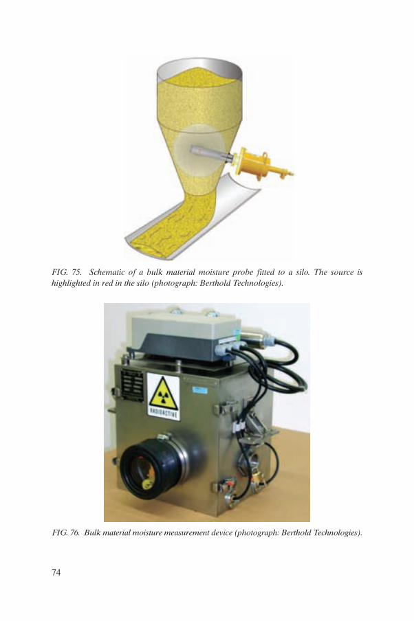
FIG. 75. Schematic of a bulk material moisture probe fitted to a silo. The source is highlighted in red in the silo (photograph: Berthold Technologies).
FIG. 76. Bulk material moisture measurement device (photograph: Berthold Technologies).
74
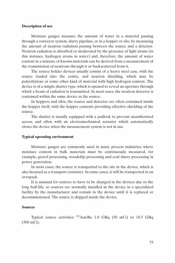
Description of use
Moisture gauges measure the amount of water in a material passing through a conveyor system, slurry pipeline, or in a hopper or silo, by measuring the amount of neutron radiation passing between the source and a detector. Neutron radiation is absorbed or moderated by the presence of light atoms (in this instance, hydrogen atoms in water) and, therefore, the amount of water content in a mixture of known materials can be derived from a measurement of the transmission of neutrons through it or backscattered from it.
The source holder devices usually consist of a heavy steel case, with the source loaded into the centre, and neutron shielding, which may be polyethylene or some other kind of material with high hydrogen content. The device is of a simple shutter type, which is opened to reveal an aperture through which a beam of radiation is transmitted. In most cases, the neutron detector is contained within the same device as the source.
In hoppers and silos, the source and detector are often contained inside the hopper itself, with the hopper contents providing effective shielding of the source.
The shutter is usually equipped with a padlock to prevent unauthorized access, and often with an electromechanical actuator which automatically closes the device when the measurement system is not in use.
Typical operating environment
Moisture gauges are commonly used in many process industries where moisture content in bulk materials must be continuously measured, for example, gravel processing, woodchip processing and coal slurry processing in power generation.
In most cases, the source is transported to the site in the device, which is also licensed as a transport container. In some cases, it will be transported in an overpack.
It is unusual for sources to have to be changed in the devices due to the long half-life, so sources are normally installed in the device in a specialized facility by the manufacturer and remain in the device until it is replaced or decommissioned. The source is shipped inside the device.
Sources
Typical source activities: 241Am/Be 1.8 GBq (50 mCi) to 18.5 GBq (500 mCi).
75
5.16. SOIL MOISTURE/DENSITY GAUGE
Device Category 4: Unlikely to be dangerous to the personTypical range of dimensions Device: 200 mm length × 300 mm width ×
1000 mm height (with handle in operating position);Carrying case: 800 mm length × 400 mm width ×300 mm height
Typical range of mass Device: 30 kg Device in carrying case: 40 kg
Application Civil engineering, road building and agricultureSee Figs 77, 78
FIG. 77. Typical soil moisture and density gauge, shown with a carrying case (photograph: Troxler Labs).
FIG. 78. Typical soil moisture and density gauge, shown with a carrying case (photograph: CPN International).
76
Description of use
These devices use two types of radiation sources together: a 137Cs high energy gamma source of approximately 40 MBq (1 mCi) and an 241Am/Be neutron source of approximately 2 GBq (55 mCi).
The devices are portable and are normally used to measure the density and moisture content of soil and building materials. The density is determined by measuring the amount of backscattered radiation from the gamma source, and the moisture content is derived from the gamma measurement and a measurement of the amount of backscattered neutron radiation.
The sources are contained in a shielded unit in the device, which is usually made of lead and polythene. They are exposed in use by opening a shutter which allows collimated beams of radiation to be directed into the ground. The shutter is locked when the device is not in use.
Typical operating environment
The devices are in common use in the construction and agricultural industries in many countries. They are portable and normally transported in protective carrying cases.
The sources are usually retained inside their shielding with some kind of tamper proof screws or a permanent fixing, and the sources are not normally exchanged during the working life of the device.
Due to the manner in which they are used on construction sites and agricultural land, these devices have a relatively high probability of being lost or mislaid. However, the hazard level is very low because the activity of the sources is low and they are well protected in the units.
Sources
Typical maximum source activities:
137Cs 370 MBq (10 mCi);241Am/Be 1.9 GBq (50 mCi).
77
5.17. X RAY FLUORESCENCE ANALYSER
Device Category 5: Most unlikely to be dangerous to the personTypical range of dimensions Hand-held: 200 mm length × 100 mm width ×
100 mm height;Laboratory and process control: 500 mm length × 500 mm width × 1500 mm height
Typical range of mass Hand-held: 1–2 kg Laboratory and process control: 20–100 kg
Application Industrial analysisSee Figs 79–82
FIG. 79. Typical hand-held X ray analysis device (photograph: Spectro).
FIG. 80. Typical hand-held X ray analysis devices (photograph: Thermo).
78
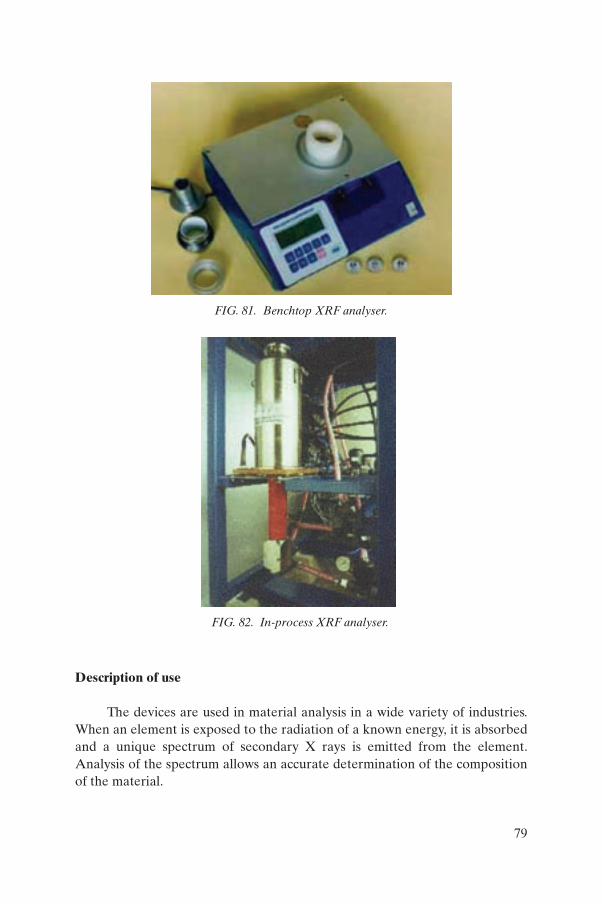
Description of use
The devices are used in material analysis in a wide variety of industries. When an element is exposed to the radiation of a known energy, it is absorbed and a unique spectrum of secondary X rays is emitted from the element. Analysis of the spectrum allows an accurate determination of the composition of the material.
FIG. 81. Benchtop XRF analyser.
FIG. 82. In-process XRF analyser.
79
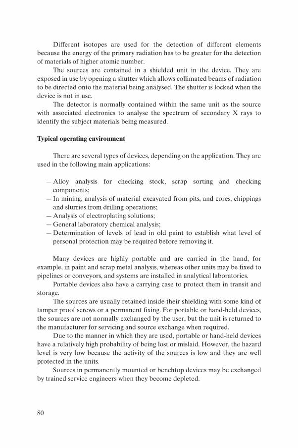
Different isotopes are used for the detection of different elements because the energy of the primary radiation has to be greater for the detection of materials of higher atomic number.
The sources are contained in a shielded unit in the device. They are exposed in use by opening a shutter which allows collimated beams of radiation to be directed onto the material being analysed. The shutter is locked when the device is not in use.
The detector is normally contained within the same unit as the source with associated electronics to analyse the spectrum of secondary X rays to identify the subject materials being measured.
Typical operating environment
There are several types of devices, depending on the application. They are used in the following main applications:
— Alloy analysis for checking stock, scrap sorting and checking components;
— In mining, analysis of material excavated from pits, and cores, chippings and slurries from drilling operations;
— Analysis of electroplating solutions;— General laboratory chemical analysis;— Determination of levels of lead in old paint to establish what level of
personal protection may be required before removing it.
Many devices are highly portable and are carried in the hand, for example, in paint and scrap metal analysis, whereas other units may be fixed to pipelines or conveyors, and systems are installed in analytical laboratories.
Portable devices also have a carrying case to protect them in transit and storage.
The sources are usually retained inside their shielding with some kind of tamper proof screws or a permanent fixing. For portable or hand-held devices, the sources are not normally exchanged by the user, but the unit is returned to the manufacturer for servicing and source exchange when required.
Due to the manner in which they are used, portable or hand-held devices have a relatively high probability of being lost or mislaid. However, the hazard level is very low because the activity of the sources is low and they are well protected in the units.
Sources in permanently mounted or benchtop devices may be exchanged by trained service engineers when they become depleted.
80
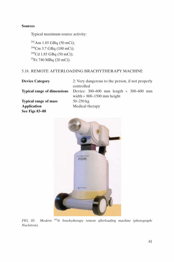
Sources
Typical maximum source activity:
241Am 1.85 GBq (50 mCi);
244Cm 3.7 GBq (100 mCi);
109Cd 1.85 GBq (50 mCi);
55Fe 740 MBq (20 mCi).
5.18. REMOTE AFTERLOADING BRACHYTHERAPY MACHINE
Device Category 2: Very dangerous to the person, if not properly controlled
Typical range of dimensions Device: 300–600 mm length × 300–600 mm width × 800–1500 mm height
Typical range of mass 50–250 kgApplication Medical therapySee Figs 83–88
FIG. 83. Modern 192Ir brachytherapy remote afterloading machine (photograph: Nucletron).
81
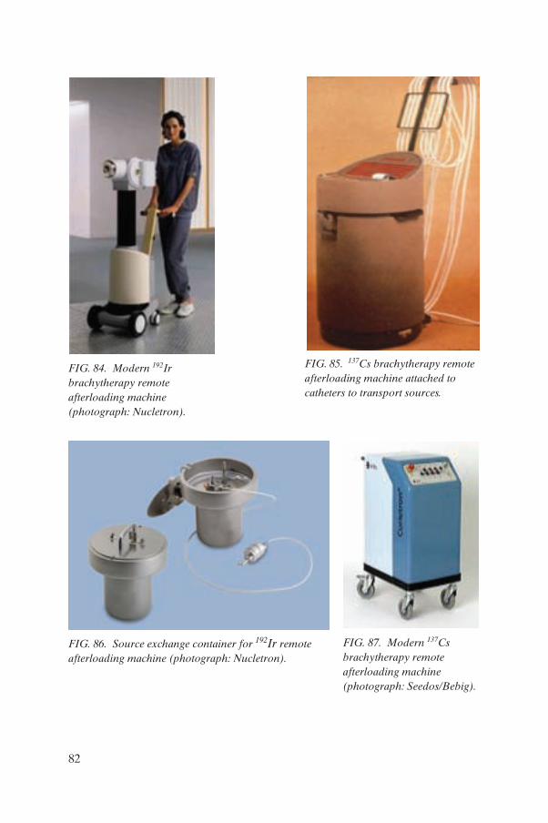
FIG. 84. Modern 192Ir brachytherapy remote afterloading machine (photograph: Nucletron).
FIG. 85. 137Cs brachytherapy remote afterloading machine attached to catheters to transport sources.
FIG. 86. Source exchange container for 192Ir remote afterloading machine (photograph: Nucletron).
FIG. 87. Modern 137Cs brachytherapy remote afterloading machine (photograph: Seedos/Bebig).
82
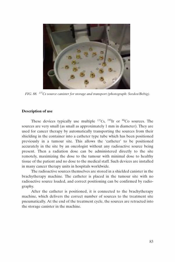
Description of use
These devices typically use multiple 137Cs, 192Ir or 60Co sources. The sources are very small (as small as approximately 1 mm in diameter). They are used for cancer therapy by automatically transporting the sources from their shielding in the container into a catheter type tube which has been positioned previously in a tumour site. This allows the ‘catheter’ to be positioned accurately in the site by an oncologist without any radioactive source being present. Then a radiation dose can be administered directly to the site remotely, maximizing the dose to the tumour with minimal dose to healthy tissue of the patient and no dose to the medical staff. Such devices are installed in many cancer therapy units in hospitals worldwide.
The radioactive sources themselves are stored in a shielded canister in the brachytherapy machine. The catheter is placed in the tumour site with no radioactive source loaded, and correct positioning can be confirmed by radio-graphy.
After the catheter is positioned, it is connected to the brachytherapy machine, which delivers the correct number of sources to the treatment site pneumatically. At the end of the treatment cycle, the sources are retracted into the storage canister in the machine.
FIG. 88. 137Cs source canister for storage and transport (photograph: Seedos/Bebig).
83
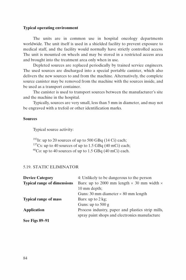
Typical operating environment
The units are in common use in hospital oncology departments worldwide. The unit itself is used in a shielded facility to prevent exposure to medical staff, and the facility would normally have strictly controlled access. The unit is mounted on wheels and may be stored in a restricted access area and brought into the treatment area only when in use.
Depleted sources are replaced periodically by trained service engineers. The used sources are discharged into a special portable canister, which also delivers the new sources to and from the machine. Alternatively, the complete source canister may be removed from the machine with the sources inside, and be used as a transport container.
The canister is used to transport sources between the manufacturer’s site and the machine in the hospital.
Typically, sources are very small, less than 5 mm in diameter, and may not be engraved with a trefoil or other identification marks.
Sources
Typical source activity:
192Ir: up to 20 sources of up to 500 GBq (14 Ci) each;137Cs: up to 40 sources of up to 1.5 GBq (40 mCi) each;60Co: up to 40 sources of up to 1.5 GBq (40 mCi) each.
5.19. STATIC ELIMINATOR
Device Category 4: Unlikely to be dangerous to the personTypical range of dimensions Bars: up to 2000 mm length × 30 mm width ×
10 mm depth;Guns: 30 mm diameter × 80 mm length
Typical range of mass Bars: up to 2 kg; Guns: up to 500 g
Application Process industry, paper and plastics strip mills, spray paint shops and electronics manufacture
See Figs 89–91
84
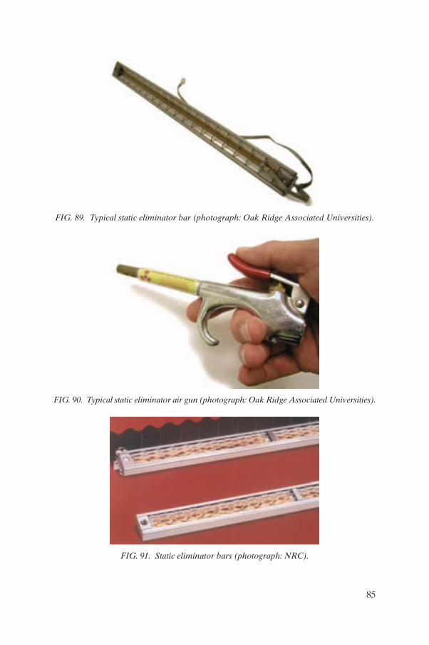
FIG. 89. Typical static eliminator bar (photograph: Oak Ridge Associated Universities).
FIG. 90. Typical static eliminator air gun (photograph: Oak Ridge Associated Universities).
FIG. 91. Static eliminator bars (photograph: NRC).
85
Description of use
These types of device use a precious metal rolled foil with 210Po incorpo-rated into it with a thin layer of pure precious metal sealing the 210Po composite into the foil.
There are two main types of device: bars and guns. Bar devices emit a ‘cloud’ of alpha particles to a distance of about 2 in. (8 cm) from the surface which ionize the surrounding gas (air) and allow any static charges on surrounding materials to be safely conducted to ground by slow discharge. Gun devices are used on pneumatic air lines, and the air passing through is ionized. The resulting stream of air can be used for blowing dust from objects and eliminating static charge on them which attracts dust.
For bars, the foil is contained in a metal casing with a grille to allow free movement of ionized air, but protection to the foil; and for guns, the foil is contained within a tubular metal case which forms part of the air line and gun grip.
Typical operating environment
Bars used to be in quite common use in the mill processing of any web where static charge buildup was a problem or fire hazard. Guns were used in clean room applications, such as electronics manufacturing and high quality paint shops.
In the last ten years, their prevalence has reduced significantly due to improvements in electrically powered static eliminators.
Bars are normally mounted across the span of mills, close to the run of the web where the static charge builds up. Guns are used in clean rooms and paint workshops and should be locked away when not in use.
The half-life of 210Po is relatively short (20 weeks), therefore, devices are usually replaced annually on a service contract with their original supplier.
The devices are packaged for transport in normal industrial packaging, such as rigid cardboard or rigid plastic packaging.
Sources
Bars: 210Po up to 2 GBq (55 mCi) when new;Guns: 210Po up to 370 MBq (10 mCi) when new.
86
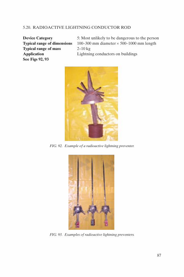
5.20. RADIOACTIVE LIGHTNING CONDUCTOR ROD
Device Category 5: Most unlikely to be dangerous to the personTypical range of dimensions 100–300 mm diameter × 500–1000 mm lengthTypical range of mass 2–10 kgApplication Lightning conductors on buildingsSee Figs 92, 93
FIG. 92. Example of a radioactive lightning preventer.
FIG. 93. Examples of radioactive lightning preventers.
87
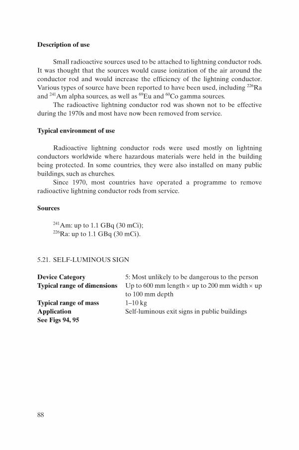
Description of use
Small radioactive sources used to be attached to lightning conductor rods. It was thought that the sources would cause ionization of the air around the conductor rod and would increase the efficiency of the lightning conductor. Various types of source have been reported to have been used, including 226Ra and 241Am alpha sources, as well as 69Eu and 60Co gamma sources.
The radioactive lightning conductor rod was shown not to be effective during the 1970s and most have now been removed from service.
Typical environment of use
Radioactive lightning conductor rods were used mostly on lightning conductors worldwide where hazardous materials were held in the building being protected. In some countries, they were also installed on many public buildings, such as churches.
Since 1970, most countries have operated a programme to remove radioactive lightning conductor rods from service.
Sources
241Am: up to 1.1 GBq (30 mCi);226Ra: up to 1.1 GBq (30 mCi).
5.21. SELF-LUMINOUS SIGN
Device Category 5: Most unlikely to be dangerous to the personTypical range of dimensions Up to 600 mm length × up to 200 mm width × up
to 100 mm depthTypical range of mass 1–10 kgApplication Self-luminous exit signs in public buildingsSee Figs 94, 95
88
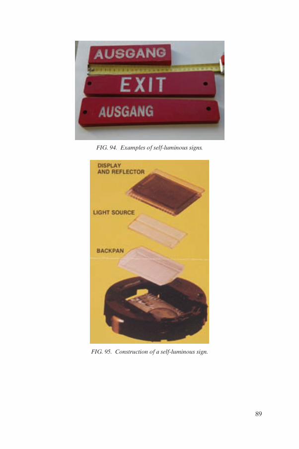
FIG. 94. Examples of self-luminous signs.
FIG. 95. Construction of a self-luminous sign.
89
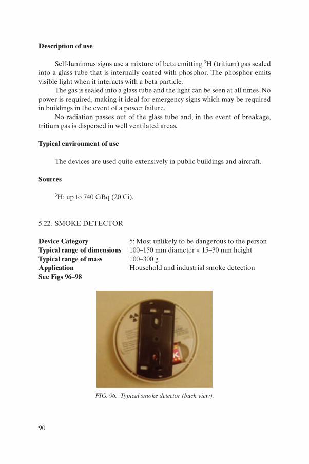
Description of use
Self-luminous signs use a mixture of beta emitting 3H (tritium) gas sealed into a glass tube that is internally coated with phosphor. The phosphor emits visible light when it interacts with a beta particle.
The gas is sealed into a glass tube and the light can be seen at all times. No power is required, making it ideal for emergency signs which may be required in buildings in the event of a power failure.
No radiation passes out of the glass tube and, in the event of breakage, tritium gas is dispersed in well ventilated areas.
Typical environment of use
The devices are used quite extensively in public buildings and aircraft.
Sources
3H: up to 740 GBq (20 Ci).
5.22. SMOKE DETECTOR
Device Category 5: Most unlikely to be dangerous to the personTypical range of dimensions 100–150 mm diameter × 15–30 mm heightTypical range of mass 100–300 gApplication Household and industrial smoke detectionSee Figs 96–98
FIG. 96. Typical smoke detector (back view).
90
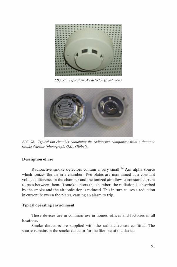
Description of use
Radioactive smoke detectors contain a very small 241Am alpha source which ionizes the air in a chamber. Two plates are maintained at a constant voltage difference in the chamber and the ionized air allows a constant current to pass between them. If smoke enters the chamber, the radiation is absorbed by the smoke and the air ionization is reduced. This in turn causes a reduction in current between the plates, causing an alarm to trip.
Typical operating environment
These devices are in common use in homes, offices and factories in all locations.
Smoke detectors are supplied with the radioactive source fitted. The source remains in the smoke detector for the lifetime of the device.
FIG. 97. Typical smoke detector (front view).
FIG. 98. Typical ion chamber containing the radioactive component from a domestic smoke detector (photograph: QSA-Global).
91
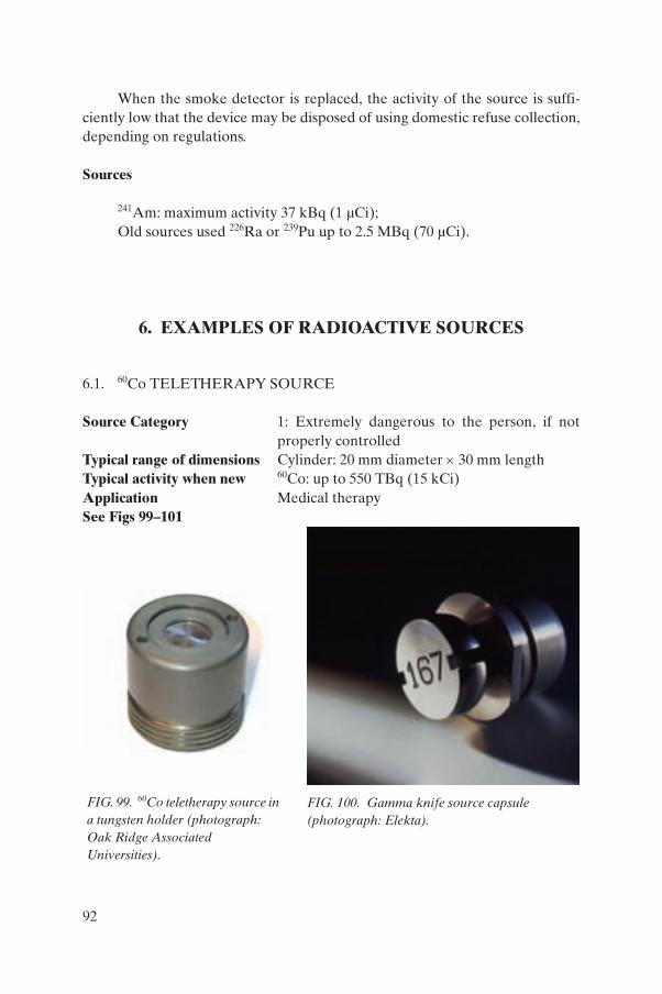
When the smoke detector is replaced, the activity of the source is suffi-ciently low that the device may be disposed of using domestic refuse collection, depending on regulations.
Sources
241Am: maximum activity 37 kBq (1 µCi);Old sources used 226Ra or 239Pu up to 2.5 MBq (70 µCi).
6. EXAMPLES OF RADIOACTIVE SOURCES
6.1. 60Co TELETHERAPY SOURCE
Source Category 1: Extremely dangerous to the person, if not properly controlled
Typical range of dimensions Cylinder: 20 mm diameter × 30 mm length Typical activity when new 60Co: up to 550 TBq (15 kCi) Application Medical therapySee Figs 99–101
FIG. 100. Gamma knife source capsule (photograph: Elekta).
FIG. 99. 60Co teletherapy source in a tungsten holder (photograph: Oak Ridge Associated Universities).
92
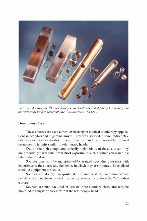
Description of use
These sources are used almost exclusively in medical teletherapy applica-tions in hospitals and in gamma knives. They are also used in some radiometric laboratories for calibration measurements, and are normally housed permanently in units similar to teletherapy heads.
Due to the high energy and typically high activity of these sources, they are potentially hazardous. Even short exposure to such a source can result in a fatal radiation dose.
Sources may only be manipulated by trained specialist operators with experience of the source and the device in which they are mounted. Specialized shielded equipment is needed.
Sources are doubly encapsulated in stainless steel, containing cobalt pellets which have been treated in a nuclear reactor to produce the 60Co radio-isotope.
Sources are manufactured in two or three standard sizes, and may be mounted in tungsten spacers within the teletherapy head.
FIG. 101. A variety of 60Co teletherapy sources with associated fittings for loading into the teletherapy head (photograph: REVISS Services (UK) Ltd).
93
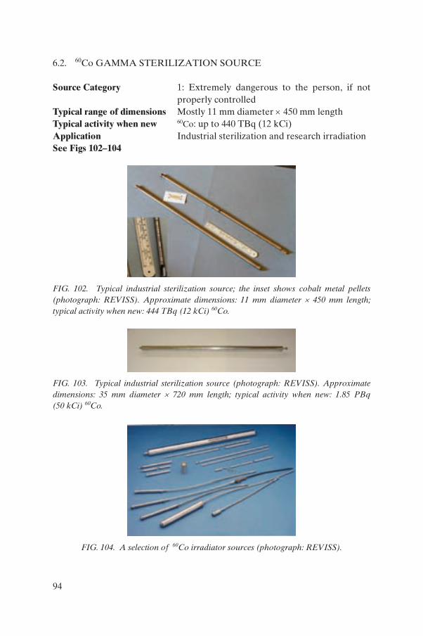
6.2. 60Co GAMMA STERILIZATION SOURCE
Source Category 1: Extremely dangerous to the person, if not properly controlled
Typical range of dimensions Mostly 11 mm diameter × 450 mm lengthTypical activity when new 60Co: up to 440 TBq (12 kCi) Application Industrial sterilization and research irradiationSee Figs 102–104
FIG. 102. Typical industrial sterilization source; the inset shows cobalt metal pellets (photograph: REVISS). Approximate dimensions: 11 mm diameter × 450 mm length; typical activity when new: 444 TBq (12 kCi) 60Co.
FIG. 103. Typical industrial sterilization source (photograph: REVISS). Approximate dimensions: 35 mm diameter × 720 mm length; typical activity when new: 1.85 PBq (50 kCi) 60Co.
FIG. 104. A selection of 60Co irradiator sources (photograph: REVISS).
94
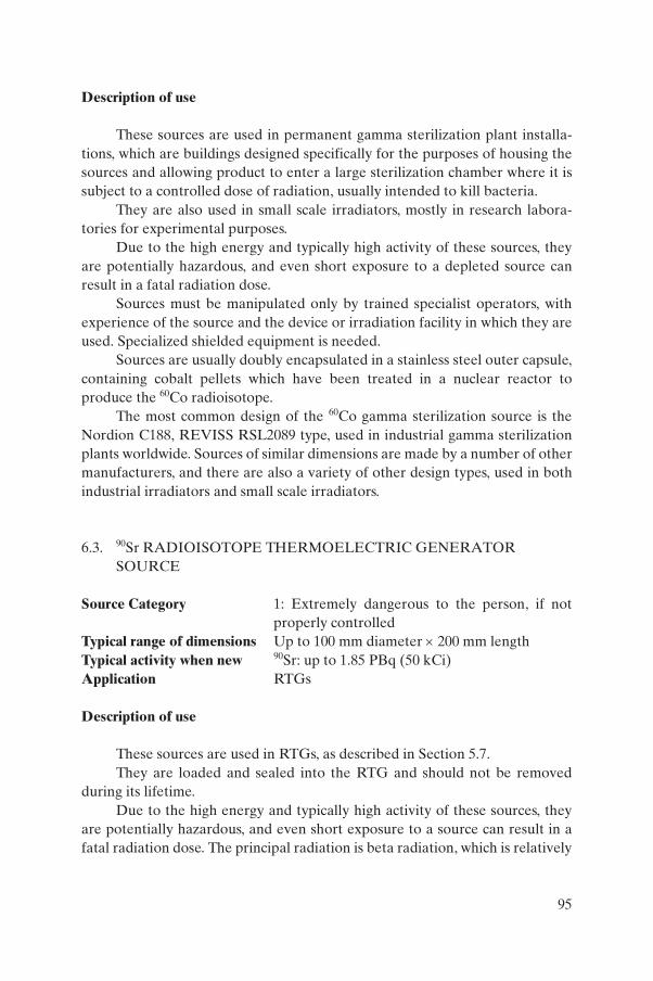
Description of use
These sources are used in permanent gamma sterilization plant installa-tions, which are buildings designed specifically for the purposes of housing the sources and allowing product to enter a large sterilization chamber where it is subject to a controlled dose of radiation, usually intended to kill bacteria.
They are also used in small scale irradiators, mostly in research labora-tories for experimental purposes.
Due to the high energy and typically high activity of these sources, they are potentially hazardous, and even short exposure to a depleted source can result in a fatal radiation dose.
Sources must be manipulated only by trained specialist operators, with experience of the source and the device or irradiation facility in which they are used. Specialized shielded equipment is needed.
Sources are usually doubly encapsulated in a stainless steel outer capsule, containing cobalt pellets which have been treated in a nuclear reactor to produce the 60Co radioisotope.
The most common design of the 60Co gamma sterilization source is the Nordion C188, REVISS RSL2089 type, used in industrial gamma sterilization plants worldwide. Sources of similar dimensions are made by a number of other manufacturers, and there are also a variety of other design types, used in both industrial irradiators and small scale irradiators.
6.3. 90Sr RADIOISOTOPE THERMOELECTRIC GENERATOR SOURCE
Source Category 1: Extremely dangerous to the person, if not properly controlled
Typical range of dimensions Up to 100 mm diameter × 200 mm length Typical activity when new 90Sr: up to 1.85 PBq (50 kCi) Application RTGs
Description of use
These sources are used in RTGs, as described in Section 5.7.They are loaded and sealed into the RTG and should not be removed
during its lifetime.Due to the high energy and typically high activity of these sources, they
are potentially hazardous, and even short exposure to a source can result in a fatal radiation dose. The principal radiation is beta radiation, which is relatively
95
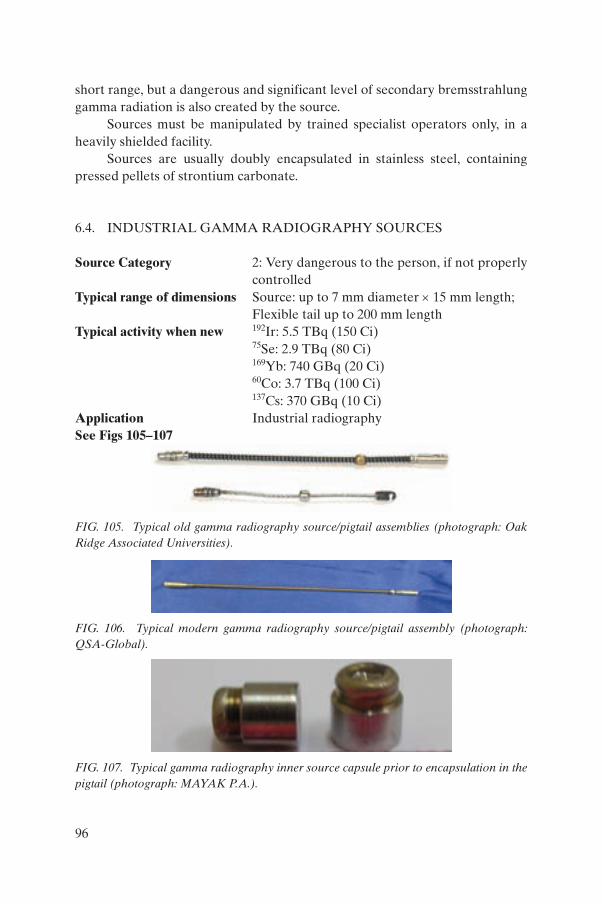
short range, but a dangerous and significant level of secondary bremsstrahlung gamma radiation is also created by the source.
Sources must be manipulated by trained specialist operators only, in a heavily shielded facility.
Sources are usually doubly encapsulated in stainless steel, containing pressed pellets of strontium carbonate.
6.4. INDUSTRIAL GAMMA RADIOGRAPHY SOURCES
Source Category 2: Very dangerous to the person, if not properly controlled
Typical range of dimensions Source: up to 7 mm diameter × 15 mm length; Flexible tail up to 200 mm length
Typical activity when new 192Ir: 5.5 TBq (150 Ci) 75Se: 2.9 TBq (80 Ci) 169Yb: 740 GBq (20 Ci) 60Co: 3.7 TBq (100 Ci) 137Cs: 370 GBq (10 Ci)
Application Industrial radiographySee Figs 105–107
FIG. 105. Typical old gamma radiography source/pigtail assemblies (photograph: Oak Ridge Associated Universities).
FIG. 106. Typical modern gamma radiography source/pigtail assembly (photograph: QSA-Global).
FIG. 107. Typical gamma radiography inner source capsule prior to encapsulation in the pigtail (photograph: MAYAK P.A.).
96
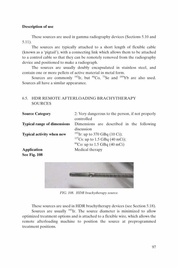
Description of use
These sources are used in gamma radiography devices (Sections 5.10 and 5.11).
The sources are typically attached to a short length of flexible cable (known as a ‘pigtail’), with a connecting link which allows them to be attached to a control cable so that they can be remotely removed from the radiography device and positioned to make a radiograph.
The sources are usually doubly encapsulated in stainless steel, and contain one or more pellets of active material in metal form.
Sources are commonly 192Ir, but 60Co, 75Se and 169Yb are also used. Sources all have a similar appearance.
6.5. HDR REMOTE AFTERLOADING BRACHYTHERAPY SOURCES
Source Category 2: Very dangerous to the person, if not properly controlled
Typical range of dimensions Dimensions are described in the following discussion
Typical activity when new 192Ir: up to 370 GBq (10 Ci); 137Cs: up to 1.5 GBq (40 mCi); 60Co: up to 1.5 GBq (40 mCi)
Application Medical therapySee Fig. 108
These sources are used in HDR brachytherapy devices (see Section 5.18).Sources are usually 192Ir. The source diameter is minimized to allow
optimized treatment options and is attached to a flexible wire, which allows the remote afterloading machine to position the source at preprogrammed treatment positions.
FIG. 108. HDR brachytherapy source.
97
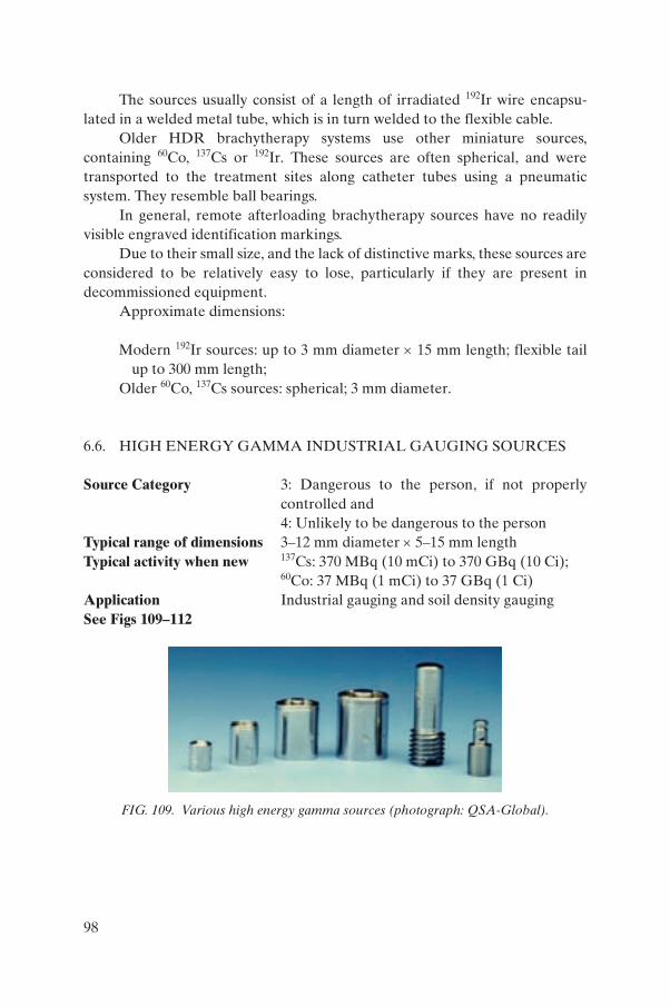
The sources usually consist of a length of irradiated 192Ir wire encapsu-lated in a welded metal tube, which is in turn welded to the flexible cable.
Older HDR brachytherapy systems use other miniature sources, containing 60Co, 137Cs or 192Ir. These sources are often spherical, and were transported to the treatment sites along catheter tubes using a pneumatic system. They resemble ball bearings.
In general, remote afterloading brachytherapy sources have no readily visible engraved identification markings.
Due to their small size, and the lack of distinctive marks, these sources are considered to be relatively easy to lose, particularly if they are present in decommissioned equipment.
Approximate dimensions:
Modern 192Ir sources: up to 3 mm diameter × 15 mm length; flexible tail up to 300 mm length;
Older 60Co, 137Cs sources: spherical; 3 mm diameter.
6.6. HIGH ENERGY GAMMA INDUSTRIAL GAUGING SOURCES
Source Category 3: Dangerous to the person, if not properly controlled and 4: Unlikely to be dangerous to the person
Typical range of dimensions 3–12 mm diameter × 5–15 mm lengthTypical activity when new 137Cs: 370 MBq (10 mCi) to 370 GBq (10 Ci);
60Co: 37 MBq (1 mCi) to 37 GBq (1 Ci)Application Industrial gauging and soil density gaugingSee Figs 109–112
FIG. 109. Various high energy gamma sources (photograph: QSA-Global).
98
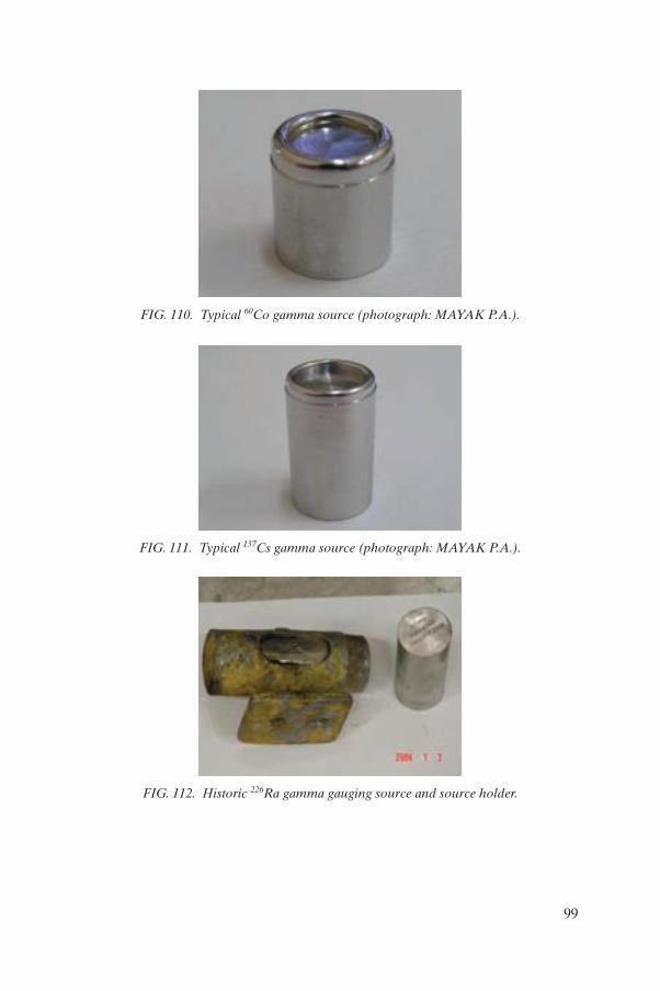
FIG. 110. Typical 60Co gamma source (photograph: MAYAK P.A.).
FIG. 111. Typical 137Cs gamma source (photograph: MAYAK P.A.).
FIG. 112. Historic 226Ra gamma gauging source and source holder.
99
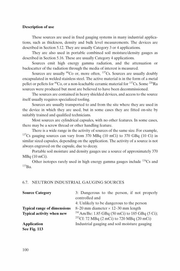
Description of use
These sources are used in fixed gauging systems in many industrial applica-tions, such as thickness, density and bulk level measurements. The devices are described in Section 5.12. They are usually Category 3 or 4 applications.
They are also used in portable combined soil moisture/density gauges as described in Section 5.16. These are usually Category 4 applications.
Sources emit high energy gamma radiation, and the attenuation or backscatter of the radiation through the media of interest is measured.
Sources are usually 60Co or, more often, 137Cs. Sources are usually doubly encapsulated in welded stainless steel. The active material is in the form of a metal pellet or pellets for 60Co, or a non-leachable ceramic material for 137Cs. Some 226Ra sources were produced but most are believed to have been decommissioned.
The sources are contained in heavy shielded devices, and access to the source itself usually requires specialized tooling.
Sources are usually transported to and from the site where they are used in the device in which they are used, but in some cases they are fitted on-site by suitably trained and qualified technicians.
Most sources are cylindrical capsules, with no other features. In some cases, there may be a screw thread or other handling feature.
There is a wide range in the activity of sources of the same size. For example, 137Cs gauging sources can vary from 370 MBq (10 mCi) to 370 GBq (10 Ci) in similar sized capsules, depending on the application. The activity of a source is not always engraved on the capsule, due to decay.
Portable soil moisture and density gauges use a source of approximately 370 MBq (10 mCi).
Other isotopes rarely used in high energy gamma gauges include 134Cs and 133Ba.
6.7. NEUTRON INDUSTRIAL GAUGING SOURCES
Source Category 3: Dangerous to the person, if not properly controlled and 4: Unlikely to be dangerous to the person
Typical range of dimensions 8–20 mm diameter × 12–30 mm lengthTypical activity when new 241Am/Be: 1.85 GBq (50 mCi) to 185 GBq (5 Ci);
252Cf: 72 MBq (2 mCi) to 720 MBq (20 mCi)Application Industrial gauging and soil moisture gaugingSee Fig. 113
100
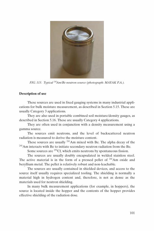
Description of use
These sources are used in fixed gauging systems in many industrial appli-cations for bulk moisture measurement, as described in Section 5.15. These are usually Category 3 applications.
They are also used in portable combined soil moisture/density gauges, as described in Section 5.16. These are usually Category 4 applications.
They are often used in conjunction with a density measurement using a gamma source.
The sources emit neutrons, and the level of backscattered neutron radiation is measured to derive the moisture content.
These sources are usually 241Am mixed with Be. The alpha decay of the 241Am interacts with Be to initiate secondary neutron radiation from the Be.
Some sources are 252Cf, which emits neutrons by spontaneous fission.The sources are usually doubly encapsulated in welded stainless steel.
The active material is in the form of a pressed pellet of 241Am oxide and beryllium metal. The pellet is relatively robust and non-leachable.
The sources are usually contained in shielded devices, and access to the source itself usually requires specialized tooling. The shielding is normally a material high in hydrogen content and, therefore, is not as dense as the materials used for neutron shielding.
In many bulk measurement applications (for example, in hoppers), the source is located inside the hopper and the contents of the hopper provides effective shielding of the radiation dose.
FIG. 113. Typical 241Am/Be neutron source (photograph: MAYAK P.A.).
101
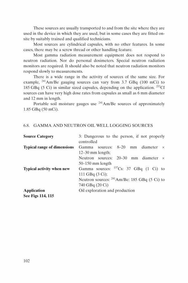
These sources are usually transported to and from the site where they are used in the device in which they are used, but in some cases they are fitted on-site by suitably trained and qualified technicians.
Most sources are cylindrical capsules, with no other features. In some cases, there may be a screw thread or other handling feature.
Most gamma radiation measurement equipment does not respond to neutron radiation. Nor do personal dosimeters. Special neutron radiation monitors are required. It should also be noted that neutron radiation monitors respond slowly to measurements.
There is a wide range in the activity of sources of the same size. For example, 241Am/Be gauging sources can vary from 3.7 GBq (100 mCi) to 185 GBq (5 Ci) in similar sized capsules, depending on the application. 252Cf sources can have very high dose rates from capsules as small as 6 mm diameter and 12 mm in length.
Portable soil moisture gauges use 241Am/Be sources of approximately 1.85 GBq (50 mCi).
6.8. GAMMA AND NEUTRON OIL WELL LOGGING SOURCES
Source Category 3: Dangerous to the person, if not properly controlled
Typical range of dimensions Gamma sources: 8–20 mm diameter ×12–30 mm length;Neutron sources: 20–30 mm diameter × 50–150 mm length
Typical activity when new Gamma sources: 137Cs: 37 GBq (1 Ci) to 111 GBq (3 Ci);Neutron sources: 241Am/Be: 185 GBq (5 Ci) to 740 GBq (20 Ci)
Application Oil exploration and productionSee Figs 114, 115
102
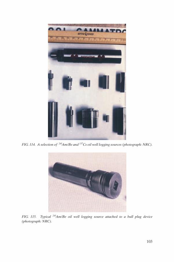
FIG. 114. A selection of 241Am/Be and 137Cs oil well logging sources (photograph: NRC).
FIG. 115. Typical 241Am/Be oil well logging source attached to a bull plug device (photograph: NRC).
103
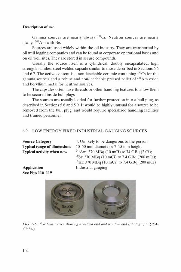
Description of use
Gamma sources are nearly always 137Cs. Neutron sources are nearly always 241Am with Be.
Sources are used widely within the oil industry. They are transported by oil well logging companies and can be found at corporate operational bases and on oil well sites. They are stored in secure compounds.
Usually the source itself is a cylindrical, doubly encapsulated, high strength stainless steel welded capsule similar to those described in Sections 6.6 and 6.7. The active content is a non-leachable ceramic containing 137Cs for the gamma sources and a robust and non-leachable pressed pellet of 241Am oxide and beryllium metal for neutron sources.
The capsules often have threads or other handling features to allow them to be secured inside bull plugs.
The sources are usually loaded for further protection into a bull plug, as described in Sections 5.8 and 5.9. It would be highly unusual for a source to be removed from the bull plug, and would require specialized handling facilities and trained personnel.
6.9. LOW ENERGY FIXED INDUSTRIAL GAUGING SOURCES
Source Category 4: Unlikely to be dangerous to the personTypical range of dimensions 10–50 mm diameter × 7–15 mm heightTypical activity when new 241Am: 370 MBq (10 mCi) to 74 GBq (2 Ci);
90Sr: 370 MBq (10 mCi) to 7.4 GBq (200 mCi); 85Kr: 370 MBq (10 mCi) to 7.4 GBq (200 mCi)
Application Industrial gauging See Figs 116–119
FIG. 116. 90Sr beta source showing a welded end and window end (photograph: QSA-Global).
104
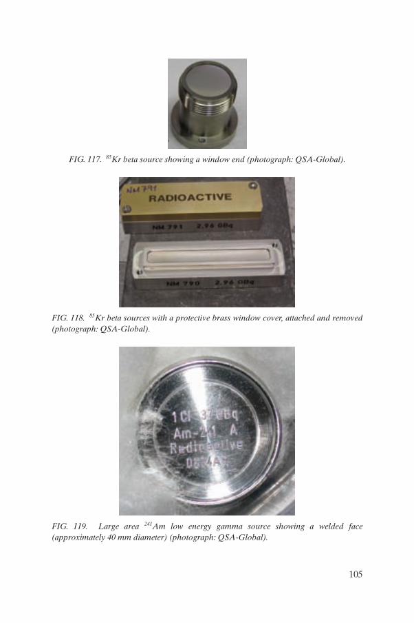
FIG. 117. 85Kr beta source showing a window end (photograph: QSA-Global).
FIG. 118. 85Kr beta sources with a protective brass window cover, attached and removed (photograph: QSA-Global).
FIG. 119. Large area 241Am low energy gamma source showing a welded face (approximately 40 mm diameter) (photograph: QSA-Global).
105
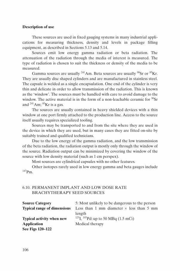
Description of use
These sources are used in fixed gauging systems in many industrial appli-cations for measuring thickness, density and levels in package filling equipment, as described in Sections 5.13 and 5.14.
Sources emit low energy gamma radiation or beta radiation. The attenuation of the radiation through the media of interest is measured. The type of radiation is chosen to suit the thickness or density of the media to be measured.
Gamma sources are usually 241Am. Beta sources are usually 90Sr or 85Kr. They are usually disc shaped cylinders and are manufactured in stainless steel. The capsule is welded as a single encapsulation. One end of the cylinder is very thin and delicate in order to allow transmission of the radiation. This is known as the ‘window’. The sources must be handled with care to avoid damage to the window. The active material is in the form of a non-leachable ceramic for 90Sr and 241Am; 85Kr is a gas.
The sources are usually contained in heavy shielded devices with a thin window at one port firmly attached to the production line. Access to the source itself usually requires specialized tooling.
Sources may be transported to and from the site where they are used in the device in which they are used, but in many cases they are fitted on-site by suitably trained and qualified technicians.
Due to the low energy of the gamma radiation, and the low transmission of the beta radiation, the radiation output is mostly only through the window of the source. Radiation output can be minimized by covering the window of the source with low density material (such as 1 cm perspex).
Most sources are cylindrical capsules with no other features. Other isotopes rarely used in low energy gamma and beta gauges include
147Pm.
6.10. PERMANENT IMPLANT AND LOW DOSE RATE BRACHYTHERAPY SEED SOURCES
Source Category 5: Most unlikely to be dangerous to the personTypical range of dimensions Less than 1 mm diameter × less than 5 mm
lengthTypical activity when new 125I, 103Pd: up to 50 MBq (1.5 mCi) Application Medical therapySee Figs 120–122
106
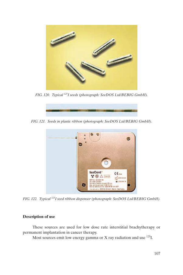
Description of use
These sources are used for low dose rate interstitial brachytherapy or permanent implantation in cancer therapy.
Most sources emit low energy gamma or X ray radiation and use 125I.
FIG. 120. Typical 125I seeds (photograph: SeeDOS Ltd/BEBIG GmbH).
FIG. 121. Seeds in plastic ribbon (photograph: SeeDOS Ltd/BEBIG GmbH).
FIG. 122. Typical 125I seed ribbon dispenser (photograph: SeeDOS Ltd/BEBIG GmbH).
107
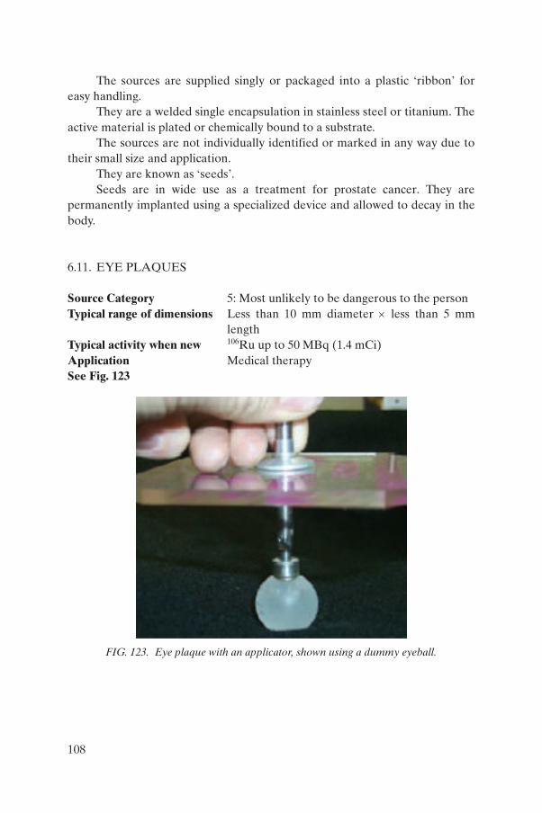
The sources are supplied singly or packaged into a plastic ‘ribbon’ for easy handling.
They are a welded single encapsulation in stainless steel or titanium. The active material is plated or chemically bound to a substrate.
The sources are not individually identified or marked in any way due to their small size and application.
They are known as ‘seeds’.Seeds are in wide use as a treatment for prostate cancer. They are
permanently implanted using a specialized device and allowed to decay in the body.
6.11. EYE PLAQUES
Source Category 5: Most unlikely to be dangerous to the personTypical range of dimensions Less than 10 mm diameter × less than 5 mm
lengthTypical activity when new 106Ru up to 50 MBq (1.4 mCi)Application Medical therapySee Fig. 123
FIG. 123. Eye plaque with an applicator, shown using a dummy eyeball.
108
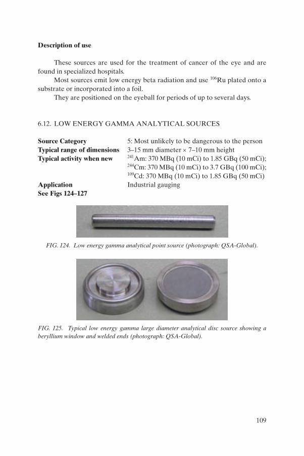
Description of use
These sources are used for the treatment of cancer of the eye and are found in specialized hospitals.
Most sources emit low energy beta radiation and use 106Ru plated onto a substrate or incorporated into a foil.
They are positioned on the eyeball for periods of up to several days.
6.12. LOW ENERGY GAMMA ANALYTICAL SOURCES
Source Category 5: Most unlikely to be dangerous to the personTypical range of dimensions 3–15 mm diameter × 7–10 mm heightTypical activity when new 241Am: 370 MBq (10 mCi) to 1.85 GBq (50 mCi);
244Cm: 370 MBq (10 mCi) to 3.7 GBq (100 mCi); 109Cd: 370 MBq (10 mCi) to 1.85 GBq (50 mCi)
Application Industrial gauging See Figs 124–127
FIG. 124. Low energy gamma analytical point source (photograph: QSA-Global).
FIG. 125. Typical low energy gamma large diameter analytical disc source showing a beryllium window and welded ends (photograph: QSA-Global).
109
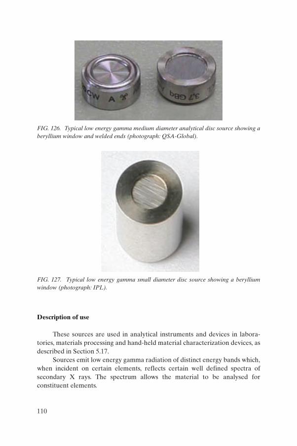
Description of use
These sources are used in analytical instruments and devices in labora-tories, materials processing and hand-held material characterization devices, as described in Section 5.17.
Sources emit low energy gamma radiation of distinct energy bands which, when incident on certain elements, reflects certain well defined spectra of secondary X rays. The spectrum allows the material to be analysed for constituent elements.
FIG. 126. Typical low energy gamma medium diameter analytical disc source showing a beryllium window and welded ends (photograph: QSA-Global).
FIG. 127. Typical low energy gamma small diameter disc source showing a beryllium window (photograph: IPL).
110
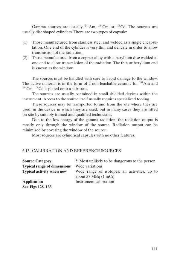
Gamma sources are usually 241Am, 244Cm or 109Cd. The sources are usually disc shaped cylinders. There are two types of capsule:
(1) Those manufactured from stainless steel and welded as a single encapsu-lation. One end of the cylinder is very thin and delicate in order to allow transmission of the radiation.
(2) Those manufactured from a copper alloy with a beryllium disc welded at one end to allow transmission of the radiation. The thin or beryllium end is known as the window.
The sources must be handled with care to avoid damage to the window. The active material is in the form of a non-leachable ceramic for 241Am and 244Cm. 109Cd is plated onto a substrate.
The sources are usually contained in small shielded devices within the instrument. Access to the source itself usually requires specialized tooling.
These sources may be transported to and from the site where they are used, in the device in which they are used, but in many cases they are fitted on-site by suitably trained and qualified technicians.
Due to the low energy of the gamma radiation, the radiation output is mostly only through the window of the source. Radiation output can be minimized by covering the window of the source.
Most sources are cylindrical capsules with no other features.
6.13. CALIBRATION AND REFERENCE SOURCES
Source Category 5: Most unlikely to be dangerous to the personTypical range of dimensions Wide variationsTypical activity when new Wide range of isotopes: all activities, up to
about 37 MBq (1 mCi)Application Instrument calibrationSee Figs 128–133
111
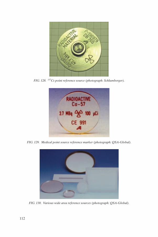
FIG. 128. 137Cs point reference source (photograph: Schlumberger).
FIG. 129. Medical point source reference marker (photograph: QSA-Global).
FIG. 130. Various wide area reference sources (photograph: QSA-Global).
112
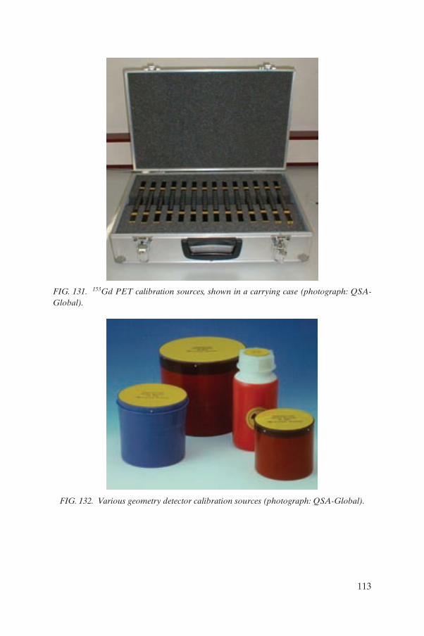
FIG. 131. 153Gd PET calibration sources, shown in a carrying case (photograph: QSA-Global).
FIG. 132. Various geometry detector calibration sources (photograph: QSA-Global).
113
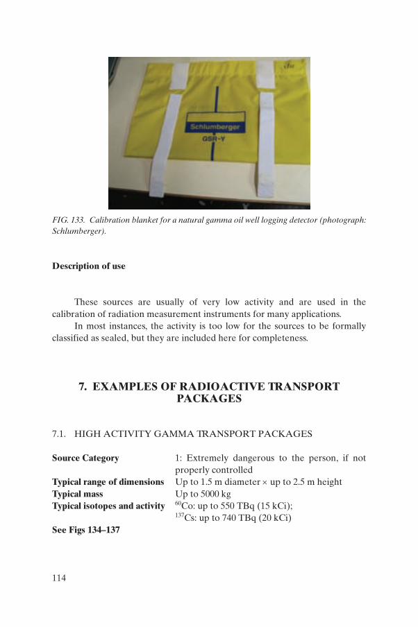
Description of use
These sources are usually of very low activity and are used in the calibration of radiation measurement instruments for many applications.
In most instances, the activity is too low for the sources to be formally classified as sealed, but they are included here for completeness.
7. EXAMPLES OF RADIOACTIVE TRANSPORT PACKAGES
7.1. HIGH ACTIVITY GAMMA TRANSPORT PACKAGES
Source Category 1: Extremely dangerous to the person, if not properly controlled
Typical range of dimensions Up to 1.5 m diameter × up to 2.5 m heightTypical mass Up to 5000 kgTypical isotopes and activity 60Co: up to 550 TBq (15 kCi);
137Cs: up to 740 TBq (20 kCi)See Figs 134–137
FIG. 133. Calibration blanket for a natural gamma oil well logging detector (photograph: Schlumberger).
114
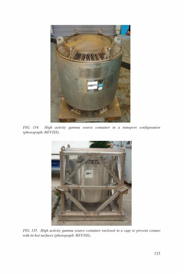
FIG. 134. High activity gamma source container in a transport configuration (photograph: REVISS).
FIG. 135. High activity gamma source container enclosed in a cage to prevent contact with its hot surfaces (photograph: REVISS).
115
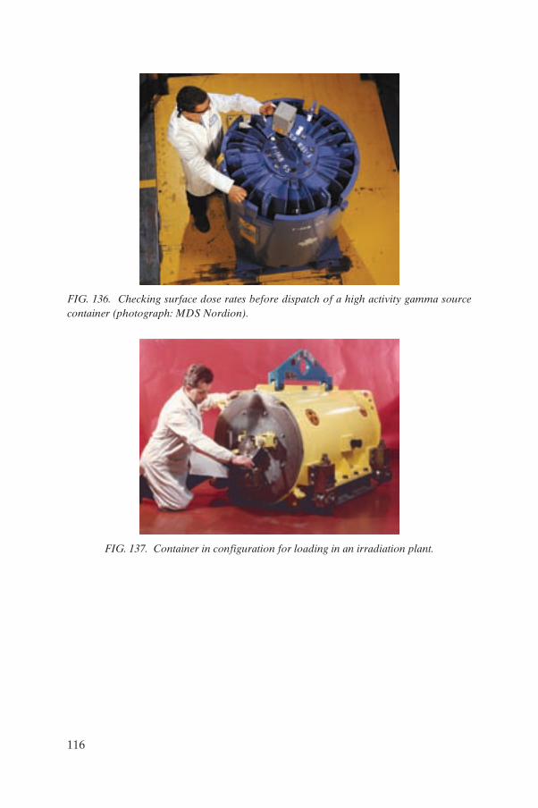
FIG. 136. Checking surface dose rates before dispatch of a high activity gamma source container (photograph: MDS Nordion).
FIG. 137. Container in configuration for loading in an irradiation plant.
116
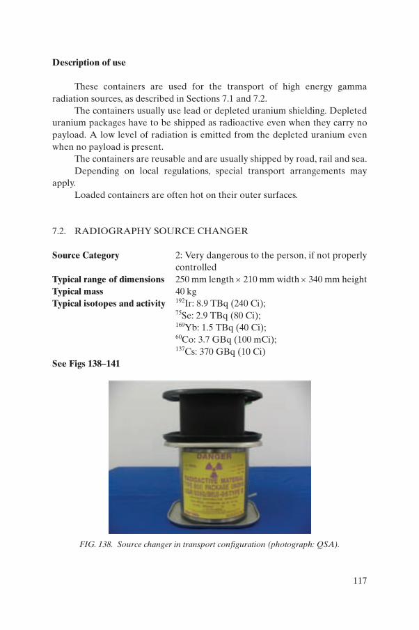
Description of use
These containers are used for the transport of high energy gamma radiation sources, as described in Sections 7.1 and 7.2.
The containers usually use lead or depleted uranium shielding. Depleted uranium packages have to be shipped as radioactive even when they carry no payload. A low level of radiation is emitted from the depleted uranium even when no payload is present.
The containers are reusable and are usually shipped by road, rail and sea.Depending on local regulations, special transport arrangements may
apply.Loaded containers are often hot on their outer surfaces.
7.2. RADIOGRAPHY SOURCE CHANGER
Source Category 2: Very dangerous to the person, if not properly controlled
Typical range of dimensions 250 mm length × 210 mm width × 340 mm heightTypical mass 40 kgTypical isotopes and activity 192Ir: 8.9 TBq (240 Ci);
75Se: 2.9 TBq (80 Ci); 169Yb: 1.5 TBq (40 Ci); 60Co: 3.7 GBq (100 mCi); 137Cs: 370 GBq (10 Ci)
See Figs 138–141
FIG. 138. Source changer in transport configuration (photograph: QSA).
117
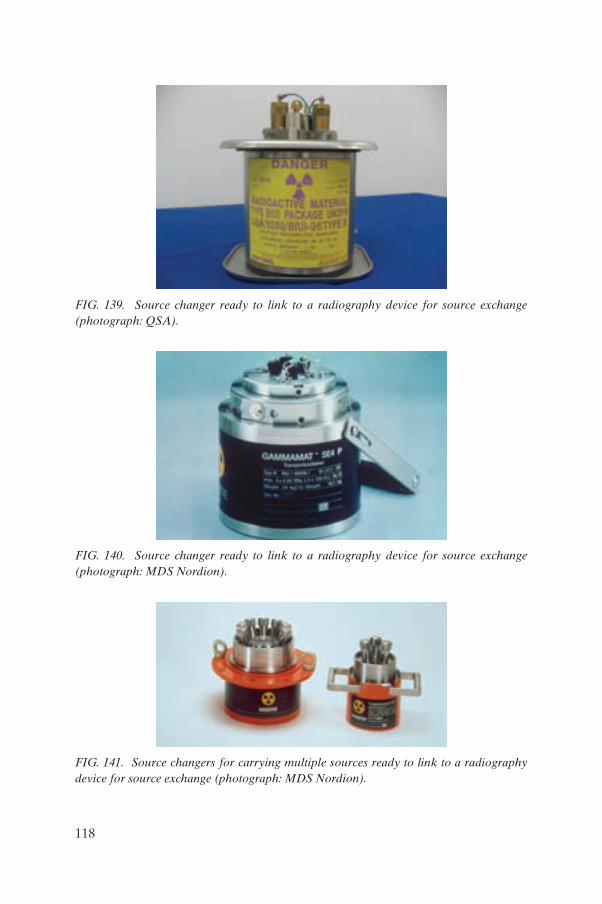
FIG. 139. Source changer ready to link to a radiography device for source exchange (photograph: QSA).
FIG. 140. Source changer ready to link to a radiography device for source exchange (photograph: MDS Nordion).
FIG. 141. Source changers for carrying multiple sources ready to link to a radiography device for source exchange (photograph: MDS Nordion).
118
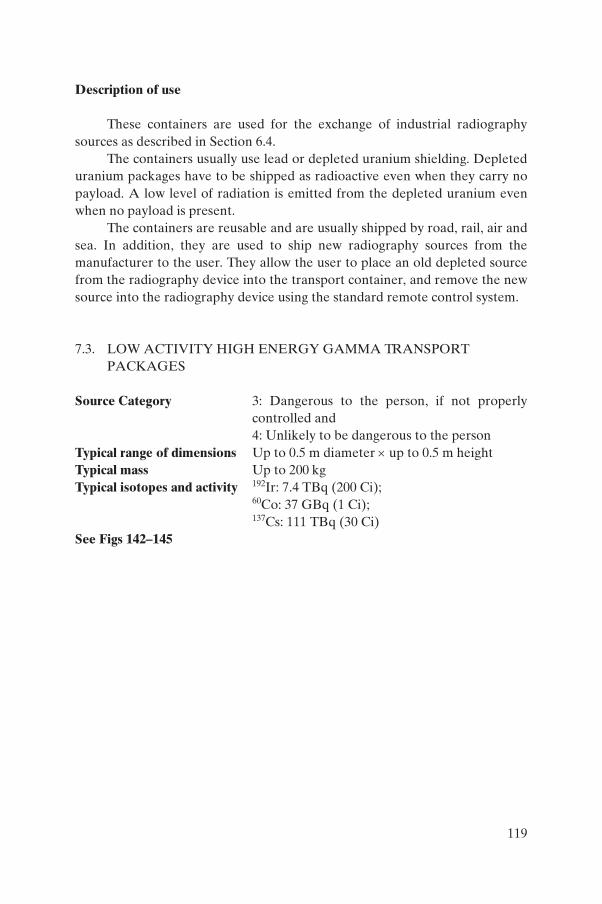
Description of use
These containers are used for the exchange of industrial radiography sources as described in Section 6.4.
The containers usually use lead or depleted uranium shielding. Depleted uranium packages have to be shipped as radioactive even when they carry no payload. A low level of radiation is emitted from the depleted uranium even when no payload is present.
The containers are reusable and are usually shipped by road, rail, air and sea. In addition, they are used to ship new radiography sources from the manufacturer to the user. They allow the user to place an old depleted source from the radiography device into the transport container, and remove the new source into the radiography device using the standard remote control system.
7.3. LOW ACTIVITY HIGH ENERGY GAMMA TRANSPORT PACKAGES
Source Category 3: Dangerous to the person, if not properly controlled and 4: Unlikely to be dangerous to the person
Typical range of dimensions Up to 0.5 m diameter × up to 0.5 m heightTypical mass Up to 200 kgTypical isotopes and activity 192Ir: 7.4 TBq (200 Ci);
60Co: 37 GBq (1 Ci); 137Cs: 111 TBq (30 Ci)
See Figs 142–145
119
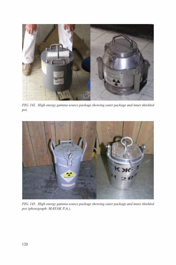
FIG. 142. High energy gamma source package showing outer package and inner shielded pot.
FIG. 143. High energy gamma source package showing outer package and inner shielded pot (photograph: MAYAK P.A.).
120
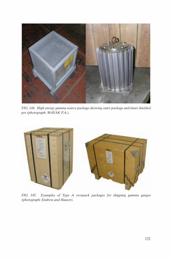
FIG. 144. High energy gamma source package showing outer package and inner shielded pot (photograph: MAYAK P.A.).
FIG. 145. Examples of Type A overpack packages for shipping gamma gauges (photograph: Endress and Hauser).
121
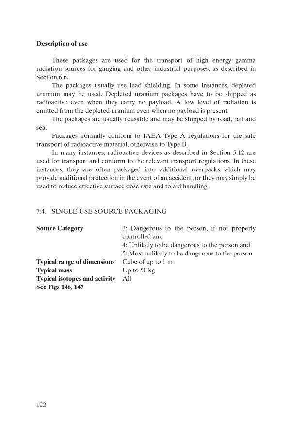
Description of use
These packages are used for the transport of high energy gamma radiation sources for gauging and other industrial purposes, as described in Section 6.6.
The packages usually use lead shielding. In some instances, depleted uranium may be used. Depleted uranium packages have to be shipped as radioactive even when they carry no payload. A low level of radiation is emitted from the depleted uranium even when no payload is present.
The packages are usually reusable and may be shipped by road, rail and sea.
Packages normally conform to IAEA Type A regulations for the safe transport of radioactive material, otherwise to Type B.
In many instances, radioactive devices as described in Section 5.12 are used for transport and conform to the relevant transport regulations. In these instances, they are often packaged into additional overpacks which may provide additional protection in the event of an accident, or they may simply be used to reduce effective surface dose rate and to aid handling.
7.4. SINGLE USE SOURCE PACKAGING
Source Category 3: Dangerous to the person, if not properly controlled and 4: Unlikely to be dangerous to the person and 5: Most unlikely to be dangerous to the person
Typical range of dimensions Cube of up to 1 mTypical mass Up to 50 kgTypical isotopes and activity All See Figs 146, 147
122
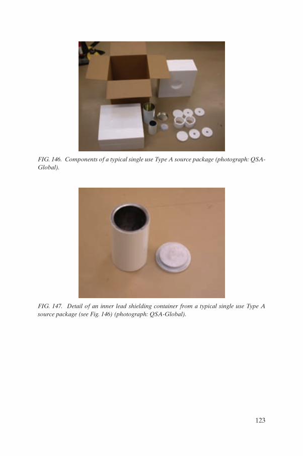
FIG. 146. Components of a typical single use Type A source package (photograph: QSA-Global).
FIG. 147. Detail of an inner lead shielding container from a typical single use Type A source package (see Fig. 146) (photograph: QSA-Global).
123
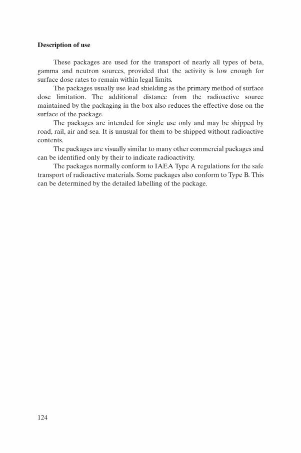
Description of use
These packages are used for the transport of nearly all types of beta, gamma and neutron sources, provided that the activity is low enough for surface dose rates to remain within legal limits.
The packages usually use lead shielding as the primary method of surface dose limitation. The additional distance from the radioactive source maintained by the packaging in the box also reduces the effective dose on the surface of the package.
The packages are intended for single use only and may be shipped by road, rail, air and sea. It is unusual for them to be shipped without radioactive contents.
The packages are visually similar to many other commercial packages and can be identified only by their to indicate radioactivity.
The packages normally conform to IAEA Type A regulations for the safe transport of radioactive materials. Some packages also conform to Type B. This can be determined by the detailed labelling of the package.
124
Appendix I
RADIATION BASICS
I.1. WHAT IS RADIATION?
Radiation is generally defined as energy in the form of photons or particles propagating through space. Radiation, for the purposes of this publi-cation, refers to ionizing radiation which is capable of ionizing biological materials and therefore causing damage to living cells.
In the context of radioactive sources, ionizing radiation comprises gamma and X ray photons, and alpha, beta and neutron particles.
I.2. FORMS OF IONIZING RADIATION
There are five forms of ionizing radiation relevant to the context of this manual (see Fig. 148):
(1) Alpha radiation: This is particulate radiation of relatively large mass and energy. It has a relatively short range. It is absorbed in 1–2 cm of air, or on a sheet of paper or the dead tissue of the outer layer of human skin.
(2) Beta radiation: This is an electron emitted by an atom’s nucleus. The particle is of very low mass and has a greater range than alpha radiation. Beta radiation can be absorbed by a sheet of plastic, glass or metal. It can penetrate the outer skin and be absorbed into the living tissue, causing ionization which can be harmful.
(3) Gamma radiation: This is a high energy photon emitted from an atom’s nucleus. The photon is of negligible mass and has a great range. It interacts with the electrons of material into which it is absorbed, causing ionization which can be harmful to living tissue. Typically, dense material, such as lead or steel, may be used for shielding.
(4) Neutron radiation: This is a neutron emitted from an atom’s nucleus. It is relatively small and light in atomic terms, has no charge and is normally of high energy and, therefore, has quite a long range. Because neutrons have no charge, they do not directly cause ionization, however, when they collide with the nuclei of atoms in an absorbing material they can damage them and make them unstable, which means that they can be very damaging to living tissue. They penetrate many materials relatively easily and can be shielded by hydrogenous material, such as water or paraffin.
125
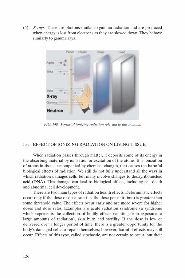
(5) X rays: These are photons similar to gamma radiation and are produced when energy is lost from electrons as they are slowed down. They behave similarly to gamma rays.
I.3. EFFECT OF IONIZING RADIATION ON LIVING TISSUE
When radiation passes through matter, it deposits some of its energy in the absorbing material by ionization or excitation of the atoms. It is ionization of atoms in tissue, accompanied by chemical changes, that causes the harmful biological effects of radiation. We still do not fully understand all the ways in which radiation damages cells, but many involve changes to deoxyribonucleic acid (DNA). This damage can lead to biological effects, including cell death and abnormal cell development.
There are two main types of radiation health effects. Deterministic effects occur only if the dose or dose rate (i.e. the dose per unit time) is greater than some threshold value. The effects occur early and are more severe for higher doses and dose rates. Examples are acute radiation syndrome (a syndrome which represents the collection of bodily effects resulting from exposure to large amounts of radiation), skin burn and sterility. If the dose is low or delivered over a longer period of time, there is a greater opportunity for the body’s damaged cells to repair themselves; however, harmful effects may still occur. Effects of this type, called stochastic, are not certain to occur, but their
FIG. 148. Forms of ionizing radiation relevant to this manual.
126
likelihood increases for higher doses, whereas the timing and severity of an effect do not depend on the dose. Examples are cancers of various types.
I.4. LIMITING EXPOSURE TO IONIZING RADIATION
The level of human exposure to ionizing radiation may be controlled and limited in three ways:
(1) Distance;(2) Time;(3) Shielding.
For individuals discovering sources or devices, distance and time are the best methods for controlling and limiting exposure to radiation. For civil authority experts, shielding is an additional method for reducing their exposure.
In the event that an uncontrolled source or device is identified, the public can be protected from radiation by a combination of distance and time. As a general rule, the intensity of the radiation field from a point source of radiation is reduced in proportion to the square of the distance. When sources or devices are identified, it is important to leave the area immediately, in order to minimize time and thus radiation exposure. Shielding of sources or devices should be used based on evaluations by civil authority experts.
I.5. ADDITIONAL INFORMATION
Additional information is provided in Refs [12–14].
127
Appendix II
LIST OF DEVICES AND SUMMARY REFERENCE DATAIN SECTION 5
TABLE 1. LIST OF DEVICES AND SUMMARY REFERENCE DATA
ReferenceObject
descriptionCate-gorya
Main application
Secondary application
Typicalmass
Typical dimensions
Remarks
5.1 Industrial sterilization plant
1 Industrial Research n.a. Building of 100 m × 200 m × 50 m
5.2 Teletherapy machine
1 Medical Research 500–1000 kg
4 m length × 2 m width × 3 m height
5.3 Blood irradiator
1 Medical 1500–3500 kg
1 m length × 1 m width × 1.5 m height
5.4 Multibeam teletherapy machine (gamma knife)
1 Medical 20 000 kg 4–5 m length × 2 m width × 2.5 m height
Shielded device
5.5 Small scale sample irradiator
1 Research 1000–6000 kg
1.5 m length × 1.5 m width × 2 m height
5.6 Seed irradiator 1 Agricultural Industrial Chamber (dis-
mounted): 3000–
6000 kg
1.5 m length × 1.5 m width × 2 m height
May be assembled on vehicles
5.7 Radioisotope thermoelectric generators (RTGs)
1a Other Other 500–1000 kg
1.5 m length × 1.5 m width × 1.5 m height
Excluding pacemakers
5.8 Gamma oil well logging bull plug
2 Industrial 500–1000 g 20–60 mm diameter × 100–150 mm length
5.9 Neutron oil well logging bull plug
2 Industrial 400–1000 g 20–60 mm diameter × 100 × 200 mm length
128
5.10 Gamma radiography projector
2 Industrial 8–35 kg 350 mm length × 200 mm width × 240 mm height
Used for Ir-192, Se-75 sources
5.10 Gamma radiography source changer
2 Industrial 40 kg 250 mm length × 210 mm width × 340 mm height
‘Source changer’
5.10 Gamma radiography projector (Co-60)
2 Industrial 100–200 kg 900 mm length × 900 mm width × 900 mm height
Semi-portable Co-60 device
5.11 Gamma radiography pipeline crawler
2 Industrial 50–100 kg 800–1500 mm length × 400 mm width × 400 mm height
5.12 High energy gamma density, thickness and level gauge
3 Industrial 20–400 kg 200–400 mm diameter × 300–700 mm length
5.13 Low energy gamma density, thickness and level gauge
3 Industrial 20–50 kg 200–400 mm diameter, 300–700 mm length
5.14 Beta density and thickness gauge
4 Industrial 10–20 kg 100–300 mm length × 100 × 300 mm width × 100 × 300 mm height
5.15 Bulk material moisture gauge
3 Industrial 10–1000 kg 300–1000 mm length × 300 × 500 mm width × 300 × 500 mm height
5.16 Soil moisture/ density gauge
4 Industrial Agricultural 30 kg 200 mm length × 300 mm width × 1000 mm height
TABLE 1. LIST OF DEVICES AND SUMMARY REFERENCE DATA (cont.)
ReferenceObject
descriptionCate-gorya
Main application
Secondary application
Typicalmass
Typical dimensions
Remarks
129
5.17 X ray fluorescence analyser
5 Industrial Research Hand-held: 1–2 kg
Laboratory and process
control: 20–100 kg
Hand-held: 200 mm length × 100 mm width × 100 mm heightLaboratory and process control: 500 mm length × 500 mm width × 1500 mm height
5.18 Brachytherapy machine
2 Medical 50–250 kg 300–600 mm length × 300 × 600 mm width × 800 × 1500 mm height
5.19 Static eliminator
4 Industrial Bars: up to 2 kg
Guns: up to 500 g
Bars: up to 2000 mm length × 30 mm width × 10 mm depth Guns: 30 mm diameter × 80 mm length
5.20 Radioactive lightning conductor rod
5 Industrial Household 2–10 kg 100–300 mm diameter × 500 × 1000 mm length
5.21 Self-luminous sign
5 Industrial 1–10 kg Up to 600 mm length × up to 200 mm width × up to 100 mm depth
5.22 Smoke detector
5 Household Industrial 100–300 g 100–150 mm diameter × 15–30 mm height
a ‘Category’ refers to the IAEA Categories defined in Section 4.8, where Category 1 is extremely dangerous to the person and Category 5 is most unlikely to be dangerous to the person.
TABLE 1. LIST OF DEVICES AND SUMMARY REFERENCE DATA (cont.)
ReferenceObject
descriptionCate-gorya
Main application
Secondary application
Typicalmass
Typical dimensions
Remarks
130
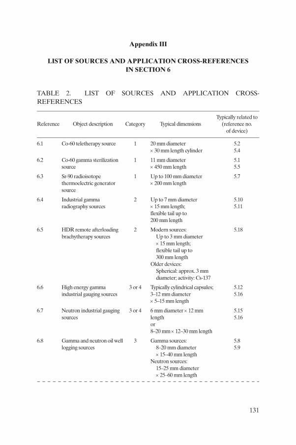
Appendix III
LIST OF SOURCES AND APPLICATION CROSS-REFERENCESIN SECTION 6
TABLE 2. LIST OF SOURCES AND APPLICATION CROSS-REFERENCES
Reference Object description Category Typical dimensionsTypically related to
(reference no. of device)
6.1 Co-60 teletherapy source 1 20 mm diameter × 30 mm length cylinder
5.25.4
6.2 Co-60 gamma sterilization source
1 11 mm diameter × 450 mm length
5.15.5
6.3 Sr-90 radioisotope thermoelectric generator source
1 Up to 100 mm diameter × 200 mm length
5.7
6.4 Industrial gamma radiography sources
2 Up to 7 mm diameter × 15 mm length; flexible tail up to 200 mm length
5.105.11
6.5 HDR remote afterloading brachytherapy sources
2 Modern sources:Up to 3 mm diameter × 15 mm length; flexible tail up to 300 mm length
Older devices:Spherical: approx. 3 mm diameter; activity: Cs-137
5.18
6.6 High energy gamma industrial gauging sources
3 or 4 Typically cylindrical capsules; 3–12 mm diameter × 5–15 mm length
5.125.16
6.7 Neutron industrial gauging sources
3 or 4 6 mm diameter × 12 mm length or 8–20 mm × 12–30 mm length
5.155.16
6.8 Gamma and neutron oil well logging sources
3 Gamma sources:8–20 mm diameter × 15–40 mm length
Neutron sources:15–25 mm diameter × 25–60 mm length
5.85.9
131
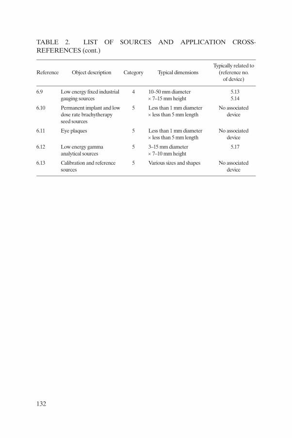
6.9 Low energy fixed industrial gauging sources
4 10–50 mm diameter × 7–15 mm height
5.135.14
6.10 Permanent implant and low dose rate brachytherapy seed sources
5 Less than 1 mm diameter × less than 5 mm length
No associated device
6.11 Eye plaques 5 Less than 1 mm diameter × less than 5 mm length
No associated device
6.12 Low energy gamma analytical sources
5 3–15 mm diameter × 7–10 mm height
5.17
6.13 Calibration and reference sources
5 Various sizes and shapes No associated device
TABLE 2. LIST OF SOURCES AND APPLICATION CROSS-REFERENCES (cont.)
Reference Object description Category Typical dimensionsTypically related to
(reference no. of device)
132

REFERENCES
[1] INTERNATIONAL ATOMIC ENERGY AGENCY, Manual for First Responders to a Radiological Emergency, IAEA-EPR-First Responders, IAEA, Vienna (2006).
[2] INTERNATIONAL ATOMIC ENERGY AGENCY, Preparedness and Response for a Nuclear or Radiological Emergency, Safety Requirements, GS-R-2, IAEA, Vienna (2002).
[3] INTERNATIONAL ATOMIC ENERGY AGENCY, Regulations for the Safe Transport of Radioactive Material, IAEA Safety Standards Series No. TS-R-1, IAEA, Vienna (2005).
[4] INTERNATIONAL ATOMIC ENERGY AGENCY, The Radiological Accident in Goiânia, IAEA, Vienna (1988).
[5] INTERNATIONAL ATOMIC ENERGY AGENCY, Accidental Overexposure of Radiotherapy Patients in Bialystok, IAEA, Vienna (2004).
[6] INTERNATIONAL ATOMIC ENERGY AGENCY, The Radiological Accident in Yanango, IAEA, Vienna (2000).
[7] INTERNATIONAL ATOMIC ENERGY AGENCY, The Radiological Accident in Lilo, IAEA, Vienna (2000).
[8] INTERNATIONAL ATOMIC ENERGY AGENCY, The Radiological Accident in Samut Prakarn, IAEA, Vienna (2002).
[9] INTERNATIONAL ATOMIC ENERGY AGENCY, Technical Data on Nucleonic Gauges, IAEA-TECDOC-1459, IAEA, Vienna (2005).
[10] INTERNATIONAL ATOMIC ENERGY AGENCY, Radiation Protection and Safety in Industrial Radiography, Safety Reports Series No. 13, IAEA, Vienna (1999).
[11] INTERNATIONAL ATOMIC ENERGY AGENCY, Categorization of Radio-active Sources, IAEA Safety Standards Series No. RS-G-1.9, IAEA, Vienna (2005).
[12] INTERNATIONAL ATOMIC ENERGY AGENCY, Sealed Radioactive Sources Toolkit, Information Booklet, IAEA, Vienna (2005).
[13] INTERNATIONAL ATOMIC ENERGY AGENCY, Radiation, People and the Environment, Information Booklet, IAEA, Vienna (2004).
[14] INTERNATIONAL ATOMIC ENERGY AGENCY, Security of Radioactive Sources: Interim Guidance for Comment, IAEA-TECDOC-1355, IAEA, Vienna (2003).
133
DEFINITIONS
The definitions given below may not necessarily conform to definitions adopted elsewhere for international use. More general terms relating to radiation protection may be found in the IAEA Safety Glossary: Version 2.0 at the following web site: http://www-ns.iaea.org/standards/safety-glossary.htm
activity. The rate at which nuclear transformations occur in a radioactive material. Used as a measure of the amount of a radionuclide present. Unit becquerel, symbol Bq. 1 Bq = 1 transformation per second. Formerly expressed in curie (Ci); activity values may be given in Ci (with the equivalent in Bq in parentheses) if they are being quoted from a reference that uses Ci as the unit. Unit of activity, equal to 3.7 × 10¹⁰ Bq (exactly).
alpha particle. A particle consisting of two protons plus two neutrons (i.e. the nucleus of a helium atom) emitted by a radionuclide.
atom. Unit of matter consisting of a single nucleus surrounded by a number of electrons equal to the number of protons in the nucleus. The smallest portion of an element that can combine chemically with other atoms.
atomic number. The number of protons in the nucleus of an atom. Symbol Z.
becquerel. See activity.
beta particle. An electron or proton which has been emitted by an atomic nucleus or neutron in a nuclear transformation.
brachytherapy. The use of a sealed radioactive source in or on the body for treating certain types of cancer.
depleted uranium. Uranium containing a lesser mass percentage of 235U than the 0.7% found in natural uranium. A by-product from the production of enriched uranium. Used as radiation shielding in radioactive transport packaging and some devices.
deterministic effect. A health effect of radiation for which generally a threshold level of dose exists above which the severity of the effect is greater for a higher dose. Such an effect is described as a ‘severe deterministic effect’ if
134
it is fatal or life threatening or results in a permanent injury that reduces quality of life.
device. A piece of machinery or instrument in which a radioactive source is used, and which safely houses the source. The manufacture of devices generally conforms to national or international safety standards.
disposal. In relation to radioactive waste, emplacement in an appropriate facility without the intention of retrieval.
electromagnetic radiation. Radiation consisting of electrical and magnetic fields oscillating at right angles to each other. Ranges from very long wavelengths (low energy), such as radio waves, through intermediate wavelengths, such as visible light, to very short wavelengths (high energy), such as gamma rays.
electron. A stable elementary particle having a negative electric charge of 1.6 × 10⁻¹⁹ C and a mass of 9.1 × 10⁻³¹ kg.
free radical. An uncharged atom or group of atoms having one or more unpaired electrons which were part of a chemical bond. Generally very reactive in a chemical sense.
gamma ray. Penetrating electromagnetic radiation emitted by an atomic nucleus during radioactive decay and having wavelengths much shorter than those of visible light.
half-life. For a radionuclide, the time required for the activity to decrease, by radioactive decay processes, by half. Symbol: T1/2.
ionization. The process by which an atom or molecule acquires or loses an electric charge. The production of ions.
ionizing radiation. For the purposes of radiation protection, radiation capable of producing ion pairs in biological material(s). Examples are alpha particles, gamma rays, X rays and neutrons.
irradiation. The act of being exposed to radiation. It can be intentional, for example, through industrial irradiation to sterilize medical equipment; or accidental, for example, through proximity to a source that emits
135

radiation. Irradiation does not usually result in radioactive contami-nation, but damage can occur depending on the dose received.
isotopes. Nuclides with the same number of protons but different numbers of neutrons. Not a synonym for nuclide.
mass number. The number of protons plus neutrons in the nucleus of an atom; abbreviation A.
molecule. A group of atoms bonded to each other chemically. The smallest portion of a substance that can exist by itself and retain the properties of the substance.
neutron. An elementary particle having no electric charge, a mass of about 1.67 × 10⁻²⁷ kg and a mean lifetime of about 1000 seconds.
nuclear medicine. The use of radionuclides for diagnosing or treating disease in patients.
nucleus (of an atom). The positively charged central portion of an atom. Contains the protons and neutrons.
nuclide. A species of atom characterized by the number of protons and neutrons and the energy state of the nucleus.
photon. A quantum of electromagnetic radiation.
radiation. Energy, in the form of waves or particles, propagating through space. Frequently used for ionizing radiation in the present text, except when it is necessary to avoid confusion with non-ionizing radiation.
radiation protection (or radiological protection). The protection of people from the effects of exposure to ionizing radiation, and the means for achieving this.
radioactive. Exhibiting radioactivity. For legal and regulatory purposes, the meaning of radioactive is often restricted to those materials designated in national law or by a regulatory body as being subject to regulatory control because of their radioactivity.
136
radioactive source. A means of containment of radioactive material such that the radioactive material remains protected in a leaktight capsule but the radiation is allowed to be emitted for its intended purpose. Also known as a sealed source or source. Radioactive sources are manufactured in accordance with international law for integrity.
radioactivity. The phenomenon whereby atoms undergo spontaneous random disintegration, usually accompanied by the emission of radiation.
radionuclide. A radioactive nuclide.
radiotherapy. The use of radiation beams for treating disease, usually cancer, in patients.
regulatory body. An organization designated by a national government as having legal authority for regulating nuclear, radiation, radioactive waste and transport safety.
risk. The probability of a specified health effect occurring in a person or group as a result of exposure to radiation.
sealed source. See radioactive source.
source. See radioactive source.
transport package. A container in which sealed sources are transported. Transport packages conform to international regulations for the safe transport of radioactive materials.
X ray. Penetrating electromagnetic radiation emitted by an atom when electrons in the atom lose energy, and having wavelengths much shorter than those of visible light, see gamma ray.
137

CONTRIBUTORS TO DRAFTING AND REVIEW
Al-Mughrabi, M. International Atomic Energy Agency
Ambrose, J. Department of Homeland Security, United States of America
Andrievskaya, L.A. Federal Atomic Energy, Russian Federation
Benz, D. Endress+Hauser, Germany
Calvante, V.L. Comissão Nacional de Energia Nuclear, Brazil
Garcia, A. Europol
Ghosh, J.K. Board of Radiation and Isotope Technology, India
Harris, T. Nuclear Regulatory Commission, United States of America
McAlpin, J. Los Alamos National Laboratory, United States of America
Neubauer, J. International Atomic Energy Agency
Parfitt, J. Reviss Services, United Kingdom
Schlueck, R.K. New York Fire Department, United States of America
Shaddad, I.A.R. Atomic Energy Commission, Sudan
Stevens, R. LSS Technical Data Assessment, United States of America
Strempel, S. AEA Technology QSA GmbH, Germany
Svahn, B. Radiation Protection Authority, Sweden
138