Embed Size (px)
Citation preview

PSS 21H-3A3 B3
I/A Series® HARDWAREProduct Specifications
DCS Fieldbus Module for Migration of Bailey® Systems
I/A Series® distributed control system (DCS) Fieldbus Modules allow migration from Bailey® Network 90 and INFI 90® process input and output (I/O) components to an I/A Series process control system.
FEATURES
Key features of the I/A Series system DCS FBMs are:
DCS FBMs plug directly into an existing Bailey module mounting unit (nest) to replace controller and slave module cards
Migration from proprietary DCS to a state-of-the-art open I/A Series system
Advanced I/A Series system control with single point of configuration
More direct control performance than any gateway device offers
Single vendor service and supply.
The I/A Series system DCS FBM family provides a migration path from the Bailey systems process input and output components to I/A Series display and supervisory functions. This can save significant cost over total system replacement by preserving existing process interface and wiring, and by minimizing process downtime.
No additional communication devices are required. No multi-vendor communication software licensing is required. The I/A Series system DCS FBM family replaces the Bailey controller and/or slave module devices. Once integrated, the process is controlled entirely by the advanced I/A Series algorithm set.
PSS 21H-3A3 B3Page 2
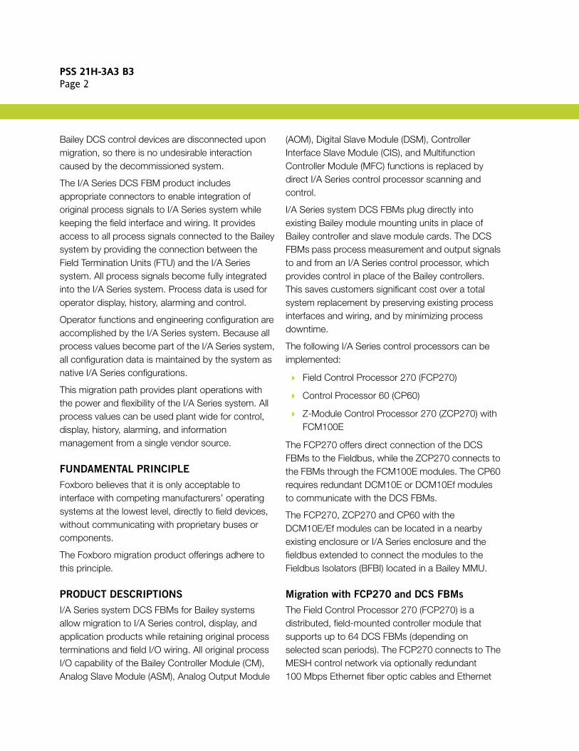
Bailey DCS control devices are disconnected upon migration, so there is no undesirable interaction caused by the decommissioned system.
The I/A Series DCS FBM product includes appropriate connectors to enable integration of original process signals to I/A Series system while keeping the field interface and wiring. It provides access to all process signals connected to the Bailey system by providing the connection between the Field Termination Units (FTU) and the I/A Series system. All process signals become fully integrated into the I/A Series system. Process data is used for operator display, history, alarming and control.
Operator functions and engineering configuration are accomplished by the I/A Series system. Because all process values become part of the I/A Series system, all configuration data is maintained by the system as native I/A Series configurations.
This migration path provides plant operations with the power and flexibility of the I/A Series system. All process values can be used plant wide for control, display, history, alarming, and information management from a single vendor source.
FUNDAMENTAL PRINCIPLE
Foxboro believes that it is only acceptable to interface with competing manufacturers’ operating systems at the lowest level, directly to field devices, without communicating with proprietary buses or components.
The Foxboro migration product offerings adhere to this principle.
PRODUCT DESCRIPTIONS
I/A Series system DCS FBMs for Bailey systems allow migration to I/A Series control, display, and application products while retaining original process terminations and field I/O wiring. All original process I/O capability of the Bailey Controller Module (CM), Analog Slave Module (ASM), Analog Output Module
(AOM), Digital Slave Module (DSM), Controller Interface Slave Module (CIS), and Multifunction Controller Module (MFC) functions is replaced by direct I/A Series control processor scanning and control.
I/A Series system DCS FBMs plug directly into existing Bailey module mounting units in place of Bailey controller and slave module cards. The DCS FBMs pass process measurement and output signals to and from an I/A Series control processor, which provides control in place of the Bailey controllers. This saves customers significant cost over a total system replacement by preserving existing process interfaces and wiring, and by minimizing process downtime.
The following I/A Series control processors can be implemented:
Field Control Processor 270 (FCP270)
Control Processor 60 (CP60)
Z-Module Control Processor 270 (ZCP270) with FCM100E
The FCP270 offers direct connection of the DCS FBMs to the Fieldbus, while the ZCP270 connects to the FBMs through the FCM100E modules. The CP60 requires redundant DCM10E or DCM10Ef modules to communicate with the DCS FBMs.
The FCP270, ZCP270 and CP60 with the DCM10E/Ef modules can be located in a nearby existing enclosure or I/A Series enclosure and the fieldbus extended to connect the modules to the Fieldbus Isolators (BFBI) located in a Bailey MMU.
Migration with FCP270 and DCS FBMs
The Field Control Processor 270 (FCP270) is a distributed, field-mounted controller module that supports up to 64 DCS FBMs (depending on selected scan periods). The FCP270 connects to The MESH control network via optionally redundant 100 Mbps Ethernet fiber optic cables and Ethernet
PSS 21H-3A3 B3Page 3
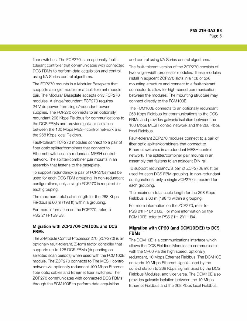
fiber switches. The FCP270 is an optionally fault-tolerant controller that communicates with connected DCS FBMs to perform data acquisition and control using I/A Series control algorithms.
The FCP270 mounts in a Modular Baseplate that supports a single module or a fault-tolerant module pair. The Modular Baseplate accepts only FCP270 modules. A single/redundant FCP270 requires 24 V dc power from single/redundant power supplies. The FCP270 connects to an optionally redundant 268 Kbps Fieldbus for communications to the DCS FBMs and provides galvanic isolation between the 100 Mbps MESH control network and the 268 Kbps local Fieldbus.
Fault-tolerant FCP270 modules connect to a pair of fiber optic splitter/combiners that connect to Ethernet switches in a redundant MESH control network. The splitter/combiner pair mounts in an assembly that fastens to the baseplate.
To support redundancy, a pair of FCP270s must be used for each DCS FBM grouping. In non-redundant configurations, only a single FCP270 is required for each grouping.
The maximum total cable length for the 268 Kbps Fieldbus is 60 m (198 ft) within a grouping.
For more information on the FCP270, refer to PSS 21H-1B9 B3.
Migration with ZCP270/FCM100E and DCS
FBMs
The Z-Module Control Processor 270 (ZCP270) is an optionally fault-tolerant, Z-form factor controller that supports up to 128 DCS FBMs (depending on selected scan periods) when used with the FCM100E module. The ZCP270 connects to The MESH control network via optionally redundant 100 Mbps Ethernet fiber optic cables and Ethernet fiber switches. The ZCP270 communicates with connected DCS FBMs through the FCM100E to perform data acquisition
and control using I/A Series control algorithms.
The fault-tolerant version of the ZCP270 consists of two single-width processor modules. These modules install in adjacent ZCP270 slots in a 1x8 or 2x8 mounting structure and connect to a fault-tolerant connector to allow for high-speed communication between the modules. The mounting structure may connect directly to the FCM100E.
The FCM100E connects to an optionally redundant 268 Kbps Fieldbus for communications to the DCS FBMs and provides galvanic isolation between the 100 Mbps MESH control network and the 268 Kbps local Fieldbus.
Fault-tolerant ZCP270 modules connect to a pair of fiber optic splitter/combiners that connect to Ethernet switches in a redundant MESH control network. The splitter/combiner pair mounts in an assembly that fastens to an adjacent DIN rail.
To support redundancy, a pair of ZCP270s must be used for each DCS FBM grouping. In non-redundant configurations, only a single ZCP270 is required for each grouping.
The maximum total cable length for the 268 Kbps Fieldbus is 60 m (198 ft) within a grouping.
For more information on the ZCP270, refer to PSS 21H-1B10 B3. For more information on the FCM100E, refer to PSS 21H-2Y11 B4.
Migration with CP60 (and DCM10E/Ef) to DCS
FBMs
The DCM10E is a communications interface which allows the DCS Fieldbus Modules to communicate with the CP60 via the high speed, optionally redundant, 10 Mbps Ethernet Fieldbus. The DCM10E converts 10 Mbps Ethernet signals used by the control station to 268 Kbps signals used by the DCS Fieldbus Modules, and vice versa. The DCM10E also provides galvanic isolation between the 10 Mbps Ethernet Fieldbus and the 268 Kbps local Fieldbus.
PSS 21H-3A3 B3Page 4
The DCM10Es are used in pairs for redundancy. A DCM10E (or pair of DCM10Es) can support up to 64 DCS Fieldbus Modules. Up to 30 DCM10E pairs can be connected to the Ethernet Fieldbus. The maximum total number of DCS FBMs on one CP60 is 120 (depending on selected scan periods).
The DCM10Ef Fieldbus Communications Module is a fiber optic communications interface which allows the DCS Fieldbus Modules to communicate with the CP60 over extended distances using fiber optic cabling. The DCM10Ef provides expanded networking, easy customizing, and greater overall cabling distances in a fiber optic network. This configuration is ideally suited for sites in which groups of DCS Fieldbus Modules are to be spread apart over greater distances. DCM10Ef modules are used with multiport fiber optic converters (hubs), which connect to the CP60 via the high speed, optionally redundant, 10 Mbps Ethernet Fieldbus. Up to six groupings of baseplate-mounted DCM10Ef modules and DCS Fieldbus Modules can be linked to each optionally redundant hub, for a maximum of 120 DCS Fieldbus Modules per CP60 (depending on selected scan periods).
To support redundancy, a pair of DCM10Ef modules must be used for each DCS Fieldbus Module grouping. In non-redundant configurations, only a single DCM10Ef is required for each grouping. Signal transmission distances up to 2 kilometers (1.24 miles) are possible between the WFCM10Ef modules and hubs, providing for wide distribution of the DCS Fieldbus Module equipment groupings. Extended transmission distances using fiber optic cabling are also possible within the groupings, and between the hubs and the CP60.
Controller Module (CIS01, CIS02, COM01,
COM02, COM03, COM04, QRC01, QRS01,
QRS02)
A Controller Module (CM) connects directly to an
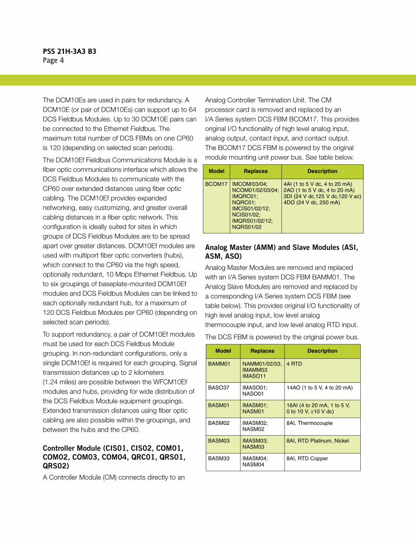
Analog Controller Termination Unit. The CM processor card is removed and replaced by an I/A Series system DCS FBM BCOM17. This provides original I/O functionality of high level analog input, analog output, contact input, and contact output. The BCOM17 DCS FBM is powered by the original module mounting unit power bus. See table below.
Analog Master (AMM) and Slave Modules (ASI,
ASM, ASO)
Analog Master Modules are removed and replaced with an I/A Series system DCS FBM BAMM01. The Analog Slave Modules are removed and replaced by a corresponding I/A Series system DCS FBM (see table below). This provides original I/O functionality of high level analog input, low level analog thermocouple input, and low level analog RTD input.
The DCS FBM is powered by the original power bus.
Model Replaces Description
BCOM17 IMCOM/03/04; NCOM01/02/03/04;IMQRC01; NQRC01; IMCIS01/02/12; NCIS01/02; IMQRS01/02/12; NQRS01/02
4AI (1 to 5 V dc, 4 to 20 mA) 2AO (1 to 5 V dc, 4 to 20 mA) 3DI (24 V dc,125 V dc,120 V ac)4DO (24 V dc, 250 mA)
Model Replaces Description
BAMM01 NAMM01/02/03; IMAMM03IMASO11
4 RTD
BASO37 IMASO01; NASO01
14AO (1 to 5 V, 4 to 20 mA)
BASM01 IMASM01; NASM01
16AI (4 to 20 mA, 1 to 5 V,0 to 10 V, ±10 V dc)
BASM02 IMASM02; NASM02
8AI, Thermocouple
BASM03 IMASM03; NASM03
8AI, RTD Platinum, Nickel
BASM33 IMASM04; NASM04
8AI, RTD Copper
PSS 21H-3A3 B3Page 5
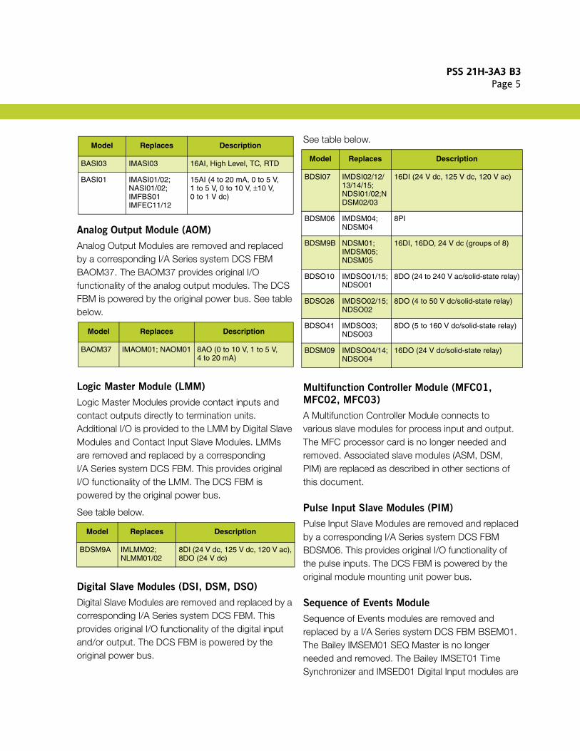
Analog Output Module (AOM)
Analog Output Modules are removed and replaced by a corresponding I/A Series system DCS FBM BAOM37. The BAOM37 provides original I/O functionality of the analog output modules. The DCS FBM is powered by the original power bus. See table below.
Logic Master Module (LMM)
Logic Master Modules provide contact inputs and contact outputs directly to termination units. Additional I/O is provided to the LMM by Digital Slave Modules and Contact Input Slave Modules. LMMs are removed and replaced by a corresponding I/A Series system DCS FBM. This provides original I/O functionality of the LMM. The DCS FBM is powered by the original power bus.
See table below.
Digital Slave Modules (DSI, DSM, DSO)
Digital Slave Modules are removed and replaced by a corresponding I/A Series system DCS FBM. This provides original I/O functionality of the digital input and/or output. The DCS FBM is powered by the original power bus.
See table below.
Multifunction Controller Module (MFC01,
MFC02, MFC03)
A Multifunction Controller Module connects to various slave modules for process input and output. The MFC processor card is no longer needed and removed. Associated slave modules (ASM, DSM, PIM) are replaced as described in other sections of this document.
Pulse Input Slave Modules (PIM)
Pulse Input Slave Modules are removed and replaced by a corresponding I/A Series system DCS FBM BDSM06. This provides original I/O functionality of the pulse inputs. The DCS FBM is powered by the original module mounting unit power bus.
Sequence of Events Module
Sequence of Events modules are removed and replaced by a I/A Series system DCS FBM BSEM01. The Bailey IMSEM01 SEQ Master is no longer needed and removed. The Bailey IMSET01 Time Synchronizer and IMSED01 Digital Input modules are
BASI03 IMASI03 16AI, High Level, TC, RTD
BASI01 IMASI01/02; NASI01/02; IMFBS01IMFEC11/12
15AI (4 to 20 mA, 0 to 5 V,1 to 5 V, 0 to 10 V, ±10 V,0 to 1 V dc)
Model Replaces Description
BAOM37 IMAOM01; NAOM01 8AO (0 to 10 V, 1 to 5 V,4 to 20 mA)
Model Replaces Description
BDSM9A IMLMM02; NLMM01/02
8DI (24 V dc, 125 V dc, 120 V ac),8DO (24 V dc)
Model Replaces Description
Model Replaces Description
BDSI07 IMDSI02/12/ 13/14/15; NDSI01/02;NDSM02/03
16DI (24 V dc, 125 V dc, 120 V ac)
BDSM06 IMDSM04; NDSM04
8PI
BDSM9B NDSM01; IMDSM05; NDSM05
16DI, 16DO, 24 V dc (groups of 8)
BDSO10 IMDSO01/15; NDSO01
8DO (24 to 240 V ac/solid-state relay)
BDSO26 IMDSO02/15; NDSO02
8DO (4 to 50 V dc/solid-state relay)
BDSO41 IMDSO03; NDSO03
8DO (5 to 160 V dc/solid-state relay)
BDSM09 IMDSO04/14; NDSO04
16DO (24 V dc/solid-state relay)
PSS 21H-3A3 B3Page 6
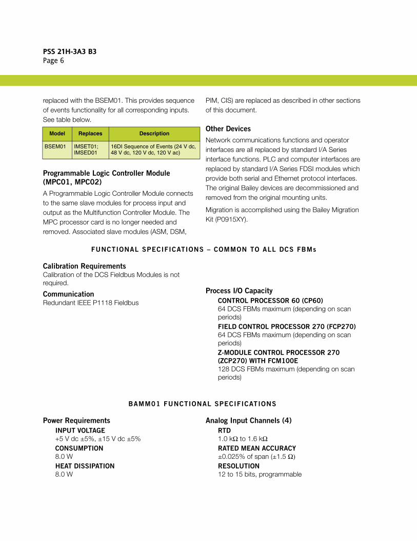
replaced with the BSEM01. This provides sequence of events functionality for all corresponding inputs. See table below.
Programmable Logic Controller Module
(MPC01, MPC02)
A Programmable Logic Controller Module connects to the same slave modules for process input and output as the Multifunction Controller Module. The MPC processor card is no longer needed and removed. Associated slave modules (ASM, DSM,
PIM, CIS) are replaced as described in other sections of this document.
Other Devices
Network communications functions and operator interfaces are all replaced by standard I/A Series interface functions. PLC and computer interfaces are replaced by standard I/A Series FDSI modules which provide both serial and Ethernet protocol interfaces. The original Bailey devices are decommissioned and removed from the original mounting units.
Migration is accomplished using the Bailey Migration Kit (P0915XY).
FUNCTIONAL SPECIFICATIONS – COMMON TO ALL DCS FBMs
Calibration RequirementsCalibration of the DCS Fieldbus Modules is not required.
CommunicationRedundant IEEE P1118 Fieldbus
Process I/O Capacity
CONTROL PROCESSOR 60 (CP60)
64 DCS FBMs maximum (depending on scan periods)FIELD CONTROL PROCESSOR 270 (FCP270)
64 DCS FBMs maximum (depending on scan periods)Z-MODULE CONTROL PROCESSOR 270
(ZCP270) WITH FCM100E
128 DCS FBMs maximum (depending on scan periods)
BAMM01 FUNCTIONAL SPECIFICATIONS
Power Requirements
INPUT VOLTAGE
+5 V dc ±5%, ±15 V dc ±5%CONSUMPTION
8.0 WHEAT DISSIPATION
8.0 W
Analog Input Channels (4)
RTD
1.0 kΩ to 1.6 kΩRATED MEAN ACCURACY
±0.025% of span (±1.5 Ω)RESOLUTION
12 to 15 bits, programmable
Model Replaces Description
BSEM01 IMSET01; IMSED01
16DI Sequence of Events (24 V dc,48 V dc, 120 V dc, 120 V ac)

PSS 21H-3A3 B3Page 7
Analog Input Channels (4) (Continued)
ISOLATION
600 V ac between any channel and earth (ground) or between channels.
NOTEThis does not imply that these channels are
intended for connection to hazardous voltage circuits. Connection of these channels to voltages greater than 30 V ac or 60 V dc violates electrical safety code requirements and may expose users to electrical shock.
BAOM37 FUNCTIONAL SPECIFICATIONS
Power Requirements
INPUT VOLTAGE
+5 V dc ±5%, ±15 V dc ±5%CONSUMPTION
12.0 WHEAT DISSIPATION
12.0 W
Analog Output Channels (8)
RANGE
0 to 10 V dc, 1 to 5 V dc, 0 to 20.4 mA dc
Analog Output Channels (8) (Continued)
RATED MEAN ACCURACY
±0.05% of span (mA range)±0.15% of span (voltage ranges)RESOLUTION
12 bitsOUTPUT LOAD
735 Ω (maximum) mA range1000 Ω (minimum) voltage rangesCOMPLIANCE VOLTAGE
18.6 dc nominal at 20 mA at I/O field terminalsSETTLING TIME
100 ms to settle within 1% band of steady state
BASI01 FUNCTIONAL SPECIFICATIONS
Power Requirements
INPUT VOLTAGE
+5 V dc ±5%, ±15 V dc ±5%CONSUMPTION
5.75 WHEAT DISSIPATION
5.75 W
Analog Input Channels (15)
RANGE
0 to 20 mA dc, 1 to 5 V dc, 0 to 1 V dc,0 to 5 V dc, 0 to 10 V dc, ±10 V dcRATED MEAN ACCURACY
±0.25% of span for 0 to 1 V dc range 0.10% of span for all other rangesRESOLUTION
12 to 15 bits, programmable
BASI03 FUNCTIONAL SPECIFICATIONS
Power Requirements
INPUT VOLTAGE
+5 V dc ±5%, ±15 V dc ±5%CONSUMPTION
6.0 WHEAT DISSIPATION
6.0 W
Analog Input Channels (16)Independently configured
RANGE
TC, RTD, 0 to 100 mV, ±100 mV, 1 to 5 V dc,0 to 5 V dc, 0 to 10 V dc, ±10 V dcRATED MEAN ACCURACY
±0.05% of span
PSS 21H-3A3 B3Page 8
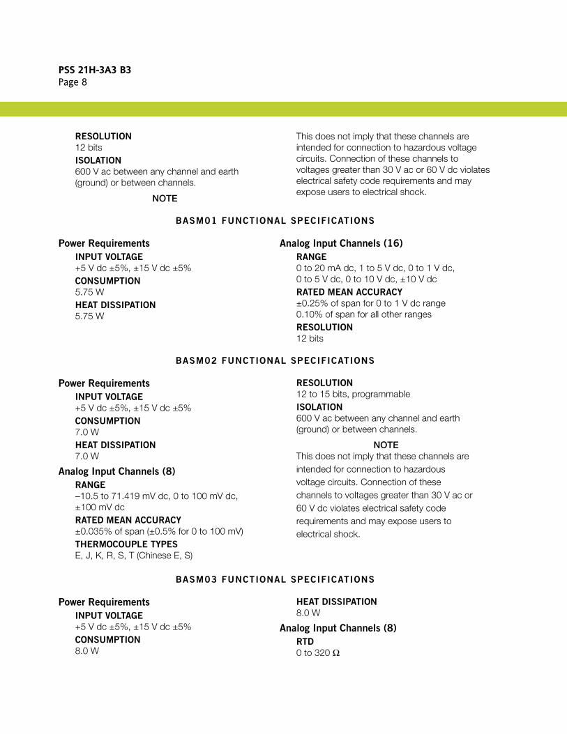
RESOLUTION
12 bitsISOLATION
600 V ac between any channel and earth (ground) or between channels.
NOTE
This does not imply that these channels are intended for connection to hazardous voltage circuits. Connection of these channels to voltages greater than 30 V ac or 60 V dc violates electrical safety code requirements and may expose users to electrical shock.
BASM01 FUNCTIONAL SPECIFICATIONS
Power Requirements
INPUT VOLTAGE
+5 V dc ±5%, ±15 V dc ±5%CONSUMPTION
5.75 WHEAT DISSIPATION
5.75 W
Analog Input Channels (16)
RANGE
0 to 20 mA dc, 1 to 5 V dc, 0 to 1 V dc,0 to 5 V dc, 0 to 10 V dc, ±10 V dcRATED MEAN ACCURACY
±0.25% of span for 0 to 1 V dc range 0.10% of span for all other rangesRESOLUTION
12 bits
BASM02 FUNCTIONAL SPECIFICATIONS
Power Requirements
INPUT VOLTAGE
+5 V dc ±5%, ±15 V dc ±5%CONSUMPTION
7.0 WHEAT DISSIPATION
7.0 W
Analog Input Channels (8)
RANGE
−10.5 to 71.419 mV dc, 0 to 100 mV dc, ±100 mV dcRATED MEAN ACCURACY
±0.035% of span (±0.5% for 0 to 100 mV)THERMOCOUPLE TYPES
E, J, K, R, S, T (Chinese E, S)
RESOLUTION
12 to 15 bits, programmableISOLATION
600 V ac between any channel and earth (ground) or between channels.
NOTEThis does not imply that these channels are intended for connection to hazardous voltage circuits. Connection of these channels to voltages greater than 30 V ac or 60 V dc violates electrical safety code requirements and may expose users to electrical shock.
BASM03 FUNCTIONAL SPECIFICATIONS
Power Requirements
INPUT VOLTAGE
+5 V dc ±5%, ±15 V dc ±5%CONSUMPTION
8.0 W
HEAT DISSIPATION
8.0 W
Analog Input Channels (8)
RTD
0 to 320 Ω

PSS 21H-3A3 B3Page 9
RATED MEAN ACCURACY
±0.025% of span (±0.08 Ω)
Analog Input Channels (8) (Continued)
RESOLUTION
12 to 15 bits, programmableISOLATION
600 V ac between any channel and earth (ground) or between channels.
NOTEThis does not imply that these channels are intended for connection to hazardous voltage circuits. Connection of these channels to voltages greater than 30 V ac or 60 V dc violates electrical safety code requirements and may expose users to electrical shock.
BASM33 FUNCTIONAL SPECIFICATIONS
Power Requirements
INPUT VOLTAGE
+5 V dc ±5%, ±15 V dc ±5%CONSUMPTION
8.0 WHEAT DISSIPATION
8.0 W
Analog Input Channels (8)
RTD
0 to 30 Ω CuRATED MEAN ACCURACY
±0.025% of span (±0.08 Ω)
Analog Input Channels (8) (Continued)
RESOLUTION
12 to 15 bits, programmableISOLATION
600 V ac between any channel and earth (ground) or between channels.
NOTEThis does not imply that these channels are intended for connection to hazardous voltage circuits. Connection of these channels to voltages greater than 30 V ac or 60 V dc violates electrical safety code requirements and may expose users to electrical shock.
BASO37 FUNCTIONAL SPECIFICATIONS
Power Requirements
INPUT VOLTAGE
+5 V dc ±5%, ±15 V dc ±5%CONSUMPTION
15.4 WHEAT DISSIPATION
15.4 W
Analog Output Channels (14)
RANGE
1 to 5 V dc, 4 to 20.4 mA dc
RATED MEAN ACCURACY
±0.25% of span (4 to 20 mA range) ±0.15% of span (1 to 5 V dc range)RESOLUTION
12 bitsOUTPUT LOAD
750 Ω (maximum) 4 to 20 mA range 350 Ω (minimum) 1 to 5 V dc rangeCOMPLIANCE VOLTAGE
18.6 dc nominal at 20 mA at I/O field terminalsSETTLING TIME
100 ms to settle within 1% band of steady state
BCOM17 FUNCTIONAL SPECIFICATIONS
Power Requirements
INPUT VOLTAGE
+5 V dc ±5%, ±15 V dc ±5%
CONSUMPTION
5.75 W

PSS 21H-3A3 B3Page 10
HEAT DISSIPATION
5.75 W
Analog Input Channels (4 Channels)
RANGE
1 to 5 V dc, 4 to 20 mA dcRATED MEAN ACCURACY
±0.05% of spanRESOLUTION
12 to 15 bits, programmable
Discrete Input Channels (3)
OPEN CIRCUIT VOLTAGE
Range 124 V dc, 125 V dc, 120 V ac (supplied at termination panel)Range 224 V dc, 125 V dc (supplied at termination panel)
SHORT CIRCUIT CURRENT
Range 12.0 mA at 24 V dc; 6.0 mA at 125 V dc; 3.0 mA at 120 V acRange 22.0 mA at 24 V dc; 6.0 mA at 125 V dc
ON-STATE RESISTANCE
1 kΩ (maximum)OFF-STATE RESISTANCE
200 kΩ (minimum)
Discrete Input Channels (3)
INPUT SWITCHING LEVELS
Jumper selectHigh Level Range 120 V dc minimum (24 V dc);100 V dc minimum (125 V dc);100 Vrms minimum (120 V ac)
High Level Range 210 V dc minimum (24 V dc);35 V dc minimum (125 V dc)Low Level Range 110 V dc maximum (24 V dc);50 V dc maximum (125 V dc);50 Vrms maximum (120 V ac)
Low Level Range 21.7 V dc maximum (24 V dc);5.6 V dc maximum (125 V dc)
Analog Output Channels (2)
RANGE
1 to 5 V dc, 4 to 20.4 mA dcRATED MEAN ACCURACY
±0.05% of spanRESOLUTION
12 bitsOUTPUT LOAD
735 Ω (maximum) 4 to 20 mA range 1000 Ω (minimum) 1 to 5 V dc rangeCOMPLIANCE VOLTAGE
18.6 dc nominal at 20 mA at I/O field terminalsSETTLING TIME
100 ms to settle within a 1% band of steady state
Discrete Output Channels (4)Isolated Solid State Switch
APPLIED VOLTAGE
21 to 27 V dcLOAD CURRENT
0.25 A (maximum)OFF-STATE LEAKAGE CURRENT
0.1 mAISOLATION
Discrete input channels and discrete output channels only: 600 V ac, channel to earth (ground)
BDSI07 FUNCTIONAL SPECIFICATIONS
Power Requirements
INPUT VOLTAGE
+5 V dc ±5%CONSUMPTION
5.0 W
HEAT DISSIPATION
5.0 W
Discrete Input Channels (16)
CONTACT INPUT RANGE
Open (off) and Closed (on)
PSS 21H-3A3 B3Page 11
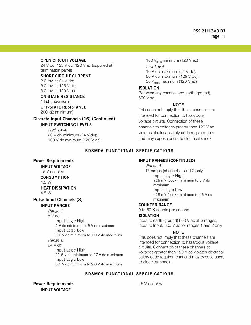
OPEN CIRCUIT VOLTAGE
24 V dc, 125 V dc, 120 V ac (supplied at termination panel)SHORT CIRCUIT CURRENT
2.0 mA at 24 V dc;6.0 mA at 125 V dc;3.0 mA at 120 V acON-STATE RESISTANCE
1 kΩ (maximum)OFF-STATE RESISTANCE
200 kΩ (minimum)
Discrete Input Channels (16) (Continued)
INPUT SWITCHING LEVELS
High Level20 V dc minimum (24 V dc);100 V dc minimum (125 V dc);
100 Vrms minimum (120 V ac)
Low Level10 V dc maximum (24 V dc);50 V dc maximum (125 V dc);50 Vrms maximum (120 V ac)
ISOLATION
Between any channel and earth (ground), 600 V ac
NOTEThis does not imply that these channels are intended for connection to hazardous voltage circuits. Connection of these channels to voltages greater than 120 V ac violates electrical safety code requirements and may expose users to electrical shock.
BDSM06 FUNCTIONAL SPECIFICATIONS
Power Requirements
INPUT VOLTAGE
+5 V dc ±5%CONSUMPTION
4.5 WHEAT DISSIPATION
4.5 W
Pulse Input Channels (8)
INPUT RANGES
Range 15 V dc
Input Logic High4 V dc minimum to 6 V dc maximumInput Logic Low0.0 V dc minimum to 1.0 V dc maximum
Range 224 V dc
Input Logic High21.6 V dc minimum to 27 V dc maximumInput Logic Low0.0 V dc minimum to 2.0 V dc maximum
INPUT RANGES (CONTINUED)
Range 3Preamps (channels 1 and 2 only)
Input Logic High+25 mV (peak) minimum to 5 V dc maximumInput Logic Low−25 mV (peak) minimum to −5 V dc maximum
COUNTER RANGE
0 to 50 K counts per secondISOLATION
Input to earth (ground) 600 V ac all 3 ranges; Input to Input, 600 V ac for ranges 1 and 2 only
NOTEThis does not imply that these channels are intended for connection to hazardous voltage circuits. Connection of these channels to voltages greater than 120 V ac violates electrical safety code requirements and may expose users to electrical shock.
BDSM09 FUNCTIONAL SPECIFICATIONS
Power Requirements
INPUT VOLTAGE
+5 V dc ±5%
PSS 21H-3A3 B3Page 12
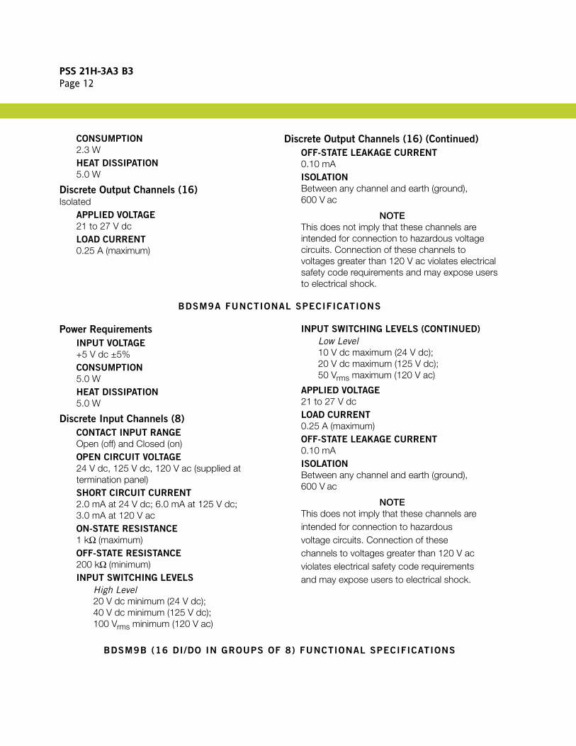
CONSUMPTION
2.3 WHEAT DISSIPATION
5.0 W
Discrete Output Channels (16)Isolated
APPLIED VOLTAGE
21 to 27 V dcLOAD CURRENT
0.25 A (maximum)
Discrete Output Channels (16) (Continued)
OFF-STATE LEAKAGE CURRENT
0.10 mAISOLATION
Between any channel and earth (ground), 600 V ac
NOTEThis does not imply that these channels are intended for connection to hazardous voltage circuits. Connection of these channels to voltages greater than 120 V ac violates electrical safety code requirements and may expose users to electrical shock.
BDSM9A FUNCTIONAL SPECIFICATIONS
Power Requirements
INPUT VOLTAGE
+5 V dc ±5%CONSUMPTION
5.0 WHEAT DISSIPATION
5.0 W
Discrete Input Channels (8)
CONTACT INPUT RANGE
Open (off) and Closed (on)OPEN CIRCUIT VOLTAGE
24 V dc, 125 V dc, 120 V ac (supplied at termination panel)SHORT CIRCUIT CURRENT
2.0 mA at 24 V dc; 6.0 mA at 125 V dc;3.0 mA at 120 V acON-STATE RESISTANCE
1 kΩ (maximum)OFF-STATE RESISTANCE
200 kΩ (minimum)INPUT SWITCHING LEVELS
High Level20 V dc minimum (24 V dc);40 V dc minimum (125 V dc);100 Vrms minimum (120 V ac)
INPUT SWITCHING LEVELS (CONTINUED)
Low Level10 V dc maximum (24 V dc);20 V dc maximum (125 V dc);50 Vrms maximum (120 V ac)
APPLIED VOLTAGE
21 to 27 V dcLOAD CURRENT
0.25 A (maximum)OFF-STATE LEAKAGE CURRENT
0.10 mAISOLATION
Between any channel and earth (ground), 600 V ac
NOTEThis does not imply that these channels are intended for connection to hazardous voltage circuits. Connection of these channels to voltages greater than 120 V ac violates electrical safety code requirements and may expose users to electrical shock.
BDSM9B (16 DI/DO IN GROUPS OF 8) FUNCTIONAL SPECIFICATIONS
PSS 21H-3A3 B3Page 13
Power Requirements
INPUT VOLTAGE
+5 V dc ±5%CONSUMPTION
5.0 WHEAT DISSIPATION
5.0 W
Discrete Input Channels (16)
CONTACT INPUT RANGE
Open (off) and Closed (on)OPEN CIRCUIT VOLTAGE
24 V dc (supplied at termination panel)
Discrete Input Channels (16) (Continued)
SHORT CIRCUIT CURRENT
2.0 mA at 24 V dc; 6.0 mA at 125 V dc;3.0 mA at 120 V acON-STATE RESISTANCE
1 kΩ (maximum)OFF-STATE RESISTANCE
200 kΩ (minimum)INPUT SWITCHING LEVELS
High Level20 V dc minimumLow Level10 V dc maximum
BDSM9B (16 DI/DO IN GROUPS OF 8) FUNCTIONAL SPECIFICATIONS (CONTINUED)
Discrete Output Channels (16) (Continued)
APPLIED VOLTAGE
21 to 27 V dcLOAD CURRENT
0.25 A (maximum)OFF-STATE LEAKAGE CURRENT
0.10 mAISOLATION
Between any channel and earth (ground), 600 V ac
NOTEThis does not imply that these channels are intended for connection to hazardous voltage circuits. Connection of these channels to voltages greater than 120 V ac violates electrical safety code requirements and may expose users to electrical shock.
BDSO10 FUNCTIONAL SPECIFICATIONS
Power Requirements
INPUT VOLTAGE
+5 V dc ±5%CONSUMPTION
2.6 WHEAT DISSIPATION
6.0 W
Discrete Output Channels (8)Isolated
APPLIED VOLTAGE
24 to 240 V acLOAD CURRENT
1.0 A at 70°C
Discrete Output Channels (8) (Continued)
OFF-STATE LEAKAGE CURRENT
17.5 mA at 240 V ac 25°CISOLATION
600 V ac between any channel and earth (ground) or between channels.
NOTEThis does not imply that these channels are intended for connection to hazardous voltage circuits. Connection of these channels to voltages greater than 30 V ac or 60 V dc violates electrical safety code requirements and may expose users to electrical shock.
BDSO26 FUNCTIONAL SPECIFICATIONS
PSS 21H-3A3 B3Page 14
Power Requirements
INPUT VOLTAGE
+5 V dc ±5%CONSUMPTION
3.0 WHEAT DISSIPATION
8.0 W
Discrete Output Channels (8)Isolated
APPLIED VOLTAGE
4 to 50 V dcLOAD CURRENT
1.5 A at 70°C
Discrete Output Channels (8) (Continued)
OFF-STATE LEAKAGE CURRENT
1.0 mA at 70°CISOLATION
600 V ac between any channel and earth (ground) or between channels.
NOTEThis does not imply that these channels are intended for connection to hazardous voltage circuits. Connection of these channels to voltages greater than 30 V ac or 60 V dc violates electrical safety code requirements and may expose users to electrical shock.
BDSO41 FUNCTIONAL SPECIFICATIONS
Power Requirements
INPUT VOLTAGE
+5 V dc ±5%CONSUMPTION
3.0 WHEAT DISSIPATION
6.0 W
Discrete Output Channels (8)Isolated
APPLIED VOLTAGE
5 to 160 V dcLOAD CURRENT
0.5 A at 70°C
Discrete Output Channels (8) (Continued)
OFF-STATE LEAKAGE CURRENT
2.0 mA at 70°CISOLATION
600 V ac between any channel and earth (ground) or between channels.
NOTEThis does not imply that these channels are intended for connection to hazardous voltage circuits. Connection of these channels to voltages greater than 30 V ac or 60 V dc violates electrical safety code requirements and may expose users to electrical shock.
BSEM01 FUNCTIONAL SPECIFICATIONS
Power Requirements
INPUT VOLTAGE
+5 V dc ±5%CONSUMPTION
5.75 WHEAT DISSIPATION
5.75 W
Discrete Input Channels (16)
CONTACT INPUT RANGE
Open (off) and Closed (on)OPEN CIRCUIT VOLTAGE
24 V dc, 48 V dc, 125 V dc, 120 V ac (supplied at
termination panel)SHORT CIRCUIT CURRENT
2.0 mA at 24 V dc;4.0 mA at 48 V dc;6.0 mA at 125 V dc;3.0 mA at 120 V acON-STATE RESISTANCE
1 kΩ (maximum)OFF-STATE RESISTANCE
200 kΩ (minimum)
PSS 21H-3A3 B3Page 15
Discrete Input Channels (16) (Continued)
INPUT SWITCHING LEVELS
High Level20 V dc minimum (24 V dc);40 V dc minimum (48 V dc);100 V dc (125 V dc);100 Vrms minimum (120 V ac)
Low Level10 V dc maximum (24 V dc);20 V dc maximum (48 V dc);50 V dc maximum (125 V dc);
50 V dc maximum (120 V ac)
ISOLATION
Between any channel and earth (ground), 600 V ac
NOTEThis does not imply that these channels are intended for connection to hazardous voltage circuits. Connection of these channels to voltages greater than 120 V ac violates electrical safety code requirements and may expose users to electrical shock.
BFBE2 (FIELDBUS A/B SWITCH EXTENDER) FUNCTIONAL SPECIFICATIONS
Maximum Number of DCS FBMs Driven40
Maximum Length of Local Bus9 m (30 ft)
Maximum Input Power Voltage5.25 V dc
Maximum Operating Current 325 mA
Maximum Power Dissipation1.70 W
Minimum Isolation Voltage2500 V rms
Holdup Time at 5 V dc250 ms
BFBI (FIELDBUS ISOLATOR) FUNCTIONAL SPECIFICATIONS
Maximum Number of DCS FBMs Driven40
Maximum Length of Local Bus9 m (30 ft)
Maximum Input Power Voltage5.25 V dc
Maximum Operating Current325 mA
Maximum Power Dissipation2.75 W
Minimum Isolation Voltage2500 V rms
Holdup Time at 5 V dc250 ms
PSS 21H-3A3 B3Page 16
Invensys10900 Equity DriveHouston, TX 77041United States of Americahttp://www.invensys.com
Global Customer SupportInside U.S.: 1-866-746-6477Outside U.S.: 1-508-549-2424 or contact your local Invensys representative.Website: http://support.ips.invensys.com
Invensys, Foxboro, I/A Series, InFusion, and the Invensys logo are trademarks of Invensys plc, its subsidiaries, and affiliates.All other brands and product names may be the trademarks of their respective owners.
Copyright 1999-2013 Invensys Systems, Inc. All rights reserved. Unauthorized duplication or distribution is strictly prohibited.
MB 21A 0613


![[PSS 21S-10G4 B3] Substation Automation Configuration for ... Infi90 Documentation/FoxIA/21s10g4b3.pdfThe function to generate the ICD, CID and SCD files, which captures all configured](https://img.pdfslide.us/doc/110x75/5ea91e629da39d365b5f0212/pss-21s-10g4-b3-substation-automation-configuration-for-infi90-documentationfoxia21s10g4b3pdfthe.jpg)


![[PSS 21H-2Y12B4] Intrinsically Safe Termination Assembly ... Infi90 Documentation/FoxIA/21h2y12b4.… · baseplate. TERMINATION The baseplate consist of 9-pin sub-D-connectors for](https://img.pdfslide.us/doc/110x75/5ea6c3a364ef4c2eb01e83f5/pss-21h-2y12b4-intrinsically-safe-termination-assembly-infi90-documentationfoxia21h2y12b4.jpg)


![[PSS 21S-10B11 B3] Wonderware Historian - Infi 90 Infi90 Documentation/FoxIA...PSS 21S-10B11 B3 Page 5 The Configuration Editor enables most of the Wonderware Historian configuration](https://img.pdfslide.us/doc/110x75/5e575295d2292c3a996f9b00/pss-21s-10b11-b3-wonderware-historian-infi-90-infi90-documentationfoxia.jpg)