Embed Size (px)
Citation preview
Foxboro Evo™ Process Automation System
Product Specifications
PSS 31H-2SBASEPLT
Standard 200 Series Baseplates
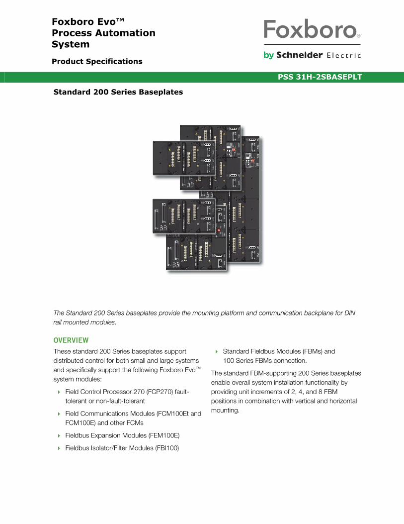
The Standard 200 Series baseplates provide the mounting platform and communication backplane for DIN rail mounted modules.
OVERVIEW
These standard 200 Series baseplates support distributed control for both small and large systems and specifically support the following Foxboro Evo™ system modules:
Field Control Processor 270 (FCP270) fault- tolerant or non-fault-tolerant
Field Communications Modules (FCM100Et and FCM100E) and other FCMs
Fieldbus Expansion Modules (FEM100E)
Fieldbus Isolator/Filter Modules (FBI100)
Standard Fieldbus Modules (FBMs) and 100 Series FBMs connection.
The standard FBM-supporting 200 Series baseplates enable overall system installation functionality by providing unit increments of 2, 4, and 8 FBM positions in combination with vertical and horizontal mounting.

PSS 31H-2SBASEPLTPage 2
FEATURES
Key features of the 200 Series baseplates are:
For FBM-supporting baseplates:
• 2, 4, and 8 module positions in combination with vertical and horizontal mounting
• Field connection for I/O termination assemblies, redundant adapters and module identifiers for each module
• DIP switch for identification of certain Modular Baseplates
• Adding additional 200 Series baseplates without removing the system from service (requires redundant bus)
Connection to the 2 Mbps Module Fieldbus for the Standard Fieldbus Modules, or to a 268 Kbps Fieldbus for the 100 Series FBMs
Splitters/terminators for time strobe and A/B Fieldbus
Connection for optional GPS time strobe for FCP270, and FCM100Et-supporting baseplates
Primary and secondary 24 V dc power and communications connections
Backwards compatibility with existing I/O subsystems allowing for future expansion without additional interface hardware
Keyed positions dedicated to CP or FCM/FBM only, depending on the baseplate type
Passive backplane to increase system reliability.

PSS 31H-2SBASEPLTPage 3
200 SERIES BASEPLATE MOUNTING
Most 200 Series baseplates are available in two basic mounting configurations — horizontal DIN rail mount (see Figure 1) or vertical DIN rail mount (see
Figure 2). Either of these mounting configurations can be employed internal to an enclosure, external to an enclosure, or mounted on a secure DIN rail.
Figure 1. Horizontal DIN Rail Mounted 200 Series Baseplates
FBM and/or FCM8-position, P0926HT
FBM and/or FCM4-position, P0926HM
1 FCP270 and 3 FBM4-position, P0926HJ
FCM/FBM2-position,P0926KE
FCP270 only2-position, P0926HC
2 FCP270 and 2 FBM4-position, P0926HF

PSS 31H-2SBASEPLTPage 4
Figure 2. Vertical DIN Rail Mounted 200 Series Baseplates
MODULE IDENTIFICATION
The baseplate-mounted FBMs, FCM10E, or FCM10Ef are identified to the system software by means of a unique, 6-character string called a “letterbug”. Most FBM-supporting baseplates include a DIP switch to help set this letterbug for the FBMs.
The letterbug for the FCP270s, FCM100Ets and FCM100Es is a soft letterbug entered using the I/A Series® Letterbug Configurator.
The letterbug string for a particular FBM when used with FCMs is established from these three factors:
The first four characters of the FCM10E, FCM10Ef, FCM100Et or FCM100E letterbug.
The number of the FBM baseplate in the group, as set by means of the baseplate Identification (I.D.) DIP switches on each baseplate (see Figure 3).Baseplates should be assumed to have this switch unless otherwise specified in the sections below.
The physical position (1-8) of the module on the baseplate.
FCP270 only2-position,
FCM/FBM2-position,
2 FCP270
FBM 1 FCP270
P0926HW
P0926KH
P0926JF4-position,and/or FCM
P0926HZ4-position,and 2 FBM
P0926JC4-position,and 3 FBM
FBMand/or FCM8-position,P0926JM
FEM100 only2 FCP270
2-position,P0973CG
and2 FEM1004-positionP0973CN
2 FBI1002-position,
2 FBI2002-position,
P0923LR
P0924RT
PSS 31H-2SBASEPLTPage 5
The letterbug string for a particular FBM when used with an FCP280 or FCP270 is established from these four factors:
The first four characters of the letterbug, which may be any letter A-Z or digit 0-9 as long as they do not match the first four characters of the CP letterbug.
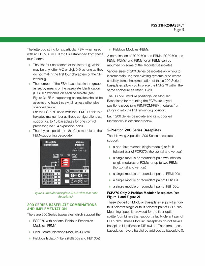
The number of the FBM baseplate in the group, as set by means of the baseplate Identification (I.D.) DIP switches on each baseplate (see Figure 3). FBM-supporting baseplates should be assumed to have this switch unless otherwise specified below.For the FCP270 used with the FEM100, this is a hexadecimal number as these configurations can support up to 16 baseplates for one control processor, via 1-4 expansion ports.
The physical position (1-8) of the module on the FBM-supporting baseplate.
Figure 3. Modular Baseplate ID Switches (For FBM Baseplates)
200 SERIES BASEPLATE COMBINATIONS AND IMPLEMENTATION
There are 200 Series baseplates which support the:
FCP270 with optional Fieldbus Expansion Modules (FEMs)
Field Communications Modules (FCMs)
Fieldbus Isolator/Filters (FBI200s and FBI100s)
Fieldbus Modules (FBMs)
A combination of FCP270s and FBMs, FCP270s and FEMs, FCMs, and FBMs, or all FBMs can be mounted on some of the Modular Baseplates.
Various sizes of 200 Series baseplates allow you to incrementally upgrade existing systems or to create small systems. Implementation of these 200 Series baseplates allow you to place the FCP270 within the same enclosure as other FBMs.
The FCP270 module position(s) on Modular Baseplates for mounting the FCPs are keyed positions preventing FBM/FCM/FEM modules from plugging into the FCP mounting position.
Each 200 Series baseplate and its supported functionality is described below.
2-Position 200 Series Baseplates
The following 2-position 200 Series baseplates support:
a non-fault-tolerant (single module) or fault-tolerant pair of FCP270s (horizontal and vertical)
a single module or redundant pair (two identical single modules) of FCMs, or up to two FBMs (horizontal and vertical)
a single module or redundant pair of FEM100s
a single module or redundant pair of FBI200s
a single module or redundant pair of FBI100s.
FCP270 Only 2-Position Modular Baseplates (see
Figure 1 and Figure 2)
These 2-position Modular Baseplates support a non-fault-tolerant single or fault-tolerant pair of FCP270s. Mounting space is provided for the fiber optic splitter/combiners that support a fault-tolerant pair of FCP270's. These Modular Baseplates do not have a baseplate identification DIP switch. Therefore, these baseplates have a hardwired address as baseplate 0.

PSS 31H-2SBASEPLTPage 6
These Modular Baseplates can be added to existing or new groupings of Modular Baseplates. They can be used to upgrade existing systems with FCP270s or to support FCP270s in a new system.
FEM100 Only 2-Position Expansion Baseplate (see
Figure 2)
This 2-position vertical Expansion Baseplate supports a redundant pair of FEM100s. This baseplate does not have a baseplate identification DIP switch, as it does not require a hardwired address.
This Expansion Baseplate can be added to existing FCP 2-position Modular Baseplates. It is used to expand the number of 200 Series FBMs supported by a FCP270, by providing the capability to add up to four Expanded Fieldbuses which each can support up to thirty-two 200 Series FBMs.
FBI200 and FBI100 2-Position Baseplates (see
Figure 2)
The FBI200 2-position vertical baseplate support a redundant pair of FBI200s, and the FBI1002-position vertical baseplate supports a redundant pair of FBI100s. These Modular Baseplates do not have a baseplate identification DIP switch, as they do not require a hardwired address. The FBI2002-position vertical baseplate does have DIP switches for baud rate mode selection.
FCM/FBM 2-Position Modular Baseplates (see
Figure 1 and Figure 2)
These 2-position Modular Baseplates support FCMs/FBMs. These Modular Baseplates do not have a baseplate identification DIP switch. Therefore, these baseplates have a hardwired address as baseplate 0, with FBM addresses 1 and 2. They can be added to existing or new groupings of Modular Baseplates.
4-Position Modular Baseplates
Seven different 4-position Modular Baseplates support:
a fault-tolerant pair of FCP270s in two positions and the remaining two positions mount FEM100s
a fault-tolerant pair of FCP270s in two positions and the remaining two positions mount FBMs
a single FCP270 in one position and the remaining three (non-fault tolerant) positions mount FBMs
4 FBMs or 2 FCMs and 2 FBMs.
The following applies to these baseplates, with the exception of the FCP270/FEM100 baseplate:
These baseplates have horizontal and vertical versions.
These baseplates have three active baseplate I.D. switches. The third baseplate I.D. switch selects operation as the first-half or second-half of an 8-position Modular Baseplate.
FCP270 and FEM100 4-Position Expansion
Baseplate (see Figure 2)
This Expansion Baseplate is a 4-position Modular Baseplate that supports a fault-tolerant pair of FCP270s in two positions and the remaining two positions mount a redundant pair of FEM100s. Mounting positions are provided for the fiber optic splitter/combiners to support the pair of FCP270's. This Modular Baseplate does not have a baseplate identification DIP switch.
This Modular Baseplate can be used on system installations that require increased I/O capabilities and future upgrades.

PSS 31H-2SBASEPLTPage 7
FCP270 and FBM 4-Position Modular Baseplates
(see Figure 1 and Figure 2)
These Modular Baseplates are 4-position Modular Baseplates that support a fault-tolerant pair of FCP270s in two positions and the remaining two positions mount FBMs. Mounting positions are provided for the fiber optic splitter/combiners to support the pair of FCP270's. These Modular Baseplates have a baseplate identification DIP switch.
These Modular Baseplates can be used on system installations that require increased I/O distribution and future upgrades.
Single FCP270 and FBM 4-Position Modular
Baseplates (see Figure 1 and Figure 2)
These Modular Baseplates support a single FCP270 in one position and the remaining three positions mount FBMs. These Modular Baseplates have a baseplate identification DIP switch.
These Modular Baseplates can be used on system installations that require increased I/O distribution and future upgrades. They are intended to support small system requirements where fault tolerant control is not a requirement.
FBM and/or FCM 4-Position Modular Baseplates
(see Figure 1 and Figure 2)
These 4-position Modular Baseplates supports FBM/FCMs. These Modular Baseplates have a baseplate identification DIP switch.
These Modular Baseplates can be used on system installations that require increased I/O distribution and future upgrades.
8-Position Modular Baseplates
(see Figure 1 and Figure 2)
These 8-position Modular Baseplates support FBMs/FCMs. These Modular Baseplates have a baseplate identification DIP switch.
These Modular Baseplates mount up to 32 FBMs (four 8-position baseplates) in a standard enclosure.
They supersede the P0914XA/XB baseplates and maximize module/baseplate density.
For Intrinsically Safe applications, the use of Pepperl and Fuchs Intrinsic Safe baseplates is recommended. Refer to Intrinsically Safe Termination Assembly - Base Plate (ISTA-*BP*) (PSS 31H-2Y12).
200 SERIES BASEPLATE-TO-BASEPLATE INTERCONNECTIONS
200 Series baseplates are interconnected over a 2 Mbps HDLC, redundant, serial bus (Module Fieldbus). Baseplate inter-connections for A/B Module Fieldbus connections are shielded twisted-pair cables to reduce the effects of noise.
All connectors are labeled to indicate their position and/or function on the 200 Series baseplates (see Figure 4). All module connectors have module guides to ensure the correct insertion of each module into the 200 Series baseplate. Primary and Secondary power connectors are direct connections from the FPS480-24, FPS400-24, FPS240-24, or FPS120-24 power supply. Field I/O connectors provide connections to various termination assemblies for actual connection to the I/O points in the plant.
FCM2F2/4/10 modules provide for fiber optic extension (baseplate-to-baseplate) of the Module Fieldbus.

PSS 31H-2SBASEPLTPage 8
Figure 4. 200 Series Baseplate Connections (Example FBM Baseplate Shown)Field I/O Connectors
Module Connectors
Primary Power, ModuleFieldbus and Time StrobeSplitter/Terminator
Secondary Power, ModuleFieldbus and Time StrobeSplitter/Terminator

PSS 31H-2SBASEPLTPage 9
In addition, another type of termination assembly called the baseplate-mounted termination assembly can mount directly onto the field I/O connectors of an FBM-supporting 200 Series baseplate. These TAs
provide field I/O wiring support for two of their associated FBMs in paired slots (that is, in positions 1 and 2, 3 and 4, 5 and 6, or 7 and 8), as shown in Figure 5.
Figure 5. Baseplate-Mounted Termination Assembly
MODULE PLACEMENT AND REMOVAL
The following rules must be observed with regard to placement of modules (CPs, FCMs, or FBMs) on their corresponding 200 Series baseplates. (Refer to PSS 31H-2S200 and PSS 31H-2COV for the various communication topologies used with the 200 Series baseplates.)
Non-redundant FBMs – Can be placed in any available position
Redundant FBMs – Must be placed in adjacent odd/even paired positions
FCM10E, FCM10Ef, FCM100Et, FCM100E – Modules operating redundantly must be placed in
adjacent odd/even paired positions (one pair per baseplate grouping). When operating as a single (non-redundant) module, both positions in an odd/even pair must be dedicated to the single module (The slot next to it must remain empty).
FCP270 – These CPs are positioned only on the baseplates that are dedicated to the FCP270. Some FCP270 baseplates may contain other modules as well.
FEM100 – The FEM100 module(s) are positioned only on the Modular Baseplates that are dedicated to the FEM100.
FBI200 – The FBI200 module(s) are positioned on the Modular Baseplate dedicated to the FBI200.
Insert here forFBMs inSlots 1 and 2
Insert here forFBMs inSlots 3 and 4
Insert here forFBMs inSlots 7 and 8
01
02
03
04
05
06
07
08
Operational Status
FBM247Channel Isolated8 Configurable Channels(AI/AO)+HART, DI/DO, PulseP0927BN
®
HARTDI/DO, Pulse
Baseplate MountedTermination Assembly
01
02
03
04
05
06
07
08
Operational Status
FBM247Channel Isolated8 Configurable Channels(AI/AO)+HART, DI/DO, PulseP0927BN
®
HARTDI/DO, Pulse
PSS 31H-2SBASEPLTPage 10
FBI100 – The FBI100 module(s) are positioned only on the Modular Baseplate dedicated to the FBI100.
FCPs, FEMs, FCMs, FBI100s and FBMs can be removed/replaced from their corresponding 200 Series baseplates without removing field device termination cabling, power, or communications cabling.
SPLITTERS AND TERMINATORS
The following Splitters and Terminators can be used with 200 Series baseplates:
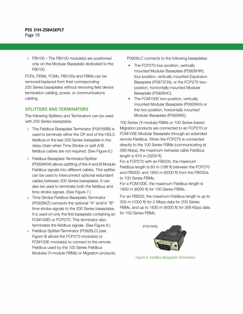
The Fieldbus Baseplate Terminator (P0916RB) is used to terminate either the CP end of the HDLC fieldbus or the last 200 Series baseplate in the daisy chain when Time Strobe or split A/B fieldbus cables are not required. (See Figure 6.)
Fieldbus Baseplate Terminator/Splitter (P0926KW) allows splitting of the A and B Module Fieldbus signals into different cables. This splitter can be used to interconnect optional redundant cables between 200 Series baseplates. It can also be used to terminate both the fieldbus and time strobe signals. (See Figure 7.)
Time Strobe Fieldbus Baseplate Terminator (P0926KZ) connects the optional “A” and/or “B” time strobe signals to the 200 Series baseplates. It is used on only the first baseplate containing an FCM100Et or FCP270. This terminator also terminates the fieldbus signals. (See Figure 8.)
Fieldbus Splitter/Terminator (P0926LC) (see Figure 9) allows the FCP270 module(s) or FCM100E module(s) to connect to the remote Fieldbus used by the 100 Series Fieldbus Modules (Y-module FBMs) or Migration products.
P0926LC connects to the following baseplates:
• The FCP270 two-position, vertically mounted Modular Baseplate (P0926HW), four-position, vertically mounted Expansion Baseplate (P0973CN), or the FCP270 two-position, horizontally mounted Modular Baseplate (P0926HC).
• The FCM100E two-position, vertically mounted Modular Baseplate (P0926KH) or the two-position, horizontally mounted Modular Baseplate (P0926KE).
100 Series (Y-module) FBMs or 100 Series-based Migration products are connected to an FCP270 or FCM100E Modular Baseplate through an extended remote Fieldbus. When the FCP270 is connected directly to the 100 Series FBMs (communicating at 268 Kbps), the maximum twinaxial cable Fieldbus length is 915 m (3200 ft).For a FCP270 with an FBI200, the maximum Fieldbus length is 60 m (198 ft) between the FCP270 and FBI200, and 1850 m (6000 ft) from the FBI200s to 100 Series FBMs.For a FCM100E, the maximum Fieldbus length is 1830 m (6000 ft) for 100 Series FBMs.
For an FBI200, the maximum Fieldbus length is up to 305 m (1000 ft) for 2 Mbps data for 200 Series FBMs, and up to 1830 m (6000 ft) for 268 Kbps data for 100 Series FBMs.
Figure 6. Fieldbus Baseplate Terminator
(P0916RB)

PSS 31H-2SBASEPLTPage 11
Figure 7. Fieldbus Baseplate Terminator/Splitter
Figure 8. Time Strobe Fieldbus Baseplate Terminators
Figure 9. Extended Fieldbus Splitter/Terminator
ADDING ADDITIONAL FBM-SUPPORTING 200 SERIES BASEPLATES
You can add additional FBM-supporting 200 Series baseplates to existing FBM-supporting 200 Series baseplates without removing the system from service. To add these baseplates while the system is operational requires that the system have redundant (A and B) buses. A/B Module Fieldbus and Time Strobe splitter/terminators are used to split the A/B Module Fieldbus (2 Mbps) allowing redundant baseplate-to-baseplate cabling as well as the addition of 200 Series baseplates without interrupting bus communication.
(P0926KW)
(P0926KZ)
(P0926LC)

PSS 31H-2SBASEPLTPage 12
FUNCTIONAL SPECIFICATIONS
Power Requirements
INPUT VOLTAGE RANGE (REDUNDANT)
24 V dc +5%, -10%POWER CABLING
Cable Lengths0.4 m (16 in) up to 2.1 m (7 ft)
Regulatory Compliance
ELECTROMAGNETIC COMPATIBILITY (EMC)
European EMC Directive 89/336/EECMeets: EN 50081-2 Emission standard EN 50082-2 Immunity standard EN 61326 Annex A
(Industrial environment)CISPR 11, Industrial Scientific and Medical (ISM) Radio-frequency Equipment - Electromagnetic Disturbance Characteristics - Limits and Methods of Measurement Meets: Class A LimitsIEC 61000-4-2 ESD ImmunityContact ±4 kV, air ±8 kVIEC 61000-4-3 Radiated Field Immunity10 V/m at 80 to 1000 MHzIEC 61000-4-4 Electrical Fast Transient/Burst Immunity±2 kV on I/O, dc power and communication linesIEC 61000-4-5 Surge Immunity±2 kV on ac and dc power lines; ±1 kV on I/O and communications linesIEC 61000-4-6 Immunity to Conducted Disturbances Induced by Radio-frequency Fields3 V (rms) at 150 kHz to 80 MHz on I/O, dc power and communication linesIEC 61000-4-8 Power Frequency Magnetic Field Immunity30 A/m at 50 and 60 Hz
Regulatory Compliance (Cont.)
PRODUCT SAFETY
Underwriters Laboratories (UL) for U.S. and CanadaUL/UL-C listed as suitable for use in Class I, Groups A-D; Division 2; temperature code T4 enclosure based systems. Communications circuits also meet the requirements for Class 2 as defined in Article 725 of the National Electrical Code (NFPA No.70) and Section 16 of the Canadian Electrical Code (CSA C22.1). Conditions for use are as specified in the Standard and Compact 200 Series Subsystem User’s Guide (B0400FA).ATEX (DEMKO) Ex nA IIC T4 Gc certified when connected as described in the Standard and Compact 200 Series Subsystem User’s Guide (B0400FA). For use in an enclosure suited for an ATEX Zone 2 classified area.Marine CertificationBureau Veritas Marine Certification for Environmental Category EC11.

PSS 31H-2SBASEPLTPage 13
ENVIRONMENTAL SPECIFICATIONS(1)
Operating
TEMPERATURE
-20 to +70°C (-4 to +158°F)RELATIVE HUMIDITY
5 to 95% (noncondensing)ALTITUDE
-300 to +3,000 m (-1,000 to +10,000 ft)
Storage
TEMPERATURE
-40 to +70°C (-40 to +158°F)RELATIVE HUMIDITY
5 to 95% (noncondensing)ALTITUDE
-300 to +12,000 m (-1,000 to +40,000 ft)
Contamination (Non-Enclosure Mounted)Class G3 (Harsh) as defined in ISA Standard S71.04
Contamination (Enclosure Mounted)Class G3 (Harsh) as defined in ISA Standard S71.04. Pollution degree 2 as defined in IEC 664-1.
PHYSICAL SPECIFICATIONS
Mounting
DIN RAIL
200 Series baseplates mount on a non-isolated, mechanically supported horizontal or vertical DIN rail, which can be internal to, or external to an enclosure. The 200 Series baseplate attaches to the DIN rail by means of fasteners.RACK MOUNT
A mounting kit (P0930AS) is available for horizontal mounting of the 200 Series baseplate in a standard, 483 mm (19-inch) rack. This kit provides a 25.4 mm (1 inch) mounting depth.
Size(2)
See Figure 10 and Figure 11
Mass (Without Modules)Maximum 0.91 kg (2.0 lb) for 8-position Modular Baseplate.
Rack Mounting BracketMaterial: Steel, Cold-Rolled, 0.0598 mm (16 Gauge)
Construction
MATERIAL
PC and ABS, inflammability UL94 V0DIN RAIL FASTENER
Number fasteners depends on 200 Series baseplate sizeCOLOR
Black
Module Fieldbus Cabling
CABLE LENGTHS
0.125 m (5 in) up to 60 m (198 ft)OVERALL CABLE LENGTH
60 m (198 ft) total allowable cable length
(1) The environmental limits of the 200 Series baseplates may be enhanced by the type of enclosure containing the 200 Series baseplate.[Refer to the applicable Product Specification Sheet (PSS) which describes the specific type of enclosure that is to be used.(2) For dimensions of the FCP270, refer to PSS 21H-1B9.

PSS 31H-2SBASEPLTPage 14
Figure 10. Dimensions - Vertical Mounted 200 Series Baseplates
120.34.74
2-POSITION
240.09.10
4-POSITIONmmin
453.017.83
216.0
8.5
252.4
9.9
8-POSITION
7.5.30
27.11.07
97.73.8
1807.08
30.31.19
753.0
TOP VIEW CableClearance
VERTICAL MODULAR BASEPLATES
Total MinimumClearance
NOTE: Clearance dimensions shown for 200 Series Fieldbus Modules installed in baseplates. For the clearance dimensions required for larger modules such as the FCP270, refer to the Product Specification Sheet associated with these larger modules. Cable clearance is the same for both 200 Series FBMs and other modules, such as the FCP270.
[ ]
Baseplate-Mounted Termination Assembly Shown Mounted on Baseplate (Optional) - Increases baseplates’s Width, if Installed
PSS 31H-2SBASEPLTPage 15
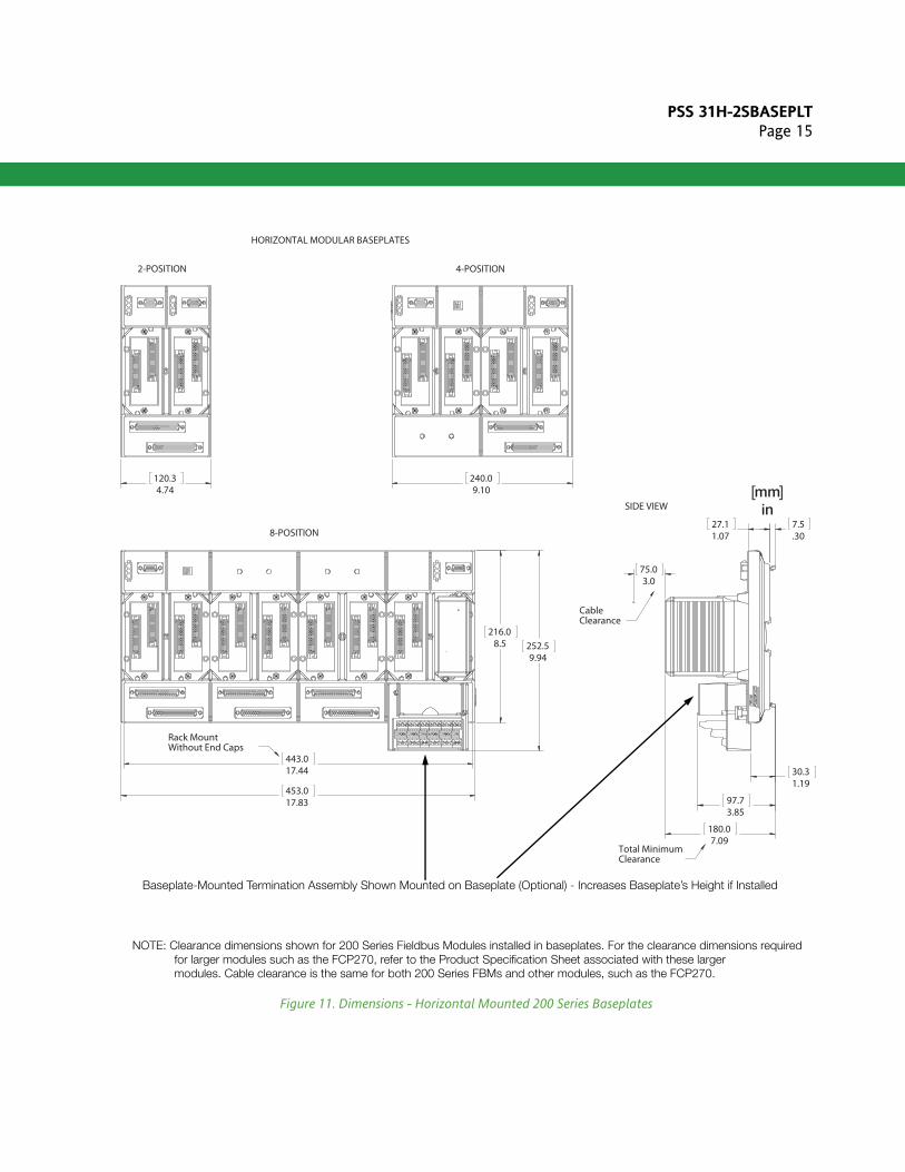
Figure 11. Dimensions - Horizontal Mounted 200 Series Baseplates
120.34.74
2-POSITION
240.09.10
4-POSITION
252.59.94
453.017.83
443.017.44
216.08.5
8-POSITION
Rack Mount Without End Caps
30.31.19
180.07.09
97.73.85
7.5.30
27.11.07
75.03.0
Total MinimumClearance
CableClearance
SIDE VIEWmmin
HORIZONTAL MODULAR BASEPLATES
Baseplate-Mounted Termination Assembly Shown Mounted on Baseplate (Optional) - Increases Baseplate’s Height if Installed
NOTE: Clearance dimensions shown for 200 Series Fieldbus Modules installed in baseplates. For the clearance dimensions required for larger modules such as the FCP270, refer to the Product Specification Sheet associated with these larger modules. Cable clearance is the same for both 200 Series FBMs and other modules, such as the FCP270.
[ ]

PSS 31H-2SBASEPLTPage 16
Invensys Systems, Inc10900 Equity DriveHouston, TX 77041United States of Americahttp://www.invensys.com
Global Customer SupportInside U.S.: 1-866-746-6477Outside U.S.: 1-508-549-2424 Website: http://support.ips.invensys.com
Copyright 2014–2015 Invensys Systems, Inc.All rights reserved. Invensys is now part of Schneider Electric.
Schneider Electric, Invensys, I/A Series, Foxboro, and Foxboro Evo are trademarks owned by Schneider Electric SE, its subsidiaries and affiliates.All other trademarks are the property of their respectiveowners. MB 031 0415

![[PSS 21S-10B11 B3] Wonderware Historian - Infi 90 Infi90 Documentation/FoxIA...PSS 21S-10B11 B3 Page 5 The Configuration Editor enables most of the Wonderware Historian configuration](https://img.pdfslide.us/doc/110x75/5e575295d2292c3a996f9b00/pss-21s-10b11-b3-wonderware-historian-infi-90-infi90-documentationfoxia.jpg)

![[PSS 21H-7R4B3] DCS Integrator for Honeywell Systems Infi90 Documentation/FoxIA/21h7r4b3.pdfDCS Integrator for Honeywell ... operator display, history, alarming, and control. PSS 21H-7R4](https://img.pdfslide.us/doc/110x75/5eb546bd8ae69c66e958caa1/pss-21h-7r4b3-dcs-integrator-for-honeywell-infi90-documentationfoxia21h7r4b3pdf.jpg)

![[PSS 21H-2X2B4] DIN Rail Mounted Fieldbus Module Baseplate Infi90 Documentation... · PSS 21H-2X2 B4 Page 5 MODULE PLACEMENT AND REMOVAL The following rules must be observed with](https://img.pdfslide.us/doc/110x75/5f74d6f1f28e9e6f3c15f5d9/pss-21h-2x2b4-din-rail-mounted-fieldbus-module-infi90-documentation-pss-21h-2x2.jpg)


![[PSS 21H-2Y12B4] Intrinsically Safe Termination Assembly ... Infi90 Documentation/FoxIA/21h2y12b4.… · baseplate. TERMINATION The baseplate consist of 9-pin sub-D-connectors for](https://img.pdfslide.us/doc/110x75/5ea6c3a364ef4c2eb01e83f5/pss-21h-2y12b4-intrinsically-safe-termination-assembly-infi90-documentationfoxia21h2y12b4.jpg)


![[PSS 21S-10G4 B3] Substation Automation Configuration for ... Infi90 Documentation/FoxIA/21s10g4b3.pdfThe function to generate the ICD, CID and SCD files, which captures all configured](https://img.pdfslide.us/doc/110x75/5ea91e629da39d365b5f0212/pss-21s-10g4-b3-substation-automation-configuration-for-infi90-documentationfoxia21s10g4b3pdfthe.jpg)