Embed Size (px)
Citation preview

PSS 21H-2Z1 B5
I/A Series® HARDWAREProduct Specifications
FBM201e Analog Input (0 to 20 mA) Interface Modules
The FBM201e Analog Input Interface Module provides eight dc current input channels.
FEATURES
Key features of the FBM201e module are:
Eight 0 to 20 mA dc channels for input of analog sensor signals
Each analog input channel is galvanically isolated from other channels and ground
Compact, rugged design suitable for enclosure in Class G3 (harsh) environments
Execution of an analog input application program that provides conversion time and configurable options for integration time and Rate of Change Limits
High accuracy achieved by sigma-delta data conversions for each channel
Termination Assemblies (TAs) for locally or remotely connecting field wiring to the FBM201e
Termination Assemblies for per channel internally and/or externally loop powered transmitters.
OVERVIEW
Each FBM201e Analog Input Interface Module contains eight analog input channels, each channel accepting a 2-wire, dc input from an analog sensor such as a 4 to 20 mA transmitter.

PSS 21H-2Z1 B5Page 2
The modules perform the signal conversion required to interface the electrical input signals from the field sensors to the optionally redundant fieldbus.
COMPACT DESIGN
The FBM201e module has a compact design, with a rugged extruded aluminum exterior for physical protection of the circuits. Enclosures specially designed for mounting the FBMs provide various levels of environmental protection, up to harsh environments per ISA Standard S71.04.
HIGH ACCURACY
For high accuracy, the module incorporates sigma-delta data conversion on a per-channel basis, which can provide a new analog input reading every 25 ms, and a configurable integration period to remove any process noise and power-line frequency noise.
Each time period, the FBM converts each analog input to a digital value, averages these values over the time period, and provides the averaged value to the controller.
EASY REMOVAL/REPLACEMENT
The module can be removed/replaced without removing field device termination cabling, power or communications cabling.
VISUAL INDICATORS
Light-emitting diodes (LEDs) incorporated into the front of the modules provide visual status indications of Fieldbus Module (FBM) functions.
MODULAR BASEPLATE MOUNTING
The module mounts on a modular baseplate (see Figure 1) which accommodates up to four or eight FBMs. The modular baseplate is either DIN rail mounted or rack mounted, and includes signal connectors for redundant fieldbus, redundant independent dc power, and termination cables.
FIELDBUS COMMUNICATION
A Fieldbus Communication Module or a Control Processor interfaces the redundant 2 Mbps module Fieldbus used by the FBMs. The FBM201e module accepts communication from either path (A or B) of the redundant 2 Mbps fieldbus – should one path fail or be disabled at the system level, the module continues communication over the active path.
TERMINATION ASSEMBLIES
Field I/O signals connect to the FBM subsystem via DIN rail mounted TAs (see Figure 1). The TAs used with the FBM201e module are described in “TERMINATION ASSEMBLIES AND CABLES” on page 7.

PSS 21H-2Z1 B5Page 3
Figure 1. FBM201e Subsystem – Typical
Termination FBM201eAssembly (P0924TA)
TerminationCable
FBMBaseplate
FieldbusCables

PSS 21H-2Z1 B5Page 4
FUNCTIONAL SPECIFICATIONS
Process I/O CommunicationsCommunicates with its associated FCM or FCP via the redundant 2 Mbps module Fieldbus.
Input Channels8 isolated and independent channels
Input Range (each channel)0 to 20 mA dc
Input Channels (8)
ANALOG ACCURACY (INCLUDES LINEARITY)
±0.02% of spanAccuracy temperature coefficient: ±50 ppm/ºCFIELD DEVICE CABLING DISTANCE
Maximum distance of the field device from the FBM is a function of compliance voltage @20 mA (21.4 V dc), wire resistance, and voltage drop at the field device.INPUT CHANNEL IMPEDANCE
61.5 Ω nominalINPUT SIGNAL A/D CONVERSION
Each channel performs A/D signal conversion using an independent Sigma-Delta converter.INTEGRATION PERIOD
Software configurable.COMMON MODE REJECTION
>100 db at 50 or 60 HzNORMAL MODE REJECTION
>95 db at 50 or 60 HzLOOP SUPPLY
24 V dc ±2.5%OUTPUT IMPEDANCE
68 ΩLOOP POWER SUPPLY PROTECTION
Each channel is channel-to-channel galvanically isolated, current limited, and voltage regulated. All analog inputs are limited by their design to less than 30 mA. If the current limit circuit shorted out, the current is limited to about 100mA.
Input Channel IsolationEach channel is galvanically isolated from all other channels and earth (ground). The module/TA withstands, without damage, a potential of 600 V ac applied for one minute between any channel and ground, or between a given channel and any other channel.
WARNING
This does not imply that these channels are intended for permanent connection to voltages of these levels. Exceeding the limits for input voltages, as stated elsewhere in this specification, violates electrical safety codes and may expose users to electric shock.
Power Requirements
INPUT VOLTAGE RANGE (REDUNDANT)
24 V dc +5%, -10%CONSUMPTION
7 W (maximum)HEAT DISSIPATION
3 W (maximum)
Calibration RequirementsCalibration of the module and termination assembly is not required.

PSS 21H-2Z1 B5Page 5
FUNCTIONAL SPECIFICATIONS (CONTINUED)
Regulatory Compliance
ELECTROMAGNETIC COMPATIBILITY (EMC)
European EMC Directive 89/336/EECMeets: EN 50081-2 Emission standard EN 50082-2 Immunity standard EN 61326 Annex A (Industrial Levels)CISPR 11, Industrial Scientific and Medical (ISM) Radio-frequency Equipment - Electromagnetic Disturbance Characteristics - Limits and Methods of MeasurementMeets Class A LimitsIEC 61000-4-2 ESD ImmunityContact 4 kV, air 8 kVIEC 61000-4-3 Radiated Field Immunity10 V/m at 80 to 1000 MHzIEC 61000-4-4 Electrical Fast Transient/Burst Immunity2 kV on I/O, dc power and communication linesIEC 61000-4-5 Surge Immunity2kV on ac and dc power lines; 1kV on I/O and communications linesIEC 61000-4-6 Immunity to Conducted Disturbances Induced by Radio frequency Fields10 V (rms) at 150 kHz to 80 MHz on I/O, dc power and communication linesIEC 61000-4-8 Power Frequency Magnetic Field Immunity30 A/m at 50 and 60 Hz
PRODUCT SAFETY
Underwriters Laboratories (UL) for U.S. and CanadaUL/UL-C listed as suitable for use inUL/UL-C listed Class I, Groups A-D; Division 2; temperature code T4 enclosure based systems. These modules are also UL and UL-C listed as associated apparatus for supplying non-incendive communication circuits for Class I, Groups A-D hazardous locations when connected to specified I/A Series® processor modules as described in the I/A Series DIN Rail Mounted Subsystem User’s Guide (B0400FA). Communications circuits also meet the requirements for Class 2 as defined in Article 725 of the National Electrical Code (NFPA No.70) and Section 16 of the Canadian Electrical Code (CSA C22.1). Conditions for use are as specified in the I/A Series DIN Rail Mounted Subsystem User’s Guide (B0400FA).European Low Voltage Directive 73/23/EEC and Explosive Atmospheres (ATEX) directive 94/9/ECCENELEC (DEMKO) certified as EEx nA [nL] IIC T4 for use in CENELEC certified Zone 2 enclosure certified as associated apparatus for supplying non-incendive field circuits for Zone 2, Group IIC, potentially explosive atmospheres when connected to specified I/A Series processor modules as described in the I/A Series DIN Rail Mounted Subsystem User’s Guide (B0400FA). Also, see Table 1 on page 8.

PSS 21H-2Z1 B5Page 6
ENVIRONMENTAL SPECIFICATIONS(1)
Operating
TEMPERATURE
FBM201e-20 to +70°C (-4 to +158°F)Termination Assembly-20 to +70°C (-4 to +158°F)
RELATIVE HUMIDITY
5 to 95% (noncondensing)ALTITUDE
-300 to +3,000 m (-1,000 to +10,000 ft)
Storage
TEMPERATURE
-40 to +70°C (-40 to +158°F)
RELATIVE HUMIDITY
5 to 95% (noncondensing).ALTITUDE
-300 to +12,000 m (-1,000 to +40,000 ft)
ContaminationSuitable for use in Class G3 (Harsh) environments as defined in ISA Standard S71.04, based on exposure testing according to EIA Standard 364-65, Class III.
Vibration7.5 m/S2 (0.75 g) from 5 to 500 Hz
PHYSICAL SPECIFICATIONS
Mounting
FBM201e
The module mounts on a modular baseplate. The baseplate can be mounted on a DIN rail (horizontally or vertically), or horizontally on a19-inch rack using a mounting kit. Refer to DIN Rail Mounted Modular Baseplates (PSS 21H-2W6 B4) for details.TERMINATION ASSEMBLY
The TA mounts on a DIN rail and accommodates multiple DIN rail styles including 32 mm (1.26 in) and 35 mm 1.38 in).
Mass
FBM201e
284 g (10 oz) approximateTERMINATION ASSEMBLY
Compression181 g (0.40 lb) approximateRing Lug249 g (0.55 lb) approximate
Dimensions – FBM201e
HEIGHT
102 mm (4 in)114 mm (4.5 in) with mounting lugsWIDTH
45 mm (1.75 in)DEPTH
104 mm (4.11 in)
Dimensions – Termination AssemblySee page 10
Part Number
FBM201e
P0924TATERMINATION ASSEMBLIES
See “FUNCTIONAL SPECIFICATIONS – TERMINATION ASSEMBLIES” on page 8
(1) The environmental limits of this module may be enhanced by the type of enclosure containing the module. Refer to the applicable Product Specification Sheet (PSS) which describes the specific type of enclosure that is to be used.

PSS 21H-2Z1 B5Page 7
PHYSICAL SPECIFICATIONS (CONTINUED)
Termination Cables
CABLE LENGTHS
Up to 30 m (98 ft)CABLE MATERIALS
Hypalon®/XLPTERMINATION CABLE TYPE
Type 1 – See Table 2 on page 9BASEPLATE TO MAIN TA CABLE CONNECTION
FBM Baseplate End37-pin D-subminiatureTermination Assembly End25-pin D-subminiature
Construction – Termination Assembly
MATERIAL
Polyamide (PA), compressionPA, ring lug
Field Termination Connections
COMPRESSION-TYPE ACCEPTED WIRING
SIZES
Solid/Stranded/AWG0.2 to 4 mm2/0.2 to 2.5 mm2/24 to 12 AWGStranded with Ferrules0.2 to 2.5 mm2 with or without plastic collar
RING-LUG TYPE ACCEPTED WIRING SIZES
#6 size connectors (0.375 in (9.5 mm))0.5 to 4 mm2/22 AWG to 12 AWG
TERMINATION ASSEMBLIES AND CABLES
Field input signals connect to the FBM subsystem via DIN rail mounted Termination Assemblies, which are electrically passive (see Figure 1). TAs for the FBM201e module are available in the following forms:
Compression screw type using Polyamide (PA) material
Ring lug type using Polyamide (PA) material
See “FUNCTIONAL SPECIFICATIONS – TERMINATION ASSEMBLIES” on page 8 for a list of TAs used with the FBM201e module.
A removable termination cable connects the DIN rail mounted TA to the FBM via a field connector on the baseplate in which the FBM is installed. Termination cables are available in Hypalon® XLP.
Termination cables are available in a variety of lengths, up to 30 meters (98 feet), allowing the Termination Assembly to be mounted in either the enclosure or in an adjacent enclosure. See Table 2 for a list of termination cables used with the TAs for the FBM201e module.
PSS 21H-2Z1 B5Page 8
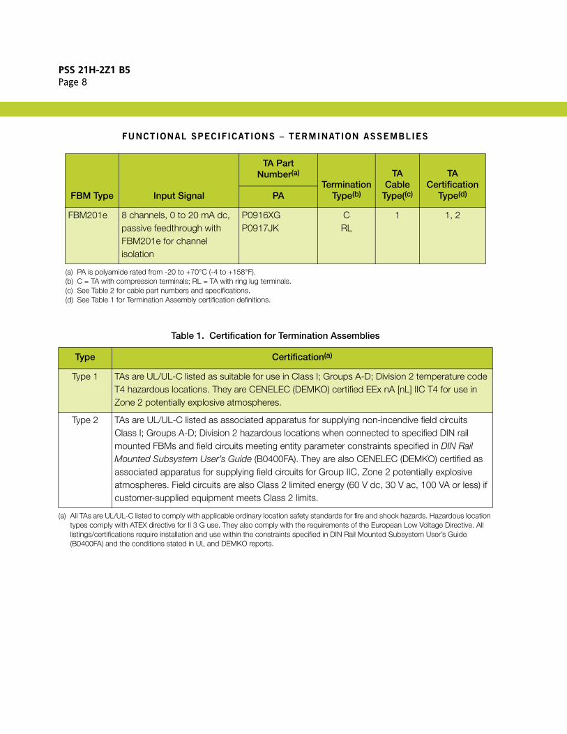
FUNCTIONAL SPECIFICATIONS – TERMINATION ASSEMBLIES
FBM Type Input Signal
TA Part Number(a)
(a) PA is polyamide rated from -20 to +70°C (-4 to +158°F).
TerminationType(b)
(b) C = TA with compression terminals; RL = TA with ring lug terminals.
TA Cable
Type((c)
(c) See Table 2 for cable part numbers and specifications.
TACertification
Type(d)
(d) See Table 1 for Termination Assembly certification definitions.
PA
FBM201e 8 channels, 0 to 20 mA dc, passive feedthrough with FBM201e for channel isolation
P0916XGP0917JK
CRL
1 1, 2
Table 1. Certification for Termination Assemblies
Type Certification(a)
(a) All TAs are UL/UL-C listed to comply with applicable ordinary location safety standards for fire and shock hazards. Hazardous location types comply with ATEX directive for II 3 G use. They also comply with the requirements of the European Low Voltage Directive. All listings/certifications require installation and use within the constraints specified in DIN Rail Mounted Subsystem User’s Guide (B0400FA) and the conditions stated in UL and DEMKO reports.
Type 1 TAs are UL/UL-C listed as suitable for use in Class I; Groups A-D; Division 2 temperature code T4 hazardous locations. They are CENELEC (DEMKO) certified EEx nA [nL] IIC T4 for use in Zone 2 potentially explosive atmospheres.
Type 2 TAs are UL/UL-C listed as associated apparatus for supplying non-incendive field circuits Class I; Groups A-D; Division 2 hazardous locations when connected to specified DIN rail mounted FBMs and field circuits meeting entity parameter constraints specified in DIN Rail Mounted Subsystem User’s Guide (B0400FA). They are also CENELEC (DEMKO) certified as associated apparatus for supplying field circuits for Group IIC, Zone 2 potentially explosive atmospheres. Field circuits are also Class 2 limited energy (60 V dc, 30 V ac, 100 VA or less) if customer-supplied equipment meets Class 2 limits.

PSS 21H-2Z1 B5Page 9
Table 2. Cables Types and Part Numbers
Cable Lengthm (ft)
Type 1H/XLPE(a)
0.5 (1.6) P0916VA
1.0 (3.2) P0916VB
2.0 (6.6) P0931RR
3.0 (9.8) P0916VC
5.0 (16.4) P0916VD
10.0 (32.8) P0916VE
15.0 (49.2) P0916VF
20.0 (65.6) P0916VG
25.0 (82.0) P0916VH
30.0 (98.4) P0916VJ
(a) H/XLPE is Hypalon outer jacket and XLPE (cross-linked polyethylene) primary conductor insulation.

PSS 21H-2Z1 B5Page 10
DIMENSIONS – NOMINAL
[125]4.93
[76] (a)2.99
[80]3.13
[72] (b)2.83
[111] (a)4.37
[125]4.93
[80]3.13
[72] (b)2.83
Compression TA: P0916XG
Ring Lug TA: P0917JK
(a) Overall width – for determining DIN rail loading.(b) Height above DIN rail (add to DIN rail height for total).

PSS 21H-2Z1 B5Page 11
RELATED PRODUCT SPECIFICATION SHEETS (PSS)
PSS Number Description
PSS 21H-2W1 B3 DIN Rail Mounted FBM Subsystem Overview
PSS 21H-2W2 B3 DIN Rail Mounted FBM Equipment, Agency Certification
PSS 21H-2W6 B4 DIN Rail Mounted Modular Baseplates
PSS 21S-3B2 B3 Control Processor 270 (CP270) Integrated Control Software

PSS 21H-2Z1 B5Page 12
Invensys Operations Management5601 Granite Parkway Suite 1000Plano, TX 75024United States of Americahttp://iom.invensys.com
Global Customer SupportInside U.S.: 1-866-746-6477Outside U.S.: 1-508-549-2424 or contact your local Invensys representative.Email: [email protected]: http://support.ips.invensys.com
Invensys, Foxboro, I/A Series, and the Invensys logo are trademarks of Invensys plc, its subsidiaries, and affiliates.All other brands and product names may be the trademarks of their respective owners.
Copyright 2010 Invensys Systems, Inc. All rights reserved. Unauthorized duplication or distribution is strictly prohibited.
MB 21A 0410