Embed Size (px)
Citation preview
Foxboro Evo™ Process Automation System
Product Specifications
PSS 31H-2Z41
FBM241/b/c/d Discrete I/O Modules
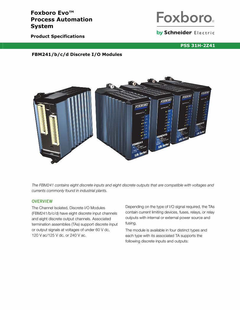
The FBM241 contains eight discrete inputs and eight discrete outputs that are compatible with voltages and currents commonly found in industrial plants.
OVERVIEW
The Channel Isolated, Discrete I/O Modules (FBM241/b/c/d) have eight discrete input channels and eight discrete output channels. Associated termination assemblies (TAs) support discrete input or output signals at voltages of under 60 V dc, 120 V ac/125 V dc, or 240 V ac.
Depending on the type of I/O signal required, the TAs contain current limiting devices, fuses, relays, or relay outputs with internal or external power source and fusing.
The module is available in four distinct types and each type with its associated TA supports the following discrete inputs and outputs:
PSS 31H-2Z41Page 2
Each type of FBM, without signal conditioning, uses a 15 to 60 V dc input or output signal. Each discrete input and output is galvanically isolated from other channels and ground. When used with external excitation, each discrete input and output is group isolated.
The module performs signal conversion required to interface electrical input signals from field sensors to the optionally redundant Fieldbus. It executes the Discrete I/O or Ladder Logic program, with the following configurable options: Input Filter Time, Fail Safe Configuration, Fail-Safe Fall-Back, and Sustained or Momentary Outputs. If the Momentary Output configuration is selected, then Pulse Output Interval is also configurable.
FEATURES
Key features of the FBM241/b/c/d modules are:
Eight discrete inputs
Eight discrete outputs
Supports discrete inputs/output signals at voltages of:
• 15 to 60 V dc• 120 V ac/125 V dc• 240 V ac
Each input and output is galvanically isolated: group isolated when used with external excitation
Compact, rugged design suitable for enclosure in Class G3 (harsh) environments
Executes the Discrete I/O or Ladder Logic program, with the following configurable options: Input Filter Time, Fail Safe Configuration, Fail-Safe Fall-Back, and Sustained or Momentary Outputs
Various Termination Assemblies (TAs) that contain:• Current limiting devices• Fuses• Relay outputs • Relay outputs with internal or external power
source and fusing• Solid state outputs.
COMPACT DESIGN
The module has a compact design, with a rugged extruded aluminum exterior for physical protection of the circuits. Enclosures specially designed for mounting the FBMs provide various levels of environmental protection, up to harsh environments, per ISA Standard S71.04.
FBM Inputs Outputs
FBM241 15 to 60 V dc, 125 V dc, 120 V ac, or 240 V ac Switch (external or internal power source)
15 to 60 V dc at 2 A, or 30 V dc at 5 A, or 125 V dc at 0.5 A, or 120 V ac at 5 A, or 240 V ac at 5 A Switch (external or internal power source)
FBM241b 15 to 60 V dc Switch
12 V dc at 12 mA Switch (internal power source)
FBM241c 15 to 60 V dc Contact (unprotected -no fuse, or protected - fused)
15 to 60 V dc at 2 A, or 240 V ac at 5 A Switch (external or internal power source)
FBM241d 15 to 60 V dc Contact
12 V dc at 12 mA Switch (internal power source)
PSS 31H-2Z41Page 3
VISUAL INDICATORS
Light-emitting diodes (LEDs) incorporated into the front of the module provide visual indication of the Fieldbus Module operational status, as well as the discrete states of the individual input and output points.
EASY REMOVAL/REPLACEMENT
The module can be removed/replaced without removing field device termination cabling, power, or communication cabling.
FIELDBUS COMMUNICATION
A Fieldbus Communications Module or a Control Processor interfaces to the redundant 2 Mbps module Fieldbus used by the FBMs. The FBM241 accepts communication from either path (A or B) of the redundant 2 Mbps Fieldbus - should one path fail or be switched at the system level, the module continues communication over the active path.
MODULAR BASEPLATE MOUNTING
The module mounts on a DIN rail mounted baseplate, which accommodates up to four or eight Fieldbus Modules. The Modular Baseplate is either DIN rail mounted or rack mounted, and includes signal connectors for redundant Module Fieldbus, redundant independent dc power, and termination cables.
SECURITY
Field power for contacts or solid state switches is current limited.
TERMINATION ASSEMBLIES
Field I/O signals connect to the FBM subsystem via DIN rail mounted TAs. The TAs used with the FBM241/b/c/d are described in “5 A at up to 120 V ac (see “GENERAL PURPOSE PLUG-IN RELAY TERMINATION ASSEMBLY SPECIFICATIONS” on page 22)” on page 8.
PSS 31H-2Z41Page 4
FUNCTIONAL SPECIFICATIONS
Input/Output Channels8 input and 8 output isolated channels
Filter/Debounce Time(1)
Configurable (No Filtering, 4, 8, 16, or 32 ms)
Voltage Monitor Function (FBM241 and
FBM241b)
INPUT
On-State Voltage15 to 60 V dcOff-State Voltage0 to 5 V dcCurrent1.4 mA (typical) at 5 to 60 V dc
SOURCE RESISTANCE LIMITS
On-State1 k Ω (maximum) at 15 V dcOff-State100 k Ω (minimum) at 60 V dc
Contact Sensor Function (FBM241c and
FBM241d)
RANGE (EACH CHANNEL)
Contact open (off) or closed (on)OPEN-CIRCUIT VOLTAGE
24 V dc ±15%SHORT-CIRCUIT CURRENT
2.5 mA (maximum)ON-STATE RESISTANCE
1.0 k Ω (maximum)OFF-STATE RESISTANCE
100 k Ω (minimum)
Output Switch with External Source (FBM241
and FBM241c)
APPLIED VOLTAGE
60 V dc (maximum)LOAD CURRENT
2.0 A (maximum)OFF-STATE LEAKAGE CURRENT
0.1 mA (maximum)
Output Switch with Internal Source (FBM241b
and FBM241d)
OUTPUT VOLTAGE (NO LOAD)
12 V dc ±20%SOURCE RESISTANCE
680 Ω (nominal)SHORTED OUTPUT (ON-STATE) DURATION
IndefiniteOFF-STATE LEAKAGE CURRENT
0.1 mA (maximum)
Inductive LoadsOutput may require a protective diode or metal oxide varistor (MOV) connected across the inductive load.
IsolationEach channel is galvanically isolated from all other channels and earth (ground). The module withstands, without damage, a potential of 600 V ac applied for one minute between any channel and ground, or between a given channel and any other channel. Channels are group isolated when used with external excitation.
CAUTION
This does not imply that these channels are intended for permanent connection to voltages of these levels. Exceeding the limits for external voltages, as stated elsewhere in this specification, violates electrical safety codes and may expose users to electric shock.
CommunicationCommunicates with its associated FCM or FCP via the redundant 2 Mbps HDLC module Fieldbus
(1) Digital filtering available for 200 Series FBM or competitive migration modules with version 1.25H or later firmware.
PSS 31H-2Z41Page 5
FUNCTIONAL SPECIFICATIONS (CONTINUED)
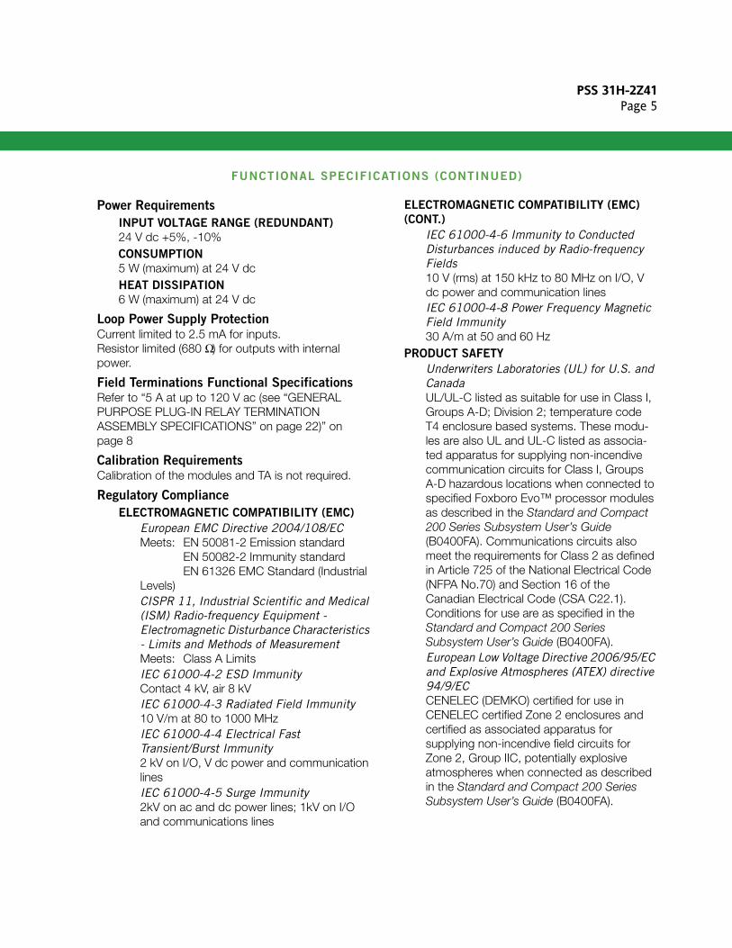
Power Requirements
INPUT VOLTAGE RANGE (REDUNDANT)
24 V dc +5%, -10%CONSUMPTION
5 W (maximum) at 24 V dcHEAT DISSIPATION
6 W (maximum) at 24 V dc
Loop Power Supply ProtectionCurrent limited to 2.5 mA for inputs.Resistor limited (680 Ω) for outputs with internal power.
Field Terminations Functional SpecificationsRefer to “5 A at up to 120 V ac (see “GENERAL PURPOSE PLUG-IN RELAY TERMINATION ASSEMBLY SPECIFICATIONS” on page 22)” on page 8
Calibration RequirementsCalibration of the modules and TA is not required.
Regulatory Compliance
ELECTROMAGNETIC COMPATIBILITY (EMC)
European EMC Directive 2004/108/ECMeets: EN 50081-2 Emission standard EN 50082-2 Immunity standard EN 61326 EMC Standard (Industrial Levels)CISPR 11, Industrial Scientific and Medical (ISM) Radio-frequency Equipment - Electromagnetic Disturbance Characteristics - Limits and Methods of Measurement Meets: Class A LimitsIEC 61000-4-2 ESD ImmunityContact 4 kV, air 8 kVIEC 61000-4-3 Radiated Field Immunity10 V/m at 80 to 1000 MHzIEC 61000-4-4 Electrical Fast Transient/Burst Immunity2 kV on I/O, V dc power and communication linesIEC 61000-4-5 Surge Immunity2kV on ac and dc power lines; 1kV on I/O and communications lines
ELECTROMAGNETIC COMPATIBILITY (EMC)
(CONT.)
IEC 61000-4-6 Immunity to Conducted Disturbances induced by Radio-frequency Fields10 V (rms) at 150 kHz to 80 MHz on I/O, V dc power and communication linesIEC 61000-4-8 Power Frequency Magnetic Field Immunity30 A/m at 50 and 60 Hz
PRODUCT SAFETY
Underwriters Laboratories (UL) for U.S. and CanadaUL/UL-C listed as suitable for use in Class I, Groups A-D; Division 2; temperature code T4 enclosure based systems. These modu-les are also UL and UL-C listed as associa-ted apparatus for supplying non-incendive communication circuits for Class I, Groups A-D hazardous locations when connected to specified Foxboro Evo™ processor modules as described in the Standard and Compact 200 Series Subsystem User’s Guide (B0400FA). Communications circuits also meet the requirements for Class 2 as defined in Article 725 of the National Electrical Code (NFPA No.70) and Section 16 of the Canadian Electrical Code (CSA C22.1). Conditions for use are as specified in the Standard and Compact 200 Series Subsystem User’s Guide (B0400FA).European Low Voltage Directive 2006/95/EC and Explosive Atmospheres (ATEX) directive 94/9/ECCENELEC (DEMKO) certified for use in CENELEC certified Zone 2 enclosures and certified as associated apparatus for supplying non-incendive field circuits for Zone 2, Group IIC, potentially explosive atmospheres when connected as described in the Standard and Compact 200 Series Subsystem User’s Guide (B0400FA).
PSS 31H-2Z41Page 6
FUNCTIONAL SPECIFICATIONS (CONTINUED)
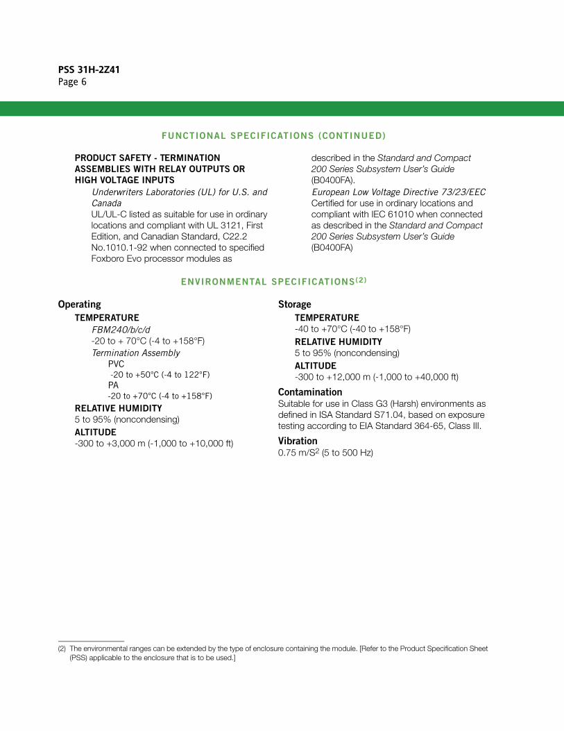
PRODUCT SAFETY - TERMINATION
ASSEMBLIES WITH RELAY OUTPUTS OR
HIGH VOLTAGE INPUTS
Underwriters Laboratories (UL) for U.S. and CanadaUL/UL-C listed as suitable for use in ordinary locations and compliant with UL 3121, First Edition, and Canadian Standard, C22.2 No.1010.1-92 when connected to specified Foxboro Evo processor modules as
described in the Standard and Compact 200 Series Subsystem User’s Guide (B0400FA).European Low Voltage Directive 73/23/EECCertified for use in ordinary locations and compliant with IEC 61010 when connected as described in the Standard and Compact 200 Series Subsystem User’s Guide (B0400FA)
ENVIRONMENTAL SPECIFICATIONS(2)
Operating
TEMPERATURE
FBM240/b/c/d-20 to + 70°C (-4 to +158°F)Termination Assembly
PVC -20 to +50°C (-4 to 122°F)PA-20 to +70°C (-4 to +158°F)
RELATIVE HUMIDITY
5 to 95% (noncondensing)ALTITUDE
-300 to +3,000 m (-1,000 to +10,000 ft)
Storage
TEMPERATURE
-40 to +70°C (-40 to +158°F)RELATIVE HUMIDITY
5 to 95% (noncondensing)ALTITUDE
-300 to +12,000 m (-1,000 to +40,000 ft)
ContaminationSuitable for use in Class G3 (Harsh) environments as defined in ISA Standard S71.04, based on exposure testing according to EIA Standard 364-65, Class III.
Vibration0.75 m/S2 (5 to 500 Hz)
(2) The environmental ranges can be extended by the type of enclosure containing the module. [Refer to the Product Specification Sheet (PSS) applicable to the enclosure that is to be used.]
PSS 31H-2Z41Page 7
PHYSICAL SPECIFICATIONS
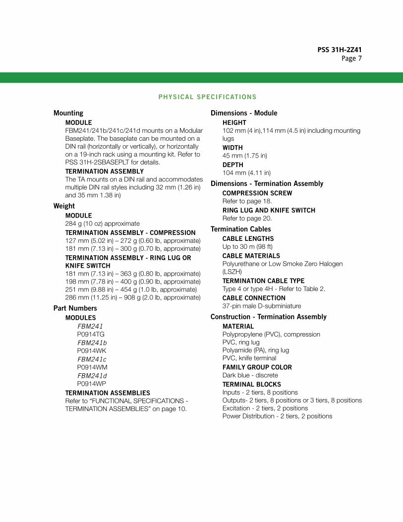
Mounting
MODULE
FBM241/241b/241c/241d mounts on a Modular Baseplate. The baseplate can be mounted on a DIN rail (horizontally or vertically), or horizontally on a 19-inch rack using a mounting kit. Refer to PSS 31H-2SBASEPLT for details.TERMINATION ASSEMBLY
The TA mounts on a DIN rail and accommodates multiple DIN rail styles including 32 mm (1.26 in) and 35 mm 1.38 in)
Weight
MODULE
284 g (10 oz) approximateTERMINATION ASSEMBLY - COMPRESSION
127 mm (5.02 in) – 272 g (0.60 lb, approximate)181 mm (7.13 in) – 300 g (0.70 lb, approximate)TERMINATION ASSEMBLY - RING LUG OR
KNIFE SWITCH
181 mm (7.13 in) – 363 g (0.80 lb, approximate)198 mm (7.78 in) – 400 g (0.90 lb, approximate)251 mm (9.88 in) – 454 g (1.0 lb, approximate)286 mm (11.25 in) – 908 g (2.0 lb, approximate)
Part Numbers
MODULES
FBM241P0914TGFBM241bP0914WKFBM241cP0914WMFBM241dP0914WP
TERMINATION ASSEMBLIES
Refer to “FUNCTIONAL SPECIFICATIONS - TERMINATION ASSEMBLIES” on page 10.
Dimensions - Module
HEIGHT
102 mm (4 in),114 mm (4.5 in) including mounting lugsWIDTH
45 mm (1.75 in)DEPTH
104 mm (4.11 in)
Dimensions - Termination Assembly
COMPRESSION SCREW
Refer to page 18.RING LUG AND KNIFE SWITCH
Refer to page 20.
Termination Cables
CABLE LENGTHS
Up to 30 m (98 ft)CABLE MATERIALS
Polyurethane or Low Smoke Zero Halogen (LSZH)TERMINATION CABLE TYPE
Type 4 or type 4H - Refer to Table 2.CABLE CONNECTION
37-pin male D-subminiature
Construction - Termination Assembly
MATERIAL
Polypropylene (PVC), compressionPVC, ring lugPolyamide (PA), ring lugPVC, knife terminal FAMILY GROUP COLOR
Dark blue - discreteTERMINAL BLOCKS
Inputs - 2 tiers, 8 positionsOutputs- 2 tiers, 8 positions or 3 tiers, 8 positionsExcitation - 2 tiers, 2 positionsPower Distribution - 2 tiers, 2 positions
PSS 31H-2Z41Page 8
PHYSICAL SPECIFICATIONS (CONTINUED)
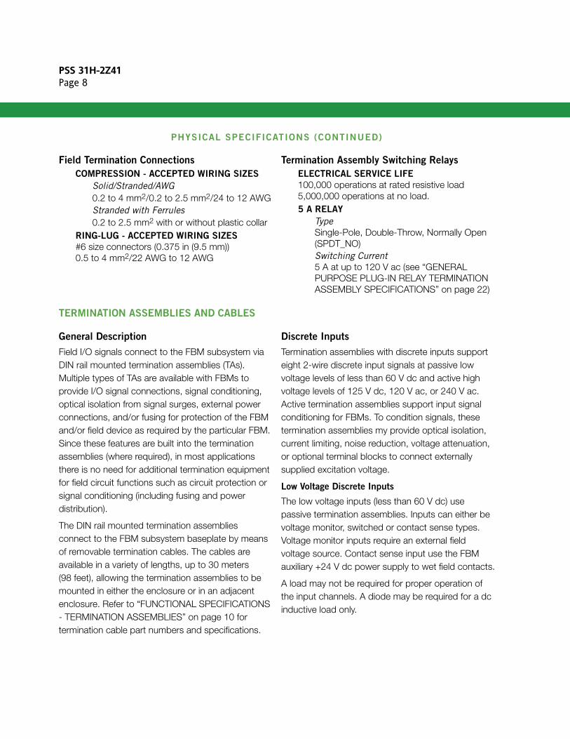
Field Termination Connections
COMPRESSION - ACCEPTED WIRING SIZES
Solid/Stranded/AWG0.2 to 4 mm2/0.2 to 2.5 mm2/24 to 12 AWGStranded with Ferrules0.2 to 2.5 mm2 with or without plastic collar
RING-LUG - ACCEPTED WIRING SIZES
#6 size connectors (0.375 in (9.5 mm))0.5 to 4 mm2/22 AWG to 12 AWG
Termination Assembly Switching Relays
ELECTRICAL SERVICE LIFE
100,000 operations at rated resistive load5,000,000 operations at no load.5 A RELAY
TypeSingle-Pole, Double-Throw, Normally Open (SPDT_NO)Switching Current5 A at up to 120 V ac (see “GENERAL PURPOSE PLUG-IN RELAY TERMINATION ASSEMBLY SPECIFICATIONS” on page 22)
TERMINATION ASSEMBLIES AND CABLES
General Description
Field I/O signals connect to the FBM subsystem via DIN rail mounted termination assemblies (TAs). Multiple types of TAs are available with FBMs to provide I/O signal connections, signal conditioning, optical isolation from signal surges, external power connections, and/or fusing for protection of the FBM and/or field device as required by the particular FBM. Since these features are built into the termination assemblies (where required), in most applications there is no need for additional termination equipment for field circuit functions such as circuit protection or signal conditioning (including fusing and power distribution).
The DIN rail mounted termination assemblies connect to the FBM subsystem baseplate by means of removable termination cables. The cables are available in a variety of lengths, up to 30 meters (98 feet), allowing the termination assemblies to be mounted in either the enclosure or in an adjacent enclosure. Refer to “FUNCTIONAL SPECIFICATIONS - TERMINATION ASSEMBLIES” on page 10 for termination cable part numbers and specifications.
Discrete Inputs
Termination assemblies with discrete inputs support eight 2-wire discrete input signals at passive low voltage levels of less than 60 V dc and active high voltage levels of 125 V dc, 120 V ac, or 240 V ac. Active termination assemblies support input signal conditioning for FBMs. To condition signals, these termination assemblies my provide optical isolation, current limiting, noise reduction, voltage attenuation, or optional terminal blocks to connect externally supplied excitation voltage.
Low Voltage Discrete Inputs
The low voltage inputs (less than 60 V dc) use passive termination assemblies. Inputs can either be voltage monitor, switched or contact sense types. Voltage monitor inputs require an external field voltage source. Contact sense input use the FBM auxiliary +24 V dc power supply to wet field contacts.
A load may not be required for proper operation of the input channels. A diode may be required for a dc inductive load only.
PSS 31H-2Z41Page 9
High Voltage Discrete Inputs
The high voltage input circuits support 125 V dc, 120 V ac, or 240 V ac. Inputs can be either voltage monitor or switched types. Voltage monitor inputs require a field voltage source. Switch inputs use customer supplied excitation voltage applied to dedicated terminals on the termination assembly and distributed on the termination assembly to each of the input channels.
These circuits are located on daughter boards that are mounted under the component covers of the termination assemblies.
Discrete Outputs
Termination assemblies with discrete outputs support eight 2-wire discrete output signals at passive low voltages of less than 60 V dc and active high voltage levels of 120 V ac or 240 V ac. Active termination assemblies support output signal conditioning for FBMs. To condition signals, these termination assemblies provide fuse protection, relays, solid-state devices, and terminal blocks to connect externally supplied optional power distribution.
Low Voltage Discrete Outputs
The low voltage outputs (less than 60 V dc) use passive termination assemblies. These assemblies are available with and without output protection (fusing). Termination assemblies with protection have individual user serviceable fuses that are designed to limit the output current to 2 A. Eight vertically mounted, one per channel, 3.15 A sand filled fuses (temperature derated) allow a maximum of 2 A current per output channel. Termination assemblies without fusing (unprotected) are intended for use by Foxboro® engineers or customers who are using interposing relays or fuse terminal blocks between the termination assembly and the field devices.
Power for the low voltage outputs can be supplied by the FBM +24 V dc auxiliary power supply (internally
(FBM) sourced) or by a field voltage source (externally sourced).
High Voltage Discrete Outputs
The high voltage output (120 V ac or 240 V ac) termination assemblies use plug-in SPDT (Form C) electromechanical relays and solid-state switches. The plug-in sockets allow field replacement of individual relays. The relays and associated sockets are located under the component covers of the termination assemblies.The termination assembly’s switched outputs use unsealed, general purpose relays.These assemblies are capable of providing mixed voltage and are designed to provide signal segregation by locating the low voltage inputs and the opposite side of the terminal assembly from the outputs. A solid-state output module is optionally available. High voltage discrete outputs are always externally sourced power.
The output termination assemblies come in either output or output with power distribution (user-supplied via terminals on the termination assembly). In both configurations, when the FBM output is on, the relay coil is energized and the relay contact is switched from normally closed (NC) position to the normally open (NO) position. The FBM +24 V dc auxiliary power supply is used to energize the relay coil.
Termination assemblies with power distribution have a dedicated terminal block which provides a connection to externally supplied power and distributed internally on the termination assembly to each of the output channels. The line or positive side of the supply is fused; the neutral or negative side of the supply is connected to the field.
The termination assembly has a pair of external excitation voltage terminals, which distribute customer-supplied wetting voltage to all input channels on the assembly. These terminals allow the field power to be daisy chained between terminal assemblies.
PSS 31H-2Z41Page 10
F
F
F
F
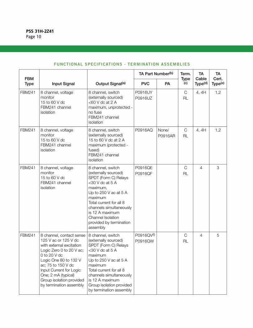
FUNCTIONAL SPECIFICATIONS - TERMINATION ASSEMBLIES
FBM Type Input Signal Output Signal(a)
TA Part Number(b) Term.Type
(c)
TA Cable Type(d)
TA Cert.
Type(e)PVC PA
BM241 8 channel, voltage monitor15 to 60 V dcFBM241 channel isolation
8 channel, switch (externally sourced)<60 V dc at 2 A maximum, unprotected -no fuseFBM241 channel isolation
P0916UYP0916UZ
CRL
4, 4H 1,2
BM241 8 channel, voltage monitor15 to 60 V dcFBM241 channel isolation
8 channel, switch (externally sourced)15 to 60 V dc at 2 A maximum (protected - fused)FBM241 channel isolation
P0916AQ None/P0916AR
CRL
4, 4H 1,2
BM241 8 channel, voltage monitor15 to 60 V dcFBM241 channel isolation
8 channel, switch (externally sourced)SPDT (Form C) Relays<30 V dc at 5 A maximum,Up to 250 V ac at 5 A maximumTotal current for all 8 channels simultaneously is 12 A maximumChannel Isolation provided by termination assembly
P0916QEP0916QF
CRL
4 3
BM241 8 channel, contact sense125 V ac or 125 V dc with external excitationLogic Zero 0 to 20 V ac; 0 to 20 V dcLogic One 80 to 132 V ac; 75 to 150 V dcInput Current for Logic One; 2 mA (typical) Group isolation provided by termination assembly
8 channel, switch (externally sourced)SPDT (Form C) Relays<30 V dc at 5 A maximumUp to 250 V ac at 5 A maximumTotal current for all 8 channels simultaneously is 12 A maximumGroup isolation provided by termination assembly
P0916QV(f)
P0916QWCRL
4 5
PSS 31H-2Z41Page 11
F
F
F
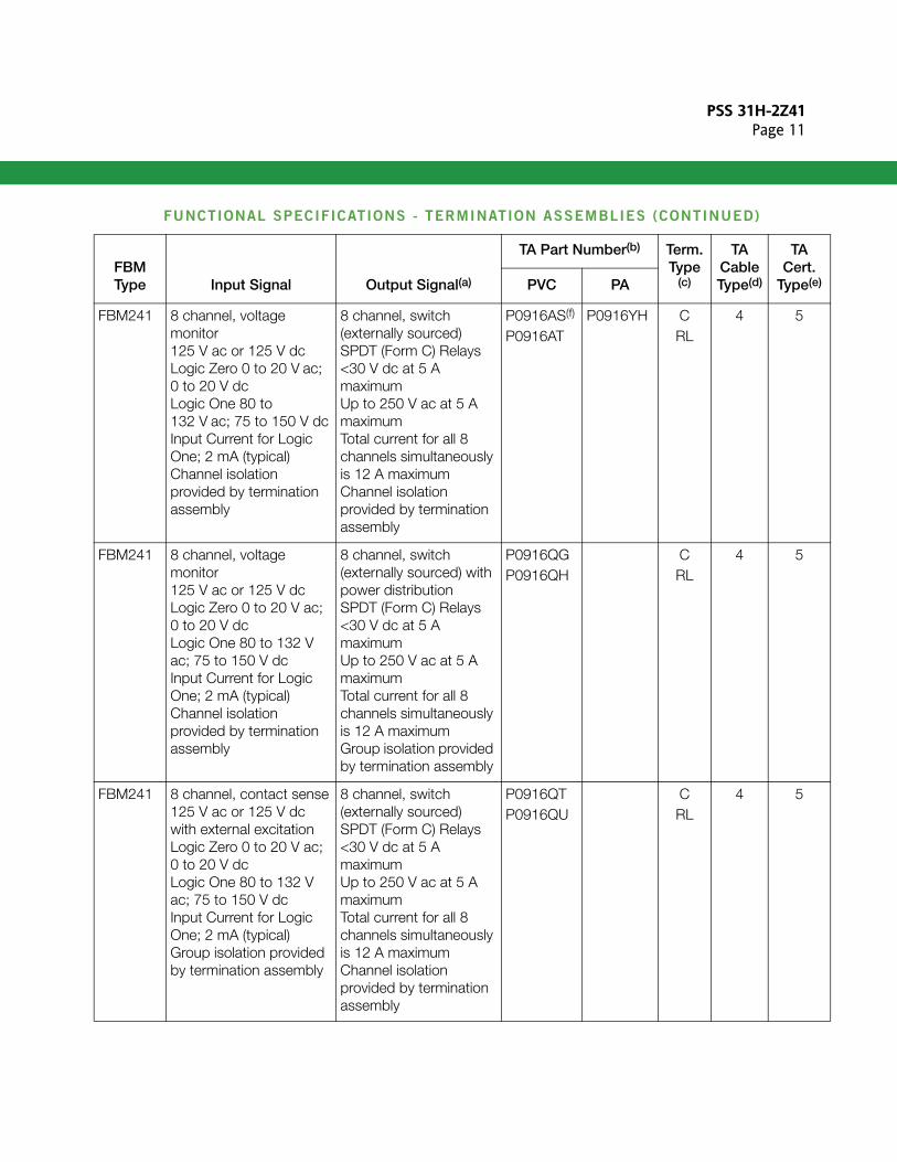
BM241 8 channel, voltage monitor125 V ac or 125 V dcLogic Zero 0 to 20 V ac; 0 to 20 V dcLogic One 80 to 132 V ac; 75 to 150 V dcInput Current for Logic One; 2 mA (typical)Channel isolation provided by termination assembly
8 channel, switch (externally sourced)SPDT (Form C) Relays<30 V dc at 5 A maximumUp to 250 V ac at 5 A maximumTotal current for all 8 channels simultaneously is 12 A maximumChannel isolation provided by termination assembly
P0916AS(f)
P0916ATP0916YH C
RL4 5
BM241 8 channel, voltage monitor125 V ac or 125 V dcLogic Zero 0 to 20 V ac; 0 to 20 V dcLogic One 80 to 132 V ac; 75 to 150 V dcInput Current for Logic One; 2 mA (typical)Channel isolation provided by termination assembly
8 channel, switch (externally sourced) with power distributionSPDT (Form C) Relays<30 V dc at 5 A maximumUp to 250 V ac at 5 A maximumTotal current for all 8 channels simultaneously is 12 A maximumGroup isolation provided by termination assembly
P0916QGP0916QH
CRL
4 5
BM241 8 channel, contact sense125 V ac or 125 V dc with external excitationLogic Zero 0 to 20 V ac; 0 to 20 V dcLogic One 80 to 132 V ac; 75 to 150 V dcInput Current for Logic One; 2 mA (typical)Group isolation provided by termination assembly
8 channel, switch (externally sourced)SPDT (Form C) Relays<30 V dc at 5 A maximumUp to 250 V ac at 5 A maximumTotal current for all 8 channels simultaneously is 12 A maximumChannel isolation provided by termination assembly
P0916QTP0916QU
CRL
4 5
FUNCTIONAL SPECIFICATIONS - TERMINATION ASSEMBLIES (CONTINUED)
FBM Type Input Signal Output Signal(a)
TA Part Number(b) Term.Type
(c)
TA Cable Type(d)
TA Cert.
Type(e)PVC PA
PSS 31H-2Z41Page 12
F
F
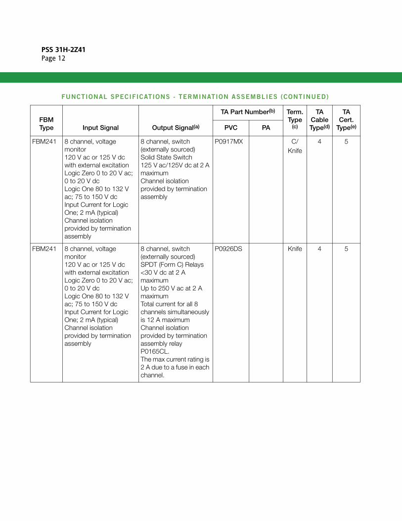
BM241 8 channel, voltage monitor120 V ac or 125 V dc with external excitationLogic Zero 0 to 20 V ac; 0 to 20 V dcLogic One 80 to 132 V ac; 75 to 150 V dcInput Current for Logic One; 2 mA (typical)Channel isolation provided by termination assembly
8 channel, switch (externally sourced)Solid State Switch 125 V ac/125V dc at 2 A maximumChannel isolation provided by termination assembly
P0917MX C/ Knife
4 5
BM241 8 channel, voltage monitor120 V ac or 125 V dc with external excitationLogic Zero 0 to 20 V ac; 0 to 20 V dcLogic One 80 to 132 V ac; 75 to 150 V dcInput Current for Logic One; 2 mA (typical) Channel isolation provided by termination assembly
8 channel, switch (externally sourced)SPDT (Form C) Relays<30 V dc at 2 A maximumUp to 250 V ac at 2 A maximumTotal current for all 8 channels simultaneously is 12 A maximumChannel isolation provided by termination assembly relay P0165CL.The max current rating is 2 A due to a fuse in each channel.
P0926DS Knife 4 5
FUNCTIONAL SPECIFICATIONS - TERMINATION ASSEMBLIES (CONTINUED)
FBM Type Input Signal Output Signal(a)
TA Part Number(b) Term.Type
(c)
TA Cable Type(d)
TA Cert.
Type(e)PVC PA
PSS 31H-2Z41Page 13
F
F
F
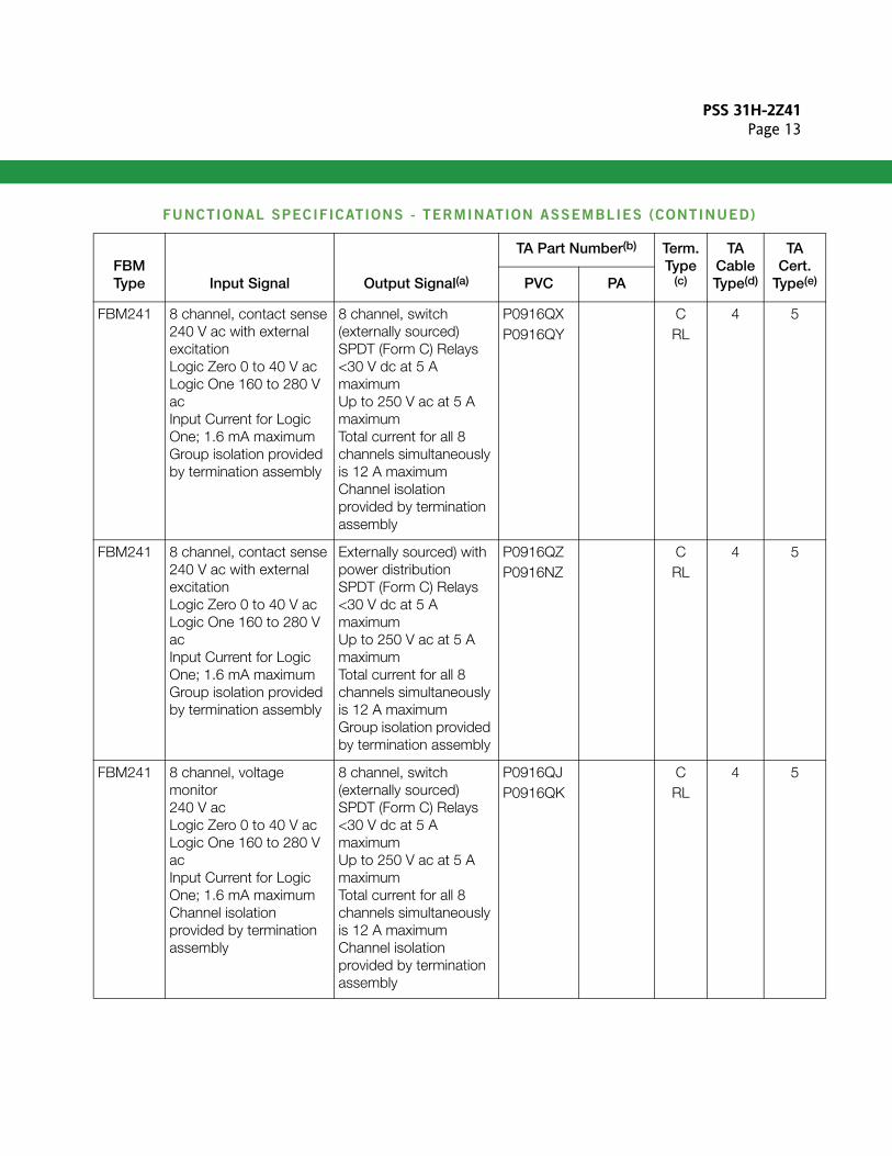
BM241 8 channel, contact sense240 V ac with external excitationLogic Zero 0 to 40 V acLogic One 160 to 280 V acInput Current for Logic One; 1.6 mA maximum Group isolation provided by termination assembly
8 channel, switch (externally sourced)SPDT (Form C) Relays<30 V dc at 5 A maximumUp to 250 V ac at 5 A maximumTotal current for all 8 channels simultaneously is 12 A maximumChannel isolation provided by termination assembly
P0916QXP0916QY
CRL
4 5
BM241 8 channel, contact sense240 V ac with external excitationLogic Zero 0 to 40 V acLogic One 160 to 280 V acInput Current for Logic One; 1.6 mA maximum Group isolation provided by termination assembly
Externally sourced) with power distributionSPDT (Form C) Relays<30 V dc at 5 A maximumUp to 250 V ac at 5 A maximumTotal current for all 8 channels simultaneously is 12 A maximumGroup isolation provided by termination assembly
P0916QZP0916NZ
CRL
4 5
BM241 8 channel, voltage monitor240 V acLogic Zero 0 to 40 V acLogic One 160 to 280 V acInput Current for Logic One; 1.6 mA maximumChannel isolation provided by termination assembly
8 channel, switch (externally sourced)SPDT (Form C) Relays<30 V dc at 5 A maximumUp to 250 V ac at 5 A maximumTotal current for all 8 channels simultaneously is 12 A maximumChannel isolation provided by termination assembly
P0916QJP0916QK
CRL
4 5
FUNCTIONAL SPECIFICATIONS - TERMINATION ASSEMBLIES (CONTINUED)
FBM Type Input Signal Output Signal(a)
TA Part Number(b) Term.Type
(c)
TA Cable Type(d)
TA Cert.
Type(e)PVC PA
PSS 31H-2Z41Page 14
F
F
F
F
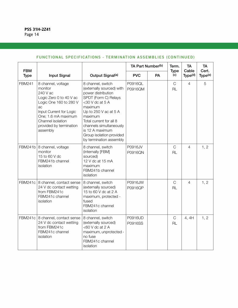
BM241 8 channel, voltage monitor240 V acLogic Zero 0 to 40 V acLogic One 160 to 280 V acInput Current for Logic One; 1.6 mA maximumChannel isolation provided by termination assembly
8 channel, switch (externally sourced) with power distributionSPDT (Form C) Relays<30 V dc at 5 A maximumUp to 250 V ac at 5 A maximumTotal current for all 8 channels simultaneously is 12 A maximumGroup isolation provided by termination assembly
P0916QLP0916QM
CRL
4 5
BM241b 8 channel, voltage monitor15 to 60 V dcFBM241b channel isolation
8 channel, switch (internally [FBM] sourced)12 V dc at 15 mA maximumFBM241b channel isolation
P0916JVP0916QN
CRL
4 1, 2
BM241c 8 channel, contact sense24 V dc contact wetting from FBM241cFBM241c channel isolation
8 channel, switch (externally sourced)15 to 60 V dc at 2 A maximum, protected - fusedFBM241c channel isolation
P0916JWP0916QP
CRL
4 1, 2
BM241c 8 channel, contact sense24 V dc contact wetting from FBM241cFBM241c channel isolation
8 channel, switch (externally sourced)<60 V dc at 2 A maximum, unprotected - no fuseFBM241c channel isolation
P0916UDP0916SS
CRL
4, 4H 1, 2
FUNCTIONAL SPECIFICATIONS - TERMINATION ASSEMBLIES (CONTINUED)
FBM Type Input Signal Output Signal(a)
TA Part Number(b) Term.Type
(c)
TA Cable Type(d)
TA Cert.
Type(e)PVC PA
PSS 31H-2Z41Page 15
F
F
F
(a) n
V
(b) o
(c)(d)(e)No
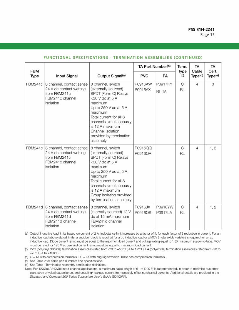
BM241c 8 channel, contact sense24 V dc contact wetting from FBM241cFBM241c channel isolation
8 channel, switch (externally sourced)SPDT (Form C) Relays<30 V dc at 5 A maximumUp to 250 V ac at 5 A maximumTotal current for all 8 channels simultaneously is 12 A maximumChannel isolation provided by termination assembly
P0916AWP0916AX
P0917KY
RL TA
CRL
4 3
BM241c 8 channel, contact sense24 V dc contact wetting from FBM241cFBM241c channel isolation
8 channel, switch (externally sourced)SPDT (Form C) Relays<30 V dc at 5 A maximumUp to 250 V ac at 5 A maximumTotal current for all 8 channels simultaneously is 12 A maximumGroup isolation provided by termination assembly
P0916QQP0916QR
CRL
4 1, 2
BM241d 8 channel, contact sense24 V dc contact wetting from FBM241d FBM241d channel isolation
8 channel, switch (internally sourced) 12 V dc at 15 mA maximumFBM241d channel isolation
P0916JXP0916QS
P0916YWP0917LA
CRL
4 1, 2
Output inductive load limits based on current of 2 A. Inductance limit increases by a factor of 4, for each factor of 2 reduction in current. For ainductive load above stated limits, a snubber diode is required for a dc inductive load or a MOV (metal oxide varistor) is required for an ac inductive load. Diode current rating must be equal to the maximum load current and voltage rating equal to 1.3X maximum supply voltage. MOmust be rated for 120 V ac use and current rating must be equal to maximum load current.PVC (polyvinyl chloride) termination assemblies rated from -20 to +50°C (-4 to 122°F); PA (polyamide) termination assemblies rated from -20 t+70°C (-4 to +158°F).C = TA with compression terminals, RL = TA with ring lug terminals. Knife has compression terminals.See Table 2 for cable part numbers and specifications.See Table 1Termination Assembly certification definitions.
te: For 120Vac / 240Vac input channel applications, a maximum cable length of 61 m (200 ft) is recommended, in order to minimize customerplant stray physical capacitance, and coupling/ leakage current from possibly effecting channel currents. Additional details are provided in theStandard and Compact 200 Series Subsystem User’s Guide (B0400FA).
FUNCTIONAL SPECIFICATIONS - TERMINATION ASSEMBLIES (CONTINUED)
FBM Type Input Signal Output Signal(a)
TA Part Number(b) Term.Type
(c)
TA Cable Type(d)
TA Cert.
Type(e)PVC PA
PSS 31H-2Z41Page 16
(f)
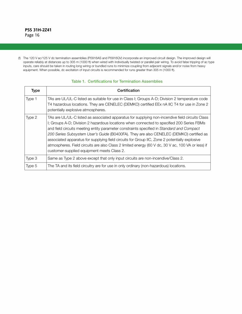
The 120 V ac/125 V dc termination assemblies (P0916AS and P0916QV) incorporate an improved circuit design. The improved design will operate reliably at distances up to 305 m (1000 ft) when wired with individually twisted or parallel pair wiring. To avoid false tripping of ac typeinputs, care should be taken in routing long wiring or bundled runs to minimize coupling from adjacent signals and/or noise from heavy equipment. When possible, dc excitation of input circuits is recommended for runs greater than 305 m (1000 ft).
Table 1. Certifications for Termination Assemblies
Type Certification
Type 1 TAs are UL/UL-C listed as suitable for use in Class I; Groups A-D; Division 2 temperature code T4 hazardous locations. They are CENELEC (DEMKO) certified EEx nA IIC T4 for use in Zone 2 potentially explosive atmospheres.
Type 2 TAs are UL/UL-C listed as associated apparatus for supplying non-incendive field circuits Class I; Groups A-D; Division 2 hazardous locations when connected to specified 200 Series FBMs and field circuits meeting entity parameter constraints specified in Standard and Compact 200 Series Subsystem User’s Guide (B0400FA). They are also CENELEC (DEMKO) certified as associated apparatus for supplying field circuits for Group IIC, Zone 2 potentially explosive atmospheres. Field circuits are also Class 2 limited energy (60 V dc, 30 V ac, 100 VA or less) if customer-supplied equipment meets Class 2.
Type 3 Same as Type 2 above except that only input circuits are non-incendive/Class 2.
Type 5 The TA and its field circuitry are for use in only ordinary (non-hazardous) locations.
PSS 31H-2Z41Page 17
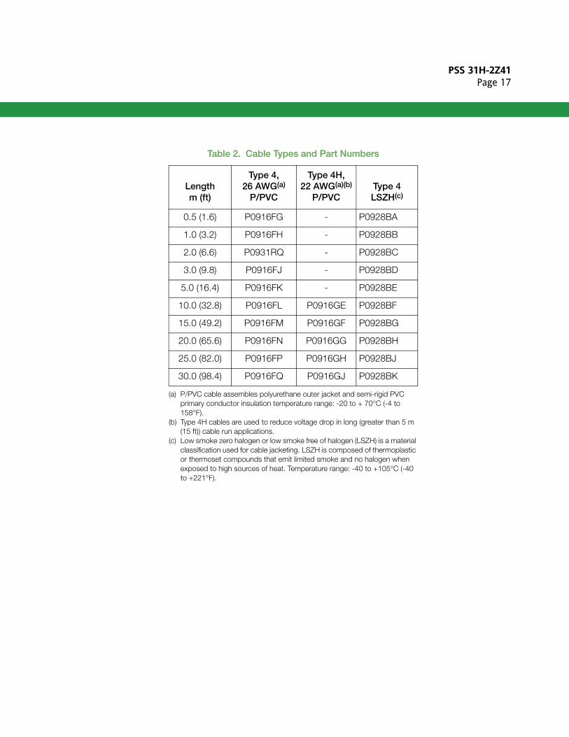
Table 2. Cable Types and Part Numbers
Lengthm (ft)
Type 4, 26 AWG(a)
P/PVC
Type 4H, 22 AWG(a)(b)
P/PVC Type 4LSZH(c)
0.5 (1.6) P0916FG - P0928BA
1.0 (3.2) P0916FH - P0928BB
2.0 (6.6) P0931RQ - P0928BC
3.0 (9.8) P0916FJ - P0928BD
5.0 (16.4) P0916FK - P0928BE
10.0 (32.8) P0916FL P0916GE P0928BF
15.0 (49.2) P0916FM P0916GF P0928BG
20.0 (65.6) P0916FN P0916GG P0928BH
25.0 (82.0) P0916FP P0916GH P0928BJ
30.0 (98.4) P0916FQ P0916GJ P0928BK
(a) P/PVC cable assembles polyurethane outer jacket and semi-rigid PVC primary conductor insulation temperature range: -20 to + 70°C (-4 to 158°F).
(b) Type 4H cables are used to reduce voltage drop in long (greater than 5 m (15 ft)) cable run applications.
(c) Low smoke zero halogen or low smoke free of halogen (LSZH) is a material classification used for cable jacketing. LSZH is composed of thermoplastic or thermoset compounds that emit limited smoke and no halogen when exposed to high sources of heat. Temperature range: -40 to +105°C (-40 to +221°F).
PSS 31H-2Z41Page 18
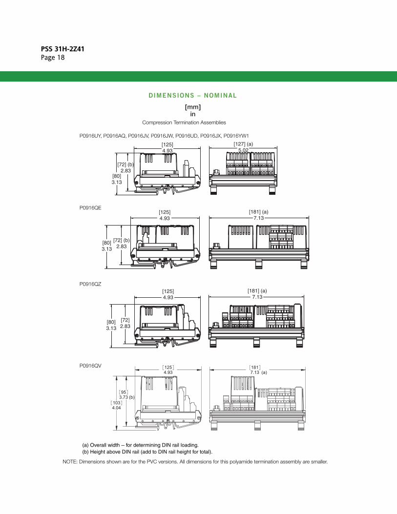
DIMENSIONS – NOMINAL
7.13 (a)181
4.93125
4.041033.73 (b)95
[125]4.93
[181] (a)7.13
[80]3.13
[72]2.83
P0916UY, P0916AQ, P0916JV, P0916JW, P0916UD, P0916JX, P0916YW1
P0916QZ
[125]4.93
[80]3.13
[72] (b)2.83
[127] (a)5.02
Compression Termination Assemblies
(a) Overall width – for determining DIN rail loading.(b) Height above DIN rail (add to DIN rail height for total).
[125]4.93
[80]3.13
[72] (b)2.83
[181] (a)7.13
P0916QE
NOTE: Dimensions shown are for the PVC versions. All dimensions for this polyamide termination assembly are smaller.
P0916QV
PSS 31H-2Z41Page 19
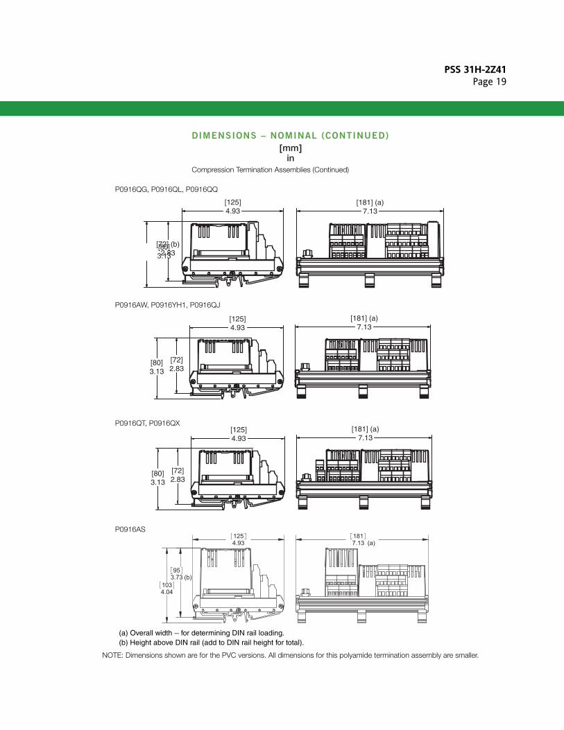
DIMENSIONS – NOMINAL (CONTINUED)
7.13 (a)181
4.93125
4.041033.73 (b)95
[125]4.93
[181] (a)7.13
[80]3.13
[72]2.83
(a) Overall width – for determining DIN rail loading.(b) Height above DIN rail (add to DIN rail height for total).
[125]4.93
[181] (a)7.13
[80]3.13
[72]2.83
P0916QT, P0916QX
[125]4.93
[181] (a)7.13
[80]3.13
[72] (b)2.83
Compression Termination Assemblies (Continued)
P0916AW, P0916YH1, P0916QJ
NOTE: Dimensions shown are for the PVC versions. All dimensions for this polyamide termination assembly are smaller.
P0916QG, P0916QL, P0916QQ
P0916AS
PSS 31H-2Z41Page 20
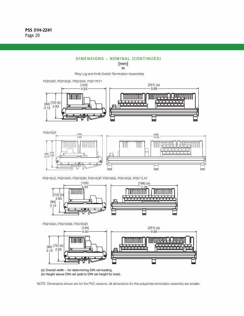
DIMENSIONS – NOMINAL (CONTINUED)
[80]3.13
[72] (b)2.83
[251] (a)9.88
[125]4.93
P0916QH, P0916QM, P0916QR
P0916UZ, P0916AR, P0916QN, P0916QP, P0916SS, P0916QS, P0917LA1
(a) Overall width – for determining DIN rail loading. (b) Height above DIN rail (add to DIN rail height for total).
[125]4.93
[80]3.13
[72] (b)2.83
[198] (a)7.78
RIng Lug and Knife Switch Termination Assemblies
[251] (a)9.88
[80]3.13
[72] (b)2.83
[125]4.93
NOTE: Dimensions shown are for the PVC versions. All dimensions for this polyamide termination assembly are smaller.
P0916AT, P0916QK, P0916AX, P0917KY1
[125]4.93
[268]10.53
[72]2.83
[80]3.13
P0916QF
PSS 31H-2Z41Page 21
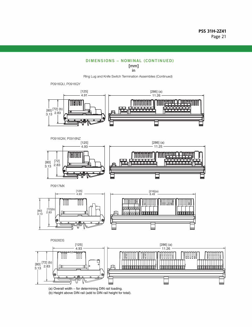
DIMENSIONS – NOMINAL (CONTINUED)
[80]3.13
[72]2.83
[286] (a)11.25
[125]4.93
P0916QW, P0916NZ
(a) Overall width – for determining DIN rail loading. (b) Height above DIN rail (add to DIN rail height for total).
RIng Lug and Knife Switch Termination Assemblies (Continued)
P0926DS
3.13[80] 2.83
[72](b)
[216](a)4.93[125]
8.49
P0917MX
[80]3.13
[72] (b)2.83
[125]4.93
[286] (a)11.26
P0916QU, P0916QY
[80]3.13
[72] (b)2.83
[125]4.91
[286] (a)11.26
PSS 31H-2Z41Page 22
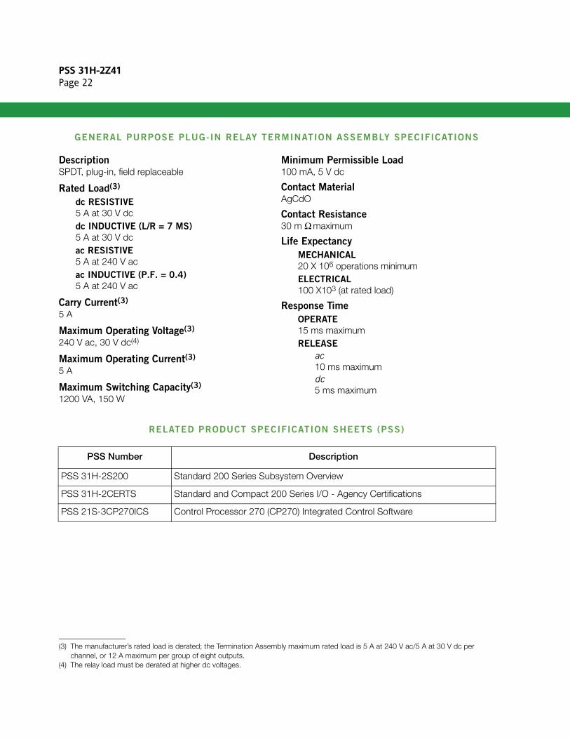
GENERAL PURPOSE PLUG-IN RELAY TERMINATION ASSEMBLY SPECIFICATIONS
DescriptionSPDT, plug-in, field replaceable
Rated Load(3)
dc RESISTIVE
5 A at 30 V dc dc INDUCTIVE (L/R = 7 MS)
5 A at 30 V dc ac RESISTIVE
5 A at 240 V acac INDUCTIVE (P.F. = 0.4)
5 A at 240 V ac
Carry Current(3)
5 A
Maximum Operating Voltage(3)
240 V ac, 30 V dc(4)
Maximum Operating Current(3)
5 A
Maximum Switching Capacity(3)
1200 VA, 150 W
Minimum Permissible Load100 mA, 5 V dc
Contact MaterialAgCdO
Contact Resistance30 m Ω maximum
Life Expectancy
MECHANICAL
20 X 106 operations minimumELECTRICAL
100 X103 (at rated load)
Response Time
OPERATE
15 ms maximumRELEASE
ac10 ms maximumdc5 ms maximum
RELATED PRODUCT SPECIFICATION SHEETS (PSS)
(3) The manufacturer’s rated load is derated; the Termination Assembly maximum rated load is 5 A at 240 V ac/5 A at 30 V dc per channel, or 12 A maximum per group of eight outputs.
(4) The relay load must be derated at higher dc voltages.
PSS Number Description
PSS 31H-2S200 Standard 200 Series Subsystem Overview
PSS 31H-2CERTS Standard and Compact 200 Series I/O - Agency Certifications
PSS 21S-3CP270ICS Control Processor 270 (CP270) Integrated Control Software

PSS 31H-2Z41Page 23

PSS 31H-2Z41Page 24
Invensys Systems, Inc10900 Equity DriveHouston, TX 77041United States of Americahttp://www.invensys.com
Global Customer SupportInside U.S.: 1-866-746-6477Outside U.S.: 1-508-549-2424 Website: https://support.ips.invensys.com
Copyright 2014 Invensys Systems, Inc. All rights reserved. Invensys is now part of Schneider Electric.
Invensys, Foxboro, and Foxboro Evo are trademarks owned by Invensys Limited, its subsidiaries and affiliates.All other trademarks are the property of their respectiveowners.
MB 031 1214