Embed Size (px)
Citation preview
I N V
E N
T I
V E
HW/SW Verification from an Open SystemC virtual prototype through simulation, emulation, and FPGA prototyping Quo Vadis, Virtual Platforms? Challenges and Solutions for Today and Tomorrow Design, Automation, and Test in Europe (DATE 2012) Dresden, Germany Markus Winterholer Solutions Architect [email protected]

I N V
E N
T I
V E
Virtual Prototypes for Embedded Software Verification
European SystemC User’s Group Workshop: OSCI and Accellera Core Technologies for the Next Generation of System-Level Design Design, Automation, and Test in Europe (DATE 2012) Dresden, Germany Markus Winterholer Solutions Architect [email protected]
© 2012 Cadence Design Systems, Inc.
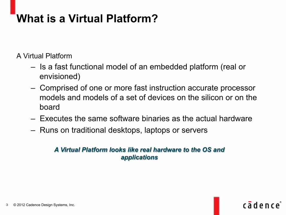
A Virtual Platform – Is a fast functional model of an embedded platform (real or
envisioned) – Comprised of one or more fast instruction accurate processor
models and models of a set of devices on the silicon or on the board
– Executes the same software binaries as the actual hardware – Runs on traditional desktops, laptops or servers
What is a Virtual Platform?
3
A Virtual Platform looks like real hardware to the OS and applications
© 2012 Cadence Design Systems, Inc.
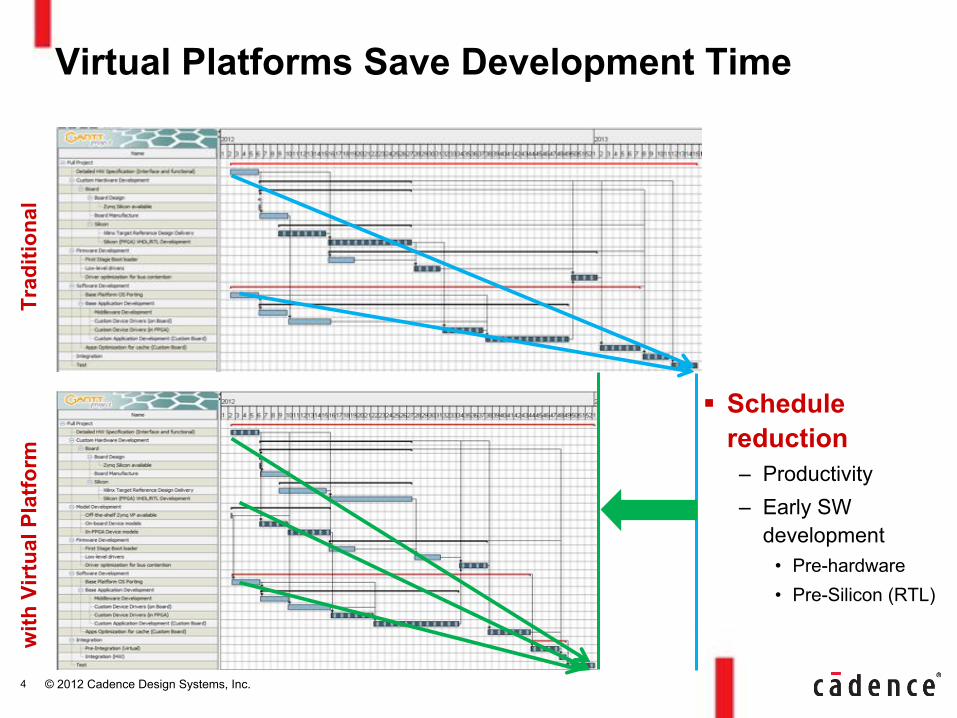
Virtual Platforms Save Development Time
4
Trad
ition
al
with
Virt
ual P
latfo
rm
! Schedule reduction
– Productivity – Early SW
development • Pre-hardware • Pre-Silicon (RTL)
© 2012 Cadence Design Systems, Inc.
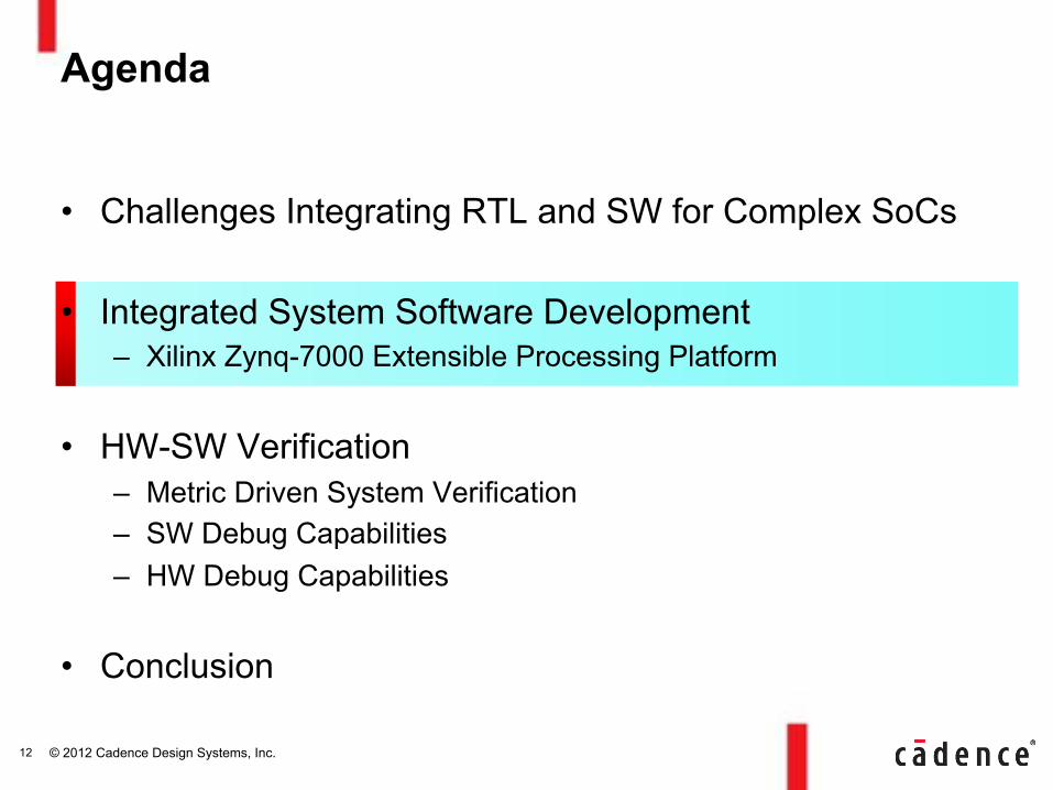
• Challenges Integrating RTL and SW for Complex SoCs
• Integrated System Software Development – Xilinx Zynq-7000 Extensible Processing Platform
• HW-SW Verification – Metric Driven System Verification – SW Debug Capabilities – HW Debug Capabilities
• Conclusion
Agenda
5

© 2012 Cadence Design Systems, Inc.
Exploding SoC and SW Development Effort Dominated by Design Integration and Verification
Source: Semico Research Corp.
$0##
$50##
$100##
$150##
$200##
$250##
90nm# 65nm# 45nm#/#40nm# 32nm#/#28nm# 20nm*# 14nm*#
So#ware( HW(Architecture(&(Verifica4on( HW(Implementa4on(&(Valida4on(
Mill
ions
($M
)
© 2012 Cadence Design Systems, Inc.
Verification Environment Repeatable stimulus for dozen’s of interfaces
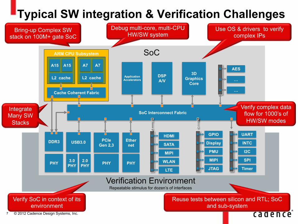
Typical SW integration & Verification Challenges
SoC
SoC Interconnect Fabric
ARM CPU Subsystem
Application Accelerators
DSP A/V
DDR3
PHY
SATA
MIPI
HDMI
WLAN
LTE
PMU
MIPI
JTAG
INTC
I2C
SPI
Timer
GPIO
Display
UART
3D Graphics
Core …
AES
…
A15
L2 cache
USB3.0
3.0 PHY
2.0 PHY
PCIe Gen 2,3
PHY
Ether net
PHY
A15 A7
L2 cache
A7
Cache Coherent Fabric
Use OS & drivers to verify complex IPs
Debug multi-core, multi-CPU HW/SW system
Verify complex data flow for 1000’s of HW/SW modes
Integrate Many SW
Stacks
Bring-up Complex SW stack on 100M+ gate SoC
Reuse tests between silicon and RTL; SoC and sub-system
Integrate Many SW
Stacks
Verify SoC in context of its environment
7
© 2012 Cadence Design Systems, Inc.
Speeed Bridge ROM
Speed Bridge
Speed Bridge ROM
ROM
Embedded Test
Bench
Embedded AVIP
Embedded AVIP
Embedded AVIP
Embedded AVIP
Embedded AVIP
Embedded AVIP
Large
RTL Block UVM Test
Bench
VIP
VIP
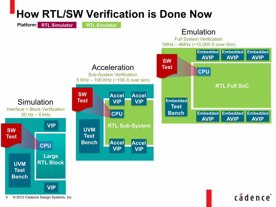
How RTL/SW Verification is Done Now RTL Emulator RTL Simulator Platform:
RTL Full SoC
CPU
RTL Sub-System
CPU
Accel VIP
UVM Test
Bench
Accel VIP
Accel VIP
Accel VIP Simulation
Interface + Block Verification 50 Hz – 5 kHz
Acceleration Sub-System Verification
5 KHz – 100 KHz (~100 X over sim)
Emulation Full System Verification
1MHz – 4MHz (~10,000 X over Sim)
CPU
SW Test
SW Test
SW Test
8
© 2012 Cadence Design Systems, Inc.
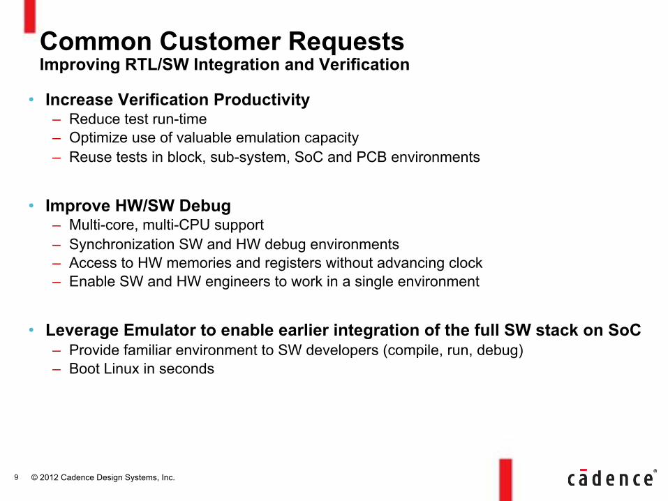
• Increase Verification Productivity – Reduce test run-time – Optimize use of valuable emulation capacity – Reuse tests in block, sub-system, SoC and PCB environments
• Improve HW/SW Debug – Multi-core, multi-CPU support – Synchronization SW and HW debug environments – Access to HW memories and registers without advancing clock – Enable SW and HW engineers to work in a single environment
• Leverage Emulator to enable earlier integration of the full SW stack on SoC – Provide familiar environment to SW developers (compile, run, debug) – Boot Linux in seconds
Common Customer Requests Improving RTL/SW Integration and Verification
9
© 2012 Cadence Design Systems, Inc.
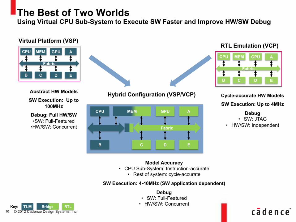
The Best of Two Worlds Using Virtual CPU Sub-System to Execute SW Faster and Improve HW/SW Debug
RTL TLM Key:
Fabric
MEM GPU A
C D E
CPU
B
Bridge
Fabric
MEM GPU A
C D E
CPU
B
Abstract HW Models
SW Execution: Up to 100MHz
Debug: Full HW/SW • SW: Full-Featured
• HW/SW: Concurrent
Cycle-accurate HW Models
SW Execution: Up to 4MHz
Debug • SW: JTAG
• HW/SW: Independent
Model Accuracy • CPU Sub-System: Instruction-accurate
• Rest of system: cycle-accurate
SW Execution: 4-40MHz (SW application dependent)
Debug • SW: Full-Featured
• HW/SW: Concurrent
Virtual Platform (VSP) RTL Emulation (VCP)
Hybrid Configuration (VSP/VCP)
MEM GPU A
C D E
CPU
B
Fabric
10
© 2012 Cadence Design Systems, Inc.
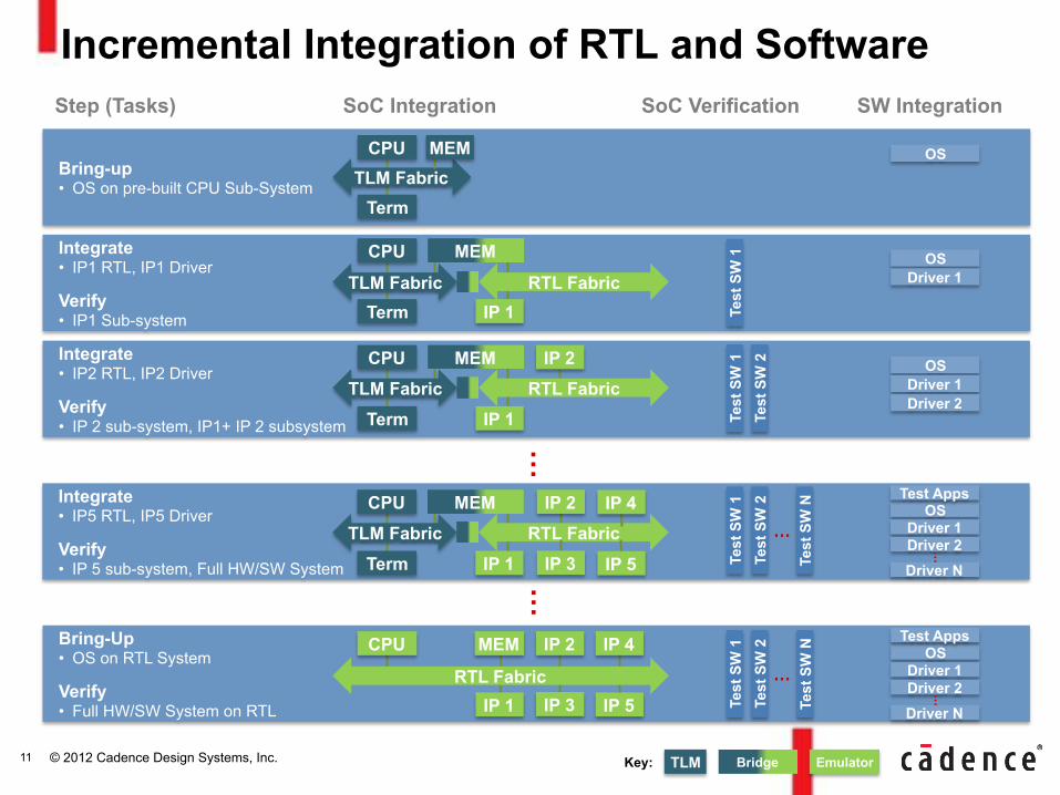
Incremental Integration of RTL and Software
…
Step (Tasks) SoC Integration SW Integration
Bring-up • OS on pre-built CPU Sub-System TLM Fabric
MEM CPU
Term
OS
Integrate • IP1 RTL, IP1 Driver
Verify • IP1 Sub-system
MEM CPU
IP 1 Term
OS Driver 1
Test
SW
1
RTL Fabric TLM Fabric
Integrate • IP2 RTL, IP2 Driver
Verify • IP 2 sub-system, IP1+ IP 2 subsystem
MEM IP 2 CPU
IP 1 Term
OS Driver 1 Driver 2
Test
SW
1
Test
SW
2
RTL Fabric TLM Fabric
Bring-Up • OS on RTL System
Verify • Full HW/SW System on RTL
MEM IP 2 IP 4 CPU
IP 1 IP 5 IP 3
OS Driver 1
Driver N
Test Apps
Driver 2 … Te
st S
W 1
Te
st S
W 2
Test
SW
N
…RTL Fabric
…
Integrate • IP5 RTL, IP5 Driver
Verify • IP 5 sub-system, Full HW/SW System
MEM IP 2 CPU
IP 1 Term RTL Fabric TLM Fabric
IP 4
IP 5 IP 3
OS Driver 1
Driver N
Test Apps
Driver 2 … Te
st S
W 1
Te
st S
W 2
Test
SW
N
…
SoC Verification
Emulator TLM Key: Bridge 11
© 2012 Cadence Design Systems, Inc.
• Challenges Integrating RTL and SW for Complex SoCs
• Integrated System Software Development – Xilinx Zynq-7000 Extensible Processing Platform
• HW-SW Verification – Metric Driven System Verification – SW Debug Capabilities – HW Debug Capabilities
• Conclusion
Agenda
12

© 2012 Cadence Design Systems, Inc.
Zynq-7000 EPP System Level Block Diagram
13
© 2012 Cadence Design Systems, Inc.
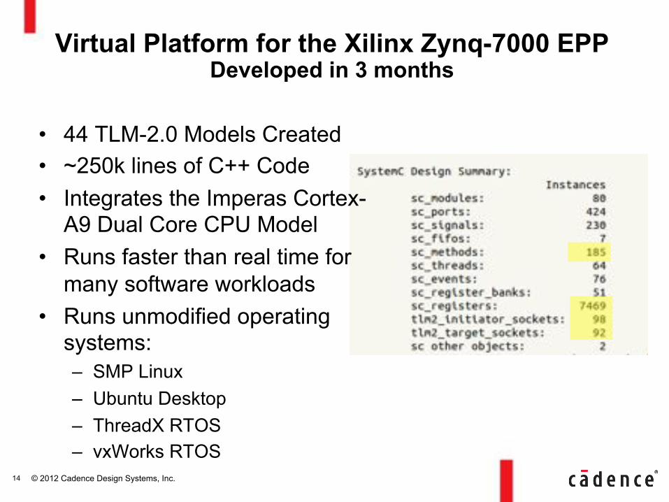
Virtual Platform for the Xilinx Zynq-7000 EPP Developed in 3 months
• 44 TLM-2.0 Models Created • ~250k lines of C++ Code • Integrates the Imperas Cortex-
A9 Dual Core CPU Model • Runs faster than real time for
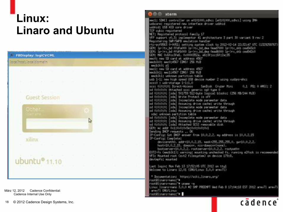
many software workloads • Runs unmodified operating
systems: – SMP Linux – Ubuntu Desktop – ThreadX RTOS – vxWorks RTOS
14
© 2012 Cadence Design Systems, Inc.
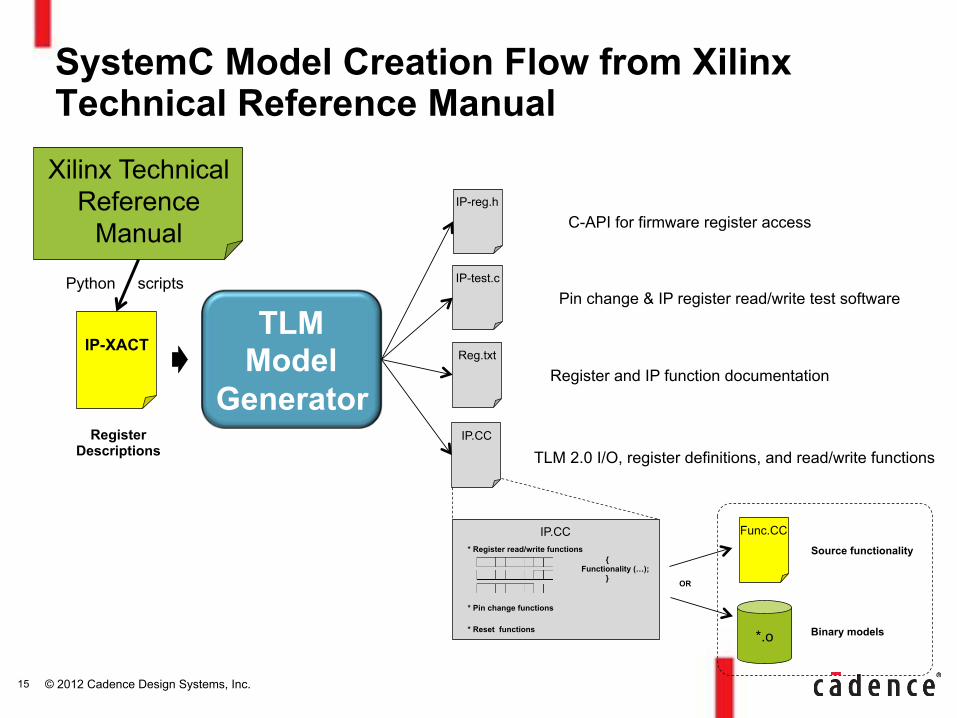
SystemC Model Creation Flow from Xilinx Technical Reference Manual
TLM Model
Generator Register
Descriptions
C-API for firmware register access IP-reg.h
IP-test.c
Pin change & IP register read/write test software
Reg.txt
Register and IP function documentation
IP.CC
TLM 2.0 I/O, register definitions, and read/write functions
IP.CC * Register read/write functions
* Pin change functions
* Reset functions
{ Functionality (…);
}
*.o
Func.CC
OR
Source functionality
Binary models
IP-XACT
Xilinx Technical Reference
Manual
Python scripts
15
© 2012 Cadence Design Systems, Inc.
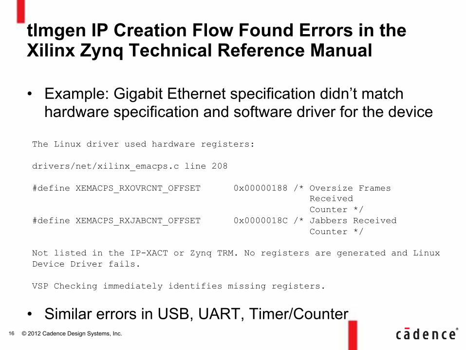
tlmgen IP Creation Flow Found Errors in the Xilinx Zynq Technical Reference Manual
• Example: Gigabit Ethernet specification didn’t match hardware specification and software driver for the device
• Similar errors in USB, UART, Timer/Counter
The Linux driver used hardware registers: drivers/net/xilinx_emacps.c line 208 #define XEMACPS_RXOVRCNT_OFFSET 0x00000188 /* Oversize Frames Received Counter */ #define XEMACPS_RXJABCNT_OFFSET 0x0000018C /* Jabbers Received Counter */ Not listed in the IP-XACT or Zynq TRM. No registers are generated and Linux Device Driver fails. VSP Checking immediately identifies missing registers.
16
© 2012 Cadence Design Systems, Inc.
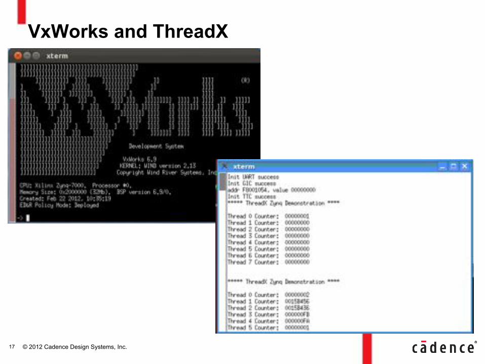
VxWorks and ThreadX
17
© 2012 Cadence Design Systems, Inc.
Linux: Linaro and Ubuntu
März 12, 2012 Cadence Confidential: Cadence Internal Use Only
18
© 2012 Cadence Design Systems, Inc.
• Challenges Integrating RTL and SW for Complex SoCs
• Integrated System Software Development – Xilinx Zynq-7000 Extensible Processing Platform
• HW-SW Verification – Metric Driven System Verification – SW Debug Capabilities – HW Debug Capabilities
• Conclusion
Agenda
19
© 2012 Cadence Design Systems, Inc.
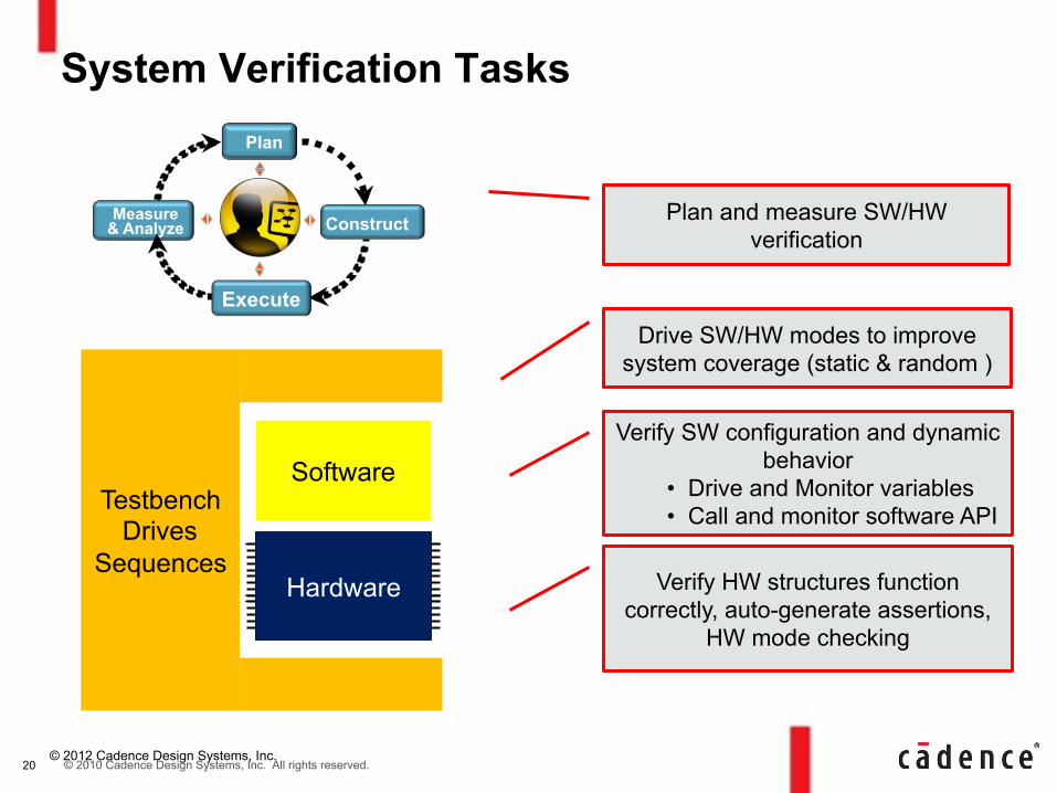
System Verification Tasks
Hardware
Software Testbench
Drives Sequences
Verify HW structures function correctly, auto-generate assertions,
HW mode checking
Verify SW configuration and dynamic behavior
• Drive and Monitor variables • Call and monitor software API
Drive SW/HW modes to improve system coverage (static & random )
Plan and measure SW/HW verification
Measure & Analyze
Execute
Construct
Plan
20 © 2010 Cadence Design Systems, Inc. All rights reserved.
© 2012 Cadence Design Systems, Inc.
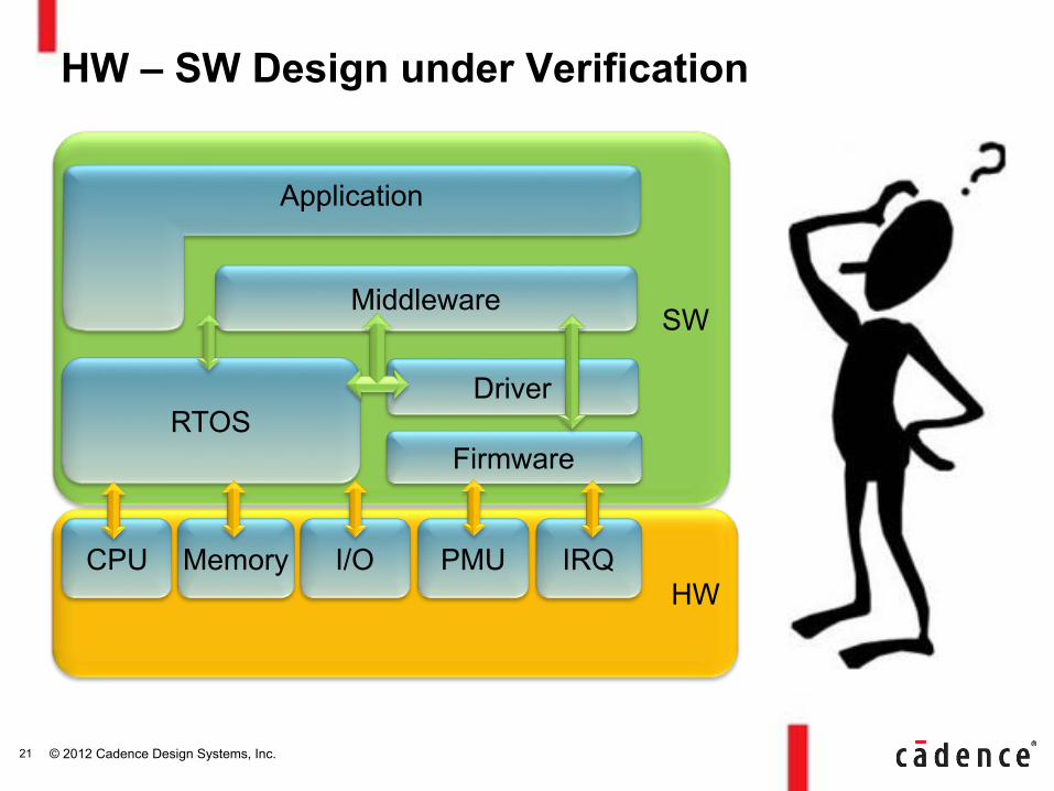
HW
SW
HW – SW Design under Verification
Middleware
Application
RTOS Firmware
Driver
CPU Memory I/O PMU IRQ
21
© 2012 Cadence Design Systems, Inc.
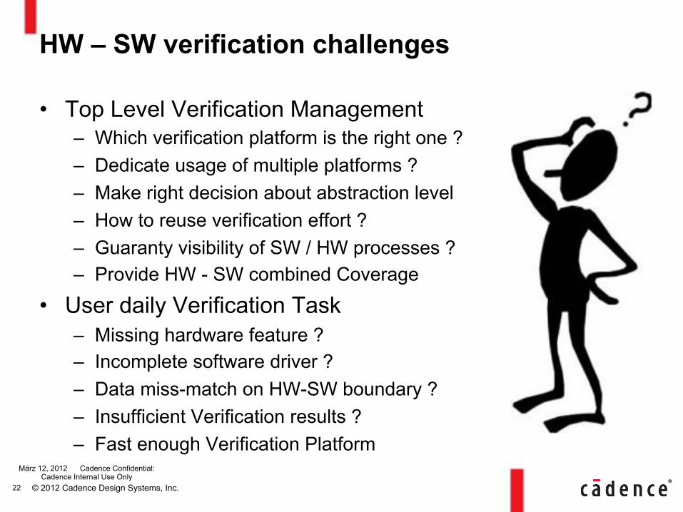
HW – SW verification challenges
• Top Level Verification Management – Which verification platform is the right one ? – Dedicate usage of multiple platforms ? – Make right decision about abstraction level – How to reuse verification effort ? – Guaranty visibility of SW / HW processes ? – Provide HW - SW combined Coverage
• User daily Verification Task – Missing hardware feature ? – Incomplete software driver ? – Data miss-match on HW-SW boundary ? – Insufficient Verification results ? – Fast enough Verification Platform
• To whom ?
März 12, 2012 Cadence Confidential: Cadence Internal Use Only
22

© 2012 Cadence Design Systems, Inc.
HW – SW Verification
HW
SW Middleware
Application
RTOS Firmware
Driver
CPU Memory I/O PMU IRQ CVE
UVM
OVM
SCV
C++
eRM
FPGA Sim
Silicon
Virtual
Hybride
HCE
whitebox random
reuse variables
State machine Coverage
untimed
Cycle accurate
23
© 2012 Cadence Design Systems, Inc.
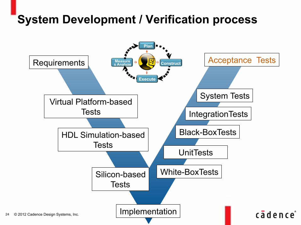
System Development / Verification process
Virtual Platform-based Tests
White-BoxTests
Black-BoxTests
IntegrationTests
System Tests
Measure & Analyze
Execute
Construct
Plan
UnitTests
HDL Simulation-based Tests
Silicon-based Tests
Acceptance Tests Requirements
Implementation 24
© 2012 Cadence Design Systems, Inc.
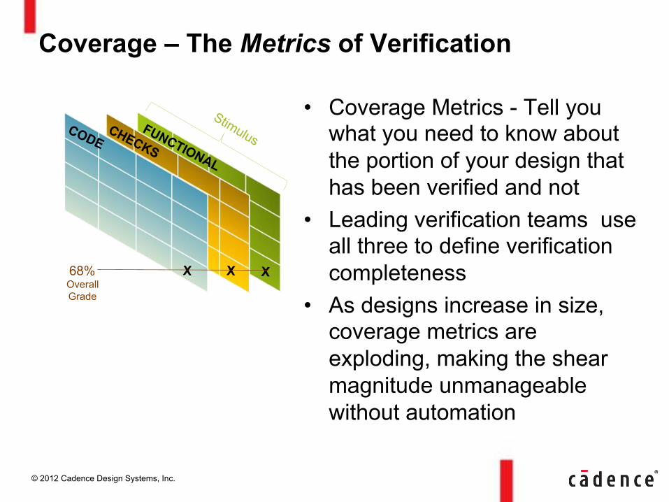
Coverage – The Metrics of Verification
• Coverage Metrics - Tell you what you need to know about the portion of your design that has been verified and not
• Leading verification teams use all three to define verification completeness
• As designs increase in size, coverage metrics are exploding, making the shear magnitude unmanageable without automation
X X X 68% Overall Grade
© 2012 Cadence Design Systems, Inc.
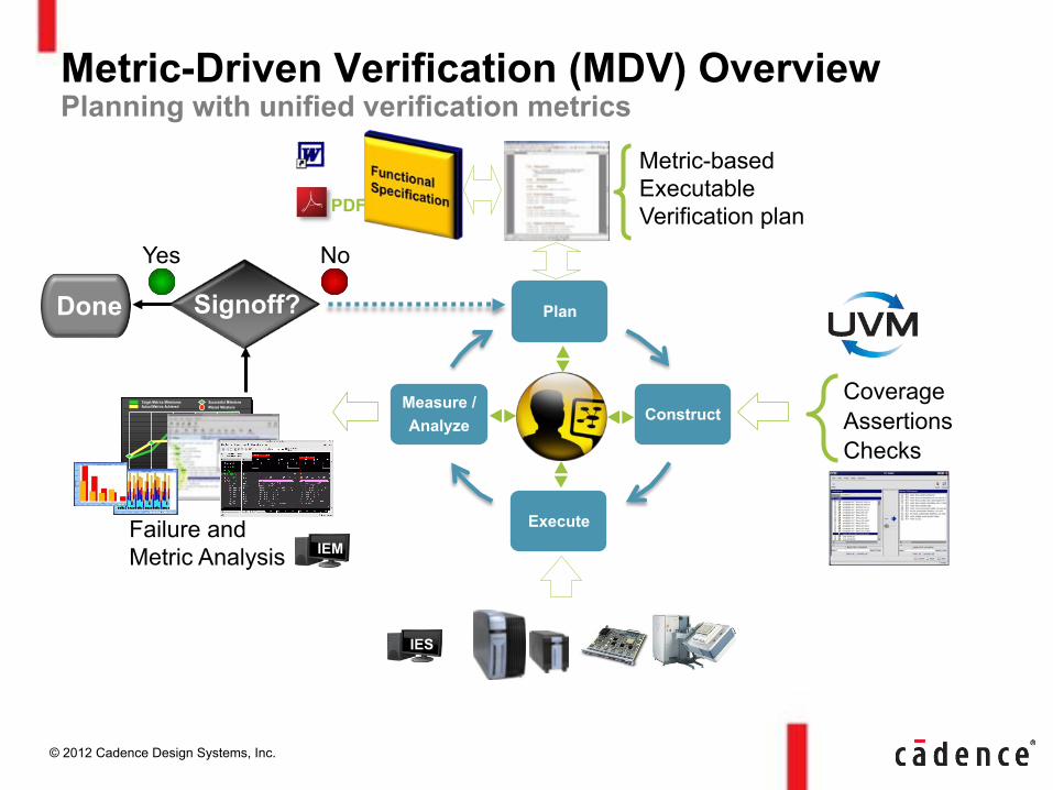
Plan
Construct
Execute
Measure / Analyze
Metric-Driven Verification (MDV) Overview Planning with unified verification metrics
Done
Yes No
Signoff?
Metric-based Executable Verification plan PDF
VE Start ProductionPrototypeChipIntegration
ModuleSet Two
ModuleSet One
Actual Metrics AchievedTarget Metrics Milestones
Missed MilestoneSuccessful Milestone
VE Start ProductionPrototypeChipIntegration
ModuleSet Two
ModuleSet One
Actual Metrics AchievedTarget Metrics Milestones
Missed MilestoneSuccessful Milestone
Failure and Metric Analysis IEM
Checks Assertions Coverage
IES
© 2012 Cadence Design Systems, Inc.
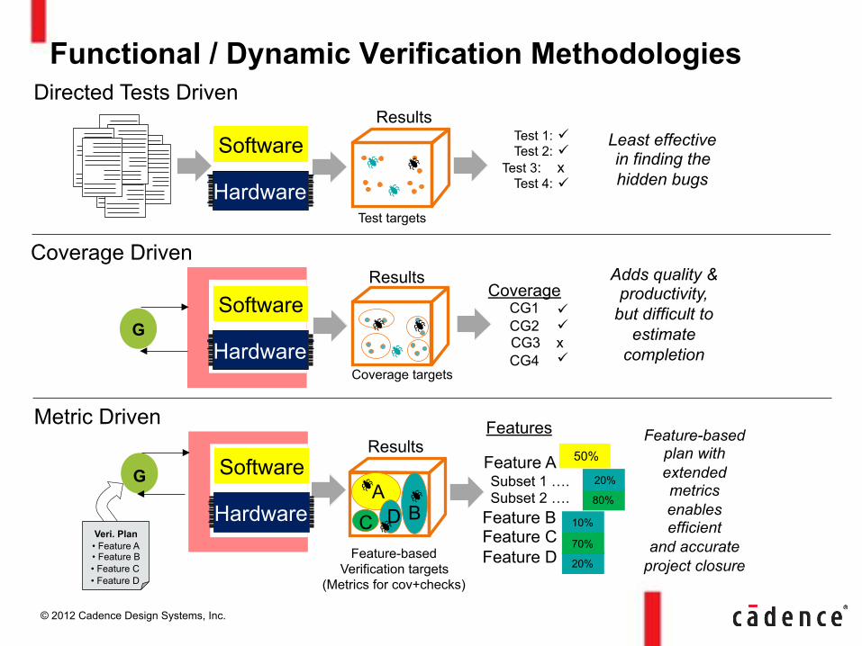
Functional / Dynamic Verification Methodologies
Test targets
Test 1: Test 2:
Test 3: x Test 4:
" "
"
Least effective in finding the hidden bugs
Directed Tests Driven Results
G
Coverage CG1 CG2
CG3 x CG4
" "
"
Coverage Driven Results Adds quality &
productivity, but difficult to
estimate completion
Coverage targets
80%
20%
10%
70%
G
Features
Feature A Subset 1 …. Subset 2 ….
Feature B Feature C Feature D
Veri. Plan • Feature A • Feature B • Feature C • Feature D
Metric Driven
50%
20%
Feature-based plan with extended metrics enables efficient
and accurate project closure
Results
A B D C
Feature-based Verification targets
(Metrics for cov+checks)
Hardware
Software
Hardware
Software
Hardware
Software
© 2012 Cadence Design Systems, Inc. 28
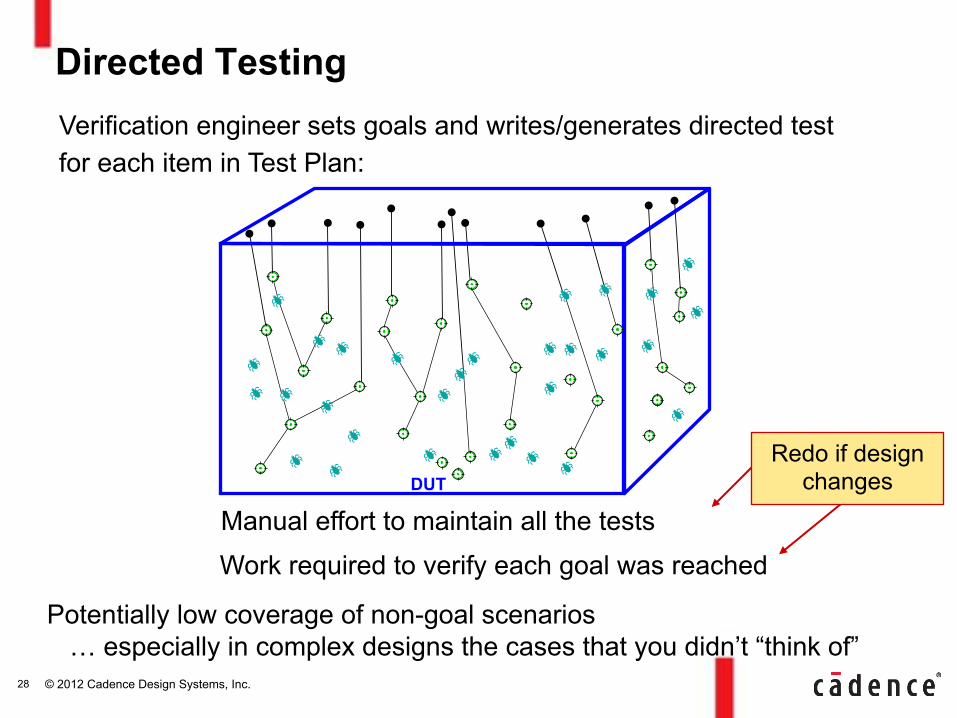
Directed Testing
Redo if design changes
Manual effort to maintain all the tests
Work required to verify each goal was reached
Potentially low coverage of non-goal scenarios … especially in complex designs the cases that you didn’t “think of”
DUT
Verification engineer sets goals and writes/generates directed test for each item in Test Plan:
© 2012 Cadence Design Systems, Inc. 29
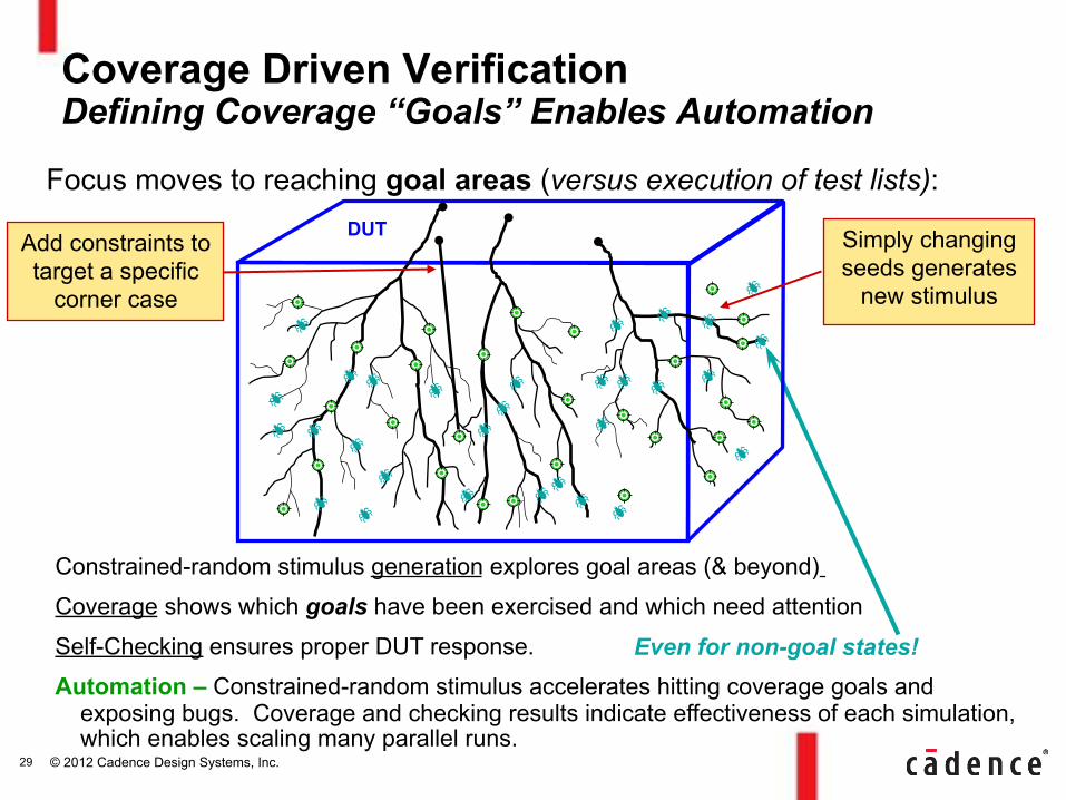
Focus moves to reaching goal areas (versus execution of test lists):
Constrained-random stimulus generation explores goal areas (& beyond)
Coverage shows which goals have been exercised and which need attention
Self-Checking ensures proper DUT response.
Automation – Constrained-random stimulus accelerates hitting coverage goals and exposing bugs. Coverage and checking results indicate effectiveness of each simulation, which enables scaling many parallel runs.
Coverage Driven Verification Defining Coverage “Goals” Enables Automation
Even for non-goal states!
DUT Simply changing seeds generates
new stimulus
Add constraints to target a specific
corner case
© 2012 Cadence Design Systems, Inc. 30
hw-dut sw-driver
sw-sequencer Scoreboard
modelRegister s transaction transaction monitor monitor
stimulus
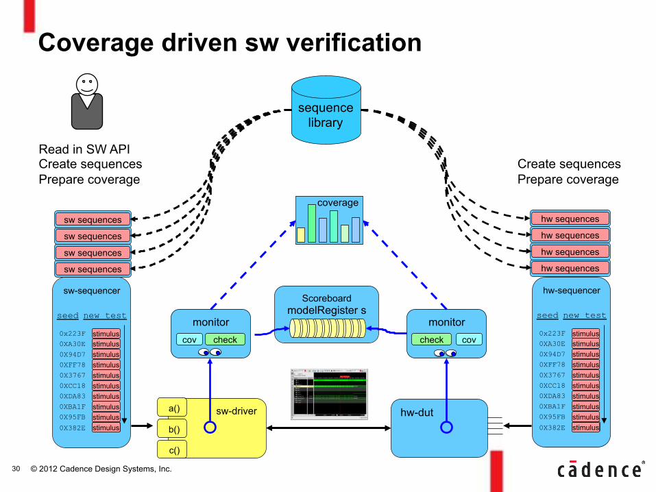
Coverage driven sw verification
0x223F stimulus 0XA30E 0X94D7 0XFF78 0X3767 0XCC18 0XDA83 0XBA1F 0X95FB 0X382E
stimulus stimulus stimulus stimulus stimulus stimulus stimulus stimulus stimulus
seed new test
coverage
check check cov cov
sw sequences
sw sequences
sw sequences
sw sequences
sequence library
hw sequences
hw sequences
hw sequences
hw sequences
hw-sequencer
stimulus
0x223F stimulus 0XA30E 0X94D7 0XFF78 0X3767 0XCC18 0XDA83 0XBA1F 0X95FB 0X382E
stimulus stimulus stimulus stimulus stimulus stimulus stimulus stimulus stimulus
seed new test
Read in SW API Create sequences Prepare coverage
b()
c()
a()
Create sequences Prepare coverage
© 2012 Cadence Design Systems, Inc.
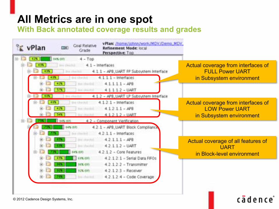
All Metrics are in one spot With Back annotated coverage results and grades
Actual coverage from interfaces of FULL Power UART
in Subsystem environment
Actual coverage of all features of UART
in Block-level environment
Actual coverage from interfaces of LOW Power UART
in Subsystem environment
© 2012 Cadence Design Systems, Inc.
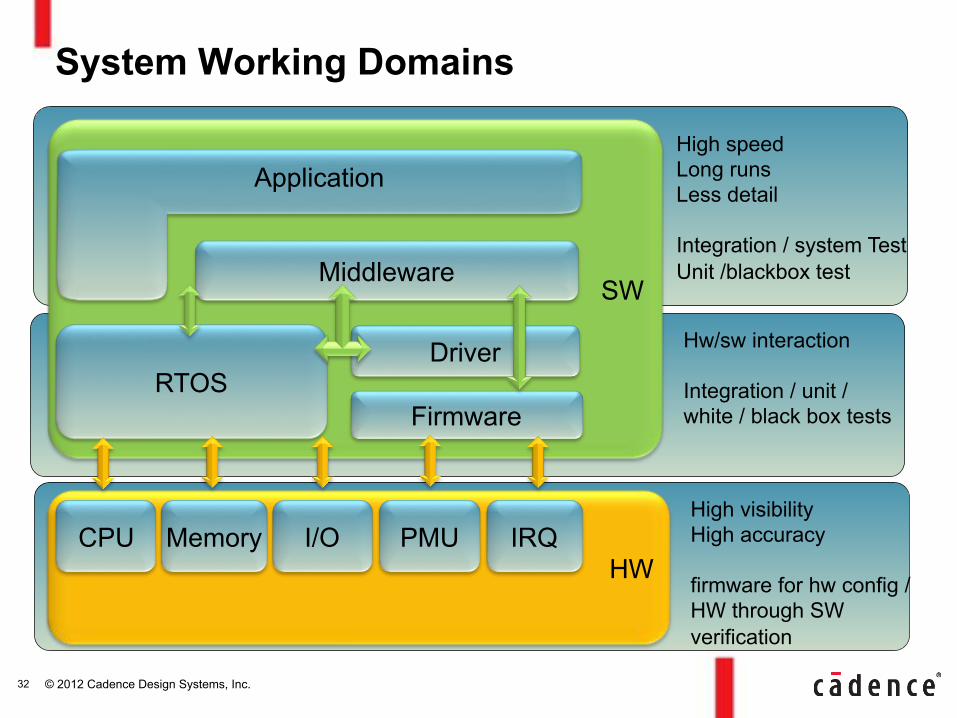
HW
SW
System Working Domains
Middleware
Application
RTOS Firmware
Driver
CPU Memory I/O PMU IRQ
High speed Long runs Less detail Integration / system Test Unit /blackbox test
Hw/sw interaction Integration / unit / white / black box tests
High visibility High accuracy firmware for hw config / HW through SW verification
32
© 2012 Cadence Design Systems, Inc.
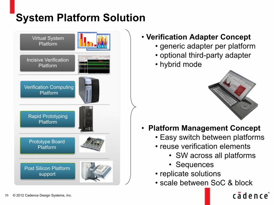
• Verification Adapter Concept • generic adapter per platform • optional third-party adapter • hybrid mode
• Platform Management Concept
• Easy switch between platforms • reuse verification elements
• SW across all platforms • Sequences
• replicate solutions • scale between SoC & block
System Platform Solution Rapid Prototyping
Platform Virtual System
Platform
Incisive Verification Platform
Rapid Prototyping Platform
Verification Computing Platform
Prototype Board Platform
Post Silicon Platform support
33
© 2012 Cadence Design Systems, Inc.
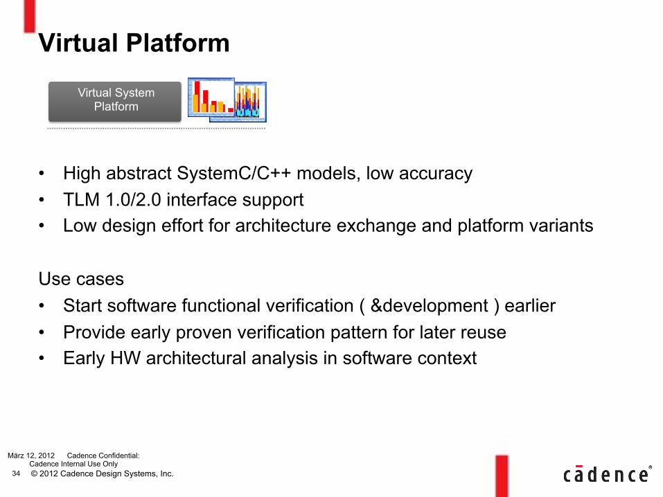
Virtual Platform
• High abstract SystemC/C++ models, low accuracy • TLM 1.0/2.0 interface support • Low design effort for architecture exchange and platform variants
Use cases • Start software functional verification ( &development ) earlier • Provide early proven verification pattern for later reuse • Early HW architectural analysis in software context
März 12, 2012 Cadence Confidential: Cadence Internal Use Only
Virtual System Platform
34
© 2012 Cadence Design Systems, Inc.
Incisive Simulation
• Design models in VHDL, Verilog, SystemC/C supported • Higher accuracy but slower speed than Virtual Platform • Support for mixed abstraction levels • Best HW debug platform
Use cases • Block level HW verification with dynamic software context • Reactive HW-SW verification increased coverage • Optimized SW verification infrastructure ( less code ) • Embedded Software verification on more accurate HW/SW interface • Use of specific test software for hw stress tests
März 12, 2012 Cadence Confidential: Cadence Internal Use Only
Incisive Verification Platform
35

© 2012 Cadence Design Systems, Inc.
Verification Computing and Rapid Prototyping
• Full synthesizable HW models • Highest Speed for SW on prototype platform • Easy migration between both platforms
Use cases • Find HW/SW corner-cases hidden in long software runs • Reuse of block level tests in SOC environment • Verification of SW drivers and applications with real HW to find
timing issues and verify complex SOC scenarios • System level low-power stress verification on PXP
März 12, 2012 Cadence Confidential: Cadence Internal Use Only
Rapid Prototyping Platform
Verification Computing Platform
36
© 2012 Cadence Design Systems, Inc.
Ccustom Prototype
• Software verification and development on custom based HW platform
• Highest execution speed • Full customized and individual verification environment based on
standard System Verifier mechanisms
Use cases • Verification of SW drivers and applications with real HW to find
timing issues and verify complex SOC scenarios
März 12, 2012 Cadence Confidential: Cadence Internal Use Only
Prototype Board Platform
37
© 2012 Cadence Design Systems, Inc.
Post Silicon
• Reuse of proven verification infrastructure elements (UVM) in a Post Silicon structural test environment
• Full custom based but automated flow • Full (natural) speed verification possible
Use cases : • Provide software tester input based on System Verifier verification
elements • Prove functionality on final silicon – SW / HW united • Test known but never tested corner-cases
März 12, 2012 Cadence Confidential: Cadence Internal Use Only
Post Silicon Platform support
38
© 2012 Cadence Design Systems, Inc.
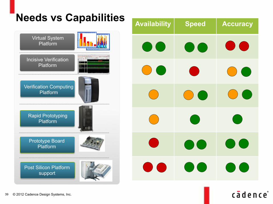
Needs vs Capabilities Rapid Prototyping
Platform Virtual System Platform
Incisive Verification Platform
Rapid Prototyping Platform
Verification Computing Platform
Prototype Board Platform
Post Silicon Platform support
Availability Speed Accuracy
39
© 2012 Cadence Design Systems, Inc.
• Challenges Integrating RTL and SW for Complex SoCs
• Integrated System Software Development – Xilinx Zynq-7000 Extensible Processing Platform
• HW-SW Verification – Metric Driven System Verification – SW Debug Capabilities – HW Debug Capabilities
• Conclusion
Agenda
40
© 2012 Cadence Design Systems, Inc.
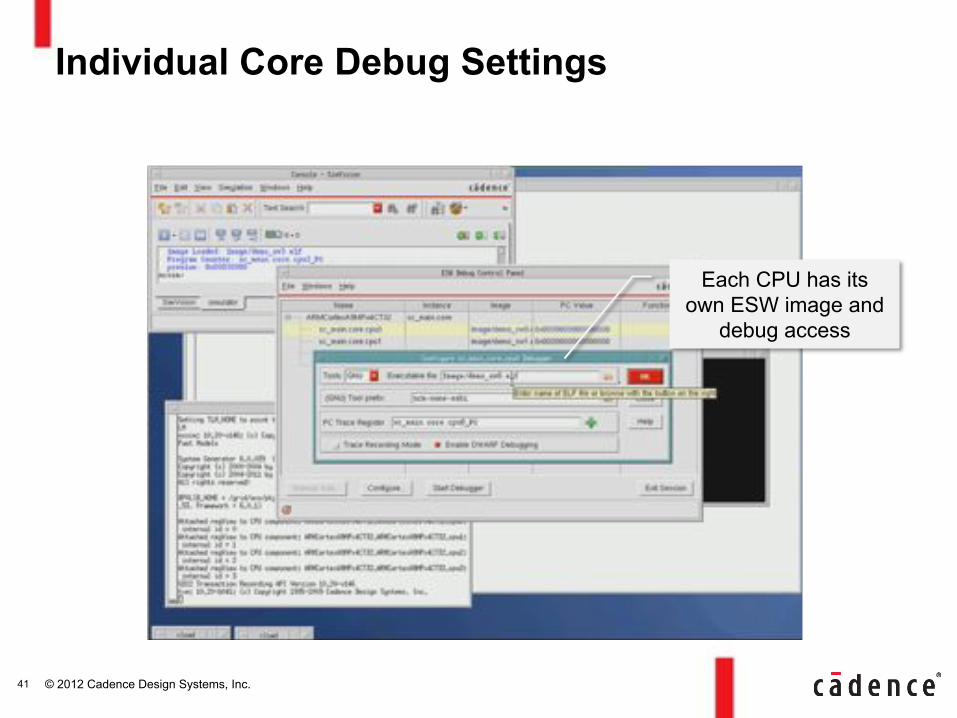
Individual Core Debug Settings
41
Each CPU has its own ESW image and
debug access
© 2012 Cadence Design Systems, Inc.
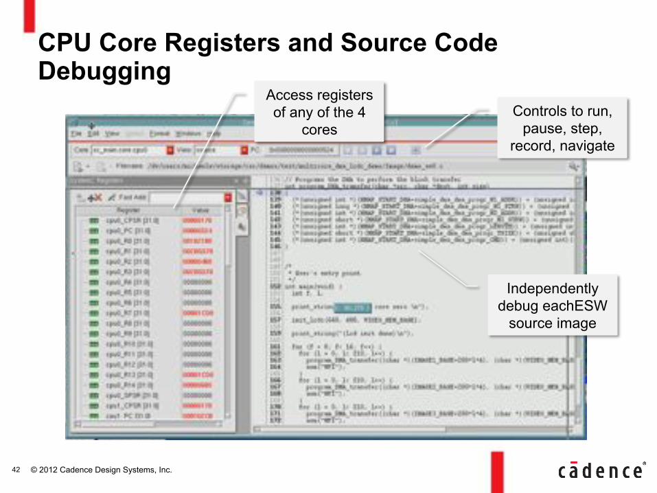
CPU Core Registers and Source Code Debugging
42
Independently debug eachESW
source image
Access registers of any of the 4
cores Controls to run,
pause, step, record, navigate
© 2012 Cadence Design Systems, Inc.
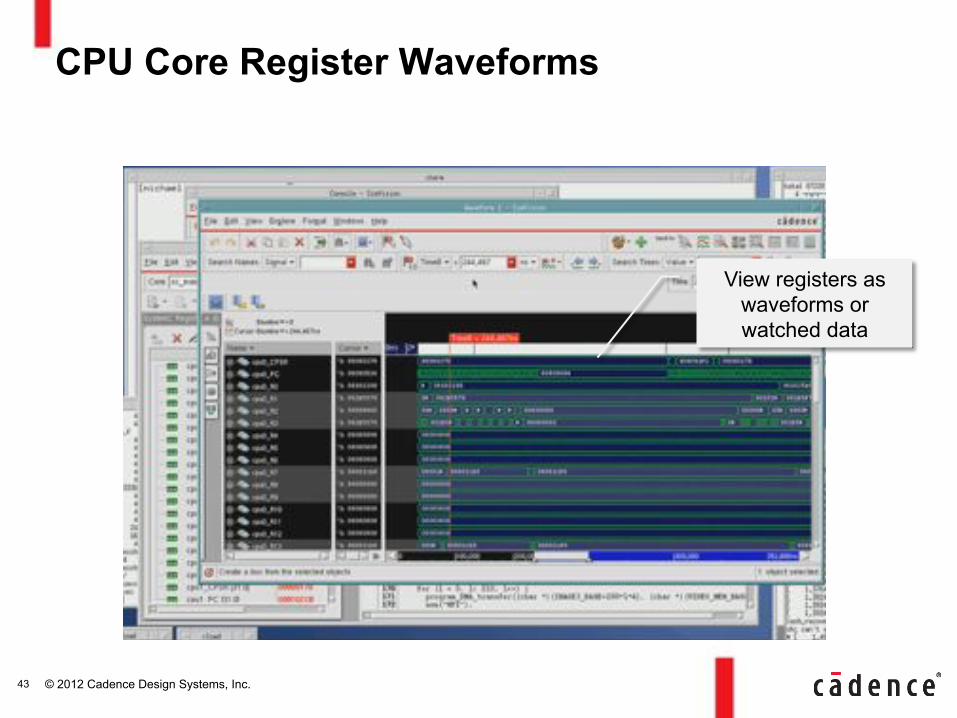
CPU Core Register Waveforms
43
View registers as waveforms or watched data
© 2012 Cadence Design Systems, Inc.
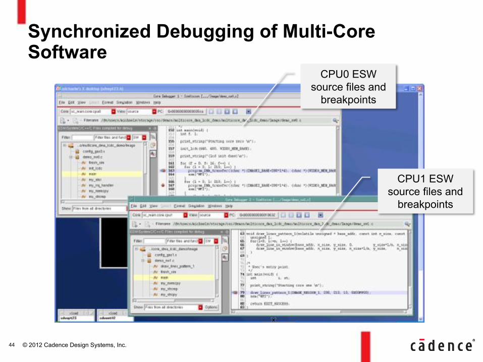
Synchronized Debugging of Multi-Core Software
44
CPU0 ESW source files and
breakpoints
CPU1 ESW source files and
breakpoints

© 2012 Cadence Design Systems, Inc.
Source Code and Register Waveform Views Kept in Sync for Moving Forward/Backward in Time
45
Waveforms, registers, and source all in sync
© 2012 Cadence Design Systems, Inc.
• Challenges Integrating RTL and SW for Complex SoCs
• Integrated System Software Development – Xilinx Zynq-7000 Extensible Processing Platform
• HW-SW Verification – Metric Driven System Verification – SW Debug Capabilities – HW Debug Capabilities
• Conclusion
Agenda
46
© 2012 Cadence Design Systems, Inc.
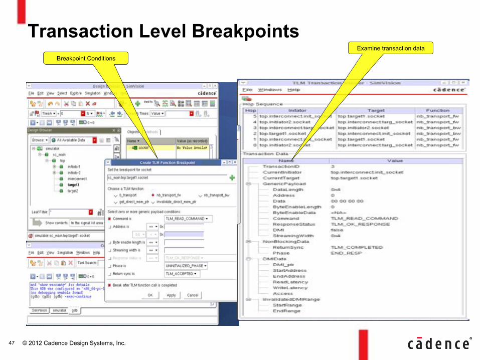
Transaction Level Breakpoints Breakpoint Conditions
Examine transaction data
47
© 2012 Cadence Design Systems, Inc.
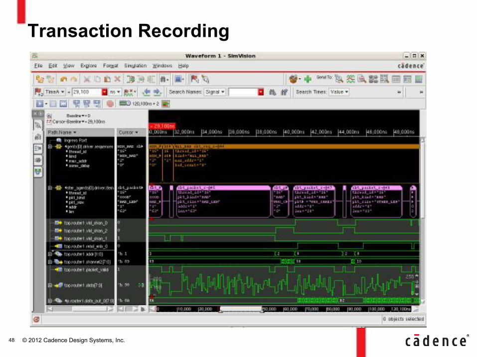
Transaction Recording
48
© 2012 Cadence Design Systems, Inc.
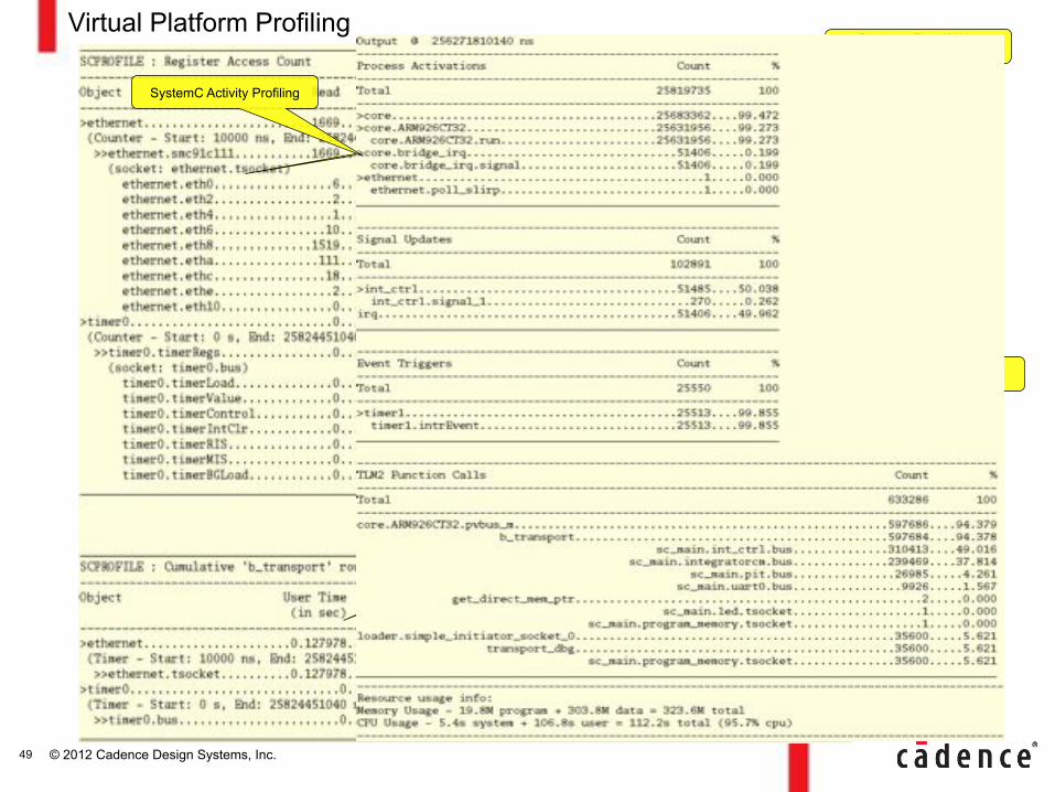
Virtual Platform Profiling Register Read/Write
Profiling
Measuring time spent in b_transport
SystemC Activity Profiling
49
© 2012 Cadence Design Systems, Inc.
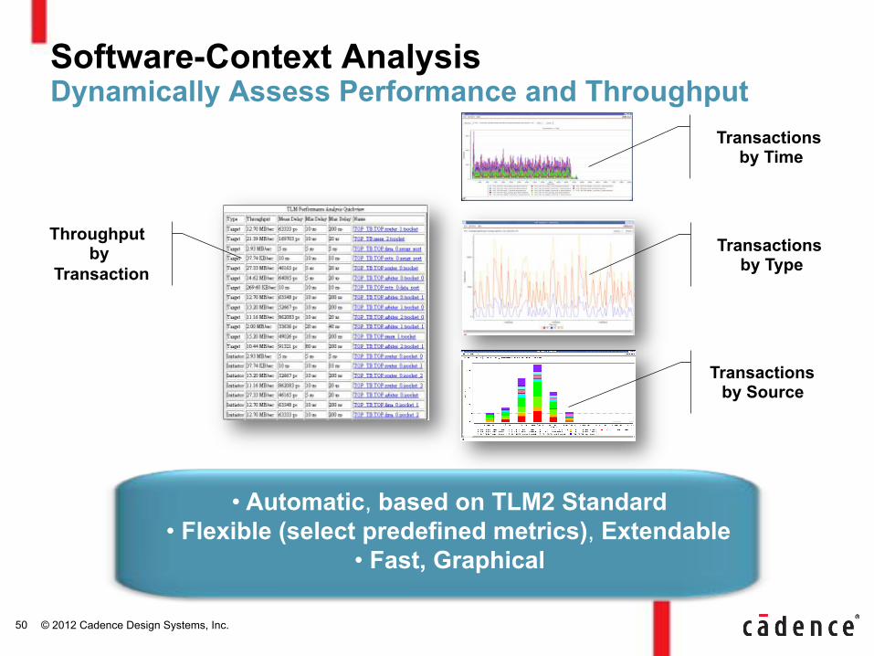
Software-Context Analysis Dynamically Assess Performance and Throughput
Transactions by Type
Transactions by Source
Throughput by
Transaction
50
• Automatic, based on TLM2 Standard • Flexible (select predefined metrics), Extendable
• Fast, Graphical
Transactions by Time
© 2012 Cadence Design Systems, Inc.
• Challenges Integrating RTL and SW for Complex SoCs
• Integrated System Software Development – Xilinx Zynq-7000 Extensible Processing Platform
• HW-SW Verification – Metric Driven System Verification – SW Debug Capabilities – HW Debug Capabilities
• Conclusion
Agenda
51
© 2012 Cadence Design Systems, Inc.
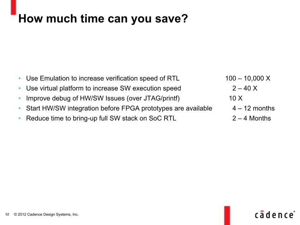
• Use Emulation to increase verification speed of RTL 100 – 10,000 X • Use virtual platform to increase SW execution speed 2 – 40 X • Improve debug of HW/SW Issues (over JTAG/printf) 10 X • Start HW/SW integration before FPGA prototypes are available 4 – 12 months • Reduce time to bring-up full SW stack on SoC RTL 2 – 4 Months
How much time can you save?
52
© 2012 Cadence Design Systems, Inc.
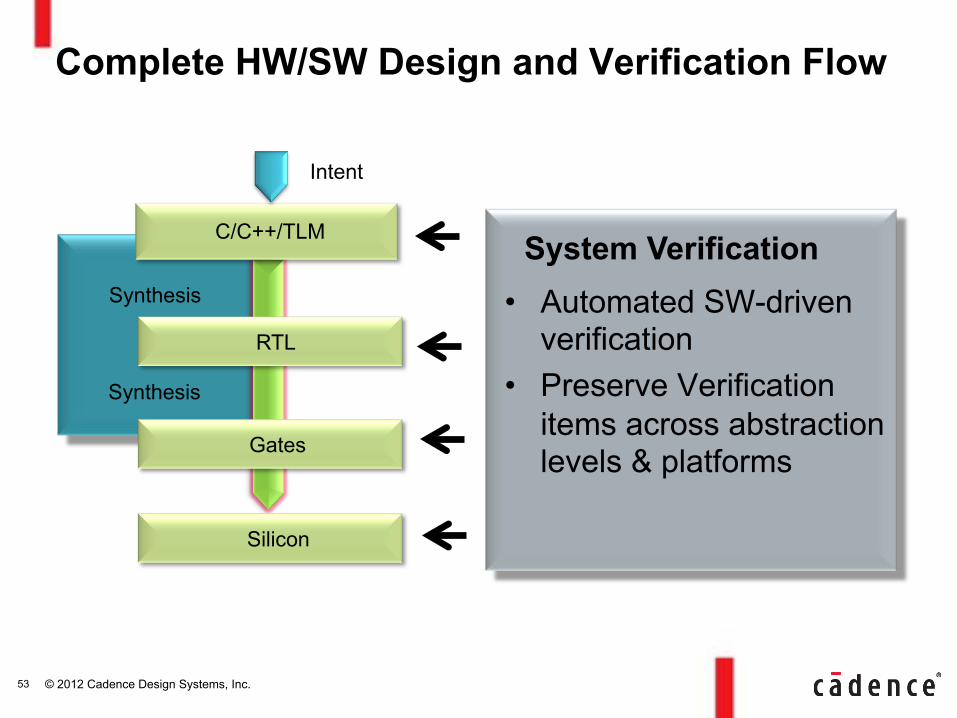
Synthesis
System Verification
Complete HW/SW Design and Verification Flow
RTL
Gates
Silicon
C/C++/TLM
Intent
• Automated SW-driven verification
• Preserve Verification items across abstraction levels & platforms
Synthesis
53
© 2012 Cadence Design Systems, Inc.
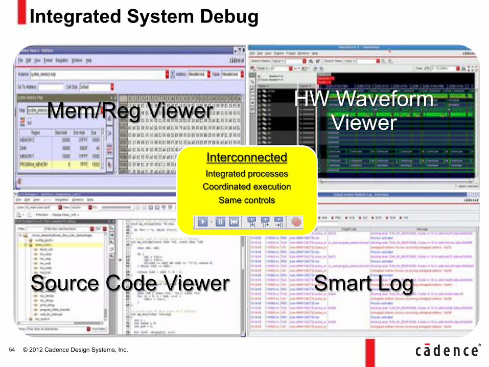
Integrated System Debug
54
Mem/Reg Viewer
HW Waveform
Viewer
Source Code Viewer Smart Log
Interconnected Integrated processes
Coordinated execution Same controls
© 2012 Cadence Design Systems, Inc.