Embed Size (px)
Citation preview
Describing Synthesizable RTLin SystemC™Version 1.2, November 2002

Printed in the U.S.A.
Describing Synthesizable RTL in SystemC™, v1.2
Trademarks and Copyright
Synopsys and CoCentric are a registered trademarks of Synopsys, Inc. with further information at http://synopsys.com.
SystemC is a trademark of Synopsys, Inc.
All other product or company names may be trademarks of their respective owners.
Copyright © 2001-2002 Synopsys, Inc.
iii
Contents
About This Guide. . . . . . . . . . . . . . . . . . . . . . . . . . . . . . . . . . . . . . . x
SystemC Training . . . . . . . . . . . . . . . . . . . . . . . . . . . . . . . . . . . . . . xi
Information About Synopsys SystemC Synthesis Products . . . . . . xii
1. SystemC RTL Synthesis Overview
System-Level Design . . . . . . . . . . . . . . . . . . . . . . . . . . . . . . . . . . . 1-2
System-Level Design Challenges . . . . . . . . . . . . . . . . . . . . . . . . . . 1-2
Component Integration . . . . . . . . . . . . . . . . . . . . . . . . . . . . . . . 1-2
Tool Interoperability . . . . . . . . . . . . . . . . . . . . . . . . . . . . . . . . . . 1-3
Design Team Collaboration . . . . . . . . . . . . . . . . . . . . . . . . . . . . 1-3
SystemC . . . . . . . . . . . . . . . . . . . . . . . . . . . . . . . . . . . . . . . . . . . . . 1-4
Why Synthesis From SystemC? . . . . . . . . . . . . . . . . . . . . . . . . . . . 1-5
Interpretation Errors . . . . . . . . . . . . . . . . . . . . . . . . . . . . . . . . . . 1-5
Verification Reuse . . . . . . . . . . . . . . . . . . . . . . . . . . . . . . . . . . . 1-6
Increased Productivity . . . . . . . . . . . . . . . . . . . . . . . . . . . . . . . . 1-6
About This Manual . . . . . . . . . . . . . . . . . . . . . . . . . . . . . . . . . . . . . 1-7

iv
2. Creating SystemC Modules for RTL Synthesis
Defining Modules and Processes . . . . . . . . . . . . . . . . . . . . . . . . . . 2-2
Modules . . . . . . . . . . . . . . . . . . . . . . . . . . . . . . . . . . . . . . . . . . . 2-2
Processes . . . . . . . . . . . . . . . . . . . . . . . . . . . . . . . . . . . . . . . . . 2-3Registering a Process . . . . . . . . . . . . . . . . . . . . . . . . . . . . . 2-3Triggering Execution of a Process . . . . . . . . . . . . . . . . . . . . 2-4Reading and Writing Processes . . . . . . . . . . . . . . . . . . . . . . 2-4Types of Processes . . . . . . . . . . . . . . . . . . . . . . . . . . . . . . . 2-4
Creating a Module . . . . . . . . . . . . . . . . . . . . . . . . . . . . . . . . . . . . . . 2-5
Module Header File . . . . . . . . . . . . . . . . . . . . . . . . . . . . . . . . . . 2-5Module Syntax . . . . . . . . . . . . . . . . . . . . . . . . . . . . . . . . . . . 2-6
Module Ports . . . . . . . . . . . . . . . . . . . . . . . . . . . . . . . . . . . . . . . 2-6Port Syntax. . . . . . . . . . . . . . . . . . . . . . . . . . . . . . . . . . . . . . 2-7Port Data Types . . . . . . . . . . . . . . . . . . . . . . . . . . . . . . . . . . 2-8
Signals . . . . . . . . . . . . . . . . . . . . . . . . . . . . . . . . . . . . . . . . . . . . 2-8Signal Syntax . . . . . . . . . . . . . . . . . . . . . . . . . . . . . . . . . . . . 2-9Signal Data Types . . . . . . . . . . . . . . . . . . . . . . . . . . . . . . . . 2-9
Data Member Variables . . . . . . . . . . . . . . . . . . . . . . . . . . . . . . . 2-10
Creating a Process in a Module. . . . . . . . . . . . . . . . . . . . . . . . . 2-11
Defining the Sensitivity List . . . . . . . . . . . . . . . . . . . . . . . . . . . . 2-12Defining a Level-Sensitive Process . . . . . . . . . . . . . . . . . . . 2-12Incomplete Sensitivity Lists . . . . . . . . . . . . . . . . . . . . . . . . . 2-13Defining an Edge-Sensitive Process . . . . . . . . . . . . . . . . . . 2-13Limitations for Sensitivity Lists . . . . . . . . . . . . . . . . . . . . . . . 2-14
Member Functions . . . . . . . . . . . . . . . . . . . . . . . . . . . . . . . . . . . 2-15
Module Constructor . . . . . . . . . . . . . . . . . . . . . . . . . . . . . . . . . . 2-15
Implementing the Module . . . . . . . . . . . . . . . . . . . . . . . . . . . . . 2-15
v
Reading and Writing Ports and Signals . . . . . . . . . . . . . . . . . . . 2-16
Reading and Writing Bits of Ports and Signals . . . . . . . . . . . . . 2-16
Signal and Port Assignments. . . . . . . . . . . . . . . . . . . . . . . . . . . 2-17
Variable Assignment . . . . . . . . . . . . . . . . . . . . . . . . . . . . . . . . . 2-18
Creating a Module With a Single SC_METHOD Process . . . . . . . . 2-20
Creating a Module With Multiple SC_METHOD Processes . . . . . . 2-22
Creating a Hierarchical RTL Module . . . . . . . . . . . . . . . . . . . . . . . . 2-26
The Basics of Hierarchical Module Creation . . . . . . . . . . . . . . . 2-26
Hierarchical RTL Module Example . . . . . . . . . . . . . . . . . . . . . . 2-28
3. Using the Synthesizable Subset
Converting to a Synthesizable Subset . . . . . . . . . . . . . . . . . . . . . . 3-2
SystemC and C++ Synthesizable Subsets . . . . . . . . . . . . . . . . 3-2Nonsynthesizable SystemC Constructs . . . . . . . . . . . . . . . . 3-3Nonsynthesizable C/C++ Constructs . . . . . . . . . . . . . . . . . . 3-4
Modifying Data for Synthesis. . . . . . . . . . . . . . . . . . . . . . . . . . . . . . 3-7
Synthesizable Data Types . . . . . . . . . . . . . . . . . . . . . . . . . . . . . 3-8
Nonsynthesizable Data Types . . . . . . . . . . . . . . . . . . . . . . . . . . 3-8
Recommended Data Types for Synthesis . . . . . . . . . . . . . . . . . 3-8
Using SystemC Data Types . . . . . . . . . . . . . . . . . . . . . . . . . . . . 3-12Bit Vector Data Type Operators . . . . . . . . . . . . . . . . . . . . . . 3-12Fixed and Arbitrary Precision Data Type Operators. . . . . . . 3-13
Using Enumerated Data Types . . . . . . . . . . . . . . . . . . . . . . . . . 3-14
Using Aggregate Data Types . . . . . . . . . . . . . . . . . . . . . . . . . . . 3-14
Using C++ Data Types. . . . . . . . . . . . . . . . . . . . . . . . . . . . . . . . 3-14
Data Members of a Module . . . . . . . . . . . . . . . . . . . . . . . . . . . . 3-15
vi
Recommendations About Modification for Synthesis . . . . . . . . . . . 3-17
4. RTL Coding Guidelines
Register Inference . . . . . . . . . . . . . . . . . . . . . . . . . . . . . . . . . . . . . . 4-2
Flip-Flop Inference. . . . . . . . . . . . . . . . . . . . . . . . . . . . . . . . . . . 4-2Simple D Flip-flop . . . . . . . . . . . . . . . . . . . . . . . . . . . . . . . . . 4-2D Flip-Flop With an Active-High Asynchronous Set
or Reset . . . . . . . . . . . . . . . . . . . . . . . . . . . . . . . . . . . . . 4-4D Flip-Flop With an Active-Low Asynchronous Set
or Reset . . . . . . . . . . . . . . . . . . . . . . . . . . . . . . . . . . . . . 4-5D Flip-Flop With Synchronous Set or Reset. . . . . . . . . . . . . 4-8Inferring JK Flip-Flops . . . . . . . . . . . . . . . . . . . . . . . . . . . . . 4-10Inferring Toggle Flip-Flops . . . . . . . . . . . . . . . . . . . . . . . . . . 4-13
Latch Inference . . . . . . . . . . . . . . . . . . . . . . . . . . . . . . . . . . . . . 4-16Inferring a D Latch From an If Statement . . . . . . . . . . . . . . . 4-16Inferring an SR Latch . . . . . . . . . . . . . . . . . . . . . . . . . . . . . . 4-17Avoiding Latch Inference . . . . . . . . . . . . . . . . . . . . . . . . . . . 4-19Inferring a Latch From a Switch Statement . . . . . . . . . . . . . 4-21Active-Low Set and Reset . . . . . . . . . . . . . . . . . . . . . . . . . . 4-25Active-High Set and Reset . . . . . . . . . . . . . . . . . . . . . . . . . . 4-26D Latch With an Asynchronous Set and Reset . . . . . . . . . . 4-28D Latch With an Asynchronous Set . . . . . . . . . . . . . . . . . . . 4-29D Latch With an Asynchronous Reset . . . . . . . . . . . . . . . . . 4-30
Three-State Inference . . . . . . . . . . . . . . . . . . . . . . . . . . . . . . . . . . . 4-31
Simple Three-State Inference . . . . . . . . . . . . . . . . . . . . . . . . . . 4-31
Three-State Driver for Bus . . . . . . . . . . . . . . . . . . . . . . . . . . . . . 4-33
Registered Three-State Drivers . . . . . . . . . . . . . . . . . . . . . . . . . 4-34
State Machines . . . . . . . . . . . . . . . . . . . . . . . . . . . . . . . . . . . . . . . . 4-38
vii
State Machine With a Common Computation Process . . . . . . . 4-40
State Machine With Separate Computation Processes . . . . . . . 4-42
Moore State Machine. . . . . . . . . . . . . . . . . . . . . . . . . . . . . . . . . 4-44
5. Behavioral Modeling and Synthesis
Comparing RTL and Behavioral Modeling. . . . . . . . . . . . . . . . . . . . 5-2
What is Behavioral Synthesis? . . . . . . . . . . . . . . . . . . . . . . . . . . . . 5-3
Timing . . . . . . . . . . . . . . . . . . . . . . . . . . . . . . . . . . . . . . . . . . . . 5-4
Scheduling . . . . . . . . . . . . . . . . . . . . . . . . . . . . . . . . . . . . . . . . . 5-5
Allocating Hardware. . . . . . . . . . . . . . . . . . . . . . . . . . . . . . . . . . 5-7
Creating the Data Path and Finite State Machine . . . . . . . . . . . 5-8
Choosing the Right Abstraction for Synthesis . . . . . . . . . . . . . . . . . 5-9
Identifying Attributes Suitable for RTL Synthesis. . . . . . . . . . . . 5-9
Identifying Attributes Suitable for Behavioral Synthesis. . . . . . . 5-10
Benefits of Behavioral Synthesis . . . . . . . . . . . . . . . . . . . . . . . . 5-11
RTL and Behavioral Coding Style Examples. . . . . . . . . . . . . . . . . . 5-12
RTL Coding Style. . . . . . . . . . . . . . . . . . . . . . . . . . . . . . . . . . . . 5-12
Behavioral Coding Style . . . . . . . . . . . . . . . . . . . . . . . . . . . . . . 5-16
Getting More Information About Behavioral Synthesis . . . . . . . . . . 5-18

viii
ix
Preface FIX ME!
This preface includes the following sections:
• About This Guide
• SystemC Training
• Information About Synopsys SystemC Synthesis Products

x
About This Guide
The Describing Synthesizable RTL in SystemC describes how to develop a SystemC RTL model for synthesis and introduces behavioral modeling and synthesis.
For information about SystemC, see the Open SystemC Community web site at http://www.systemc.org.
Related Publications
For information about the SystemC language and syntax, see the SystemC User’s Manual available from the Open SystemC Community web site at http://www.systemc.org.
Comments About This Document
E-mail your comments about this document to [email protected].
Typographical Conventions
Courier font is used in this document to distinguish SystemC code examples.
xi
SystemC Training
For information about SystemC training and private workshops, contact
• Willamette HDL
http://www.whdl.com
Three-day SystemC for High-Level Synthesis
Three-day Modeling With SystemC
• Transfer
http://www.transfer.nt
Three-day Modeling With SystemC
• Fraunhofer IIS-A
http://www.iis.fhg.de
Three-day SystemC Training Classes
• Doulos
Five-day Comprehensive SystemC Training Class
http://www.doulos.com
• Blue Pacific Computing
http://www.bluepc.com
Three-Day SystemC Workshop
xii
Information About Synopsys SystemC Synthesis Products
For information about Synopsys SystemC synthesis products, contact your local Synopsys sales representative or
1. Go to the Synopsys Web page at http://www.synopsys.com
2. In the Synopsys Products field, choose
CoCentric® SystemC™ Compiler

1-1
1SystemC RTL Synthesis Overview 1
This chapter describes how RTL synthesis from SystemC fits into the system-level design flow. It contains the following sections:
• System-Level Design
• System-Level Design Challenges
• SystemC
• Why Synthesis From SystemC?
1-2
SystemC RTL Synthesis Overview: System-Level Design
System-Level Design
System-level design involves specifying the system, verifying its functionality, and determining optimum system architecture by evaluating design alternatives. Today’s complex systems have significant software content and are integrated into a system on a chip (SoC).
System-level design can help with the growing complexity of both the hardware and software. An effective system-level design strategy minimizes late design iterations and increases design team productivity, which enables you to deliver a high quality product on time.
System-Level Design Challenges
Developing an effective system-level design strategy presents several challenges that can be solved by using SystemC.
Component Integration
Component reuse is a widely implemented strategy for handling complexity, but many of the components are provided from various sources.
Because component models are written in different languages and styles, integrating the models into the system design is often so difficult the system designers avoid doing it, eliminating the important task of specification and functional verification.
1-3
SystemC RTL Synthesis Overview: System-Level Design Challenges
Tool Interoperability
Although system modeling tools are available, each tool uses a proprietary model format, which makes a model developed for one tool unsuitable for use with another tool. This lack of tool interoperability and model compatibility also prevents using more than one tool in a design flow.
Design Team Collaboration
During system architecture design, designers choose the processor(s), bus, and peripherals, and decide what to implement in hardware and software. Effective architecture design requires participation of the hardware and software design teams for creating models and influencing architectural decisions, which is called hardware-software co-design. Furthermore, as the hardware and software design teams participate in architecture design concurrently, communication and consensus is reached early in the design cycle. The results of this collaboration must be validated and corrections can be made early in the design cycle. This prevents surprises when the hardware and software are integrated much later in the design cycle. To further complicate the situation, the system designers, hardware designers, and software engineers often apply different design languages. A common design language is needed to increase understanding, communication, and productivity, and to bring these teams together during the system architecture design phase.
1-4
SystemC RTL Synthesis Overview: SystemC
SystemC
SystemC is the foundation for design tools and methodologies that address the above mentioned system-level design challenges of tool interoperability, team communication, and component model creation and distribution.
SystemC is based on C++, the most popular language with system designers and software engineers. The SystemC classes add the necessary constructs to C++ for modeling systems and hardware at various levels of abstraction—from the abstract untimed models to cycle-accurate RTL models. The software content of the system can be written in C++, without the need for additional constructs.
SystemC, by itself, solves only a few of the system-level design challenges. You can use SystemC for creating an executable specification to verify the system functionality and architecture, but analysis and architecture design tools are needed and IP vendors need to provide SystemC models.
The power of SystemC is that it can be used as a common language by system designers, software engineers, and hardware designers. SystemC allows exchange of IP models, creation of an interoperable tool infrastructure, and development of a concept-to-implementation design methodology. The same benefits derived from the standardization of Verilog and VHDL in RTL design can now be achieved in the system design space with SystemC.
1-5
SystemC RTL Synthesis Overview: Why Synthesis From SystemC?
Why Synthesis From SystemC?
Hardware design has the well-established Verilog and VHDL hardware description languages with tools and design flows based on them. Why should you bother to understand how to use SystemC, a system design language, for hardware design and synthesis?
Consider a scenario where a system designer has created an architectural model of a SoC in SystemC and you are a hardware designer. The architectural model contains a variety of models, including processor models, abstract bus models, and peripheral models. The peripheral models capture the full functionality and interface of the peripherals, although at a high level of abstraction. This allows the system designer to hand you the peripheral models as an executable specification, along with written requirements for the area, speed, and power consumption for the peripherals.
Interpretation Errors
You need to implement the peripherals and verify the implementation in the context of the entire system. If you use a Verilog or VHDL synthesis tool, you need to rewrite the peripheral models in Verilog or VHDL, which is a time-consuming and error-prone process. Or you can synthesize the peripheral models from SystemC. Instead of throwing away the work done at the system level and recoding the design, you can take the abstract, non-synthesizable peripheral models and change them into synthesizable models.

1-6
SystemC RTL Synthesis Overview: Why Synthesis From SystemC?
Verification Reuse
As an added advantage, you can use the system-level verification environment to check the correctness of your implementation as you modify it.
Increased Productivity
If a hardware designer receives a SystemC executable specification, implementation from SystemC gives higher designer productivity than recoding it in Verilog or VHDL. Higher designer productivity comes from two sources—modifying the design is faster than recoding, and verifying a modified design is faster than verifying a recoded HDL design.
Modifying is faster than recoding, because hardware functionality is envisioned as either an algorithm or a finite state machine and data path, even if the description is abstract. Algorithmic models can be synthesized using behavioral synthesis techniques, and finite state machines and data paths can be synthesized by using RTL synthesis techniques. The primary modification tasks are staying within the synthesizable subset and adding the implementation details and the hardware structure that were not included in the abstract model. You can reduce the modification effort by ensuring that the system designer minimizes violations in the abstract model.
Verifying a modified SystemC design is faster than verifying a recoded HDL design, because modification changes fewer lines of code and has fewer opportunities to introduce interpretation mistakes. Therefore, you typically spend less time debugging and verifying the hardware design.
1-7
SystemC RTL Synthesis Overview: About This Manual
Design engineers can achieve greater productivity by modifying a SystemC executable specification. Design teams can fully deploy the productivity of system-level design by using a SystemC synthesis tool that supports both behavioral and RTL styles. This designer productivity improvement can reduce time-to-market.
About This Manual
As with VHDL and Verilog, SystemC has modeling rules and a synthesizable subset of those rules. This manual describes the modeling rules and synthesizable subset for describing RTL in SystemC, and it introduces you to behavioral modeling and synthesis.

1-8
SystemC RTL Synthesis Overview: About This Manual

2-1
2Creating SystemC Modules for RTL Synthesis 2
This chapter explains the SystemC and C/C++ language elements that are important for RTL synthesis. It contains the following sections:
• Defining Modules and Processes
• Creating a Module
• Creating a Module With a Single SC_METHOD Process
• Creating a Module With Multiple SC_METHOD Processes
• Creating a Hierarchical RTL Module
2-2
Creating SystemC Modules for RTL Synthesis: Defining Modules and Processes
Defining Modules and Processes
This modeling guide explains how to develop SystemC RTL modules for synthesis. It assumes that you are knowledgeable about the C/C++ language and the SystemC Class Library available from the Open SystemC Community Web site at http://www.systemc.org.
Modules
The basic building block in SystemC is the module. A SystemC module is a container in which processes and other modules are instantiated. A typical module can have
• Single or multiple RTL processes to specify combinational or sequential logic
• Multiple RTL modules to specify hierarchy
• One or more member functions that are called from within an instantiated process or module
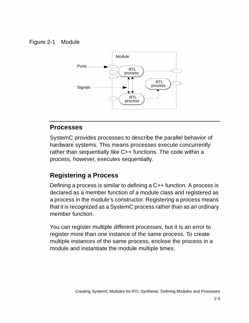
Figure 2-1 shows a module with several RTL processes. The processes within a module are concurrent, and they execute whenever one of their sensitive inputs changes.
2-3
Creating SystemC Modules for RTL Synthesis: Defining Modules and Processes
Figure 2-1 Module
Processes
SystemC provides processes to describe the parallel behavior of hardware systems. This means processes execute concurrently rather than sequentially like C++ functions. The code within a process, however, executes sequentially.
Registering a Process
Defining a process is similar to defining a C++ function. A process is declared as a member function of a module class and registered as a process in the module’s constructor. Registering a process means that it is recognized as a SystemC process rather than as an ordinary member function.
You can register multiple different processes, but it is an error to register more than one instance of the same process. To create multiple instances of the same process, enclose the process in a module and instantiate the module multiple times.
Module
RTLprocess
RTLprocess
RTLprocess
Ports
Signals

2-4
Creating SystemC Modules for RTL Synthesis: Defining Modules and Processes
Triggering Execution of a Process
You define a sensitivity list that identifies which input ports and signals trigger execution of the code within a process. You can define level-sensitive inputs to specify combinational logic or edge-sensitive inputs to specify sequential logic.
Reading and Writing Processes
A process can read from and write to ports, internal signals, and internal variables.
Processes use signals to communicate with each other. One process can cause another process to execute by assigning a new value to a signal that interconnects them. Do not use data variables for communication between processes, because the processes execute in random order and it can cause nondeterminism (order dependencies) during simulation.
Types of Processes
SystemC provides three process types—SC_METHOD, SC_CTHREAD, and SC_THREAD—that execute whenever their sensitive inputs change. For simulation, you can use any of the process types. For RTL synthesis, you can use only the SC_METHOD process.
The SC_METHOD process is sensitive to either changes in signal values (level-sensitive) or to particular transitions (edges) of the signal (edge-sensitive) and executes when one of its sensitive inputs changes.
2-5
Creating SystemC Modules for RTL Synthesis: Creating a Module
Creating a Module
It is a recommended coding practice to describe a module by using a separate header file (module_name.h) and an implementation file (module_name.cpp or module_name.cc).
Module Header File
Each module header file contains
• Port declarations
• Internal signal variable declarations
• Internal data variable declarations
• Process declarations
• Member function declarations
• Module constructor
2-6
Creating SystemC Modules for RTL Synthesis: Creating a Module
Module Syntax
Declare a module, using the syntax shown in bold in the following example:
#include "systemc.h"SC_MODULE (module_name) {
//Module port declarations//Signal variable declarations//Data variable declarations//Member function declarations//Method process declarations
//Module constructorSC_CTOR (module_name) {
//Register processes//Declare sensitivity list
}};
SC_MODULE and SC_CTOR are C++ macros defined in the SystemC Class library.
Module Ports
Each module has any number of input, outputs, and inout ports (see Figure 2-2), which determine the direction of data into or out of the module.
2-7
Creating SystemC Modules for RTL Synthesis: Creating a Module
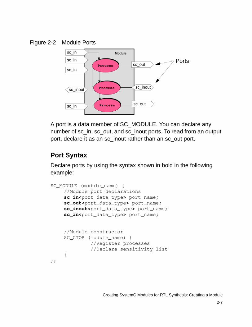
Figure 2-2 Module Ports
A port is a data member of SC_MODULE. You can declare any number of sc_in, sc_out, and sc_inout ports. To read from an output port, declare it as an sc_inout rather than an sc_out port.
Port Syntax
Declare ports by using the syntax shown in bold in the following example:
SC_MODULE (module_name) {//Module port declarationssc_in<port_data_type> port_name;sc_out<port_data_type> port_name;sc_inout<port_data_type> port_name;sc_in<port_data_type> port_name;
//Module constructorSC_CTOR (module_name) {
//Register processes//Declare sensitivity list
}};
Module
ProcessProcess
ProcessProcess
ProcessProcess
Portssc_in
sc_in
sc_outsc_in
sc_in sc_out
sc_inoutsc_inout
2-8
Creating SystemC Modules for RTL Synthesis: Creating a Module
Port Data Types
Ports connect to signals and have a data type associated with them. For synthesis, declare each port as one of the synthesizable data types described in “Converting to a Synthesizable Subset” on page 3-2.
Signals
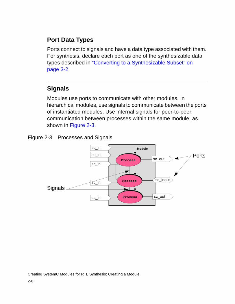
Modules use ports to communicate with other modules. In hierarchical modules, use signals to communicate between the ports of instantiated modules. Use internal signals for peer-to-peer communication between processes within the same module, as shown in Figure 2-3.
Figure 2-3 Processes and Signals
Module
ProcessProcess
ProcessProcess
ProcessProcess
Portssc_in
sc_in
sc_outsc_in
sc_in
sc_in
Signals
sc_out
sc_inout
2-9
Creating SystemC Modules for RTL Synthesis: Creating a Module
Signal Syntax
Declare signals by using the syntax shown in bold in the following example:
SC_MODULE (module_name) {//Module port declarationssc_in<port_type> port_name;sc_out<port_type> port_name;sc_in<port_type>port_name;
//Internal signal variable declarationssc_signal<signal_type> signal_name;sc_signal<signal_type> signal1, signal2;
//Data variable declarations//Process declarations//Member function declarations
//Module constructorSC_CTOR (module_name) {
//Register processes//Declare sensitivity list
}};
Signal Data Types
A signal’s bit-width is determined by its corresponding data type. Specify the data type as any of the synthesizable SystemC or C++ data types listed in “Converting to a Synthesizable Subset” on page 3-2. Signals and the ports they connect must have the same data types.
2-10
Creating SystemC Modules for RTL Synthesis: Creating a Module
Data Member Variables
Inside a module, you can define data member variables of any synthesizable SystemC or C++ type. These variables can be used for internal storage in the module. Recommendations about using data member variables for synthesis are provided in “Data Members of a Module” on page 3-15. Declare internal data variables by using the syntax shown in bold in the following example:
SC_MODULE (module_name) {//Module port declarationssc_in<port_type> port_name;sc_out<port_type> port_name;sc_in port_name;
//Internal signal variable declarationssc_signal<signal_type> signal_name;
//Data member variable declarationsint count_val; //Internal countersc_int<8> mem[1024]; //Array of sc_int
//Process declarations//Member function declaration
//Module constructorSC_CTOR (module_name) {
//Register processes//Declare sensitivity list
}};
Note: Do not use data variables for peer-to-peer communication in a module. This can cause pre- and post-synthesis simulation mismatches and nondeterminism (order dependency) in your design.

2-11
Creating SystemC Modules for RTL Synthesis: Creating a Module
Creating a Process in a Module
SystemC processes are declared in the module body and registered as processes inside the constructor of the module, as shown in bold in Example 2-1.
You must declare a process with a return type of void and no arguments, which is also shown in bold in Example 2-1.
To register a function as an SC_METHOD process, you need to use the SC_METHOD macro that is defined in the SystemC class library. The SC_METHOD macro takes one argument, the name of the process.
Example 2-1 Creating a Method Process in a Module
SC_MODULE(my_module){// Portssc_in<int> a;sc_in<bool> b;sc_out<int> x;sc_out<int> y;// Internal signalssc_signal<bool>c;sc_signal<int> d;// process declaration
void my_method_proc(); // module constructor SC_CTOR(my_module) {
// register process SC_METHOD(my_method_proc);
// Define the sensitivity list}
};
2-12
Creating SystemC Modules for RTL Synthesis: Creating a Module
Defining the Sensitivity List
An SC_METHOD process reacts to a set of signals called its sensitivity list. You can use the sensitive(), sensitive_pos(), or sensitive_neg() functions or the sensitive, sensitive_pos, or sensitive_neg streams in the sensitivity declaration list.
Defining a Level-Sensitive Process
For combinational logic, define a sensitivity list that includes all input ports, inout ports, and signals used as inputs to the process. Use the sensitive method to define the level-sensitive inputs. Example 2-2 shows in bold a stream-type declaration and a function-type declaration. Specify any number of sensitive inputs for the stream-type declaration, and specify only one sensitive input for the function-type declaration. You can call the sensitive function multiple times with different inputs.
Example 2-2 Defining a Level-Sensitive Sensitivity List
SC_MODULE(my_module){// Portssc_in<int> a;sc_in<bool> b;sc_out<int> x;sc_out<int> y;// Internal signalssc_signal<bool>c;sc_signal<int> d;sc_signal<int> e;// process declarationvoid my_method_proc();// module constructorSC_CTOR(my_module) {
// register processSC_METHOD(my_method_proc);// declare level-sensitive sensitivity listsensitive << a << c << d; // Stream declaration

2-13
Creating SystemC Modules for RTL Synthesis: Creating a Module
sensitive(b); //Function declarationsensitive(e); //Function declaration
}};
Incomplete Sensitivity Lists
To eliminate the risk of pre- and post-synthesis simulation mismatches, include all the inputs to the combinational logic process in the sensitivity list of the method process. Example 2-3 shows an incomplete sensitivity list.
Example 2-3 Incomplete Sensitivity List
//method process void comb_proc () { out_x = in_a & in_b & in_c; }
SC_CTOR( comb_logic_complete ) { // Register method process SC_METHOD( comb_proc); sensitive << in_a << in_b; // missing in_c }
Defining an Edge-Sensitive Process
For sequential logic, define a sensitivity list of the input ports and signals that trigger the process. Use the sensitive_pos, sensitive_neg, or both the sensitive_pos and sensitive_neg methods to define the edge-sensitive inputs that trigger the process. Declare ports and the edge-sensitive inputs as type sc_in<bool>. You can define any number of sc_in<bool> inputs.
2-14
Creating SystemC Modules for RTL Synthesis: Creating a Module
Define the sensitivity list by using either the function or the stream syntax. Example 2-4 shows in bold an example of a stream-type declaration for two inputs and a function-type declaration for the clock input.
Example 2-4 Defining an Edge-Sensitive Sensitivity List
SC_MODULE(my_module){// Portssc_in<int> a;sc_in<bool> b;sc_in<bool> clock;sc_out<int> x;sc_out<int> y;sc_in<bool> reset;// Internal signalssc_signal<bool>c;sc_signal<int> d;// process declarationvoid my_method_proc();// module constructorSC_CTOR(my_module) {
// register processSC_METHOD(my_method_proc);// declare sensitivity listsensitive_pos (clock); //Function delarationsensitive_neg << b << reset; // Stream declaration
}};
Limitations for Sensitivity Lists
When you define a sensitivity list, adhere to the following limitations:
• You cannot specify both edge-sensitive and level-sensitive inputs in the same process for synthesis.
• You cannot declare an sc_logic type for the clock or other edge-sensitive inputs. You can declare only an sc_in<bool> data type.
2-15
Creating SystemC Modules for RTL Synthesis: Creating a Module
Member Functions
You can declare member functions in a module that are not processes. This type of member function is not registered as a process in the module’s constructor. It can be called from a process. Member functions can contain any synthesizable C++ or SystemC statement allowed in a SC_METHOD process.
A member function that is not a process can return any synthesizable data type.
Module Constructor
For each module you need to create a constructor, which is used to
• Register processes
• Define a sensitivity list for an SC_METHOD process
For synthesis, other statements are not allowed in the constructor. See Example 2-4.
Implementing the Module
In the module implementation file, define the functionality of each SC_METHOD process and member function. Example 2-5 shows a minimal implementation file.
Example 2-5 Module Implementation File
#include "systemc.h"#include "my_module.h"void my_module::my_method_proc() { // describe process functionality as C++ code}
2-16
Creating SystemC Modules for RTL Synthesis: Creating a Module
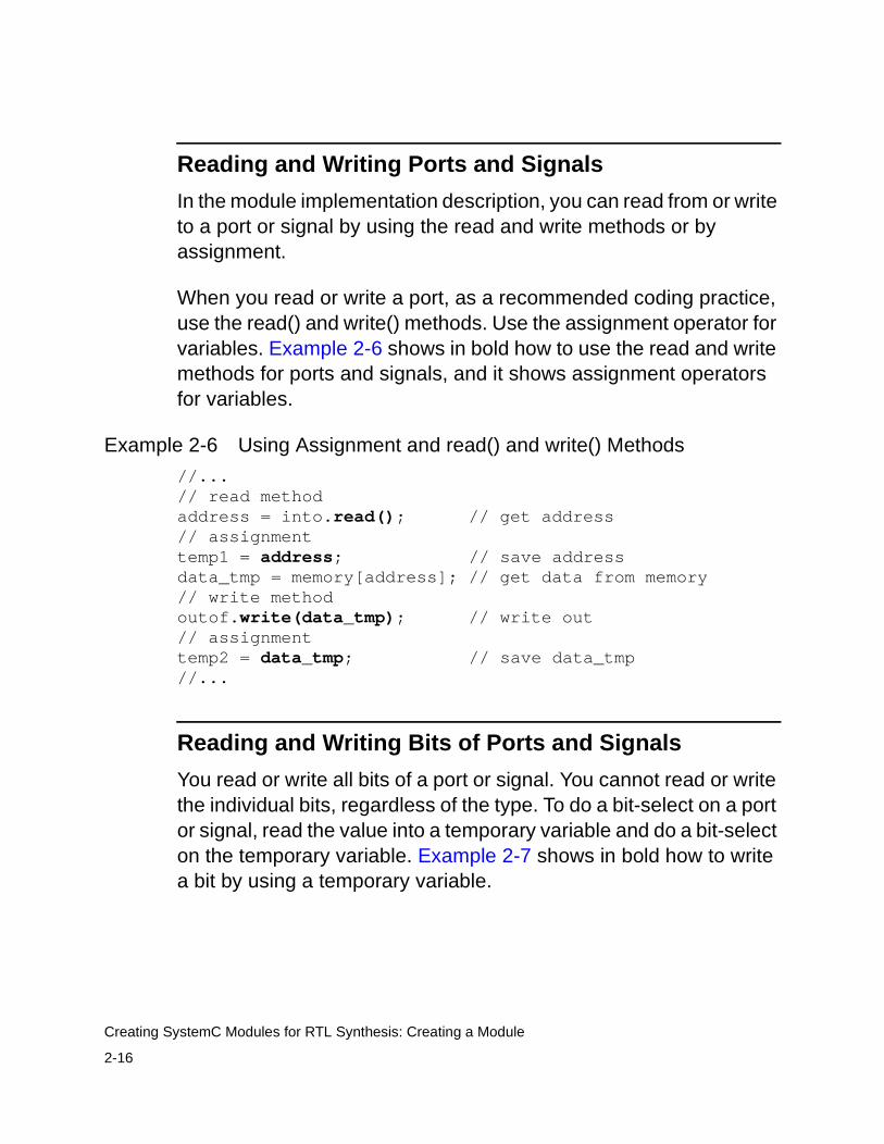
Reading and Writing Ports and Signals
In the module implementation description, you can read from or write to a port or signal by using the read and write methods or by assignment.
When you read or write a port, as a recommended coding practice, use the read() and write() methods. Use the assignment operator for variables. Example 2-6 shows in bold how to use the read and write methods for ports and signals, and it shows assignment operators for variables.
Example 2-6 Using Assignment and read() and write() Methods
//...// read methodaddress = into.read(); // get address// assignmenttemp1 = address; // save addressdata_tmp = memory[address]; // get data from memory// write methodoutof.write(data_tmp); // write out// assignmenttemp2 = data_tmp; // save data_tmp//...
Reading and Writing Bits of Ports and Signals
You read or write all bits of a port or signal. You cannot read or write the individual bits, regardless of the type. To do a bit-select on a port or signal, read the value into a temporary variable and do a bit-select on the temporary variable. Example 2-7 shows in bold how to write a bit by using a temporary variable.

2-17
Creating SystemC Modules for RTL Synthesis: Creating a Module
Example 2-7 Reading and Writing Bits of a Variable
//...sc_signal <sc_int<8> > a;sc_int<8> b;bool c;b = a.read();c = b[0];
// c = a[0]; /Does not work in SystemC
Example 2-7 reads the value of signal a into temporary variable b, and bit 0 of b is assigned to c. You cannot read a bit from signal a, because this operation is not allowed in SystemC.
Signal and Port Assignments
When you assign a value to a signal or port, the value on the right side is not transferred to the left side until the process ends. This means the signal value as seen by other processes is not updated immediately, but it is deferred.
Example 2-8 shows a serial register implementation with signal assignment, and Figure 2-4 shows the resulting schematic.
Example 2-8 Signal Assignment
#include "systemc.h"
SC_MODULE(rtl_nb) { sc_in<bool> clk; sc_in<bool> data; sc_inout<bool> regc, regd; void reg_proc() { regc.write(data.read()); regd.write(regc.read()); }

2-18
Creating SystemC Modules for RTL Synthesis: Creating a Module
SC_CTOR(rtl_nb) { SC_METHOD(reg_proc); sensitive_pos << clk; }};
Figure 2-4 Signal Assignment Schematic
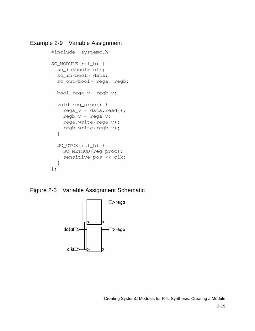
Variable Assignment
When you assign a value to a variable, the value on the right side is immediately transferred to the left side of the assignment statement.
Example 2-9 uses a variable assignment, where the implementation assigns the value of data to rega and regb, as the resulting schematic in Figure 2-5 indicates.
Note: This example is only an illustration of variable assignment. You can write the same behavior more efficiently by removing the rega_v and regb_v variables and writing the ports directly.
2-19
Creating SystemC Modules for RTL Synthesis: Creating a Module
Example 2-9 Variable Assignment
#include "systemc.h"
SC_MODULE(rtl_b) { sc_in<bool> clk; sc_in<bool> data; sc_out<bool> rega, regb; bool rega_v, regb_v; void reg_proc() { rega_v = data.read(); regb_v = rega_v; rega.write(rega_v); regb.write(regb_v); } SC_CTOR(rtl_b) { SC_METHOD(reg_proc); sensitive_pos << clk; }};
Figure 2-5 Variable Assignment Schematic
2-20
Creating SystemC Modules for RTL Synthesis: Creating a Module With a Single SC_METHOD Process
Creating a Module With a Single SC_METHOD Process
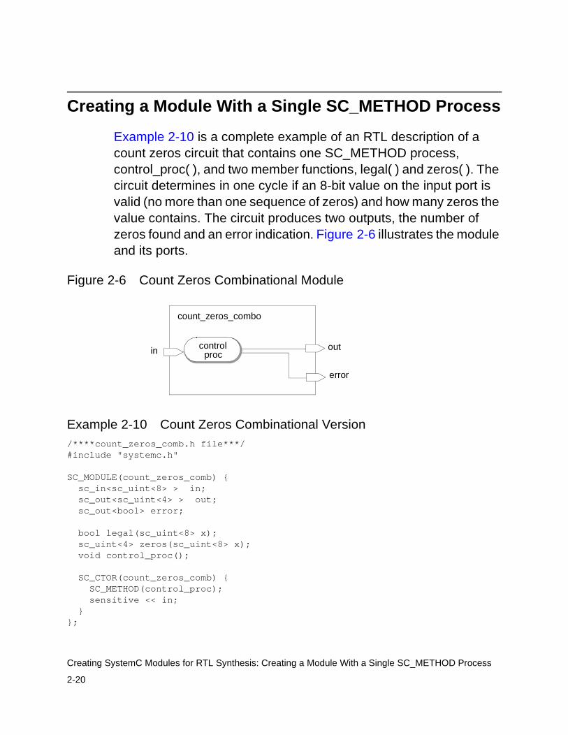
Example 2-10 is a complete example of an RTL description of a count zeros circuit that contains one SC_METHOD process, control_proc( ), and two member functions, legal( ) and zeros( ). The circuit determines in one cycle if an 8-bit value on the input port is valid (no more than one sequence of zeros) and how many zeros the value contains. The circuit produces two outputs, the number of zeros found and an error indication. Figure 2-6 illustrates the module and its ports.
Figure 2-6 Count Zeros Combinational Module
Example 2-10 Count Zeros Combinational Version/****count_zeros_comb.h file***/#include "systemc.h"
SC_MODULE(count_zeros_comb) { sc_in<sc_uint<8> > in; sc_out<sc_uint<4> > out; sc_out<bool> error; bool legal(sc_uint<8> x); sc_uint<4> zeros(sc_uint<8> x); void control_proc(); SC_CTOR(count_zeros_comb) { SC_METHOD(control_proc); sensitive << in; }};
count_zeros_combo
out
error
in controlproc
2-21
Creating SystemC Modules for RTL Synthesis: Creating a Module With a Single SC_METHOD Process
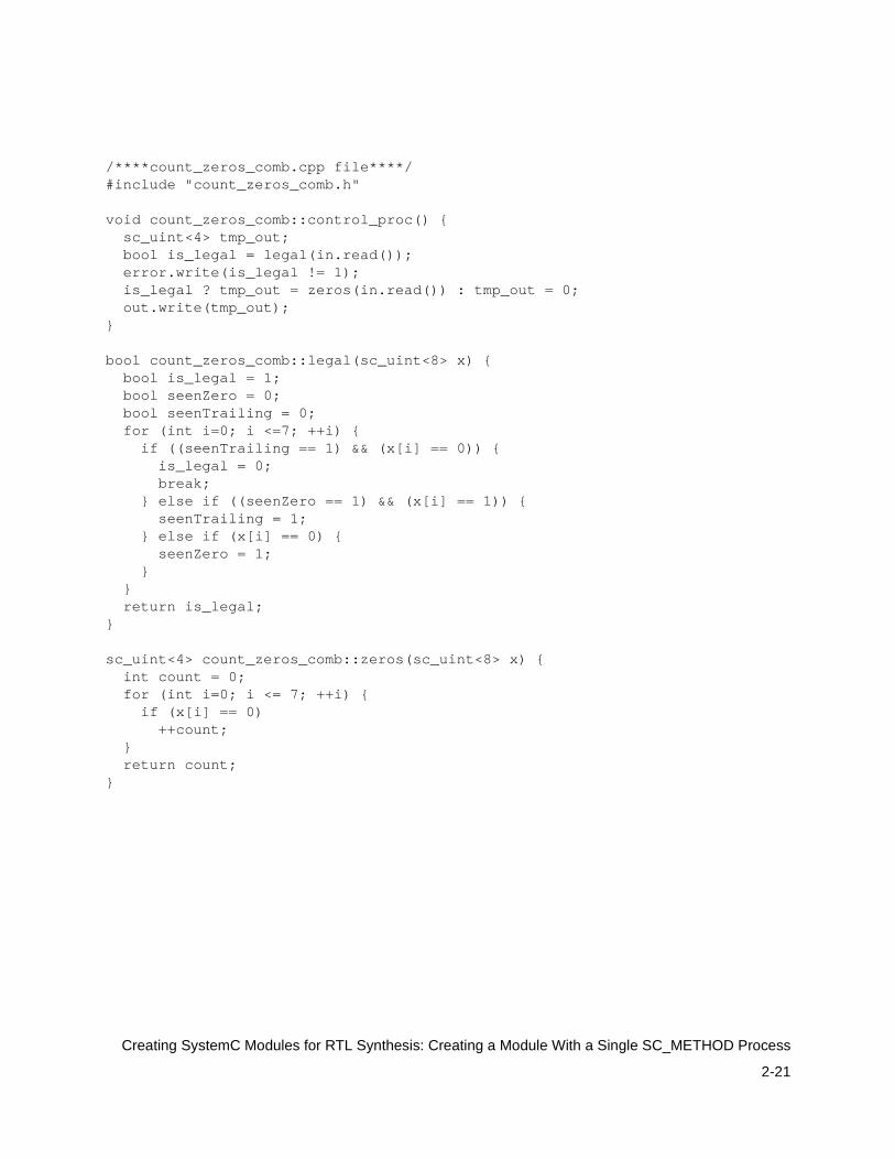
/****count_zeros_comb.cpp file****/#include "count_zeros_comb.h"
void count_zeros_comb::control_proc() { sc_uint<4> tmp_out; bool is_legal = legal(in.read()); error.write(is_legal != 1); is_legal ? tmp_out = zeros(in.read()) : tmp_out = 0; out.write(tmp_out);}
bool count_zeros_comb::legal(sc_uint<8> x) { bool is_legal = 1; bool seenZero = 0; bool seenTrailing = 0; for (int i=0; i <=7; ++i) { if ((seenTrailing == 1) && (x[i] == 0)) { is_legal = 0; break; } else if ((seenZero == 1) && (x[i] == 1)) { seenTrailing = 1; } else if (x[i] == 0) { seenZero = 1; } } return is_legal;}
sc_uint<4> count_zeros_comb::zeros(sc_uint<8> x) { int count = 0; for (int i=0; i <= 7; ++i) { if (x[i] == 0) ++count; } return count;}
2-22
Creating SystemC Modules for RTL Synthesis: Creating a Module With Multiple SC_METHOD Processes
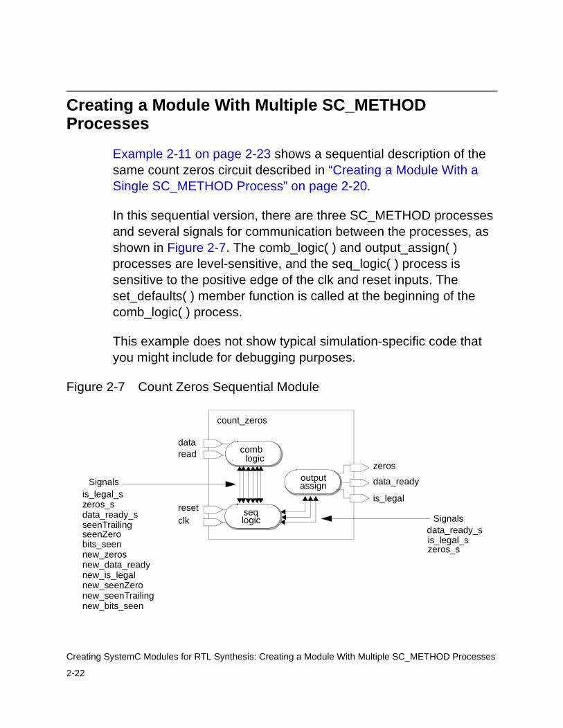
Creating a Module With Multiple SC_METHOD Processes
Example 2-11 on page 2-23 shows a sequential description of the same count zeros circuit described in “Creating a Module With a Single SC_METHOD Process” on page 2-20.
In this sequential version, there are three SC_METHOD processes and several signals for communication between the processes, as shown in Figure 2-7. The comb_logic( ) and output_assign( ) processes are level-sensitive, and the seq_logic( ) process is sensitive to the positive edge of the clk and reset inputs. The set_defaults( ) member function is called at the beginning of the comb_logic( ) process.
This example does not show typical simulation-specific code that you might include for debugging purposes.
Figure 2-7 Count Zeros Sequential Module
count_zeros
seqlogic
outputassign
dataread
resetclk
zeros
data_ready
is_legal
comblogic
Signalsis_legal_s
seenTrailingseenZero
zeros_sbits_seennew_zeros
Signalsdata_ready_sis_legal_s
new_data_readynew_is_legalnew_seenZeronew_seenTrailingnew_bits_seen
zeros_sdata_ready_s
2-23
Creating SystemC Modules for RTL Synthesis: Creating a Module With Multiple SC_METHOD Processes
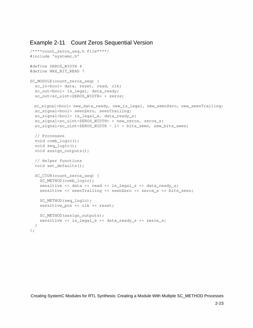
Example 2-11 Count Zeros Sequential Version/****count_zeros_seq.h file****/#include "systemc.h"
#define ZEROS_WIDTH 4#define MAX_BIT_READ 7
SC_MODULE(count_zeros_seq) { sc_in<bool> data, reset, read, clk; sc_out<bool> is_legal, data_ready; sc_out<sc_uint<ZEROS_WIDTH> > zeros; sc_signal<bool> new_data_ready, new_is_legal, new_seenZero, new_seenTrailing; sc_signal<bool> seenZero, seenTrailing; sc_signal<bool> is_legal_s, data_ready_s; sc_signal<sc_uint<ZEROS_WIDTH> > new_zeros, zeros_s; sc_signal<sc_uint<ZEROS_WIDTH - 1> > bits_seen, new_bits_seen; // Processes void comb_logic(); void seq_logic(); void assign_outputs(); // Helper functions void set_defaults(); SC_CTOR(count_zeros_seq) { SC_METHOD(comb_logic); sensitive << data << read << is_legal_s << data_ready_s; sensitive << seenTrailing << seenZero << zeros_s << bits_seen; SC_METHOD(seq_logic); sensitive_pos << clk << reset; SC_METHOD(assign_outputs); sensitive << is_legal_s << data_ready_s << zeros_s; }};
2-24
Creating SystemC Modules for RTL Synthesis: Creating a Module With Multiple SC_METHOD Processes
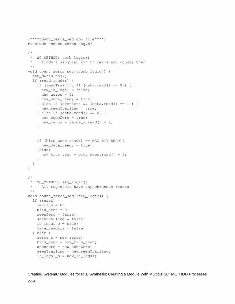
/****count_zeros_seq.cpp file****/#include "count_zeros_seq.h"
/* * SC_METHOD: comb_logic() * finds a singular run of zeros and counts them */void count_zeros_seq::comb_logic() { set_defaults(); if (read.read()) { if (seenTrailing && (data.read() == 0)) { new_is_legal = false; new_zeros = 0; new_data_ready = true; } else if (seenZero && (data.read() == 1)) { new_seenTrailing = true; } else if (data.read() == 0) { new_seenZero = true; new_zeros = zeros_s.read() + 1; } if (bits_seen.read() == MAX_BIT_READ){ new_data_ready = true; }else{ new_bits_seen = bits_seen.read() + 1; } } }
/* * SC_METHOD: seq_logic() * All registers have asynchronous resets */void count_zeros_seq::seq_logic() { if (reset) { zeros_s = 0; bits_seen = 0; seenZero = false; seenTrailing = false; is_legal_s = true; data_ready_s = false; } else { zeros_s = new_zeros; bits_seen = new_bits_seen; seenZero = new_seenZero; seenTrailing = new_seenTrailing; is_legal_s = new_is_legal;
2-25
Creating SystemC Modules for RTL Synthesis: Creating a Module With Multiple SC_METHOD Processes
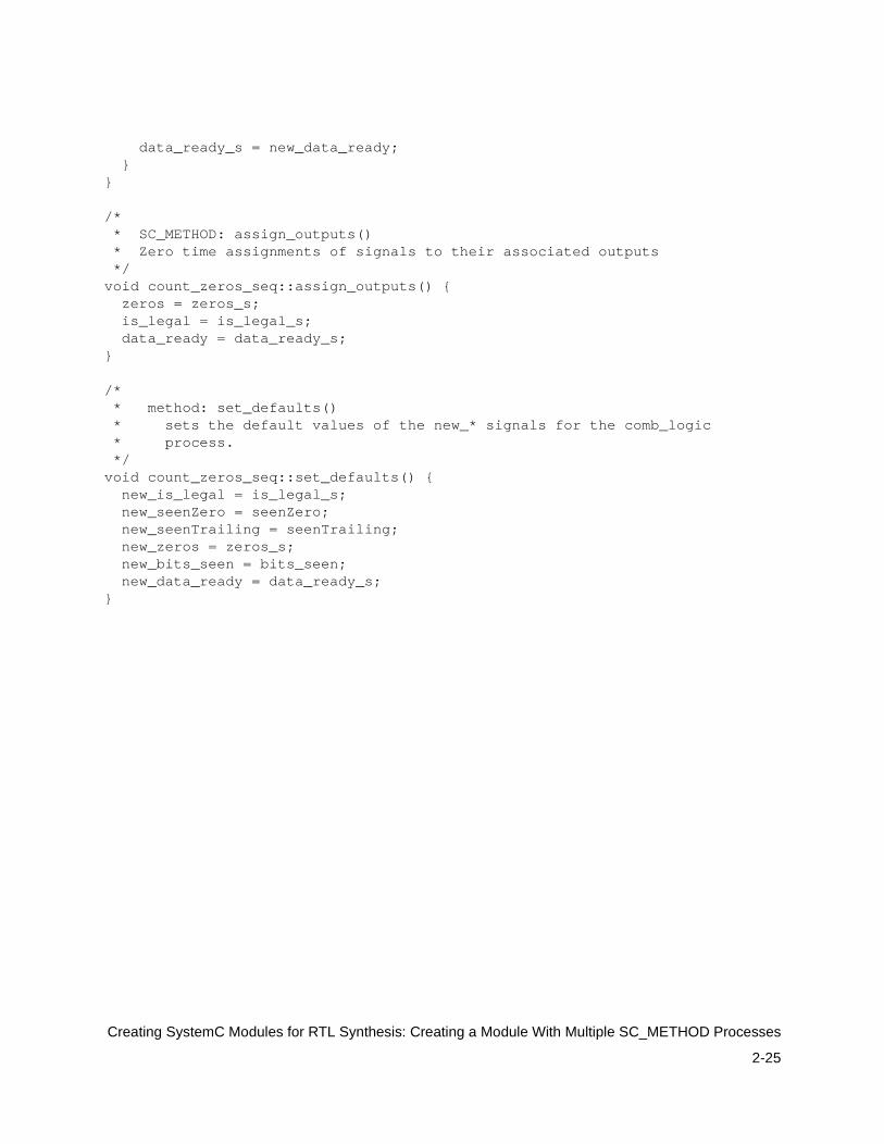
data_ready_s = new_data_ready; }}
/* * SC_METHOD: assign_outputs() * Zero time assignments of signals to their associated outputs */void count_zeros_seq::assign_outputs() { zeros = zeros_s; is_legal = is_legal_s; data_ready = data_ready_s;}
/* * method: set_defaults() * sets the default values of the new_* signals for the comb_logic * process. */void count_zeros_seq::set_defaults() { new_is_legal = is_legal_s; new_seenZero = seenZero; new_seenTrailing = seenTrailing; new_zeros = zeros_s; new_bits_seen = bits_seen; new_data_ready = data_ready_s;}
2-26
Creating SystemC Modules for RTL Synthesis: Creating a Hierarchical RTL Module
Creating a Hierarchical RTL Module
You can create a hierarchical module with multiple instantiated modules.
The Basics of Hierarchical Module Creation
To create a hierarchical module,
1. Create data members in the top-level module that are pointers to the instantiated modules.
2. Allocate the instantiated modules inside the constructor of the top-level module, giving each instance a unique name.
3. Bind the ports of the instantiated modules to the ports or signals of the top-level module. Use either binding by position or binding by name coding style, which is illustrated in bold in Example 2-12.
Example 2-12 shows the partial source code of two modules, fir_fsm and fir_data, instantiated within the fir_top module. The relevant code is highlighted in bold.
Example 2-12 Hierarchical Module With Multiple RTL Modules
/****fir_top.h****/#include <systemc.h>#include "fir_fsm.h"#include "fir_data.h"
SC_MODULE(fir_top) {
sc_in_clk CLK; sc_in<bool> RESET; sc_in<bool> IN_VALID; sc_in<int> SAMPLE;
2-27
Creating SystemC Modules for RTL Synthesis: Creating a Hierarchical RTL Module
sc_out<bool> OUTPUT_DATA_READY; sc_out<int> RESULT;
sc_signal<unsigned> state_out; //Communication between //two peer modules
// Create data members - pointers to instantiated // modules fir_fsm *fir_fsm1; fir_data *fir_data1; SC_CTOR(fir_top) {
// Create new instance of fir_fsm module fir_fsm1 = new fir_fsm("FirFSM");
// Binding by name fir_fsm1->clock(CLK); fir_fsm1->reset(RESET); fir_fsm1->in_valid(IN_VALID); fir_fsm1->state_out(state_out);
// Binding by position alternative//fir_fsm1 (CLK, RESET, IN_VALID, state_out);
// Create new instance // of fir_data module and bind by name
fir_data1 = new fir_data("FirData"); fir_data1->reset(RESET); fir_data1->state_out(state_out); fir_data1->sample(SAMPLE); fir_data1->result(RESULT); fir_data1->output_data_ready(OUTPUT_DATA_READY); fir_data1->clk(CLK);
... }};
/****fir_fsm.h****/SC_MODULE(fir_fsm) {
sc_in<bool> clock; sc_in<bool> reset; sc_in<bool> in_valid;
2-28
Creating SystemC Modules for RTL Synthesis: Creating a Hierarchical RTL Module
sc_out<unsigned> state_out;...
/****fir_data.h****/SC_MODULE(fir_data) { sc_in<bool> clk; sc_in<bool> reset; sc_in<unsigned> state_out; sc_in<int> sample; sc_out<int> result; sc_out<bool> output_data_ready;
...
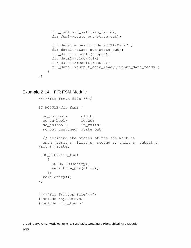
Hierarchical RTL Module Example
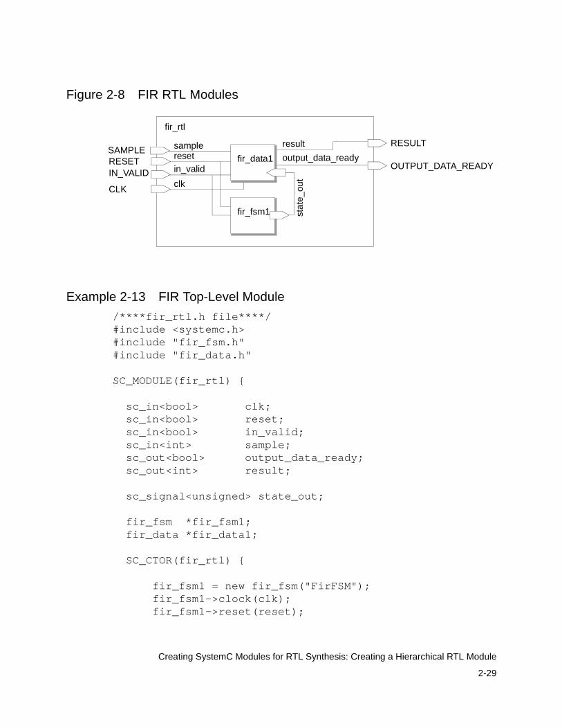
Example 2-13 on page 2-29 shows a complete example of the hierarchical RTL finite impulse response (FIR) filter description. This is a typical sequential logic description that separates the controlling FSM (Example 2-14 on page 2-30) and the data path (Example 2-15 on page 2-32) into two separate modules. Figure 2-8 illustrates the modules, the port binding, and their interconnecting signals.
In the top-level fir_rtl module, data member pointers to the fir_fsm and fir_data modules are declared, new instances of the two modules (fir_fsm1 and fir_data1) are created, and the port bindings are defined. A signal, state_out, is defined to connect the fir_fsm1 and fir_data1 state_out ports.
Coding guidelines for state machines are described in “State Machines” on page 4-38.
2-29
Creating SystemC Modules for RTL Synthesis: Creating a Hierarchical RTL Module
Figure 2-8 FIR RTL Modules
Example 2-13 FIR Top-Level Module
/****fir_rtl.h file****/#include <systemc.h>#include "fir_fsm.h"#include "fir_data.h"
SC_MODULE(fir_rtl) {
sc_in<bool> clk; sc_in<bool> reset; sc_in<bool> in_valid; sc_in<int> sample; sc_out<bool> output_data_ready; sc_out<int> result;
sc_signal<unsigned> state_out; fir_fsm *fir_fsm1; fir_data *fir_data1;
SC_CTOR(fir_rtl) {
fir_fsm1 = new fir_fsm("FirFSM"); fir_fsm1->clock(clk); fir_fsm1->reset(reset);
fir_rtl
RESETIN_VALID
SAMPLE
CLK
RESULT
OUTPUT_DATA_READY
fir_fsm1 stat
e_ou
t
sampleresetin_valid
clk
result
output_data_readyfir_data1
2-30
Creating SystemC Modules for RTL Synthesis: Creating a Hierarchical RTL Module
fir_fsm1->in_valid(in_valid); fir_fsm1->state_out(state_out);
fir_data1 = new fir_data("FirData"); fir_data1->state_out(state_out); fir_data1->sample(sample); fir_data1->clock(clk); fir_data1->result(result); fir_data1->output_data_ready(output_data_ready); }};
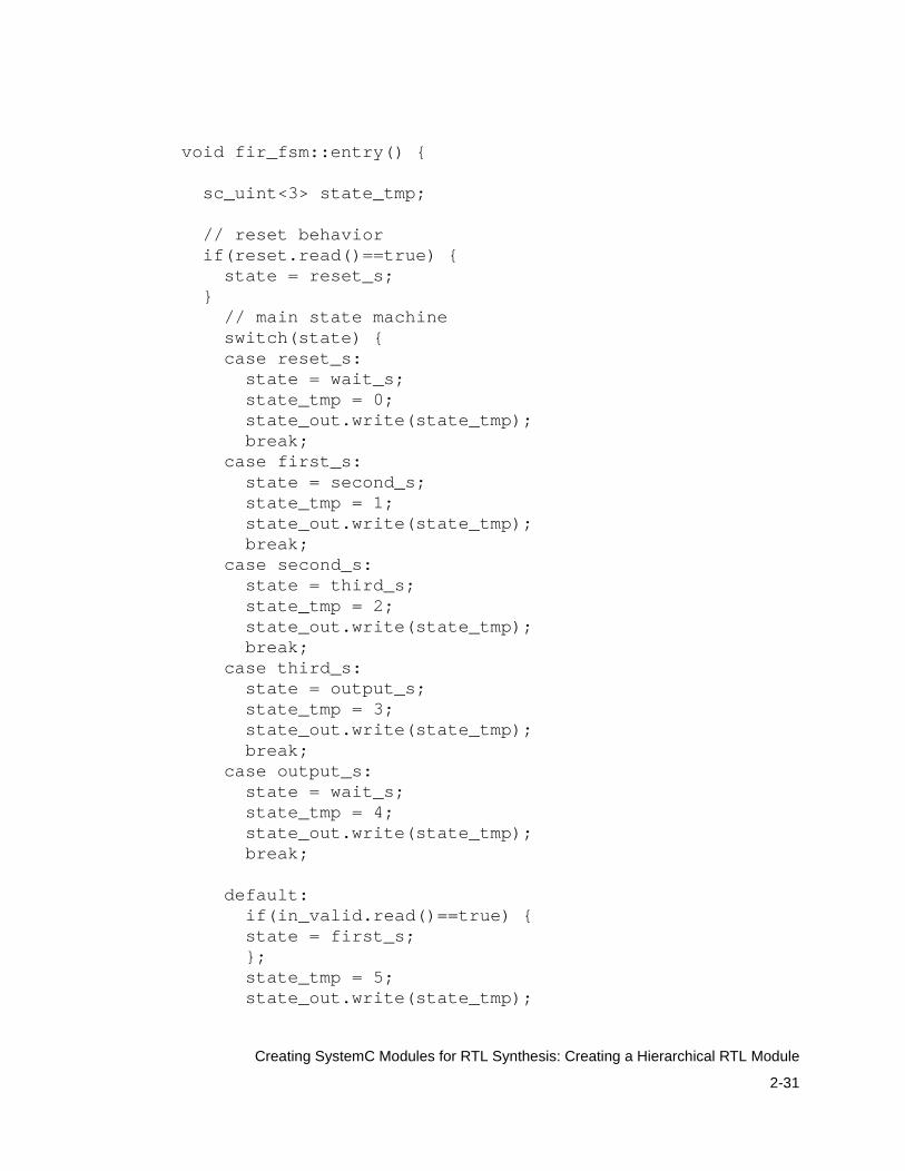
Example 2-14 FIR FSM Module
/****fir_fsm.h file****/
SC_MODULE(fir_fsm) {
sc_in<bool> clock; sc_in<bool> reset; sc_in<bool> in_valid; sc_out<unsigned> state_out;
// defining the states of the ste machine enum {reset_s, first_s, second_s, third_s, output_s, wait_s} state;
SC_CTOR(fir_fsm) { SC_METHOD(entry); sensitive_pos(clock); }; void entry();};
/****fir_fsm.cpp file****/#include <systemc.h>#include "fir_fsm.h"
2-31
Creating SystemC Modules for RTL Synthesis: Creating a Hierarchical RTL Module
void fir_fsm::entry() {
sc_uint<3> state_tmp;
// reset behavior if(reset.read()==true) { state = reset_s; } // main state machine switch(state) { case reset_s: state = wait_s; state_tmp = 0; state_out.write(state_tmp); break; case first_s: state = second_s; state_tmp = 1; state_out.write(state_tmp); break; case second_s: state = third_s; state_tmp = 2; state_out.write(state_tmp); break; case third_s: state = output_s; state_tmp = 3; state_out.write(state_tmp); break; case output_s: state = wait_s; state_tmp = 4; state_out.write(state_tmp); break; default: if(in_valid.read()==true) { state = first_s; }; state_tmp = 5; state_out.write(state_tmp);
2-32
Creating SystemC Modules for RTL Synthesis: Creating a Hierarchical RTL Module
break; } }
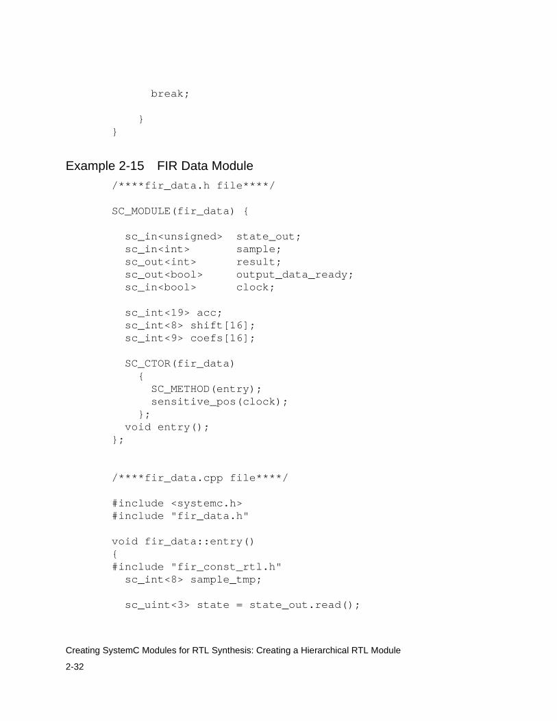
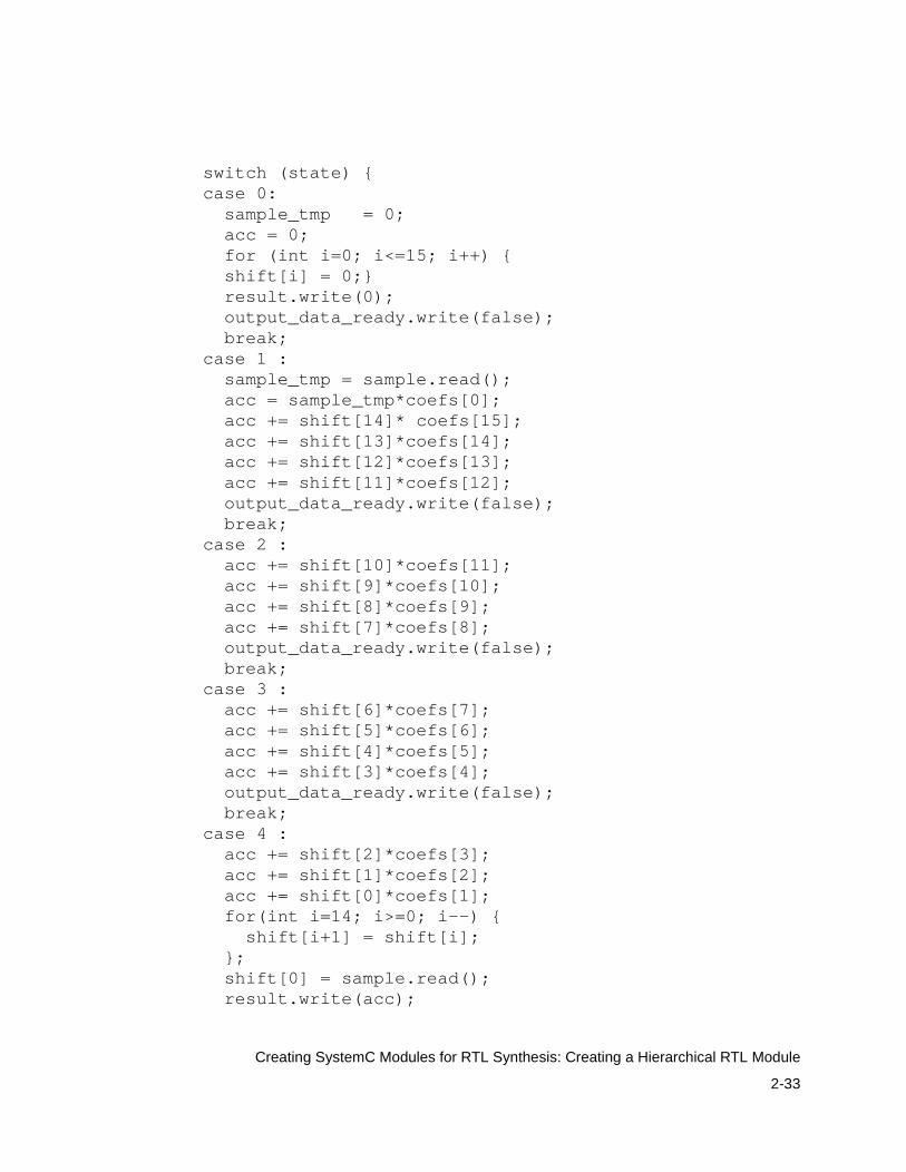
Example 2-15 FIR Data Module
/****fir_data.h file****/
SC_MODULE(fir_data) { sc_in<unsigned> state_out; sc_in<int> sample; sc_out<int> result; sc_out<bool> output_data_ready; sc_in<bool> clock; sc_int<19> acc; sc_int<8> shift[16]; sc_int<9> coefs[16];
SC_CTOR(fir_data) { SC_METHOD(entry); sensitive_pos(clock); }; void entry();};
/****fir_data.cpp file****/ #include <systemc.h>#include "fir_data.h"
void fir_data::entry(){#include "fir_const_rtl.h" sc_int<8> sample_tmp; sc_uint<3> state = state_out.read();
2-33
Creating SystemC Modules for RTL Synthesis: Creating a Hierarchical RTL Module
switch (state) { case 0: sample_tmp = 0; acc = 0; for (int i=0; i<=15; i++) { shift[i] = 0;} result.write(0); output_data_ready.write(false); break; case 1 : sample_tmp = sample.read(); acc = sample_tmp*coefs[0]; acc += shift[14]* coefs[15]; acc += shift[13]*coefs[14]; acc += shift[12]*coefs[13]; acc += shift[11]*coefs[12]; output_data_ready.write(false); break; case 2 : acc += shift[10]*coefs[11]; acc += shift[9]*coefs[10]; acc += shift[8]*coefs[9]; acc += shift[7]*coefs[8]; output_data_ready.write(false); break; case 3 : acc += shift[6]*coefs[7]; acc += shift[5]*coefs[6]; acc += shift[4]*coefs[5]; acc += shift[3]*coefs[4]; output_data_ready.write(false); break; case 4 : acc += shift[2]*coefs[3]; acc += shift[1]*coefs[2]; acc += shift[0]*coefs[1]; for(int i=14; i>=0; i--) { shift[i+1] = shift[i]; }; shift[0] = sample.read(); result.write(acc);
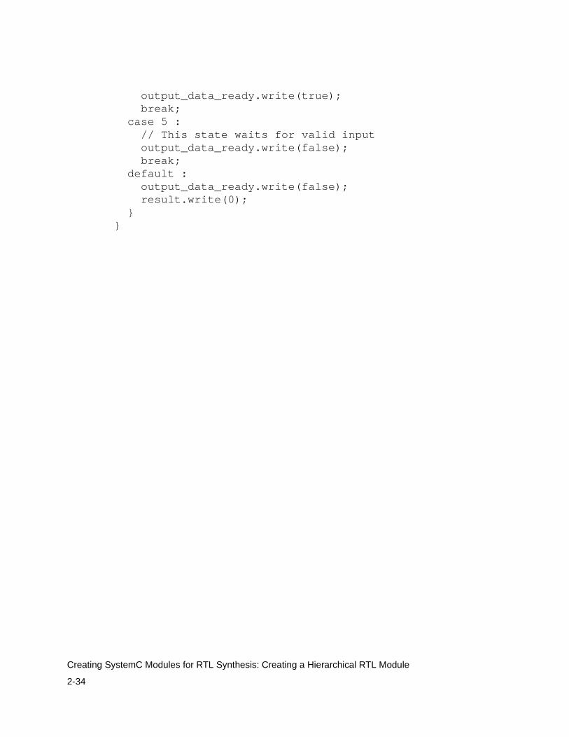
2-34
Creating SystemC Modules for RTL Synthesis: Creating a Hierarchical RTL Module
output_data_ready.write(true); break; case 5 : // This state waits for valid input output_data_ready.write(false); break; default : output_data_ready.write(false); result.write(0); }}
3-1
3Using the Synthesizable Subset 3
This chapter explains the subset of the SystemC and C/C++ language elements and data types that are used for RTL synthesis. It contains the following sections:
• Converting to a Synthesizable Subset
• Modifying Data for Synthesis
• Recommendations About Modification for Synthesis

3-2
Using the Synthesizable Subset: Converting to a Synthesizable Subset
Converting to a Synthesizable Subset
To prepare for synthesis, you need to convert all nonsynthesizable code into synthesizable code. This is required only for functionality that is to be synthesized.
Although you can use any SystemC class or C++ construct for simulation and other stages of the design process, only a subset of the language can be used for synthesis. You can use #ifdef and #endif to comment out code that is needed only for simulation. For example, you can exclude trace and print statements with these compiler directives.
SystemC and C++ Synthesizable Subsets
The synthesizable subsets of SystemC and C++ are provided in the sections that follow. Wherever possible, a recommended corrective action is indicated for converting nonsynthesizable constructs into synthesizable constructs. For many nonsynthesizable constructs, there is no obvious recommendation for converting them into synthesizable constructs or there are numerous ways to convert them. In such cases, a recommended corrective action is not indicated. Familiarize yourself with the synthesizable subset and use it as much as possible in your pure C/C++ or high-level SystemC models to minimize the modification effort for synthesis.
You can use any SystemC or C++ construct for a testbench. You do not need to restrict your code to the synthesizable subset in the testbench.

3-3
Using the Synthesizable Subset: Converting to a Synthesizable Subset
Nonsynthesizable SystemC Constructs
The SystemC constructs listed in Table 3-1 are not supported for RTL synthesis.
Table 3-1 Nonsynthesizable SystemC Constructs for RTL Synthesis
Category Construct Comment Corrective action
Thread process SC_THREAD Used for modeling a testbench but not supported for synthesis.
CTHREAD process
SC_CTHREAD Used for simulation and modeling at the behavioral level.
Main function sc_main() Used for simulation.
Clock generators
sc_start() Used for simulation. Use only in sc_main( ).
Communication sc_interface,sc_port,sc_mutex,sc_fifo
Used for modeling communication
Comment out for synthesis
Global watching watching() Not supported for RTL synthesis
Local watching W_BEGIN, W_END, W_DO, W_ESCAPE
Not supported.
Synchronization Master-slave library of SystemC
Used for synchronization of events
Comment out for synthesis
Tracing sc_trace, sc_create*trace_file
Creates waveforms of signals, channels, and variables for simulation.
Comment out for synthesis.
3-4
Using the Synthesizable Subset: Converting to a Synthesizable Subset
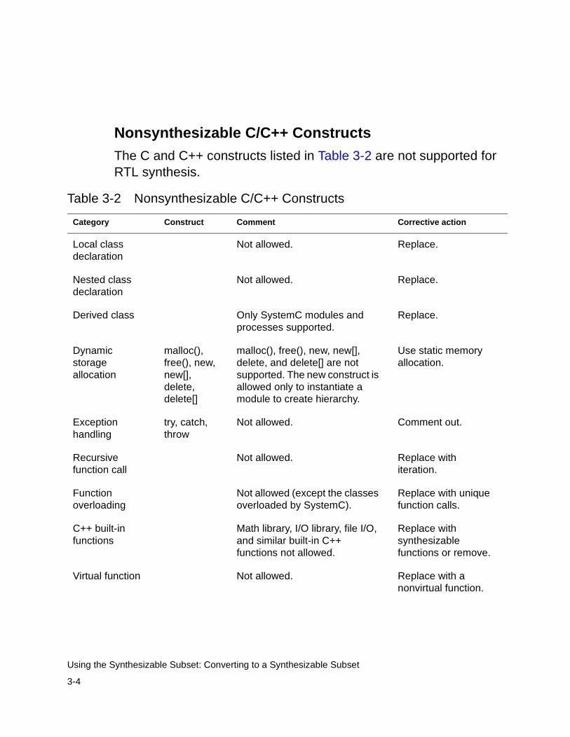
Nonsynthesizable C/C++ Constructs
The C and C++ constructs listed in Table 3-2 are not supported for RTL synthesis.
Table 3-2 Nonsynthesizable C/C++ Constructs
Category Construct Comment Corrective action
Local class declaration
Not allowed. Replace.
Nested class declaration
Not allowed. Replace.
Derived class Only SystemC modules and processes supported.
Replace.
Dynamic storage allocation
malloc(), free(), new, new[], delete, delete[]
malloc(), free(), new, new[], delete, and delete[] are not supported. The new construct is allowed only to instantiate a module to create hierarchy.
Use static memory allocation.
Exception handling
try, catch, throw
Not allowed. Comment out.
Recursive function call
Not allowed. Replace with iteration.
Function overloading
Not allowed (except the classes overloaded by SystemC).
Replace with unique function calls.
C++ built-in functions
Math library, I/O library, file I/O, and similar built-in C++ functions not allowed.
Replace with synthesizable functions or remove.
Virtual function Not allowed. Replace with a nonvirtual function.

3-5
Using the Synthesizable Subset: Converting to a Synthesizable Subset
Inheritance Not allowed. Create an independent SC_MODULE.
Multiple inheritance
Not allowed. Create independent modules.
Member access control specifiers
public, protected, private, friend
Allowed in code but ignored for synthesis. All member access is public.
Accessing struct members with the (->) operator
-> operator Not allowed, except for module instantiation.
Replace with access using the period (.) operator.
Static member Not allowed. Replace with nonstatic member variable.
Dereference operator
* and & operators
Not allowed. Replace dereferencing with array accessing.
for loop comma operator
, operator The comma operator is not allowed in a for loop definition.
Remove the comma operators.
Unbounded loop Not allowed. Replace with a bounded loop, such as a for loop.
Out-of-bound array access
Not allowed. Replace with in-bound array access.
Operator overloading
Not allowed (except the classes overloaded by SystemC).
Replace overloading with unique function calls.
Table 3-2 Nonsynthesizable C/C++ Constructs (Continued)
Category Construct Comment Corrective action
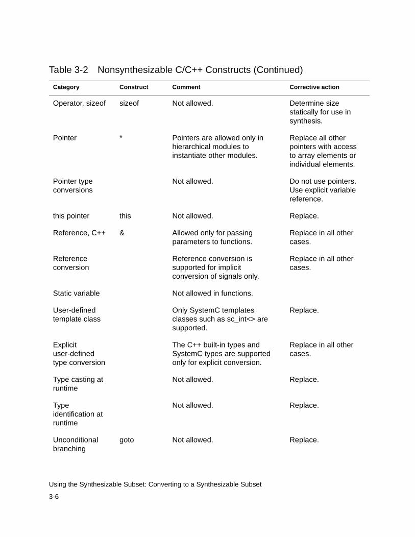
3-6
Using the Synthesizable Subset: Converting to a Synthesizable Subset
Operator, sizeof sizeof Not allowed. Determine size statically for use in synthesis.
Pointer * Pointers are allowed only in hierarchical modules to instantiate other modules.
Replace all other pointers with access to array elements or individual elements.
Pointer type conversions
Not allowed. Do not use pointers. Use explicit variable reference.
this pointer this Not allowed. Replace.
Reference, C++ & Allowed only for passing parameters to functions.
Replace in all other cases.
Reference conversion
Reference conversion is supported for implicit conversion of signals only.
Replace in all other cases.
Static variable Not allowed in functions.
User-defined template class
Only SystemC templates classes such as sc_int<> are supported.
Replace.
Explicit user-defined type conversion
The C++ built-in types and SystemC types are supported only for explicit conversion.
Replace in all other cases.
Type casting at runtime
Not allowed. Replace.
Type identification at runtime
Not allowed. Replace.
Unconditional branching
goto Not allowed. Replace.
Table 3-2 Nonsynthesizable C/C++ Constructs (Continued)
Category Construct Comment Corrective action

3-7
Using the Synthesizable Subset: Modifying Data for Synthesis
Modifying Data for Synthesis
A pure C/C++ model or a high-level SystemC model typically uses native C++ types or aggregates (structures) of such types. Native C++ types such as int, char, bool, and long have fixed, platform-dependent widths, which are often not the correct width for efficient hardware. For example, you might need only a 6-bit integer for a particular operation, instead of the native C++ 32-bit integer. In addition, C++ does not support four-valued logic vectors, operations such as concatenation, and other features that are needed to efficiently describe hardware operations.
SystemC provides a set of limited-precision and arbitrary-precision data types that allows you to create integers, bit vectors, and logic vectors of any length. SystemC also supports all common operations on these data types.
Unions Not allowed. Replace with structs.
Global variable Not supported for synthesis. Replace with local variables.
Member variable
Member variables accessed by two or more SC_METHOD processes are not supported. However, access to member variables by only one process is supported.
Use signals instead of variables for communication between processes.
Volatile variable Not allowed. Use only nonvolatile variables.
Table 3-2 Nonsynthesizable C/C++ Constructs (Continued)
Category Construct Comment Corrective action
3-8
Using the Synthesizable Subset: Modifying Data for Synthesis
To modify a SystemC model for RTL synthesis, you need to evaluate all variable declarations, formal parameters, and return types of all functions to determine the appropriate data type and the appropriate widths of each data type. Selecting the data widths is a design decision, and it is typically a tradeoff between the cost of hardware and the required precision. This decision is, therefore, left to you.
Synthesizable Data Types
C++ is a strongly typed language. Every constant, port, signal, variable, function return type, and parameter is declared as a data type, such as bool or sc_int<n>, and can hold or return a value of that type. Therefore, it is important that you use the correct data types in expressions.
Nonsynthesizable Data Types
All SystemC and C++ data types can be used for RTL synthesis, except the following types:
• Floating-point types such as float and double
• Fixed-point types sc_fixed, sc_ufixed, sc_fix, and sc_ufix
• Access types such as pointers
• File types such as FILE
• I/O streams such as stdout and cout
3-9
Using the Synthesizable Subset: Modifying Data for Synthesis
Recommended Data Types for Synthesis
For best synthesis, use appropriate data types and bit-widths so unnecessary hardware is not built during RTL synthesis.
The following are some general recommendations about data type selections:
• For a single-bit variable, use the native C++ type bool.
• For variables with a width of 64 bits or less, use sc_int or sc_uint data types. Use sc_uint for all logic and unsigned arithmetic operations. Use sc_int for signed arithmetic operations as well as for logic operations. These types produce the fastest simulation runtimes of the SystemC types.
• For variables larger than 64 bits, use sc_bigint or sc_biguint if you want to do arithmetic operations with these variables.
• Use sc_logic or sc_lv only when you need to model three-state signals or buses. When you use these data types, avoid comparison with X and Z values in your synthesizable code, because such comparisons are not synthesizable.
• Use native C++ integer types for loop counters.
• Use the native C++ data types with caution, because their size is platform-dependent. For example, on most platforms, a char is 8 bits wide, a short is 16 bits wide, and both an int and long are 32 bits wide. An int, however, can be 16, 32, or 64 bits wide.

3-10
Using the Synthesizable Subset: Modifying Data for Synthesis
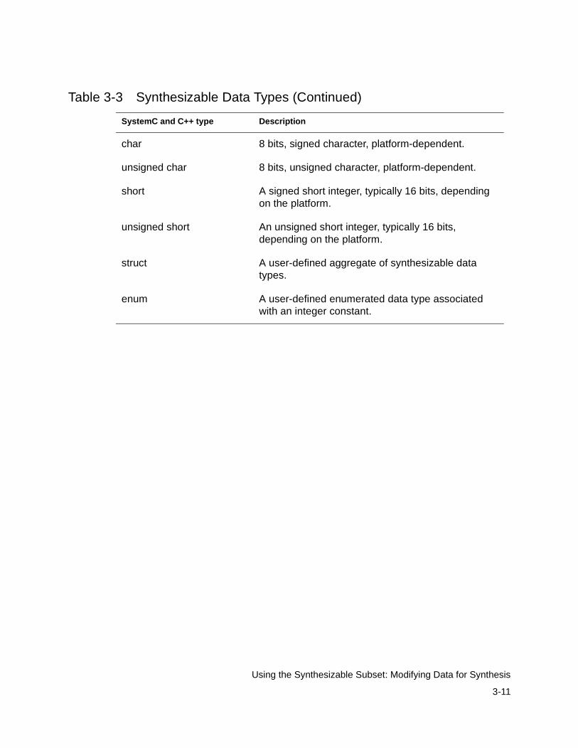
To restrict bit size for synthesis, use the recommended SystemC data types summarized in Table 3-3 in place of the equivalent C++ native type. For example, change an int type to an sc_int<n> type.
Table 3-3 Synthesizable Data Types
SystemC and C++ type Description
sc_bit A single-bit true or false value. Supported but not recommended. Use the bool data type.
sc_bv<n> Arbitrary-length bit vector. Use sc_uint<n> when possible.
sc_logic A single-bit 0, 1, X, or Z.
sc_lv<n> Arbitrary-length logic vector.
sc_int<n> Fixed-precision integers restricted in size up to 64 bits and 64 bits of precision during operations.
sc_uint<n> Fixed-precision integers restricted in size up to 64 bits and 64 bits of precision during operations, unsigned.
sc_bigint<n> Arbitrary-precision integers recommended for sizes over 64 bits and unlimited precision.
sc_biguint<n> Arbitrary-precision integers recommended for sizes over 64 bits and unlimited precision, unsigned.
bool A single-bit true or false value.
int A signed integer, typically 32 or 64 bits, depending on the platform.
unsigned int An unsigned integer, typically 32 or 64 bits, depending on the platform.
long A signed integer, typically 32 bits or longer, depending on the platform.
unsigned long An unsigned integer, typically 32 bits or longer, depending on the platform.
3-11
Using the Synthesizable Subset: Modifying Data for Synthesis
char 8 bits, signed character, platform-dependent.
unsigned char 8 bits, unsigned character, platform-dependent.
short A signed short integer, typically 16 bits, depending on the platform.
unsigned short An unsigned short integer, typically 16 bits, depending on the platform.
struct A user-defined aggregate of synthesizable data types.
enum A user-defined enumerated data type associated with an integer constant.
Table 3-3 Synthesizable Data Types (Continued)
SystemC and C++ type Description
3-12
Using the Synthesizable Subset: Modifying Data for Synthesis
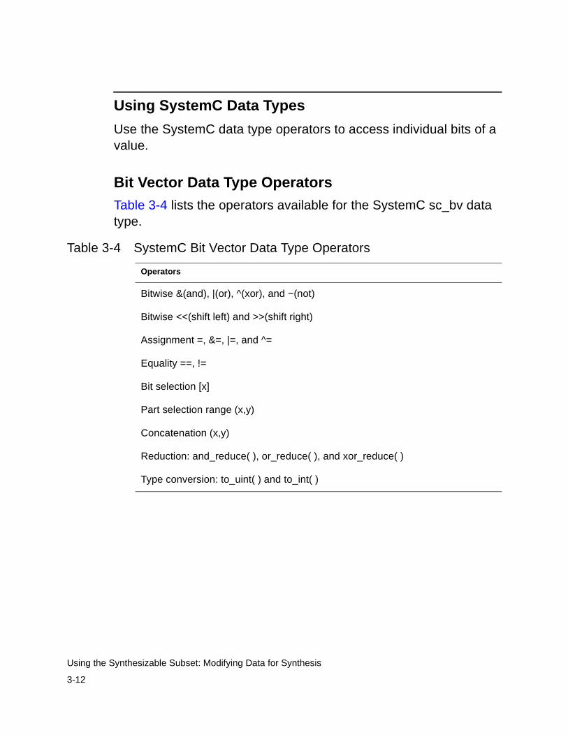
Using SystemC Data Types
Use the SystemC data type operators to access individual bits of a value.
Bit Vector Data Type Operators
Table 3-4 lists the operators available for the SystemC sc_bv data type.
Table 3-4 SystemC Bit Vector Data Type Operators
Operators
Bitwise &(and), |(or), ^(xor), and ~(not)
Bitwise <<(shift left) and >>(shift right)
Assignment =, &=, |=, and ^=
Equality ==, !=
Bit selection [x]
Part selection range (x,y)
Concatenation (x,y)
Reduction: and_reduce( ), or_reduce( ), and xor_reduce( )
Type conversion: to_uint( ) and to_int( )
3-13
Using the Synthesizable Subset: Modifying Data for Synthesis
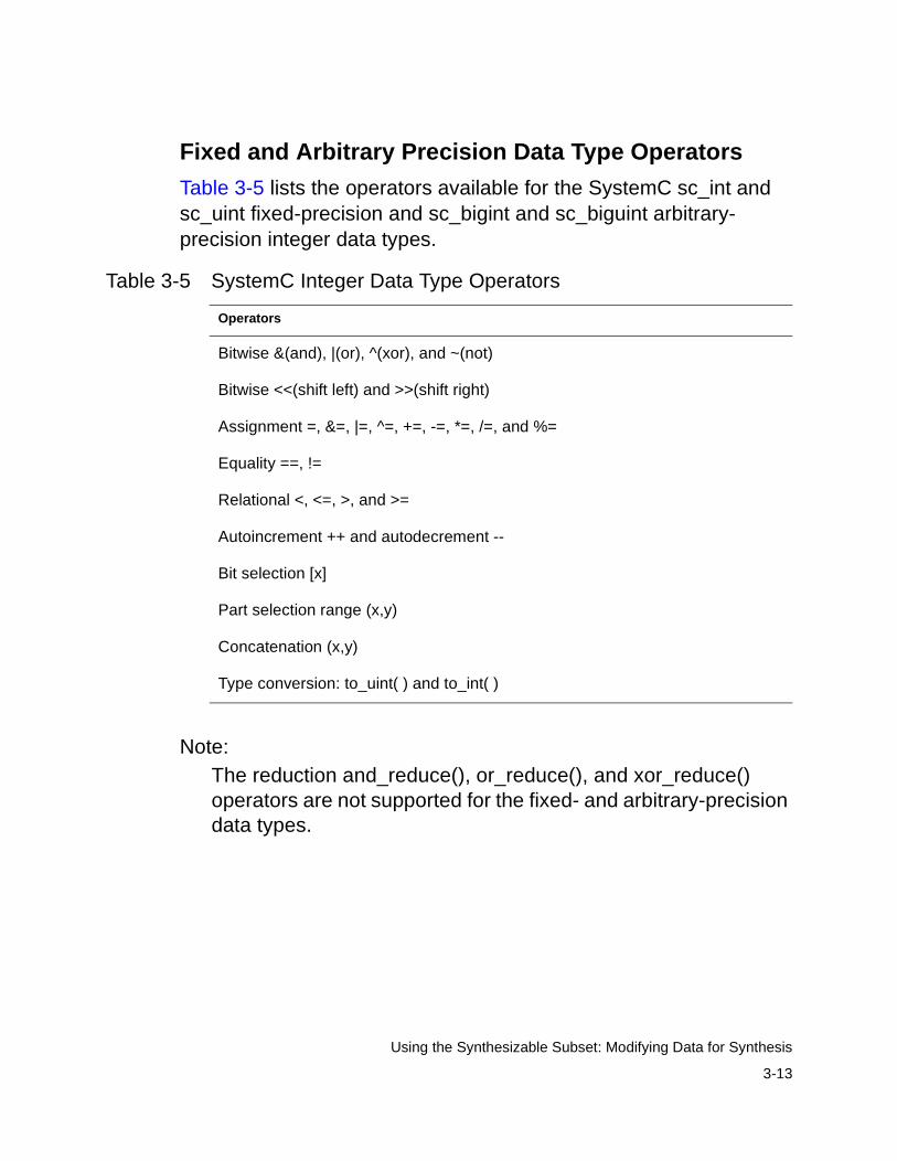
Fixed and Arbitrary Precision Data Type Operators
Table 3-5 lists the operators available for the SystemC sc_int and sc_uint fixed-precision and sc_bigint and sc_biguint arbitrary- precision integer data types.
Note: The reduction and_reduce(), or_reduce(), and xor_reduce() operators are not supported for the fixed- and arbitrary-precision data types.
Table 3-5 SystemC Integer Data Type Operators
Operators
Bitwise &(and), |(or), ^(xor), and ~(not)
Bitwise <<(shift left) and >>(shift right)
Assignment =, &=, |=, ^=, +=, -=, *=, /=, and %=
Equality ==, !=
Relational <, <=, >, and >=
Autoincrement ++ and autodecrement --
Bit selection [x]
Part selection range (x,y)
Concatenation (x,y)
Type conversion: to_uint( ) and to_int( )
3-14
Using the Synthesizable Subset: Modifying Data for Synthesis
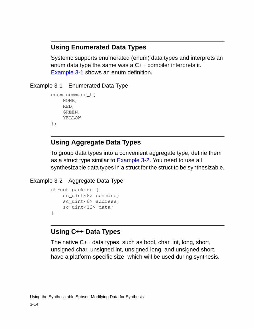
Using Enumerated Data Types
Systemc supports enumerated (enum) data types and interprets an enum data type the same was a C++ compiler interprets it. Example 3-1 shows an enum definition.
Example 3-1 Enumerated Data Type
enum command_t{ NONE, RED, GREEN, YELLOW};
Using Aggregate Data Types
To group data types into a convenient aggregate type, define them as a struct type similar to Example 3-2. You need to use all synthesizable data types in a struct for the struct to be synthesizable.
Example 3-2 Aggregate Data Type
struct package { sc_uint<8> command; sc_uint<8> address; sc_uint<12> data;}
Using C++ Data Types
The native C++ data types, such as bool, char, int, long, short, unsigned char, unsigned int, unsigned long, and unsigned short, have a platform-specific size, which will be used during synthesis.

3-15
Using the Synthesizable Subset: Modifying Data for Synthesis
Data Members of a Module
Do not use data members for interprocess communication, because it can lead to nondeterminism (order dependencies) during simulation and it can cause mismatches between the results of pre- and post-synthesis simulation. Instead of a data member for interprocess communication, use an sc_signal for this purpose.
Example 3-3 shows (in bold) a data member variable named count that is incorrectly used to communicate between the do_count( ) and outregs( ) processes. A value is written to the count variable in the do_count( ) process, and a value is read from the same variable in the outregs( ) process. The order in which the two processes execute cannot be predicted—therefore, you cannot determine whether writing to the count variable is happening before or after count is incremented.
Example 3-3 Incorrect Use of a Data Member Variable for Interprocess Communication
/****mem_var_bad.h****/#include "systemc.h"
SC_MODULE(counter) { sc_in<bool> clk; sc_in<bool> reset_z; sc_out<sc_uint<4> > count_out; sc_uint<4> count; // Member Variable SC_CTOR(counter) { SC_METHOD(do_count); sensitive_pos << clk; sensitive_neg << reset_z;
SC_METHOD(outregs); sensitive_pos << clk; sensitive_neg << reset_z; }
3-16
Using the Synthesizable Subset: Modifying Data for Synthesis
void do_count() { if (reset.read() == 0) count = 0; else count++; }
void outregs() { if (reset.read() == 0) count_out.write(0); else count_out.write(count); }
};
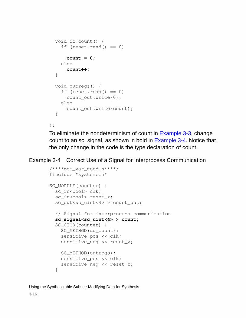
To eliminate the nondeterminism of count in Example 3-3, change count to an sc_signal, as shown in bold in Example 3-4. Notice that the only change in the code is the type declaration of count.
Example 3-4 Correct Use of a Signal for Interprocess Communication
/****mem_var_good.h****/#include "systemc.h"
SC_MODULE(counter) { sc_in<bool> clk; sc_in<bool> reset_z; sc_out<sc_uint<4> > count_out;
// Signal for interprocess communication sc_signal<sc_uint<4> > count; SC_CTOR(counter) { SC_METHOD(do_count); sensitive_pos << clk; sensitive_neg << reset_z;
SC_METHOD(outregs); sensitive_pos << clk; sensitive_neg << reset_z; }

3-17
Using the Synthesizable Subset: Recommendations About Modification for Synthesis
void do_count() { if (reset.read() == 0) count = 0; else count++; }
void outregs() { if (reset.read() == 0) count_out.write(0); else count_out.write(count); }
};
Recommendations About Modification for Synthesis
The following practices are recommended during modification for synthesis:
• After each modification step, reverify your design to ensure that you did not introduce errors during that step.
• Although it is recommended that you thoroughly define at each modification stage, it is not necessary. For example, during data modification, you can change one data type at a time and evaluate the impact on synthesizability and the quality of results. Similarly, you might want to replace one nonsynthesizable construct with a synthesizable construct and reverify the design before replacing the next nonsynthesizable construct.

3-18
Using the Synthesizable Subset: Recommendations About Modification for Synthesis
4-1
4RTL Coding Guidelines 4
This chapter provides SystemC RTL coding guidelines.
It contains the following sections:
• Register Inference
• Three-State Inference
• State Machines
4-2
RTL Coding Guidelines: Register Inference
Register Inference
Register inference allows you to use sequential logic in your designs and keep your designs technology-independent. A register is an array of 1-bit memory devices. A latch is a level-sensitive memory device, and a flip-flop is an edge-triggered memory device. Use the coding guidelines in this section to control flip-flop and latch inference.
As a recommended design practice, whenever you infer registers, ensure that the clock and data inputs to the registers can be directly controlled from the ports of the design. This ensures that you can initialize your design easily during simulation as well as in the actual circuit. You can, of course, infer registers with set and reset, which makes the task of register initialization easier and is highly recommended.
Flip-Flop Inference
RTL synthesis can infer D flip-flops, JK flip-flops, and toggle flip-flops. The following sections provide details about each of these flip-flop types.
Simple D Flip-flop
To infer a simple D flip-flop, make the SC_METHOD process sensitive to only one edge of the clock signal. To infer a positive-edge-triggered flip-flop, make the process sensitive to the positive edge of the clock, and make the process sensitive to the negative edge to infer a negative-edge-triggered flip-flop.
4-3
RTL Coding Guidelines: Register Inference
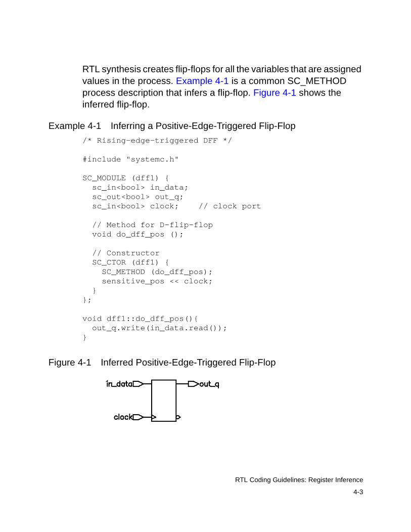
RTL synthesis creates flip-flops for all the variables that are assigned values in the process. Example 4-1 is a common SC_METHOD process description that infers a flip-flop. Figure 4-1 shows the inferred flip-flop.
Example 4-1 Inferring a Positive-Edge-Triggered Flip-Flop
/* Rising-edge-triggered DFF */
#include "systemc.h"
SC_MODULE (dff1) { sc_in<bool> in_data; sc_out<bool> out_q; sc_in<bool> clock; // clock port
// Method for D-flip-flop void do_dff_pos ();
// Constructor SC_CTOR (dff1) { SC_METHOD (do_dff_pos); sensitive_pos << clock; }};
void dff1::do_dff_pos(){ out_q.write(in_data.read());}
Figure 4-1 Inferred Positive-Edge-Triggered Flip-Flop
4-4
RTL Coding Guidelines: Register Inference
D Flip-Flop With an Active-High Asynchronous Setor Reset
To infer a D flip-flop with an asynchronous set or reset, include edge expressions for the clock and the asynchronous signals in the sensitivity list of the SC_METHOD process constructor. Specify the asynchronous signal conditions with an if statement in the SC_METHOD process definition. Example 4-2 shows a typical asynchronous specification. Specify the asynchronous branch conditions before you specify the synchronous branch conditions.
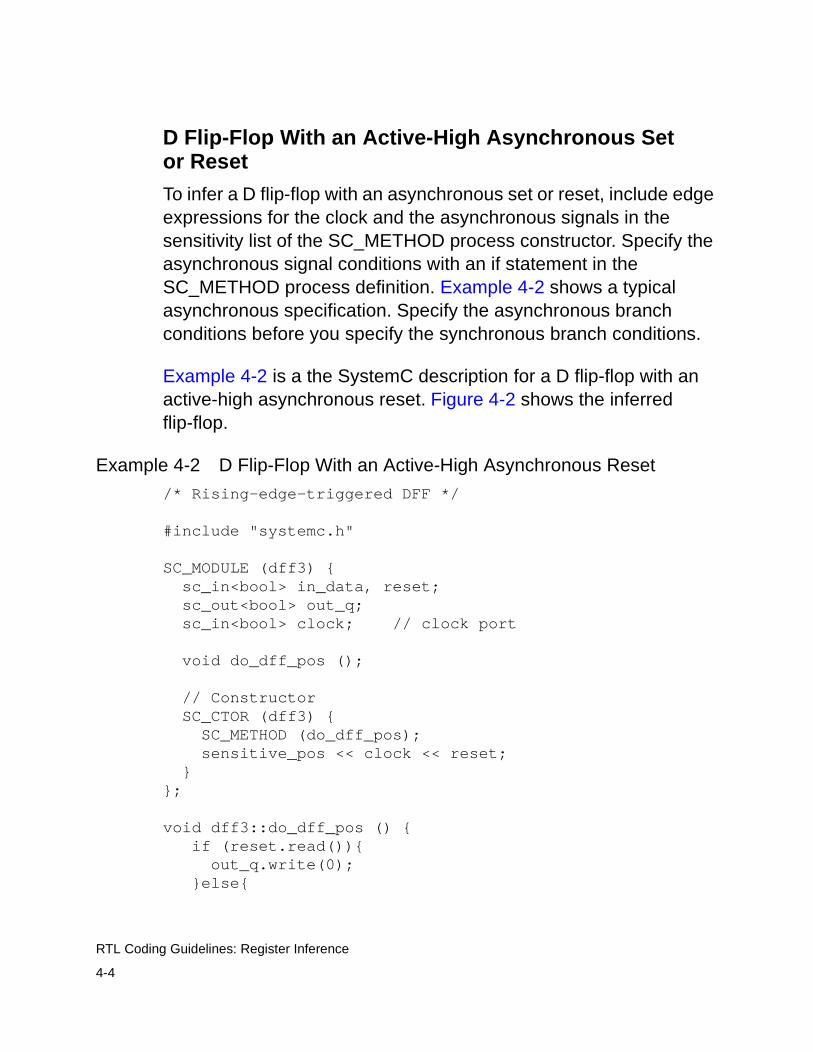
Example 4-2 is a the SystemC description for a D flip-flop with an active-high asynchronous reset. Figure 4-2 shows the inferred flip-flop.
Example 4-2 D Flip-Flop With an Active-High Asynchronous Reset
/* Rising-edge-triggered DFF */
#include "systemc.h"
SC_MODULE (dff3) { sc_in<bool> in_data, reset; sc_out<bool> out_q; sc_in<bool> clock; // clock port
void do_dff_pos ();
// Constructor SC_CTOR (dff3) { SC_METHOD (do_dff_pos); sensitive_pos << clock << reset; }};
void dff3::do_dff_pos () { if (reset.read()){ out_q.write(0); }else{
4-5
RTL Coding Guidelines: Register Inference
out_q.write(in_data.read()); }}
Figure 4-2 D Flip-Flop With an Active-High Asynchronous Reset
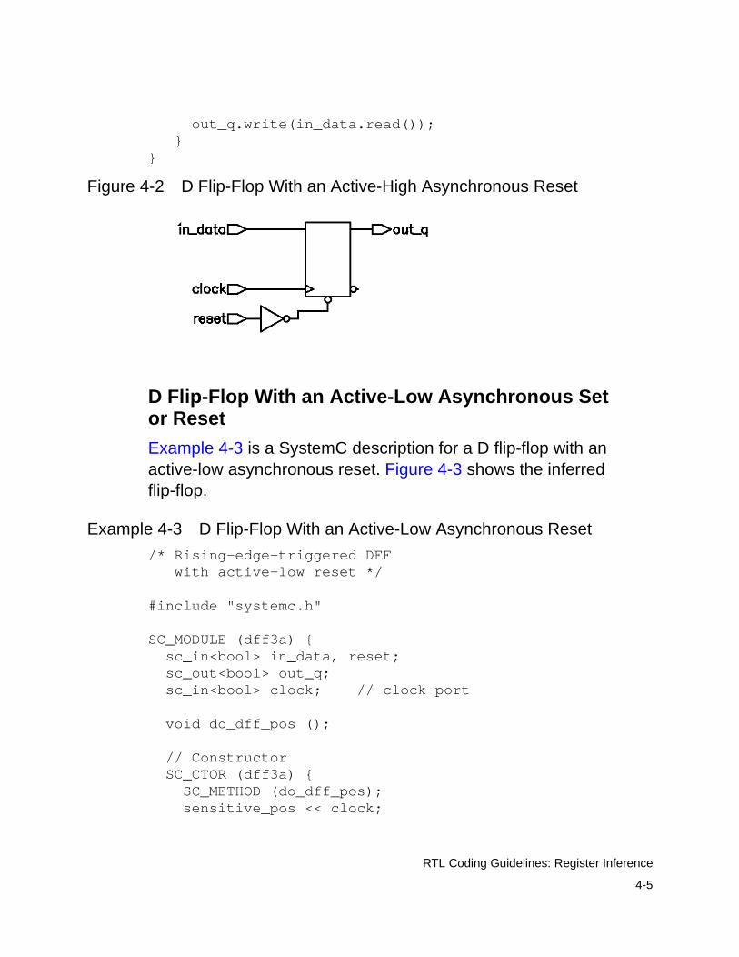
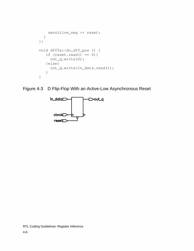
D Flip-Flop With an Active-Low Asynchronous Set or Reset
Example 4-3 is a SystemC description for a D flip-flop with an active-low asynchronous reset. Figure 4-3 shows the inferred flip-flop.
Example 4-3 D Flip-Flop With an Active-Low Asynchronous Reset
/* Rising-edge-triggered DFF with active-low reset */
#include "systemc.h"
SC_MODULE (dff3a) { sc_in<bool> in_data, reset; sc_out<bool> out_q; sc_in<bool> clock; // clock port
void do_dff_pos ();
// Constructor SC_CTOR (dff3a) { SC_METHOD (do_dff_pos); sensitive_pos << clock;
4-6
RTL Coding Guidelines: Register Inference
sensitive_neg << reset; }};
void dff3a::do_dff_pos () { if (reset.read() == 0){ out_q.write(0); }else{ out_q.write(in_data.read()); }}
Figure 4-3 D Flip-Flop With an Active-Low Asynchronous Reset

4-7
RTL Coding Guidelines: Register Inference
D Flip-Flop With Active-High Asynchronous Set and Reset. Example 4-4 is a SystemC description for a D flip-flop with active-high asynchronous set and reset ports. Figure 4-4 shows the inferred flip-flop.
An implied priority exists between set and reset, and reset has priority. This priority is not guaranteed, because it can be implemented differently in various technology libraries. To ensure the correct behavior, assign a high value to either the set or reset at one time, but not to both at the same time.
Example 4-4 Flip-Flop With Asynchronous Set and Reset
/* Rising-edge-triggered DFF */
#include "systemc.h"
SC_MODULE (dff4) { sc_in<bool> in_data, reset, set; sc_out<bool> out_q; sc_in<bool> clock; // clock port
void do_dff_pos ();
// Constructor SC_CTOR (dff4) { SC_METHOD (do_dff_pos); sensitive_pos << clock << reset << set; }};
void dff4::do_dff_pos () { if (reset.read()){ out_q.write(0); }else if (set.read()){ out_q.write(1); }else{ out_q.write(in_data.read()); }}

4-8
RTL Coding Guidelines: Register Inference
Figure 4-4 Flip-Flop With Asynchronous Set and Reset
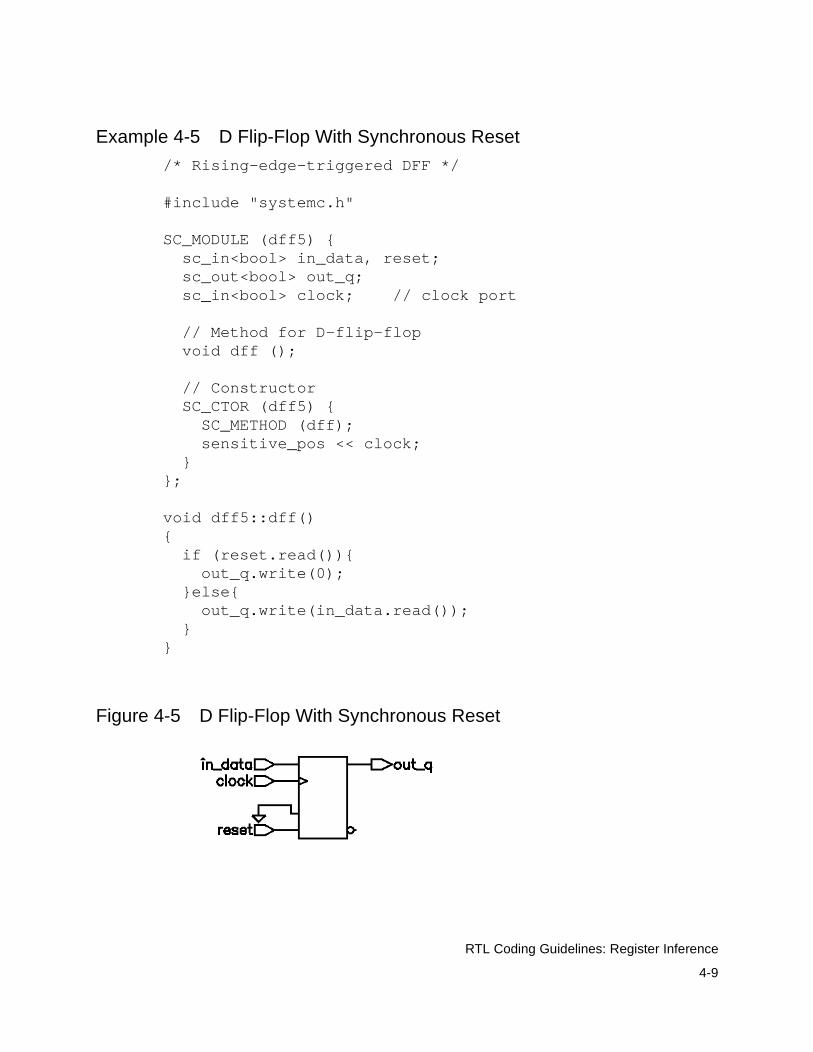
D Flip-Flop With Synchronous Set or Reset
The previous examples illustrated how to infer a D flip-flop with asynchronous controls — one way to initialize or control the state of a sequential device. You can also synchronously reset or set a flip-flop.
If the target technology library does not have a D flip-flop with a synchronous reset, a D flip-flop with synchronous reset logic as the input to the D pin of the flip-flop is inferred. If the reset (or set) logic is not directly in front of the D pin of the flip-flop, initialization problems can occur during gate-level simulation of the design.
To specify a synchronous set or reset input, do not include it in the sensitivity list. Describe the synchronous set or reset test and action in an if statement. Example 4-5 is a SystemC description for a D flip-flop with synchronous reset. Figure 4-5 shows the inferred flip-flop.
4-9
RTL Coding Guidelines: Register Inference
Example 4-5 D Flip-Flop With Synchronous Reset
/* Rising-edge-triggered DFF */
#include "systemc.h"
SC_MODULE (dff5) { sc_in<bool> in_data, reset; sc_out<bool> out_q; sc_in<bool> clock; // clock port
// Method for D-flip-flop void dff ();
// Constructor SC_CTOR (dff5) { SC_METHOD (dff); sensitive_pos << clock; }};
void dff5::dff(){ if (reset.read()){ out_q.write(0); }else{ out_q.write(in_data.read()); }}
Figure 4-5 D Flip-Flop With Synchronous Reset
4-10
RTL Coding Guidelines: Register Inference
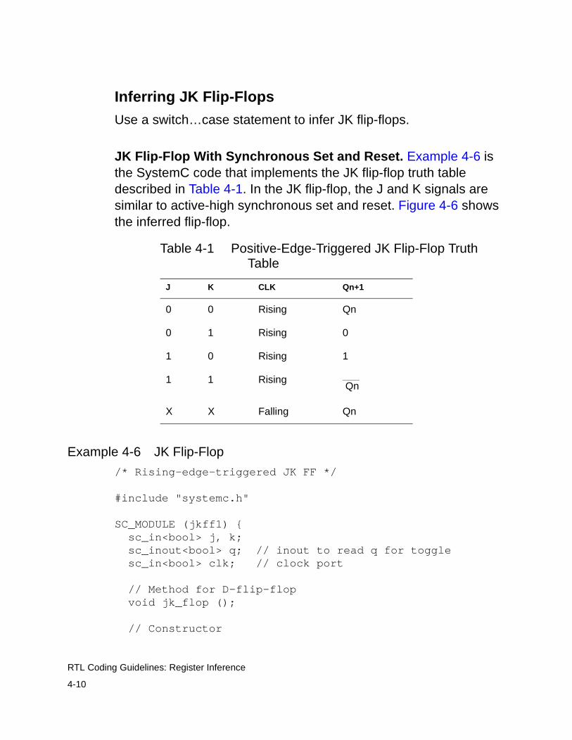
Inferring JK Flip-Flops
Use a switch…case statement to infer JK flip-flops.
JK Flip-Flop With Synchronous Set and Reset. Example 4-6 is the SystemC code that implements the JK flip-flop truth table described in Table 4-1. In the JK flip-flop, the J and K signals are similar to active-high synchronous set and reset. Figure 4-6 shows the inferred flip-flop.
Example 4-6 JK Flip-Flop
/* Rising-edge-triggered JK FF */
#include "systemc.h"
SC_MODULE (jkff1) { sc_in<bool> j, k; sc_inout<bool> q; // inout to read q for toggle sc_in<bool> clk; // clock port
// Method for D-flip-flop void jk_flop ();
// Constructor
Table 4-1 Positive-Edge-Triggered JK Flip-Flop Truth Table
J K CLK Qn+1
0 0 Rising Qn
0 1 Rising 0
1 0 Rising 1
1 1 Rising
X X Falling Qn
Qn

4-11
RTL Coding Guidelines: Register Inference
SC_CTOR (jkff1) { SC_METHOD (jk_flop); sensitive_pos << clk; }};void jkff1::jk_flop() { sc_uint<2> temp; //temp to create vector temp[1] = j.read( ); temp[0] = k.read( ); switch(temp) { case 0x1: q.write(0); // write a zero break; case 0x2: q.write(1); // write a 1 break; case 0x3: // toggle q.write(!q.read()); break; default: break; // no change } }
Figure 4-6 JK Flip-Flop
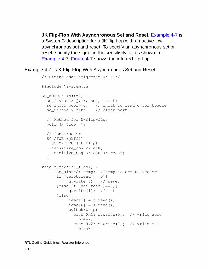
4-12
RTL Coding Guidelines: Register Inference
JK Flip-Flop With Asynchronous Set and Reset. Example 4-7 is a SystemC description for a JK flip-flop with an active-low asynchronous set and reset. To specify an asynchronous set or reset, specify the signal in the sensitivity list as shown in Example 4-7. Figure 4-7 shows the inferred flip-flop.
Example 4-7 JK Flip-Flop With Asynchronous Set and Reset
/* Rising-edge-triggered JKFF */
#include "systemc.h"
SC_MODULE (jkff2) { sc_in<bool> j, k, set, reset; sc_inout<bool> q; // inout to read q for toggle sc_in<bool> clk; // clock port
// Method for D-flip-flop void jk_flop ();
// Constructor SC_CTOR (jkff2) { SC_METHOD (jk_flop); sensitive_pos << clk; sensitive_neg << set << reset; }};void jkff2::jk_flop() { sc_uint<2> temp; //temp to create vector if (reset.read()==0){ q.write(0); // reset }else if (set.read()==0){ q.write(1); // set }else { temp[1] = j.read(); temp[0] = k.read(); switch(temp) { case 0x1: q.write(0); // write zero break; case 0x2: q.write(1); // write a 1 break;
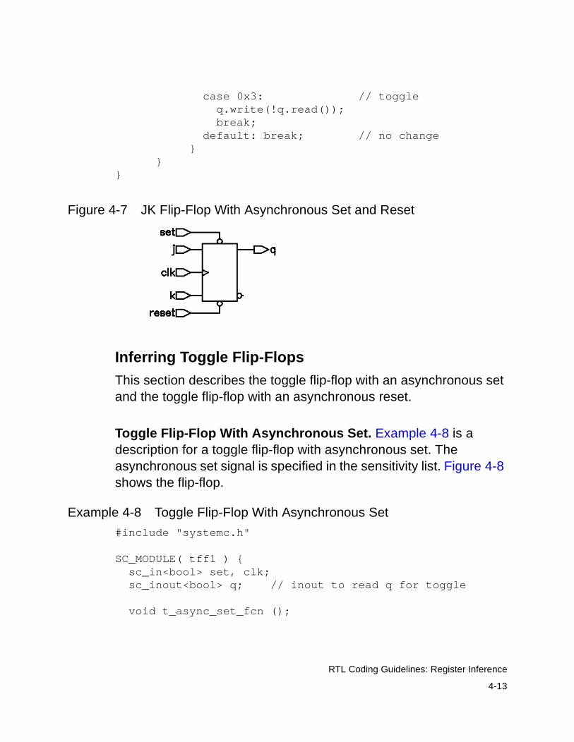
4-13
RTL Coding Guidelines: Register Inference
case 0x3: // toggle q.write(!q.read()); break; default: break; // no change } }}
Figure 4-7 JK Flip-Flop With Asynchronous Set and Reset
Inferring Toggle Flip-Flops
This section describes the toggle flip-flop with an asynchronous set and the toggle flip-flop with an asynchronous reset.
Toggle Flip-Flop With Asynchronous Set. Example 4-8 is a description for a toggle flip-flop with asynchronous set. The asynchronous set signal is specified in the sensitivity list. Figure 4-8 shows the flip-flop.
Example 4-8 Toggle Flip-Flop With Asynchronous Set
#include "systemc.h"
SC_MODULE( tff1 ) { sc_in<bool> set, clk; sc_inout<bool> q; // inout to read q for toggle
void t_async_set_fcn ();

4-14
RTL Coding Guidelines: Register Inference
SC_CTOR( tff1 ) { SC_METHOD( t_async_set_fcn); sensitive_pos << clk << set; }};
void tff1::t_async_set_fcn () { if (set.read()){ q.write(1); }else{ q.write(!q.read()); }}
Figure 4-8 Toggle Flip-Flop With Asynchronous Set
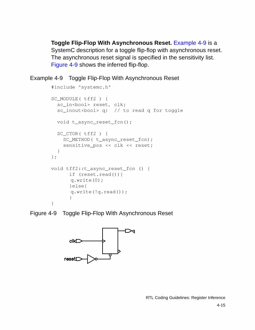
4-15
RTL Coding Guidelines: Register Inference
Toggle Flip-Flop With Asynchronous Reset. Example 4-9 is a SystemC description for a toggle flip-flop with asynchronous reset. The asynchronous reset signal is specified in the sensitivity list. Figure 4-9 shows the inferred flip-flop.
Example 4-9 Toggle Flip-Flop With Asynchronous Reset
#include "systemc.h"
SC_MODULE( tff2 ) { sc_in<bool> reset, clk; sc_inout<bool> q; // to read q for toggle
void t_async_reset_fcn();
SC_CTOR( tff2 ) { SC_METHOD( t_async_reset_fcn); sensitive_pos << clk << reset; }};
void tff2::t_async_reset_fcn () { if (reset.read()){
q.write(0); }else{
q.write(!q.read()); }}
Figure 4-9 Toggle Flip-Flop With Asynchronous Reset
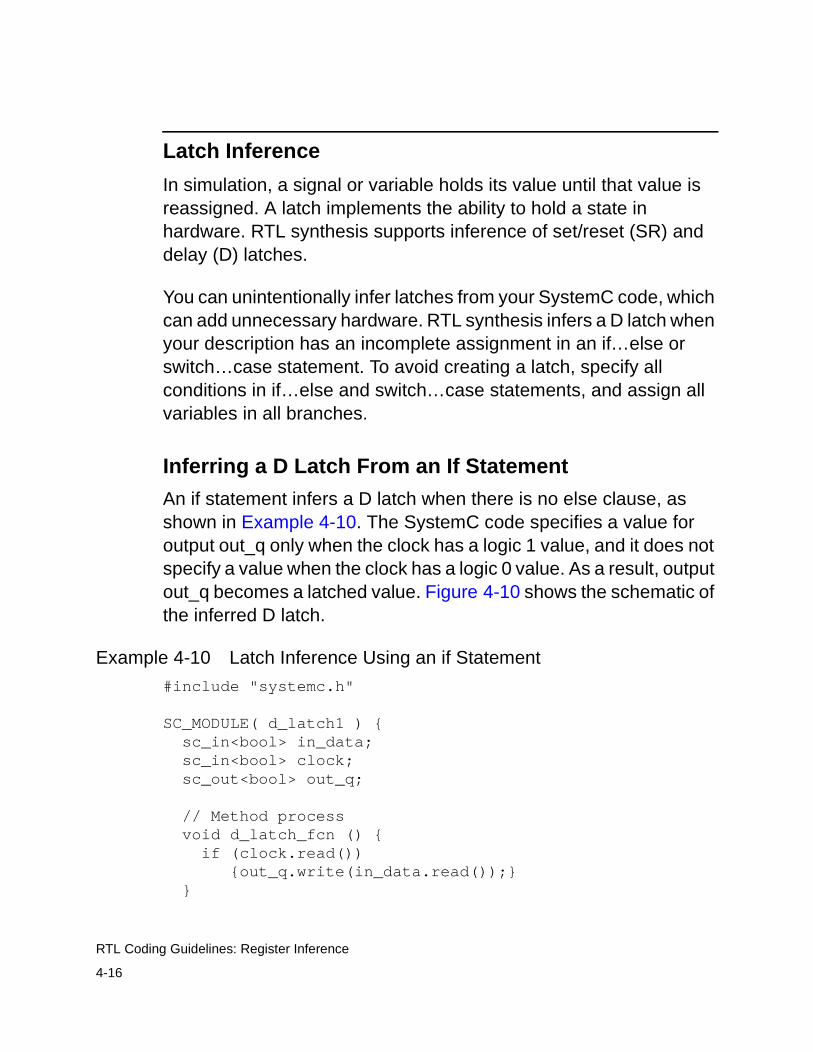
4-16
RTL Coding Guidelines: Register Inference
Latch Inference
In simulation, a signal or variable holds its value until that value is reassigned. A latch implements the ability to hold a state in hardware. RTL synthesis supports inference of set/reset (SR) and delay (D) latches.
You can unintentionally infer latches from your SystemC code, which can add unnecessary hardware. RTL synthesis infers a D latch when your description has an incomplete assignment in an if…else or switch…case statement. To avoid creating a latch, specify all conditions in if…else and switch…case statements, and assign all variables in all branches.
Inferring a D Latch From an If Statement
An if statement infers a D latch when there is no else clause, as shown in Example 4-10. The SystemC code specifies a value for output out_q only when the clock has a logic 1 value, and it does not specify a value when the clock has a logic 0 value. As a result, output out_q becomes a latched value. Figure 4-10 shows the schematic of the inferred D latch.
Example 4-10 Latch Inference Using an if Statement
#include "systemc.h"
SC_MODULE( d_latch1 ) { sc_in<bool> in_data; sc_in<bool> clock; sc_out<bool> out_q;
// Method process void d_latch_fcn () { if (clock.read()) {out_q.write(in_data.read());} }
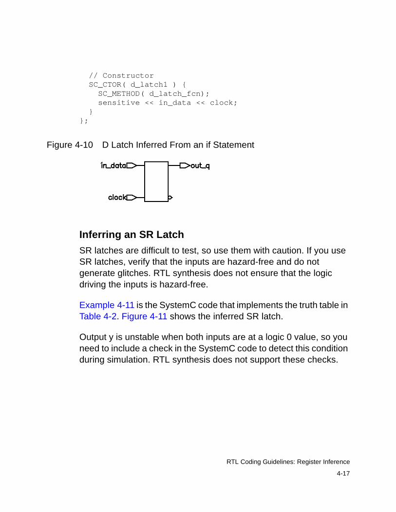
4-17
RTL Coding Guidelines: Register Inference
// Constructor SC_CTOR( d_latch1 ) { SC_METHOD( d_latch_fcn); sensitive << in_data << clock; }};
Figure 4-10 D Latch Inferred From an if Statement
Inferring an SR Latch
SR latches are difficult to test, so use them with caution. If you use SR latches, verify that the inputs are hazard-free and do not generate glitches. RTL synthesis does not ensure that the logic driving the inputs is hazard-free.
Example 4-11 is the SystemC code that implements the truth table in Table 4-2. Figure 4-11 shows the inferred SR latch.
Output y is unstable when both inputs are at a logic 0 value, so you need to include a check in the SystemC code to detect this condition during simulation. RTL synthesis does not support these checks.
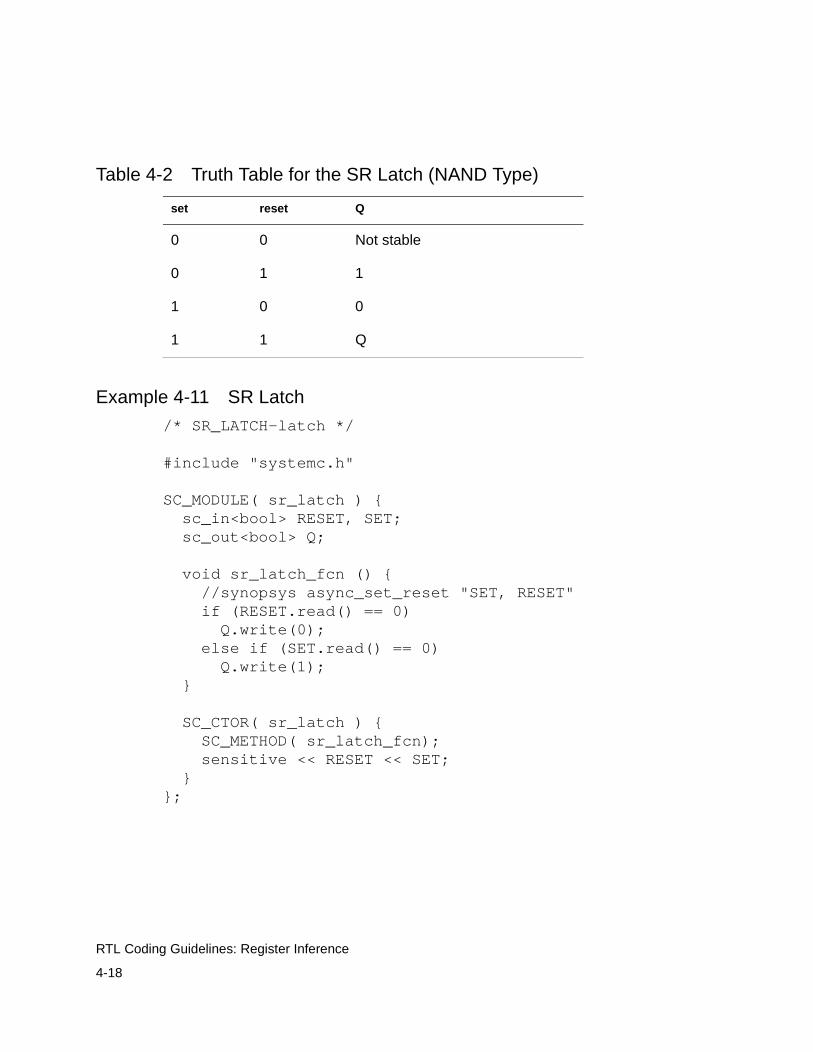
4-18
RTL Coding Guidelines: Register Inference
Example 4-11 SR Latch
/* SR_LATCH-latch */
#include "systemc.h"
SC_MODULE( sr_latch ) { sc_in<bool> RESET, SET; sc_out<bool> Q;
void sr_latch_fcn () { //synopsys async_set_reset "SET, RESET" if (RESET.read() == 0) Q.write(0); else if (SET.read() == 0) Q.write(1); }
SC_CTOR( sr_latch ) { SC_METHOD( sr_latch_fcn); sensitive << RESET << SET; }};
Table 4-2 Truth Table for the SR Latch (NAND Type)
set reset Q
0 0 Not stable
0 1 1
1 0 0
1 1 Q
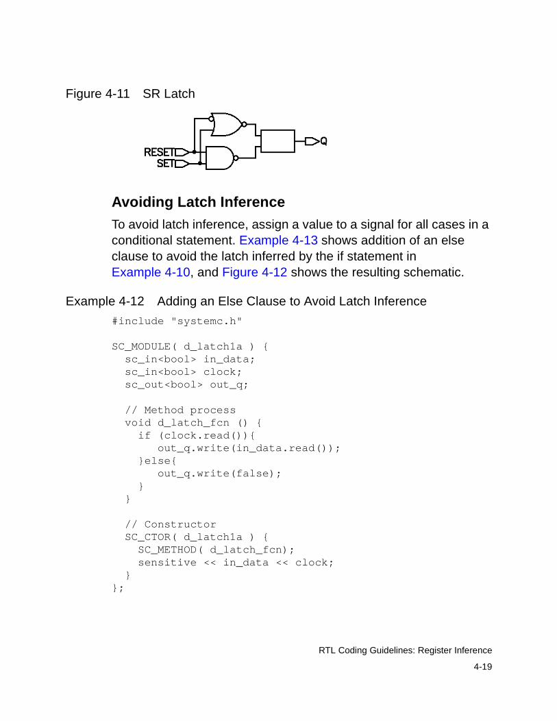
4-19
RTL Coding Guidelines: Register Inference
Figure 4-11 SR Latch
Avoiding Latch Inference
To avoid latch inference, assign a value to a signal for all cases in a conditional statement. Example 4-13 shows addition of an else clause to avoid the latch inferred by the if statement in Example 4-10, and Figure 4-12 shows the resulting schematic.
Example 4-12 Adding an Else Clause to Avoid Latch Inference
#include "systemc.h"
SC_MODULE( d_latch1a ) { sc_in<bool> in_data; sc_in<bool> clock; sc_out<bool> out_q;
// Method process void d_latch_fcn () { if (clock.read()){ out_q.write(in_data.read()); }else{ out_q.write(false); } }
// Constructor SC_CTOR( d_latch1a ) { SC_METHOD( d_latch_fcn); sensitive << in_data << clock; }};
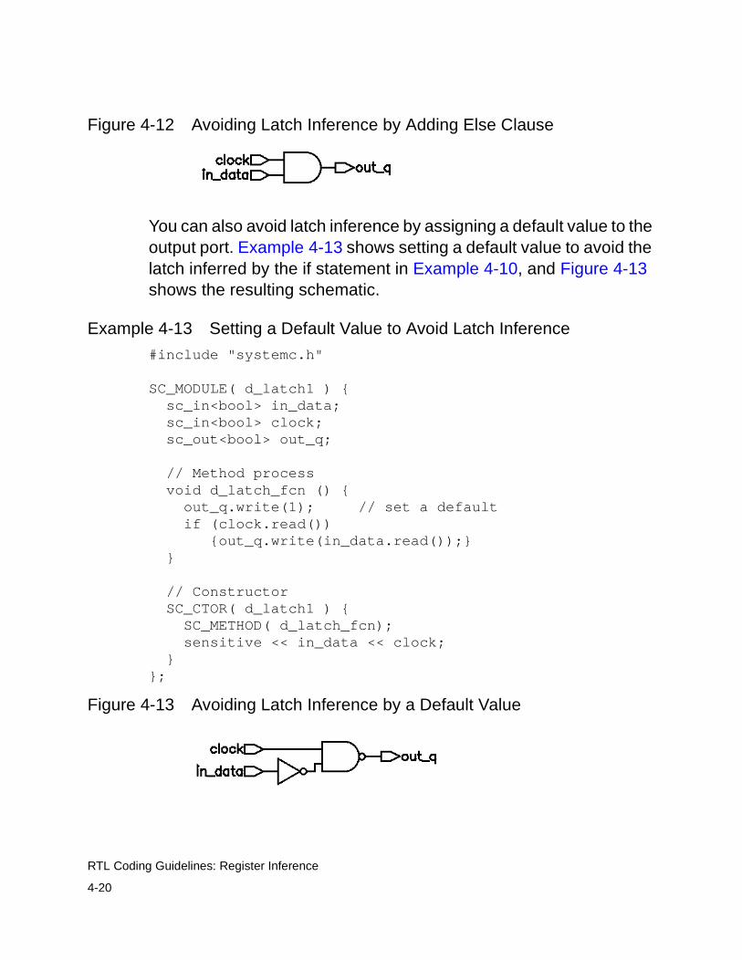
4-20
RTL Coding Guidelines: Register Inference
Figure 4-12 Avoiding Latch Inference by Adding Else Clause
You can also avoid latch inference by assigning a default value to the output port. Example 4-13 shows setting a default value to avoid the latch inferred by the if statement in Example 4-10, and Figure 4-13 shows the resulting schematic.
Example 4-13 Setting a Default Value to Avoid Latch Inference
#include "systemc.h"
SC_MODULE( d_latch1 ) { sc_in<bool> in_data; sc_in<bool> clock; sc_out<bool> out_q;
// Method process void d_latch_fcn () { out_q.write(1); // set a default if (clock.read()) {out_q.write(in_data.read());} }
// Constructor SC_CTOR( d_latch1 ) { SC_METHOD( d_latch_fcn); sensitive << in_data << clock; }};
Figure 4-13 Avoiding Latch Inference by a Default Value
4-21
RTL Coding Guidelines: Register Inference
Inferring a Latch From a Switch Statement
Example 4-14 shows a switch statement that infers D latches because the switch statement does not provide assignments to the out port for all possible values of the in_i input. Figure 4-14 shows the inferred latches.
Example 4-14 Latch Inference From a switch Statement
#include "systemc.h"
SC_MODULE( d_latch2 ) { sc_in<unsigned char> in_i; sc_out<unsigned char> out;
// Method process void d_latch_fcn () { switch (in_i.read()) { case 0: out.write(0x01); break; case 1: out.write(0x02); break; case 2: out.write(0x04); break; case 3: out.write(0x10); break; case 4: out.write(0x20); break; case 5: out.write(0x40); break; } }
// Constructor SC_CTOR( d_latch2 ) { SC_METHOD( d_latch_fcn); sensitive (in_i); }};
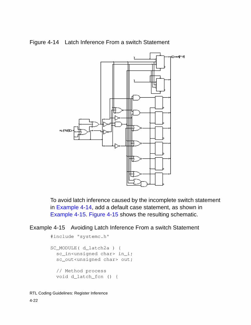
4-22
RTL Coding Guidelines: Register Inference
Figure 4-14 Latch Inference From a switch Statement
To avoid latch inference caused by the incomplete switch statement in Example 4-14, add a default case statement, as shown in Example 4-15. Figure 4-15 shows the resulting schematic.
Example 4-15 Avoiding Latch Inference From a switch Statement
#include "systemc.h"
SC_MODULE( d_latch2a ) { sc_in<unsigned char> in_i; sc_out<unsigned char> out;
// Method process void d_latch_fcn () {
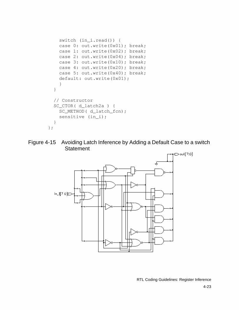
4-23
RTL Coding Guidelines: Register Inference
switch (in_i.read()) { case 0: out.write(0x01); break; case 1: out.write(0x02); break; case 2: out.write(0x04); break; case 3: out.write(0x10); break; case 4: out.write(0x20); break; case 5: out.write(0x40); break; default: out.write(0x01); } }
// Constructor SC_CTOR( d_latch2a ) { SC_METHOD( d_latch_fcn); sensitive (in_i); }};
Figure 4-15 Avoiding Latch Inference by Adding a Default Case to a switch Statement
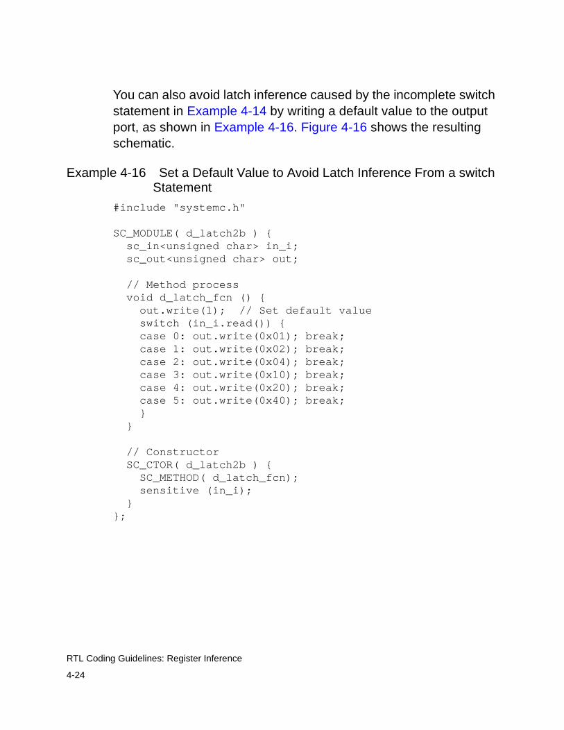
4-24
RTL Coding Guidelines: Register Inference
You can also avoid latch inference caused by the incomplete switch statement in Example 4-14 by writing a default value to the output port, as shown in Example 4-16. Figure 4-16 shows the resulting schematic.
Example 4-16 Set a Default Value to Avoid Latch Inference From a switch Statement
#include "systemc.h"
SC_MODULE( d_latch2b ) { sc_in<unsigned char> in_i; sc_out<unsigned char> out;
// Method process void d_latch_fcn () { out.write(1); // Set default value switch (in_i.read()) { case 0: out.write(0x01); break; case 1: out.write(0x02); break; case 2: out.write(0x04); break; case 3: out.write(0x10); break; case 4: out.write(0x20); break; case 5: out.write(0x40); break; } }
// Constructor SC_CTOR( d_latch2b ) { SC_METHOD( d_latch_fcn); sensitive (in_i); }};
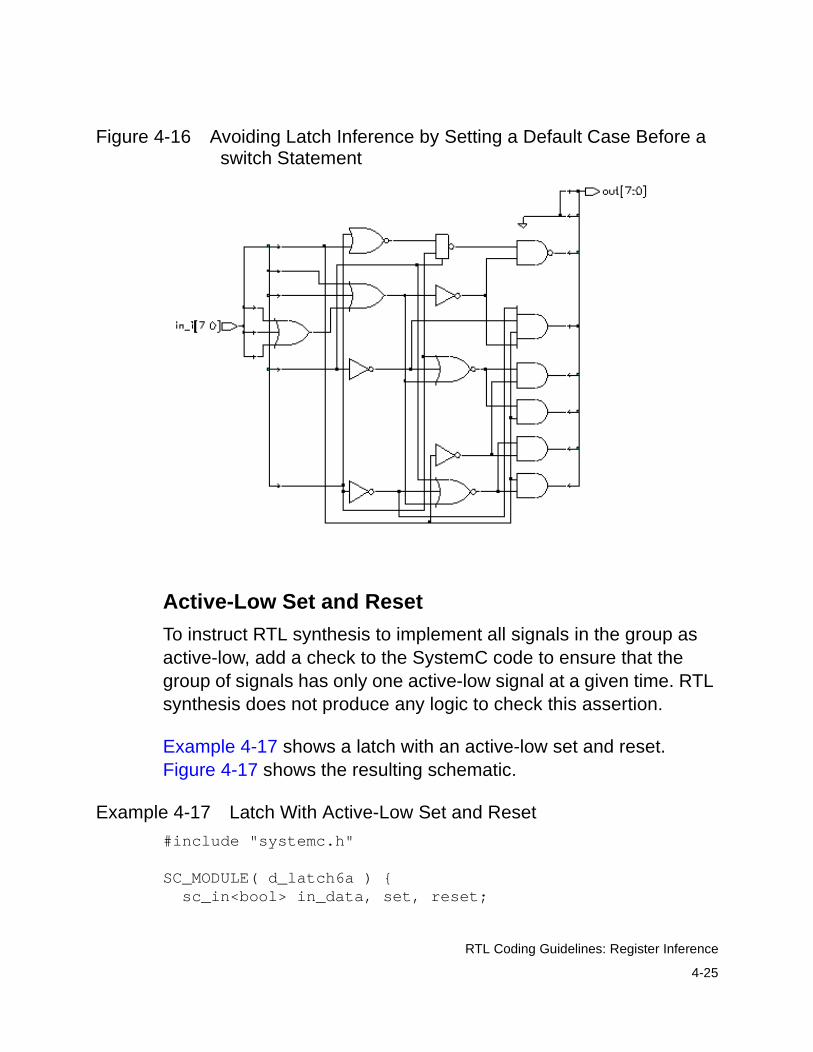
4-25
RTL Coding Guidelines: Register Inference
Figure 4-16 Avoiding Latch Inference by Setting a Default Case Before a switch Statement
Active-Low Set and Reset
To instruct RTL synthesis to implement all signals in the group as active-low, add a check to the SystemC code to ensure that the group of signals has only one active-low signal at a given time. RTL synthesis does not produce any logic to check this assertion.
Example 4-17 shows a latch with an active-low set and reset. Figure 4-17 shows the resulting schematic.
Example 4-17 Latch With Active-Low Set and Reset
#include "systemc.h"
SC_MODULE( d_latch6a ) { sc_in<bool> in_data, set, reset;
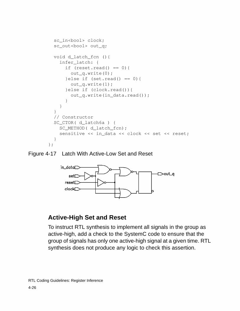
4-26
RTL Coding Guidelines: Register Inference
sc_in<bool> clock; sc_out<bool> out_q;
void d_latch_fcn (){ infer_latch: { if (reset.read() == 0){ out_q.write(0); }else if (set.read() == 0){ out_q.write(1); }else if (clock.read()){ out_q.write(in_data.read()); } } } // Constructor SC_CTOR( d_latch6a ) { SC_METHOD( d_latch_fcn); sensitive << in_data << clock << set << reset; }};
Figure 4-17 Latch With Active-Low Set and Reset
Active-High Set and Reset
To instruct RTL synthesis to implement all signals in the group as active-high, add a check to the SystemC code to ensure that the group of signals has only one active-high signal at a given time. RTL synthesis does not produce any logic to check this assertion.
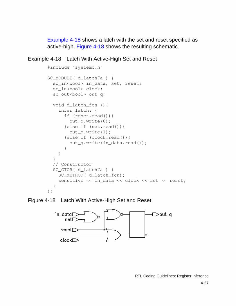
4-27
RTL Coding Guidelines: Register Inference
Example 4-18 shows a latch with the set and reset specified as active-high. Figure 4-18 shows the resulting schematic.
Example 4-18 Latch With Active-High Set and Reset
#include "systemc.h"
SC_MODULE( d_latch7a ) { sc_in<bool> in_data, set, reset; sc_in<bool> clock; sc_out<bool> out_q;
void d_latch_fcn (){ infer_latch: { if (reset.read()){ out_q.write(0); }else if (set.read()){ out_q.write(1); }else if (clock.read()){ out_q.write(in_data.read()); } } } // Constructor SC_CTOR( d_latch7a ) { SC_METHOD( d_latch_fcn); sensitive << in_data << clock << set << reset; }};
Figure 4-18 Latch With Active-High Set and Reset

4-28
RTL Coding Guidelines: Register Inference
D Latch With an Asynchronous Set and Reset
Example 4-19 is a SystemC description for a D latch with an active-low asynchronous set and reset. Figure 4-19 shows the inferred latch.
Example 4-19 Latch With Asynchronous Set and Reset
#include "systemc.h"
SC_MODULE( d_latch6 ) { sc_in<bool> in_data, set, reset; sc_in<bool> clock; sc_out<bool> out_q;
void d_latch_fcn (){ if (reset.read() == 0){ out_q.write(0); }else if (set.read() == 0){ out_q.write(1); }else if (clock.read()){ out_q.write(in_data.read()); } } // Constructor SC_CTOR( d_latch6 ) { SC_METHOD( d_latch_fcn); sensitive << in_data << clock << set << reset; }};
Figure 4-19 Latch With Asynchronous Set and Reset

4-29
RTL Coding Guidelines: Register Inference
D Latch With an Asynchronous Set
Example 4-20 is a SystemC description for a D latch with an asynchronous set. Figure 4-20 shows the inferred latch.
Example 4-20 Latch With Asynchronous Set
#include "systemc.h"
SC_MODULE( d_latch4 ) { sc_in<bool> in_data, set; sc_in<bool> clock; sc_out<bool> out_q;
void d_latch_fcn () { if (set.read() == 0){ out_q.write( 1 ); }else if (clock.read()){ out_q.write(in_data.read()); } }
// Constructor SC_CTOR( d_latch4 ) { SC_METHOD( d_latch_fcn); sensitive << in_data << clock << set; }};
Figure 4-20 Latch With Asynchronous Set
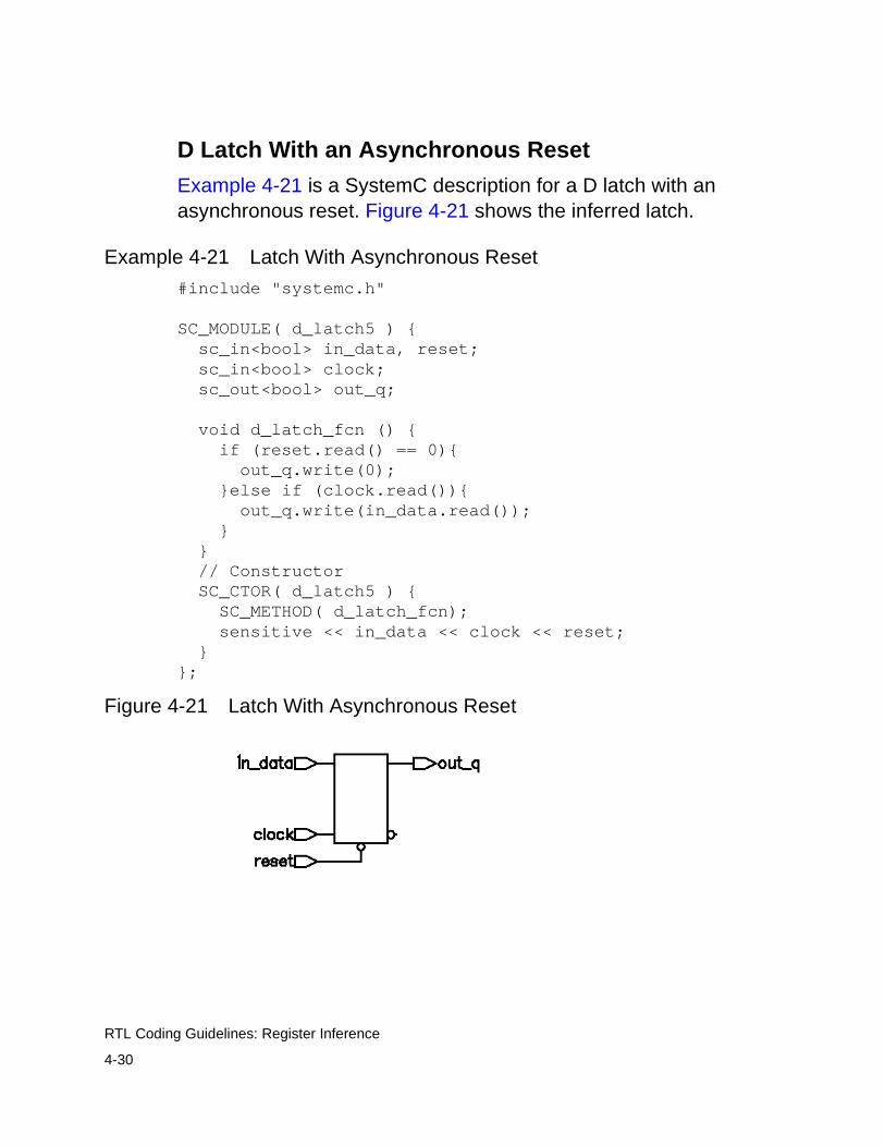
4-30
RTL Coding Guidelines: Register Inference
D Latch With an Asynchronous Reset
Example 4-21 is a SystemC description for a D latch with an asynchronous reset. Figure 4-21 shows the inferred latch.
Example 4-21 Latch With Asynchronous Reset
#include "systemc.h"
SC_MODULE( d_latch5 ) { sc_in<bool> in_data, reset; sc_in<bool> clock; sc_out<bool> out_q;
void d_latch_fcn () { if (reset.read() == 0){ out_q.write(0); }else if (clock.read()){ out_q.write(in_data.read()); } } // Constructor SC_CTOR( d_latch5 ) { SC_METHOD( d_latch_fcn); sensitive << in_data << clock << reset; }};
Figure 4-21 Latch With Asynchronous Reset
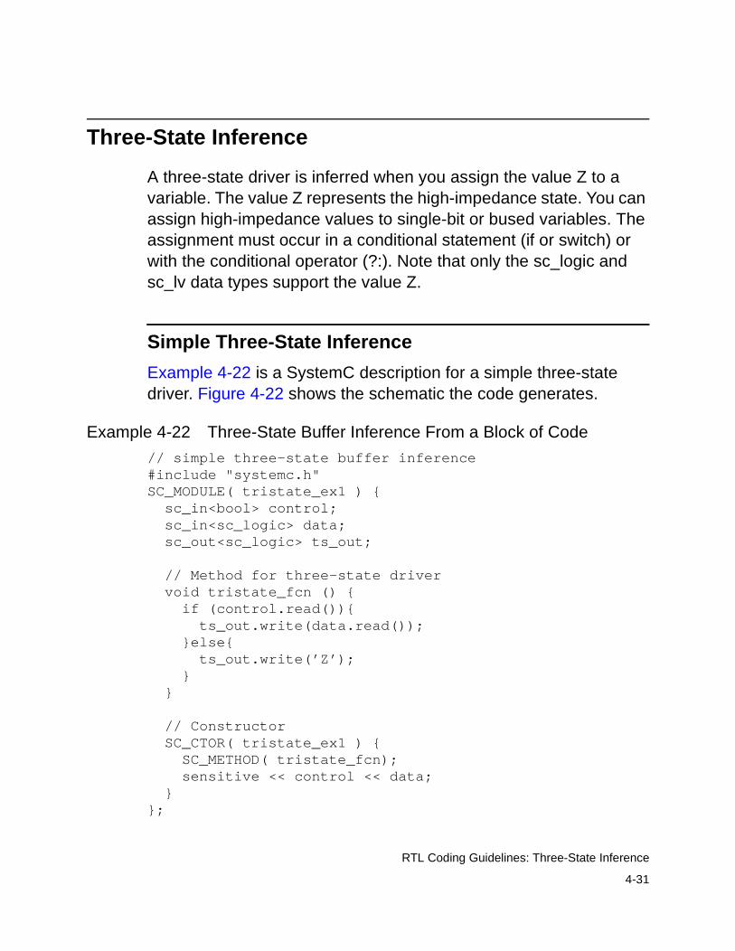
4-31
RTL Coding Guidelines: Three-State Inference
Three-State Inference
A three-state driver is inferred when you assign the value Z to a variable. The value Z represents the high-impedance state. You can assign high-impedance values to single-bit or bused variables. The assignment must occur in a conditional statement (if or switch) or with the conditional operator (?:). Note that only the sc_logic and sc_lv data types support the value Z.
Simple Three-State Inference
Example 4-22 is a SystemC description for a simple three-state driver. Figure 4-22 shows the schematic the code generates.
Example 4-22 Three-State Buffer Inference From a Block of Code
// simple three-state buffer inference#include "systemc.h"SC_MODULE( tristate_ex1 ) { sc_in<bool> control; sc_in<sc_logic> data; sc_out<sc_logic> ts_out;
// Method for three-state driver void tristate_fcn () { if (control.read()){ ts_out.write(data.read()); }else{ ts_out.write(’Z’); } }
// Constructor SC_CTOR( tristate_ex1 ) { SC_METHOD( tristate_fcn); sensitive << control << data; }};

4-32
RTL Coding Guidelines: Three-State Inference
Figure 4-22 Schematic of a Simple Three-State Driver
Example 4-23 is a different instance of three-state inference. In this case, the output is computed and RTL synthesis infers a single three-state driver. Figure 4-23 shows the schematic the code generates.
Example 4-23 Inferring One Three-State Driver
// simple three-state buffer inference#include "systemc.h"
SC_MODULE( tristate_ex2 ) { sc_in<bool> in_sela, in_selb; sc_in<sc_logic> in_a, in_b; sc_out<sc_logic> out_1;
// Method for single three-state driver void tristate_fcn () { out_1.write(’Z’); //default value if (in_sela.read()){ out_1.write(in_a.read()); }else if (in_selb.read()){ out_1.write(in_b.read()); } }
// Constructor SC_CTOR( tristate_ex2 ) { SC_METHOD( tristate_fcn); sensitive << in_sela <<in_selb << in_a << in_b; }};
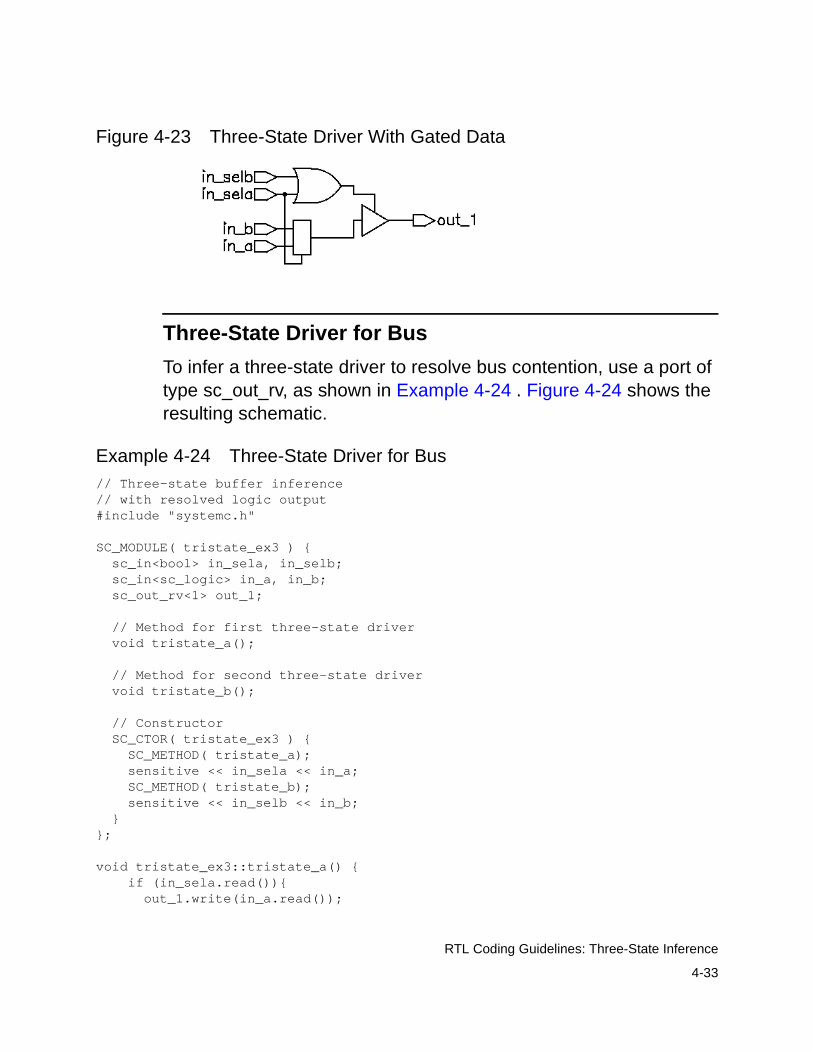
4-33
RTL Coding Guidelines: Three-State Inference
Figure 4-23 Three-State Driver With Gated Data
Three-State Driver for Bus
To infer a three-state driver to resolve bus contention, use a port of type sc_out_rv, as shown in Example 4-24 . Figure 4-24 shows the resulting schematic.
Example 4-24 Three-State Driver for Bus// Three-state buffer inference// with resolved logic output#include "systemc.h"
SC_MODULE( tristate_ex3 ) { sc_in<bool> in_sela, in_selb; sc_in<sc_logic> in_a, in_b; sc_out_rv<1> out_1;
// Method for first three-state driver void tristate_a();
// Method for second three-state driver void tristate_b();
// Constructor SC_CTOR( tristate_ex3 ) { SC_METHOD( tristate_a); sensitive << in_sela << in_a; SC_METHOD( tristate_b); sensitive << in_selb << in_b; }};
void tristate_ex3::tristate_a() { if (in_sela.read()){ out_1.write(in_a.read());

4-34
RTL Coding Guidelines: Three-State Inference
}else{ out_1.write("Z"); }}
void tristate_ex3::tristate_b() { if (in_selb.read()){ out_1.write(in_b.read()); }else{ out_1.write("Z"); }}
Figure 4-24 Three-State Bus Driver Schematic
Registered Three-State Drivers
When a variable is registered in the same process in which it is in a three-state condition, RTL synthesis also registers the enable pin of the three-state gate. Example 4-25 is an example of this type of code. Figure 4-25 shows the schematic generated by the code.
Example 4-25 Three-State Driver With Registered Enable
// simple three-state buffer inference#include "systemc.h"
SC_MODULE( tristate_ex4 ) { sc_in<bool> control; sc_in<sc_logic> data; sc_out<sc_logic> ts_out; sc_in_clk clk;
// Method for three-state driver
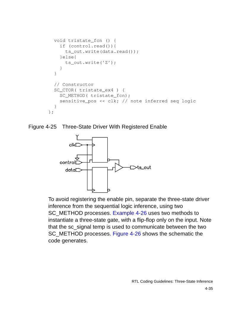
4-35
RTL Coding Guidelines: Three-State Inference
void tristate_fcn () { if (control.read()){ ts_out.write(data.read()); }else{ ts_out.write(’Z’); } }
// Constructor SC_CTOR( tristate_ex4 ) { SC_METHOD( tristate_fcn); sensitive_pos << clk; // note inferred seq logic }};
Figure 4-25 Three-State Driver With Registered Enable
To avoid registering the enable pin, separate the three-state driver inference from the sequential logic inference, using two SC_METHOD processes. Example 4-26 uses two methods to instantiate a three-state gate, with a flip-flop only on the input. Note that the sc_signal temp is used to communicate between the two SC_METHOD processes. Figure 4-26 shows the schematic the code generates.
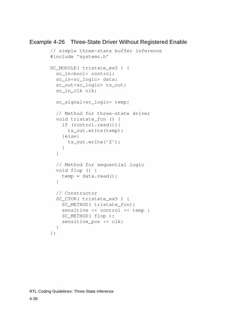
4-36
RTL Coding Guidelines: Three-State Inference
Example 4-26 Three-State Driver Without Registered Enable
// simple three-state buffer inference#include "systemc.h"
SC_MODULE( tristate_ex5 ) { sc_in<bool> control; sc_in<sc_logic> data; sc_out<sc_logic> ts_out; sc_in_clk clk;
sc_signal<sc_logic> temp;
// Method for three-state driver void tristate_fcn () { if (control.read()){ ts_out.write(temp); }else{ ts_out.write(’Z’); } }
// Method for sequential logic void flop () { temp = data.read(); }
// Constructor SC_CTOR( tristate_ex5 ) { SC_METHOD( tristate_fcn); sensitive << control << temp ; SC_METHOD( flop ); sensitive_pos << clk; }};
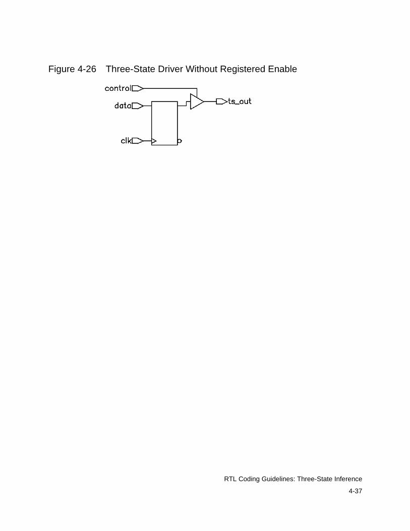
4-37
RTL Coding Guidelines: Three-State Inference
Figure 4-26 Three-State Driver Without Registered Enable

4-38
RTL Coding Guidelines: State Machines
State Machines
Explicitly describe state machines for RTL synthesis. Figure 4-27 shows a Mealy state machine structure.
Figure 4-27 Mealy State Machine
The diagram in Figure 4-27 has one sequential element—the state vector—and two combinational elements, the output logic and the next state logic. Although the output logic and the next state logic are separate in this diagram, you can merge them into one logic block where gates can be shared for a smaller design area.
The output logic is always a function of the current state (state vector) and optionally a function of the inputs. If inputs are included in the output logic, it is a Mealy state machine. If inputs are not included, it is a Moore state machine.
The next state logic is always a function of the current state (state vector) and optionally a function of the inputs.
The common implementations of state machines are
• An SC_METHOD process for updating the state vector and a single common SC_METHOD process for computing both the output and next-state logic
Inputs Outputs
Outputlogic
State
vectorclk
Next statelogic
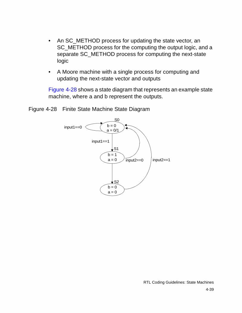
4-39
RTL Coding Guidelines: State Machines
• An SC_METHOD process for updating the state vector, an SC_METHOD process for the computing the output logic, and a separate SC_METHOD process for computing the next-state logic
• A Moore machine with a single process for computing and updating the next-state vector and outputs
Figure 4-28 shows a state diagram that represents an example state machine, where a and b represent the outputs.
Figure 4-28 Finite State Machine State Diagram
S1
S2
input1==0
input1==1
input2==0 input2==1
S0
b = 0a = 0/1
b = 1a = 0
b = 0a = 0
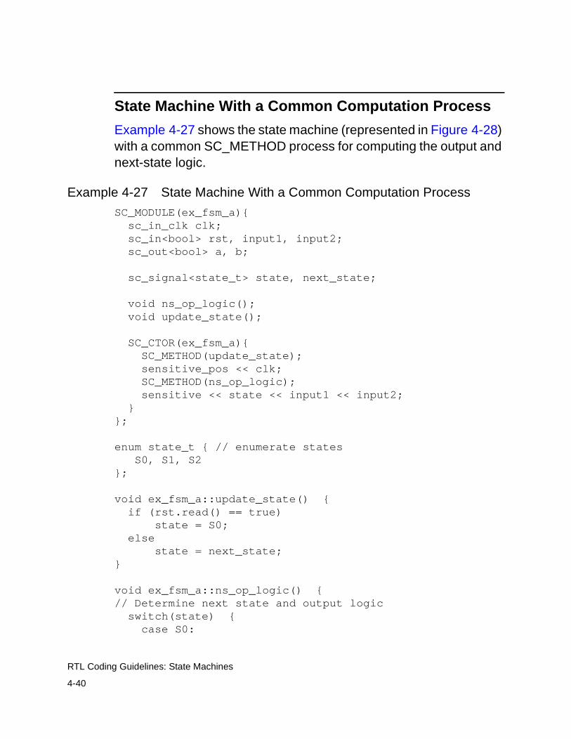
4-40
RTL Coding Guidelines: State Machines
State Machine With a Common Computation Process
Example 4-27 shows the state machine (represented in Figure 4-28) with a common SC_METHOD process for computing the output and next-state logic.
Example 4-27 State Machine With a Common Computation Process
SC_MODULE(ex_fsm_a){ sc_in_clk clk; sc_in<bool> rst, input1, input2; sc_out<bool> a, b;
sc_signal<state_t> state, next_state;
void ns_op_logic(); void update_state();
SC_CTOR(ex_fsm_a){ SC_METHOD(update_state); sensitive_pos << clk; SC_METHOD(ns_op_logic); sensitive << state << input1 << input2; }};
enum state_t { // enumerate states S0, S1, S2};
void ex_fsm_a::update_state() { if (rst.read() == true) state = S0; else state = next_state;}
void ex_fsm_a::ns_op_logic() {// Determine next state and output logic switch(state) { case S0:
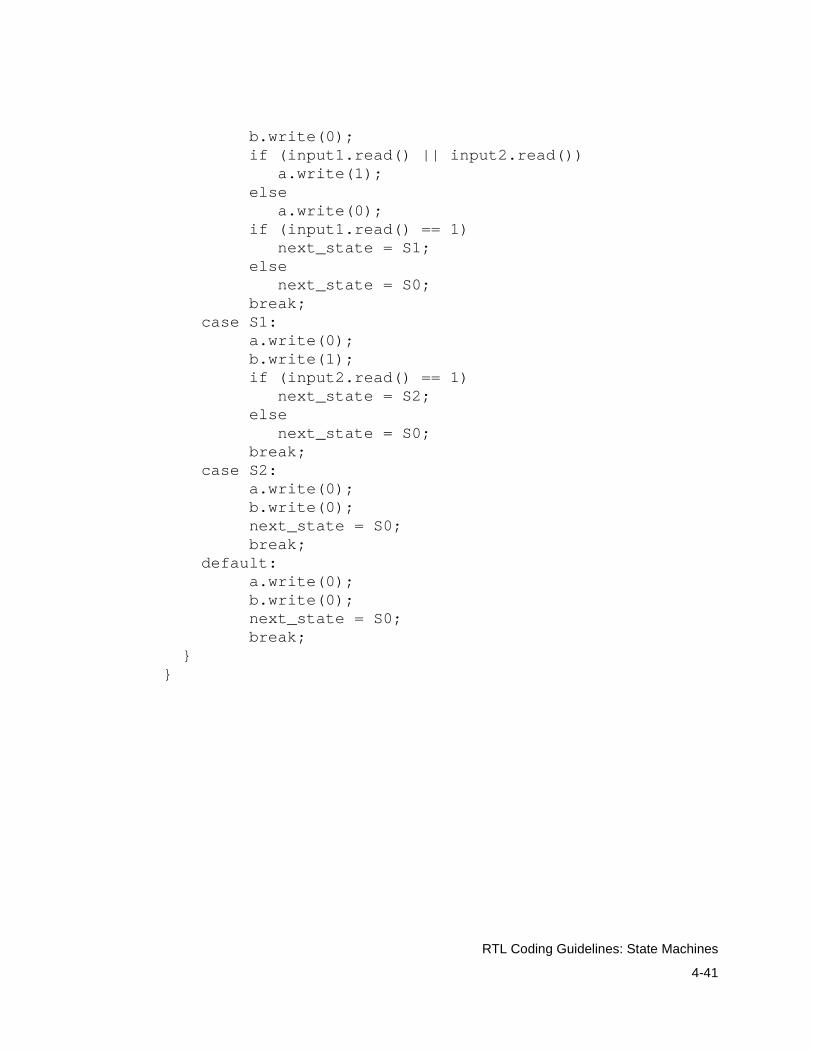
4-41
RTL Coding Guidelines: State Machines
b.write(0); if (input1.read() || input2.read()) a.write(1); else a.write(0); if (input1.read() == 1) next_state = S1; else next_state = S0; break; case S1: a.write(0); b.write(1); if (input2.read() == 1) next_state = S2; else next_state = S0; break; case S2: a.write(0); b.write(0); next_state = S0; break; default: a.write(0); b.write(0); next_state = S0; break; }}

4-42
RTL Coding Guidelines: State Machines
State Machine With Separate Computation Processes
Example 4-28 shows the state machine (represented in Figure 4-28) with separate SC_METHOD processes for computing the output and next-state logic.
Example 4-28 State Machine With Separate Computation Processes
SC_MODULE(fsm_b){ sc_in_clk clk; sc_in<bool> rst, input1, input2; sc_out<bool> a, b;
sc_signal<state_t> state, next_state;
void ns_op_logic(); void output_logic(); void update_state();
SC_CTOR(fsm_b){ SC_METHOD(update_state); sensitive_pos << clk; SC_METHOD(ns_logic); sensitive << state << input1 << input2; SC_METHOD(output_logic); sensitive << state << input1 << input2; }};
enum state_t { // enumerate states S0, S1, S2};
void fsm_b::update_state() { if (rst.read() == true) state = S0; else state = next_state;}
void fsm_b::ns_logic() { // Determine next state
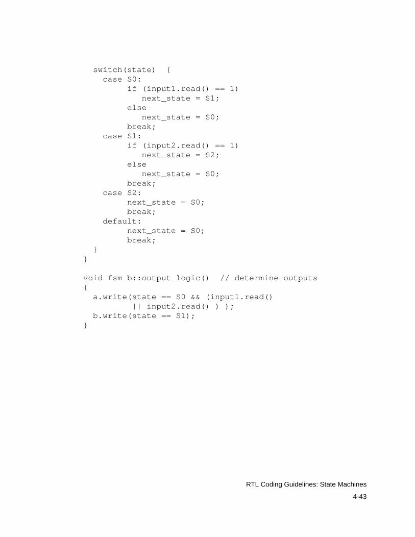
4-43
RTL Coding Guidelines: State Machines
switch(state) { case S0: if (input1.read() == 1) next_state = S1; else next_state = S0; break; case S1: if (input2.read() == 1) next_state = S2; else next_state = S0; break; case S2: next_state = S0; break; default: next_state = S0; break; }}
void fsm_b::output_logic() // determine outputs{ a.write(state == S0 && (input1.read() || input2.read() ) ); b.write(state == S1);}
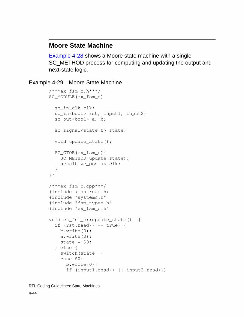
4-44
RTL Coding Guidelines: State Machines
Moore State Machine
Example 4-28 shows a Moore state machine with a single SC_METHOD process for computing and updating the output and next-state logic.
Example 4-29 Moore State Machine
/***ex_fsm_c.h***/SC_MODULE(ex_fsm_c){ sc_in_clk clk; sc_in<bool> rst, input1, input2; sc_out<bool> a, b;
sc_signal<state_t> state;
void update_state();
SC_CTOR(ex_fsm_c){ SC_METHOD(update_state); sensitive_pos << clk; }};
/***ex_fsm_c.cpp***/#include <iostream.h>#include "systemc.h"#include "fsm_types.h"#include "ex_fsm_c.h"
void ex_fsm_c::update_state() { if (rst.read() == true) { b.write(0); a.write(0); state = S0; } else { switch(state) { case S0: b.write(0); if (input1.read() || input2.read())
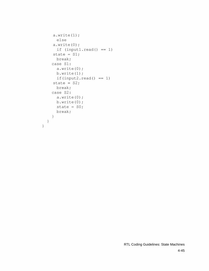
4-45
RTL Coding Guidelines: State Machines
a.write(1); else
a.write(0); if (input1.read() == 1)
state = S1; break; case S1: a.write(0); b.write(1); if(input2.read() == 1)
state = S2; break; case S2: a.write(0); b.write(0); state = S0; break; } }}

4-46
RTL Coding Guidelines: State Machines
5-1
5Behavioral Modeling and Synthesis 5
In addition to the RTL modeling style described in the previous chapters, you can use the behavioral modeling style to model synthesizable circuits at a higher level of abstraction than RTL. This chapter provides a brief introduction to SystemC behavioral modeling and behavioral synthesis. It contains the following sections:
• Comparing RTL and Behavioral Modeling
• What is Behavioral Synthesis?
• Choosing the Right Abstraction for Synthesis
• RTL and Behavioral Coding Style Examples
• Getting More Information About Behavioral Synthesis
5-2
Behavioral Modeling and Synthesis: Comparing RTL and Behavioral Modeling
Comparing RTL and Behavioral Modeling
An RTL model describes registers in your design and the combinational logic between the registers. You specify the functionality of your system as an finite state machine (FSM) and a data path. Because register updates are tied to a clock, the model is cycle accurate, both at the interfaces and internally. Internal cycle accuracy means you specify the clock cycle in which each operation is performed.
A behavioral model is a higher-level algorithmic description. You describe your design functionality, when inputs are read, the operations performed on the input data, and when the results are written to the outputs. You do not specify a finite state machine (FSM) for controlling your design or the clock cycle when each operation or I/O is executed; behavioral synthesis decides these based on constraints you provide for the design.
Your behavioral description is independent from the technology and implementation architecture. For behavioral synthesis, you can change the target technology library or constrain the implementation architecture without modifying the behavioral description. This allows you to quickly explore various architectures for your design.
Behavioral descriptions are smaller, make it easier to capture complex algorithms, are faster to simulate because of the higher level of abstraction, accommodate late specification changes, and are more intuitive to write and understand (and therefore maintain) than RTL descriptions.
5-3
Behavioral Modeling and Synthesis: What is Behavioral Synthesis?
What is Behavioral Synthesis?
Behavioral synthesis performs the following with a SystemC behavioral description:
• Times all operations according to a technology library
• Schedules each operation, input read, and output write to occur at a specified clock cycle
• Allocates synthetic components to execute the operations in your design
• Allocates registers to store the values of variables, signals, and intermediate operation results
• Creates a data path with the allocated synthetic components and registers by inserting multiplexers and interconnects as needed
• Creates a finite state machine (FSM) and memory interface control logic
The synthesized design consists of an FSM, a data path, and memory, as shown in Figure 5-1.

5-4
Behavioral Modeling and Synthesis: What is Behavioral Synthesis?
Figure 5-1 Structure of the Circuit Generated During Behavioral Synthesis
Timing
During timing, behavioral synthesis decides which component from the synthetic library it can use to implement each operation in your behavioral description and the delay through each component. Behavioral synthesis uses the basic components, the wire load models, and the operating conditions from the ASIC or FPGA vendor technology library to compute the timing.
State
O
MM
R
Output
EnableClk
Input
Input
Data Path
0 00 0 01101100101101011 00 0 01111000010101010 10 0 00111110101010111 10 0 00101010111110010 01 0 11010101110101011 01 0 00000000110101010 11 0 0111111110010111
Memory
Data
Logic
State
Control FSM
Status
optional
Externalinput
Memory
+
Control

5-5
Behavioral Modeling and Synthesis: What is Behavioral Synthesis?
Behavioral synthesis uses the timing estimates during scheduling and allocation to synthesize the most efficient implementation for your design.
Scheduling
During scheduling, behavioral synthesis decides in which clock cycle each I/O and operation will occur during execution. Scheduling is illustrated in Figure 5-2.
Figure 5-2 Scheduling Into a Specific Clock Cycle
wait_until(start.delayed() == true);A = port1.read() * port2.read();B = port3.read() * port4.read();C = A + B;if (C < 0) {...}
port1
port2
port3
port4*
A
B
C
OperationCycle
1
2
3
4
*
*
+
<
Schedule read inputs
5
I/O Arithmetic operations Scheduled operations
Behavioral code
+ <
*
5-6
Behavioral Modeling and Synthesis: What is Behavioral Synthesis?
Behavioral synthesis objectives during scheduling are to
• Satisfy the data flow and control dependencies described in the behavioral description
• Satisfy any scheduling constraints of latency, throughput, and clock period specified
• Minimize the number of clock cycles needed by the implementation to execute the specified functionality
• Facilitate resource sharing by distributing operations over the available clock cycles to minimize the implementation area
• Facilitate register sharing by intelligently producing and using data to minimize the number of registers needed
I/O between the implementation synthesized by behavioral synthesis and the external environment usually has a predefined protocol. The I/O protocol typically specifies either a fully synchronous interface with a fixed clock cycle for each input and output or a handshake-driven interface where the relative order of inputs and outputs is specified, but the clock cycle when each input and output occurs can vary. You define whether behavioral synthesis uses a fixed clock cycle or handshake-driven interface.
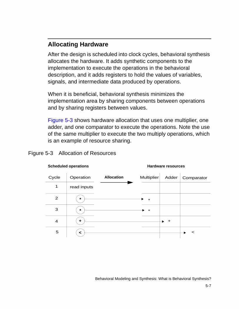
5-7
Behavioral Modeling and Synthesis: What is Behavioral Synthesis?
Allocating Hardware
After the design is scheduled into clock cycles, behavioral synthesis allocates the hardware. It adds synthetic components to the implementation to execute the operations in the behavioral description, and it adds registers to hold the values of variables, signals, and intermediate data produced by operations.
When it is beneficial, behavioral synthesis minimizes the implementation area by sharing components between operations and by sharing registers between values.
Figure 5-3 shows hardware allocation that uses one multiplier, one adder, and one comparator to execute the operations. Note the use of the same multiplier to execute the two multiply operations, which is an example of resource sharing.
Figure 5-3 Allocation of Resources
Allocation Multiplier
*
*
+
<
Hardware resources
Adder ComparatorOperationCycle
1
2
3
4
*
*
+
<
read inputs
5
Scheduled operations
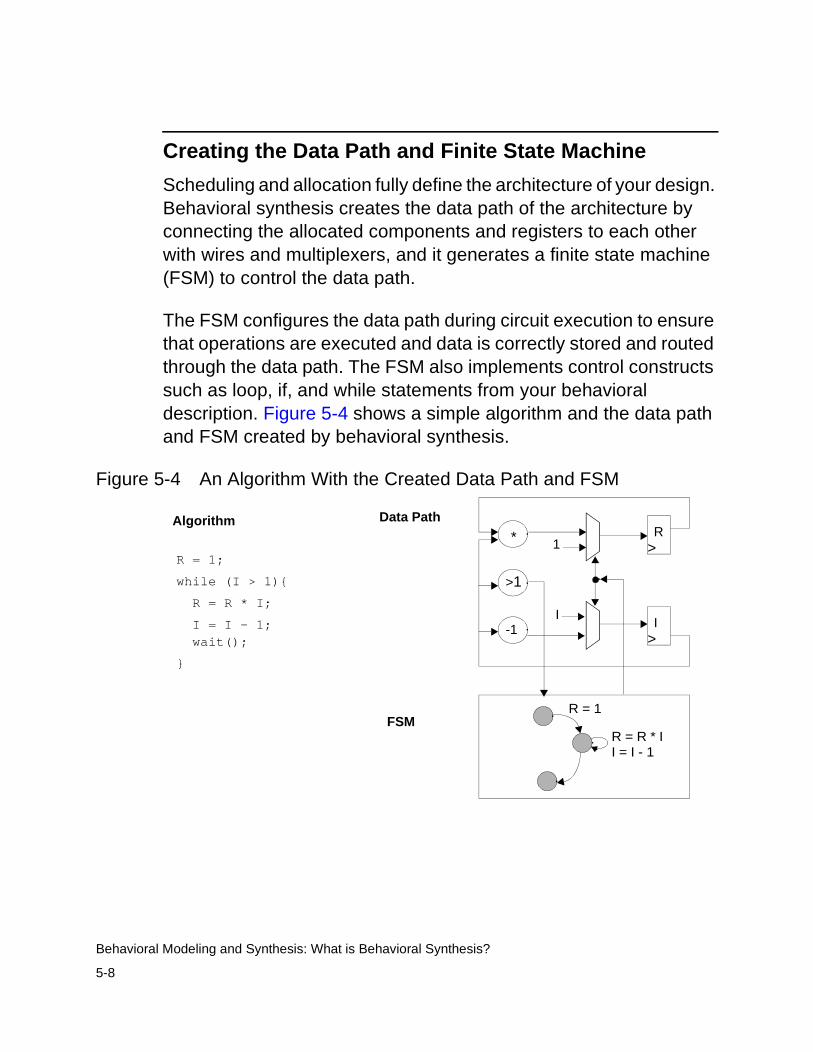
5-8
Behavioral Modeling and Synthesis: What is Behavioral Synthesis?
Creating the Data Path and Finite State Machine
Scheduling and allocation fully define the architecture of your design. Behavioral synthesis creates the data path of the architecture by connecting the allocated components and registers to each other with wires and multiplexers, and it generates a finite state machine (FSM) to control the data path.
The FSM configures the data path during circuit execution to ensure that operations are executed and data is correctly stored and routed through the data path. The FSM also implements control constructs such as loop, if, and while statements from your behavioral description. Figure 5-4 shows a simple algorithm and the data path and FSM created by behavioral synthesis.
Figure 5-4 An Algorithm With the Created Data Path and FSM
Algorithm Data Path
FSM
R = 1;
while (I > 1){
R = R * I;
I = I - 1;
}
*
>1
-1
>R
>I
I
1
R = 1
R = R * II = I - 1
wait();
5-9
Behavioral Modeling and Synthesis: Choosing the Right Abstraction for Synthesis
Choosing the Right Abstraction for Synthesis
You can implement a hardware module by using RTL synthesis or behavioral-level synthesis. Evaluate each design module by module, and consider each module’s attributes, described in the following sections, to determine whether RTL or behavioral synthesis is applicable.
Identifying Attributes Suitable for RTL Synthesis
Look for the following design attributes when identifying a hardware module that is suitable for RTL synthesis:
• It is easier to conceive the design as an FSM and a data path than as an algorithm—for example, a microprocessor.
• The design is very high-performance, and the designer, therefore, needs complete control over the architecture.
• The design contains complex memory such as SDRAM or RAMBUS.
• The design is asynchronous.
5-10
Behavioral Modeling and Synthesis: Choosing the Right Abstraction for Synthesis
Identifying Attributes Suitable for Behavioral Synthesis
Look for the following design attributes when identifying a hardware module that is suitable for behavioral synthesis:
• It is easier to conceive the design as an algorithm than as an FSM and a data path—for example, a fast Fourier transform, filter, inverse quantization, or digital signal processor.
• The design has a complex control flow—for example, a network processor.
• The design has memory accesses, and you need to synthesize access to synchronous memory.
Applications that are suitable for behavioral modeling and synthesis are
• Digital communication applications such as cable modems, cellular phones, cordless phones, two-way pagers, wireless LANs, satellite DSPs, and XDSL modems
• Image and video processing applications such as digital cameras, printers, set-top boxes, 3-D graphic devices, and video capture devices
• Networking applications such as ATM switches, fast networking switches, and packet routers
• Digital signal processing applications such as filters, codecs, IQ, IDCT, and channel equalizers
• Computer applications such as cache controllers, hardware accelerators, and fixed-point arithmetic units

5-11
Behavioral Modeling and Synthesis: Choosing the Right Abstraction for Synthesis
Benefits of Behavioral Synthesis
The following are benefits of behavioral synthesis compared to RTL synthesis:
A behavioral description
• Promotes communication of design intent
• Is smaller than RTL code
• Promotes greater design reuse, because the design is technology- and architecture-independent
• Accommodates late design specification changes, because the code is architecture-independent
• Cuts implementation time significantly, increasing designer productivity
• Increases verification speed and decreases verification time
• Promotes exploration of alternative architectures
• Automatically creates the control FSM and data path
• Pipelines critical parts of the design such as loops
• Shares components and registers
• Automatically synthesizes synchronous memory accesses
5-12
Behavioral Modeling and Synthesis: RTL and Behavioral Coding Style Examples
RTL and Behavioral Coding Style Examples
This section provides an RTL description and a behavioral description for a FIFO. The FIFO is a circular buffer that accepts a 32-bit integer value from the input and writes an integer to the output. The reset port clears all data in the buffer.
The RTL description shows the level of detail you need in order to describe an RTL model, which is automatically created during behavioral synthesis from the behavioral description.
RTL Coding Style
The general characteristics of the RTL coding style for synthesis are the following:
• Implements the design as combinational logic between registers. The finite state machine and the data path are explicitly specified.
• Uses only the synthesizable SystemC data types
• Uses the synthesizable subset of the C++ language
Example 5-1 is an RTL version of the FIFO behavioral model in Example 5-2. The RTL coding style has separate processes for the FSM control and data path. Notice that the RTL version of the FIFO is much longer and more detailed than the equivalent behavioral version and that it is harder to follow than the behavioral description.
5-13
Behavioral Modeling and Synthesis: RTL and Behavioral Coding Style Examples
Example 5-1 RTL Coding
/* fifo_rtl.h header file */
#define BUFSIZE 4#define LOGBUFSIZE 2#define LOGBUFSIZEPLUSONE 3
SC_MODULE(circ_buf) { // Same I/O as behavioral sc_in<bool> clk; sc_in<bool> read_fifo; sc_in<bool> write_fifo; sc_in<int> data_in; sc_in<bool> reset; sc_out<int> data_out; sc_out<bool> full; sc_out<bool> empty;
// Internal signals sc_signal<int> buf0, buf0_next; sc_signal<int> buf1, buf1_next; sc_signal<int> buf2, buf2_next; sc_signal<int> buf3, buf3_next; sc_signal<sc_uint<LOGBUFSIZEPLUSONE> > num_in_buf, num_in_buf_next; sc_signal<bool> full_next, empty_next; sc_signal<int> data_out_next;
// Declare processes void ns_logic(); // Next-state logic void update_regs();// Update all registers void gen_full(); // Generate a full signal void gen_empty(); // Generate an empty signal
// Constructor SC_CTOR(circ_buf) {
SC_METHOD(ns_logic);sensitive << read_fifo << write_fifo
<< data_in << num_in_buf;
SC_METHOD(update_regs);sensitive_pos << clk;
SC_METHOD(gen_full);sensitive << num_in_buf_next;
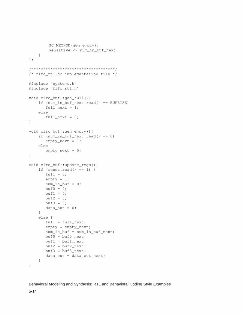
5-14
Behavioral Modeling and Synthesis: RTL and Behavioral Coding Style Examples
SC_METHOD(gen_empty);sensitive << num_in_buf_next;
}};
/***********************************//* fifo_rtl.cc implementation file */
#include "systemc.h"#include "fifo_rtl.h"
void circ_buf::gen_full(){ if (num_in_buf_next.read() == BUFSIZE) full_next = 1; else full_next = 0;}
void circ_buf::gen_empty(){ if (num_in_buf_next.read() == 0) empty_next = 1; else empty_next = 0;}
void circ_buf::update_regs(){ if (reset.read() == 1) { full = 0; empty = 1; num_in_buf = 0; buf0 = 0; buf1 = 0; buf2 = 0; buf3 = 0; data_out = 0; } else { full = full_next; empty = empty_next; num_in_buf = num_in_buf_next; buf0 = buf0_next; buf1 = buf1_next; buf2 = buf2_next; buf3 = buf3_next; data_out = data_out_next; }}
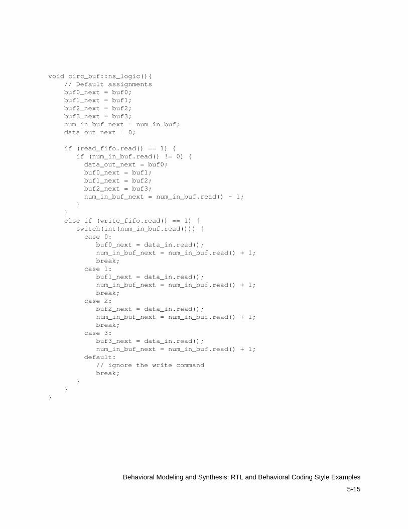
5-15
Behavioral Modeling and Synthesis: RTL and Behavioral Coding Style Examples
void circ_buf::ns_logic(){ // Default assignments buf0_next = buf0; buf1_next = buf1; buf2_next = buf2; buf3_next = buf3; num_in_buf_next = num_in_buf; data_out_next = 0;
if (read_fifo.read() == 1) { if (num_in_buf.read() != 0) { data_out_next = buf0; buf0_next = buf1; buf1_next = buf2; buf2_next = buf3; num_in_buf_next = num_in_buf.read() - 1; } } else if (write_fifo.read() == 1) { switch(int(num_in_buf.read())) { case 0: buf0_next = data_in.read(); num_in_buf_next = num_in_buf.read() + 1; break; case 1: buf1_next = data_in.read(); num_in_buf_next = num_in_buf.read() + 1; break; case 2: buf2_next = data_in.read(); num_in_buf_next = num_in_buf.read() + 1; break; case 3: buf3_next = data_in.read(); num_in_buf_next = num_in_buf.read() + 1; default: // ignore the write command break; } }}
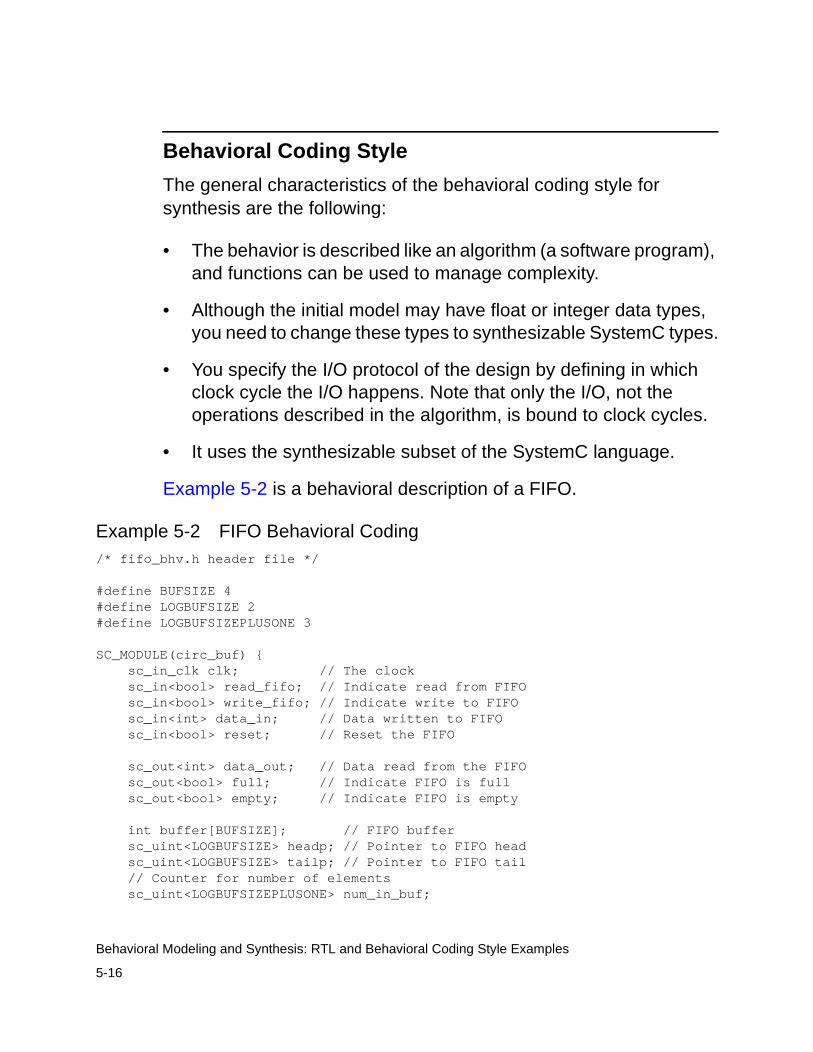
5-16
Behavioral Modeling and Synthesis: RTL and Behavioral Coding Style Examples
Behavioral Coding Style
The general characteristics of the behavioral coding style for synthesis are the following:
• The behavior is described like an algorithm (a software program), and functions can be used to manage complexity.
• Although the initial model may have float or integer data types, you need to change these types to synthesizable SystemC types.
• You specify the I/O protocol of the design by defining in which clock cycle the I/O happens. Note that only the I/O, not the operations described in the algorithm, is bound to clock cycles.
• It uses the synthesizable subset of the SystemC language.
Example 5-2 is a behavioral description of a FIFO.
Example 5-2 FIFO Behavioral Coding/* fifo_bhv.h header file */
#define BUFSIZE 4#define LOGBUFSIZE 2#define LOGBUFSIZEPLUSONE 3
SC_MODULE(circ_buf) { sc_in_clk clk; // The clock sc_in<bool> read_fifo; // Indicate read from FIFO sc_in<bool> write_fifo; // Indicate write to FIFO sc_in<int> data_in; // Data written to FIFO sc_in<bool> reset; // Reset the FIFO
sc_out<int> data_out; // Data read from the FIFO sc_out<bool> full; // Indicate FIFO is full sc_out<bool> empty; // Indicate FIFO is empty
int buffer[BUFSIZE]; // FIFO buffer sc_uint<LOGBUFSIZE> headp; // Pointer to FIFO head sc_uint<LOGBUFSIZE> tailp; // Pointer to FIFO tail // Counter for number of elements sc_uint<LOGBUFSIZEPLUSONE> num_in_buf;

5-17
Behavioral Modeling and Synthesis: RTL and Behavioral Coding Style Examples
void read_write(); // FIFO process
SC_CTOR(circ_buf) { SC_CTHREAD(read_write, clk.pos()); watching(reset.delayed() == true); }};
/***********************************/ /* fifo_bhv.cc implementation file */
#include "systemc.h"#include "fifo_bhv.h"
voidcirc_buf::read_write(){ // Reset operations headp = 0; tailp = 0; num_in_buf = 0; full = false; empty = true; data_out = 0; for (int i = 0; i < BUFSIZE; i++){ /* synopsys unroll */ buffer[i] = 0; } wait();
// Main loop while (true) {
if (read_fifo.read()) {
// Check if FIFO is not empty if (num_in_buf != 0) { num_in_buf--; data_out = buffer[headp++]; full = false; if (num_in_buf == 0) empty = true; } // Ignore read request otherwise } else if (write_fifo.read()) {
// Check if FIFO is not full if (num_in_buf != BUFSIZE) {
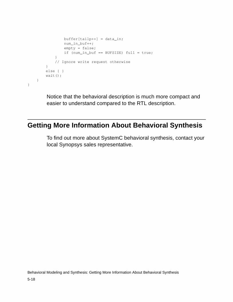
5-18
Behavioral Modeling and Synthesis: Getting More Information About Behavioral Synthesis
buffer[tailp++] = data_in; num_in_buf++; empty = false; if (num_in_buf == BUFSIZE) full = true; } // Ignore write request otherwise } else { } wait(); }}
Notice that the behavioral description is much more compact and easier to understand compared to the RTL description.
Getting More Information About Behavioral Synthesis
To find out more about SystemC behavioral synthesis, contact your local Synopsys sales representative.