Embed Size (px)
Citation preview
HYDRAULICS AND PNEUMATICS www.bookspar.com |VTU NOTES |QUESTION PAPERS |NEWS |RESULTS |FORUM
www.bookspar.com |VTU NOTES |QUESTION PAPERS |NEWS |RESULTS |FORUM
Chapter 4: Control components in Hydraulic system
One of the most important functions in any fluid power system is control. If control components are not properly selected, the entire system will fail to deliver the required output. Elements for the control of energy and other control in fluid power system are generally called “Valves”. It is important to know the primary function and operation of the various types of control components. This type of knowledge is not only required for a good functioning system, but it also leads to the discovery of innovative ways to improve a fluid power system for a given application
The selection of these control components not only involves the type, but also the size, the actuating method and remote control capability. There are 3 basic types of valves.
1. Directional control valves
1. Pressure control valves
2. Flow control valves.
Directional control valves are essentially used for distribution of energy in a fluid power system. They establish the path through which a fluid traverses a given circuit. For example they control the direction of motion of a hydraulic cylinder or motor. These valves are used to control the start, stop and change in direction of flow of pressurized fluid.
Pressure may gradually buildup due to decrease in fluid demand or due to sudden surge as valves opens or closes. Pressure control valves protect the system against such overpressure. Pressure relief valve, pressure reducing, sequence, unloading and counterbalance valve are different types of pressure control valves.
In addition, fluid flow rate must be controlled in various lines of a hydraulic circuit. For example, the control of actuator speeds depends on flow rates. This type of control is accomplished through the use of flow control valves.
Directional control valves
As the name implies directional control valves are used to control the direction of flow in a hydraulic circuit. They are used to extend, retract, position or reciprocate hydraulic cylinder and other components for linear motion. Valves contains ports that are external openings for fluid to enter and leave via connecting pipelines, The number of ports on a directional control valve (DCV ) is usually identified by the term “ way”. For example, a valve with four ports is named as four-way valve.
Directional control valves can be classified in a number of ways:
HYDRAULICS AND PNEUMATICS www.bookspar.com |VTU NOTES |QUESTION PAPERS |NEWS |RESULTS |FORUM
www.bookspar.com |VTU NOTES |QUESTION PAPERS |NEWS |RESULTS |FORUM
1. According to type of construction :
• Poppet valves
• Spool valves
2. According to number of working ports :
• Two- way valves
• Three – way valves
• Four- way valves.
3. According to number of Switching position:
• Two – position
• Three - position
4. According to Actuating mechanism:
• Manual actuation
• Mechanical actuation
• Solenoid ( Electrical ) actuation
• Hydraulic ( Pilot ) actuation
• Pneumatic actuation
• Indirect actuation
The designation of the directional control valve refers to the number of working ports and the number of switching positions.
Thus a valve with 2 service ports and 2 switching positions is designated as 2 / 2 way valve. A
P
Fig 4.1. 2 /2 valve symbol
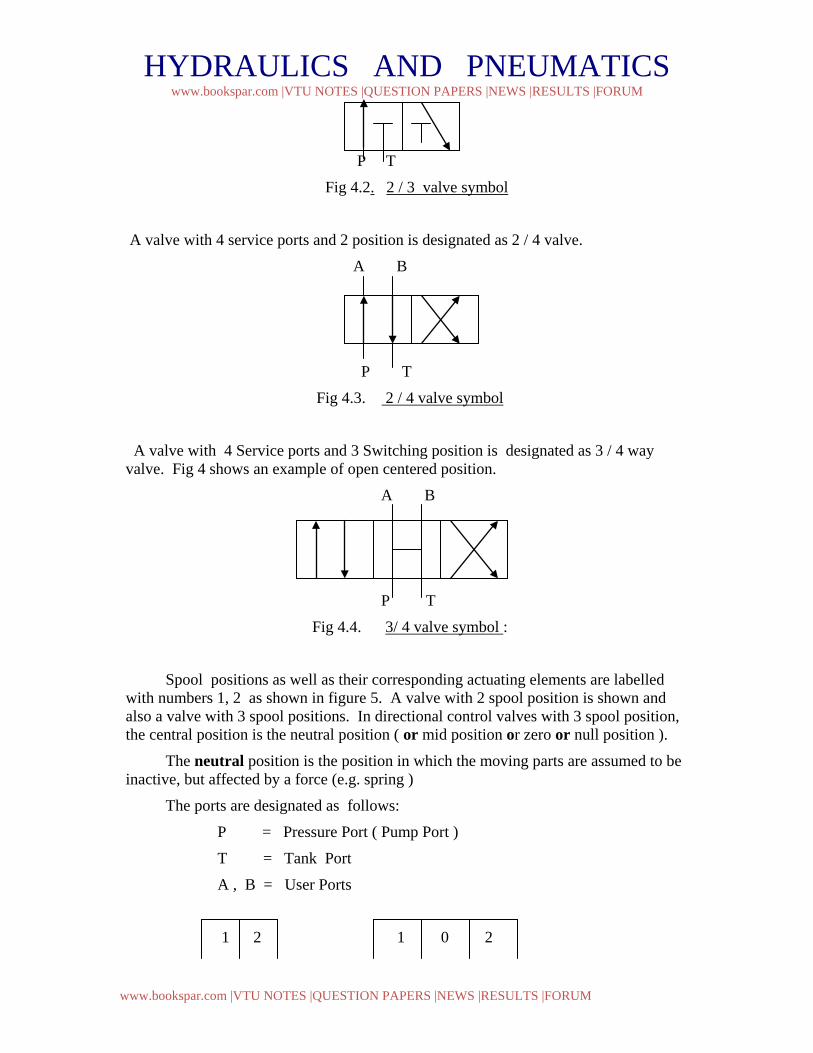
A valve with 3 service ports and 2 position is designated as 2 / 3 way valve.
A
HYDRAULICS AND PNEUMATICS www.bookspar.com |VTU NOTES |QUESTION PAPERS |NEWS |RESULTS |FORUM
www.bookspar.com |VTU NOTES |QUESTION PAPERS |NEWS |RESULTS |FORUM
P T
Fig 4.2. 2 / 3 valve symbol
A valve with 4 service ports and 2 position is designated as 2 / 4 valve.
A B
P T
Fig 4.3. 2 / 4 valve symbol
A valve with 4 Service ports and 3 Switching position is designated as 3 / 4 way valve. Fig 4 shows an example of open centered position.
A B
P T
Fig 4.4. 3/ 4 valve symbol :
Spool positions as well as their corresponding actuating elements are labelled with numbers 1, 2 as shown in figure 5. A valve with 2 spool position is shown and also a valve with 3 spool positions. In directional control valves with 3 spool position, the central position is the neutral position ( or mid position or zero or null position ).
The neutral position is the position in which the moving parts are assumed to be inactive, but affected by a force (e.g. spring )
The ports are designated as follows:
P = Pressure Port ( Pump Port )
T = Tank Port
A , B = User Ports
1 2 1 0 2
HYDRAULICS AND PNEUMATICS www.bookspar.com |VTU NOTES |QUESTION PAPERS |NEWS |RESULTS |FORUM
www.bookspar.com |VTU NOTES |QUESTION PAPERS |NEWS |RESULTS |FORUM
2- Position valve 3- Position valve
Fig 4.5. Basic symbol for directional control valves
Observe that the graphical symbol shows only one tank port T even though the physical design may have two since it is only concerned with the function of a component and not its internal design. The tank port is the port of the valve that is piped back to the hydraulic oil tank. Therefore, each tank port provides the same function. The spool valve working ports are inlet from the pump, outlets to the cylinder, and exhaust to tank. These ports are generally identified as follows : P = pressure ; A or B = actuator and T = tank.
1. Poppet Valves: Directional poppet valves consists of a housing bore in which one or more suitably formed seating elements ( moveable ) in the form of balls, cones are situated. When the operating pressure increases the valve becomes more tightly seated in this design. The main advantage of poppet valves are;
- No Leakage as it provides absolute sealing.
- Long useful life, as there are no leakage of oil flows.
- May be used with even the highest pressures, as no hydraulic sticking (pressure dependent deformation ) and leakages occurs in the valve.
The disadvantages of these valves are;
- Large pressure losses due to short strokes
- Pressure collapse during switching phase due to negative overlap ( connection of pump, actuator and tank at the same time ).
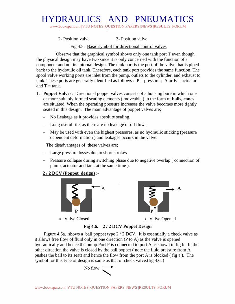
2 / 2 DCV (Poppet design) :-
A A
P P a. Valve Closed b. Valve Opened
Fig 4.6. 2 / 2 DCV Poppet Design Figure 4.6a. shows a ball poppet type 2 / 2 DCV. It is essentially a check valve as it allows free flow of fluid only in one direction (P to A) as the valve is opened hydraulically and hence the pump Port P is connected to port A as shown in fig b. In the other direction the valve is closed by the ball poppet ( note the fluid pressure from A pushes the ball to its seat) and hence the flow from the port A is blocked ( fig a.). The symbol for this type of design is same as that of check valve.(fig 4.6c)
No flow
HYDRAULICS AND PNEUMATICS www.bookspar.com |VTU NOTES |QUESTION PAPERS |NEWS |RESULTS |FORUM
www.bookspar.com |VTU NOTES |QUESTION PAPERS |NEWS |RESULTS |FORUM
Free flow
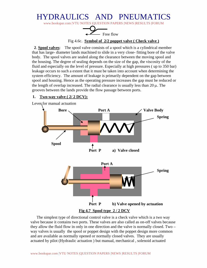
Fig 4.6c. Symbol of 2/2 poppet valve ( Check valve ) 2. Spool valves: The spool valve consists of a spool which is a cylindrical member that has large- diameter lands machined to slide in a very close- fitting bore of the valve body. The spool valves are sealed along the clearance between the moving spool and the housing. The degree of sealing depends on the size of the gap, the viscosity of the fluid and especially on the level of pressure. Especially at high pressures ( up to 350 bar) leakage occurs to such a extent that it must be taken into account when determining the system efficiency. The amount of leakage is primarily dependent on the gap between spool and housing. Hence as the operating pressure increases the gap must be reduced or the length of overlap increased. The radial clearance is usually less than 20 µ. The grooves between the lands provide the flow passage between ports.
1. Two-way valve ( 2/ 2 DCV): Lever for manual actuation
Bore Port A Valve Body Spring
Spool Port P a) Valve closed
Port A Spring
Port P b) Valve opened by actuation Fig 4.7 Spool type 2 / 2 DCV
The simplest type of directional control valve is a check valve which is a two way valve because it contains two ports. These valves are also called as on-off valves because they allow the fluid flow in only in one direction and the valve is normally closed. Two – way valves is usually the spool or poppet design with the poppet design more common and are available as normally opened or normally closed valves. They are usually actuated by pilot (Hydraulic actuation ) but manual, mechanical , solenoid actuated
HYDRAULICS AND PNEUMATICS www.bookspar.com |VTU NOTES |QUESTION PAPERS |NEWS |RESULTS |FORUM
www.bookspar.com |VTU NOTES |QUESTION PAPERS |NEWS |RESULTS |FORUM
design are also available. Figure 4.7 above shows Spool type 2 / 2 DCV manually actuated. In Fig 4.7 a) the port P is blocked by the action of spring as the valve is unactuated ( absence of hand force). Hence the flow from port P to A is blocked. When actuated ( Presence of hand force ) the valve is opened, thereby connecting port P to A.
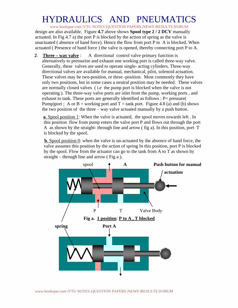
2. Three – way valve : A directional control valve primary function is alternatively to pressurize and exhaust one working port is called three-way valve. Generally, these valves are used to operate single- acting cylinders. Three-way directional valves are available for manual, mechanical, pilot, solenoid actuation. These valves may be two-position, or three -position. Most commonly they have only two positions, but in some cases a neutral position may be needed. These valves are normally closed valves ( i.e the pump port is blocked when the valve is not operating ). The three-way valve ports are inlet from the pump, working ports , and exhaust to tank. These ports are generally identified as follows : P= pressure( Pump)port ; A or B = working port and T = tank port. Figure 4.8 (a) and (b) shows the two position of the three – way valve actuated manually by a push button.
a. Spool position 1: When the valve is actuated, the spool moves towards left . In this position flow from pump enters the valve port P and flows out through the port A as shown by the straight- through line and arrow ( fig a). In this position, port T is blocked by the spool.
b. Spool position 0: when the valve is un-actuated by the absence of hand force, the valve assumes this position by the action of spring In this position, port P is blocked by the spool. Flow from the actuator can go to the tank from A to T as shown by straight – through line and arrow ( Fig a ).
spool A Push button for manual
actuation
P T Valve Body
Fig a. 1 position: P to A , T blocked
spring Port A
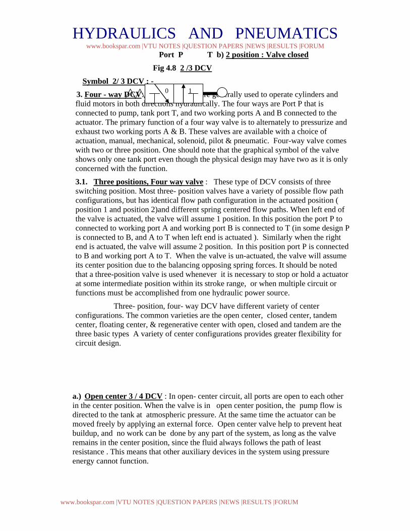
HYDRAULICS AND PNEUMATICS www.bookspar.com |VTU NOTES |QUESTION PAPERS |NEWS |RESULTS |FORUM
www.bookspar.com |VTU NOTES |QUESTION PAPERS |NEWS |RESULTS |FORUM
Port P T b) 2 position : Valve closed
Fig 4.8 2 /3 DCV
Symbol 2/ 3 DCV : - 3. Four - way DCV: - These valves are generally used to operate cylinders and
fluid motors in both directions hydraulically. The four ways are Port P that is connected to pump, tank port T, and two working ports A and B connected to the actuator. The primary function of a four way valve is to alternately to pressurize and exhaust two working ports A & B. These valves are available with a choice of actuation, manual, mechanical, solenoid, pilot & pneumatic. Four-way valve comes with two or three position. One should note that the graphical symbol of the valve shows only one tank port even though the physical design may have two as it is only concerned with the function.
3.1. Three positions, Four way valve : These type of DCV consists of three switching position. Most three- position valves have a variety of possible flow path configurations, but has identical flow path configuration in the actuated position ( position 1 and position 2)and different spring centered flow paths. When left end of the valve is actuated, the valve will assume 1 position. In this position the port P to connected to working port A and working port B is connected to T (in some design P is connected to B, and A to T when left end is actuated ). Similarly when the right end is actuated, the valve will assume 2 position. In this position port P is connected to B and working port A to T. When the valve is un-actuated, the valve will assume its center position due to the balancing opposing spring forces. It should be noted that a three-position valve is used whenever it is necessary to stop or hold a actuator at some intermediate position within its stroke range, or when multiple circuit or functions must be accomplished from one hydraulic power source.
Three- position, four- way DCV have different variety of center configurations. The common varieties are the open center, closed center, tandem center, floating center, & regenerative center with open, closed and tandem are the three basic types A variety of center configurations provides greater flexibility for circuit design.
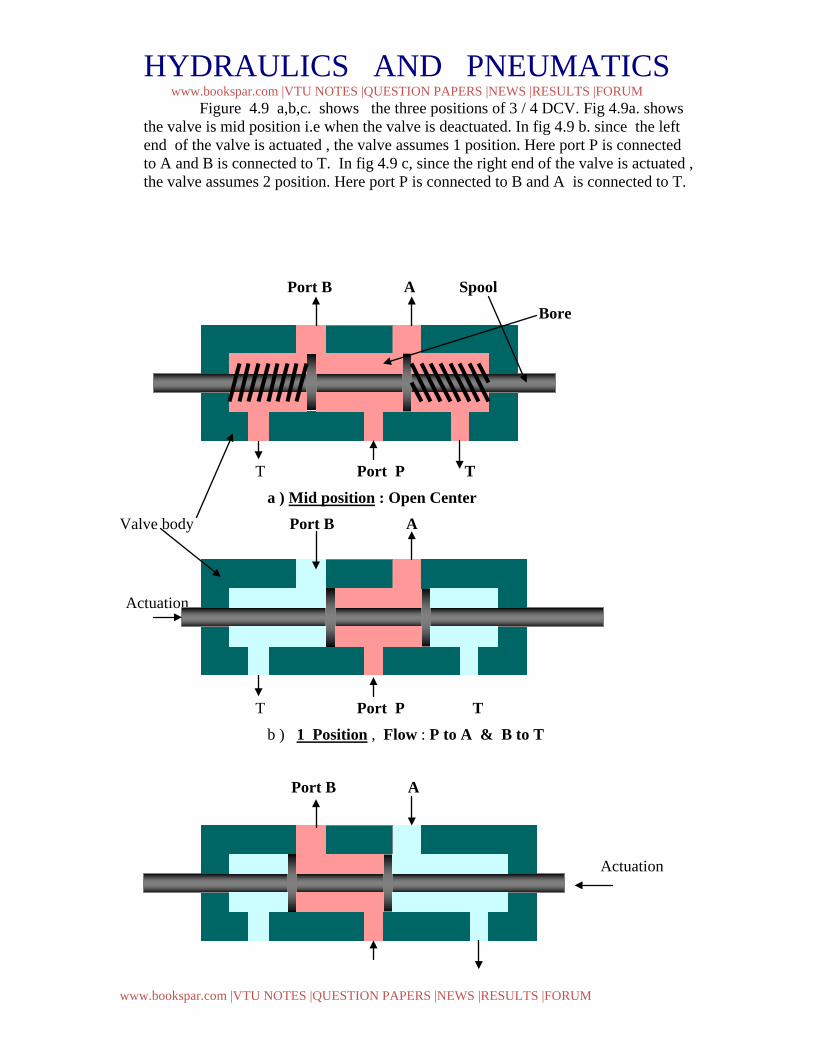
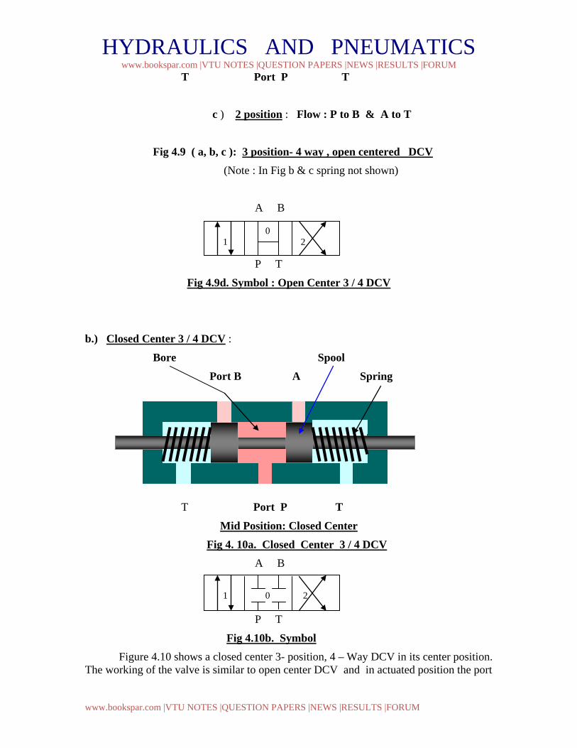
a.) Open center 3 / 4 DCV : In open- center circuit, all ports are open to each other in the center position. When the valve is in open center position, the pump flow is directed to the tank at atmospheric pressure. At the same time the actuator can be moved freely by applying an external force. Open center valve help to prevent heat buildup, and no work can be done by any part of the system, as long as the valve remains in the center position, since the fluid always follows the path of least resistance . This means that other auxiliary devices in the system using pressure energy cannot function.
0 1
HYDRAULICS AND PNEUMATICS www.bookspar.com |VTU NOTES |QUESTION PAPERS |NEWS |RESULTS |FORUM
www.bookspar.com |VTU NOTES |QUESTION PAPERS |NEWS |RESULTS |FORUM
Figure 4.9 a,b,c. shows the three positions of 3 / 4 DCV. Fig 4.9a. shows the valve is mid position i.e when the valve is deactuated. In fig 4.9 b. since the left end of the valve is actuated , the valve assumes 1 position. Here port P is connected to A and B is connected to T. In fig 4.9 c, since the right end of the valve is actuated , the valve assumes 2 position. Here port P is connected to B and A is connected to T.
Port B A Spool Bore
T Port P T
a ) Mid position : Open Center Valve body Port B A
Actuation
T Port P T b ) 1 Position , Flow : P to A & B to T
Port B A
Actuation
HYDRAULICS AND PNEUMATICS www.bookspar.com |VTU NOTES |QUESTION PAPERS |NEWS |RESULTS |FORUM
www.bookspar.com |VTU NOTES |QUESTION PAPERS |NEWS |RESULTS |FORUM
T Port P T c ) 2 position : Flow : P to B & A to T
Fig 4.9 ( a, b, c ): 3 position- 4 way , open centered DCV (Note : In Fig b & c spring not shown)
A B
P T
Fig 4.9d. Symbol : Open Center 3 / 4 DCV
b.) Closed Center 3 / 4 DCV :
Bore Spool Port B A Spring
T Port P T
Mid Position: Closed Center Fig 4. 10a. Closed Center 3 / 4 DCV A B
P T
Fig 4.10b. Symbol Figure 4.10 shows a closed center 3- position, 4 – Way DCV in its center position. The working of the valve is similar to open center DCV and in actuated position the port
0 1 2
1 0 2
HYDRAULICS AND PNEUMATICS www.bookspar.com |VTU NOTES |QUESTION PAPERS |NEWS |RESULTS |FORUM
www.bookspar.com |VTU NOTES |QUESTION PAPERS |NEWS |RESULTS |FORUM
connection is identical. In closed center DCV all ports are closed to each other. Hence the actuator connected to ports A and B is hydraulically locked and cannot be moved by an external force In this position the pump flow must go over the relief valve when flow is not being used for any other parts of the circuit. This forces the pump to produce flow at the high pressure setting of the pressure relief valve. This not only waste pump design power but promotes wear and shortens pump life. Also the temperature of oil is raised due to heat buildup in the system. This promotes oil oxidation , viscosity drop, which further raises the wear of parts and increased leakage. With this type of center in DCV, when the valve actuates to switching position 1 or 2, two things may happen. If pressure port ( P to working port A or B) opens first pressure in the system raises which is not desirable, and if tank port open first pressure drops. Closed –center versions are used only when multiple circuit or functions must be accomplished in the system from one power source.
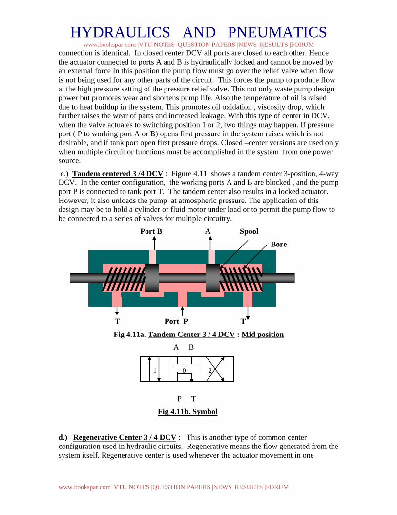
c.) Tandem centered 3 /4 DCV : Figure 4.11 shows a tandem center 3-position, 4-way DCV. In the center configuration, the working ports A and B are blocked , and the pump port P is connected to tank port T. The tandem center also results in a locked actuator. However, it also unloads the pump at atmospheric pressure. The application of this design may be to hold a cylinder or fluid motor under load or to permit the pump flow to be connected to a series of valves for multiple circuitry.
Port B A Spool Bore
T Port P T
Fig 4.11a. Tandem Center 3 / 4 DCV : Mid position A B
P T
Fig 4.11b. Symbol d.) Regenerative Center 3 / 4 DCV : This is another type of common center configuration used in hydraulic circuits. Regenerative means the flow generated from the system itself. Regenerative center is used whenever the actuator movement in one
1 0 2
HYDRAULICS AND PNEUMATICS www.bookspar.com |VTU NOTES |QUESTION PAPERS |NEWS |RESULTS |FORUM
www.bookspar.com |VTU NOTES |QUESTION PAPERS |NEWS |RESULTS |FORUM
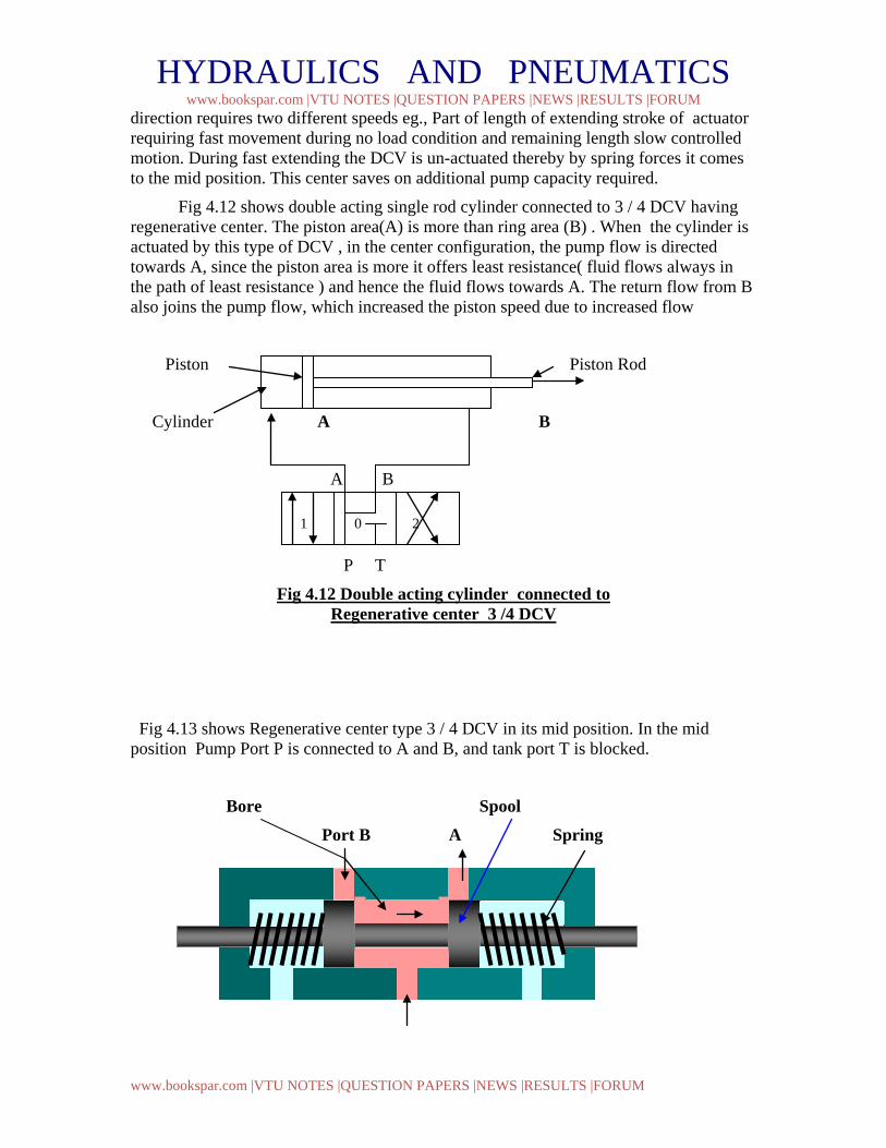
direction requires two different speeds eg., Part of length of extending stroke of actuator requiring fast movement during no load condition and remaining length slow controlled motion. During fast extending the DCV is un-actuated thereby by spring forces it comes to the mid position. This center saves on additional pump capacity required.
Fig 4.12 shows double acting single rod cylinder connected to 3 / 4 DCV having regenerative center. The piston area(A) is more than ring area (B) . When the cylinder is actuated by this type of DCV , in the center configuration, the pump flow is directed towards A, since the piston area is more it offers least resistance( fluid flows always in the path of least resistance ) and hence the fluid flows towards A. The return flow from B also joins the pump flow, which increased the piston speed due to increased flow
Piston Piston Rod
Cylinder A B
A B
P T
Fig 4.12 Double acting cylinder connected to Regenerative center 3 /4 DCV
Fig 4.13 shows Regenerative center type 3 / 4 DCV in its mid position. In the mid position Pump Port P is connected to A and B, and tank port T is blocked.
Bore Spool Port B A Spring
1 0 2
HYDRAULICS AND PNEUMATICS www.bookspar.com |VTU NOTES |QUESTION PAPERS |NEWS |RESULTS |FORUM
www.bookspar.com |VTU NOTES |QUESTION PAPERS |NEWS |RESULTS |FORUM
T Port P T
Mid Position Fig 4. 13a. Regenerative Center 3 / 4 DCV A B
:
P T
Fig 4.13b. Symbol
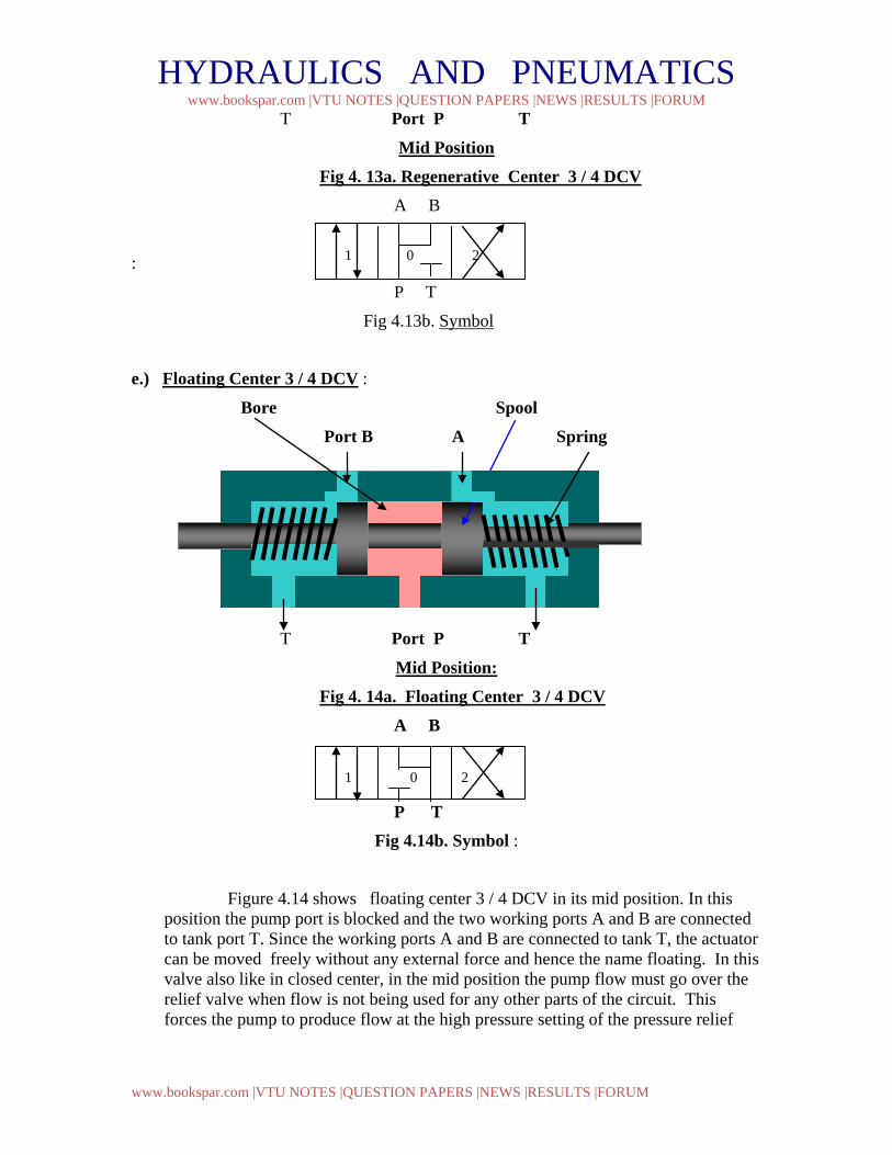
e.) Floating Center 3 / 4 DCV :
Bore Spool Port B A Spring
T Port P T
Mid Position: Fig 4. 14a. Floating Center 3 / 4 DCV A B
P T Fig 4.14b. Symbol :
Figure 4.14 shows floating center 3 / 4 DCV in its mid position. In this position the pump port is blocked and the two working ports A and B are connected to tank port T. Since the working ports A and B are connected to tank T, the actuator can be moved freely without any external force and hence the name floating. In this valve also like in closed center, in the mid position the pump flow must go over the relief valve when flow is not being used for any other parts of the circuit. This forces the pump to produce flow at the high pressure setting of the pressure relief
1 0 2
1 0 2
HYDRAULICS AND PNEUMATICS www.bookspar.com |VTU NOTES |QUESTION PAPERS |NEWS |RESULTS |FORUM
www.bookspar.com |VTU NOTES |QUESTION PAPERS |NEWS |RESULTS |FORUM
valve, which buildsup heat in the circuit. Hence this center configuration is used only in special case.
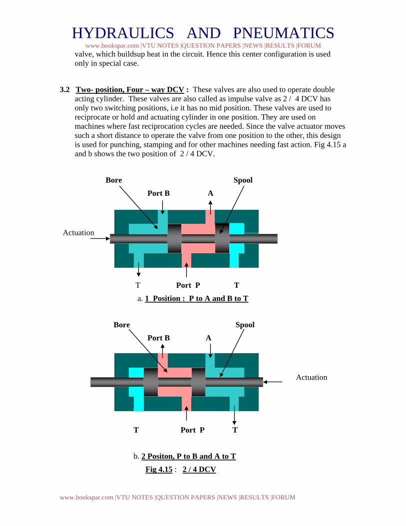
3.2 Two- position, Four – way DCV : These valves are also used to operate double acting cylinder. These valves are also called as impulse valve as 2 / 4 DCV has only two switching positions, i.e it has no mid position. These valves are used to reciprocate or hold and actuating cylinder in one position. They are used on machines where fast reciprocation cycles are needed. Since the valve actuator moves such a short distance to operate the valve from one position to the other, this design is used for punching, stamping and for other machines needing fast action. Fig 4.15 a and b shows the two position of 2 / 4 DCV.
Bore Spool Port B A
Actuation
T Port P T a. 1 Position : P to A and B to T
Bore Spool Port B A
Actuation
T Port P T
b. 2 Positon, P to B and A to T
Fig 4.15 : 2 / 4 DCV
HYDRAULICS AND PNEUMATICS www.bookspar.com |VTU NOTES |QUESTION PAPERS |NEWS |RESULTS |FORUM
www.bookspar.com |VTU NOTES |QUESTION PAPERS |NEWS |RESULTS |FORUM
11
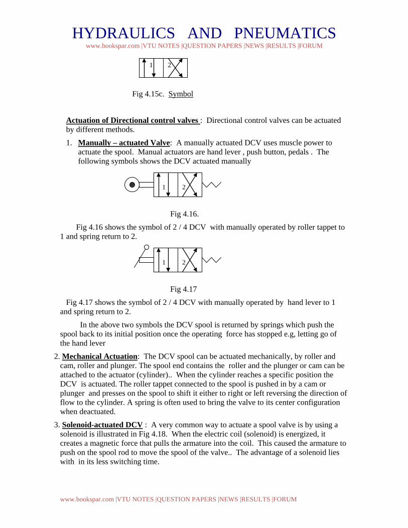
Fig 4.15c. Symbol
Actuation of Directional control valves : Directional control valves can be actuated by different methods.
1. Manually – actuated Valve: A manually actuated DCV uses muscle power to actuate the spool. Manual actuators are hand lever , push button, pedals . The following symbols shows the DCV actuated manually
Fig 4.16.
Fig 4.16 shows the symbol of 2 / 4 DCV with manually operated by roller tappet to 1 and spring return to 2.
Fig 4.17
Fig 4.17 shows the symbol of 2 / 4 DCV with manually operated by hand lever to 1 and spring return to 2.
In the above two symbols the DCV spool is returned by springs which push the spool back to its initial position once the operating force has stopped e.g, letting go of the hand lever
2. Mechanical Actuation: The DCV spool can be actuated mechanically, by roller and cam, roller and plunger. The spool end contains the roller and the plunger or cam can be attached to the actuator (cylinder).. When the cylinder reaches a specific position the DCV is actuated. The roller tappet connected to the spool is pushed in by a cam or plunger and presses on the spool to shift it either to right or left reversing the direction of flow to the cylinder. A spring is often used to bring the valve to its center configuration when deactuated.
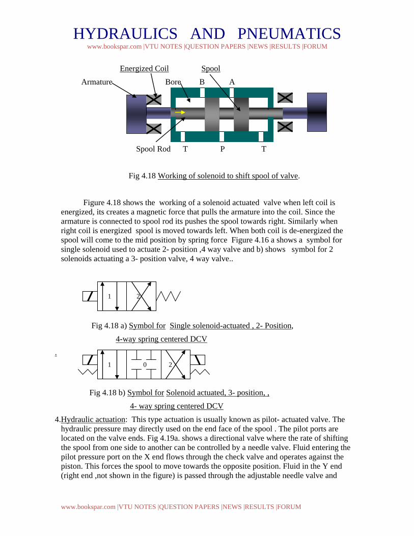
3. Solenoid-actuated DCV : A very common way to actuate a spool valve is by using a solenoid is illustrated in Fig 4.18. When the electric coil (solenoid) is energized, it creates a magnetic force that pulls the armature into the coil. This caused the armature to push on the spool rod to move the spool of the valve.. The advantage of a solenoid lies with in its less switching time.
1 2
1 2
1 2
HYDRAULICS AND PNEUMATICS www.bookspar.com |VTU NOTES |QUESTION PAPERS |NEWS |RESULTS |FORUM
www.bookspar.com |VTU NOTES |QUESTION PAPERS |NEWS |RESULTS |FORUM
Energized Coil Spool
Armature Bore B A
Spool Rod T P T
Fig 4.18 Working of solenoid to shift spool of valve.
Figure 4.18 shows the working of a solenoid actuated valve when left coil is energized, its creates a magnetic force that pulls the armature into the coil. Since the armature is connected to spool rod its pushes the spool towards right. Similarly when right coil is energized spool is moved towards left. When both coil is de-energized the spool will come to the mid position by spring force Figure 4.16 a shows a symbol for single solenoid used to actuate 2- position ,4 way valve and b) shows symbol for 2 solenoids actuating a 3- position valve, 4 way valve..
Fig 4.18 a) Symbol for Single solenoid-actuated , 2- Position,
4-way spring centered DCV
.
Fig 4.18 b) Symbol for Solenoid actuated, 3- position, ,
4- way spring centered DCV
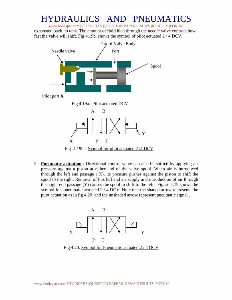
4.Hydraulic actuation: This type actuation is usually known as pilot- actuated valve. The hydraulic pressure may directly used on the end face of the spool . The pilot ports are located on the valve ends. Fig 4.19a. shows a directional valve where the rate of shifting the spool from one side to another can be controlled by a needle valve. Fluid entering the pilot pressure port on the X end flows through the check valve and operates against the piston. This forces the spool to move towards the opposite position. Fluid in the Y end (right end ,not shown in the figure) is passed through the adjustable needle valve and
1 0 2
1 2
HYDRAULICS AND PNEUMATICS www.bookspar.com |VTU NOTES |QUESTION PAPERS |NEWS |RESULTS |FORUM
www.bookspar.com |VTU NOTES |QUESTION PAPERS |NEWS |RESULTS |FORUM
exhausted back to tank. The amount of fluid bled through the needle valve controls how fast the valve will shift. Fig 4.19b. shows the symbol of pilot actuated 2 / 4 DCV.
Part of Valve Body
Needle valve Port
Spool
Pilot port X
Fig 4.19a. Pilot actuated DCV
A B
Y
X P T
Fig 4.19b.. Symbol for pilot actuated 2 /4 DCV
5. Pneumatic actuation : Directional control valve can also be shifted by applying air pressure against a piston at either end of the valve spool. When air is introduced through the left end passage ( X), its pressure pushes against the piston to shift the spool to the right. Removal of this left end air supply and introduction of air through the right end passage (Y) causes the spool to shift to the left. Figure 4.19 shows the symbol for pneumatic actuated 2 / 4 DCV. Note that the shaded arrow represents the pilot actuation as in fig 4.20 and the unshaded arrow represent pneumatic signal .
A B
X Y
P T
Fig 4.20. Symbol for Pneumatic actuated 2 / 4 DCV
HYDRAULICS AND PNEUMATICS www.bookspar.com |VTU NOTES |QUESTION PAPERS |NEWS |RESULTS |FORUM
www.bookspar.com |VTU NOTES |QUESTION PAPERS |NEWS |RESULTS |FORUM
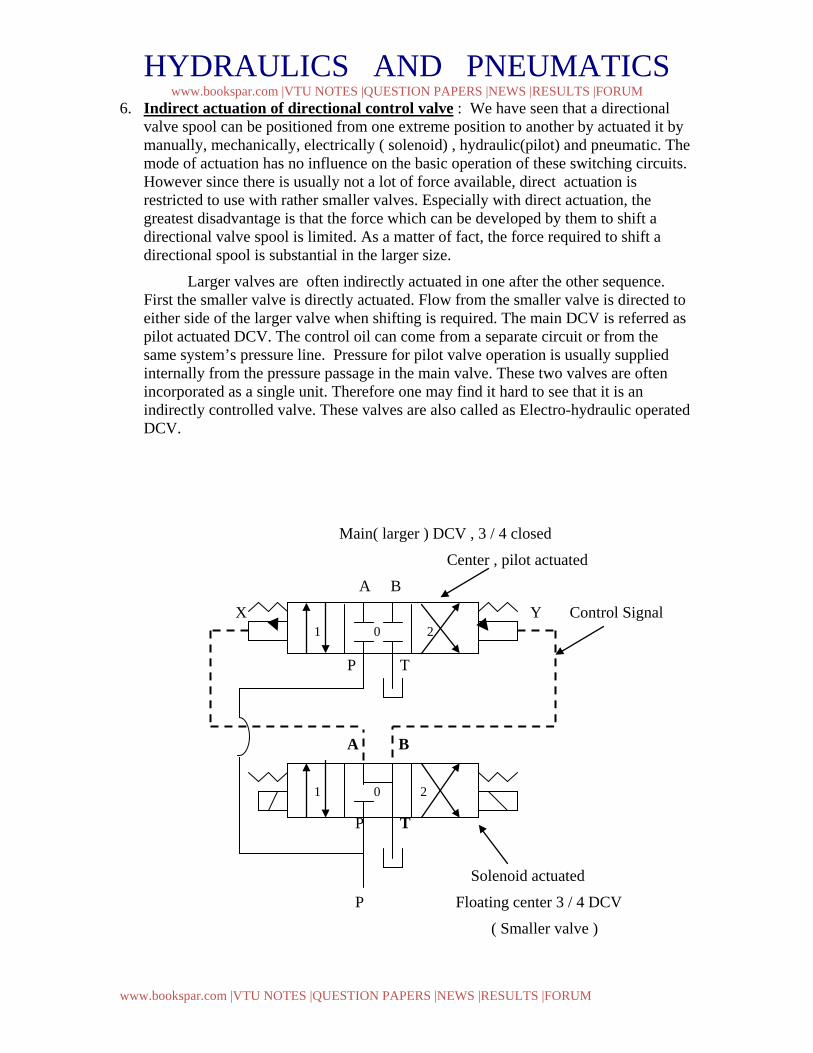
6. Indirect actuation of directional control valve : We have seen that a directional valve spool can be positioned from one extreme position to another by actuated it by manually, mechanically, electrically ( solenoid) , hydraulic(pilot) and pneumatic. The mode of actuation has no influence on the basic operation of these switching circuits. However since there is usually not a lot of force available, direct actuation is restricted to use with rather smaller valves. Especially with direct actuation, the greatest disadvantage is that the force which can be developed by them to shift a directional valve spool is limited. As a matter of fact, the force required to shift a directional spool is substantial in the larger size.
Larger valves are often indirectly actuated in one after the other sequence. First the smaller valve is directly actuated. Flow from the smaller valve is directed to either side of the larger valve when shifting is required. The main DCV is referred as pilot actuated DCV. The control oil can come from a separate circuit or from the same system’s pressure line. Pressure for pilot valve operation is usually supplied internally from the pressure passage in the main valve. These two valves are often incorporated as a single unit. Therefore one may find it hard to see that it is an indirectly controlled valve. These valves are also called as Electro-hydraulic operated DCV.
Main( larger ) DCV , 3 / 4 closed
Center , pilot actuated
A B
X Y Control Signal
P T
A B
P T
Solenoid actuated
P Floating center 3 / 4 DCV
( Smaller valve )
1 0 2
1 0 2
HYDRAULICS AND PNEUMATICS www.bookspar.com |VTU NOTES |QUESTION PAPERS |NEWS |RESULTS |FORUM
www.bookspar.com |VTU NOTES |QUESTION PAPERS |NEWS |RESULTS |FORUM
Fig 4.21a. Symbol for Indirect actuation
For 3 / 4 DCV
A B
P T
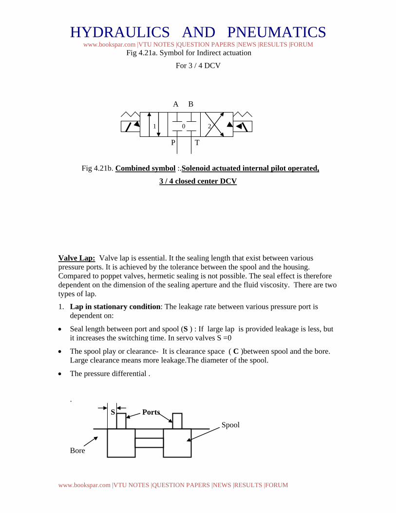
Fig 4.21b. Combined symbol :.Solenoid actuated internal pilot operated,
3 / 4 closed center DCV Valve Lap: Valve lap is essential. It the sealing length that exist between various pressure ports. It is achieved by the tolerance between the spool and the housing. Compared to poppet valves, hermetic sealing is not possible. The seal effect is therefore dependent on the dimension of the sealing aperture and the fluid viscosity. There are two types of lap.
1. Lap in stationary condition: The leakage rate between various pressure port is dependent on:
• Seal length between port and spool (S ) : If large lap is provided leakage is less, but it increases the switching time. In servo valves S =0
• The spool play or clearance- It is clearance space ( C )between spool and the bore. Large clearance means more leakage.The diameter of the spool.
• The pressure differential .
.
S Ports Spool
Bore
1 0 2
HYDRAULICS AND PNEUMATICS www.bookspar.com |VTU NOTES |QUESTION PAPERS |NEWS |RESULTS |FORUM
www.bookspar.com |VTU NOTES |QUESTION PAPERS |NEWS |RESULTS |FORUM
Fig 4.22: Seal Length Between port and spool
Ports Spool
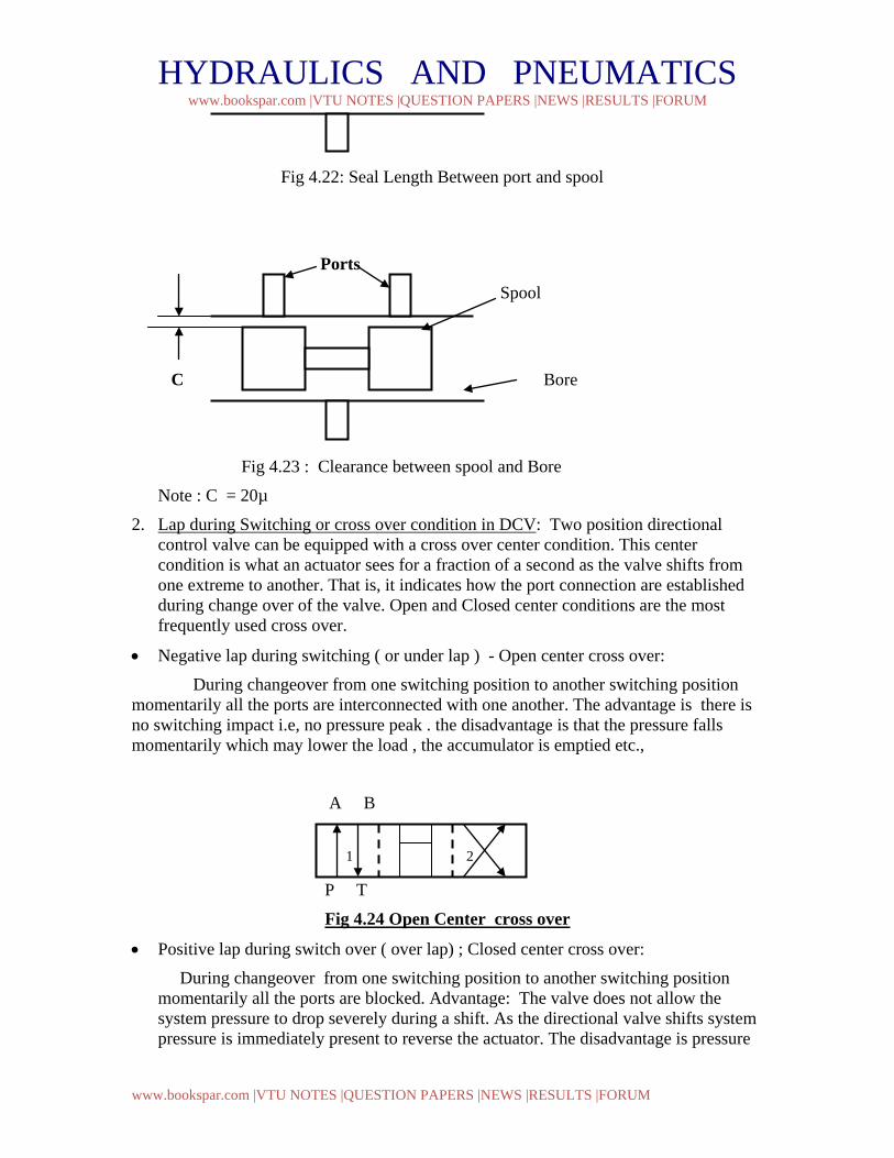
C Bore
Fig 4.23 : Clearance between spool and Bore
Note : C = 20µ
2. Lap during Switching or cross over condition in DCV: Two position directional control valve can be equipped with a cross over center condition. This center condition is what an actuator sees for a fraction of a second as the valve shifts from one extreme to another. That is, it indicates how the port connection are established during change over of the valve. Open and Closed center conditions are the most frequently used cross over.
• Negative lap during switching ( or under lap ) - Open center cross over:
During changeover from one switching position to another switching position momentarily all the ports are interconnected with one another. The advantage is there is no switching impact i.e, no pressure peak . the disadvantage is that the pressure falls momentarily which may lower the load , the accumulator is emptied etc.,
A B
P T
Fig 4.24 Open Center cross over
• Positive lap during switch over ( over lap) ; Closed center cross over:
During changeover from one switching position to another switching position momentarily all the ports are blocked. Advantage: The valve does not allow the system pressure to drop severely during a shift. As the directional valve shifts system pressure is immediately present to reverse the actuator. The disadvantage is pressure
1 2
HYDRAULICS AND PNEUMATICS www.bookspar.com |VTU NOTES |QUESTION PAPERS |NEWS |RESULTS |FORUM
www.bookspar.com |VTU NOTES |QUESTION PAPERS |NEWS |RESULTS |FORUM
peaks momentarily in positive type of valve cross over This type can be lpressure pre- opening and tank pre-opening.
a. Pressure pre- opening: During change over pressure port connection closes last and it opens first in next switching position. It is mostly used for control of hydraulic motors. It provides instant reversing.
A B
P T
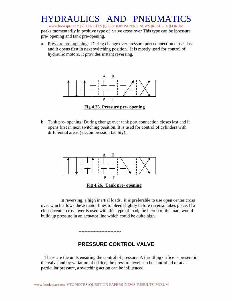
Fig 4.25. Pressure pre- opening
b. Tank pre- opening: During change over tank port connection closes last and it opens first in next switching position. It is used for control of cylinders with differential areas ( decompression facility).
A B
P T
Fig 4.26. Tank pre- opening
In reversing, a high inertial loads, it is preferable to use open center cross over which allows the actuator lines to bleed slightly before reversal takes place. If a closed center cross over is used with this type of load, the inertia of the load, would build up pressure in an actuator line which could be quite high.
----------------------------
PRESSURE CONTROL VALVE
These are the units ensuring the control of pressure. A throttling orifice is present in the valve and by variation of orifice, the pressure level can be controlled or at a particular pressure, a switching action can be influenced.
HYDRAULICS AND PNEUMATICS www.bookspar.com |VTU NOTES |QUESTION PAPERS |NEWS |RESULTS |FORUM
www.bookspar.com |VTU NOTES |QUESTION PAPERS |NEWS |RESULTS |FORUM
Classification: Basically one differentiates between pressure regulating and pressure switching valves. Pressure regulation valves are for maintaining a constant pressure in a system. Pressure switching valves, apart from a definite control function they also perform a switching action. Such valves not only provide a switching signal, as in the case of pressure switches, but also operate themselves as a DCV type of switching within the hydraulic system. In the case of pressure switching valves the piston or spool of the valve remains at a definite position either open or closed depending on the control signal (Yes or No ). The control signal is generally external to the valve. In the case of pressure regulating valves the piston or spool takes up in between position depending on the variable pressure and flow characteristics. As in DCV these valves can also have the valve element either poppet or spool.. With
poppet the sealing is good. But small movement of poppet allows large flows thereby excessive drop
of pressure than required. This results is impact effect.
The spool type of valves allow very fine control or throttling of flows. But of course, the sealing is not very good.
Opening and closing pressure difference:
The minimum pressure at which the valve action starts is called as the opening or cracking pressure. The difference between the cracking pressure (commencement of flow) and the pressure obtained at maximum flow ( normal flow without change of spring force ) is referred as the “opening pressure difference”.
Similarly the difference between the pressure corresponding to nominal flow and no flow during closing of the valve is referred as “closing pressure difference”. This is larger than the opening due to the flow forces acting in the opening direction as also the hysterisis in the spring. Different types of pressure control valves: Pressure control valves are usually named for their primary function such as relief valve, sequence valve, unloading valve, pressure reducing valve and counterbalance valve.
1. Pressure Relief valve:
One of the most important pressure control is the relief valve. Its primary function is to limit the system pressure. Relief valve is found in practically all the Hydraulic system. It is normally a closed valve whose function is to limit the pressure to a specified maximum value by diverting pump flow back to the tank. There are two basic design, a) direct operated or inertia type, b) the pilot operated design ( compound relief valve ). Direct type of relief valve: The direct type of relief valve has two basic working port connection. One port is connected to pump and the other to the tank. The valve consists of a spring chamber ( control chamber ) with an adjustable bias spring which pushes the poppet to its seat, closing the valve. A small opening connecting the tank is provided in the control chamber to drain the oil that may collected due to leakage, thereby preventing the failure of valve. System pressure opposes the poppet, which is
HYDRAULICS AND PNEUMATICS www.bookspar.com |VTU NOTES |QUESTION PAPERS |NEWS |RESULTS |FORUM
www.bookspar.com |VTU NOTES |QUESTION PAPERS |NEWS |RESULTS |FORUM
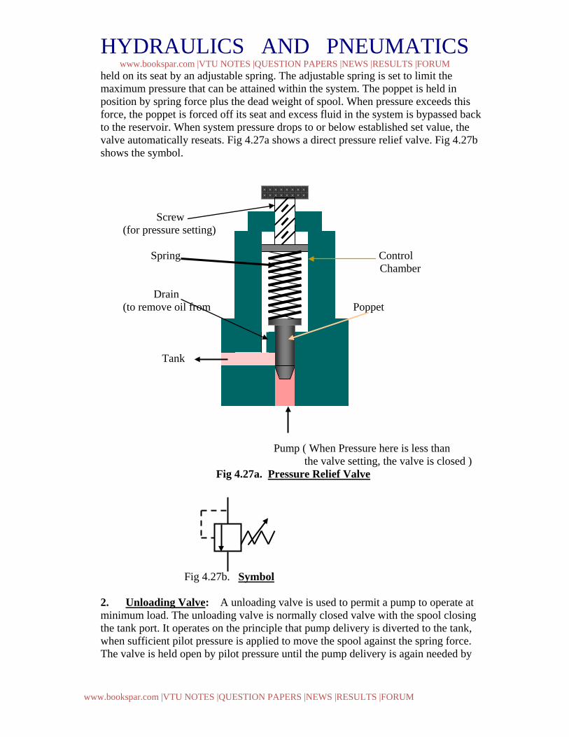
held on its seat by an adjustable spring. The adjustable spring is set to limit the maximum pressure that can be attained within the system. The poppet is held in position by spring force plus the dead weight of spool. When pressure exceeds this force, the poppet is forced off its seat and excess fluid in the system is bypassed back to the reservoir. When system pressure drops to or below established set value, the valve automatically reseats. Fig 4.27a shows a direct pressure relief valve. Fig 4.27b shows the symbol.
Screw (for pressure setting)
Spring Control Chamber Drain (to remove oil from Poppet Tank Pump ( When Pressure here is less than the valve setting, the valve is closed )
Fig 4.27a. Pressure Relief Valve Fig 4.27b. Symbol 2. Unloading Valve: A unloading valve is used to permit a pump to operate at minimum load. The unloading valve is normally closed valve with the spool closing the tank port. It operates on the principle that pump delivery is diverted to the tank, when sufficient pilot pressure is applied to move the spool against the spring force. The valve is held open by pilot pressure until the pump delivery is again needed by
HYDRAULICS AND PNEUMATICS www.bookspar.com |VTU NOTES |QUESTION PAPERS |NEWS |RESULTS |FORUM
www.bookspar.com |VTU NOTES |QUESTION PAPERS |NEWS |RESULTS |FORUM
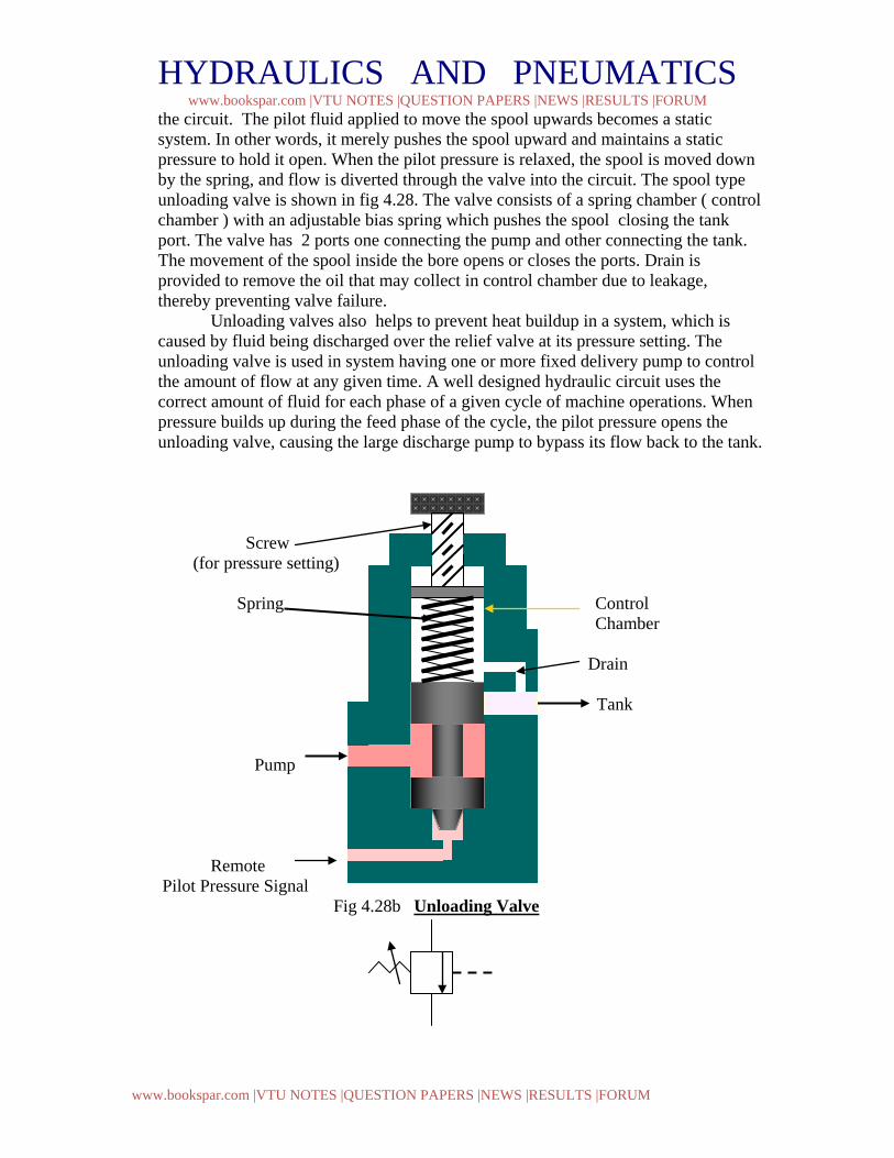
the circuit. The pilot fluid applied to move the spool upwards becomes a static system. In other words, it merely pushes the spool upward and maintains a static pressure to hold it open. When the pilot pressure is relaxed, the spool is moved down by the spring, and flow is diverted through the valve into the circuit. The spool type unloading valve is shown in fig 4.28. The valve consists of a spring chamber ( control chamber ) with an adjustable bias spring which pushes the spool closing the tank port. The valve has 2 ports one connecting the pump and other connecting the tank. The movement of the spool inside the bore opens or closes the ports. Drain is provided to remove the oil that may collect in control chamber due to leakage, thereby preventing valve failure. Unloading valves also helps to prevent heat buildup in a system, which is caused by fluid being discharged over the relief valve at its pressure setting. The unloading valve is used in system having one or more fixed delivery pump to control the amount of flow at any given time. A well designed hydraulic circuit uses the correct amount of fluid for each phase of a given cycle of machine operations. When pressure builds up during the feed phase of the cycle, the pilot pressure opens the unloading valve, causing the large discharge pump to bypass its flow back to the tank. Screw (for pressure setting)
Spring Control
Chamber Drain Tank Pump Remote Pilot Pressure Signal Fig 4.28b Unloading Valve
HYDRAULICS AND PNEUMATICS www.bookspar.com |VTU NOTES |QUESTION PAPERS |NEWS |RESULTS |FORUM
www.bookspar.com |VTU NOTES |QUESTION PAPERS |NEWS |RESULTS |FORUM
Fig 4.28a. Symbol Problem 1. A pressure relief valve has a pressure setting of 69 bars. a) Compute the hydraulic power loss across this valve if it returns all the flow back to the tank from a 0.0013m3/s discharge pump. b) If unloading valve is used to unload the pump and if the pump discharge pressure during unloading equals 1.72 bars, how much power is being wasted ? Solution : b) Pressure setting, p= 69 bars = 69*105 N / m2 ; Discharge, Q = 0.0013m3/ s Power=? We know, Hydraulic Power = p * Q watts Hydraulic power loss = 69 *105 *0.0013 = 8970 watts Ans b) Discharge pressure during unloading , p = 1.72 bars Hydraulic power loss = 1.72*105 * 0.0013 = 223.6 watts Ans One can see that by using unloading valve to unload the pump flow, the power loss is very much less compared to that of relief valve.
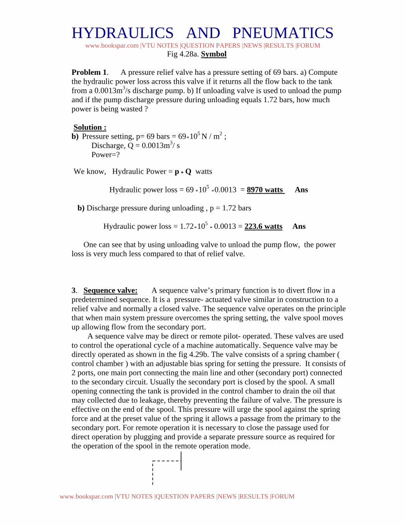
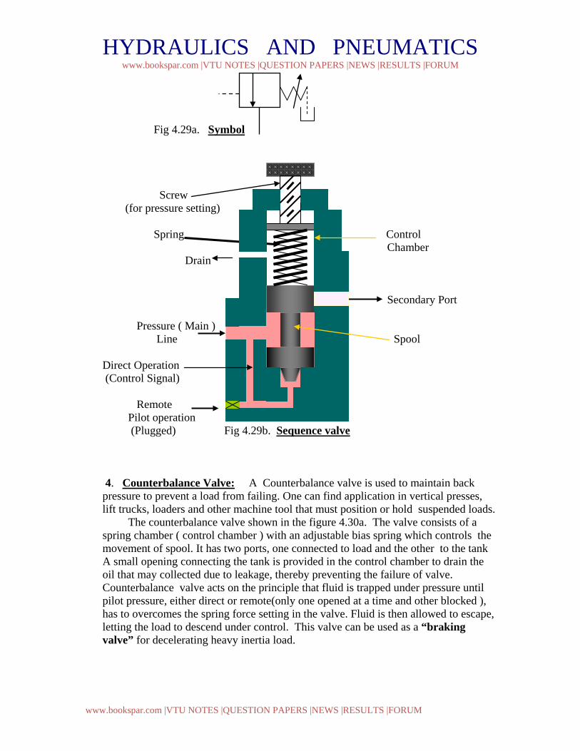
3. Sequence valve: A sequence valve’s primary function is to divert flow in a predetermined sequence. It is a pressure- actuated valve similar in construction to a relief valve and normally a closed valve. The sequence valve operates on the principle that when main system pressure overcomes the spring setting, the valve spool moves up allowing flow from the secondary port. A sequence valve may be direct or remote pilot- operated. These valves are used to control the operational cycle of a machine automatically. Sequence valve may be directly operated as shown in the fig 4.29b. The valve consists of a spring chamber ( control chamber ) with an adjustable bias spring for setting the pressure. It consists of 2 ports, one main port connecting the main line and other (secondary port) connected to the secondary circuit. Usually the secondary port is closed by the spool. A small opening connecting the tank is provided in the control chamber to drain the oil that may collected due to leakage, thereby preventing the failure of valve. The pressure is effective on the end of the spool. This pressure will urge the spool against the spring force and at the preset value of the spring it allows a passage from the primary to the secondary port. For remote operation it is necessary to close the passage used for direct operation by plugging and provide a separate pressure source as required for the operation of the spool in the remote operation mode.
HYDRAULICS AND PNEUMATICS www.bookspar.com |VTU NOTES |QUESTION PAPERS |NEWS |RESULTS |FORUM
www.bookspar.com |VTU NOTES |QUESTION PAPERS |NEWS |RESULTS |FORUM
Fig 4.29a. Symbol Screw (for pressure setting)
Spring Control Chamber Drain Secondary Port Pressure ( Main ) Line Spool Direct Operation (Control Signal) Remote Pilot operation (Plugged) Fig 4.29b. Sequence valve
4. Counterbalance Valve: A Counterbalance valve is used to maintain back pressure to prevent a load from failing. One can find application in vertical presses, lift trucks, loaders and other machine tool that must position or hold suspended loads. The counterbalance valve shown in the figure 4.30a. The valve consists of a spring chamber ( control chamber ) with an adjustable bias spring which controls the movement of spool. It has two ports, one connected to load and the other to the tank A small opening connecting the tank is provided in the control chamber to drain the oil that may collected due to leakage, thereby preventing the failure of valve. Counterbalance valve acts on the principle that fluid is trapped under pressure until pilot pressure, either direct or remote(only one opened at a time and other blocked ), has to overcomes the spring force setting in the valve. Fluid is then allowed to escape, letting the load to descend under control. This valve can be used as a “braking valve” for decelerating heavy inertia load.
HYDRAULICS AND PNEUMATICS www.bookspar.com |VTU NOTES |QUESTION PAPERS |NEWS |RESULTS |FORUM
www.bookspar.com |VTU NOTES |QUESTION PAPERS |NEWS |RESULTS |FORUM
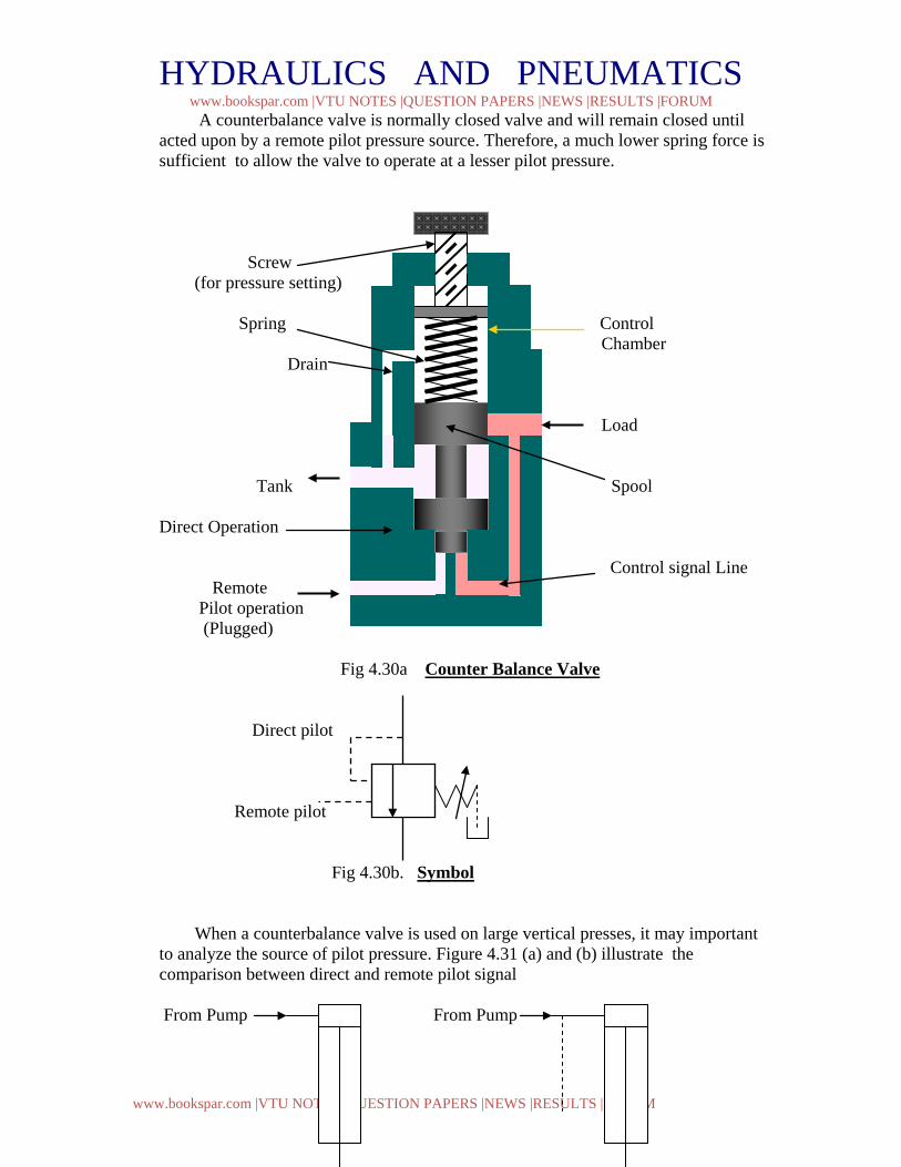
A counterbalance valve is normally closed valve and will remain closed until acted upon by a remote pilot pressure source. Therefore, a much lower spring force is sufficient to allow the valve to operate at a lesser pilot pressure. Screw (for pressure setting)
Spring Control Chamber Drain Load Tank Spool Direct Operation Control signal Line Remote Pilot operation (Plugged)
Fig 4.30a Counter Balance Valve Direct pilot Remote pilot Fig 4.30b. Symbol
When a counterbalance valve is used on large vertical presses, it may important to analyze the source of pilot pressure. Figure 4.31 (a) and (b) illustrate the comparison between direct and remote pilot signal From Pump From Pump

HYDRAULICS AND PNEUMATICS www.bookspar.com |VTU NOTES |QUESTION PAPERS |NEWS |RESULTS |FORUM
www.bookspar.com |VTU NOTES |QUESTION PAPERS |NEWS |RESULTS |FORUM
To Tank To Tank 200bar + 100 kN 100 kN Fig 4.31a Direct Pilot Fig 4.31b. Remote pilot Let Piston area, AP = 100 cm2 =0.01 m2
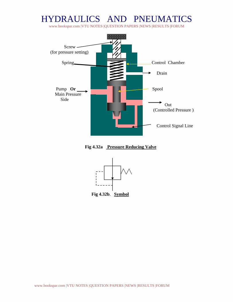
Ring area, AR = 50 cm2 = 0.005m2 Load , F = 100 kN = 100000 N The pressure to support the load is therefore equal to , p = F / AR = 100000 / 0.005 = 20*106 N / m2 = 200 bar Hence a pressure of 200 bar is needed to support the load. If pilot pressure is taken directly as shown in fig 4.31a, then the counterbalance valve should open at about 200 bar or slightly higher because of inertia and friction. Hence the spring setting is about 200 bar or slightly higher. In other case ( fig 4.31b) if remote pilot pressure is taken from the pressure line at the top of the cylinder, a choice of the operating pressure can be made for the valve. Since the valve is normally closed valve and will remain closed until acted upon by a remote pilot pressure source. Therefore, a much lower spring force can be selected to allow the valve to operate at a lesser pilot pressure. 5. Pressure Reducing Valve: Pressure reducing valve is used to limit its outlet pressure. Reducing valves are used for the operation of branch circuits, where pressure may vary from the main system pressures. The pressure reducing valve is normally an open type valve. Figure 4.32 shows the pressure reducing valve. The valve consists of a spring chamber ( control chamber ) with an adjustable spring to set the pressure as required by the system. A small opening is provided in the control chamber to drain the oil that may be collected due to leakage, thereby preventing the failure of valve. A free flow passage is provided through the valve from inlet to secondary outlet until a signal from the outlet side tends to throttle the passage through the valve. The valve operates on the principle that pilot pressure from the controlled pressure side opposes an adjustable bias spring normally holding the valve open. When the two forces are equal, the pressure downstream is controlled at the pressure setting. Thus, it can be visualized that if the spring has greater force, the valves open wider and if the controlled pressure has greater force, the valves moves towards the spring and throttles the flow.
HYDRAULICS AND PNEUMATICS www.bookspar.com |VTU NOTES |QUESTION PAPERS |NEWS |RESULTS |FORUM
www.bookspar.com |VTU NOTES |QUESTION PAPERS |NEWS |RESULTS |FORUM
Screw (for pressure setting)
Spring Control Chamber Drain Pump Or Spool Main Pressure Side Out (Controlled Pressure ) Control Signal Line
Fig 4.32a Pressure Reducing Valve
Fig 4.32b. Symbol
HYDRAULICS AND PNEUMATICS www.bookspar.com |VTU NOTES |QUESTION PAPERS |NEWS |RESULTS |FORUM
www.bookspar.com |VTU NOTES |QUESTION PAPERS |NEWS |RESULTS |FORUM
CHAPTER 5. HYDRAULIC CIRCUIT DESIGN AND ANALYSIS
A Hydraulic circuit is a group of components such as pumps, actuators, and control valves so arranged that they will perform a useful task. When analyzing or designing a hydraulic circuit, the following three important considerations must be taken into account:
1. Safety of operation
2. Performance of desired function
3. Efficiency of operation
It is very important for the fluid power ( Hydraulics and Pneumatics ) designer to have a working knowledge of components and how they operate in a circuit. Hydraulic circuits are developed through the use of graphical symbols for all components. The symbols have to conform to the ANSI specification.
5.1 Control of a Single- Acting Hydraulic Cylinder :
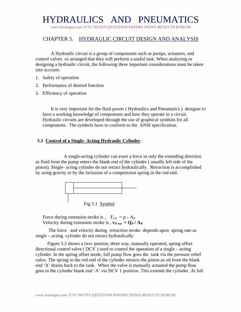
A single-acting cylinder can exert a force in only the extending direction as fluid from the pump enters the blank end of the cylinder ( usually left side of the piston). Single- acting cylinder do not retract hydraulically. Retraction is accomplished by using gravity or by the inclusion of a compression spring in the rod end.
A
Fig 5.1 Symbol
Force during extension stroke is , Fext = p * AP Velocity during extension stroke is , vP ext = QP / AP
The force and velocity during retraction stroke depends upon spring rate as single – acting cylinder do not retract hydraulically
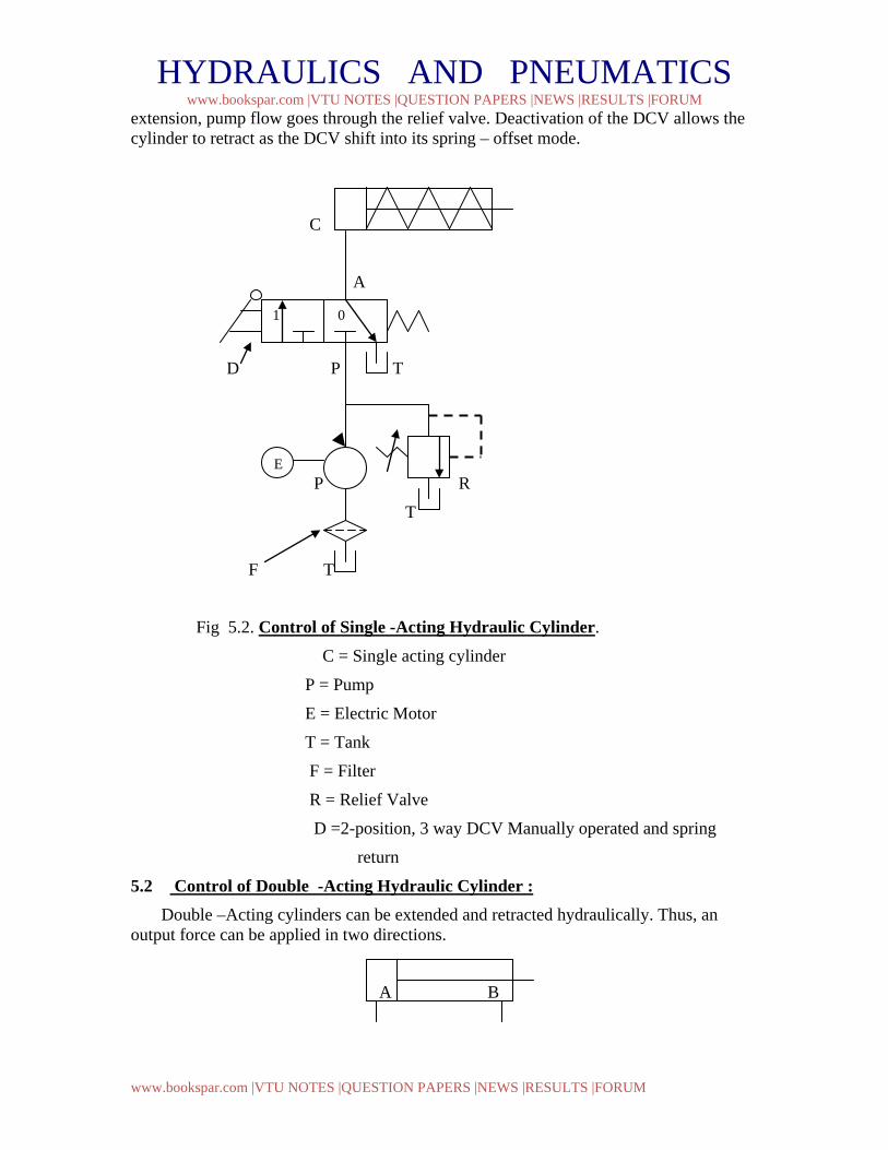
Figure 5.2 shows a two- postion, three way, manually operated, spring offset directional control valve ( DCV ) used to control the operation of a single – acting cylinder. In the spring offset mode, full pump flow goes the tank via the pressure relief valve. The spring in the rod end of the cylinder retracts the piston as oil from the blank end ‘A’ drains back to the rank. When the valve is manually actuated the pump flow goes to the cylinder blank end ‘A’ via DCV 1 position. This extends the cylinder. At full
HYDRAULICS AND PNEUMATICS www.bookspar.com |VTU NOTES |QUESTION PAPERS |NEWS |RESULTS |FORUM
www.bookspar.com |VTU NOTES |QUESTION PAPERS |NEWS |RESULTS |FORUM
extension, pump flow goes through the relief valve. Deactivation of the DCV allows the cylinder to retract as the DCV shift into its spring – offset mode.
C
A
D P T
P R
T
F T
Fig 5.2. Control of Single -Acting Hydraulic Cylinder.
C = Single acting cylinder
P = Pump
E = Electric Motor
T = Tank
F = Filter
R = Relief Valve
D =2-position, 3 way DCV Manually operated and spring
return
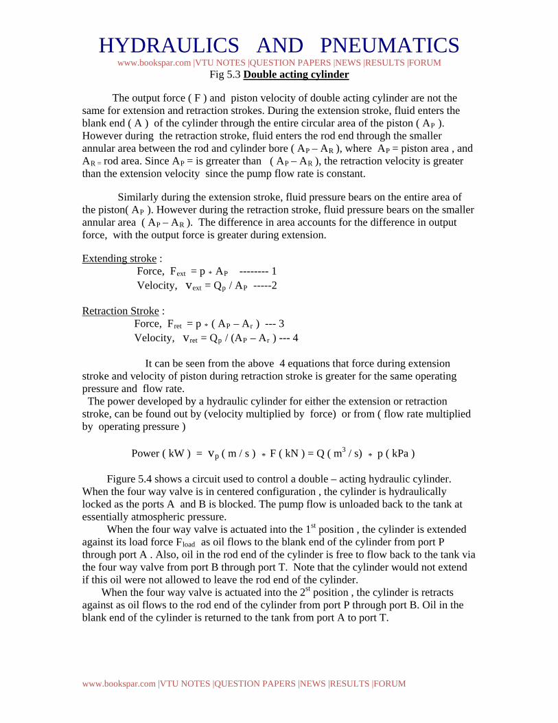
5.2 Control of Double -Acting Hydraulic Cylinder : Double –Acting cylinders can be extended and retracted hydraulically. Thus, an output force can be applied in two directions.
A B
1 0
E
HYDRAULICS AND PNEUMATICS www.bookspar.com |VTU NOTES |QUESTION PAPERS |NEWS |RESULTS |FORUM
www.bookspar.com |VTU NOTES |QUESTION PAPERS |NEWS |RESULTS |FORUM
Fig 5.3 Double acting cylinder
The output force ( F ) and piston velocity of double acting cylinder are not the same for extension and retraction strokes. During the extension stroke, fluid enters the blank end ( A ) of the cylinder through the entire circular area of the piston ( AP ). However during the retraction stroke, fluid enters the rod end through the smaller annular area between the rod and cylinder bore ( AP – AR ), where AP = piston area , and AR = rod area. Since AP = is grreater than ( AP – AR ), the retraction velocity is greater than the extension velocity since the pump flow rate is constant.
Similarly during the extension stroke, fluid pressure bears on the entire area of the piston( AP ). However during the retraction stroke, fluid pressure bears on the smaller annular area ( AP – AR ). The difference in area accounts for the difference in output force, with the output force is greater during extension.
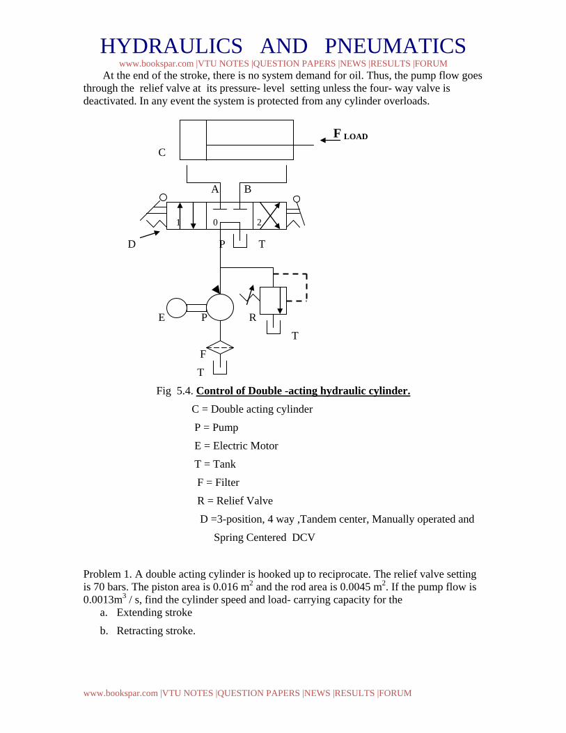
Extending stroke : Force, Fext = p * AP -------- 1 Velocity, vext = Qp / AP -----2 Retraction Stroke : Force, Fret = p * ( AP – Ar ) --- 3 Velocity, vret = Qp / (AP – Ar ) --- 4 It can be seen from the above 4 equations that force during extension stroke and velocity of piston during retraction stroke is greater for the same operating pressure and flow rate. The power developed by a hydraulic cylinder for either the extension or retraction stroke, can be found out by (velocity multiplied by force) or from ( flow rate multiplied by operating pressure ) Power ( kW ) = vp ( m / s ) * F ( kN ) = Q ( m3 / s) * p ( kPa ) Figure 5.4 shows a circuit used to control a double – acting hydraulic cylinder. When the four way valve is in centered configuration , the cylinder is hydraulically locked as the ports A and B is blocked. The pump flow is unloaded back to the tank at essentially atmospheric pressure. When the four way valve is actuated into the 1st position , the cylinder is extended against its load force Fload as oil flows to the blank end of the cylinder from port P through port A . Also, oil in the rod end of the cylinder is free to flow back to the tank via the four way valve from port B through port T. Note that the cylinder would not extend if this oil were not allowed to leave the rod end of the cylinder. When the four way valve is actuated into the 2st position , the cylinder is retracts against as oil flows to the rod end of the cylinder from port P through port B. Oil in the blank end of the cylinder is returned to the tank from port A to port T.
HYDRAULICS AND PNEUMATICS www.bookspar.com |VTU NOTES |QUESTION PAPERS |NEWS |RESULTS |FORUM
www.bookspar.com |VTU NOTES |QUESTION PAPERS |NEWS |RESULTS |FORUM
At the end of the stroke, there is no system demand for oil. Thus, the pump flow goes through the relief valve at its pressure- level setting unless the four- way valve is deactivated. In any event the system is protected from any cylinder overloads.
F LOAD
C
A B
D P T
E P R
T
F
T
Fig 5.4. Control of Double -acting hydraulic cylinder. C = Double acting cylinder
P = Pump
E = Electric Motor
T = Tank
F = Filter
R = Relief Valve
D =3-position, 4 way ,Tandem center, Manually operated and
Spring Centered DCV
Problem 1. A double acting cylinder is hooked up to reciprocate. The relief valve setting is 70 bars. The piston area is 0.016 m2 and the rod area is 0.0045 m2. If the pump flow is 0.0013m3 / s, find the cylinder speed and load- carrying capacity for the
a. Extending stroke
b. Retracting stroke.
1 0 2
HYDRAULICS AND PNEUMATICS www.bookspar.com |VTU NOTES |QUESTION PAPERS |NEWS |RESULTS |FORUM
www.bookspar.com |VTU NOTES |QUESTION PAPERS |NEWS |RESULTS |FORUM
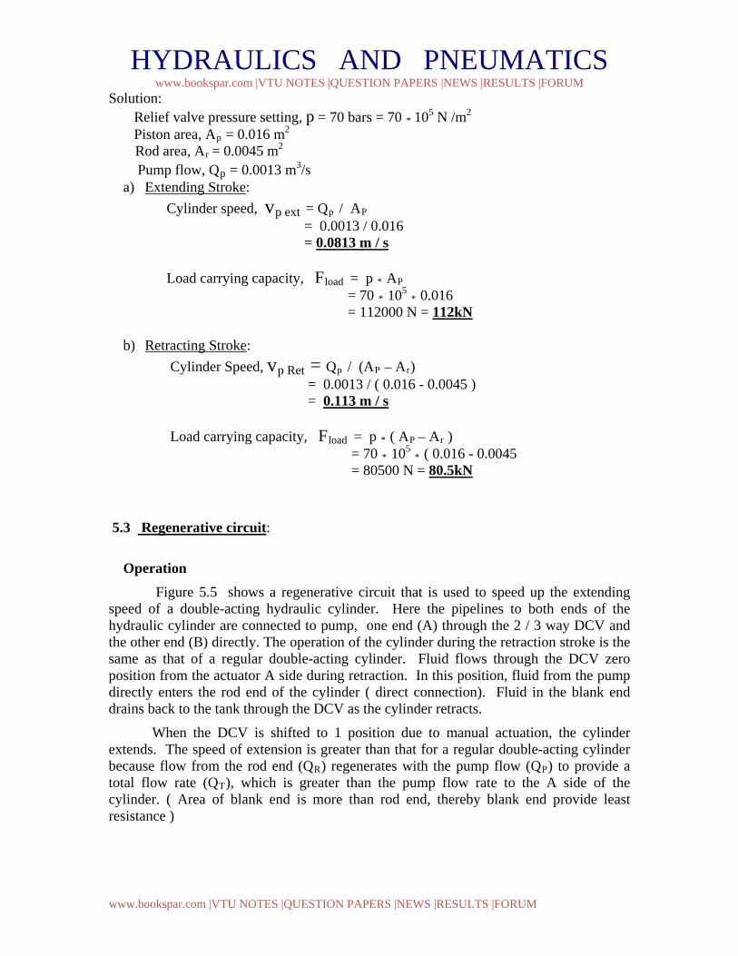
Solution: Relief valve pressure setting, p = 70 bars = 70 * 105 N /m2 Piston area, Ap = 0.016 m2
Rod area, Ar = 0.0045 m2 Pump flow, Qp = 0.0013 m3/s
a) Extending Stroke: Cylinder speed, vp ext = Qp / AP = 0.0013 / 0.016 = 0.0813 m / s Load carrying capacity, Fload = p * AP = 70 * 105 * 0.016 = 112000 N = 112kN
b) Retracting Stroke: Cylinder Speed, vp Ret = Qp / (AP – Ar) = 0.0013 / ( 0.016 - 0.0045 ) = 0.113 m / s Load carrying capacity, Fload = p * ( AP – Ar ) = 70 * 105 * ( 0.016 - 0.0045 = 80500 N = 80.5kN 5.3 Regenerative circuit:
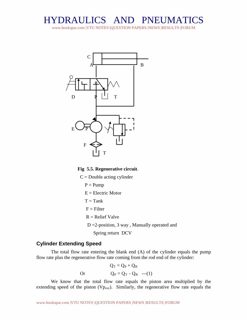
Operation Figure 5.5 shows a regenerative circuit that is used to speed up the extending speed of a double-acting hydraulic cylinder. Here the pipelines to both ends of the hydraulic cylinder are connected to pump, one end (A) through the 2 / 3 way DCV and the other end (B) directly. The operation of the cylinder during the retraction stroke is the same as that of a regular double-acting cylinder. Fluid flows through the DCV zero position from the actuator A side during retraction. In this position, fluid from the pump directly enters the rod end of the cylinder ( direct connection). Fluid in the blank end drains back to the tank through the DCV as the cylinder retracts.
When the DCV is shifted to 1 position due to manual actuation, the cylinder extends. The speed of extension is greater than that for a regular double-acting cylinder because flow from the rod end (QR) regenerates with the pump flow (QP) to provide a total flow rate (QT), which is greater than the pump flow rate to the A side of the cylinder. ( Area of blank end is more than rod end, thereby blank end provide least resistance )
HYDRAULICS AND PNEUMATICS www.bookspar.com |VTU NOTES |QUESTION PAPERS |NEWS |RESULTS |FORUM
www.bookspar.com |VTU NOTES |QUESTION PAPERS |NEWS |RESULTS |FORUM
C
A B
D P T
E P
F
T
Fig 5.5. Regenerative circuit. C = Double acting cylinder
P = Pump
E = Electric Motor
T = Tank
F = Filter
R = Relief Valve
D =2-position, 3 way , Manually operated and
Spring return DCV
Cylinder Extending Speed The total flow rate entering the blank end (A) of the cylinder equals the pump flow rate plus the regenerative flow rate coming from the rod end of the cylinder:
QT = QP + QR
Or QP = QT - QR ---(1)
We know that the total flow rate equals the piston area multiplied by the extending speed of the piston (Vpext). Similarly, the regenerative flow rate equals the
1 0
HYDRAULICS AND PNEUMATICS www.bookspar.com |VTU NOTES |QUESTION PAPERS |NEWS |RESULTS |FORUM
www.bookspar.com |VTU NOTES |QUESTION PAPERS |NEWS |RESULTS |FORUM
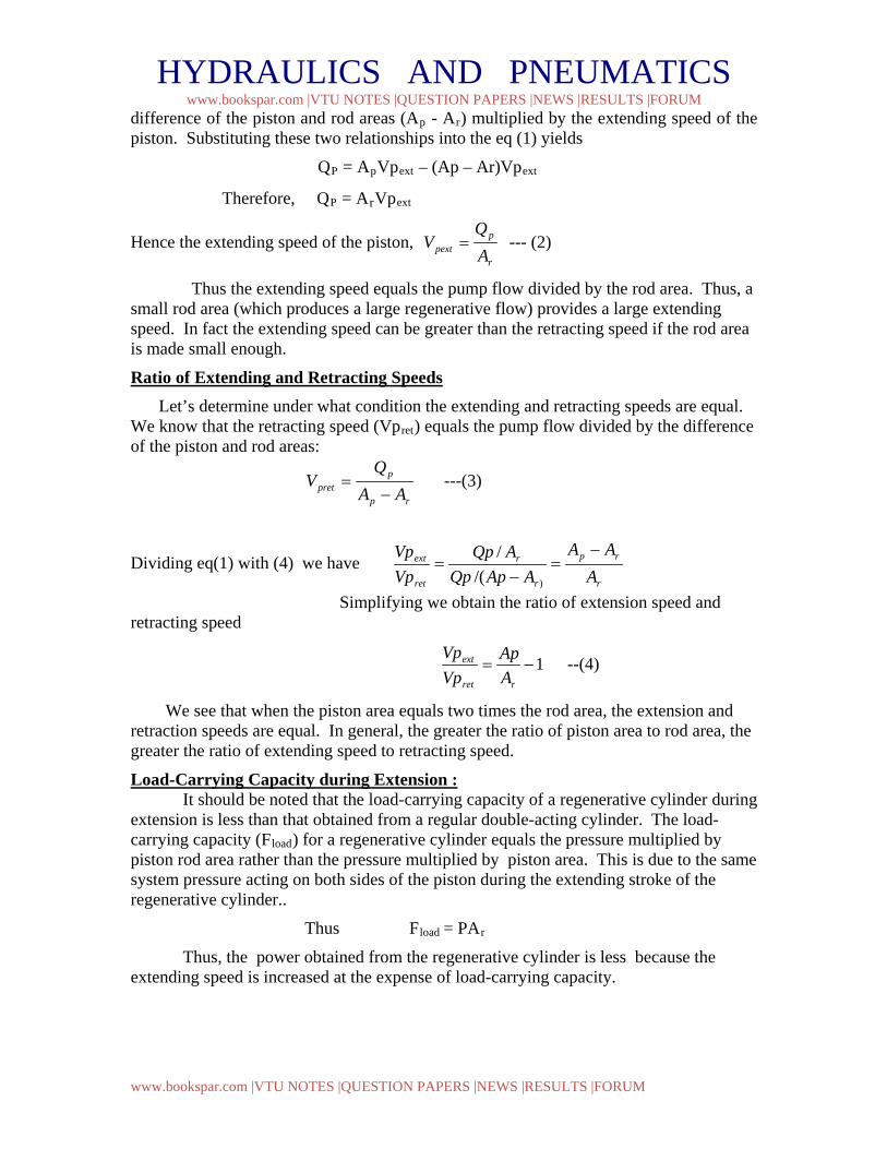
difference of the piston and rod areas (Ap - Ar) multiplied by the extending speed of the piston. Substituting these two relationships into the eq (1) yields
QP = ApVpext – (Ap – Ar)Vpext
Therefore, QP = ArVpext
Hence the extending speed of the piston, r
ppext A
QV = --- (2)
Thus the extending speed equals the pump flow divided by the rod area. Thus, a small rod area (which produces a large regenerative flow) provides a large extending speed. In fact the extending speed can be greater than the retracting speed if the rod area is made small enough.
Ratio of Extending and Retracting Speeds Let’s determine under what condition the extending and retracting speeds are equal. We know that the retracting speed (Vpret) equals the pump flow divided by the difference of the piston and rod areas:
rp
ppret AA
QV
−= ---(3)
Dividing eq(1) with (4) we have r
rp
r
r
ret
ext
AAA
AApQpAQp
VpVp −
=−
=)/(
/
Simplifying we obtain the ratio of extension speed and retracting speed
1−=rret
ext
AAp
VpVp
--(4)
We see that when the piston area equals two times the rod area, the extension and retraction speeds are equal. In general, the greater the ratio of piston area to rod area, the greater the ratio of extending speed to retracting speed.
Load-Carrying Capacity during Extension : It should be noted that the load-carrying capacity of a regenerative cylinder during extension is less than that obtained from a regular double-acting cylinder. The load-carrying capacity (Fload) for a regenerative cylinder equals the pressure multiplied by piston rod area rather than the pressure multiplied by piston area. This is due to the same system pressure acting on both sides of the piston during the extending stroke of the regenerative cylinder..
Thus Fload = PAr
Thus, the power obtained from the regenerative cylinder is less because the extending speed is increased at the expense of load-carrying capacity.
HYDRAULICS AND PNEUMATICS www.bookspar.com |VTU NOTES |QUESTION PAPERS |NEWS |RESULTS |FORUM
www.bookspar.com |VTU NOTES |QUESTION PAPERS |NEWS |RESULTS |FORUM
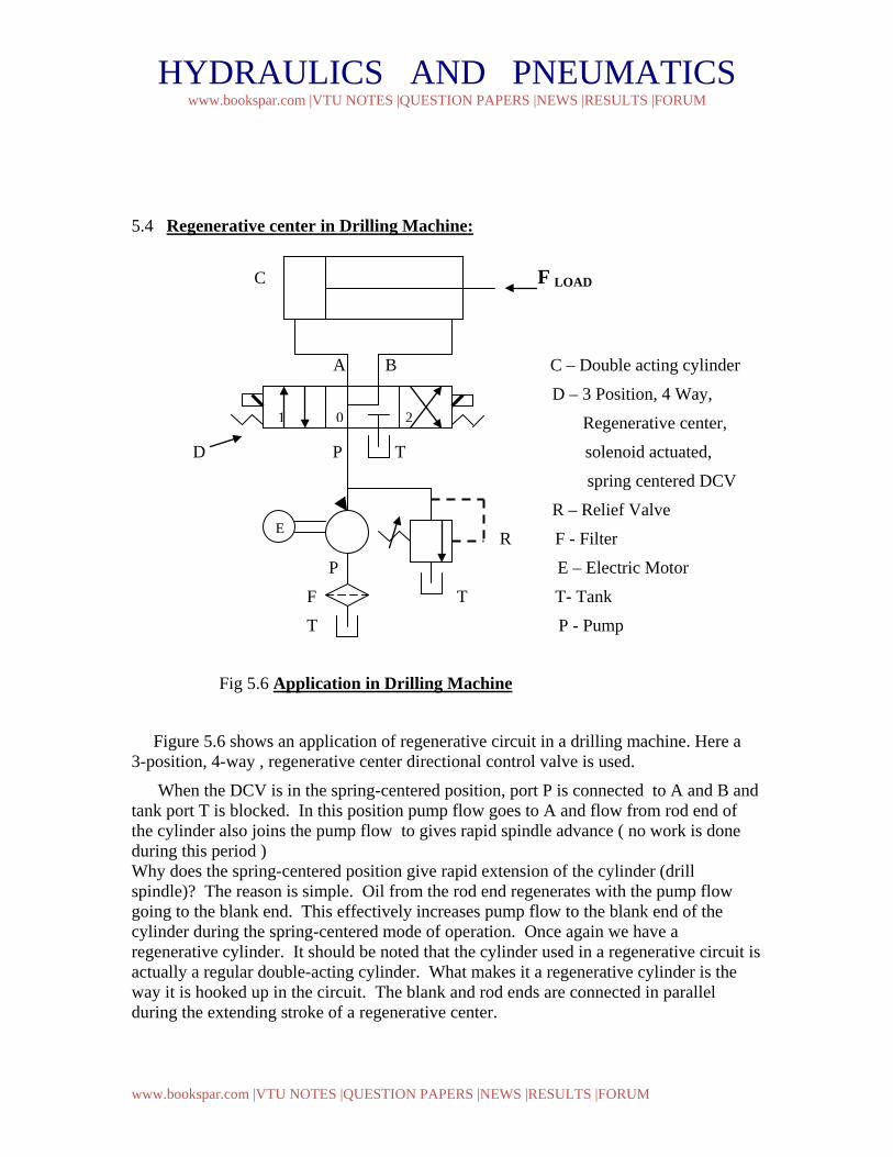
5.4 Regenerative center in Drilling Machine:
C F LOAD
A B C – Double acting cylinder
D – 3 Position, 4 Way,
Regenerative center,
D P T solenoid actuated,
spring centered DCV
R – Relief Valve
R F - Filter
P E – Electric Motor
F T T- Tank
T P - Pump
Fig 5.6 Application in Drilling Machine
Figure 5.6 shows an application of regenerative circuit in a drilling machine. Here a 3-position, 4-way , regenerative center directional control valve is used.
When the DCV is in the spring-centered position, port P is connected to A and B and tank port T is blocked. In this position pump flow goes to A and flow from rod end of the cylinder also joins the pump flow to gives rapid spindle advance ( no work is done during this period ) Why does the spring-centered position give rapid extension of the cylinder (drill spindle)? The reason is simple. Oil from the rod end regenerates with the pump flow going to the blank end. This effectively increases pump flow to the blank end of the cylinder during the spring-centered mode of operation. Once again we have a regenerative cylinder. It should be noted that the cylinder used in a regenerative circuit is actually a regular double-acting cylinder. What makes it a regenerative cylinder is the way it is hooked up in the circuit. The blank and rod ends are connected in parallel during the extending stroke of a regenerative center.
1 0 2
E
HYDRAULICS AND PNEUMATICS www.bookspar.com |VTU NOTES |QUESTION PAPERS |NEWS |RESULTS |FORUM
www.bookspar.com |VTU NOTES |QUESTION PAPERS |NEWS |RESULTS |FORUM
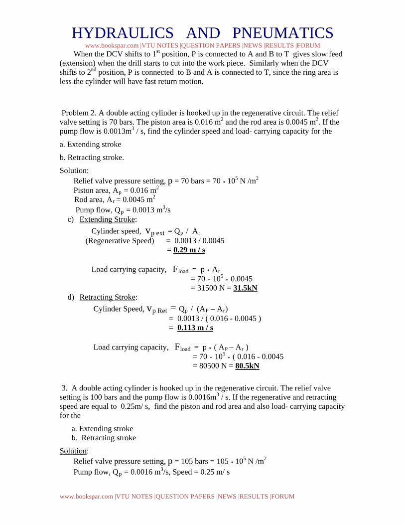
When the DCV shifts to 1st position, P is connected to A and B to T gives slow feed (extension) when the drill starts to cut into the work piece. Similarly when the DCV shifts to 2nd position, P is connected to B and A is connected to T, since the ring area is less the cylinder will have fast return motion.
Problem 2. A double acting cylinder is hooked up in the regenerative circuit. The relief valve setting is 70 bars. The piston area is 0.016 m2 and the rod area is 0.0045 m2. If the pump flow is 0.0013m3 / s, find the cylinder speed and load- carrying capacity for the
a. Extending stroke
b. Retracting stroke.
Solution: Relief valve pressure setting, p = 70 bars = 70 * 105 N /m2 Piston area, Ap = 0.016 m2
Rod area, Ar = 0.0045 m2 Pump flow, Qp = 0.0013 m3/s
c) Extending Stroke: Cylinder speed, vp ext = Qp / Ar (Regenerative Speed) = 0.0013 / 0.0045 = 0.29 m / s Load carrying capacity, Fload = p * Ar = 70 * 105 * 0.0045 = 31500 N = 31.5kN
d) Retracting Stroke: Cylinder Speed, vp Ret = Qp / (AP – Ar) = 0.0013 / ( 0.016 - 0.0045 ) = 0.113 m / s Load carrying capacity, Fload = p * ( AP – Ar ) = 70 * 105 * ( 0.016 - 0.0045 = 80500 N = 80.5kN
3. A double acting cylinder is hooked up in the regenerative circuit. The relief valve setting is 100 bars and the pump flow is 0.0016m3 / s. If the regenerative and retracting speed are equal to 0.25m/ s, find the piston and rod area and also load- carrying capacity for the
a. Extending stroke b. Retracting stroke
Solution: Relief valve pressure setting, p = 105 bars = 105 * 105 N /m2 Pump flow, Qp = 0.0016 m3/s, Speed = 0.25 m/ s
HYDRAULICS AND PNEUMATICS www.bookspar.com |VTU NOTES |QUESTION PAPERS |NEWS |RESULTS |FORUM
www.bookspar.com |VTU NOTES |QUESTION PAPERS |NEWS |RESULTS |FORUM
We have regenerative cylinder speed, vp ext = Qp / Ar Therefore Rod area, Ar = Qp / vp ext = 0.0016 / 0.25 = 0.0064m2 • Piston Area, AP = 2 Ar = 2* 0.0064 = 0.0128 m2
a) Extending Stroke:
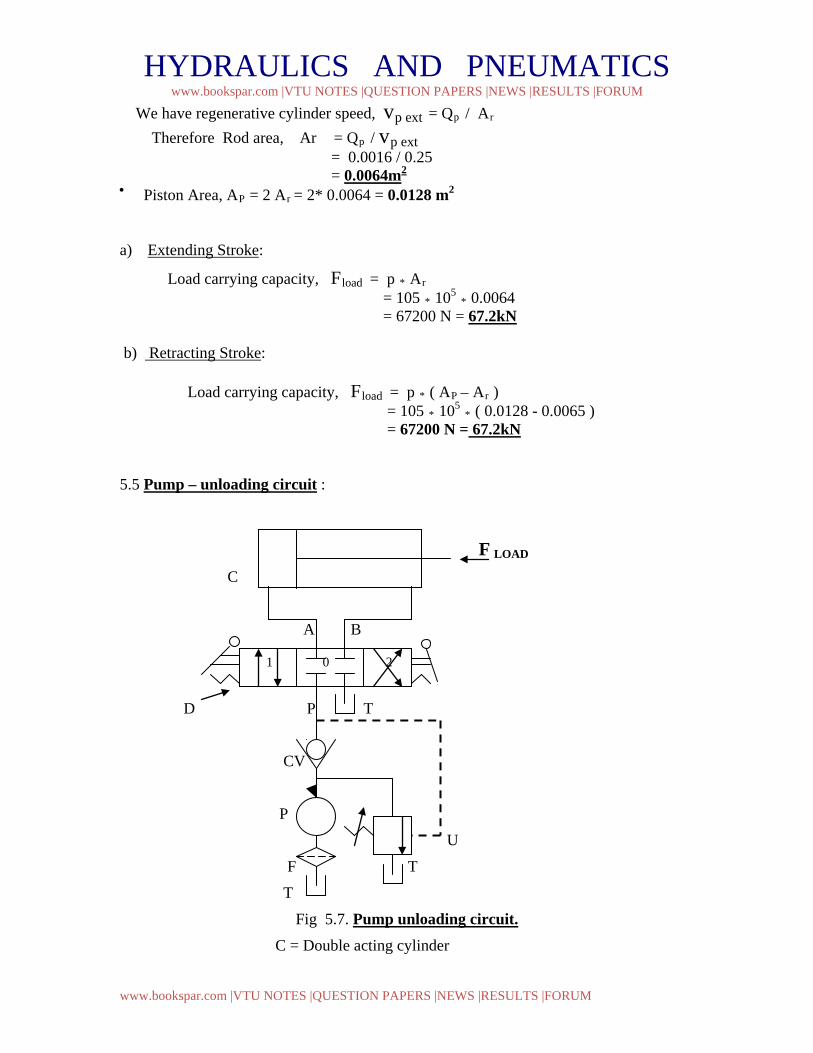
Load carrying capacity, Fload = p * Ar = 105 * 105 * 0.0064 = 67200 N = 67.2kN b) Retracting Stroke: Load carrying capacity, Fload = p * ( AP – Ar ) = 105 * 105 * ( 0.0128 - 0.0065 ) = 67200 N = 67.2kN 5.5 Pump – unloading circuit :
F LOAD
C
A B
D P T
CV
P
U
F T
T
Fig 5.7. Pump unloading circuit. C = Double acting cylinder
1 0 2
HYDRAULICS AND PNEUMATICS www.bookspar.com |VTU NOTES |QUESTION PAPERS |NEWS |RESULTS |FORUM
www.bookspar.com |VTU NOTES |QUESTION PAPERS |NEWS |RESULTS |FORUM
P = Pump
T = Tank
F = Filter
U = unloadingValve
D =3-position, 4 way ,closed center, Manually operated and
Spring Centered DCV
In Fig. 5.7 we see a circuit using an unloading valve to unload a pump. The unloading valve opens when the cylinder reaches the end of its extension stroke because the check valve keeps high-pressure oil in the pilot line of the unloading valve. When the DCV is shifted to retract the cylinder, the motion of the piston reduces the pressure in the pilot line of the unloading valve. This resets the unloading valve until the cylinder is fully retracted, at which point the unloading valve unloads the pump. Thus, the unloading valve unloads the pump at the ends of the extending and retraction strokes as well as in the spring-centered position of the DCV.
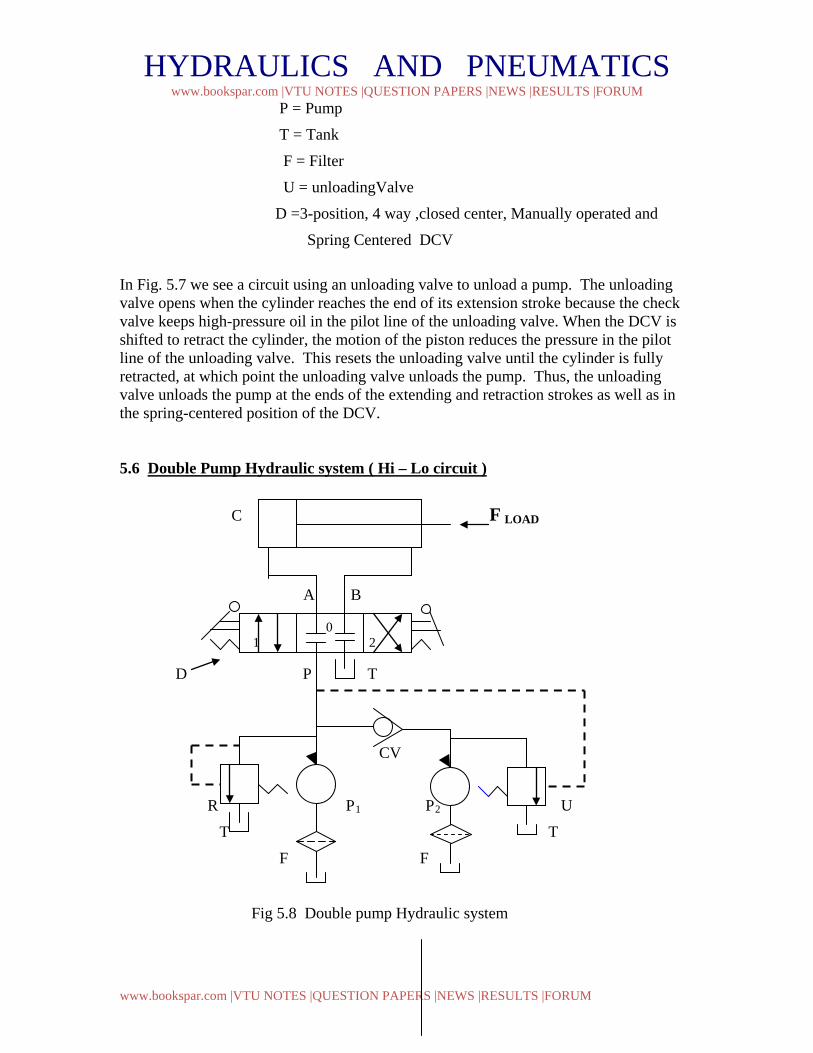
5.6 Double Pump Hydraulic system ( Hi – Lo circuit )
C F LOAD
A B
D P T
CV
R P1 P2 U
T T
F F
Fig 5.8 Double pump Hydraulic system
0 1 2
HYDRAULICS AND PNEUMATICS www.bookspar.com |VTU NOTES |QUESTION PAPERS |NEWS |RESULTS |FORUM
www.bookspar.com |VTU NOTES |QUESTION PAPERS |NEWS |RESULTS |FORUM
P1 -- Low discharge, High pressure pump CV – Check valve P2 -- High discharge, Low pressure pump D – 3 Position, 4 Way, closed R -- Relief valve center, manual actuated DCV U – Unloading valve C- Double acting cylinder T - Tank F - Filter
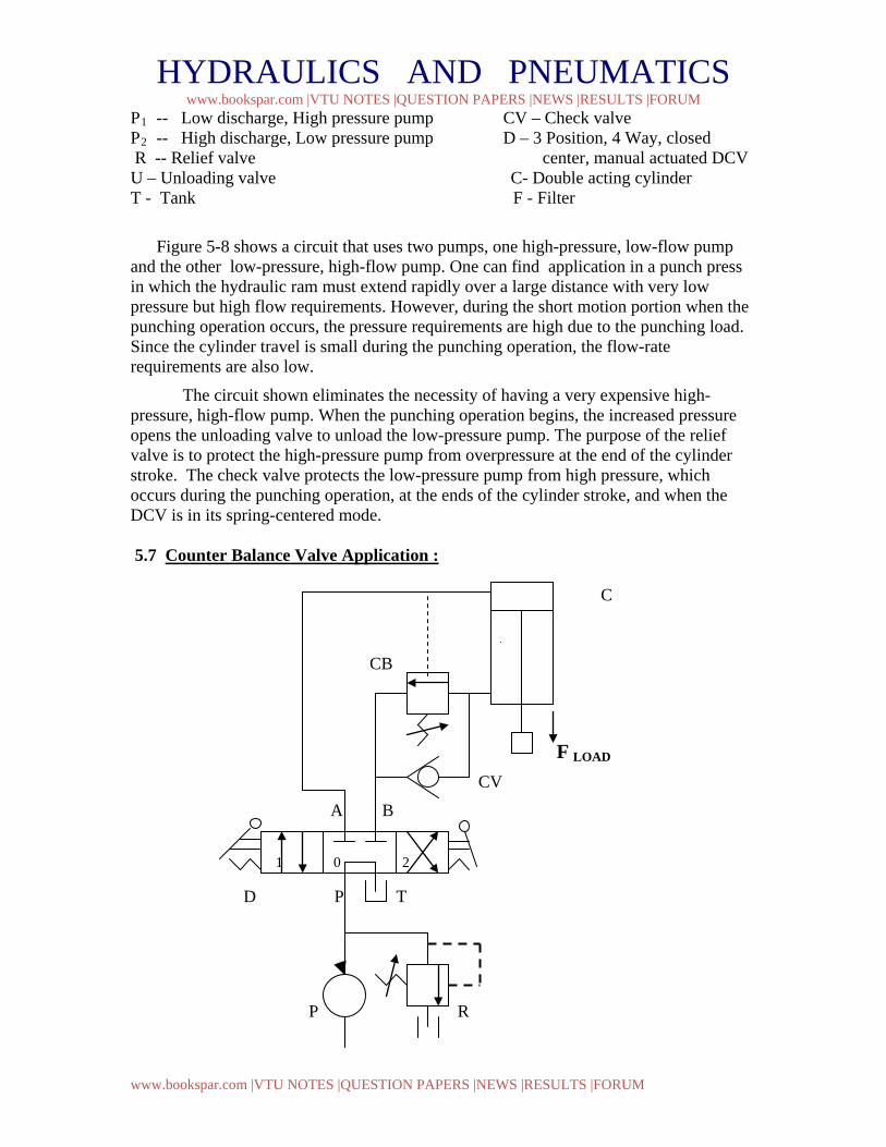
Figure 5-8 shows a circuit that uses two pumps, one high-pressure, low-flow pump and the other low-pressure, high-flow pump. One can find application in a punch press in which the hydraulic ram must extend rapidly over a large distance with very low pressure but high flow requirements. However, during the short motion portion when the punching operation occurs, the pressure requirements are high due to the punching load. Since the cylinder travel is small during the punching operation, the flow-rate requirements are also low.
The circuit shown eliminates the necessity of having a very expensive high-pressure, high-flow pump. When the punching operation begins, the increased pressure opens the unloading valve to unload the low-pressure pump. The purpose of the relief valve is to protect the high-pressure pump from overpressure at the end of the cylinder stroke. The check valve protects the low-pressure pump from high pressure, which occurs during the punching operation, at the ends of the cylinder stroke, and when the DCV is in its spring-centered mode.
5.7 Counter Balance Valve Application :
C
CB
F LOAD
CV
A B
D P T
P R
1 0 2
HYDRAULICS AND PNEUMATICS www.bookspar.com |VTU NOTES |QUESTION PAPERS |NEWS |RESULTS |FORUM
www.bookspar.com |VTU NOTES |QUESTION PAPERS |NEWS |RESULTS |FORUM
T
F
T
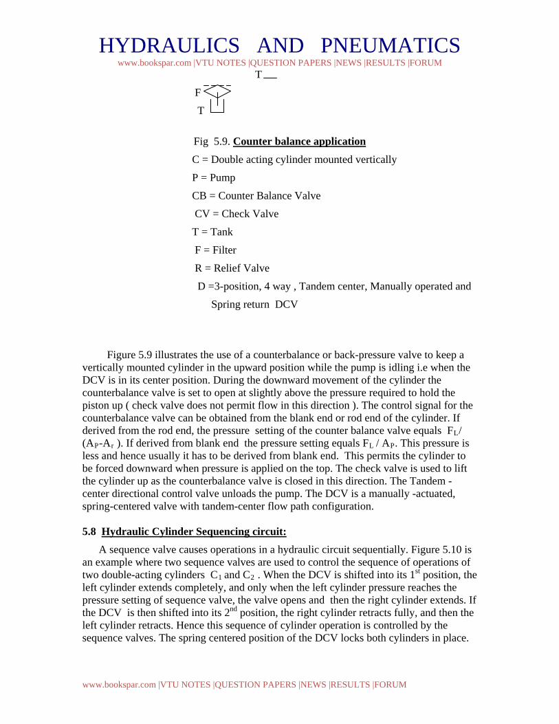
Fig 5.9. Counter balance application
C = Double acting cylinder mounted vertically
P = Pump
CB = Counter Balance Valve
CV = Check Valve
T = Tank
F = Filter
R = Relief Valve
D =3-position, 4 way , Tandem center, Manually operated and
Spring return DCV
Figure 5.9 illustrates the use of a counterbalance or back-pressure valve to keep a vertically mounted cylinder in the upward position while the pump is idling i.e when the DCV is in its center position. During the downward movement of the cylinder the counterbalance valve is set to open at slightly above the pressure required to hold the piston up ( check valve does not permit flow in this direction ). The control signal for the counterbalance valve can be obtained from the blank end or rod end of the cylinder. If derived from the rod end, the pressure setting of the counter balance valve equals FL/ (AP-Ar ). If derived from blank end the pressure setting equals FL / AP. This pressure is less and hence usually it has to be derived from blank end. This permits the cylinder to be forced downward when pressure is applied on the top. The check valve is used to lift the cylinder up as the counterbalance valve is closed in this direction. The Tandem -center directional control valve unloads the pump. The DCV is a manually -actuated, spring-centered valve with tandem-center flow path configuration. 5.8 Hydraulic Cylinder Sequencing circuit: A sequence valve causes operations in a hydraulic circuit sequentially. Figure 5.10 is an example where two sequence valves are used to control the sequence of operations of two double-acting cylinders C1 and C2 . When the DCV is shifted into its 1st position, the left cylinder extends completely, and only when the left cylinder pressure reaches the pressure setting of sequence valve, the valve opens and then the right cylinder extends. If the DCV is then shifted into its 2nd position, the right cylinder retracts fully, and then the left cylinder retracts. Hence this sequence of cylinder operation is controlled by the sequence valves. The spring centered position of the DCV locks both cylinders in place.
HYDRAULICS AND PNEUMATICS www.bookspar.com |VTU NOTES |QUESTION PAPERS |NEWS |RESULTS |FORUM
www.bookspar.com |VTU NOTES |QUESTION PAPERS |NEWS |RESULTS |FORUM
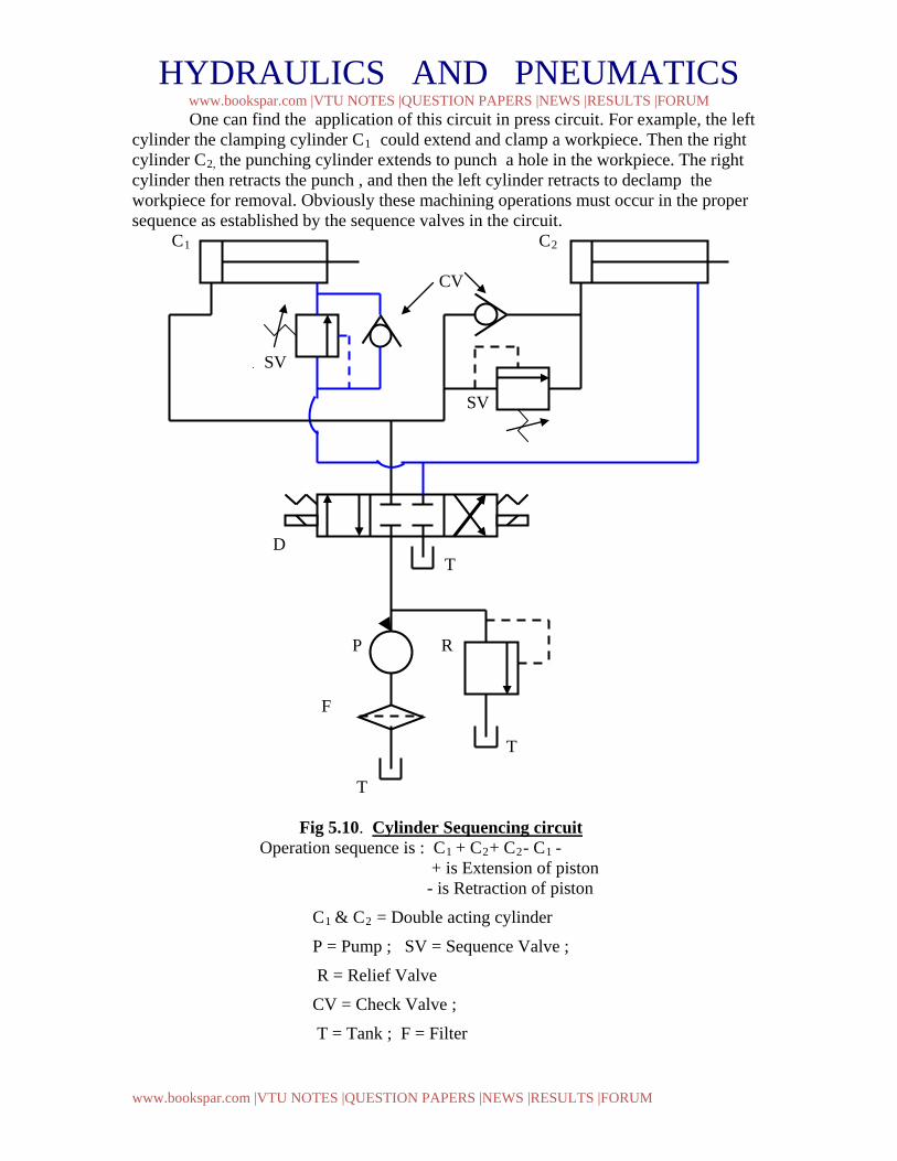
One can find the application of this circuit in press circuit. For example, the left cylinder the clamping cylinder C1 could extend and clamp a workpiece. Then the right cylinder C2, the punching cylinder extends to punch a hole in the workpiece. The right cylinder then retracts the punch , and then the left cylinder retracts to declamp the workpiece for removal. Obviously these machining operations must occur in the proper sequence as established by the sequence valves in the circuit. C1 C2
CV
SV SV D T P R F T T Fig 5.10. Cylinder Sequencing circuit Operation sequence is : C1 + C2+ C2- C1 - + is Extension of piston - is Retraction of piston
C1 & C2 = Double acting cylinder
P = Pump ; SV = Sequence Valve ;
R = Relief Valve
CV = Check Valve ;
T = Tank ; F = Filter
HYDRAULICS AND PNEUMATICS www.bookspar.com |VTU NOTES |QUESTION PAPERS |NEWS |RESULTS |FORUM
www.bookspar.com |VTU NOTES |QUESTION PAPERS |NEWS |RESULTS |FORUM
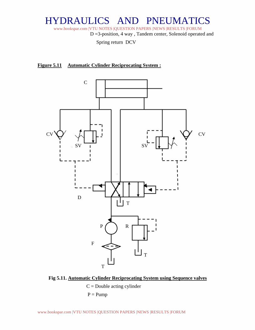
D =3-position, 4 way , Tandem center, Solenoid operated and
Spring return DCV
Figure 5.11 Automatic Cylinder Reciprocating System : C
CV CV SV SV D T P R F T T
Fig 5.11. Automatic Cylinder Reciprocating System using Sequence valves C = Double acting cylinder
P = Pump
HYDRAULICS AND PNEUMATICS www.bookspar.com |VTU NOTES |QUESTION PAPERS |NEWS |RESULTS |FORUM
www.bookspar.com |VTU NOTES |QUESTION PAPERS |NEWS |RESULTS |FORUM
SV = Sequence Valve
CV = Check Valve ; R = Relief Valve
T = Tank ; F = Filter
D =2-position, 4 way , pilot operated DCV
Figure 5.11 shows a circuit that produces continuous automatic reciprocation of a hydraulic cylinder. This is accomplished by using two sequence valves, each of which senses a stroke completion by the corresponding buildup of pressure. Each check valve and corresponding pilot line prevents shifting of the four-way valve until the particular stroke of the cylinder has been completed. The check valves are needed to allow pilot oil to leave either end of the DCV while pilot pressure is applied to the opposite end. This permits the spool of the DCV to shift as required.
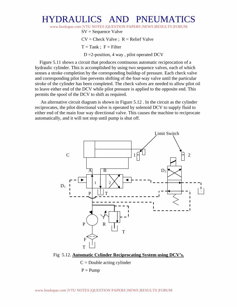
An alternative circuit diagram is shown in Figure 5.12 . In the circuit as the cylinder reciprocates, the pilot directional valve is operated by solenoid DCV to supply fluid to either end of the main four way directional valve. This causes the machine to reciprocate automatically, and it will not stop until pump is shut off.
Limit Switch
C 1 1 2
A B D2
D1
P T
P R
T
F
T
Fig 5.12. Automatic Cylinder Reciprocating System using DCV’s. C = Double acting cylinder
P = Pump
1 2
HYDRAULICS AND PNEUMATICS www.bookspar.com |VTU NOTES |QUESTION PAPERS |NEWS |RESULTS |FORUM
www.bookspar.com |VTU NOTES |QUESTION PAPERS |NEWS |RESULTS |FORUM
R = Relief Valve
T = Tank ; F = Filter
D1 =2-position, 4 way , pilot operated DCV
D2 =2-position, 4 way , mechanical operated DCV
The limit switch 1 and 2 will alternatively energize and deenergize solenoid ,thereby changing the directional of fluid flow into the pilot
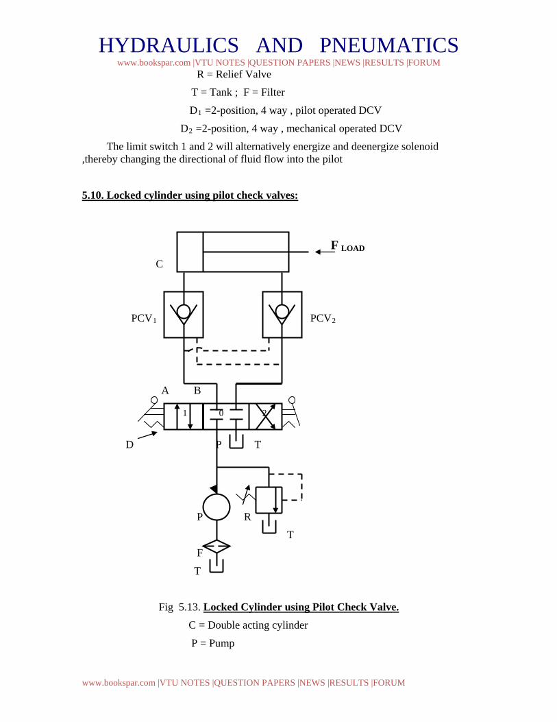
5.10. Locked cylinder using pilot check valves:
F LOAD
C
PCV1 PCV2
A B
D P T
P R
T
F
T
Fig 5.13. Locked Cylinder using Pilot Check Valve. C = Double acting cylinder
P = Pump
1 0 2
HYDRAULICS AND PNEUMATICS www.bookspar.com |VTU NOTES |QUESTION PAPERS |NEWS |RESULTS |FORUM
www.bookspar.com |VTU NOTES |QUESTION PAPERS |NEWS |RESULTS |FORUM
PCV1 & PCV2 = Pilot Check Valve
R = Relief Valve
T = Tank ; F = Filter
D =3-position, 4 way , closed center, manually operated DCV
In many cylinder applications, it is necessary to lock the cylinder so that its piston cannot be moved due to an external force acting on the piston rod. One method for locking a cylinder in this fashion is by using pilot check valves, as shown in Fig 5.13. The cylinder can be extended and retracted as normally done by the action of the directional control valve. If regular check valves were used, the cylinder could not be extended or retracted by the action of the DCV. An external force, acting on the piston rod, will not move the piston in either direction because reverse flow through either pilot check valve is not permitted under these conditions.
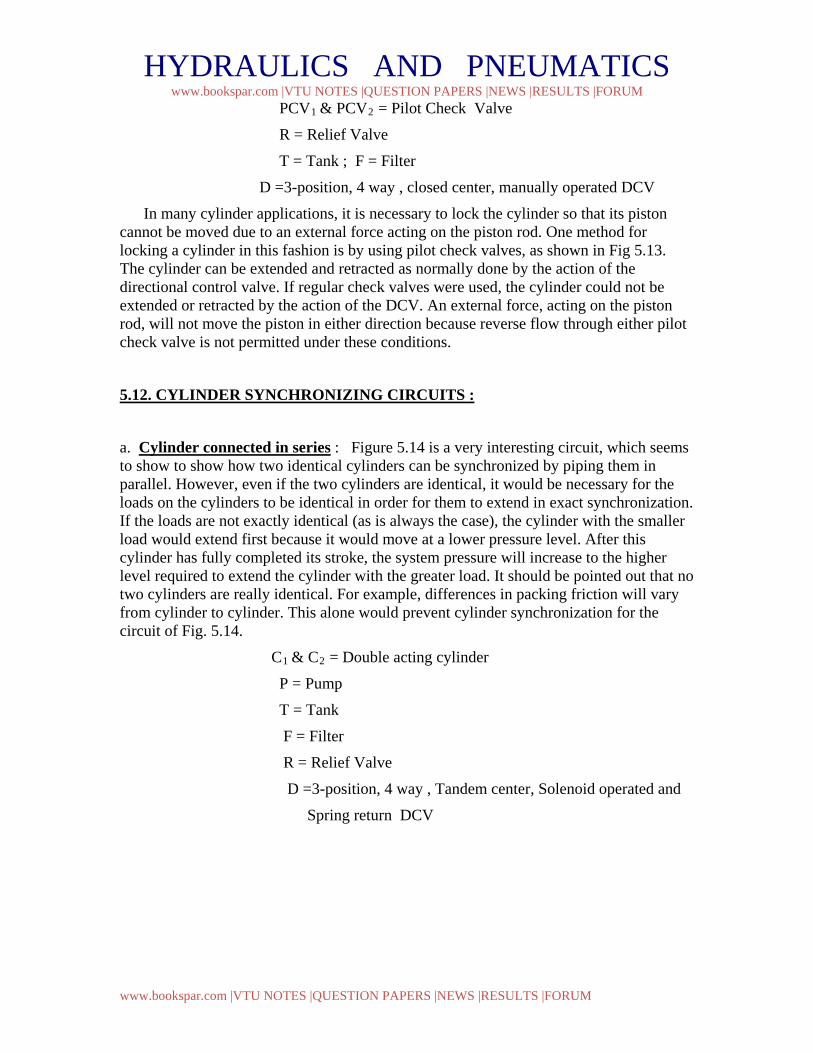
5.12. CYLINDER SYNCHRONIZING CIRCUITS :
a. Cylinder connected in series : Figure 5.14 is a very interesting circuit, which seems to show to show how two identical cylinders can be synchronized by piping them in parallel. However, even if the two cylinders are identical, it would be necessary for the loads on the cylinders to be identical in order for them to extend in exact synchronization. If the loads are not exactly identical (as is always the case), the cylinder with the smaller load would extend first because it would move at a lower pressure level. After this cylinder has fully completed its stroke, the system pressure will increase to the higher level required to extend the cylinder with the greater load. It should be pointed out that no two cylinders are really identical. For example, differences in packing friction will vary from cylinder to cylinder. This alone would prevent cylinder synchronization for the circuit of Fig. 5.14.
C1 & C2 = Double acting cylinder
P = Pump
T = Tank
F = Filter
R = Relief Valve
D =3-position, 4 way , Tandem center, Solenoid operated and
Spring return DCV
HYDRAULICS AND PNEUMATICS www.bookspar.com |VTU NOTES |QUESTION PAPERS |NEWS |RESULTS |FORUM
www.bookspar.com |VTU NOTES |QUESTION PAPERS |NEWS |RESULTS |FORUM
C1 F Load
C2
FLoad
A B
D P T
E P R
T
F
T
Fig 5.14. Cylinder hooked in parallel for synchronizing
(will not operate)
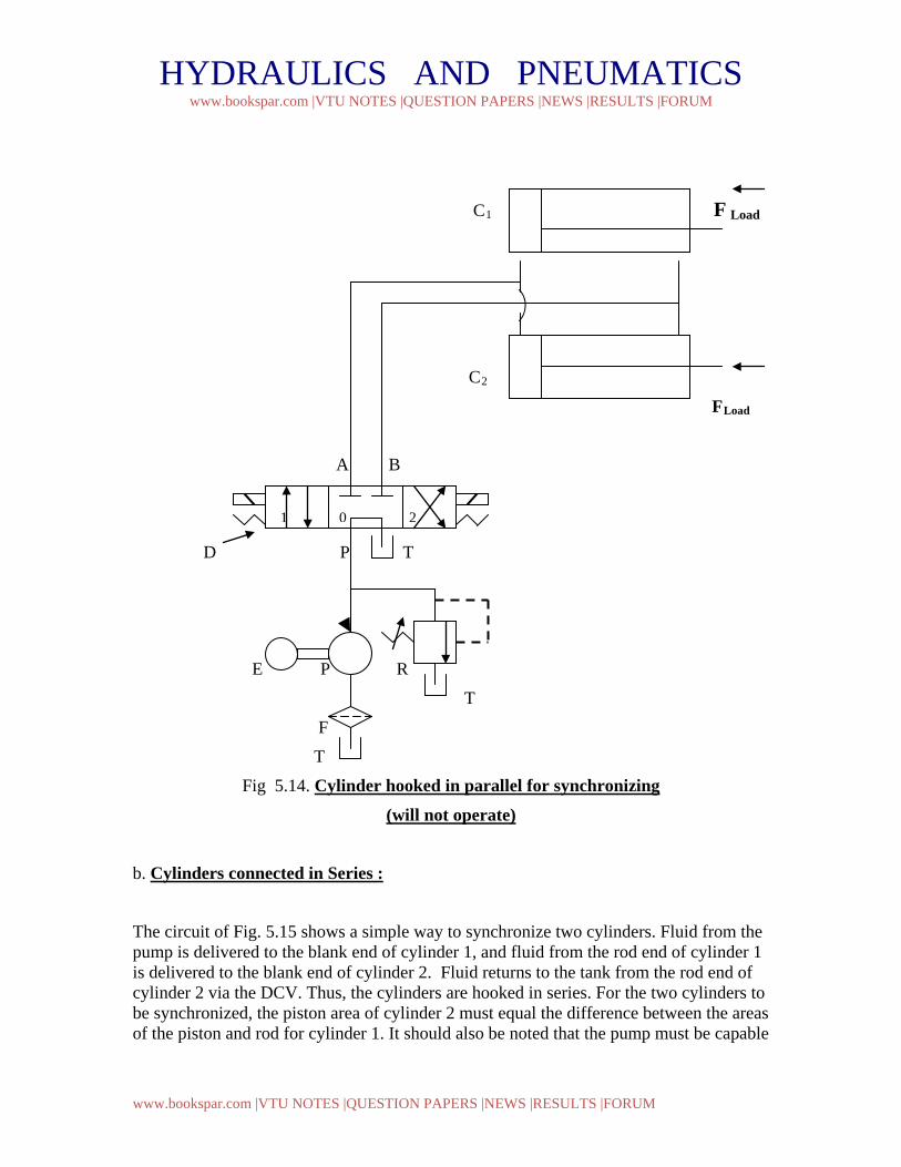
b. Cylinders connected in Series :
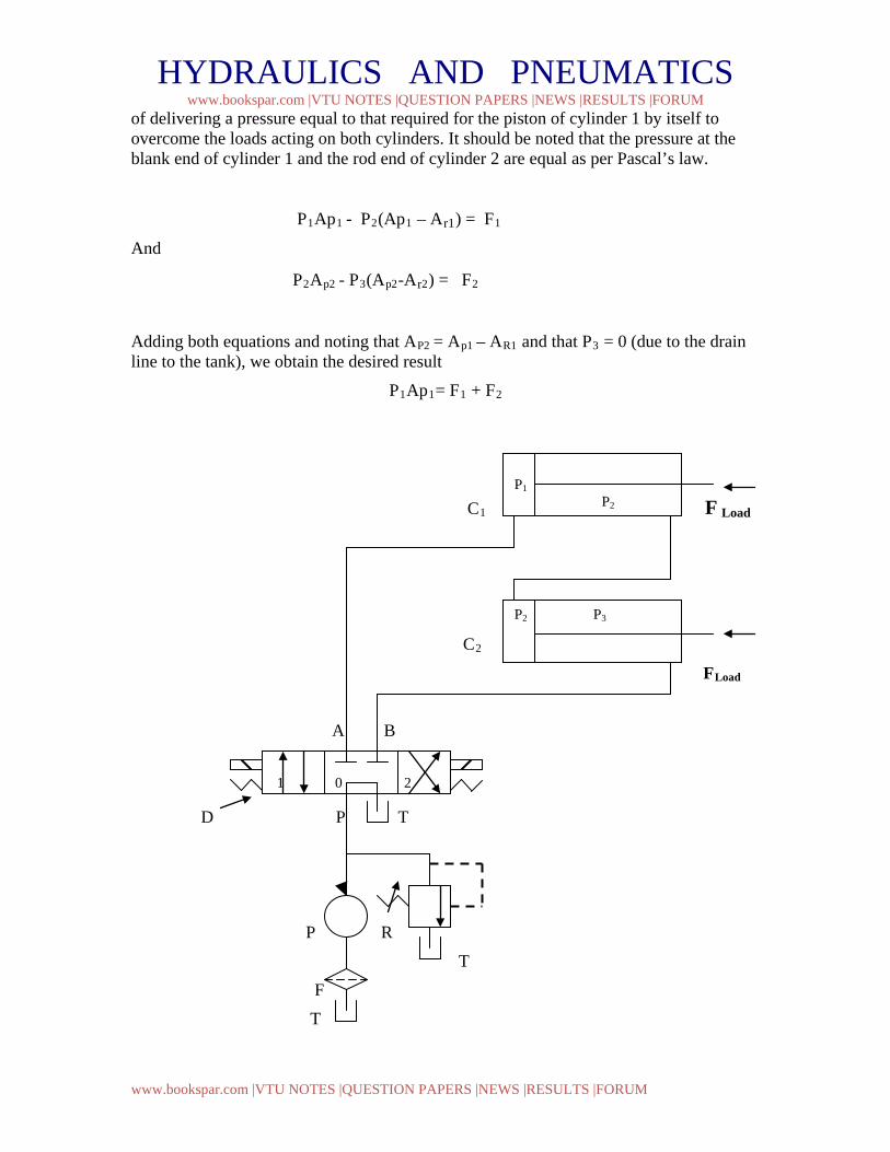
The circuit of Fig. 5.15 shows a simple way to synchronize two cylinders. Fluid from the pump is delivered to the blank end of cylinder 1, and fluid from the rod end of cylinder 1 is delivered to the blank end of cylinder 2. Fluid returns to the tank from the rod end of cylinder 2 via the DCV. Thus, the cylinders are hooked in series. For the two cylinders to be synchronized, the piston area of cylinder 2 must equal the difference between the areas of the piston and rod for cylinder 1. It should also be noted that the pump must be capable
1 0 2
HYDRAULICS AND PNEUMATICS www.bookspar.com |VTU NOTES |QUESTION PAPERS |NEWS |RESULTS |FORUM
www.bookspar.com |VTU NOTES |QUESTION PAPERS |NEWS |RESULTS |FORUM
of delivering a pressure equal to that required for the piston of cylinder 1 by itself to overcome the loads acting on both cylinders. It should be noted that the pressure at the blank end of cylinder 1 and the rod end of cylinder 2 are equal as per Pascal’s law.
P1Ap1 - P2(Ap1 – Ar1) = F1
And
P2Ap2 - P3(Ap2-Ar2) = F2
Adding both equations and noting that AP2 = Ap1 – AR1 and that P3 = 0 (due to the drain line to the tank), we obtain the desired result
P1Ap1= F1 + F2
C1 F Load
C2
FLoad
A B
D P T
P R
T
F
T
1 0 2
P2 P3
P1 P2
HYDRAULICS AND PNEUMATICS www.bookspar.com |VTU NOTES |QUESTION PAPERS |NEWS |RESULTS |FORUM
www.bookspar.com |VTU NOTES |QUESTION PAPERS |NEWS |RESULTS |FORUM
Fig 5.15. Cylinder hooked in Series for synchronizing
( Will Operate ) C1 & C2 = Double acting cylinder hooked in series
P = Pump
T = Tank
F = Filter
R = Relief Valve
D =3-position, 4 way , Tandem center, Solenoid operated and
Spring return DCV
HYDRAULICS AND PNEUMATICS www.bookspar.com |VTU NOTES |QUESTION PAPERS |NEWS |RESULTS |FORUM
www.bookspar.com |VTU NOTES |QUESTION PAPERS |NEWS |RESULTS |FORUM
CHAPTER 5. HYDRAULIC CIRCUIT DESIGN AND ANALYSIS -2
5.13 Speed control of Hydraulic Cylinder: Speed control of a hydraulic cylinder is accomplished using a flow control valve. A flow control valve regulate the speed of the cylinder by controlling the flow rate to and of the actuator. There are 3 types of speed control: • Meter- in circuit ( Primary control ) • Meter-out circuit ( Secondary control ) • Bleed - off circuit ( By pass control )
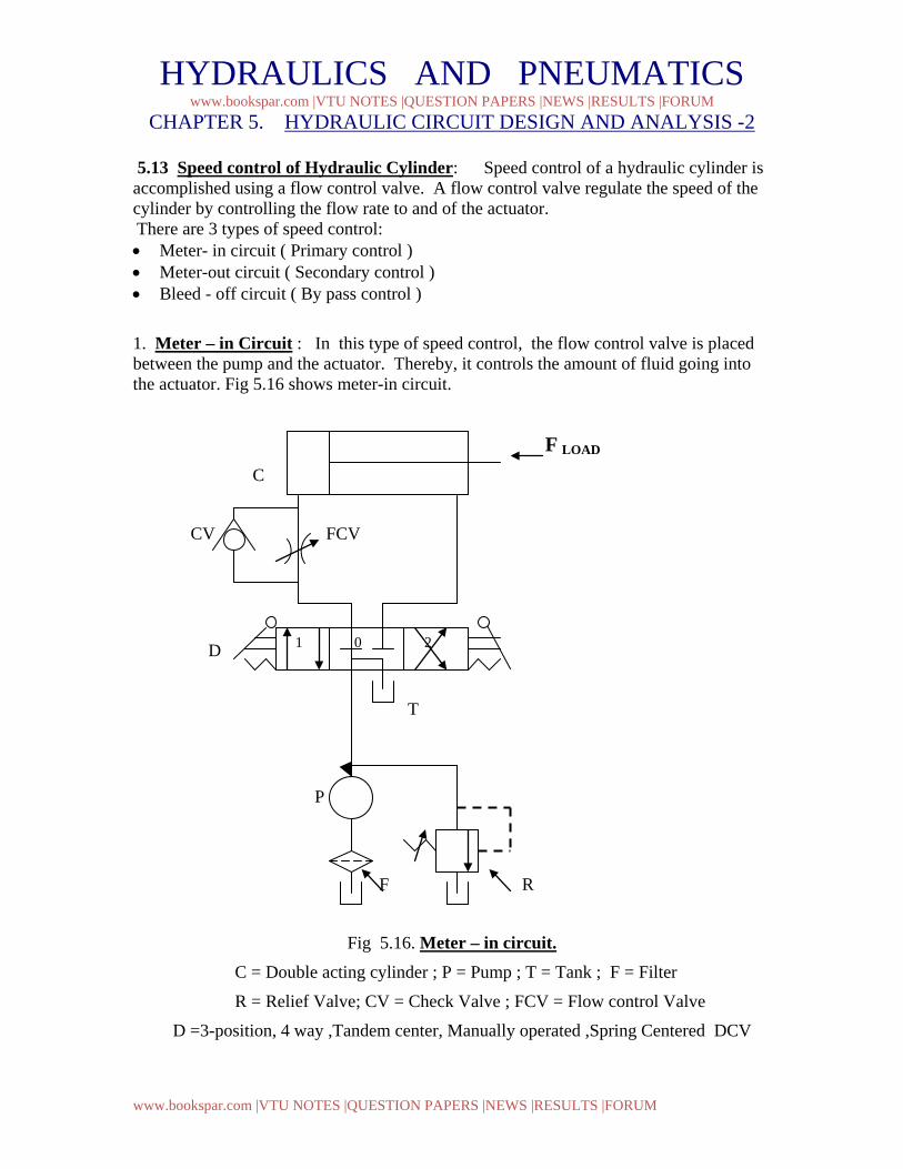
1. Meter – in Circuit : In this type of speed control, the flow control valve is placed between the pump and the actuator. Thereby, it controls the amount of fluid going into the actuator. Fig 5.16 shows meter-in circuit.
F LOAD
C
CV FCV
D
T
P
F R
Fig 5.16. Meter – in circuit. C = Double acting cylinder ; P = Pump ; T = Tank ; F = Filter
R = Relief Valve; CV = Check Valve ; FCV = Flow control Valve
D =3-position, 4 way ,Tandem center, Manually operated ,Spring Centered DCV
1 0 2
HYDRAULICS AND PNEUMATICS www.bookspar.com |VTU NOTES |QUESTION PAPERS |NEWS |RESULTS |FORUM
www.bookspar.com |VTU NOTES |QUESTION PAPERS |NEWS |RESULTS |FORUM
When the directional control valve is actuated to the 1st position, oil flows through the flow control valve to extend the cylinder. The extending speed of the cylinder depends on the setting (percent of full opening position) of the flow control valve.
When the directional control valve is actuated to the 2nd position, the cylinder retracts as oil flows from the cylinder to the oil tank through the check valve as well as the flow control valve.
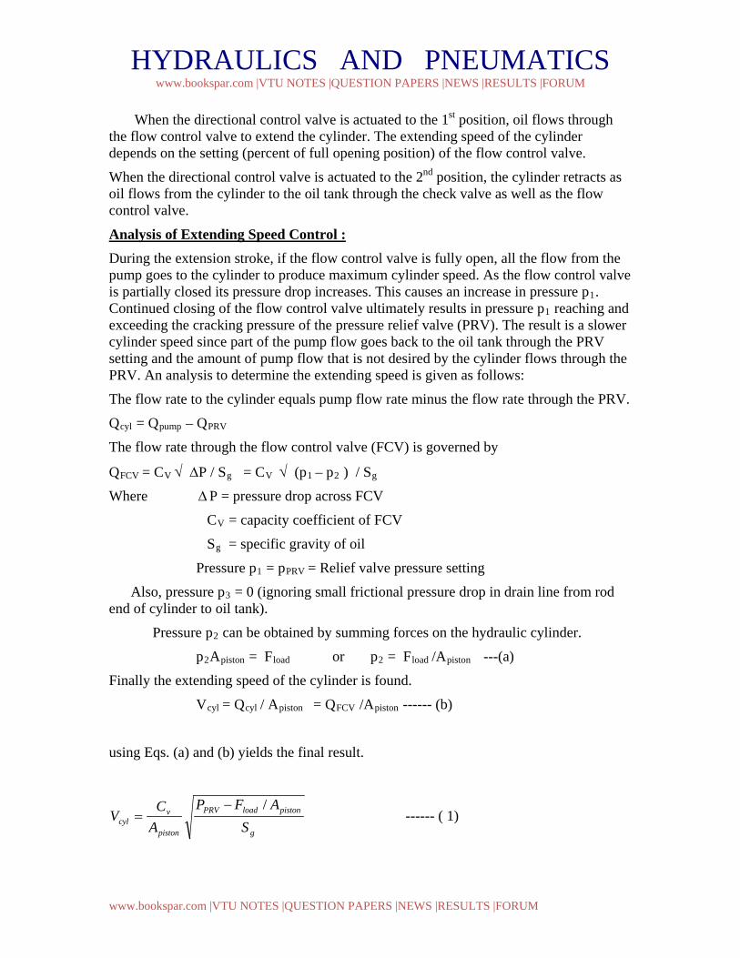
Analysis of Extending Speed Control : During the extension stroke, if the flow control valve is fully open, all the flow from the pump goes to the cylinder to produce maximum cylinder speed. As the flow control valve is partially closed its pressure drop increases. This causes an increase in pressure p1. Continued closing of the flow control valve ultimately results in pressure p1 reaching and exceeding the cracking pressure of the pressure relief valve (PRV). The result is a slower cylinder speed since part of the pump flow goes back to the oil tank through the PRV setting and the amount of pump flow that is not desired by the cylinder flows through the PRV. An analysis to determine the extending speed is given as follows:
The flow rate to the cylinder equals pump flow rate minus the flow rate through the PRV.
Qcyl = Qpump – QPRV
The flow rate through the flow control valve (FCV) is governed by
QFCV = CV √ ∆P / Sg = CV √ (p1 – p2 ) / Sg
Where ∆P = pressure drop across FCV
CV = capacity coefficient of FCV
Sg = specific gravity of oil
Pressure p1 = pPRV = Relief valve pressure setting
Also, pressure p3 = 0 (ignoring small frictional pressure drop in drain line from rod end of cylinder to oil tank).
Pressure p2 can be obtained by summing forces on the hydraulic cylinder.
p2Apiston = Fload or p2 = Fload /Apiston ---(a)
Finally the extending speed of the cylinder is found.
Vcyl = Qcyl / Apiston = QFCV /Apiston ------ (b)
using Eqs. (a) and (b) yields the final result.
g
pistonloadPRV
piston
vcyl S
AFPAC
V/−
= ------ ( 1)
HYDRAULICS AND PNEUMATICS www.bookspar.com |VTU NOTES |QUESTION PAPERS |NEWS |RESULTS |FORUM
www.bookspar.com |VTU NOTES |QUESTION PAPERS |NEWS |RESULTS |FORUM
As can be seen by Eq. 1, by varying the setting of the flow control system, and thus the value of CV, the desired extending speed of the cylinder can be achieved.
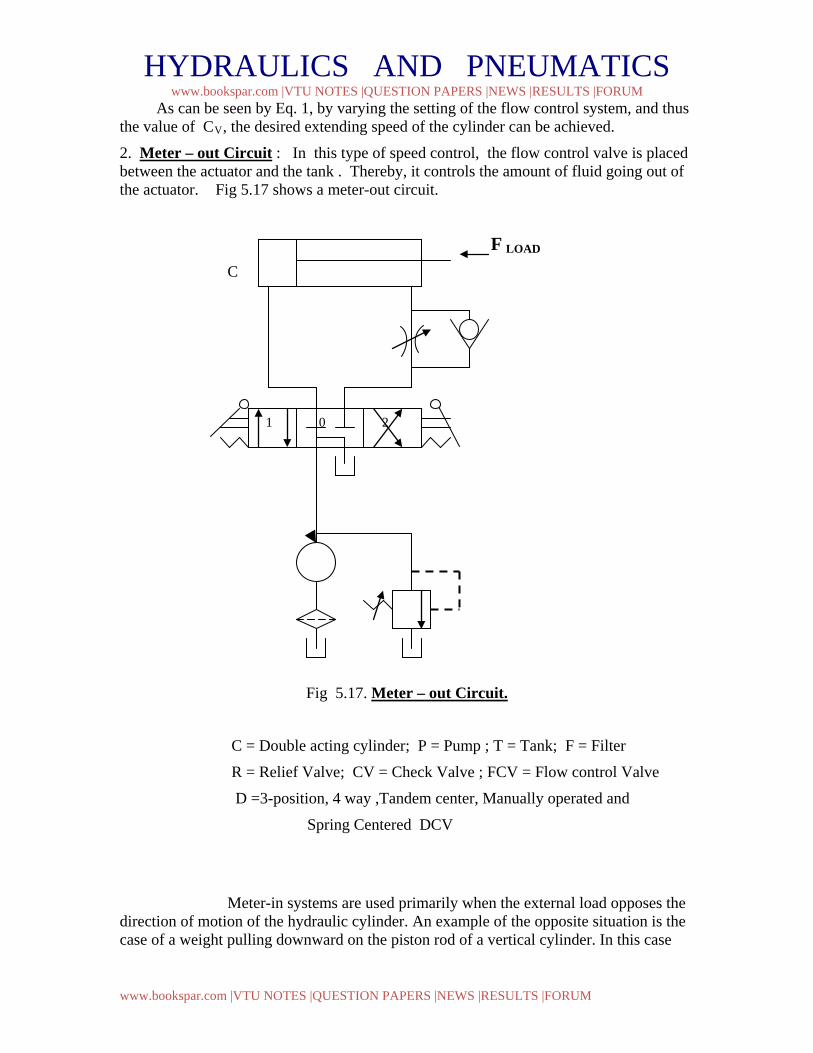
2. Meter – out Circuit : In this type of speed control, the flow control valve is placed between the actuator and the tank . Thereby, it controls the amount of fluid going out of the actuator. Fig 5.17 shows a meter-out circuit.
F LOAD
C
Fig 5.17. Meter – out Circuit.
C = Double acting cylinder; P = Pump ; T = Tank; F = Filter
R = Relief Valve; CV = Check Valve ; FCV = Flow control Valve
D =3-position, 4 way ,Tandem center, Manually operated and
Spring Centered DCV
Meter-in systems are used primarily when the external load opposes the direction of motion of the hydraulic cylinder. An example of the opposite situation is the case of a weight pulling downward on the piston rod of a vertical cylinder. In this case
1 0 2
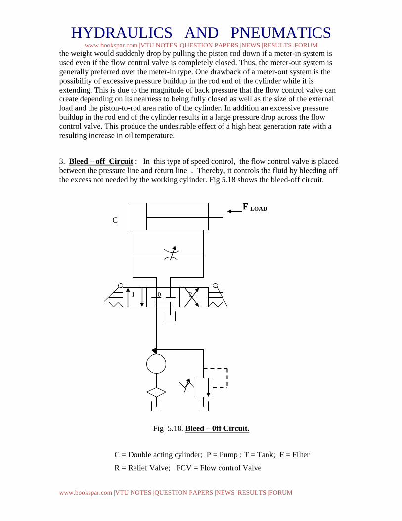
HYDRAULICS AND PNEUMATICS www.bookspar.com |VTU NOTES |QUESTION PAPERS |NEWS |RESULTS |FORUM
www.bookspar.com |VTU NOTES |QUESTION PAPERS |NEWS |RESULTS |FORUM
the weight would suddenly drop by pulling the piston rod down if a meter-in system is used even if the flow control valve is completely closed. Thus, the meter-out system is generally preferred over the meter-in type. One drawback of a meter-out system is the possibility of excessive pressure buildup in the rod end of the cylinder while it is extending. This is due to the magnitude of back pressure that the flow control valve can create depending on its nearness to being fully closed as well as the size of the external load and the piston-to-rod area ratio of the cylinder. In addition an excessive pressure buildup in the rod end of the cylinder results in a large pressure drop across the flow control valve. This produce the undesirable effect of a high heat generation rate with a resulting increase in oil temperature.
3. Bleed – off Circuit : In this type of speed control, the flow control valve is placed between the pressure line and return line . Thereby, it controls the fluid by bleeding off the excess not needed by the working cylinder. Fig 5.18 shows the bleed-off circuit.
F LOAD
C
Fig 5.18. Bleed – 0ff Circuit.
C = Double acting cylinder; P = Pump ; T = Tank; F = Filter
R = Relief Valve; FCV = Flow control Valve
1 0 2
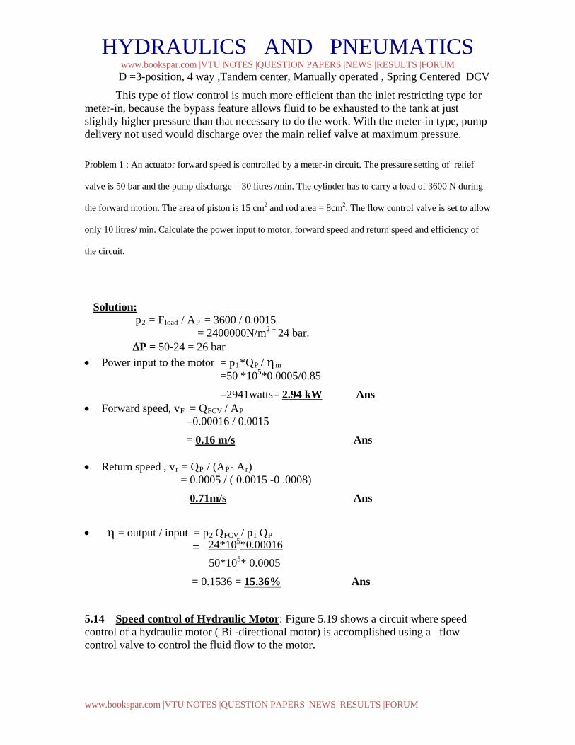
HYDRAULICS AND PNEUMATICS www.bookspar.com |VTU NOTES |QUESTION PAPERS |NEWS |RESULTS |FORUM
www.bookspar.com |VTU NOTES |QUESTION PAPERS |NEWS |RESULTS |FORUM
D =3-position, 4 way ,Tandem center, Manually operated , Spring Centered DCV
This type of flow control is much more efficient than the inlet restricting type for meter-in, because the bypass feature allows fluid to be exhausted to the tank at just slightly higher pressure than that necessary to do the work. With the meter-in type, pump delivery not used would discharge over the main relief valve at maximum pressure.
Problem 1 : An actuator forward speed is controlled by a meter-in circuit. The pressure setting of relief
valve is 50 bar and the pump discharge = 30 litres /min. The cylinder has to carry a load of 3600 N during
the forward motion. The area of piston is 15 cm2 and rod area = 8cm2. The flow control valve is set to allow
only 10 litres/ min. Calculate the power input to motor, forward speed and return speed and efficiency of
the circuit.
Solution: p2 = Fload / AP = 3600 / 0.0015 = 2400000N/m2 = 24 bar. ∆P = 50-24 = 26 bar • Power input to the motor = p1*QP / ηm
=50 *105*0.0005/0.85
=2941watts= 2.94 kW Ans • Forward speed, vF = QFCV / AP
=0.00016 / 0.0015
= 0.16 m/s Ans • Return speed , vr = QP / (AP- Ar) = 0.0005 / ( 0.0015 -0 .0008)
= 0.71m/s Ans • η = output / input = p2 QFCV / p1 QP = 24*105*0.00016 50*105* 0.0005
= 0.1536 = 15.36% Ans
5.14 Speed control of Hydraulic Motor: Figure 5.19 shows a circuit where speed control of a hydraulic motor ( Bi -directional motor) is accomplished using a flow control valve to control the fluid flow to the motor.
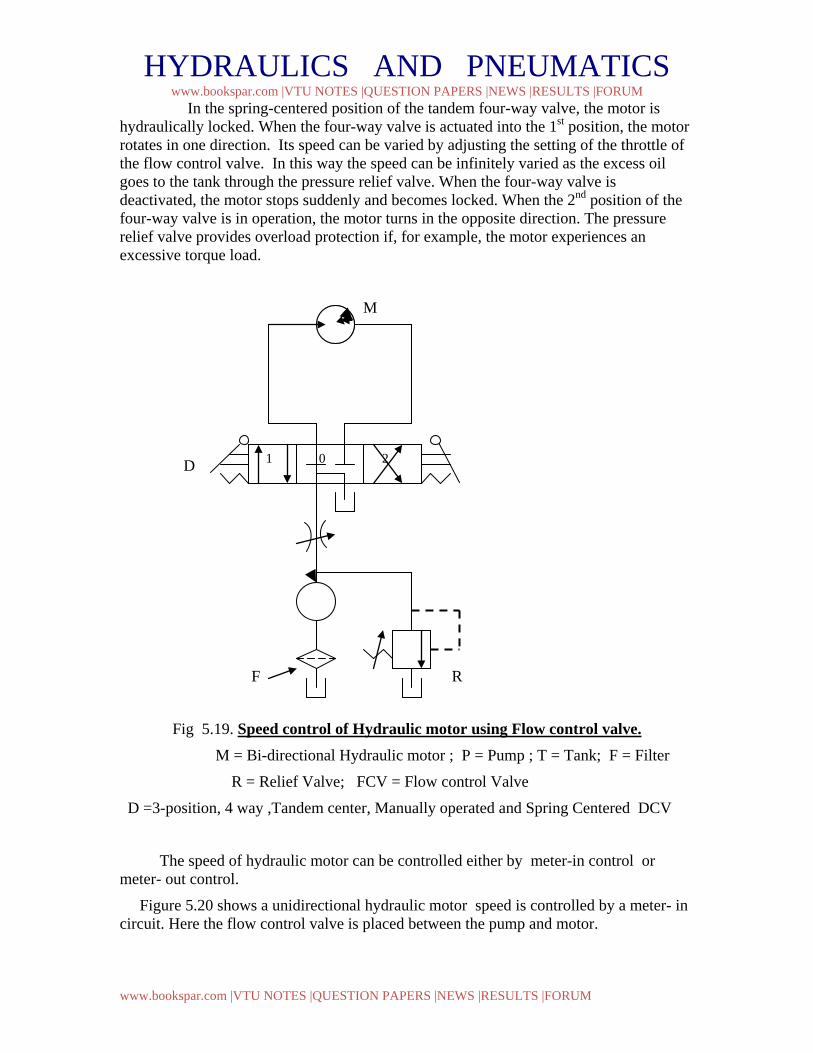
HYDRAULICS AND PNEUMATICS www.bookspar.com |VTU NOTES |QUESTION PAPERS |NEWS |RESULTS |FORUM
www.bookspar.com |VTU NOTES |QUESTION PAPERS |NEWS |RESULTS |FORUM
In the spring-centered position of the tandem four-way valve, the motor is hydraulically locked. When the four-way valve is actuated into the 1st position, the motor rotates in one direction. Its speed can be varied by adjusting the setting of the throttle of the flow control valve. In this way the speed can be infinitely varied as the excess oil goes to the tank through the pressure relief valve. When the four-way valve is deactivated, the motor stops suddenly and becomes locked. When the 2nd position of the four-way valve is in operation, the motor turns in the opposite direction. The pressure relief valve provides overload protection if, for example, the motor experiences an excessive torque load.
M
D
F R
Fig 5.19. Speed control of Hydraulic motor using Flow control valve. M = Bi-directional Hydraulic motor ; P = Pump ; T = Tank; F = Filter
R = Relief Valve; FCV = Flow control Valve
D =3-position, 4 way ,Tandem center, Manually operated and Spring Centered DCV
The speed of hydraulic motor can be controlled either by meter-in control or meter- out control.
Figure 5.20 shows a unidirectional hydraulic motor speed is controlled by a meter- in circuit. Here the flow control valve is placed between the pump and motor.
1 0 2
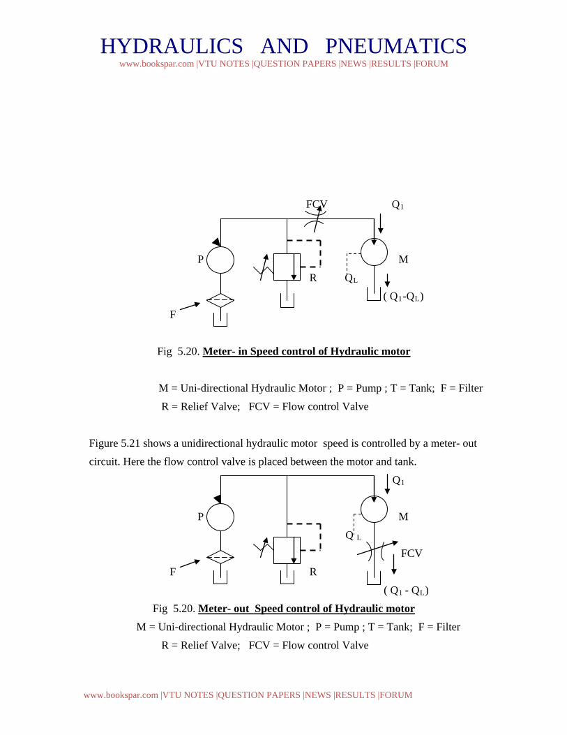
HYDRAULICS AND PNEUMATICS www.bookspar.com |VTU NOTES |QUESTION PAPERS |NEWS |RESULTS |FORUM
www.bookspar.com |VTU NOTES |QUESTION PAPERS |NEWS |RESULTS |FORUM
FCV Q1
P M
R QL
( Q1-QL)
F
Fig 5.20. Meter- in Speed control of Hydraulic motor
M = Uni-directional Hydraulic Motor ; P = Pump ; T = Tank; F = Filter
R = Relief Valve; FCV = Flow control Valve
Figure 5.21 shows a unidirectional hydraulic motor speed is controlled by a meter- out
circuit. Here the flow control valve is placed between the motor and tank.
Q1
P M
Q L
FCV
F R
( Q1 - QL)
Fig 5.20. Meter- out Speed control of Hydraulic motor M = Uni-directional Hydraulic Motor ; P = Pump ; T = Tank; F = Filter
R = Relief Valve; FCV = Flow control Valve
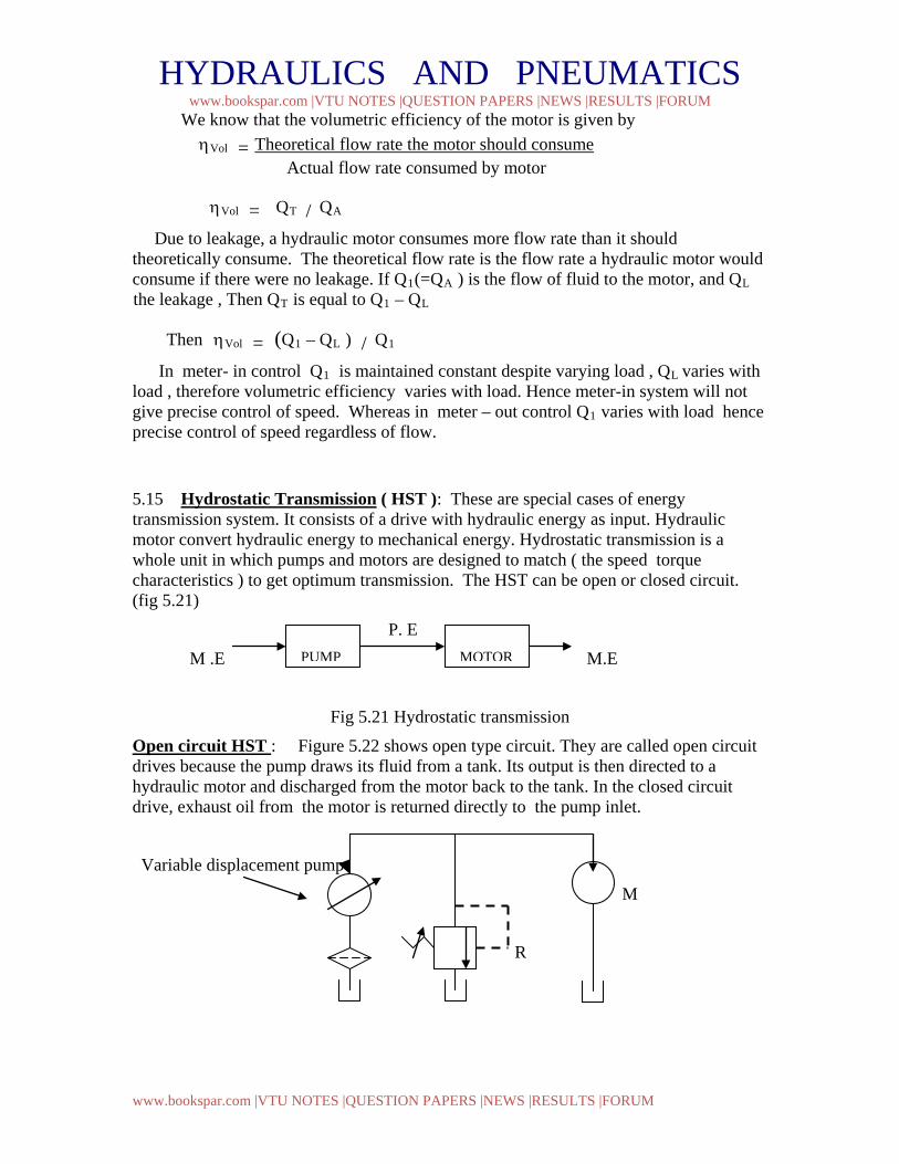
HYDRAULICS AND PNEUMATICS www.bookspar.com |VTU NOTES |QUESTION PAPERS |NEWS |RESULTS |FORUM
www.bookspar.com |VTU NOTES |QUESTION PAPERS |NEWS |RESULTS |FORUM
We know that the volumetric efficiency of the motor is given by ηVol = Theoretical flow rate the motor should consume Actual flow rate consumed by motor
ηVol = QT / QA
Due to leakage, a hydraulic motor consumes more flow rate than it should theoretically consume. The theoretical flow rate is the flow rate a hydraulic motor would consume if there were no leakage. If Q1(=QA ) is the flow of fluid to the motor, and QL the leakage , Then QT is equal to Q1 – QL
Then ηVol = (Q1 – QL ) / Q1
In meter- in control Q1 is maintained constant despite varying load , QL varies with load , therefore volumetric efficiency varies with load. Hence meter-in system will not give precise control of speed. Whereas in meter – out control Q1 varies with load hence precise control of speed regardless of flow.
5.15 Hydrostatic Transmission ( HST ): These are special cases of energy transmission system. It consists of a drive with hydraulic energy as input. Hydraulic motor convert hydraulic energy to mechanical energy. Hydrostatic transmission is a whole unit in which pumps and motors are designed to match ( the speed torque characteristics ) to get optimum transmission. The HST can be open or closed circuit. (fig 5.21) P. E
M .E M.E
Fig 5.21 Hydrostatic transmission
Open circuit HST : Figure 5.22 shows open type circuit. They are called open circuit drives because the pump draws its fluid from a tank. Its output is then directed to a hydraulic motor and discharged from the motor back to the tank. In the closed circuit drive, exhaust oil from the motor is returned directly to the pump inlet.
Variable displacement pump
M
R
PUMP
MOTOR
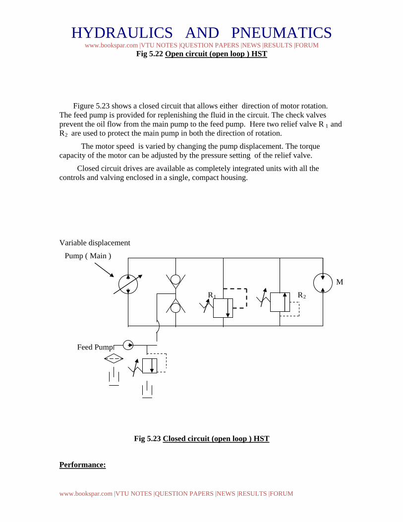
HYDRAULICS AND PNEUMATICS www.bookspar.com |VTU NOTES |QUESTION PAPERS |NEWS |RESULTS |FORUM
www.bookspar.com |VTU NOTES |QUESTION PAPERS |NEWS |RESULTS |FORUM
Fig 5.22 Open circuit (open loop ) HST
Figure 5.23 shows a closed circuit that allows either direction of motor rotation. The feed pump is provided for replenishing the fluid in the circuit. The check valves prevent the oil flow from the main pump to the feed pump. Here two relief valve R 1 and R2 are used to protect the main pump in both the direction of rotation.
The motor speed is varied by changing the pump displacement. The torque capacity of the motor can be adjusted by the pressure setting of the relief valve.
Closed circuit drives are available as completely integrated units with all the controls and valving enclosed in a single, compact housing.
Variable displacement
Pump ( Main )
M
R1 R2
Feed Pump
Fig 5.23 Closed circuit (open loop ) HST Performance:
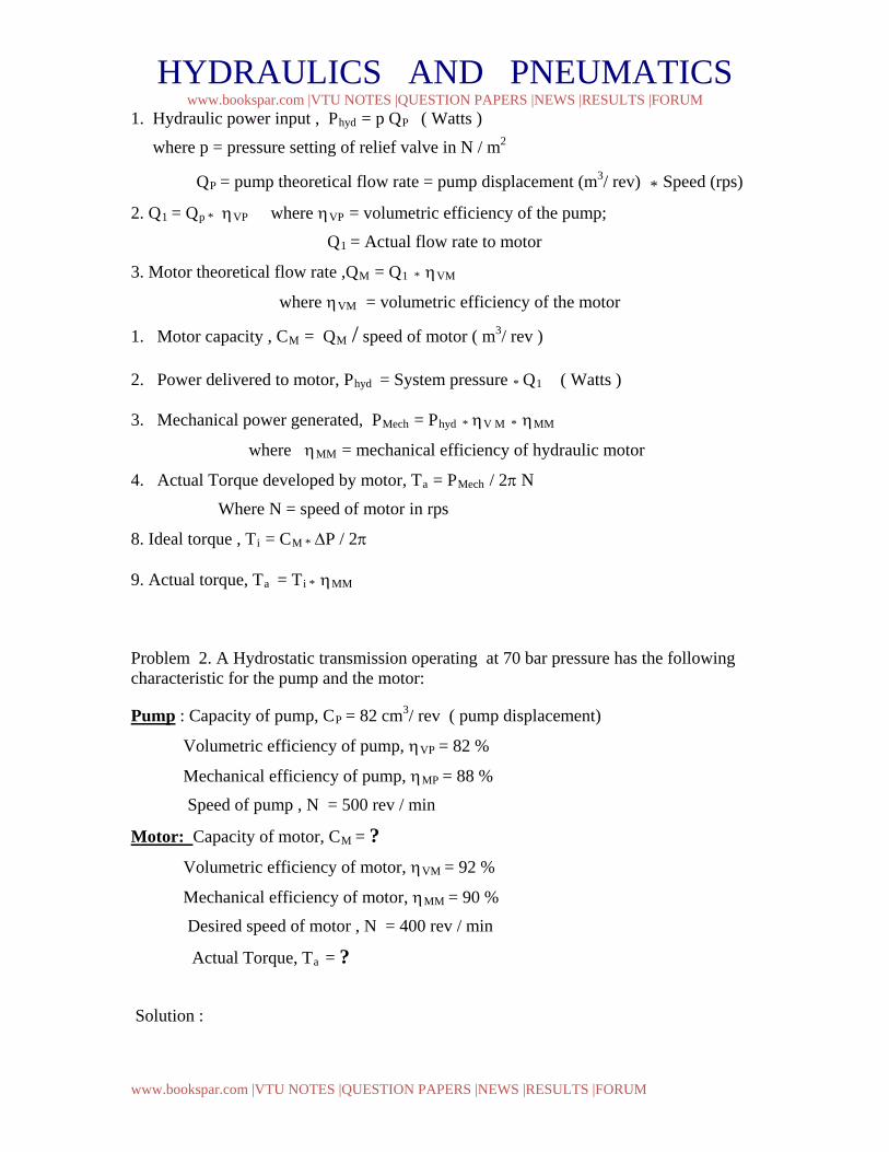
HYDRAULICS AND PNEUMATICS www.bookspar.com |VTU NOTES |QUESTION PAPERS |NEWS |RESULTS |FORUM
www.bookspar.com |VTU NOTES |QUESTION PAPERS |NEWS |RESULTS |FORUM
1. Hydraulic power input , Phyd = p QP ( Watts )
where p = pressure setting of relief valve in N / m2
QP = pump theoretical flow rate = pump displacement (m3/ rev) * Speed (rps)
2. Q1 = Qp * ηVP where ηVP = volumetric efficiency of the pump;
Q1 = Actual flow rate to motor
3. Motor theoretical flow rate ,QM = Q1 * ηVM
where ηVM = volumetric efficiency of the motor
1. Motor capacity , CM = QM / speed of motor ( m3/ rev )
2. Power delivered to motor, Phyd = System pressure * Q1 ( Watts )
3. Mechanical power generated, PMech = Phyd * ηV M * ηMM
where ηMM = mechanical efficiency of hydraulic motor
4. Actual Torque developed by motor, Ta = PMech / 2π N
Where N = speed of motor in rps
8. Ideal torque , Ti = CM * ∆P / 2π
9. Actual torque, Ta = Ti * ηMM
Problem 2. A Hydrostatic transmission operating at 70 bar pressure has the following characteristic for the pump and the motor:
Pump : Capacity of pump, CP = 82 cm3/ rev ( pump displacement)
Volumetric efficiency of pump, ηVP = 82 %
Mechanical efficiency of pump, ηMP = 88 %
Speed of pump , N = 500 rev / min
Motor: Capacity of motor, CM = ? Volumetric efficiency of motor, ηVM = 92 %
Mechanical efficiency of motor, ηMM = 90 %
Desired speed of motor , N = 400 rev / min
Actual Torque, Ta = ?
Solution :
HYDRAULICS AND PNEUMATICS www.bookspar.com |VTU NOTES |QUESTION PAPERS |NEWS |RESULTS |FORUM
www.bookspar.com |VTU NOTES |QUESTION PAPERS |NEWS |RESULTS |FORUM
Pump theoretical flow rate, QP = pump displacement * speed
= 82 * 10 - 06 * 500 / 60
= 0.00068 m3 / sec
Actual flow rate to the motor , Q1 = QP * ηVP
= 0.00068 * 0.82
= 0. 00056 m3 / sec
Motor theoretical flow rate, QM = Q1 * ηVM
= 0.00056 * 0.92
= 0. 000515 m3 / sec
• Motor capacity, CM = QM / speed of motor
= 0.000515 / 400/60
= 0.0000773 m3 / sec Ans
Power delivered to motor, Phyd = system pressure * Q1
= 70 * 105 * 0.00056
=3920 Watts = 3.92 kW
Mechanical power generated, PMech = Phyd * ηV M * ηMM
= 3.92 * 0.92 * 0.90
= 3.246 kW
• Actual Torque developed by motor, Ta = PMech / 2π N = 3.246*1000 / (2 π* 400 )
60 = 77.49 N- m Ans
Ideal torque , Ti = CM * ∆P / 2π
= 0.0000773 * 70 *105 / 2π
= 86.1 N-m
• Actual torque, Ta = Ti * ηMM
= 86.1 * 0.90
= 77.49 N –m Ans
HYDRAULICS AND PNEUMATICS www.bookspar.com |VTU NOTES |QUESTION PAPERS |NEWS |RESULTS |FORUM
www.bookspar.com |VTU NOTES |QUESTION PAPERS |NEWS |RESULTS |FORUM
ACCUMULATORS AND ACCUMULATOR CIRCUITS:
A hydraulic accumulator is a device that stores the potential energy of an incompressible fluid held under pressure by an external source against some dynamic force. The dynamic force can come three different sources : Gravity, Mechanical Springs, and Compressed gases. The stored potential energy in the accumulator is a quick secondary source of fluid power capable of doing useful work as required by the system.
There are three basic types of accumulator used in hydraulic system. They are:
1. Weight – Loaded, or gravity, type
2. Spring -Loaded type
3. Gas – Loaded type
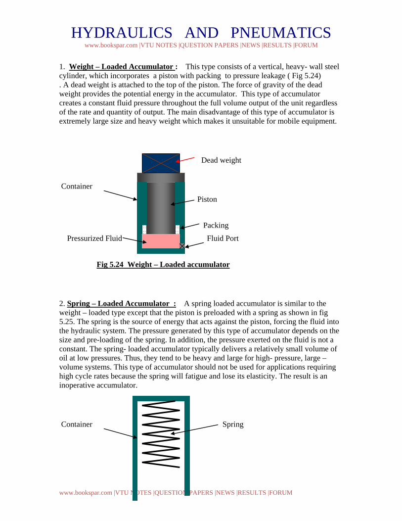
HYDRAULICS AND PNEUMATICS www.bookspar.com |VTU NOTES |QUESTION PAPERS |NEWS |RESULTS |FORUM
www.bookspar.com |VTU NOTES |QUESTION PAPERS |NEWS |RESULTS |FORUM
1. Weight – Loaded Accumulator : This type consists of a vertical, heavy- wall steel cylinder, which incorporates a piston with packing to pressure leakage ( Fig 5.24) . A dead weight is attached to the top of the piston. The force of gravity of the dead weight provides the potential energy in the accumulator. This type of accumulator creates a constant fluid pressure throughout the full volume output of the unit regardless of the rate and quantity of output. The main disadvantage of this type of accumulator is extremely large size and heavy weight which makes it unsuitable for mobile equipment.
Dead weight
Container
Piston
Packing
Pressurized Fluid Fluid Port
Fig 5.24 Weight – Loaded accumulator
2. Spring – Loaded Accumulator : A spring loaded accumulator is similar to the weight – loaded type except that the piston is preloaded with a spring as shown in fig 5.25. The spring is the source of energy that acts against the piston, forcing the fluid into the hydraulic system. The pressure generated by this type of accumulator depends on the size and pre-loading of the spring. In addition, the pressure exerted on the fluid is not a constant. The spring- loaded accumulator typically delivers a relatively small volume of oil at low pressures. Thus, they tend to be heavy and large for high- pressure, large –volume systems. This type of accumulator should not be used for applications requiring high cycle rates because the spring will fatigue and lose its elasticity. The result is an inoperative accumulator.
Container Spring
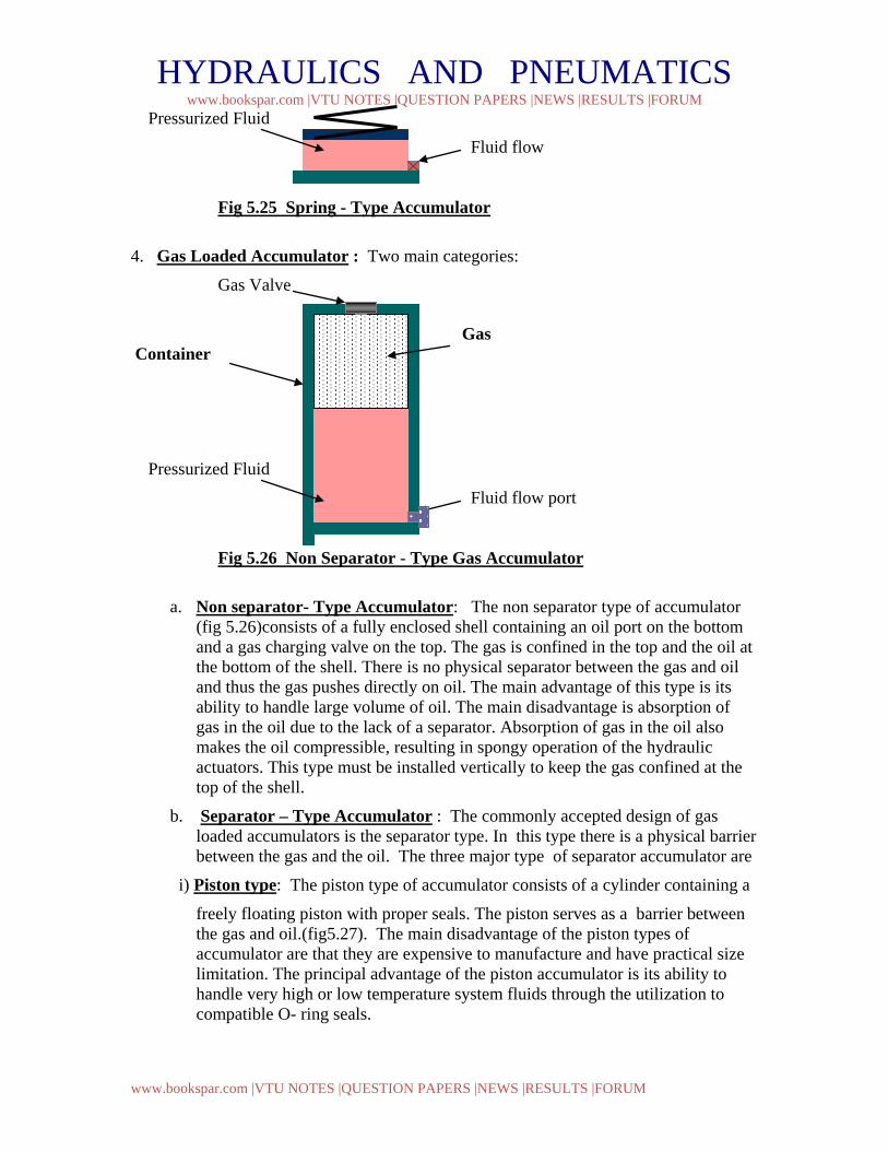
HYDRAULICS AND PNEUMATICS www.bookspar.com |VTU NOTES |QUESTION PAPERS |NEWS |RESULTS |FORUM
www.bookspar.com |VTU NOTES |QUESTION PAPERS |NEWS |RESULTS |FORUM
Pressurized Fluid
Fluid flow Fig 5.25 Spring - Type Accumulator 4. Gas Loaded Accumulator : Two main categories:
Gas Valve
Gas Container
Pressurized Fluid
Fluid flow port Fig 5.26 Non Separator - Type Gas Accumulator
a. Non separator- Type Accumulator: The non separator type of accumulator (fig 5.26)consists of a fully enclosed shell containing an oil port on the bottom and a gas charging valve on the top. The gas is confined in the top and the oil at the bottom of the shell. There is no physical separator between the gas and oil and thus the gas pushes directly on oil. The main advantage of this type is its ability to handle large volume of oil. The main disadvantage is absorption of gas in the oil due to the lack of a separator. Absorption of gas in the oil also makes the oil compressible, resulting in spongy operation of the hydraulic actuators. This type must be installed vertically to keep the gas confined at the top of the shell.
b. Separator – Type Accumulator : The commonly accepted design of gas loaded accumulators is the separator type. In this type there is a physical barrier between the gas and the oil. The three major type of separator accumulator are
i) Piston type: The piston type of accumulator consists of a cylinder containing a
freely floating piston with proper seals. The piston serves as a barrier between the gas and oil.(fig5.27). The main disadvantage of the piston types of accumulator are that they are expensive to manufacture and have practical size limitation. The principal advantage of the piston accumulator is its ability to handle very high or low temperature system fluids through the utilization to compatible O- ring seals.
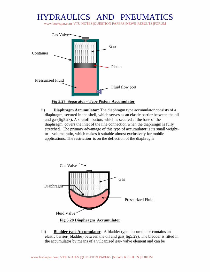
HYDRAULICS AND PNEUMATICS www.bookspar.com |VTU NOTES |QUESTION PAPERS |NEWS |RESULTS |FORUM
www.bookspar.com |VTU NOTES |QUESTION PAPERS |NEWS |RESULTS |FORUM
Gas Valve
Gas Container
Piston
Pressurized Fluid
Fluid flow port Fig 5.27 Separator - Type Piston Accumulator
ii) Diaphragm Accumulator: The diaphragm type accumulator consists of a diaphragm, secured in the shell, which serves as an elastic barrier between the oil and gas(fig5.28). A shutoff button, which is secured at the base of the diaphragm, covers the inlet of the line connection when the diaphragm is fully stretched. The primary advantage of this type of accumulator is its small weight- to – volume ratio, which makes it suitable almost exclusively for mobile applications. The restriction is on the deflection of the diaphragm
Gas Valve
Gas
Diaphragm
Pressurized Fluid
Fluid Valve
Fig 5.28 Diaphragm Accumulator
iii) Bladder type Accumulator: A bladder type- accumulator contains an elastic barrier( bladder) between the oil and gas( fig5.29). The bladder is fitted in the accumulator by means of a vulcanized gas- valve element and can be
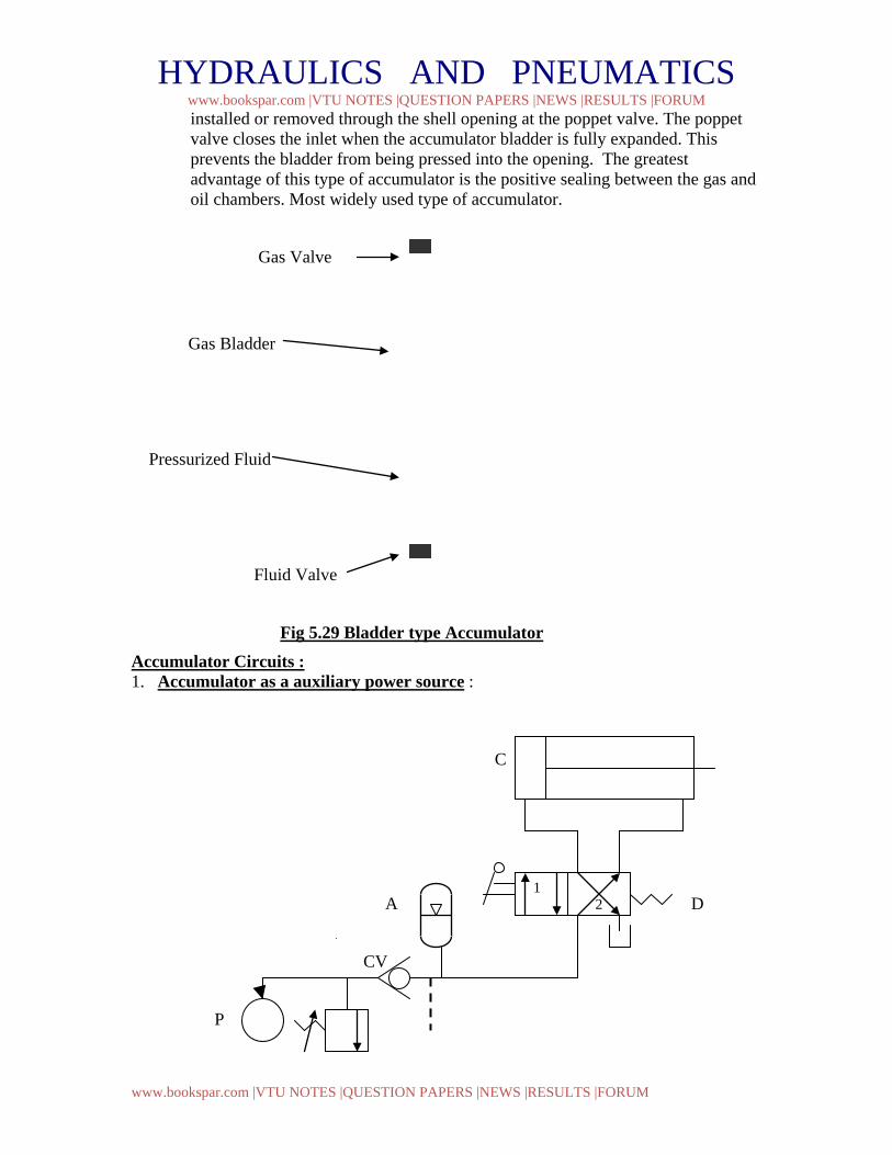
HYDRAULICS AND PNEUMATICS www.bookspar.com |VTU NOTES |QUESTION PAPERS |NEWS |RESULTS |FORUM
www.bookspar.com |VTU NOTES |QUESTION PAPERS |NEWS |RESULTS |FORUM
installed or removed through the shell opening at the poppet valve. The poppet valve closes the inlet when the accumulator bladder is fully expanded. This prevents the bladder from being pressed into the opening. The greatest advantage of this type of accumulator is the positive sealing between the gas and oil chambers. Most widely used type of accumulator.
Gas Valve
Gas Bladder
Pressurized Fluid
Fluid Valve
Fig 5.29 Bladder type Accumulator Accumulator Circuits : 1. Accumulator as a auxiliary power source :
C
A D
CV
P
1 2
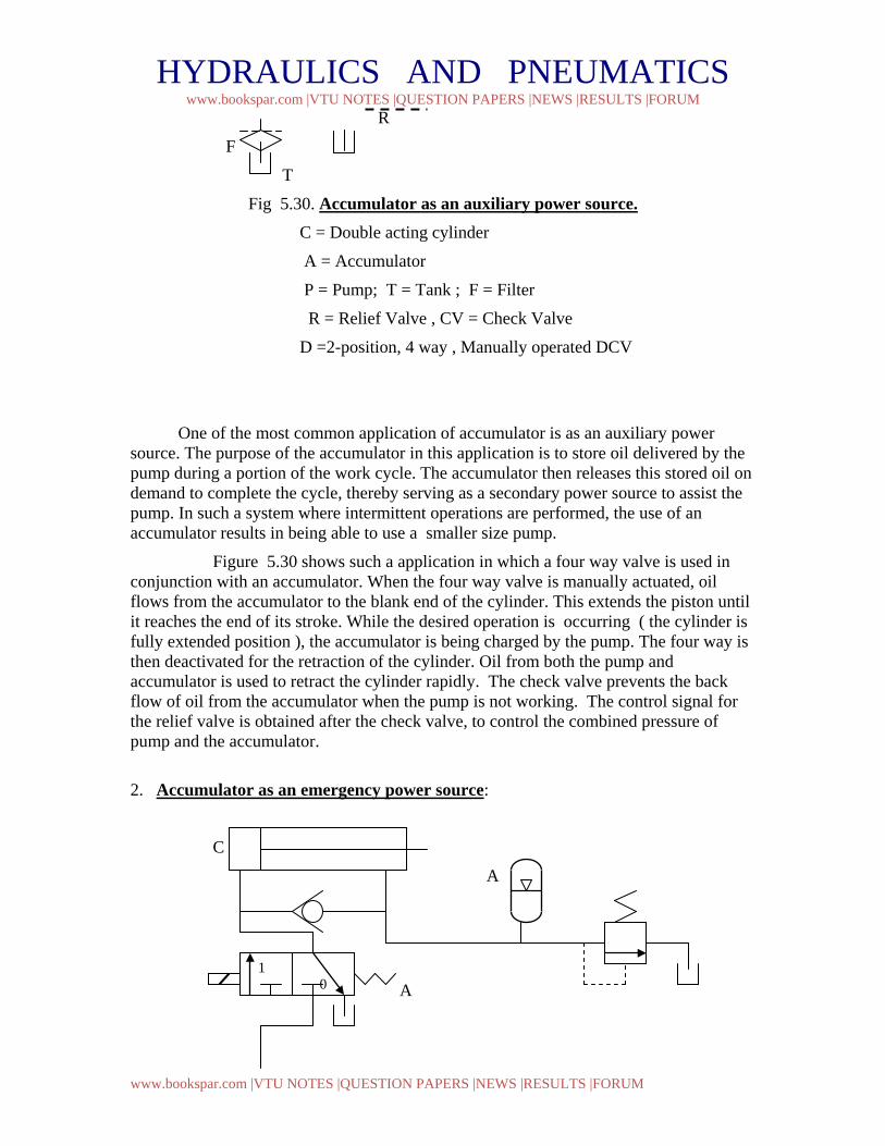
HYDRAULICS AND PNEUMATICS www.bookspar.com |VTU NOTES |QUESTION PAPERS |NEWS |RESULTS |FORUM
www.bookspar.com |VTU NOTES |QUESTION PAPERS |NEWS |RESULTS |FORUM
R
F
T
Fig 5.30. Accumulator as an auxiliary power source. C = Double acting cylinder
A = Accumulator
P = Pump; T = Tank ; F = Filter
R = Relief Valve , CV = Check Valve
D =2-position, 4 way , Manually operated DCV
One of the most common application of accumulator is as an auxiliary power source. The purpose of the accumulator in this application is to store oil delivered by the pump during a portion of the work cycle. The accumulator then releases this stored oil on demand to complete the cycle, thereby serving as a secondary power source to assist the pump. In such a system where intermittent operations are performed, the use of an accumulator results in being able to use a smaller size pump.
Figure 5.30 shows such a application in which a four way valve is used in conjunction with an accumulator. When the four way valve is manually actuated, oil flows from the accumulator to the blank end of the cylinder. This extends the piston until it reaches the end of its stroke. While the desired operation is occurring ( the cylinder is fully extended position ), the accumulator is being charged by the pump. The four way is then deactivated for the retraction of the cylinder. Oil from both the pump and accumulator is used to retract the cylinder rapidly. The check valve prevents the back flow of oil from the accumulator when the pump is not working. The control signal for the relief valve is obtained after the check valve, to control the combined pressure of pump and the accumulator.
2. Accumulator as an emergency power source:
C
A
A
1 0
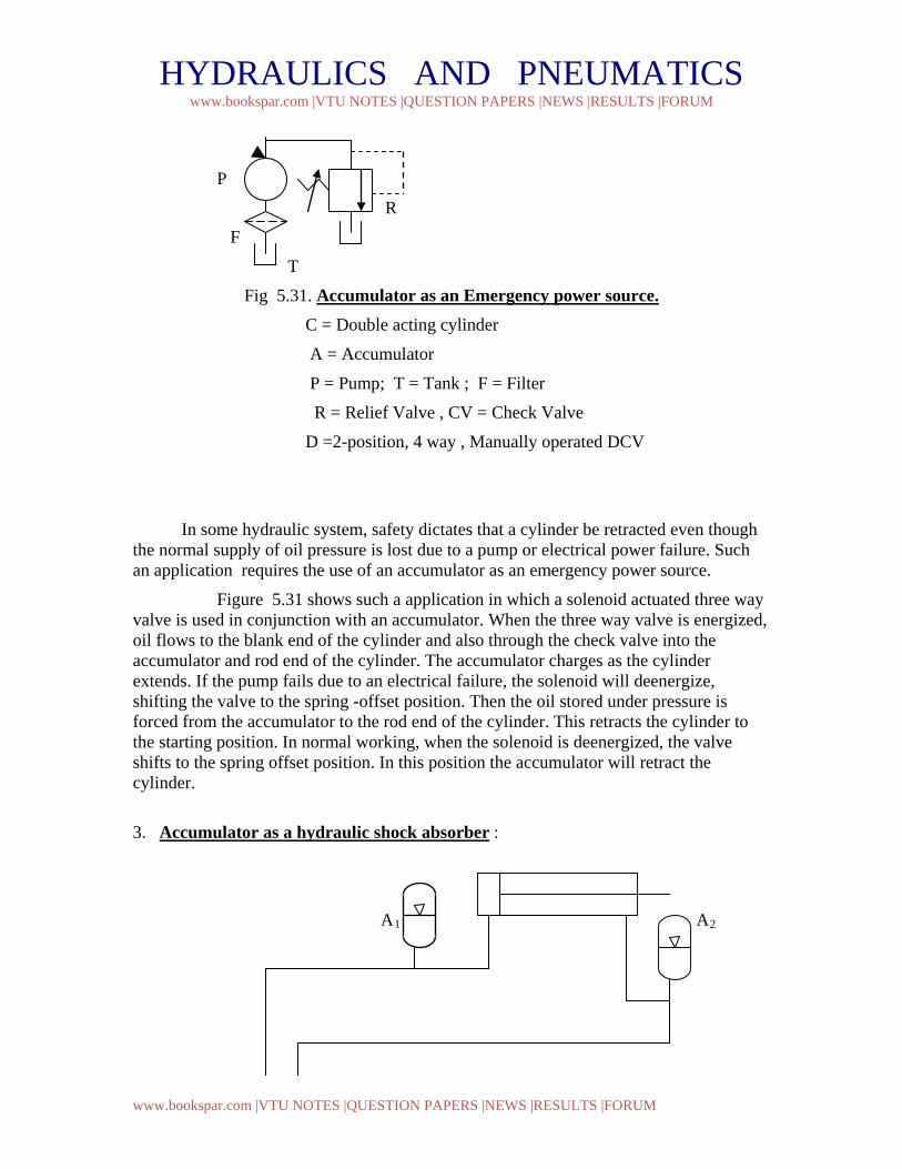
HYDRAULICS AND PNEUMATICS www.bookspar.com |VTU NOTES |QUESTION PAPERS |NEWS |RESULTS |FORUM
www.bookspar.com |VTU NOTES |QUESTION PAPERS |NEWS |RESULTS |FORUM
P
R
F
T
Fig 5.31. Accumulator as an Emergency power source. C = Double acting cylinder
A = Accumulator
P = Pump; T = Tank ; F = Filter
R = Relief Valve , CV = Check Valve
D =2-position, 4 way , Manually operated DCV
In some hydraulic system, safety dictates that a cylinder be retracted even though the normal supply of oil pressure is lost due to a pump or electrical power failure. Such an application requires the use of an accumulator as an emergency power source.
Figure 5.31 shows such a application in which a solenoid actuated three way valve is used in conjunction with an accumulator. When the three way valve is energized, oil flows to the blank end of the cylinder and also through the check valve into the accumulator and rod end of the cylinder. The accumulator charges as the cylinder extends. If the pump fails due to an electrical failure, the solenoid will deenergize, shifting the valve to the spring -offset position. Then the oil stored under pressure is forced from the accumulator to the rod end of the cylinder. This retracts the cylinder to the starting position. In normal working, when the solenoid is deenergized, the valve shifts to the spring offset position. In this position the accumulator will retract the cylinder.
3. Accumulator as a hydraulic shock absorber :
A1 A2
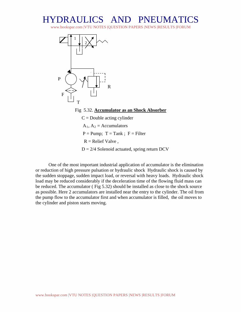
HYDRAULICS AND PNEUMATICS www.bookspar.com |VTU NOTES |QUESTION PAPERS |NEWS |RESULTS |FORUM
www.bookspar.com |VTU NOTES |QUESTION PAPERS |NEWS |RESULTS |FORUM
P
R
F
T
Fig 5.32. Accumulator as an Shock Absorber C = Double acting cylinder
A1, A2 = Accumulators
P = Pump; T = Tank ; F = Filter
R = Relief Valve ,
D = 2/4 Solenoid actuated, spring return DCV
One of the most important industrial application of accumulator is the elimination or reduction of high pressure pulsation or hydraulic shock Hydraulic shock is caused by the sudden stoppage, sudden impact load, or reversal with heavy loads. Hydraulic shock load may be reduced considerably if the deceleration time of the flowing fluid mass can be reduced. The accumulator ( Fig 5.32) should be installed as close to the shock source as possible. Here 2 accumulators are installed near the entry to the cylinder. The oil from the pump flow to the accumulator first and when accumulator is filled, the oil moves to the cylinder and piston starts moving.
1 2