Embed Size (px)
Citation preview
Hydraulic Circuit Design
M. S. Sham PrasadAsst. Professor
Dept. of I&P Engg.National Institute of Engg, Mysore
26/10/05Hydraulics & Pneumatics
Regenerative circuit :
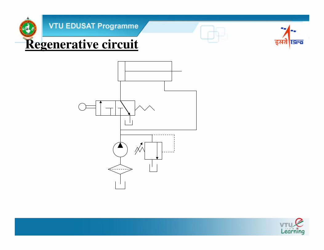
A Regenerative circuit is one in which pressurized fluid discharged from a component is returned to the system to reduce power requirements of the pump.
• Flow from the rod end (Qr) regenerates with the pump flow (QP) to provide a total flow rate (QT), which is greater than the pump flow rate to the blank end of the cylinder.
• The speed of extension is greater than that for a regular double-acting cylinder
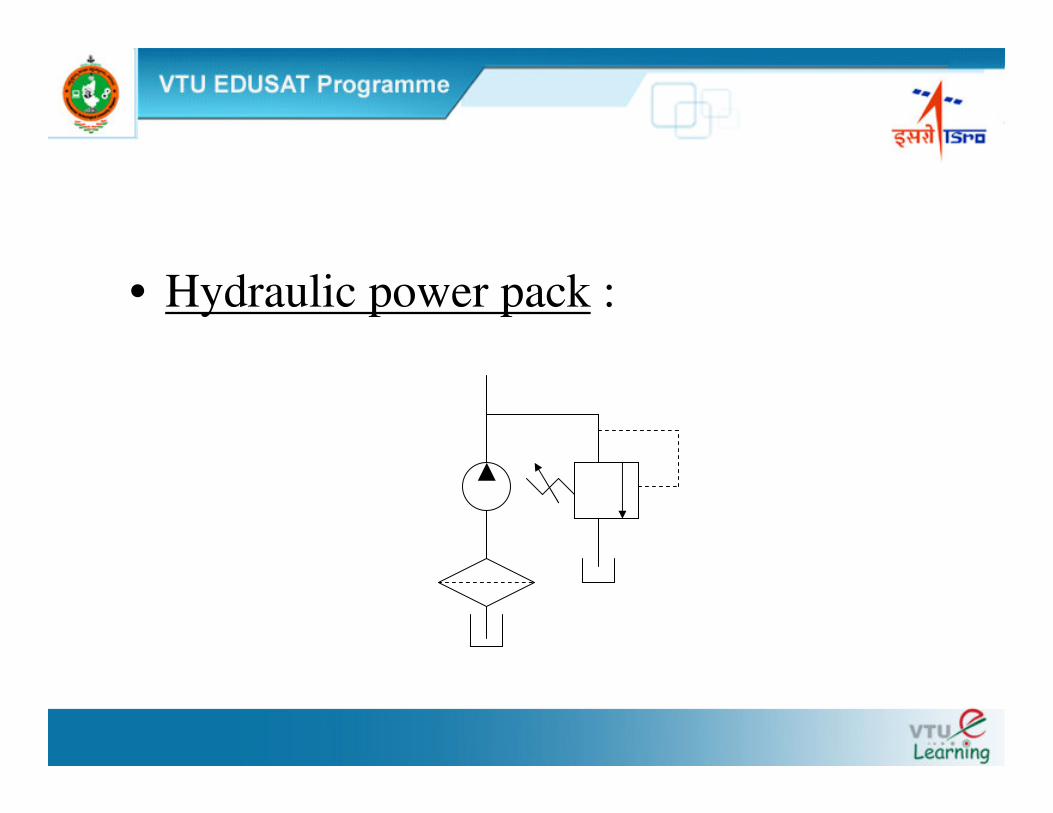
• Hydraulic power pack :
Regenerative circuit

Regenerative circuit
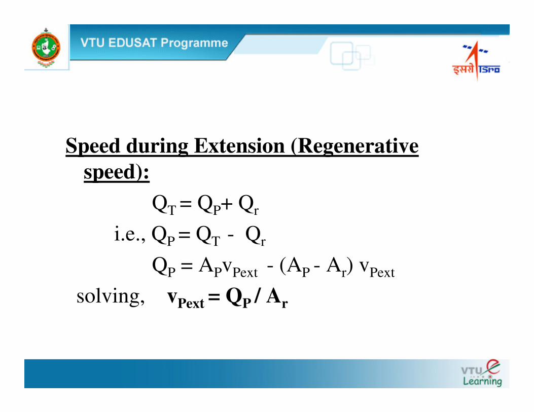
Speed during Extension (Regenerative speed):
QT = QP+ Qr
i.e., QP = QT - Qr
QP = APvPext - (AP - Ar) vPext
solving, vPext = QP / Ar
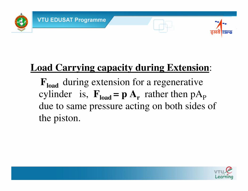
Load Carrying capacity during Extension: Fload during extension for a regenerative cylinder is, Fload = p Ar rather then pAPdue to same pressure acting on both sides of the piston.
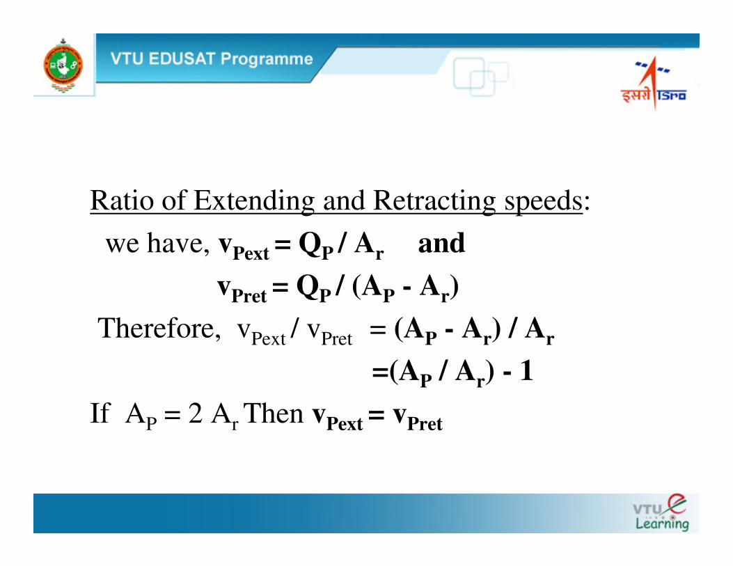
Ratio of Extending and Retracting speeds: we have, vPext = QP / Ar and
vPret = QP / (AP - Ar)Therefore, vPext / vPret = (AP - Ar) / Ar
=(AP / Ar) - 1 If AP = 2 Ar Then vPext = vPret
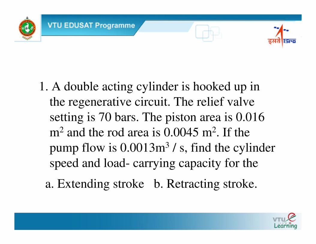
1. A double acting cylinder is hooked up in the regenerative circuit. The relief valve setting is 70 bars. The piston area is 0.016 m2 and the rod area is 0.0045 m2. If the pump flow is 0.0013m3 / s, find the cylinder speed and load- carrying capacity for the
a. Extending stroke b. Retracting stroke.
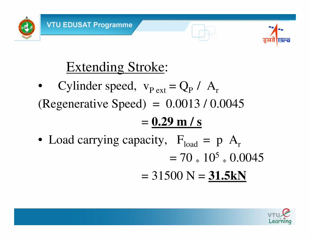
Extending Stroke:• Cylinder speed, vP ext = QP / Ar
(Regenerative Speed) = 0.0013 / 0.0045= 0.29 m / s
• Load carrying capacity, Fload = p Ar
= 70 * 105* 0.0045
= 31500 N = 31.5kN
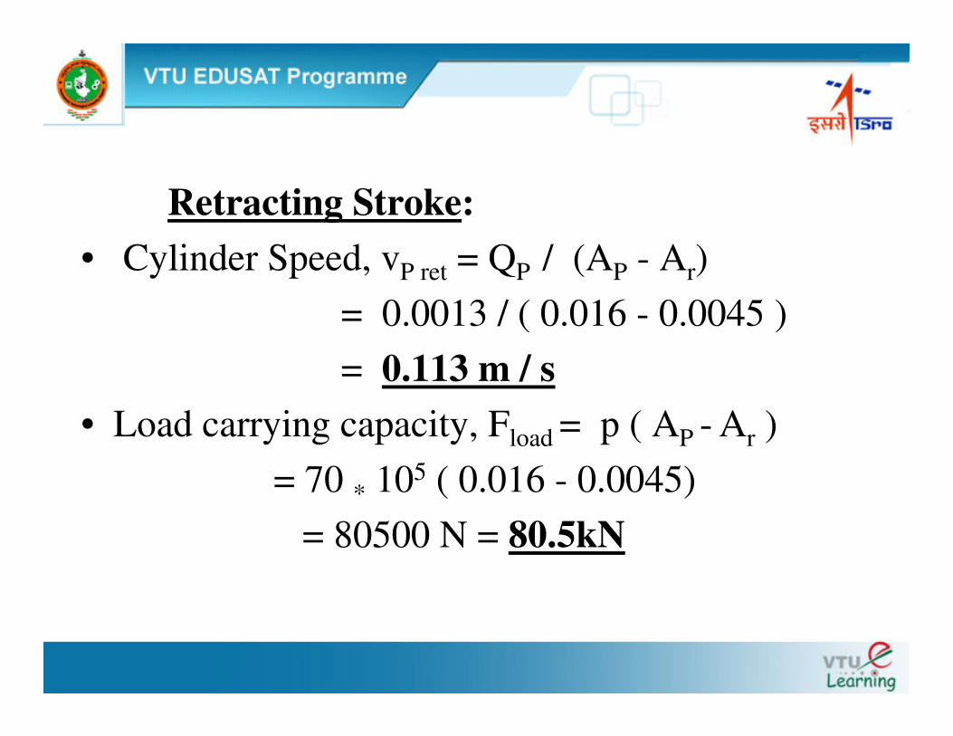
Retracting Stroke:• Cylinder Speed, vP ret = QP / (AP - Ar)
= 0.0013 / ( 0.016 - 0.0045 ) = 0.113 m / s
• Load carrying capacity, Fload = p ( AP - Ar ) = 70 * 105 ( 0.016 - 0.0045)
= 80500 N = 80.5kN
2. A double acting cylinder is hooked up in the regenerative circuit. The relief valve setting is 100 bars. The piston area is twice the rod area. If the pump flow is 0.0016m3 / s, and regenerative speed is 0.25 m/s, find the piston area and load-carrying capacity for the a. Extending stroke b. Retracting stroke
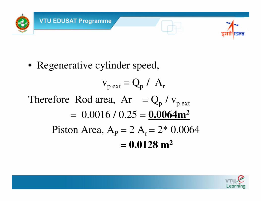
• Regenerative cylinder speed,
vp ext = Qp / Ar
Therefore Rod area, Ar = Qp / vp ext
= 0.0016 / 0.25 = 0.0064m2
Piston Area, AP = 2 Ar = 2* 0.0064 = 0.0128 m2
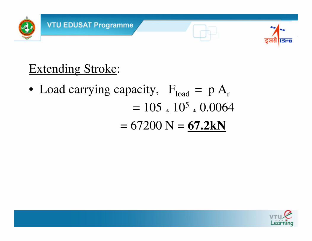
Extending Stroke:
• Load carrying capacity, Fload = p Ar
= 105 * 105* 0.0064
= 67200 N = 67.2kN
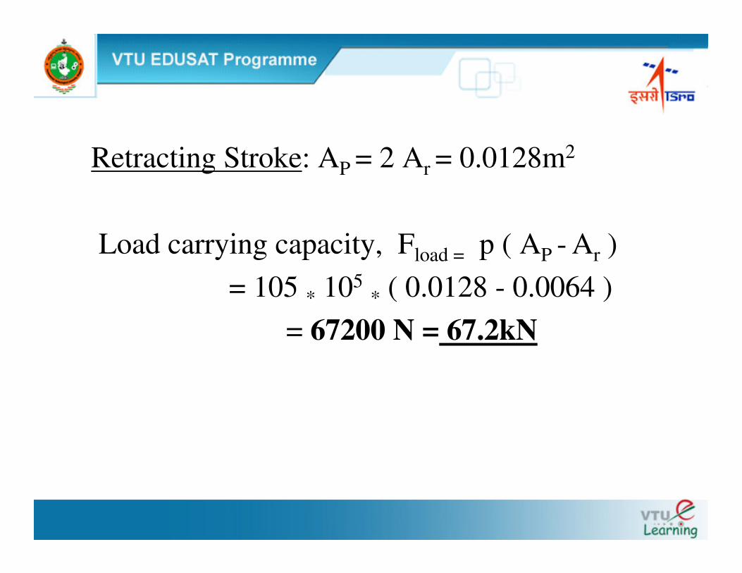
Retracting Stroke: AP = 2 Ar = 0.0128m2
Load carrying capacity, Fload = p ( AP - Ar )= 105 * 105
* ( 0.0128 - 0.0064 )= 67200 N = 67.2kN
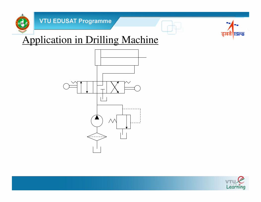
Application in Drilling Machine
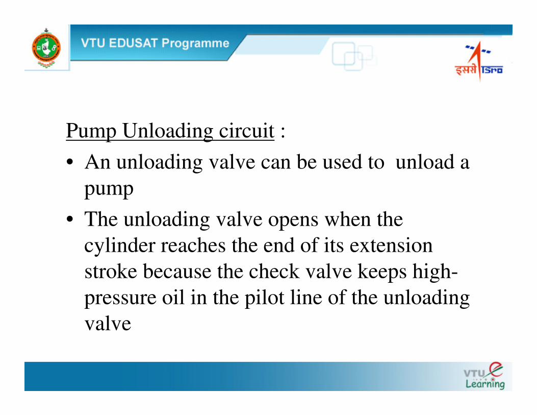
Pump Unloading circuit : • An unloading valve can be used to unload a
pump• The unloading valve opens when the
cylinder reaches the end of its extension stroke because the check valve keeps high-pressure oil in the pilot line of the unloading valve
The control signal for unloading valve is remote and obtained after the check valve whereas in Relief valve it is inside the valve.
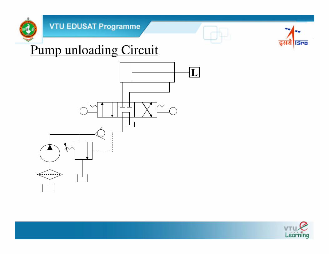
Pump unloading Circuit
L
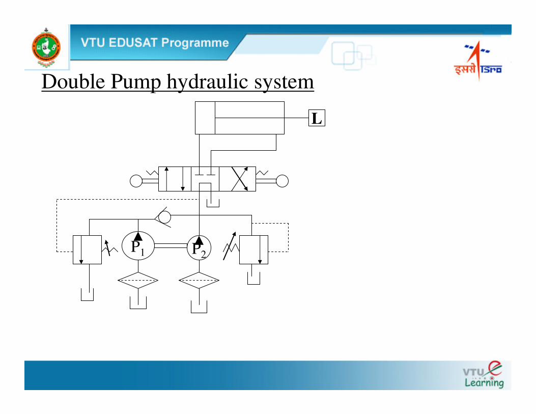
Double Pump Hydraulic system ( Hi – Lo circuit )
• Two pumps, one high-pressure, low-flow pump and the other low-pressure, high-flow pump.
• Application in a punch press in which the hydraulic ram must extend rapidly over a large distance with very low pressure but high flow requirements.
• During the short motion portion when the punching operation occurs, the pressure requirements are high due to the punching load.
• Since the cylinder travel is small during the punching operation, the flow-rate requirements are also low.
• The circuit eliminates the necessity of having a very expensive high-pressure, high-flow pump.
• When the punching operation begins, the increased pressure opens the unloading valve to unload the low-pressure pump
• The relief valve protect the high-pressure pump from overpressure at the end of the cylinder stroke.
The check valve protects the low pressure pump:
• From high pressure, which occurs during the punching operation.
• At the ends of the cylinder stroke,
• When the DCV is in its spring-centered mode.
Double Pump hydraulic system
P2
L
P1
Application of CounterBalance valve
• Used to keep a vertical cylinder in the upward position while the pump is idling.
• Lower the load gradually.
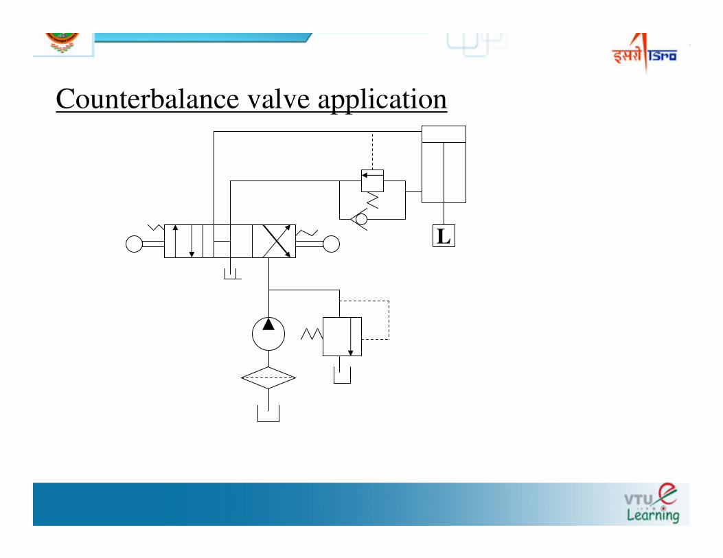
Counterbalance valve application
L
Cylinder Sequencing circuit:• Two cylinder(C1 & C2 ) have sequence of
operation.• Operation sequence is :
C1 + C2+ C2- C1 -• + is Extension of piston• - is Retraction of piston
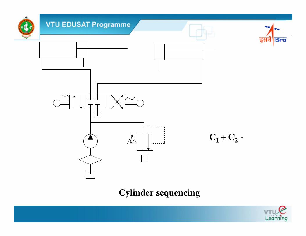
C1 + C2 -
Cylinder sequencing
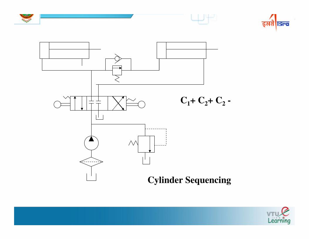
C1+ C2+ C2 -
Cylinder Sequencing
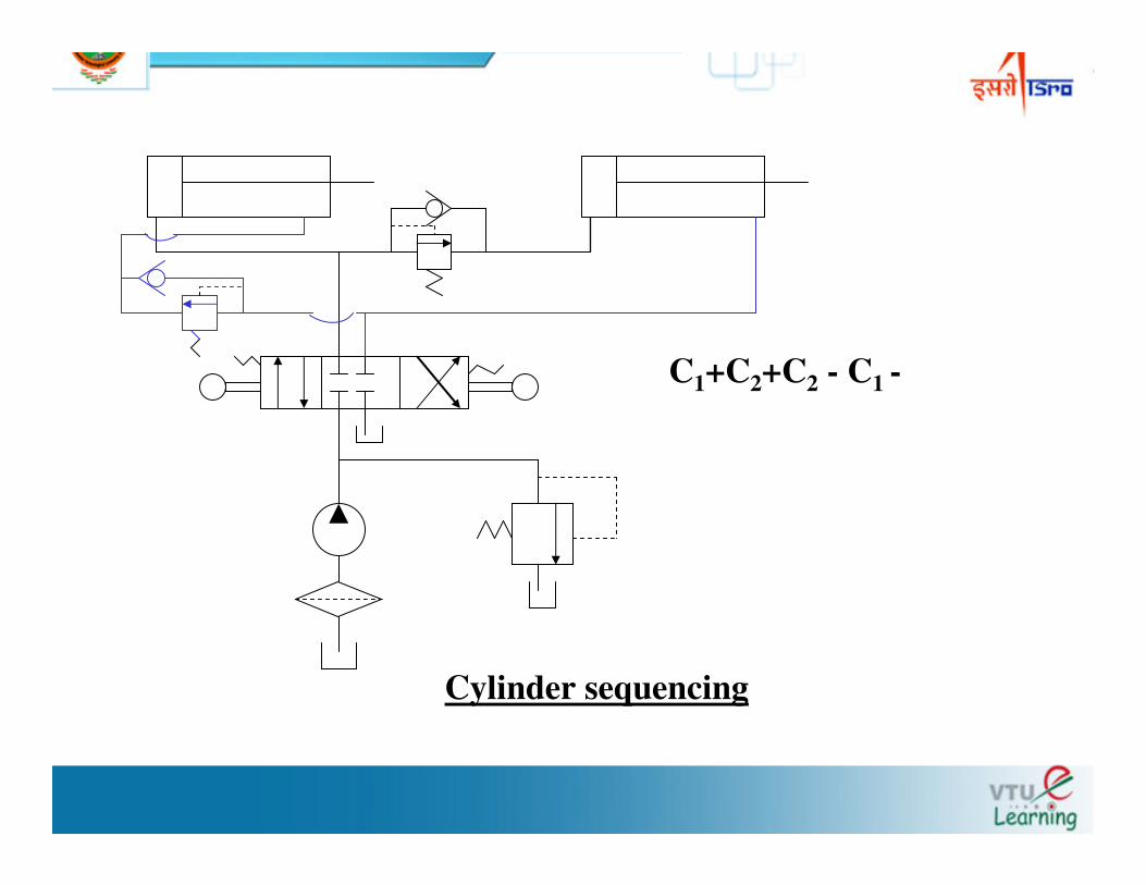
C1+C2+C2 - C1 -
Cylinder sequencing
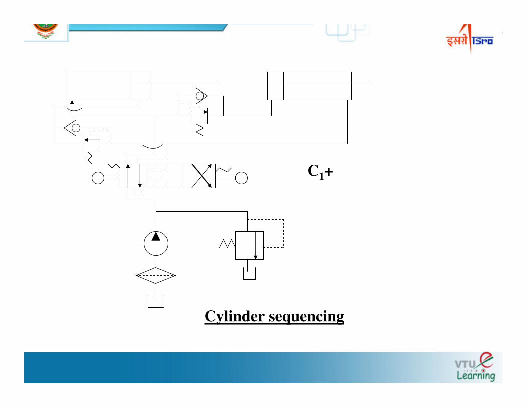
C1+
Cylinder sequencing
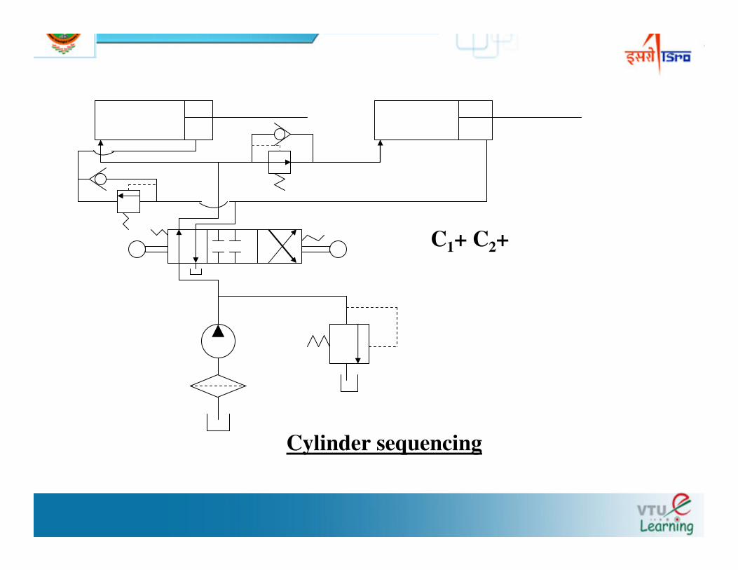
C1+ C2+
Cylinder sequencing
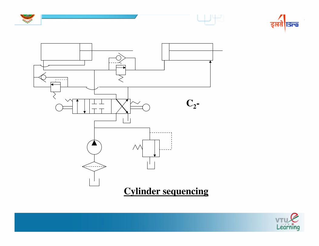
C2-
Cylinder sequencing
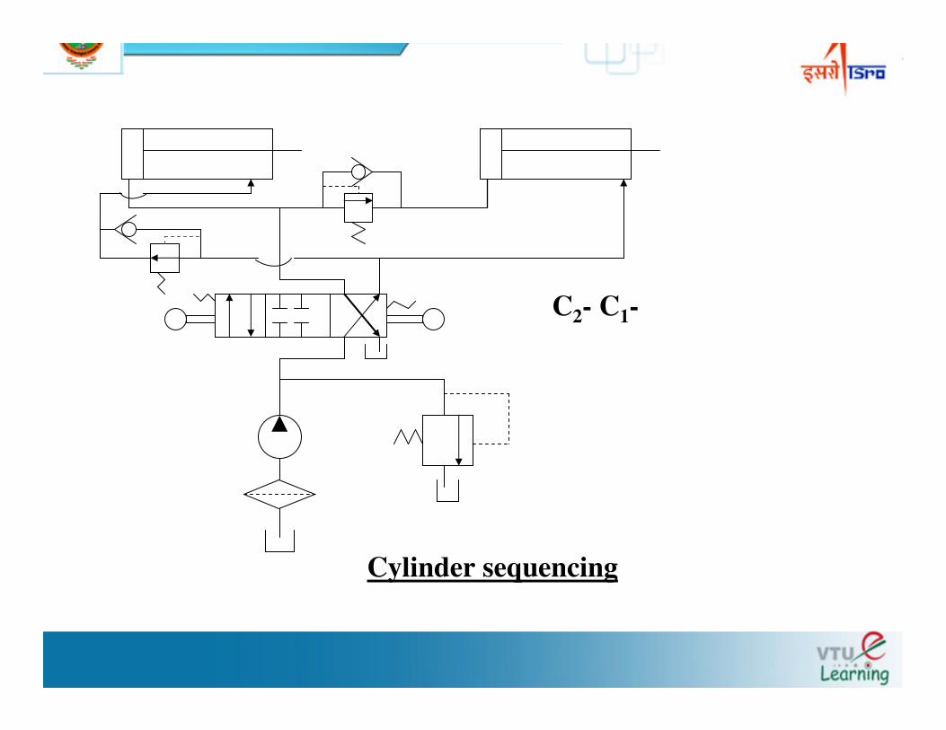
C2- C1-
Cylinder sequencing
Problem : Design a sequencing circuit for operating two cylinders in sequence. The sequence of operations are C1+C2+C1 - C2 -
Solution: Observe the cylinder 1 is extended and retracted first
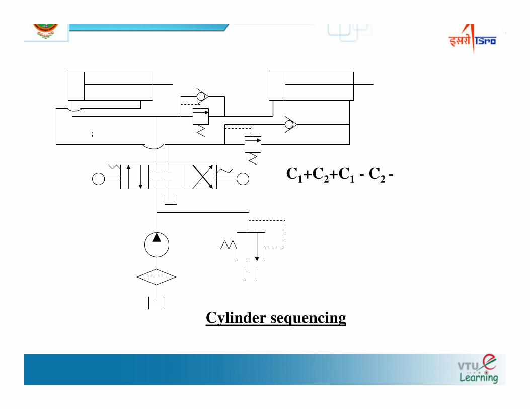
C1+C2+C1 - C2 -
Cylinder sequencing