Embed Size (px)
Citation preview
How to operate the sound desk:
!!!1. Turn on the first three power point switches located at underneath the
cords for the lights. 2. Turn on the mixer. The power switch is located at the top right on the
back of the mixer. The mixer is always first on and last off. 3. Ensure both EQ’s are on (the 2nd one is always on). Press and hold the
power button on the top one if it is not on. 4. Turn on both amplifiers. Turn the 3/4. !!!
Page ! of !1 4
VIEW
VIEW
VIEWVIEWVIEWVIEWVIEWVIEW
VIEW
VIEW
VIEW
– 5
5
0
–10
10
– 20
– 30
– 40
– 50
– 60
– 00
– 5
5
0
–10
10
– 20
– 30
– 40
– 50
– 60
– 00
– 5
5
0
–10
10
– 20
– 30
– 40
– 50
– 60
– 00
– 6
(1) (3)
(4) (5)(2)
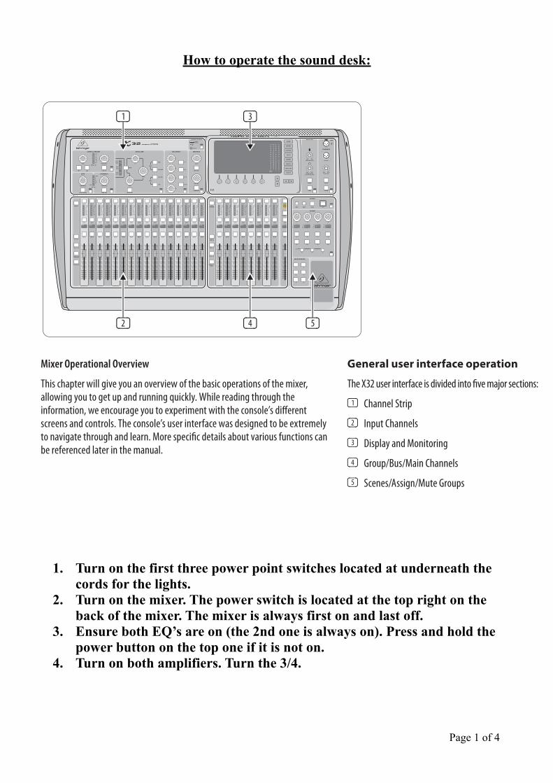
Mixer Operational Overview
This chapter will give you an overview of the basic operations of the mixer, allowing you to get up and running quickly. While reading through the information, we encourage you to experiment with the console’s different screens and controls. The console’s user interface was designed to be extremely to navigate through and learn. More specific details about various functions can be referenced later in the manual.
General user interface operation
The X32 user interface is divided into five major sections:
(1) Channel Strip
(2) Input Channels
(3) Display and Monitoring
(4) Group/Bus/Main Channels
(5) Scenes/Assign/Mute Groups
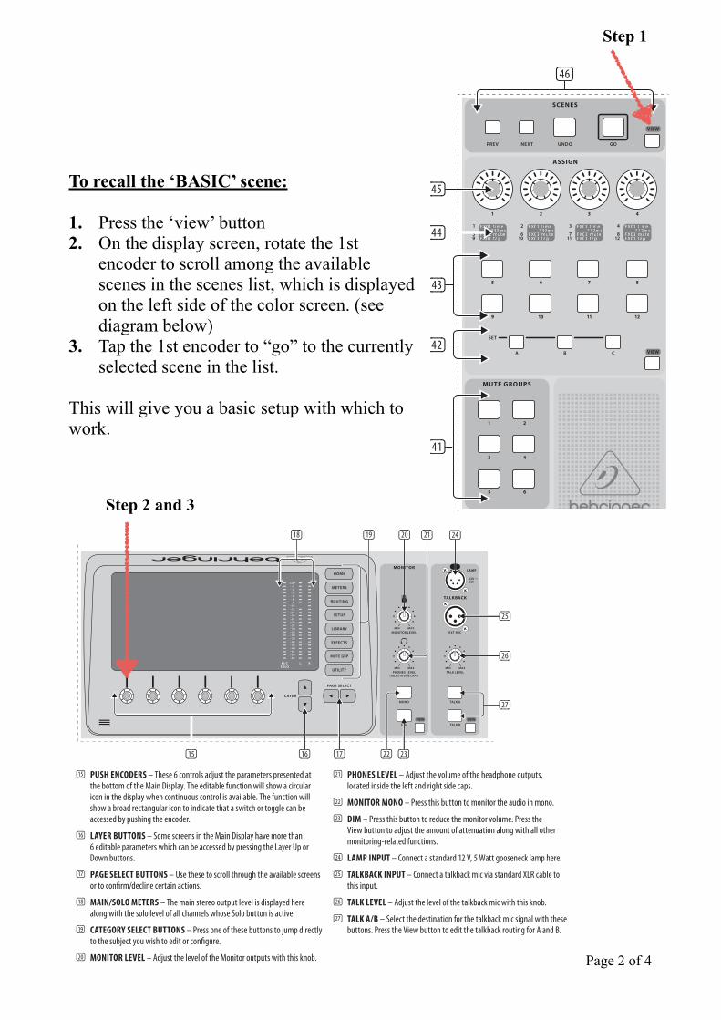
!!!!!To recall the ‘BASIC’ scene: !1. Press the ‘view’ button 2. On the display screen, rotate the 1st
encoder to scroll among the available scenes in the scenes list, which is displayed on the left side of the color screen. (see diagram below)
3. Tap the 1st encoder to “go” to the currently selected scene in the list. !
This will give you a basic setup with which to work.
!!!!!!!!!!!!!!!!!!!Page ! of !2 4
VIEW
VIEW
(45)
(44)
(43)
(42)
(41)
(46)
Step 1
14 X32 DIGITAL MIXER Preliminary User Manual
2.3 Display and Monitoring
VIEWVIEW
(16) (23)
(20)
(26)
(25)
(17) (22)
(27)
(21)(19)(18)
(15)
(24)
(15) PUSH ENCODERS – These 6 controls adjust the parameters presented at the bottom of the Main Display. The editable function will show a circular icon in the display when continuous control is available. The function will show a broad rectangular icon to indicate that a switch or toggle can be accessed by pushing the encoder.
(16) LAYER BUTTONS – Some screens in the Main Display have more than 6 editable parameters which can be accessed by pressing the Layer Up or Down buttons.
(17) PAGE SELECT BUTTONS – Use these to scroll through the available screens or to confirm/decline certain actions.
(18) MAIN/SOLO METERS – The main stereo output level is displayed here along with the solo level of all channels whose Solo button is active.
(19) CATEGORY SELECT BUTTONS – Press one of these buttons to jump directly to the subject you wish to edit or configure.
(20) MONITOR LEVEL – Adjust the level of the Monitor outputs with this knob.
(21) PHONES LEVEL – Adjust the volume of the headphone outputs, located inside the left and right side caps.
(22) MONITOR MONO – Press this button to monitor the audio in mono.
(23) DIM – Press this button to reduce the monitor volume. Press the View button to adjust the amount of attenuation along with all other monitoring-related functions.
(24) LAMP INPUT – Connect a standard 12 V, 5 Watt gooseneck lamp here.
(25) TALKBACK INPUT – Connect a talkback mic via standard XLR cable to this input.
(26) TALK LEVEL – Adjust the level of the talkback mic with this knob.
(27) TALK A/B – Select the destination for the talkback mic signal with these buttons. Press the View button to edit the talkback routing for A and B.
Step 2 and 3
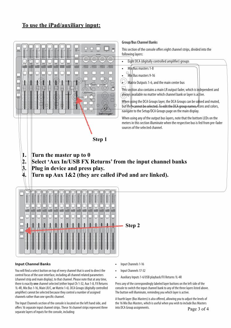
To use the iPad/auxiliary input:
!1. Turn the master up to 0 2. Select ‘Aux In/USB FX Returns’ from the input channel banks 3. Plug in device and press play. 4. Turn up Aux 1&2 (they are called iPod and are linked).
Page ! of !3 4
Group/Bus Channel Banks
This section of the console offers eight channel strips, divided into the following layers:
Eight DCA (digitally controlled amplifier) groups
Mix Bus masters 1-8
Mix Bus masters 9-16
Matrix Outputs 1-6, and the main center bus
This section also contains a main LR output fader, which is independent and always available no matter which channel bank or layer is active.
When using the DCA Groups layer, the DCA Groups can be soloed and muted, but they cannot be selected. To edit the DCA group names, icons and colors, navigate to the Setup/DCA Groups page on the main display.
When using any of the output bus layers, note that the bottom LEDs on the meters in this section illuminate when the respective bus is fed from pre-fader sources of the selected channel.
VIEW
VIEW
– 6
Step 1
6 X32 DIGITAL MIXER Preliminary User Manual
– 5
5
0
–10
10
– 20
– 30
– 40
– 50
– 60
– 00
– 5
5
0
–10
10
– 20
– 30
– 40
– 50
– 60
– 00
– 5
5
0
–10
10
– 20
– 30
– 40
– 50
– 60
– 00
Input Channel Banks
You will find a select button on top of every channel that is used to direct the control focus of the user interface, including all channel related parameters (channel strip and main display), to that channel. Please note that at any time, there is exactly one channel selected (either Input Ch 1-32, Aux 1-8, FX Returns 1L-4R, Mix Bus 1-16, Main LR/C, or Matrix 1-6). DCA Groups (digitally controlled amplifier) cannot be selected because they control a number of assigned channels rather than one specific channel.
The Input Channels section of the console is located on the left hand side, and offers 16 separate input channel strips. These 16 channel strips represent three separate layers of inputs for the console, including:
Input Channels 1-16
Input Channels 17-32
Auxiliary Inputs 1-6/USB playback/FX Returns 1L-4R
Press any of the correspondingly labeled layer buttons on the left side of the console to switch the input channel bank to any of the three layers listed above. The button will illuminate, reminding you which layer is active.
A fourth layer (Bus Masters) is also offered, allowing you to adjust the levels of the 16 Mix Bus Masters, which is useful when you wish to include Bus Masters into DCA Group assignments.
VIEWVIEWVIEWVIEW
VIEW
VIEW
VIEW
Channel Strip
The X32’s channel strip offers dedicated controls for the most important processing parameters of the currently selected channel. To adjust controls for a given channel strip, simply press the Select button on the desired input or output channel.
Certain sections of the channel strip (such as the low cut filter, noise gate, EQ and compressor) contain a respectively labeled button that can be pressed to switch the specific effect on and off. The button illuminates to show the effect is active, and goes dark when bypassed.
Within the channel strip, the rotary control knobs are surrounded by an amber LED collar that indicates the parameter’s value. Whenever this backlit knob is turned off, it indicates that this specific control/parameter is not available for the selected channel type. For example, if an output bus is currently selected,
the LED collar and the gain knob are turned off, because there is no input gain to be controlled on an output bus.
The channel strip consists of the following sub-sections:
Config/Preamp
Gate, Dynamics
Equalizer
Bus Sends, Main Bus
Each of these subsections correspond to the processing steps of the currently selected channel, and they each have their own View button that, when pressed, switches the Main Display to a page displaying all related parameters for that subsection.
Step 2
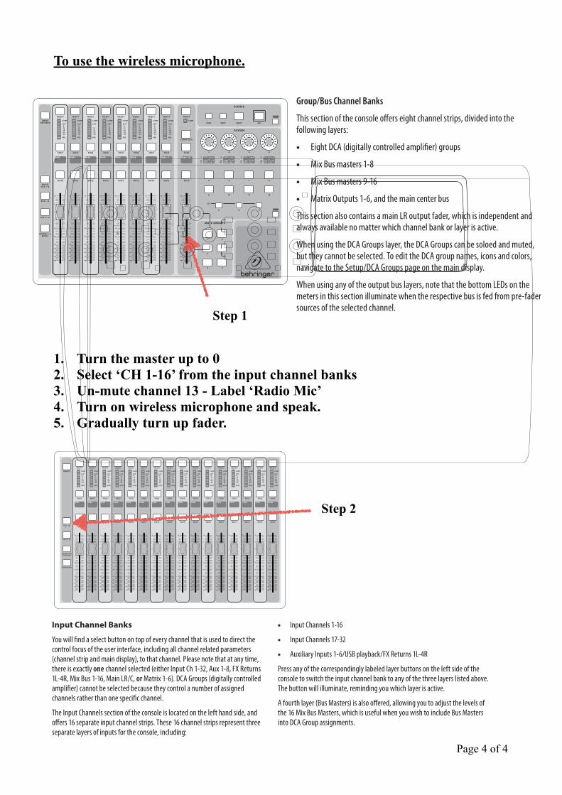
To use the wireless microphone.
1. Turn the master up to 0 2. Select ‘CH 1-16’ from the input channel banks 3. Un-mute channel 13 - Label ‘Radio Mic’ 4. Turn on wireless microphone and speak. 5. Gradually turn up fader.
Page ! of !4 4
Group/Bus Channel Banks
This section of the console offers eight channel strips, divided into the following layers:
Eight DCA (digitally controlled amplifier) groups
Mix Bus masters 1-8
Mix Bus masters 9-16
Matrix Outputs 1-6, and the main center bus
This section also contains a main LR output fader, which is independent and always available no matter which channel bank or layer is active.
When using the DCA Groups layer, the DCA Groups can be soloed and muted, but they cannot be selected. To edit the DCA group names, icons and colors, navigate to the Setup/DCA Groups page on the main display.
When using any of the output bus layers, note that the bottom LEDs on the meters in this section illuminate when the respective bus is fed from pre-fader sources of the selected channel.
VIEW
VIEW
– 6
Step 1
6 X32 DIGITAL MIXER Preliminary User Manual
– 5
5
0
–10
10
– 20
– 30
– 40
– 50
– 60
– 00
– 5
5
0
–10
10
– 20
– 30
– 40
– 50
– 60
– 00
– 5
5
0
–10
10
– 20
– 30
– 40
– 50
– 60
– 00
Input Channel Banks
You will find a select button on top of every channel that is used to direct the control focus of the user interface, including all channel related parameters (channel strip and main display), to that channel. Please note that at any time, there is exactly one channel selected (either Input Ch 1-32, Aux 1-8, FX Returns 1L-4R, Mix Bus 1-16, Main LR/C, or Matrix 1-6). DCA Groups (digitally controlled amplifier) cannot be selected because they control a number of assigned channels rather than one specific channel.
The Input Channels section of the console is located on the left hand side, and offers 16 separate input channel strips. These 16 channel strips represent three separate layers of inputs for the console, including:
Input Channels 1-16
Input Channels 17-32
Auxiliary Inputs 1-6/USB playback/FX Returns 1L-4R
Press any of the correspondingly labeled layer buttons on the left side of the console to switch the input channel bank to any of the three layers listed above. The button will illuminate, reminding you which layer is active.
A fourth layer (Bus Masters) is also offered, allowing you to adjust the levels of the 16 Mix Bus Masters, which is useful when you wish to include Bus Masters into DCA Group assignments.
VIEWVIEWVIEWVIEW
VIEW
VIEW
VIEW
Channel Strip
The X32’s channel strip offers dedicated controls for the most important processing parameters of the currently selected channel. To adjust controls for a given channel strip, simply press the Select button on the desired input or output channel.
Certain sections of the channel strip (such as the low cut filter, noise gate, EQ and compressor) contain a respectively labeled button that can be pressed to switch the specific effect on and off. The button illuminates to show the effect is active, and goes dark when bypassed.
Within the channel strip, the rotary control knobs are surrounded by an amber LED collar that indicates the parameter’s value. Whenever this backlit knob is turned off, it indicates that this specific control/parameter is not available for the selected channel type. For example, if an output bus is currently selected,
the LED collar and the gain knob are turned off, because there is no input gain to be controlled on an output bus.
The channel strip consists of the following sub-sections:
Config/Preamp
Gate, Dynamics
Equalizer
Bus Sends, Main Bus
Each of these subsections correspond to the processing steps of the currently selected channel, and they each have their own View button that, when pressed, switches the Main Display to a page displaying all related parameters for that subsection.
Step 2

![High Voltage Modular Training Set HV 9000 - Terco [Swedish] · 2009-12-14 · HV 9103 Control Desk This control desk is used to control and operate high voltage AC/DC/Impulse test](https://img.pdfslide.us/doc/110x75/5e933ba3423afc22b00e6af5/high-voltage-modular-training-set-hv-9000-terco-swedish-2009-12-14-hv-9103.jpg)