Embed Size (px)
Citation preview
CONFIDENTIAL
LOW FREQUENCY DETECTORS OF UNDERWATER SOUND
5. N. HEAPS
Technical Report No. 680(00)-7 April 20, 195U
The research reported in this document was done under ONR Contract No. 680(00) between the Office of Naval Research tnd the Magnolia Petroleum Company.
Magnolia Petroleum Company Field Research Laboratories
Dallas, Texas
Report by Approved for Distribution
54AA 3828F

THIS REPORT HAS BEEN DELIMITED
AND CLEARED FOR PUBLIC RELEASE
JNDER DOD DIRECTIVE 5200,20 AND
•\0 RESTRICTIONS ARE IMPOSED UPON
ITS USE AND DISCLOSURE,
DISTRIBUTION STATEMENT A
APPROVED FOR PUBLIC RELEASE;
DISTRIBUTION UNLIMITED,

NOTICE: THIS DOCUMENT CONTAINS INFORMATION AFFECTING THE
NATIONAL DEFENSE OF THE UNITED SI ATES WITHIN THE MEANING
OF THE ESPIONAGE LAWS, TITLE 18, U.S.C., SECTIONS 793 and 794.
THE TRANSMISSION OR THE REVELATION OF ITS CONTENTS IN
ANY MANNER TO AN UNAUTHORIZED PERSON IS PROHIBITED BY LAW.

CONFIDENTIAL
ABSTRACT
Under contract Nonr 680(00), the Field Research Laboratories of
the Magnolia Petroleum uomp&ny has designed and constructed a directional
indicator for underwater sound and an acoustic impedance meter. Both
instruments required acoustic pressure and velocity sensing detectors for
frequencies between 20 and £00 cycles per second. The pressure detector
employs a barium titanate crystal cylinder as a sensitive element and
represents only a slight modification of the usual hydrophone design.
The velocity detector employs a goophone of a type used in geophysical
prospecting as a sensitive element. In this report velocity detector
design criteria are discussed and proper methods are mentioned for success-
ful detector application to waterborne sound problems. This detector is
new in the field of acoustics and has several attractive features.
CONFIDENTIAL
'
I
CONFIDENTIAL
OF OMfiEBWATBl 55M5
TABLE OF CONTENTS
Page
Ts INTRODUCTION 1
II. GENERAL 3
III. DETECTOR DESIGN CRITERIA 7
17. MOUNTINO AND EXTRANEOUS INFLUENCES 10
V. RESULTS 12
VI. CONCLUSION 1$
REFERENCES 16
APPENDIX 17
Appendix Table of Contents 18
CONFIDENTIAL

CONFIDENTIAL
LOW FREQUENCY DETECTORS OF UNDHlWATSt SOlHS
I. INTRODUCTION
The Field Research Laboratories of the Magnolia Petroleum Company,
under Contract Nonr 680(00), has developed two types of underwater sound
instruments which exploit the low audio frequencies. The first to be
completed was S '••issive intensity •.eter which gives the direction of
arrival of underwater sound. This equipment has been described in pre-
vious reports, and has been sea tested for applications in both transient
and steady state sound fields/ *°' The second instrument was a bottom
impedance meter which has been given only preliminary operational tests.
Both pieces of equipment operate by an appropriate correlation of acoustic
pressure and velocity signals.
Unique detectors have been constructed to provide these signals,
| and their development constitutes a completed phase of the project. \
The pressure sensitive detectors represent a modification of the 3A
hydrophone design to permit operation at low frequency. The velocity
detectors incorporate goophones as the responsive element. More detail
has been considered in adapting geophones to acousoic problems because
results have been obtained which supplement those of other investigators.
(11,12) in au recent acoustics work with geophones they were placed
in contact with the se& bottom. Substantially contrasting behavior has
been obtained by means of good water coupling to the geophones and good
isolation from the bottom.
CONFIDENTIAL

!
CONFIDENTIAL
-2-
Spe-iirit; veiuciuy liewciurB are described and t,heir design criteria
discussed, but their characteristics should make them attractive in other
types of acoustic equipment. In any case, it is especially recommended
aa a small,, sturdy, cheap substitute for preasure gradient detector*.
It is extremely sensitive to velocity (the equivalent of pressure gradient)
over a band of frequencies at the low end of the spectrum. It should,
of course, be used only when the factors affecting its operation, as
pointed out herein, are properly considered. The pickups to be described
were required to have flat response from 20 to 500 cycles with high and
stable sensitivity. They were to be rugged, small, and light weight for
portable operation from either small craft or heavy vessels. A major
feature achieved in the Magnolia prototype equipment design is the use
of long-wave sound for acoustic directivity without large, bulky, or
heavy arrays of detectors, or complicated electrical or mechanical scanning
systems.
CONFIDENTIAL
;7_ "• IVf

CONFIDENTIAL
-3-
li. GENERAL
A frequency band of 20 to !>00 cycles per second was selected as
a deeirable band for operation of the sonic bearing indicator and the
iatpedance weter. In this band, the attenuation of undersea sound is
low, and sound generation by ocean going vessels is high.^1. At all
frequencies in this band the detectors were 3-Tali in comparison to the
wave length of sound. Velocity sensitive geophones, or seismometers,
for this frequency band are conventional, but their use under water is
unusual. Pieio-elsctric pressure detectors in water are conventional,
buw -heir use in this frequency band is new. Both velocity and pressure
sensitive types of pickups are necessary ports of the prototype equip-
ment. Since suitable detectors are commercially unavailable, titeir de-
sign and construction baofede a distinct phase of the project.
Tha construction of special pressure deteciors for our application
appeared to be advisable. No extensive investigation of all available
pressure sensitive detectors was conducted, but type A-3 hydrophones,
which were available and appeared to be the most suitable, were tested.
The signal-to-noise ratio was poor throughout the low frequency band;
however, these hydrophone:; v^rs intended for use at much higner frequency.
?!ese=»electric type pressure detectors for geophysical use nave been re-
ported and might have been tasted but exact i deifications of any avail-
able units have not been publicised. Satisfactory detectors representing
variations of tne typical hydrophoiiu doslgn -s:"i specially constructed
for our apparatus.
CONFIDENTIAL
5
CONFIDENTIAL
An acoustic velocity signal value may be determined from the
pressure gradient by using only pressure detector^ but. this method is
known to have low sensitivity and would have required very large spacing
between detectors in low frequency application. It was presumed that
detectors could be constructed which would be more suitable.
Oecphones ordinarily employed in seismic prospecting are normally
used on land or on the sea bottom as velocity sensitive pickups. Their
use in underwater prospecting is a comparatively recent trend, and under-
water models commercially available are considered unproven in other
acoustic applications. The high sensitivity throughout the low frequencies
indicated that suitable acoustic detectors could be constructed incorporating
geophcr.se as the sensitive element. This type of deteotcr has been used »
in some underwater sound investigations but geophysical seismometers have
(11) not found favor in underwater acoustics work. Most tests have employed
these units in their normal manner ~ vertically sensitive and acoustically
coupled to the sea bottom. The British have been most active in this
fieldv12' but have reported only limited success.
The geophone* used in the construction of underwater pickups are
commercially available/^) and no effort has been made to build them
under the Magnolia contract. Their construction is similar to that of
a permanent magnet dynamic loud speaker with no cone. Some detail may
(2 3) be found on geophones in literature on vibrographs or seismometers. '
The mass of the geophone's "voice coil", and the stiffness of the coil
suspension comprise & damped mechanical oscillator with one degree
CONFIDENTIAL

,
CONFIDENTIAL
-5-
of freedom. Normal geophone operation occurs at sound frequencies above
that of resonance of this mechanical system. The shock mounted coil
remains stationary, and the magnet and its field move with the vibrations
of the geophone housing.
Geophonee mechanically resonant at kO cycles and at 3.L cycles
have been selected because they have good sensitivity to the low frequency
components of the noise produced by ship board machinery. Also their
output voltages have a constant phase relationship at the higher frequencies
usually found wuiar water as propellor noise. The lli cycl* «nit normally
ia sensitive to vertical vibrations only and must be specially ordered
for horitontal use. Its good response to a very low frequency disturbance,
which makes it more desirable for studying low frequency sounds, also
makes the Hi cycle unit more susceptible to ship motions in unsteady
sea conditions;, The UO cycis geophone is less sensitive to ship roll,
is useful !*er. oriented either horizontally or vertically, and is in
general of more rugged construction. Its use is recommended if future
tests show that the l'u cycle units response has no additional merit.
Both unite are commercially availablet and are interchangable in the
final velocity pickup assembly,
Testing of the pickups hs.s been done in the laboratory and at sea.
The overall behavior of the prototype equipment at sea ia the best test
of the detector operation. Individual calibration of the detectors in
water is beyond the scope of the contract. A calibration of the geophone
units has been made by means of a shaker table.' ' Controlled vibrations
CONFIDENTIAL

CONFIDENTIAL
-6-
are impressed upon the geophone housing with this device, and tne result-
ing signal voltage is measured at the coupling transformer secondary.
A value of 13 volts per inch per second at 100 cycles is obtained across
a 1.1 megohm load resistor. This value is not a valid figure for the
operation in water as the acoustic coupling between water and detector
is not unity.
!
CONFIDENTIAL

.
CONFIDENTIAL
-7-
III. DETECTOR DESIOH CRITERIA
It is desired to have ambient sea noise on a quiet day produce
more voltage at the amplifier output than the electronic background.
Only then, in normal operation, will the signal-to-noise ratio always be
determined by the sea rather than by the quality of the instruments.
Efficient use of sensitive -etectors and of low noise amplifiers la
necessary for obtaining this high quality, and no step may be ignored
in the transformation of acoustic energy in the water into electrical
energy of the amplifier input circuit.
' The electrical aspect? of the geoonone operation and the associated I
amplifier input circuit are similar to those of a high fidelity, low
impedance audio microphone system. The problemj are centered in the de-
sign of a suitable coupling transformer. Transformers are used in geo-
physical work to match the low impedance geophone coils to the high »
impedance grid circuit. A voltage gain of 71* has been realized in the
transformers of the Magnolia underwater sound apparatusa
The geophone elements used in detector construction give about
l££ microwatts per inch per second. This value is considered good for
such small units (325 gm). Ambient noise in the earth may be detected
with this sensitivity on a quiet day. Greater sensitivity is required
for horizontally directive sound detectors 50 feet below the water sur-
face if ambient sea noise is to be comparable to electronic noise.
Mechanical coupling of the geophone to the earth or to the sea
bottom is not usually difficult in geophysical work, but coupling to
CONFIDENTIAL

CONFIDENTIAL
-8-
the water becomes an important aspect of an underwater sound detector
design. An expression lor the coupling of the v ^er and an immersed
sphere has been derived by Wolf.**' The expremion is valid for any
eaaped object if it is small compared to the wave length of sound in
water* His formula for this case has bean used to compute the coupling
between the geophone (non-spherical) and the water. It reduces to:
-' 1+M/m
where: U - geophone acoustic velocity
V - water particle acoustic velocity
M • geophone mass
m • geophone's displaced fluid mass.
U/V is defined as the coupling, and the phase shift between U and V is
zero in this cade. The l"Oi.auia indicates good coupling for detectors
with low specific gravity (density).
An aluminum can for the geophones shown in Figure 1 was designed
with this in mind. The large air space and light metal construction re-
duce th- specific gravity *"rom •>• 5 for each geophone to a value of 1.3
for the complete assembly containing two geophones. The coupling co-
efficient also happens to be 1.3 and represents 30^ more sensitivity than is
indicated by the shakar table tests mentioned in Section II.
There is danger in trying to get further sensitivity increases by
^hie rwjthod. Greater reduction in density would probably caus-j lower
rigidity of the can. Less rigidity might place the frequencies of
CONFIDENTIAL

T -
i (
i i
CONFIDENTIAL
-9-
spuriouu modes of can resonance within the band between 20 and 500 cps.
Such resonances are to be avoided because singularities in the ^eophone
response spectrum are often produced by -them.
Necessary dynamic balance in the detectors is obtained when they
behave as a homogenous solid in the sound field. Consider any homogeneous
solid object of small sise placed in an undsrwater sound field, A balance
of forces will always exist such that no rotation or rocking of the object
will be pr -'uced by the water vibration. Non-homogeneous solids will
also have only translator/ vibrational motion if the center of gravity
coincides with the center of volume as it does for homogeneous solids.
The non-homogeneous solid then has dynamic balance. A reasonable effort
has been made to maintain this condition in the velocity sensitive pickups.
Qeophonea are not sensitive to angular velocity, but their output would be
proportional to their distance from the rotational axis. This means that
a geophone signal could be made weak, made zero, or reversed in polarity
depending upon its position inside the detector housing*
CONFIDENTIAL

i
(
I
--*-
CONFIDENTIAL
-10- t
IV. MOUNTING AND FJTRANSS'JS INFLUENCES
Sensitivity to the desired acoustic parameters has been achieved
in the pressure and velocity detectors, but improper applicatiun and mis-
handling may Impair their operation. A reasonably homogeneous water environ-
ment for the detectors is necesaury. The influence of a large air bubble (1 r/\
upon the nearby sound field has been described^ * '' in terms of scattnred
energy. The influence is shown to be snail for small bubbles and for long
wave length of the sound. Even though no bubbles are present at the listen-
ing stations, similar scattering of energy should be produced by the detectors
themselves. No effect of sound field distortion by the detectors has been
observed during operation of the Magnolia apparatus, and the influence h*s
been presumed small.
Even slight contact between the velocity detector and anything
solid would produce good acoustic coupling to this solid and decoupling of
the detector from the water. For this reason, a low frequency detector
suspension of rubber shock cord has been used as an underwater support.
It has been mentioned that no mechanical scanning is done with the acoustic
bearing system developed under this contract.(") The mountings for the
detectors are required only to support the detectors at a fixed or mobile
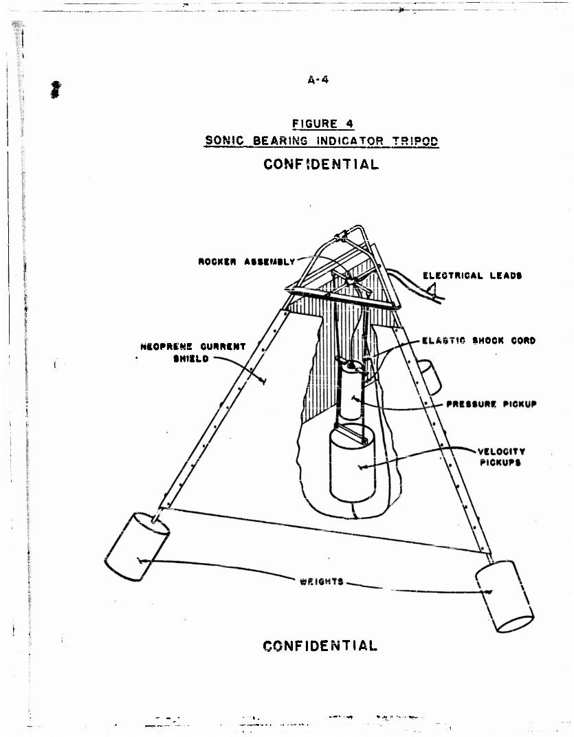
location in s. vertical pn«Hion with known azimuthal orientation. Figure
h is a cut-away view cf a tripod about 6 feet high used in intensity
meter operation. The rocker arm assembly provides for self-leveling of
the detectors in the event that the tripod settles on a rough or soft
bottom, The suspension of the detectors on two cords insures steady
CONFIDENTIAL

I \
CONFIDENTIAL
-11-
crientation of the velocity sensitive detectors„ The elasticity of these
cords provides the necessary vibration isolation and acoustic decoupling.
The rubber screen provides protection from tide and wave acion, but does
not have a significant influence on the sound field. This screen has
been removed in all lake tests previously reported. The tripod has been
satisfactory for all shore based tests.
The photograph of Figure 5 shows the original plan for mounting
the detectors for bottom impedance measurement. The spherical velocity
detector has sufficient buoyancy to support the pressure pickup and the
necessary cable Junction box. The use of shock cord provides mechanical
(acoustic) isolation from the 90 pound anchor. The sphere is secured in
a manner which provides self-righting ability in the presence of water
currents. This model does not permit the sound detectors to be near
enough to the bottom nor near enough together for the shortest wave lengths
anticipated, and its use h&s been discontinued.
The tripod of Figure 6 permits a shock cord suspension of the
pickup. Random asimuthal orientation is permissible in this case. This
design also allows self-righting of the detector unit with mechanical
isolation. The airplane shock cord has provided good elastic properties
to the detector mountings. The rubber has net deteriorated in a month'e
use under salt water; however, it is not recommended for permanent installa-
tions .
CONFIDENTIAL

*t-
CONFIDENTIAL
-12-
V. RESULT!?
Detectors have been constructed permitting underwater pound direction
indication from a single instrument station with system sensitivity over
a frequency band from 20 to f?(X) cycles per second. The figures in the
appendix show these detectors and merit some additional discussion.
Several forms of velocity signal detectors or pickups hnv* h««n
constructed which use geophones as sensitive elements. The sket3h of
Figure 1 indicates the general form of a velocity detector used in tests
at San Diego^ ' and at Beavertail Point5 Rhode Island. It has been
discussed in Section III. The can which is anodized to retard corrosion
ia Ut inches in diameter and $\ inches high. The unit weighs *>\ pounds.
A mounting bar at the top is provided for suspending the detector by a
shock cord. Water proof electric plugs connect the signal cable to the
geophones through the bottom end plate. Both the top and bottom plates
screw into the aluminum can with an 0-ring seal. Two geophones are shown
recessed in an aluminum block within the can, Mounted in this way, they
provide two horizontal components of acoustic velocity signal. The sensitiv-
ity is about 278 microwatts per inch per second. The source impedance is
215 ohms.
A slightly taller model has been constructed containing three g«o-*
phones. The construction is similar to that of the two element detector
with an additional vertically sensitive geopnone mounted in the top of
the block. This device gives three perpendicular components of acoustic
velocity signal* The specific gravity of this detector unit is 1.7 which
:ONFIDENTlAL

CONFIDENTIAL
.13-
gives a coupling of 1-11, as mentioned in Section III.
Figure 2 shows a detector used in acoustic impedance measurement.
The sketch of Figure 3 indicates the pressure detector construction more
clearxy. The sound pressure ie transmitted to the barium titanate through
the rubber at tne sides and through the metal plates at each eni. The
crystal cylinder is U" long X 2W O.D„ with a 3/lG" wall.*6' Its sensitiv-
ity is l£ microvolts per dyne per square centimeter,, A preamplifier employ-
ing a type GE 5?5l vacuum tube provides a signal amplification of 100, and
an output impedance less than 10 ohms*
The detectors shown in Figures 1 and 3 are mounted as shown in
Figure U„ The Liipod, described in Section IV, is used as an instrument
station on the sea bottom for sound direction indication.
As a component of the bottom impedance meter, a velocity detector
was used having a density (gravity) less than one gm/era^. In this model,
shown in Figure 5, a large laminated wooden ball 16 inches in diameter
was used for floating and coupling a vertically sensitive geophone.
(This was discussed in Section IV.) With a density of about 0.33, the
wooden ball velocity detector has a water coupling of 1.8. This drops to
l.U at 1000 cps when a phase shift of about h degrees occurs betwoen the
ball and the water. The unit has not had adequate tests for spurious
resonant singularities in its response curve. The use of this detector
has been discontinued because it is too large in terms of wave length at
500 cycles.
*. new detector has been constructed for the impedance meter. It
consists of a barium titanate cylinder in a rubber sleeve with an amplifier
CONFIDENTIAL

CONFIDENTIAL
-u»- and gsophone inside, The parts are shown in Figure 2 and the assembled
unit supported by a tripod is shown in Figure 6„ The Reophone unit is
electrically separate from the pressure detector and amplifier, although
its leads are brought to the instrument panel through the same plug and
cable. This unit has a density of 3.1 which corresponds to a velocity
coupling to the water of 0.73. Complete dynamic balance of the Jjupedanca
rater units has not been atlwpted as it is to b« used in only the vertical
position with vertically traveling sound waves.
CONFIDENTIAL

CONFIDENTIAL
-i<-
VI. CONCLUSION
Low frequency dstsctcrs with vide practical applications in under-
water sound may be constructed for response to either or63sure or velocity.
Good sensitivity is obtained with conventional design if attention is gi^cn
to the details presented in this report. Similar detectors have been used
for both bottom impedance measurement and for acoustic intensity measure-
ment. Other sonic devices may also be adapted to the low frequency spectrum
partly by incorporating these low frequency detectors.
The velocity detectors described offer several posaxbilities which
have not been emphasized. Their cosine* low sensitivity pattern permits
directional effects which era impractical at long wave lengths by ar.y other
method. Their lack of a diaphragm, or window, or sensitive surface makes
them indifferent to static pressure effects cr other forms of rough aervice.
Their small size permits great flexibility in their application. Since
their operation is independent of special materials or phenomena, an
accurate sensitivity calibration will be maintained over a wide range of
temperatures and vibration amplitudes. It is hoped that this report will
promote their popularity in the field of underwater sound.
CONFIDENTIAL

CuNFiDriN i IAL
-16-
REFERENCES
1. Principleg of Underwater Sound, reprinted and distributed by the Research Analysis Group, Committee on Undersea Warfare, National Research Council.
2. Mechanical Vibrations. Den Hartog, McGraw Hill (I9ii0),
3. Transients in Linear Systems, Gardner and Barnes, Wiley it Sons (iyu?)
!i. Piastre TechrJsal Instrument Company, 50h Waugh Drive, Houston, Texas.
5. Motion of Rigid Sphere in an Acoustic Wave Field. Alfred Wolf, Qeo- 5hysicic"Vorix \k$ P. n> "~ —
6. Brush Development Company, 3322 Perkins Avenue, Cleveland, Ohio*
7. A Study ftf Scattering of Sound Waves in Fluids - Part i, F. C. Karal, Technical Report 68crd5)-2, June 16, i$53I "
8. Report on Tests of the Underwater Sound Intensity He^er ror Locating Transitory Sources. R. L. Mills. Technical Report 660(OO)-5. January l87"17?Ur "
9. First Sea Tests of the Underwater Acoustic Intensity Metar, J, K. White, Technical leport 630(00)-l, January 26, 1953.
10. M B Manufacturing Company, New Haven, Connecticut=
11. Acoustic and Seismic Detection and Location of Mine and Missile Splashes - PartIIt
John C. Munson and Homer N. Opl&nd, presented as paper uo at the Eighth Navy Symposium on Underwater Acoustics, Novastoer 19, 20, 1953, New London, Connecticut.
12. H.M. U.C.W.E. Informal Report N0. 15U7/52 - "Preliminary Trials Concerned with Possible Application of Geophone Stations in Minewatching'1, July 25, 1952, Dr. F, V. Flint.
:ONF!DENTiAL

:
I I i
CONFIDENTIAL
-17-
APPSNDIX
CONFIDENTIAL
.i . . •*• nr\

I
i I
i
CONFIDENTIAL -18-
APFSNDIX
TABLE OF CONTENTS
Page
Figure 1 - Sketch ox Geophone Assembly A-l
Figure 2 - Bottom Impedance Meter Pickup A»2
Figure 3 - Pressure Detector A-3
Figure h - Sonic Bearing Indicator Tripod A-lj
Figure $ - Bottom Impedance Meter Pickups A-<
Figure 6 - Bottom Impedance M*t«r Tripod A-6
CONFIDENTIAL

:.
I A-!
i
! : :
CONFIDENTIAL
ALUMINUM - CAN
OEOPHONEt
/ X
FIGURE I SKETCH OF
GEOPHONE ASSEMBLY
CONFIDENTIAL
I

.
-»»—
A -O
'
::
H Z U O L» z: o w
i
1 ' :
1 FIG
UR
E
2

j
• - J
CONFIDENTIAL
PLUG
H08I CLAMP
tf-WMH SLIIVE
CCRAMIO CYLINDER
w&vzk 'BRASS PLATt
FIGURE 3 PRESSURE QETECTOS
CONFIDENTIAL
i
I A'«»
FIGURE 4 SONIC BEARING INDICATOR TRSPQD
CONFtDENTIAL
*af\ ROCKER ASSEMBLY
ELECTRICAL LEADS
NEORRIHS CURRENT SHIELD
!fi SHOCK CORD
CONFIDENTIAL
* •>} " '« " **"

w ONFtDENTIAL
FIGURE 5
•
BOTTOM IMPEDANCE METER PICKUPS
CONFIDENTIAL

A~%>
•
i ..•••• 'i,- ,- •. • J.\. . <>
• ,' • ; •• ••• : • /<--.
i
.-,•••' CONFIDENTIAL