Embed Size (px)
Citation preview
multi-use residential
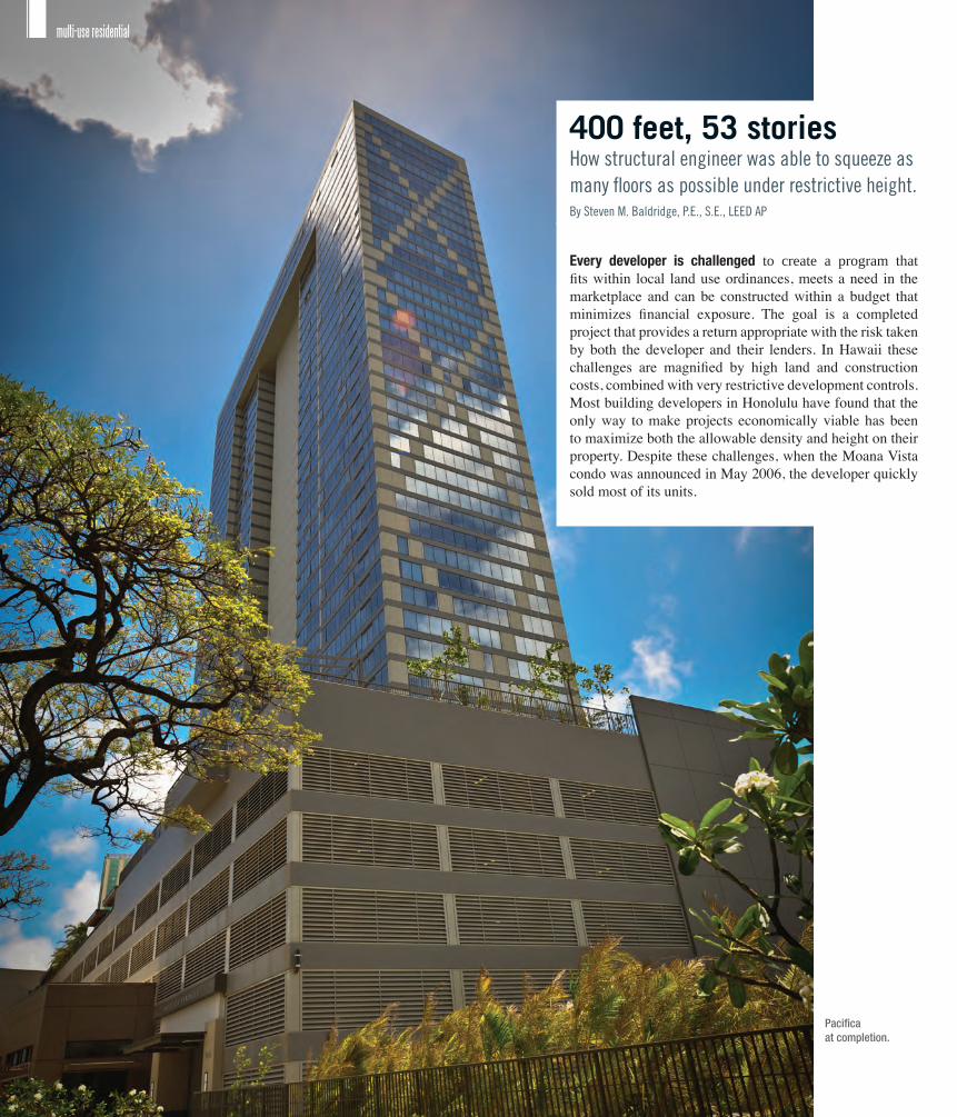
400 feet, 53 storiesHow structural engineer was able to squeeze as many floors as possible under restrictive height.By Steven M. Baldridge, P.E., S.E., LEED AP
Every developer is challenged to create a program that fits within local land use ordinances, meets a need in the marketplace and can be constructed within a budget that minimizes financial exposure. The goal is a completed project that provides a return appropriate with the risk taken by both the developer and their lenders. In Hawaii these challenges are magnified by high land and construction costs, combined with very restrictive development controls. Most building developers in Honolulu have found that the only way to make projects economically viable has been to maximize both the allowable density and height on their property. Despite these challenges, when the Moana Vista condo was announced in May 2006, the developer quickly sold most of its units.
Pacificaat completion.
www.gostructural.com July 2012 Structural Engineer 17
Height restrictionsIn Honolulu, it is not unusual to find buildings with floor-to-floor heights less than 8 feet, 6 inches in order to maximize floor count within restrictive height limitations. The structural systems for these projects have included short span tunnel-formed slabs as well as thin post-tensioned slabs, with many older projects utilizing a slab thickness of only 5 inches. The Moana Vista project had to take a similar approach in order to squeeze 53 distinct levels within a maximum height limit of 400 feet to the top of the roof slab.
Important architectural requirements related to space planning and function within the residential units dictated column location initially. An additional consideration on this project, however, was that the residential tower needed to be situated over parking levels squeezed onto a very tight site. In order to avoid deep, costly and materially consuming transfer girders, the column layout had to take into consideration the residential floor requirements and the parking stall and drive aisle requirements below the tower.
The architect and structural engineer met to massage the column layout to help minimize the few longer spans that could impact the entire system. Where column locations could not be adjusted, discussions were extended to the design/assist contractor, Hawaiian Dredging Construction Co. These early discussions and collaboration resulted in adjustments to the final column locations to achieve the desired functional layout with consideration of creating a low profile structural floor system.
Slab systemsThe footprint of the residential tower was 63 feet wide by 223 feet long, supported on top of a 138-foot-wide by 508-foot-long parking and recreation deck podium. Post-tensioning of the floors was required to create a thin enough structural system to meet the programming requirements within the height restriction. Such a long building required the careful application of pour strips to minimize shrinkage cracking.
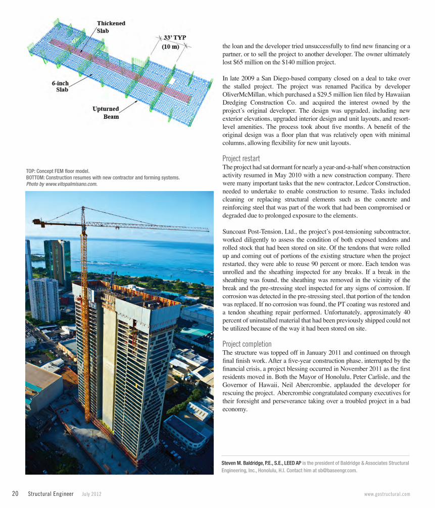
In the long direction of the building, column spacing needed to be up to 33 feet. With the availability of new forming systems, engineers determined that the slab thickness could be changed across the floor plate with little difficulty. Banded slabs were used inside the building to span the longer distance. The resulting reduction in the number of columns and their foundations justified having two different slab thicknesses in the floor system.
On the building perimeter the longer spans were accommodated by an upturned beam. This decision again resulted from the team’s collaborative efforts. From a structural standpoint, this beam allowed a much longer span than the 6-inch floor system could accommodate. Architecturally, a low upturn did not obstruct views out of the residential units and created a rhythm to the exterior look. Because the beam was upturned, the difficulty of formwork was reduced. This system also resulted in cost savings for the building’s exterior cladding as the concrete was less expensive than the glazing system at the residential units or the vented grill at the parking levels.
While relatively simple in plan, the deflection characteristics of a floor system with varying spans and element thicknesses warranted the increased accuracy of a three-dimensional finite element analysis to verify performance of the thin slab systems. The final configuration allowed the required 8-foot by 6-inch floor-to-floor height in the residential units and an approximately 8-foot floor-to-floor height in the parking areas in levels split down the length of the project 4 feet apart, connected by short ramps for vehicle circulation up the building.
Structural expressionDuring early team meetings Joe Farrell, the team’s principal and design architect, with Architects Hawaii Limited, embraced a collaborative design spirit by soliciting ideas and input from the consultants. Farrell said it was very helpful that Baldridge & Associates Structural Engineering, Inc. came up with multiple solutions for the end bracing of this tall building so early in the design process. Having admired the expression of structure on numerous projects,
18 Structural Engineer July 2012 www.gostructural.com
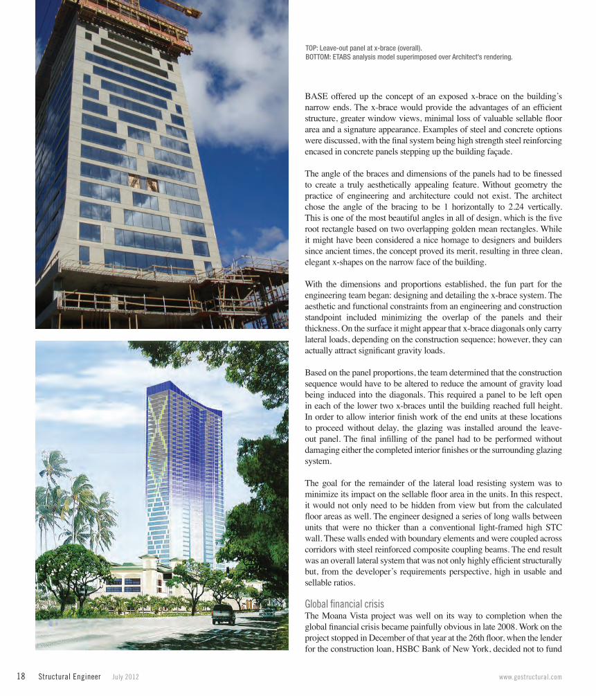
BASE offered up the concept of an exposed x-brace on the building’s narrow ends. The x-brace would provide the advantages of an efficient structure, greater window views, minimal loss of valuable sellable floor area and a signature appearance. Examples of steel and concrete options were discussed, with the final system being high strength steel reinforcing encased in concrete panels stepping up the building façade.
The angle of the braces and dimensions of the panels had to be finessed to create a truly aesthetically appealing feature. Without geometry the practice of engineering and architecture could not exist. The architect chose the angle of the bracing to be 1 horizontally to 2.24 vertically. This is one of the most beautiful angles in all of design, which is the five root rectangle based on two overlapping golden mean rectangles. While it might have been considered a nice homage to designers and builders since ancient times, the concept proved its merit, resulting in three clean, elegant x-shapes on the narrow face of the building.
With the dimensions and proportions established, the fun part for the engineering team began: designing and detailing the x-brace system. The aesthetic and functional constraints from an engineering and construction standpoint included minimizing the overlap of the panels and their thickness. On the surface it might appear that x-brace diagonals only carry lateral loads, depending on the construction sequence; however, they can actually attract significant gravity loads.
Based on the panel proportions, the team determined that the construction sequence would have to be altered to reduce the amount of gravity load being induced into the diagonals. This required a panel to be left open in each of the lower two x-braces until the building reached full height. In order to allow interior finish work of the end units at these locations to proceed without delay, the glazing was installed around the leave-out panel. The final infilling of the panel had to be performed without damaging either the completed interior finishes or the surrounding glazing system.
The goal for the remainder of the lateral load resisting system was to minimize its impact on the sellable floor area in the units. In this respect, it would not only need to be hidden from view but from the calculated floor areas as well. The engineer designed a series of long walls between units that were no thicker than a conventional light-framed high STC wall. These walls ended with boundary elements and were coupled across corridors with steel reinforced composite coupling beams. The end result was an overall lateral system that was not only highly efficient structurally but, from the developer’s requirements perspective, high in usable and sellable ratios.
Global financial crisisThe Moana Vista project was well on its way to completion when the global financial crisis became painfully obvious in late 2008. Work on the project stopped in December of that year at the 26th floor, when the lender for the construction loan, HSBC Bank of New York, decided not to fund
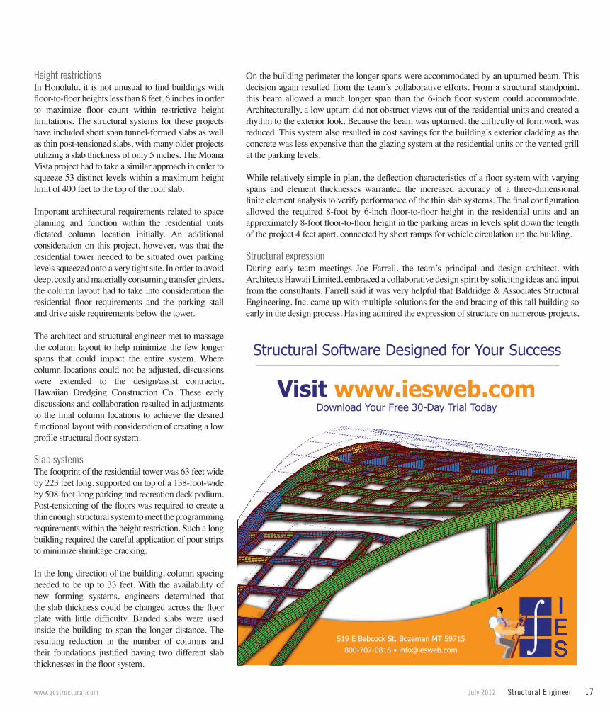
TOP: Leave-out panel at x-brace (overall).BOTTOM: ETABS analysis model superimposed over Architect’s rendering.
20 Structural Engineer July 2012 www.gostructural.com
the loan and the developer tried unsuccessfully to find new financing or a partner, or to sell the project to another developer. The owner ultimately lost $65 million on the $140 million project.
In late 2009 a San Diego-based company closed on a deal to take over the stalled project. The project was renamed Pacifica by developer OliverMcMillan, which purchased a $29.5 million lien filed by Hawaiian Dredging Construction Co. and acquired the interest owned by the project’s original developer. The design was upgraded, including new exterior elevations, upgraded interior design and unit layouts, and resort-level amenities. The process took about five months. A benefit of the original design was a floor plan that was relatively open with minimal columns, allowing flexibility for new unit layouts.
Project restartThe project had sat dormant for nearly a year-and-a-half when construction activity resumed in May 2010 with a new construction company. There were many important tasks that the new contractor, Ledcor Construction, needed to undertake to enable construction to resume. Tasks included cleaning or replacing structural elements such as the concrete and reinforcing steel that was part of the work that had been compromised or degraded due to prolonged exposure to the elements.
Suncoast Post-Tension, Ltd., the project’s post-tensioning subcontractor, worked diligently to assess the condition of both exposed tendons and rolled stock that had been stored on site. Of the tendons that were rolled up and coming out of portions of the existing structure when the project restarted, they were able to reuse 90 percent or more. Each tendon was unrolled and the sheathing inspected for any breaks. If a break in the sheathing was found, the sheathing was removed in the vicinity of the break and the pre-stressing steel inspected for any signs of corrosion. If corrosion was detected in the pre-stressing steel, that portion of the tendon was replaced. If no corrosion was found, the PT coating was restored and a tendon sheathing repair performed. Unfortunately, approximately 40 percent of uninstalled material that had been previously shipped could not be utilized because of the way it had been stored on site.
Project completionThe structure was topped off in January 2011 and continued on through final finish work. After a five-year construction phase, interrupted by the financial crisis, a project blessing occurred in November 2011 as the first residents moved in. Both the Mayor of Honolulu, Peter Carlisle, and the Governor of Hawaii, Neil Abercrombie, applauded the developer for rescuing the project. Abercrombie congratulated company executives for their foresight and perseverance taking over a troubled project in a bad economy.
Steven M. Baldridge, P.E., S.E., LEED AP is the president of Baldridge & Associates Structural Engineering, Inc., Honolulu, H.I. Contact him at [email protected].
TOP: Concept FEM floor model.BOTTOM: Construction resumes with new contractor and forming systems.Photo by www.vitopalmisano.com.