Embed Size (px)
Citation preview
www.tcsbasys.com PH: 800.288.9383 W1
Wiring Basics
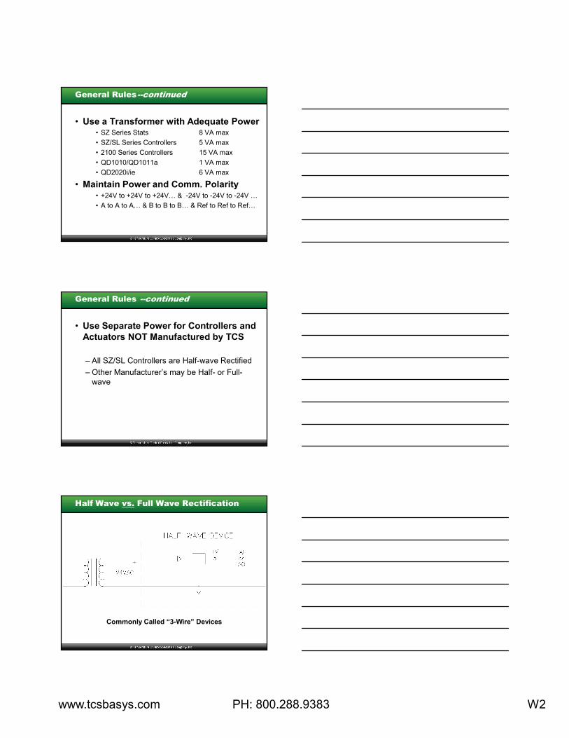
General Rules
• Use Dedicated Power with Networked
Systems – DO NOT USE UNIT POWER
• Use Separate Power for all Relays
– Both of these precautions help eliminate the
potential for noise on the communication lines.
www.tcsbasys.com PH: 800.288.9383 W2
General Rules--continued
• Use a Transformer with Adequate Power• SZ Series Stats 8 VA max
• SZ/SL Series Controllers 5 VA max
• 2100 Series Controllers 15 VA max
• QD1010/QD1011a 1 VA max
• QD2020i/ie 6 VA max
• Maintain Power and Comm. Polarity• +24V to +24V to +24V… & -24V to -24V to -24V …
• A to A to A… & B to B to B… & Ref to Ref to Ref…
General Rules --continued
• Use Separate Power for Controllers and
Actuators NOT Manufactured by TCS
– All SZ/SL Controllers are Half-wave Rectified
– Other Manufacturer’s may be Half- or Full-
wave
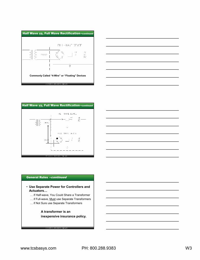
Half Wave vs. Full Wave Rectification
Commonly Called “3-Wire” Devices
www.tcsbasys.com PH: 800.288.9383 W3
Half Wave vs. Full Wave Rectification--continued
Commonly Called “4-Wire” or “Floating” Devices
Half Wave vs. Full Wave Rectification--continued
General Rules --continued
• Use Separate Power for Controllers and
Actuators…
… if Half-wave, You Could Share a Transformer
… if Full-wave, Must use Separate Transformers
… if Not Sure use Separate Transformers
A transformer is an
inexpensive insurance policy.
www.tcsbasys.com PH: 800.288.9383 W4
Inputs
General Practices – Inputs
• Use Shielded, Twisted-pair Cable
… Use the RED & BLACK Sensor Wires (clip white)
• Ground Shield at One End ONLY
… Preferably at the Sensor
• All Wire Has Resistance…
… Use the RTD Zero Pots to Fine Tune
Readings
a Couple of Degrees by Adjusting Them Slightly
(Only After all Other Inaccuracies are Eliminated)
General Practices – Inputs --continued
• DO NOT RUN Near High Voltage Wiring
… Fans, Variable Speed Drives, Ballasts
• If Must Run Near High Voltage Wiring,
… Stay at Least 2’ to 3’ Away if Parallel
… Cross Wiring Perpendicular to Each Other
www.tcsbasys.com PH: 800.288.9383 W5
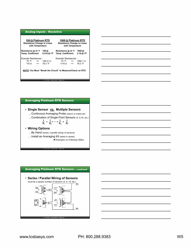
Analog Inputs - Resistive
100 ΩΩΩΩ Platinum RTDResistance Change is Linear
with Temperature
Resistance @ 32 °F 100 ΩΩΩΩ
Temp. Coefficient 0.216 Ω Ω Ω Ω /°F
Example Resistances -
70 °F => 108.21 Ω
110 Ω => 78.3 °F
1000 ΩΩΩΩ Platinum RTDResistance Change is Linear
with Temperature
Resistance @ 32 °F 1000 ΩΩΩΩ
Temp. Coefficient 2.16 Ω Ω Ω Ω /°F
Example Resistances -
70 °F => 1082.1 Ω
1110 Ω => 78.3 °F
NOTE: You Must “Break the Circuit” to Measure/Check an RTD
Averaging Platinum RTD Sensors
• Single Sensor vs. Multiple Sensors
…Continuous Averaging Probe (return or mixed air)
…Combination of Single Point Sensors (4, 9,16, etc.)
• Wiring Options
…By Hand (series / parallel wiring of sensors)
…Install an Averaging Kit (wired in series)
Examples on Following Slides
1
R1
—1
R2
—1
Rn
—1
RT
—+ + … + =
Averaging Platinum RTD Sensors-- continued
• Series / Parallel Wiring of Sensorsmust be a square number of sensors (4, 9, 16, etc.)
T1
T1
www.tcsbasys.com PH: 800.288.9383 W6
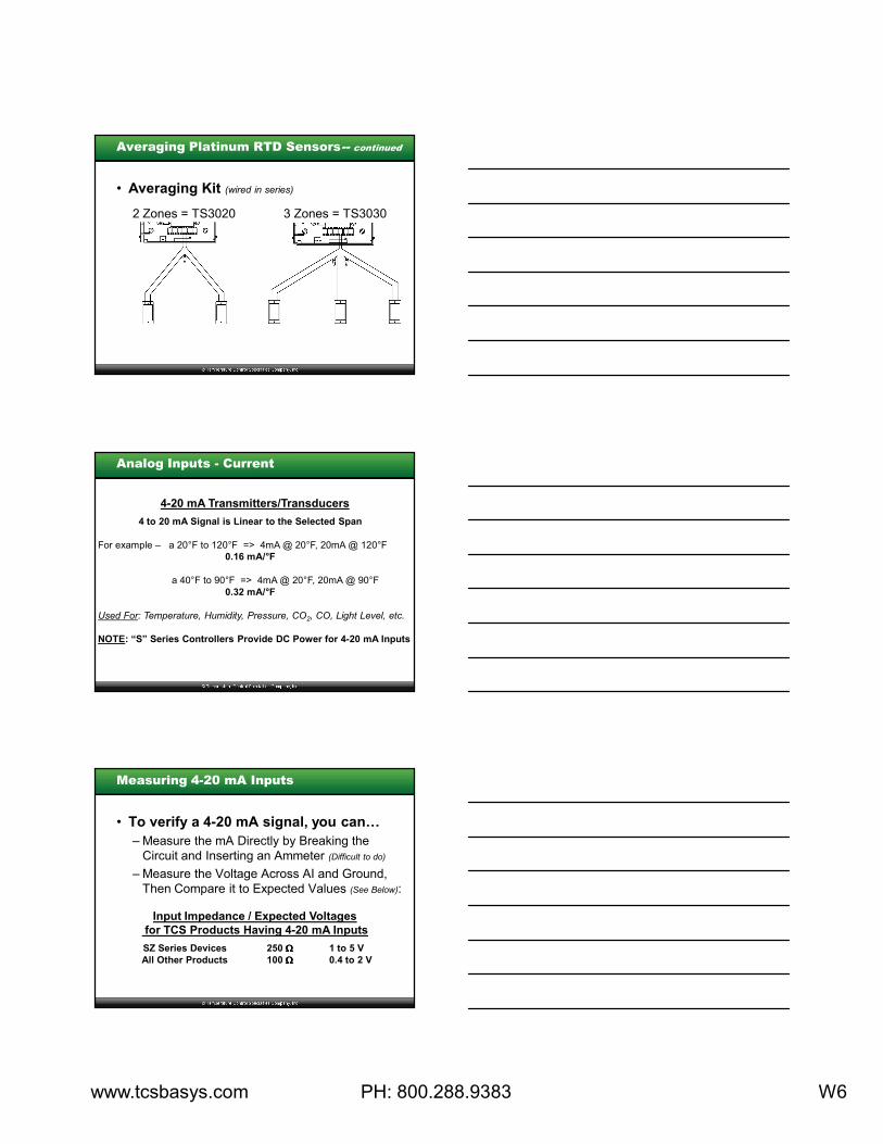
Averaging Platinum RTD Sensors-- continued
• Averaging Kit (wired in series)
2 Zones = TS3020 3 Zones = TS3030
4-20 mA Transmitters/Transducers
4 to 20 mA Signal is Linear to the Selected Span
For example – a 20°F to 120°F => 4mA @ 20°F, 20mA @ 120°F
0.16 mA/°F
a 40°F to 90°F => 4mA @ 20°F, 20mA @ 90°F
0.32 mA/°F
Used For: Temperature, Humidity, Pressure, CO2, CO, Light Level, etc.
NOTE: “S” Series Controllers Provide DC Power for 4-20 mA Inputs
Analog Inputs - Current
Measuring 4-20 mA Inputs
• To verify a 4-20 mA signal, you can…
– Measure the mA Directly by Breaking the
Circuit and Inserting an Ammeter (Difficult to do)
– Measure the Voltage Across AI and Ground,
Then Compare it to Expected Values (See Below):
Input Impedance / Expected Voltages
for TCS Products Having 4-20 mA Inputs
SZ Series Devices 250 ΩΩΩΩ 1 to 5 V
All Other Products 100 ΩΩΩΩ 0.4 to 2 V
www.tcsbasys.com PH: 800.288.9383 W7
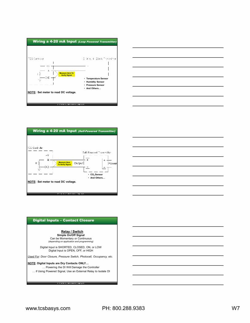
Wiring a 4-20 mA Input (Loop Powered Transmitter)
• Temperature Sensor
• Humidity Sensor
• Pressure Sensor
• And Others…
Measure Here To
Verify Signal
NOTE: Set meter to read DC voltage.
Wiring a 4-20 mA Input (Self-Powered Transmitter)
• CO2 Sensor
• And Others…
Measure Here
To Verify Signal
NOTE: Set meter to read DC voltage.
Relay / SwitchSimple On/Off Signal
Can be Momentary or Continuous(depending on application and programming)
Digital Input is SHORTED, CLOSED, ON, or LOW
Digital Input is OPEN, OFF, or HIGH
Used For: Door Closure, Pressure Switch, Photocell, Occupancy, etc.
NOTE: Digital Inputs are Dry Contacts ONLY…
… Powering the DI Will Damage the Controller
… if Using Powered Signal, Use an External Relay to Isolate DI
Digital Inputs – Contact Closure
www.tcsbasys.com PH: 800.288.9383 W8
Wiring a Digital Input --continued
Note: If all the controllers are powered
with the same transformer…
… you may use the same set of contacts
directly into up to 6 controllers.
Even in this case, we still recommend using
a relay with multiple, separate contacts at
the controller (or a peanut relay).
Outputs
General Practices – Digital Outputs
• Output Relays Rated at 24VAC @ 2 A
… if Power Exceeds this use a Pilot Relay
• Digital Outputs are Dry Contact (Not Powered)
… Power can be Supplied to External Relays by
Running Power to the “R” Terminal
• 2 sets of Power MUST NOT go to 1 Relay,
Either, use a Separate Transformer to Power “R”
or, Operate the 2nd Unit Through External Relay
www.tcsbasys.com PH: 800.288.9383 W9
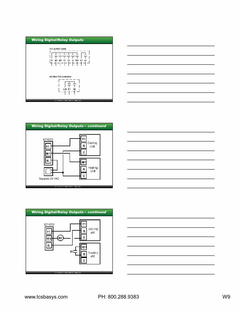
Wiring Digital/Relay Outputs
Wiring Digital/Relay Outputs -- continued
Wiring Digital/Relay Outputs -- continued
www.tcsbasys.com PH: 800.288.9383 W10
General Practices – Analog (4-20 mA) Outputs
• Analog Outputs Should Not be Powered
• We use “Current Source” Outputs
…Current is Pushed from the Controller Back to
Ground
• Analog Outputs can be Shared
… as a Current Signal
… as a Voltage Signal (preferable)
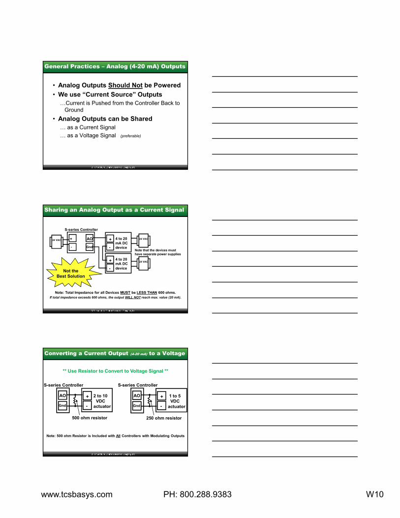
+
-
4 to 20
mA DC
device
AO
Gnd
S-series Controller
+
-
4 to 20
mA DC
device
24 VAC
24 VAC
24 VAC
Note that the devices must
have separate power supplies
+
-
Sharing an Analog Output as a Current Signal
Note: Total Impedance for all Devices MUST be LESS THAN 600 ohms.
If total impedance exceeds 600 ohms, the output WILL NOT reach max. value (20 mA).
Not the
Best Solution
Converting a Current Output (4-20 mA) to a Voltage
+
-
2 to 10
VDC
actuator
AO
Gnd
S-series Controller
500 ohm resistor
+
-
1 to 5
VDC
actuator
AO
Gnd
S-series Controller
250 ohm resistor
Note: 500 ohm Resistor is Included with All Controllers with Modulating Outputs
** Use Resistor to Convert to Voltage Signal **
www.tcsbasys.com PH: 800.288.9383 W11
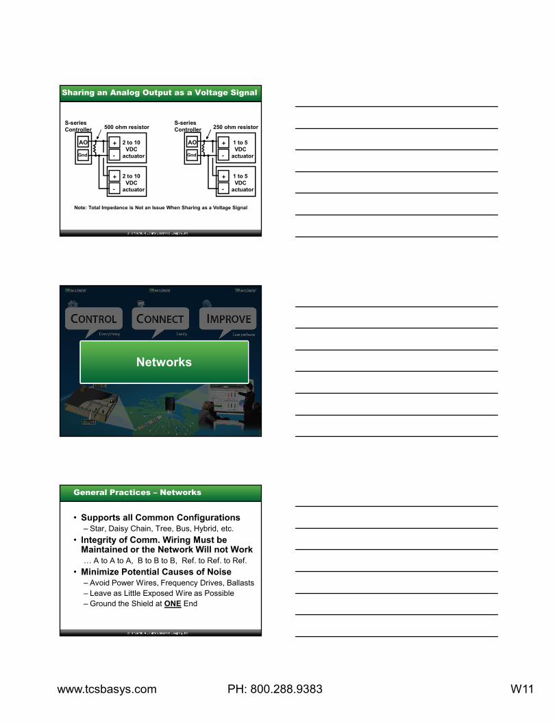
Sharing an Analog Output as a Voltage Signal
+
-
2 to 10
VDC
actuator
AO
Gnd
500 ohm resistor
+
-
1 to 5
VDC
actuator
AO
Gnd
S-series
Controller 250 ohm resistorS-series
Controller
+
-
2 to 10
VDC
actuator
+
-
1 to 5
VDC
actuator
Note: Total Impedance is Not an Issue When Sharing as a Voltage Signal
Networks
General Practices – Networks
• Supports all Common Configurations
– Star, Daisy Chain, Tree, Bus, Hybrid, etc.
• Integrity of Comm. Wiring Must be Maintained or the Network Will not Work
… A to A to A, B to B to B, Ref. to Ref. to Ref.
• Minimize Potential Causes of Noise
– Avoid Power Wires, Frequency Drives, Ballasts
– Leave as Little Exposed Wire as Possible
– Ground the Shield at ONE End
www.tcsbasys.com PH: 800.288.9383 W12
General Practices – Networks -- continued
• Each Device Has Unique Address (not 248)
• Baud Rate MUST be the Same Across the Entire Network (Stats, Controls, Comm. Devices)
• Install Terminating Resistor at Both Ends as Required
• See “Support Resources” – “FAQ Superstats™” Catalog page 355
– “Network Wiring and Setup” page 390
– “Troubleshooting Network Wiring” page 396
– “Checkout & Troubleshooting” on Product Ins.
Checking the Network Communication Bus
• Avoid Noise by Grounding the Shield –
AT ONE END ONLY
• Check the Voltages on the Comm. Bus
– Measure the Voltage Across the Specified
Points, Then Compare it to Values Shown BelowNote: These values do not guarantee network communication.
A to B 0 VAC 1 to 4 VDC
A to REF 0 VAC 0 to 1 VDC
B to REF 0 VAC 2 to 5 VDC
A or B to Shield 0 VAC 0 VDC
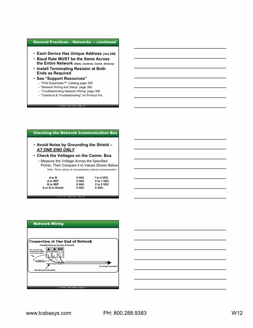
Network Wiring
www.tcsbasys.com PH: 800.288.9383 W13
Network Wiring -- continued
Terminal Block on Thermostat
Connection at the Thermostats (except end)
To S-series ControllersTo S-series Controllers
REF
Network Wiring -- continued
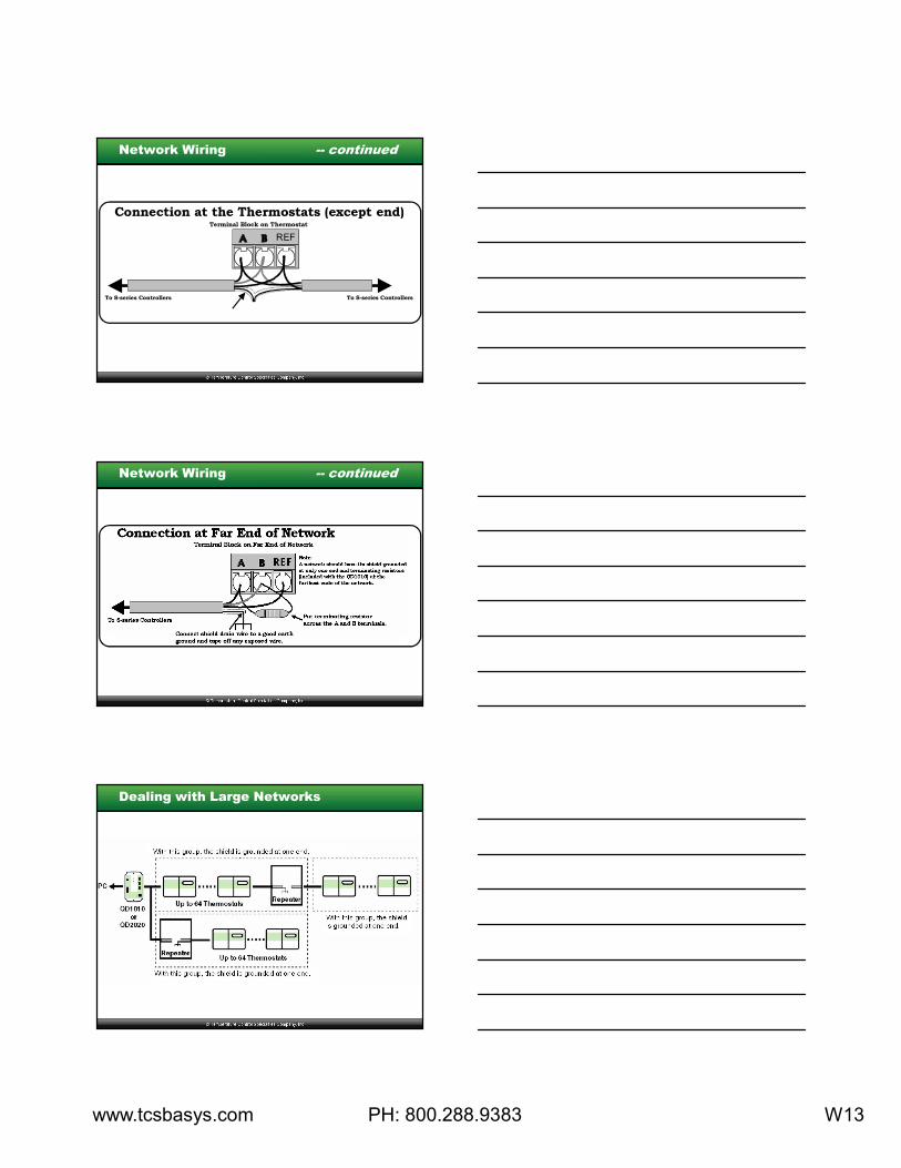
Dealing with Large Networks
www.tcsbasys.com PH: 800.288.9383 W14
How many repeaters do I need ?
# Controllers Length of Wire (ft.) # Repeaters
up to 64 up to 4,000 0
up to 128 up to 8,000 1
up to 192 up to 12,000 2
up to 255 up to 16,000 3
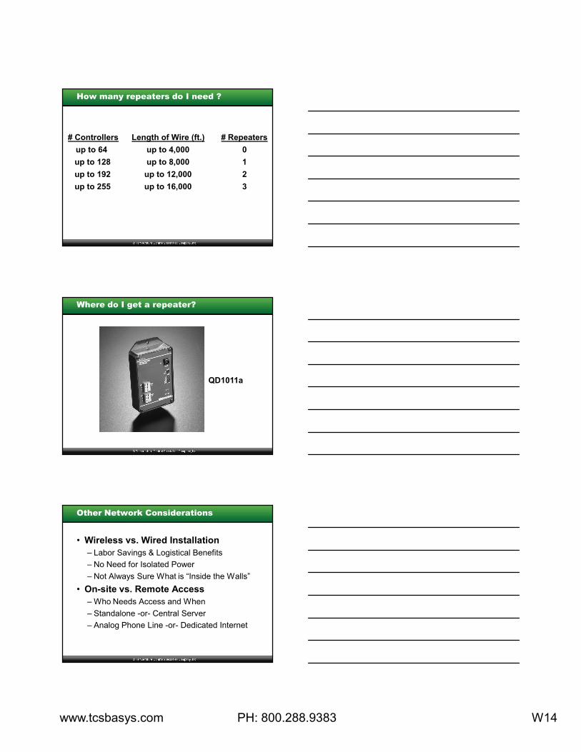
Where do I get a repeater?
QD1011a
Other Network Considerations
• Wireless vs. Wired Installation
– Labor Savings & Logistical Benefits
– No Need for Isolated Power
– Not Always Sure What is “Inside the Walls”
• On-site vs. Remote Access
– Who Needs Access and When
– Standalone -or- Central Server
– Analog Phone Line -or- Dedicated Internet
www.tcsbasys.com PH: 800.288.9383 W15
Wiring Troubleshooting
• See “Support Resources” – “FAQ Superstats™” Catalog page 355
– “Network Wiring and Setup” page 390
– “Troubleshooting Network Wiring” page 396
– “Checkout & Troubleshooting” on Product Ins.
• Verify A to A, B to B, Ref. to Ref.
*** DO NOT Use Shield as Ref. Wire ***
• Verify Power Polarity
• Verify Isolated Transformer(s)
Where to Get Help or Answers
• Instructions Sent with Product
• TCS Basys Controls Catalog
• Training & Reference Manual
• www.tcsbasys.com
• Call TCS Directly – 800-288-9383