Embed Size (px)
Citation preview

6th International Symposium on Friction Stir Welding Saint-Sauveur, Nr Montréal, Canada, October 10-13, 2006
C.A. Widener, et al.
HIGH-ROTATIONAL SPEED FRICTION STIR WELDING WITH A FIXED SHOULDER
PAPER 38
Widener, C.A. 1, Talia, J.E. 2, Tweedy, B.M. 1, and Burford, D.A. 1
1National Institute for Aviation Research, Wichita State University
2 Mechanical Engineering Department, Wichita State University,
Friction stir welding is an innovative solid-state joining technique that has been conventionally found to produce high quality joints in the range of 200-2000 rpm. Work at Wichita State University, however, has demonstrated that friction stir welding and processing with much higher spindle speeds is possible. The principle advantage of operating at higher rotation speeds is the ability to reduce the spindle torque and forging loads. The primary disadvantage is that reduced forging loads create more opportunities for the formation of weld defects like voids, wormholes and increased porosity. One way to overcome that challenge is through the introduction of a non-rotating shoulder surrounding the rotating pin, in order to maintain the necessary forging loads to prevent weld defects. This paper details the principal resultant metallurgy with comparisons made to representative traditional friction stir welded metallurgy. The resultant mechanical properties and process force analysis of the welded joints is also provided.
INTRODUCTION
Friction stir welding has been traditionally understood to mean creating a mechanical joint with the use of a rotating probe and shoulder at speeds of less than 3000 rotations per minute. Two exciting innovations on traditional friction stir welding have been investigated at Wichita State University, namely higher rotational speeds (>3000 rpm) and the use of a fixed shoulder surrounding a rotating probe, reference Fig. 1.
Fig.1 Fixed Shoulder Tool
Fixed – (non-rotating)

6th International Symposium on Friction Stir Welding Saint-Sauveur, Nr Montréal, Canada, October 10-13, 2006
C.A. Widener, et al.
The idea to investigate higher rotational speeds was originally conceived by Dr. Arthur C. Nunes at the NASA Marshall Space Flight Center and was demonstrated by Dr. Jorge E. Talia at Wichita State University in 2002 using a commercial router spindle, dubbing it High-Rotation Speed Friction Stir Welding (HRS-FSW). Due to the tendency to create porosity and weld defects at higher rotational speeds, a fixed shoulder to surround a rotating pin was suggested by Fred J. Callahan IV of Engineering Consulting Services, Statesville, NC to increase the forging pressure around the pin without overheating and galling the surface at high rotational speeds, and was also developed by Dr. Talia. The result was a defect free joint with an excellent surface finish, but at very low travel speeds. Shortly after, the fixed shoulder technique was adapted by Dr. Talia and Dr. Widener for use on conventional friction stir welding machines as a means to improve weld track surface finish and influence weld morphology. A summary of those results is being presented here for the first time, along with recent additional developments in this area.
BACKGROUND
HRS-FSW Development
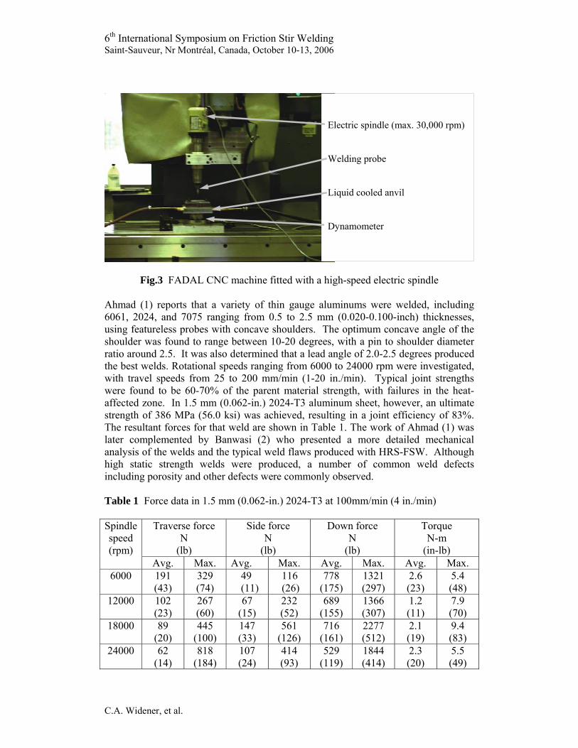
The first high speed friction stir welds were demonstrated using a portable high-speed friction stir-welding machine, consisting of a commercial electric router attached to an improvised table with a manual feed, ref. Fig.2. Following successful trial results with the portable machine, a FADAL VMC-4020 CNC milling machine was fitted with a high-speed electric spindle and a small liquid-cooled anvil which included a dynamometer for force measurement, see Fig.3.
Fig.2 Portable HRS-FSW Machine (1)
Electric router Spindle to hold the welding tool Guide with adjustable slots Working table Manual feeding mechanism
6th International Symposium on Friction Stir Welding Saint-Sauveur, Nr Montréal, Canada, October 10-13, 2006
C.A. Widener, et al.
Fig.3 FADAL CNC machine fitted with a high-speed electric spindle
Ahmad (1) reports that a variety of thin gauge aluminums were welded, including 6061, 2024, and 7075 ranging from 0.5 to 2.5 mm (0.020-0.100-inch) thicknesses, using featureless probes with concave shoulders. The optimum concave angle of the shoulder was found to range between 10-20 degrees, with a pin to shoulder diameter ratio around 2.5. It was also determined that a lead angle of 2.0-2.5 degrees produced the best welds. Rotational speeds ranging from 6000 to 24000 rpm were investigated, with travel speeds from 25 to 200 mm/min (1-20 in./min). Typical joint strengths were found to be 60-70% of the parent material strength, with failures in the heat-affected zone. In 1.5 mm (0.062-in.) 2024-T3 aluminum sheet, however, an ultimate strength of 386 MPa (56.0 ksi) was achieved, resulting in a joint efficiency of 83%. The resultant forces for that weld are shown in Table 1. The work of Ahmad (1) was later complemented by Banwasi (2) who presented a more detailed mechanical analysis of the welds and the typical weld flaws produced with HRS-FSW. Although high static strength welds were produced, a number of common weld defects including porosity and other defects were commonly observed.
Table 1 Force data in 1.5 mm (0.062-in.) 2024-T3 at 100mm/min (4 in./min)
Traverse force N
(lb)
Side force N
(lb)
Down force N
(lb)
Torque N-m
(in-lb)
Spindle speed (rpm)
Avg. Max. Avg. Max. Avg. Max. Avg. Max. 6000 191
(43) 329 (74)
49 (11)
116 (26)
778 (175)
1321 (297)
2.6 (23)
5.4 (48)
12000 102 (23)
267 (60)
67 (15)
232 (52)
689 (155)
1366 (307)
1.2 (11)
7.9 (70)
18000 89 (20)
445 (100)
147 (33)
561 (126)
716 (161)
2277 (512)
2.1 (19)
9.4 (83)
24000 62 (14)
818 (184)
107 (24)
414 (93)
529 (119)
1844 (414)
2.3 (20)
5.5 (49)
Electric spindle (max. 30,000 rpm) Welding probe Liquid cooled anvil Dynamometer

6th International Symposium on Friction Stir Welding Saint-Sauveur, Nr Montréal, Canada, October 10-13, 2006
C.A. Widener, et al.
Complimentary work in the area of HRS-FSW has also been conducted by Crawford et al. (3) at Vanderbilt University. They have helped to validate flow models which make it easier to understand the principle behind making welds at higher rotational speeds. Essentially, as rpm increases, the material flow dynamic changes and appears to become more fluid like around 5000 rpm. That finding helps to explain why flow models based on strain rate predictions alone would not predict the potential to create sound joints at high rpm. Nevertheless, HRS-FSW is far from being fully understood.
Fixed Shoulder Tool Development for HRS-FSW
Following the results of HRS-FSW, where the propensity for weld flash and weld porosity was observed, a fixed, non-rotating shoulder was developed to surround a rotating pin at high rpm. The result was a sound defect free joint in 6061-T4 when welded at very low speeds of 6.4 to 25 mm/min. Due to funding and equipment constraints, other parameters were not investigated. The tool and the resultant weld can be seen in Fig.4. The tensile results for the fixed shoulder tool weld are shown in Table 2, and are typical of conventional friction stir welding strengths. A picture of the weld nugget is shown in Fig.5, with lines for the pin and fixed shoulder diameters overlaid on the micrograph. There is clearly a secondary, induced stir zone (ISZ) below the pin. Even the original joint line between the plates has been deformed and is barely visible.
a) b) Fig.4 a) HRS-FSW pin tool with fixed shoulder, b) FSW in 6061-T4 at 6.4 mm/min
Table 2 Tensile results for a fixed shoulder HRS-FSW in 3.2 mm 6061-T4
Tensile Strength MPa (ksi)
% Elongation Weld/Parent Strength Ratio
Average 195.4 (28.3) 5.7 0.85 Std. Dev. 9.2 (1.3) 1.6

6th International Symposium on Friction Stir Welding Saint-Sauveur, Nr Montréal, Canada, October 10-13, 2006
C.A. Widener, et al.
Fig.5 Multi-Step Over-etch/Repolish Composite Photo of 3.2 mm 6061-T4 with a Fixed Shoulder (Feed = 25 mm/min at 15,000 rpm)
Fixed Shoulder Tool Development for Low Rotation Speed FSW
Work on the fixed shoulder was continued by Widener (4), also at Wichita State University, under a program funded by the State of Kansas, local industry, and the Federal Aviation Administration. It was hypothesized that if the fixed shoulder made such a large improvement at high rotational speeds, then it may also be beneficial at lower rotational speeds. Therefore, a fixed shoulder tool was designed to adapt to a conventional friction stir machine, as shown in Fig.6. This method combines a fixed shoulder that surrounds the traditional rotating pin and shoulder of fixed-pin FSW, compressing the material near the joint. The result is that weld flash can be eliminated, giving a smooth surface finish on both the top and bottom sides of the weld.
Fig.6 Fixed Shoulder Tool Design
(3 mm)
(3 mm)
(12.5 mm)
(1.4 mm)
Joint line deformed and barely visible

6th International Symposium on Friction Stir Welding Saint-Sauveur, Nr Montréal, Canada, October 10-13, 2006
C.A. Widener, et al.
A standard FSW pin tool is surrounded by a stainless steel bushing, which applies an additional down force on the material, constraining the z-direction on the top surface. This additional force prevents surface irregularities such as flash, which have been shown to be related to fatigue initiation sites by Bussu and Irving (5). It may also improve fatigue life by inducing a layer of compressive stresses in the top surface, creating an effect similar to low plasticity burnishing. Jayaraman et al. (6) showed that the layer of compressive stresses induced into the surface of the weld by low plasticity burnishing could improve fatigue life.
RESULTS
Low Rotation Speed FSW with a Fixed Shoulder
A friction stir weld was produced in 3.2mm (0.125-in.) 7075-T73 at 600 rpm and 203 mm/min (8 ipm) with and without a fixed shoulder. The surface finish produced by the fixed shoulder weld is shown in shown in Fig.7. A comparison of the improvement in the surface roughness in the weld track produced by the fixed shoulder compared to two examples of conventional friction stir welding and the parent material is shown in Fig. 8.
Fig.7 Close-up of FSW Surface Using a Fixed Shoulder Tool
Weld Track Surface Roughness Comparison
0
2
4
6
8
10
12
μm
Fixed Shoulder Parent Material Best FSW Typical FSW Fig.8 Comparison of Weld Track Surface Roughness in Friction Stir Welds
Note: Measurements taken longitudinally in the center of the weld track against the direction of welding.
20 mm

6th International Symposium on Friction Stir Welding Saint-Sauveur, Nr Montréal, Canada, October 10-13, 2006
C.A. Widener, et al.
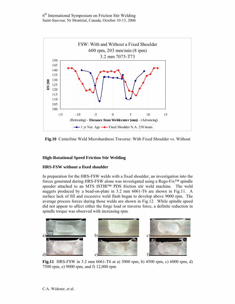
Some very interesting observations were made from the preliminary investigations of the weld microstructure using optical microscopy. First, looking at the weld macros in Fig. 9, it can be clearly seen that although the two welds were produced using the same weld parameters on the same machine and using the same fixed-pin tool, they have similar but quite different microstructure. The only difference between the two welds is the presence of a fixed shoulder surrounding the pin tool in (A) versus the fixed pin tool alone (B). The presence of the fixed shoulder tool seems to have a changed the shape of the nugget zone, and the heat-affected zone for the fixed shoulder appears larger and wider. Next, both the advancing and retreating sides of the weld produced with the fixed shoulder differ substantially. For the fixed shoulder tool, the advancing side is smoother and the retreating side is more dispersed.
Fig. 9 A Comparison of Weld Macros Using a Conventional Fixed Pin Tool
(A) With Fixed Shoulder Tool and (B) Without It was also noted that the grain size using the fixed shoulder tool is about twice as coarse as the conventional weld nugget, roughly 10 to 12 μm as opposed to 5 to 7 μm. Finally, it should be noted that these results are preliminary findings from only one weld made using this tooling, which is actually a bead on plate, not a butt-weld. Nevertheless, it is expected that these preliminary results are representative of the effects of this new type of tooling. When the hardness of the fixed shoulder tool weld is compared to a similar weld made without a fixed shoulder, as shown in Fig.10, it has a wider heat-affected zone and higher overall hardness across the respective weld zones. The higher hardness values are most likely due to the additional quenching effect of the fixed shoulder, which is in intimate contact with the top surface of the weld and is acting to remove heat from the weld zone. The increased width of the heat-affected zone is also evidence that the fixed shoulder exerts a subsurface influence on the material despite the fact that it is not rotating, similar to that observed previously with HRS-FSW. It should be noted, however, that these observations are from only one sample and that the fixed shoulder weld with 250-hours is being compared to the one-year naturally aged sample from the preliminary testing. Nonetheless, there a clear effect from the fixed shoulder.
(A)
(B)
1mm
1mm
6th International Symposium on Friction Stir Welding Saint-Sauveur, Nr Montréal, Canada, October 10-13, 2006
C.A. Widener, et al.
FSW: With and Without a Fixed Shoulder600 rpm, 203 mm/min (8 ipm)
3.2 mm 7075-T73
100105110115120125130135140145150
-15 -10 -5 0 5 10 15 (Retreating) - Distance from Weldcenter (mm) - (Advancing)
HV
200
1 yr Nat. Age Fixed Shoulder N.A. 250 hours
Fig.10 Centerline Weld Microhardness Traverse: With Fixed Shoulder vs. Without
High-Rotational Speed Friction Stir Welding
HRS-FSW without a fixed shoulder
In preparation for the HRS-FSW welds with a fixed shoulder, an investigation into the forces generated during HRS-FSW alone was investigated using a Rego-Fix™ spindle speeder attached to an MTS ISTIR™ PDS friction stir weld machine. The weld nuggets produced by a bead-on-plate in 3.2 mm 6061-T6 are shown in Fig.11. A surface lack of fill and excessive weld flash began to develop above 9000 rpm. The average process forces during those welds are shown in Fig.12. While spindle speed did not appear to affect either the forge load or traverse force, a definite reduction in spindle torque was observed with increasing rpm.
a) b) c)
d) e) f)
Fig.11 HRS-FSW in 3.2 mm 6061-T6 at a) 3000 rpm, b) 4500 rpm, c) 6000 rpm, d) 7500 rpm, e) 9000 rpm, and f) 12,000 rpm
1mm

6th International Symposium on Friction Stir Welding Saint-Sauveur, Nr Montréal, Canada, October 10-13, 2006
C.A. Widener, et al.
a)
Average Weld Traverse Force
050
100150200250
0 3000 6000 9000 12000
RPM
New
tons
b)
Average Weld Forge Force
0
500
1000
1500
0 3000 6000 9000 12000
RPM
New
tons
c)
Average Spindle Torque
0
5
10
15
20
0 3000 6000 9000 12000
RPM
N-m
Fig. 12 Process Forces Generated in 3.2 mm 6061-T6 Versus RPM
HRS-FSW with a fixed shoulder
The fixed shoulder setup used for the follow-on HRS-FSW work with a fixed shoulder is shown in Fig. 13 a), including the pin tool b) and spindle speeder c). In this case a traditional pin and shoulder tool was used, rather than the pin-only tool originally investigated, so that both with and without the fixed shoulder conditions could be investigated. The fixed shoulder shown below includes a pressure cylinder which surrounds the spindle speeder and allows the force on the fixed shoulder to be varied. Using a 12.7 mm fixed shoulder diameter with a 6.9 mm rotating pin tool a down force of approximately 4000 N (900 lb) was found to be adequate.
a) b) c) Fig.13 HRS-FSW Setup with a Fixed Shoulder on an MTS ISTIR™ PDS System

6th International Symposium on Friction Stir Welding Saint-Sauveur, Nr Montréal, Canada, October 10-13, 2006
C.A. Widener, et al.
The initial butt-weld produced using the fixed shoulder was produced at 600 rpm and 127 mm/min, which was a lower rpm and higher travel speed than the original HRS-FSW fixed shoulder experiment. The result is compared to an identical butt-weld without the fixed shoulder in Figs. 14 and 15. The residual oxide from the faying surface between the two plates is visible in the nugget in both instances; however, it appears to be more pronounced with the fixed shoulder. Without the fixed shoulder, a large wormhole is also evident on the advancing side of the weld nugget, while with the fixed shoulder the wormhole was greatly reduced, but not eliminated entirely in this case. The lips of the weld track are also clearly visible in Fig. 14, however, the fixed shoulder has retained a smooth weld track surface. The heat-affected zone is also again seen to be much wider in the weld with the fixed shoulder.
Fig.14 As-welded HRS-FSW Butt-Weld in 6061-T6 at 6000 rpm, 127 mm/min
Fig.15 As-Welded Fixed Shoulder HRS-FSW Butt-Weld in 6061-T6 at 6000 rpm, 127 mm/min
1mm
1mm

6th International Symposium on Friction Stir Welding Saint-Sauveur, Nr Montréal, Canada, October 10-13, 2006
C.A. Widener, et al.
The effect of the fixed shoulder on the weld process forces is shown in Table 3, which acts to increase all of the process forces, especially the traverse force due to the added friction between the fixed shoulder and the weld plates. In this case, the fixed shoulder also decreased the ultimate tensile strength of the joint from 210 ± 3.6 MPa (30 ksi) to 173 ± 3.4 MPa (25 ksi), in spite of the fact that the wormhole size had been dramatically reduced. Since the failures occurred in the weld nugget, however, the failures are attributed more to the faying surface defect in the nugget, which is related to a lack of adequate mixing and would be further exacerbated by the quenching effect of the shoulder. This conclusion is supported by the microhardness plots shown in Fig.16, where it can be observed that the microhardness is higher in the nugget of the fixed shoulder sample. The wider heat affected zone is also again observed, once again due to the influence of the fixed shoulder. Table 3 Average Process Forces for a HRS-FSW with and without a Fixed Shoulder in 6061-T6 at 6000 rpm, 127 mm/min
Traverse force N (lb)
Down force N (lb)
Torque N-m (in-lb)
Fixed Shoulder
Avg. Max. Avg. Max. Avg. Max. Yes 2565
(576) 2768 (622)
1669 (375)
2208 (496)
14.6 (129)
17.0 (151)
No 203 (45)
267 (59)
1155 (259)
1366 (344)
9.8 (86)
7.9 (96)
HRS-FSW: With and Without a Fixed Shoulder6000 rpm, 127 mm/min (5 ipm)
3.2 mm (0.125-in.) 6061-T6(Note: Microhardness measured across weld centerline.)
7090
110130150
0 5 10 15 20 25 30 35
(Advancing) mm (Retreating)
HV
200
With Fixed Shoulder Without
Fig.16 Fixed Shoulder HRS-FSW Butt-Weld in 6061-T6 at 6000 rpm, 127 mm/min One of the problems with the fixed shoulder, and one of the reasons more data has not been generated to date, is that there can be significant wear on the pin tool due to the ingress of aluminum between the rotating and non-rotating interface. This is a problem commonly experienced in self-reacting and adjustable pin tool welding, but has been found to be more of a problem in this case. The proper choice of materials and application of surface coatings could be some of the potential ways to overcome these challenges.

6th International Symposium on Friction Stir Welding Saint-Sauveur, Nr Montréal, Canada, October 10-13, 2006
C.A. Widener, et al.
CONCLUSIONS
HRS-FSW has been demonstrated to have the potential to create strong metallurgical joints with lower process forces than typically observed in FSW. The fixed shoulder tool has been shown to have an observable impact on the microstructure and resulting microhardness. It was also shown that the tendency to create weld porosity and wormholes can be largely suppressed. The quenching effect of the fixed shoulder could also be enhanced by the addition of cooling lines tool to maintain a large temperature differential. Since it is well known that 2024 and 7075 alloys are very quench-rate sensitive, with higher strengths for higher quench rates, this innovation may provide a new way to enhance the mechanical properties of friction stir welds in 2XXX and 7XXX alloys. It is anticipated that this tool development could appreciably improve the fatigue life of the as-welded material, since the stress concentrations of the weld track can be eliminated by the use of a fixed shoulder.
REFERENCES
1 Ahmad M: ‘Comprehensive Study of High Speed Friction Stir Welding’. Master’s Thesis, Wichita State University, December 2003
2 Banwasi N: ‘Mechanical Testing and Evaluation of High-Speed and Low-Speed
Friction Stir Welds’. Master’s Thesis, Wichita State University, May 2005 3 Crawford R, Cook G E, Strauss A M, Hartman D A: ‘Parametric Quantification of
Friction Stir Welding’. Aeromat 2005, Orlando, FL, June 6-9, 2005 4 Widener C: ‘Evaluation of Post-Weld Heat Treatments for Corrosion Protection in
Friction Stir Welded 2024 and 7075 Aluminum Alloys’. Doctoral Dissertation, Wichita State University, December 2005
5 Bussu G, Irving P E: ‘Fatigue Performance of Friction Stir Welded 2024-T351
Aluminum Joints’. Proceedings of the 1st International Friction Stir Welding Symposium, Thousand Oaks, CA, 14-16 June, 1999
6 Jayaraman N, Prevéy P, and Mahoney M: ‘Fatigue Life Improvement of an
Aluminum Alloy FSW with Low Plasticity Burnishing’. Friction Stir Welding and Processing II, TMS Annual Meeting, San Diego, CA, 2-6 March, 2003