Embed Size (px)
Citation preview

University of Wollongong University of Wollongong
Research Online Research Online
University of Wollongong Thesis Collection 1954-2016 University of Wollongong Thesis Collections
2016
High performance control of a multiple-DOF motion platform for driver seat High performance control of a multiple-DOF motion platform for driver seat
vibration test in laboratory vibration test in laboratory
Hai Huang University of Wollongong
Follow this and additional works at: https://ro.uow.edu.au/theses
University of Wollongong University of Wollongong
Copyright Warning Copyright Warning
You may print or download ONE copy of this document for the purpose of your own research or study. The University
does not authorise you to copy, communicate or otherwise make available electronically to any other person any
copyright material contained on this site.
You are reminded of the following: This work is copyright. Apart from any use permitted under the Copyright Act
1968, no part of this work may be reproduced by any process, nor may any other exclusive right be exercised,
without the permission of the author. Copyright owners are entitled to take legal action against persons who infringe
their copyright. A reproduction of material that is protected by copyright may be a copyright infringement. A court
may impose penalties and award damages in relation to offences and infringements relating to copyright material.
Higher penalties may apply, and higher damages may be awarded, for offences and infringements involving the
conversion of material into digital or electronic form.
Unless otherwise indicated, the views expressed in this thesis are those of the author and do not necessarily Unless otherwise indicated, the views expressed in this thesis are those of the author and do not necessarily
represent the views of the University of Wollongong. represent the views of the University of Wollongong.
Recommended Citation Recommended Citation Huang, Hai, High performance control of a multiple-DOF motion platform for driver seat vibration test in laboratory, Master of Philosophy thesis, School of Electrical, Computer and Telecommunications Engineering, University of Wollongong, 2016. https://ro.uow.edu.au/theses/4692
Research Online is the open access institutional repository for the University of Wollongong. For further information contact the UOW Library: [email protected]

School of Electrical, Computer and Telecommunication Engineering
High Performance Control of a Multiple-DOF Motion Platform for
Driver Seat Vibration Test in Laboratory
Hai HUANG
This thesis is presented as part of the requirement for the
Award of the Degree of Master of Philosophy
of the
University of Wollongong
March 2016

i
ABSTRACT
Dynamic testing plays an important part in the vehicle seat suspension study. However,
a large amount of research work on vibration control of vehicle seat suspension to date
has been limited to simulations because the use of a full-size vehicle to test the device
is an expensive and dangerous task. In order to decrease the product development time
and cost as well as to improve the design quality, in this research, a vibration
generation platform is developed for simulating the road induced vehicle vibration in
laboratory. Different from existing driving simulation platforms, this research focuses
on the vehicle chassis vibration simulation and the control of motion platform to make
sure the platform can more accurately generate the actual vehicle vibration movement.
A seven degree-of-freedom (DOF) full-vehicle model with varying road inputs is used
to simulate the real vehicle vibration. Moreover, because the output vibration data of
the vehicle model is all about the absolute heave, pitch and roll velocities of the sprung
mass, in order to simulate the vibration in all dimensions, a Stewart multiple-DOF
motion platform is designed to generate the required vibration. As a result, the whole
vibration simulator becomes a hardware-in-the-loop (HIL) system. The hardware
consists of a computer used to calculate the required vibration signals, a Stewart
platform used to generate the real movement, and a controller used to control the
movement of the platform and implemented by a National Instruments (NI)
CompactRIO board. The data, which is from the vehicle model, can be converted into
the length of the six legs of the Stewart platform. Therefore, the platform can transfer
into the same posture as the real vehicle chassis at that moment. The success of the
developed platform is demonstrated by HIL experiments of actuators. As there are six
actuators installed in the motion platform, the signals from six encoders are used as
the feedback signals for the control of the length of the actuators, and advanced control
strategies are developed to control the movement of the platform to make sure the
platform can accurately generate the required motion even in heavy load situations.
Theoretical study is conducted on how to generate the reasonable vibration signals
suitable for vehicle seat vibration tests in different situations and how to develop
advanced control strategies for accurate control of the motion platform. Both
simulation and experimental studies are conducted to validate the proposed
approaches.

ii
ACKNOWLEDGEMENTS
It is indeed a great pleasure to thank all those who have, directly or indirectly,
helped me in successfully completing this thesis.
First I would like to express my deepest sense of gratitude and appreciation to my
first supervisor Haiping Du and co-supervisor Weihua Li who had patiently and
constantly inspired, encouraged and guided me throughout this program.
Particular thanks go to my senior group member Donghong Ning, who helped me to
start the research, thank you very much for your assistance.
And, I want to express my deepest appreciation to my family in China who always
understood and supported me during the elaboration and finalization of this thesis.
Thank you all.

iii
TABLE OF CONTENTS
ABSTRACT .................................................................................................................. i
ACKNOWLEDGEMENTS ......................................................................................... ii
TABLE OF CONTENTS ............................................................................................ iii
LIST OF FIGURES ..................................................................................................... v
LIST OF TABLES ..................................................................................................... vii
ABBREVIATIONS .................................................................................................. viii
PUBLICATION .......................................................................................................... ix
CONFERENCE PRESENTATIONS ......................................................................... ix
1 Introduction ............................................................................................................... 1
1.1 Background .................................................................................................. 1
1.2 Historical Overview ..................................................................................... 2
1.3 Types of Vibration Generate Platform Structure ......................................... 3
1.4 A Review of Stewart Platform ..................................................................... 6
1.4.1 Historical Overview ................................................................................. 6
1.4.2 Theoretical Research ................................................................................ 9
1.5 Hardware-In-The-Loop (HIL) System ....................................................... 10
1.6 Research Objectives ................................................................................... 11
1.7 Thesis Layout ............................................................................................. 13
2 Relevant theory and Simulation .............................................................................. 14
2.1 Full Car Model Analysis and Synthesis ..................................................... 14
2.1.1 7-DOF Full-car Model ........................................................................... 14
2.1.2 Full Vehicle Model Simulation Results ................................................. 19
2.2 Stewart Platform......................................................................................... 21
2.2.1 Inverse Kinematics ................................................................................. 21
2.2.2 Platform Movement Speed Analysis ...................................................... 23
2.3 Summary .................................................................................................... 24
3 Experimental design ................................................................................................ 25
3.1 Experimental Plan ...................................................................................... 25
3.2 Hardware Design and Control Plan ........................................................... 26
3.2.1 The Stewart Platform ............................................................................. 26
3.2.2 National Instruments (NI) CompactRIO (cRIO) Control System.......... 31
3.3 Software Design and Control System Design ............................................ 32

iv
3.3.1 LabVIEW VI Design.............................................................................. 32
3.4 Summery .................................................................................................... 33
4 The experimental results and discussion ................................................................. 34
4.1 Simulation Results ..................................................................................... 34
4.2 Loading Platform Load Reactions and Load Capacities ............................ 38
5 Conclusions and Recommendations ....................................................................... 41
REFERENCES ........................................................................................................... 43
APPENDIX A: THE LABVIEW VI PROGRAM ..................................................... 47

v
LIST OF FIGURES
Figure 1.3-1 Schematic diagram of a vehicle vibration simulator [18] ....................... 4
Figure 1.3-2 Low cost 5-DOF platform [21] ............................................................... 5
Figure 1.3-3 Photo of the prototype motion base developed [24]................................ 6
Figure 1.4-1 Gough universal tire-testing machine [35] .............................................. 7
Figure 1.4-2 Stewart platform based the SHERPA driving simulator [41] ................. 8
Figure 1.4-3 Vehicle damper test equipment [42] ....................................................... 9
Figure 1.5-1 Classification of real-time control system ............................................. 10
Figure 2.1-1 A 7-DOF full car model ........................................................................ 15
Figure 2.1-2 Bump road model .................................................................................. 20
Figure 2.1-3 Vibrations generated by the vehicle model ........................................... 21
Figure 2.2-1 Stewart platform schematic ................................................................... 22
Figure 2.2-2 Single leg schematic .............................................................................. 22
Figure 3.1-1 Hardware-in-the-loop System Structure ................................................ 26
Figure 3.2-1 Stewart Platform Design ....................................................................... 27
Figure 3.2-2 Stewart platform hardware structure ..................................................... 28
Figure 3.2-3 Servo motor drivers ............................................................................... 29
Figure 3.2-4 Pulse train and sign mode ...................................................................... 29
Figure 3.2-5 Convert TTL signal to differential signal .............................................. 30
Figure 3.2-6 Differential signal to TTL signal converters ......................................... 31
Figure 3.2-7 NI CompactRIO control system ............................................................ 31
Figure 3.3-1 LabVIEW VI structure .......................................................................... 33
Figure 4.1-1 Sine sweep road model .......................................................................... 34
Figure 4.1-2 Pitch acceleration generated by the vehicle model ............................... 34
Figure 4.1-3 Vertical acceleration generated by the vehicle model ........................... 35
Figure 4.1-4 Pitch acceleration generated by the Stewart platform ........................... 35
Figure 4.1-5 Vertical acceleration generated by the Stewart platform ...................... 36
Figure 4.1-6 Pitch acceleration generated by the vehicle model ............................... 36
Figure 4.1-7 Vertical acceleration generated by the vehicle model ........................... 37
Figure 4.1-8 Pitch acceleration generated by the Stewart platform ........................... 37
Figure 4.1-9 Vertical acceleration generated by the Stewart platform ...................... 38
Figure 4.2-1 In the process of seat testing.................................................................. 38
Figure 4.2-2 Results of the loading platform comparing .......................................... 39

vi
Figure 4.2-3 Results of the loading platform comparing with 5 HZ and 2 mm sine
signal input ......................................................................................................... 39
Figure 4.2-4 Results of the loading platform comparing with 7 HZ and 3 mm sin signal
input ................................................................................................................... 40
Figure 4.2-5 Comparison of the input signal and output result in frequency domain 40

vii
LIST OF TABLES
Table 2.1-1 Car Parameters ........................................................................................ 17
Table 3.2-1 Servo Motor Parameters ......................................................................... 28
Table 3.2-2 AC Motor Driver Parameters.................................................................. 30

viii
ABBREVIATIONS
cRIO CompactRIO
DOF Degree of freedom
HIL Hardware-in-the-loop
IMU Inertial Measurement Unit
I/O Input/Output
NI National Instruments
PRPS P-Prismatic joint, R-Revolute joint, S-Spherical joint
R&D Research and Development
SIL Software-in-the-loop
SPC S-Spherical joint, P-Prismatic joint, S-Spherical joint
VI Virtual Instruments

ix
PUBLICATION
1. Hai Huang, Haiping Du, and Weihua Li. "Stability enhancement of magnetic
levitation ball system with two controlled electromagnets." In Power Engineering
Conference (AUPEC), 2015 Australasian Universities, pp. 1-6. IEEE, 2015.
2. Ning, Donghong, James Coyte, Hai Huang, Haiping Du, and Weihua Li.
"Experimental Vibration Simulation for Heavy Duty Vehicle Seat Suspension with
a Multiple-DOF Motion Platform," SAE Technical Paper 2015-01-0613, 2015,
doi:10.4271/2015-01-0613.
CONFERENCE PRESENTATIONS
Hai Huang, Haiping Du, and Weihua Li. "Stability enhancement of magnetic levitation
ball system with two controlled electromagnets."; 25th Australasian Universities Power
Engineering Conference 2015 (AUPEC 2015) on 27th -30th September 2015,
Wollongong, New South Wales, Australia. (Oral Presentation)

`
1
1 INTRODUCTION
1.1 Background
With the rapid development of modern technology and the development of heavy
manufacturing and the mining industry, vehicle construction and performance during
driving have become more complex and people’s expectations for vehicles have
increased. Heavy duty vehicles are required for some industries and these vehicles
must meet increased demands. For these vehicles, the requirements of driver’s working
environment and safety have also increased [1]. For the vehicle manufacturing industry,
the comfort and safety testing of vehicles has become an important component of the
vehicle research and development process. This testing is required to assure the
dynamic performance and reliability of the vehicle, measure of comfort and minimize
the influence of vehicle vibration on the driver.
Early vibration testing was done on the road [3] [4]. However, this type of test
was time-consuming and costly and posed potential safety concerns. For these reasons,
this kind of vehicle test method was gradually eliminated. Several companies
established different special testing environments to experimentally measure vibration
conditions of vehicles. These testing methods can reduce experimental cost and gather
accurate vibration data for a driving vehicle. However, this type of outdoor test
requires use of a real vehicle, thus the cost of the experiment is still expensive and
safety cannot be guaranteed. Therefore, some vehicle manufacturers prefer to use
indoor or laboratory testing.
Compared with outdoor testing, laboratory testing uses a dynamic vehicle
simulator test rig or virtual vehicle simulation on a computer in place of real vehicles.
Especially for the driver seat vibration test, laboratory vehicle vibration simulation
allows the replication in the laboratory of the conditions experienced by a vehicle in
service. The objectives of these simulations are to assess the performance of the
vehicle seat in terms of ride comfort or vibration isolation. The advantage of laboratory
vibration simulation is that it allows accurate measurement and the tests can be carried
out in a controlled environment to enhance repeatability. Additionally, this approach
can reduce testing time and cost and maintains safety. Therefore, for vehicle seat
vibration isolation testing, simulators have proved popular for durability testing.
However, much research of vehicle vibration control of seat has been limited to
simulation because it is expensive and dangerous to use a complete vehicle in the test

`
2
devices. Although some early vehicle seat test platforms can generate vibrations, they
cannot perfectly simulate the situation when a vehicle is moving off-road, because
these vehicle vibrations are normally generated in multiple degrees of freedom [2].
Therefore, in order to reduce development time and research cost and improve design
effectiveness, establishment of an effective vehicle vibration simulation platform in
the laboratory is required to simulate road-induced vehicle vibration.
1.2 Historical Overview
The previous development of a vehicle test platform corresponded with the two
stage servo-value designed by Moog in the 1950`s [6]. The servo-valve in a simple
position feedback loop connected the flexibility of electronic control and the power of
hydraulic actuation. Closed-loop control of hydraulic actuators in an acceptable
frequency range became a reality, and engineers recommended test platforms as a
strategy to reduce the time and cost of vehicle development.
The 4-Posters were the early vehicle test platforms, and were designed to input
vertical displacements through the contact patch at each wheel. These were used to
investigate vehicle ride. However, there were several flaws with this system [7]: there
were significant differences between the rolling and unrolling in terms of the stiffness
and damping characteristics of the unsprung mass and there was a total lack of lateral
or fore and aft inputs to the vehicle. Thus the simulation quality and accuracy were
insufficient.
In the 1970`s, research and development was focused on improving simulation
quality and concentrated on minimising the effects of the non-rolling type [8][9]. Paper
[10] improved the test platform using a rig with a 0.7m endless steel band around each
vertical actuator. The vertical motion was imparted to the rolling tyre using an air
cushion and horizontal excitation was added using electro-dynamic shakers to the
wheel centre-line. For continued development of excitation simulation, the
reproduction of measured road profiles through the four vertical actuators upon which
the vehicle rested was performed using non-rolling tyres. Tyre pressures were adjusted
to allow for stiffness changes between the road and laboratory conditions [11].
Subsequently, many simulation test systems were designed and applied in
automotive plants and research laboratories. The early laboratory vehicle test
platforms mainly used complete vehicles for ride comfort and vibration performance
testing. However, as the range of vehicle application and the requirement of driving

`
3
comfort increased, researchers focused both on improving the vibration isolation
ability of the suspensions and on seat vibration isolation. A complete vehicle is not
required for vehicle seat vibration isolation testing, as long as the platform can generate
vibrations that mimic the characteristics of the whole vehicle vibration. Most vehicle
seat testing platforms did not fully reflect vehicle vibrations, but only set the value of
the vibration frequency to that most harmful to human body and exerted vibration only
in the vertical direction [13]. Although some seat test platforms were designed based
on the IS0 7096-82 International Standard, which specifies the preconditions and the
procedure for laboratory seat testing [12], the vibrations generated by the platform did
not fully approximate the vibrations produced by a real vehicle, especially an off-road
heavy duty vehicle.
1.3 Types of Vibration Generate Platform Structure
Various methods have been proposed to improve the accuracy of vehicle chassis
vibration simulation. In [18], a vibration simulator was designed to closely simulate
the responses of a particular vehicle under driving conditions. As shown in Figure
1.3-1, the platform is supported by springs and there are 4 cylinders to drive the
platform movement about the X, Y, Z axes. This means the simulator only has 3-DOF,
and therefore cannot simulate the complex vibration in the 6-DOF.
However, the advantage of this simulator is that it simulated the driver`s cab
completely, including a seat, a steering wheel, and footplates. These objects all are
able to transmit vibrations from chassis to the driver; therefore, this platform is well-
designed for a more comprehensive study of vibration on drivers. However, when a
driver is operating the vehicle, his centre of gravity is on the seat and the main
vibrations are transmitted from the seat to the driver`s body. Thus, for the vehicle seat
vibration isolation study, the other components of the driver`s cab are not considered.

`
4
Figure 1.3-1 Schematic diagram of a vehicle vibration simulator [18]
In [21], the authors aimed to design a low-cost PC based simulator. Using a PC
to control a vehicle seat test platform allows advantages over other general controllers.
The powerful processing and computing PC can improve the response of the system
and provides real-time process control [22]. The authors presented a new structure of
the vehicle simulator, as shown in Figure 1.3-2. This vehicle simulator consists of a 3-
DOF parallel mechanism platform and a 2-DOF motion platform. The advantage of
this structure is that it is easy to be controlled, because there is little effect of the low
cooperation degree between motors when testing several motors concurrently.
However, compared with other parallel platforms, like the Stewart platform, the load-
carrying capacity of the platform is less but the performance requirements of the
motors are higher. This means that the use of motors with inferior performance will
reduce the response competence of the system and reduce the accuracy of the
simulation. Thus, one proposal is to use springs to improve the performance of the
system [21].

`
5
Figure 1.3-2 Low cost 5-DOF platform [21]
Comparing the work reported in [18] and [21], both used springs to support the
platforms, considering that the load-carrying capacity of the platform is an important
specification for the vehicle test platform and the springs can reduce the influence of
gravity [23]. However, the springs only can work at a specific vibration frequency,
otherwise the springs could interfere with the simulation. For this reason, for a seat
test platform designed to mimic that of a heavy-duty vehicle, it is necessary to avoid
the use of springs in the system.
Multiple-DOF parallel mechanisms are suitable to describe the vehicle seat
vibration test [24][25][26] and must include high accuracy position, high dexterity,
and high force-to-weight ratio [30]. There is a 6-DOF parallel cable-driven mechanism
used on a virtual sports machine and on an ultrahigh speed manipulator [27]. In [24],
authors applied this mechanism to a motion platform, as shown in Figure 1.3-3.
Comparing with the Stewart platforms described in [25][26], the 6-DOF parallel cable-
driven mechanism has a larger motion range and shows a higher simulation accuracy
because no spherical joints are used. However, a large motion range is unnecessary for
a vehicle seat vibration test platform [25][28]. Additionally, this kind of structure is
less convenient for test seat installation and removal than the Stewart platform. There
are 4 principal measurements that must be considered for the vehicle seat vibration test
platform, magnitude, frequency, direction (axis) and duration [29].

`
6
Figure 1.3-3 Photo of the prototype motion base developed [24]
The Stewart platform is a classical 6-DOF parallel motion mechanism that is
widely used for driving simulators, large spherical radio telescopes, manipulators, and
others [31][32][33][34]. A Stewart platform works effectively in a vehicle chassis
vibration simulator. Although the Stewart platform increases the complexity of
kinematic analysis, dynamics analysis, and control compared to a conventional serial
mechanism due to its inclusion of several close-loop structures, it remains the best
structure for vehicle seat vibration test platform.
1.4 A Review of Stewart Platform
1.4.1 Historical Overview
A parallel mechanism was designed by Gough and Whitehall and used in tire
testing [36]. In 1965, Stewart proposed a parallel mechanism with 6-DOF motion
competence [35]. Stewart, Gough and Whitehall proposed improvements to the
parallel mechanism, resulting in the Stewart Platform. The classical structure of
Stewart platform includes an up and down platform (load platform and base station)
and six flexible supporting legs. In this structure, the motion platform and supporting
legs are connected by six spherical hinges and the down platform and supporting legs
are connected by six Hooke joints, therefore it is also described as a 6-SPS (S-
Spherical joint, P-Prismatic joint, S-Spherical joint) mechanism structure. Since then,
engineers have developed a typical six freedom parallel platform. In 1988, Behi

`
7
proposed a three leg PRPS (Prismatic joint, Revolute joint, Spherical joint) parallel
platform mechanism [37]. That same year, Hudgens and Tesar proposed six flexible
legs, each leg with four-bar linkage mechanism [38].
To solve the motion problem of the Stewart platform, Mcinroy et al. developed a
Stewart platform with Jacobi orthogonal matrix for decoupling. In 1993, Geng and
Hanes incorporated a Cubic configuration model in the development of a 6-DOF
vibration isolation Stewart platform prototype [39]. In 2003, Jafari and Mclnroy
demonstrated the orthogonal Stewart platform in their published thesis [40].
The Stewart platform is a parallel mechanism and has advantages over serial
mechanisms. The Stewart platform shows high precision, high stiffness, stable
structure, strong bearing capacity, small movement inertia and excellent dynamic
characteristics. Therefore, since the development of the Stewart platform, it has
received widespread attention and has demonstrated effective in the field of
automotive testing with a wide range of applications:
(1) Tire testing machine
The tire testing machine is the earliest application of a Stewart platform. Before
Stewart pointed out the parallel mechanism of flight simulator with 6-DOF motion
competence, Gough invented a parallel mechanism used for tire testing in 1947 [35],
as shown in Figure 1.4-1.
Figure 1.4-1 Gough universal tire-testing machine [35]

`
8
(2) Driving simulator
The use of a Stewart platform as a driving simulator is one of the most important
applications in the automotive industry. It can provide the experience of transient
overload dynamic to the driver during vehicle movement. It provides a continuous
sense of gravity component and the information of component convulse impact
allowing realistic vehicle simulation. Figure 1.4-2 shows a driving simulator designed
by SHERPA. In [41], a SHERPA driving simulator was used to study driving comfort
with hydraulic suspensions and continuous semi active dampers.
Figure 1.4-2 Stewart platform based the SHERPA driving simulator [41]
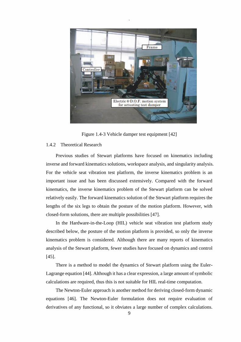
(3) Damper test equipment
Compared with a serial-link mechanism, the Stewart platform can maintain
uniformity in six directions with respect to frequency performance and rigidity. In [42],
a Stewart platform was used as universal damper test equipment. With this equipment,
test dampers can be installed in two directions for testing.
`
9
Figure 1.4-3 Vehicle damper test equipment [42]
1.4.2 Theoretical Research
Previous studies of Stewart platforms have focused on kinematics including
inverse and forward kinematics solutions, workspace analysis, and singularity analysis.
For the vehicle seat vibration test platform, the inverse kinematics problem is an
important issue and has been discussed extensively. Compared with the forward
kinematics, the inverse kinematics problem of the Stewart platform can be solved
relatively easily. The forward kinematics solution of the Stewart platform requires the
lengths of the six legs to obtain the posture of the motion platform. However, with
closed-form solutions, there are multiple possibilities [47].
In the Hardware-in-the-Loop (HIL) vehicle seat vibration test platform study
described below, the posture of the motion platform is provided, so only the inverse
kinematics problem is considered. Although there are many reports of kinematics
analysis of the Stewart platform, fewer studies have focused on dynamics and control
[45].
There is a method to model the dynamics of Stewart platform using the Euler-
Lagrange equation [44]. Although it has a clear expression, a large amount of symbolic
calculations are required, thus this is not suitable for HIL real-time computation.
The Newton-Euler approach is another method for deriving closed-form dynamic
equations [46]. The Newton-Euler formulation does not require evaluation of
derivatives of any functional, so it obviates a large number of complex calculations.

`
10
For the HIL vehicle seat vibration test platform study, a complete linear dynamic
model of motion platform using Newton-Euler method is suggested.
1.5 Hardware-In-The-Loop (HIL) System
The Hardware-in-the-Loop (HIL) system is extensively applied in engineering
R & D (Research and Development), especially for vehicle design, control tests, and
electronics systems [9]. Compare with a virtual prototyping simulation, HIL
simulation used both real physical and virtual system components. HIL techniques
play an important role in validating ideal models in an early development phase, and
for vehicular on-board devices testing, a HIL test approach is cheaper and more
efficient than a prototype vehicle test [15] [16].
Real-time control approaches can be divided into three categories, as shown in
Figure 1.5-1:
1. Control prototyping: Simulating and testing the controller during control of
the real process.
2. Software-in-the-loop (SIL): Using a virtual controller to control the virtual
prototype. This is usually used for design and feasibility verification of the
devices during the pre-exploitation period.
3. Hard-ware-in-the-loop (HIL): The simulated process can be controlled by a
real controller.
Figure 1.5-1 Classification of real-time control system

`
11
The first applications of the HIL system were for flight simulation, where the
early aim was to test the instruments using a cockpit, and then to control the cockpit
to simulate aircraft motions for pilot training [17]. The simulator uses a real cockpit
and motions generated by a platform [17] [18].
The HIL motion simulation platforms, with hydraulic or electrical actuators, were
designed for vehicle dynamic tests, such as suspension performance, ABS, and other
applications. One type of HIL simulation system is found in a driving simulator [19].
As digital control systems continue to develop, the HIL simulation system is
constantly being improved. The simulation models became more and more complex,
and computers were unable to meet the requirements for control speed. The application
of Field Programmable Gate Array (FPGA) technology allowed for real-time
simulation systems of a parallel mechanism system composed of sensors, actuators,
and suspensions. FPGA facilitated the further development of Programmable Array
Logic (PAL), Generic Array Logic (GAL) and programmable logic devices (PLD)
programmable devices. The logic functions are performed by an internal regular array
of logic cell arrays. Logic cell arrays are composed of three parts: a configurable logic
block, an input output block, and interconnection of these two units. Engineers can
reconfigure the internal logic module and IO module of the FPGA to achieve a desired
function. The advantages of PFGA include customized FIFO, hardware timer, high
reliability, and digital signal processing and analysis. These advantages provide a
flexible and low-cost solution for the vehicle electric testing technology.
FPGA can achieve splitting of closed-loop control loop rates on hardware level.
FPGA programming allows rapid response of the simulation to input signals. With the
parallelism of FPGA, multiple fast control loops can be integrated into one system.
For example, Drivven used the reconfigurable application performance of FPGA to
establish a Yamaha YZF-R6 engine control system and reduced costs by eliminating
the need to purchase custom hardware during the design process [48]. MicroNova also
uses the highly reliable and customizable logic functionality of FPGA hardware
platform in world's first V12 fuel engine hardware-in-loop simulation [49].
1.6 Research Objectives
Although the desirability of laboratory simulation is clear, there are significant
pitfalls. The loading conditions and practical limitations of the test rig hardware to

`
12
mimic external loading are not fully understood. Additionally, the capital cost of the
test equipment and control technology may be a limiting factor.
As technology develops, vehicle design and dynamical driving properties become
more complex. In driver seat vibration isolation studies, more research is devoted to
improvements of vehicle driving comfort and safety. However, current vibration
control of seat suspension study has been limited to simulations because the use of a
full-size vehicle would be expensive and dangerous. Currently, two methods can be
used for laboratory driver seat vibration testing. The first one is a physical system
where excitation signals are applied via four vertical actuators into the tyres of the
vehicle. However, this system suffers from high complexity and high cost.
Additionally, use of a particular vehicle as the laboratory simulation platform will
restrict the generalization of the findings. For example, different vibrations of the
vehicle may be detected due to the use of different damper or chassis structures on the
same road. In these kinds of systems, these components may be difficult to replace.
Therefore, this system can only simulate one kind of vehicle. Another method is a
virtual prototyping system. Although this method is highly reconfigurable, it can only
be used for virtual testing, meaning that it only can simulate vehicle dynamics on the
computer.
In this study, the goal is to find a better approach to combine the computer vehicle
vibration mathematical model and the Stewart platform together as a HIL system and
to control the platform to simulate the vibrations in a close approximation of real
vehicle movement dynamics. Especially for heavy-duty vehicles, the main range of
the chassis vibration frequency is from 0.5Hz to 5.0 Hz. Because the vibrations of off-
road vehicles occur in multiple directions, the vibration platform must possess a
sufficient degree of freedom to approximate the real vehicle vibrating situation. The
necessary problems to address are how to process the output data of mathematical
model and convert the data into the Stewart platform controller input data.
Additionally, it is necessary to determine the accuracy of the system when the
platform is in a heavy load situation, the maximum vibration frequency of the platform,
and the range of the platform movement.

`
13
1.7 Thesis Layout
This thesis is structured to provide a chapter-by-chapter view of the progressive
work done to achieve these research objectives. Chapter 2 focuses on the relevant
theories and simulations, including 7-DOF full car and Stewart platform modelling.
Chapter 3 outlines the experimental design and achievement. Chapter 4 details the
results of the experiment. Chapter 5 presents the conclusions and directions for future
work.

`
14
2 RELEVANT THEORY AND SIMULATION
In this section, the 7-DOF full-car model is used to study the response of the
vehicle to a bump road input. Furthermore, a mathematical model of the Stewart
platform is designed and inverse kinematics task is implemented in relation to the
model of the platform.
2.1 Full Car Model Analysis and Synthesis
2.1.1 7-DOF Full-car Model
The vehicle suspension fork is an important component as it connects the vehicle
body and axle and transmits the interaction forces and moments of the vehicle body
and wheel. The main function is to reduce the vibration and shock caused by uneven
surface, and to provide a comfortable and safe driving environment.
Many designs of a control system for a full car system used the well-known 7-
DOF model. In this study, we considered 3-DOF for the sprung mass and 4-DOF for
the front and rear unsprung masses for their vertical motion. A goal was to determine
a set of equivalent parameters that makes the simple model as close to the original
system as possible.
The full car model, which is shown in Figure 2.1-1, was used to approximate the
behaviour of a complete vehicle. The variables are defined as follows: The 𝑍𝑟1 ~ 𝑍𝑟4
are the road displacement inputs. It is assumed that the rear tires travel over the same
path as the front tires. Therefore, 𝑍𝑟2 is a delayed version of 𝑍𝑟1, 𝑍𝑟2 = 𝑍𝑟1(t − τ),
and 𝑍𝑟4 = 𝑍𝑟3(t − τ), where τ = v/( a + b), v is the forward vehicle speed, and
a + b is the vehicle wheelbase. The variables 𝑀𝑢1~ 𝑀𝑢4 are the under sprung mass
displacements. The four actuators placed between the sprung mass, Ms, and the
unsprung mass, 𝑀𝑢1~ 𝑀𝑢4, produce control forces 𝑢1 ~ 𝑢4. The variables 𝑍𝑢1 ~ 𝑍𝑢4
are the sprung mass displacements, 𝑍𝑠 is the centre of sprung mass displacement, θ is
the pitch angular displacement, and φ is the roll angular displacement. The tire stiffness
are denoted by 𝑘𝑢1 ~ 𝑘𝑢4 . The damping effect of the tires is negligible.
The 𝑘𝑠1~ 𝑘𝑠4 and 𝑐𝑠1 ~ 𝑐𝑠4 denote the stiffness and damping ratios of passive
suspension elements for the assemblies.

`
15
Figure 2.1-1 A 7-DOF full car model
The roll axis defined by the suspension kinematics is assumed to be horizontal.
The pitch axis is assumed to intersect the roll axis directly under the centre of the
sprung mass. The characteristics of all passive suspension elements are linear and the
equations of motion can be derived by application of Newton`s second law and its
simplification as Euler`s equation of motion for a rigid body as follows:
For the bouncing of the sprung mass:
MSZS = −(cs1 + cs2 + cs3 + cs4)Zs − (ks1 + ks2 + ks3 + ks4)Zs
− (−acs1 + bcs2 − acs3 + bcs4)θs
− (−aks1 + bks2 − aks3 + bks4)θs + cs1Zu1 + cs2Zu2
+ cs3Zu3 + cs4Zu4 + ks1Zu1 + ks2Zu2 + ks3Zu3
+ ks4Zu4 + u1 + u2 + u3 + u4
(1)
Pitching of the sprung mass:
𝐼𝑃��𝑆 = −(−𝑎𝑐𝑠1 + 𝑏𝑐𝑠2 − 𝑎𝑐𝑠3 + 𝑏𝑐𝑠4)��𝑠
− (−𝑎𝑘𝑠1 + 𝑏𝑘𝑠2 − 𝑎𝑘𝑠3 + 𝑏𝑘𝑠4)𝜃𝑠
− (𝑎2𝑐𝑠1 + 𝑏2𝑐𝑠2 + 𝑎2𝑐𝑠3 + 𝑏2𝑐𝑠4)��𝑠
− (𝑎2𝑘𝑠1 + 𝑏2𝑘𝑠2 + 𝑎2𝑘𝑠3 + 𝑏2𝑘𝑠4)𝜃𝑠 − 𝑎𝑐𝑠1��𝑢1
+ 𝑏𝑐𝑠2��𝑢2 − 𝑎𝑐𝑠3��𝑢3 + 𝑏𝑠4��𝑢4 − 𝑎𝑘𝑠1𝑍𝑢1 + 𝑏𝑘𝑠2𝑍𝑢2
− 𝑎𝑘𝑠3𝑍𝑢3 + 𝑏𝑘𝑠4𝑍𝑢4 − 𝑎𝑢1 + 𝑏𝑢2 − 𝑎𝑢3 + 𝑏𝑢4
(2)

`
16
Rolling of the sprung mass:
𝐼𝑟��𝑆 = −1
4(𝑡2
𝑓𝑐𝑠1 + 𝑡2𝑟𝑐𝑠2 + 𝑡2
𝑓𝑐𝑠3 + 𝑡2𝑟𝑐𝑠4)��𝑠
−1
4(𝑡2
𝑓𝑘𝑠1 + 𝑡2𝑟𝑘𝑠2 + 𝑡2
𝑓𝑘𝑠3 + 𝑡2𝑟𝑘𝑠4)𝜑𝑠
−1
2(−𝑡𝑓𝑐𝑠1��𝑢1−𝑡𝑟𝑐𝑠2��𝑢2 + 𝑡𝑓𝑎
2𝑐𝑠3��𝑢3 + 𝑡𝑟𝑐𝑠4��𝑢4)
−1
2(−𝑡𝑓𝑘𝑠1𝑍𝑢1−𝑡𝑟𝑘𝑠2𝑍𝑢2 + 𝑡𝑓𝑎
2𝑘𝑠3𝑍𝑢3 + 𝑡𝑟𝑘𝑠4𝑍𝑢4)
−1
2(−𝑡𝑓𝑢1−𝑡𝑟𝑢2 + 𝑡𝑓𝑢3 + 𝑡𝑟𝑢4)
(3)
Vertical direction for each wheel:
𝑀𝑢1��𝑢1 = −𝑐𝑠1Zu1 − (𝑘𝑢1 + 𝑘𝑠1)Zu1 + 𝑘𝑢1Zr1 + 𝑐𝑠1(Zs − aθs +
1
2𝑡𝑓φs)+ 𝑘𝑠1(Zs − 𝑎θs +
1
2𝑡𝑓φs)- 𝑢1
(4)
𝑀𝑢2��𝑢2 = −𝑐𝑠2Zu2 − (𝑘𝑢2 + 𝑘𝑠2)Zu2 + 𝑘𝑢2Zr2 + 𝑐𝑠2(Zs − aθs +
1
2𝑡𝑓φs)+ 𝑘𝑠2(Zs − 𝑎θs +
1
2𝑡𝑓φs)- 𝑢2
(5)
𝑀𝑢3��𝑢3 = −𝑐𝑠3Zu3 − (𝑘𝑢3 + 𝑘𝑠3)Zu3 + 𝑘𝑢3Zr3 + 𝑐𝑠3(Zs − aθs +
1
2𝑡𝑓φs)+ 𝑘𝑠3(Zs − 𝑎θs +
1
2𝑡𝑓φs)- 𝑢3
(6)
𝑀𝑢4��𝑢4 = −𝑐𝑠4Zu4 − (𝑘𝑢4 + 𝑘𝑠4)Zu4 + 𝑘𝑢4Zr4 + 𝑐𝑠4(Zs − aθs +
1
2𝑡𝑓φs)+ 𝑘𝑠4(Zs − 𝑎θs +
1
2𝑡𝑓φs)- 𝑢4
(7)
The system states are assigned as
𝑥1 = Zu1, vertical displacement of the left, front unsprung mass;
𝑥2 = Zu2, vertical displacement of the left, rear unsprung mass;
𝑥3 = Zu3, vertical displacement of the right, front unsprung mass;
𝑥4 = Zu4, vertical displacement of the right, rear unsprung mass;
𝑥5 = Zs, vertical displacement of the centre of gravity of sprung mass;
𝑥6 = θs, pitch of the sprung mass;
𝑥7 = φs, roll of the sprung mass;
Introducing the following state, the control input, and disturbance input vectors:

`
17
𝑥 = [𝑥1, 𝑥2, 𝑥3, ⋯ , 𝑥14]𝑇 (8)
𝑢 = [𝑢1, 𝑢2, 𝑢3, 𝑢4]𝑇 (9)
𝑤 = [Zr1, Zr2, Zr3, Zr4]𝑇 (10)
Defining 𝑥8 to 𝑥14 as the derivatives of 𝑥1 to 𝑥7, equations can be represented in the
form of the state equations:
�� = 𝐴𝑥 + 𝐵𝑢 + 𝐸𝑤 (11)
where A ∈ 𝑅14×14 is the system matrix; B ∈ 𝑅14×14 is the input matrix and E ∈
𝑅14×14 is the disturbance matrix.
Table 2.1-1 Car Parameters
Sprung mass (Ms) 2000kg
Unsprung mass (Mu1,Mu2) 150kg
Rear mass of the wheel (Mu3,Mu4) 150kg
Pitch of moment of inertia (Ip) 5800kg-m2
Roll of moment of inertia (Ir) 850 kg-m2
Stiffness of car body spring for front (ks1, ks3) 20000N/m
Stiffness of car body spring for rear (ks2, ks4) 17500N/m
Front width (tf), rear width(tr) 2000mm
Font and rear tire stiffness (ku1-ku4) 175000N/m
Front damping (cs1, cs3) 7000N
Rear damping (cs2, cs4) 4000N
Cockpit to front wheel (a) 1300mm
Cockpit to real wheel (b) 4000mm
The numerical data used for the pickup truck model simulation are given in Table
2.1-1.
For running stability and easy handling, the tyre deflection, which is proportional
to the dynamic tire-road contact force, should be small. In a full car model, all four
wheels are considered. Control forces are usually supplied by hydraulic actuators. It is

`
18
better to use lower power consumption for active control, so the control forces are also
considered in the performance index.
The design of a vehicle suspension involves a compromise among conflicting
goals. Optimizing ride comfort, suspension rattle space and road holding, the
performance index to be minimized can be written as follows:
𝐽 = lim1
2𝑇∫ [
1��𝑐
����
]
𝑇
𝑇
0
[
0000
0𝜌1
00
00𝜌2
0
000𝜌3
] [
1��𝑐
����
]
+ [
𝑠1
𝑠2𝑠3
𝑠4
]
𝑇
[
𝜌4
000
0𝜌5
00
00𝜌6
0
000𝜌7
] [
𝑠1
𝑠2𝑠3
𝑠4
]
+ [
𝑡1𝑡2𝑡3𝑡4
]
𝑇
[
𝜌8
000
0𝜌9
00
00
𝜌10
0
000
𝜌11
] [
𝑡1𝑡2𝑡3𝑡4
]
+ [
𝑢1
𝑢2𝑢3
𝑢4
]
𝑇
[
𝜌12
000
0𝜌13
00
00
𝜌14
0
000
𝜌15
] [
𝑢1
𝑢2𝑢3
𝑢4
]
(12)
where:
�� = ��5 = ��12 (13)
�� = ��6 = ��13 (14)
�� = ��7 = ��14 (15)
And:
𝑠1 = 𝑥5 − 𝑥1 +1
2𝑡𝑓𝑥7 − 𝑎𝑥6
(16)
𝑠2 = 𝑥5 − 𝑥2 +1
2𝑡𝑟𝑥7 + 𝑏𝑥6
(17)
𝑠3 = 𝑥5 − 𝑥3 −1
2𝑡𝑓𝑥7 − 𝑎𝑥6
(18)
𝑠4 = 𝑥5 − 𝑥4 −1
2𝑡𝑓𝑥7 + 𝑏𝑥6
(19)

`
19
𝑡1 = 𝑥1 − Zr1 (20)
𝑡2 = 𝑥2 − Zr2 (21)
𝑡3 = 𝑥3 − Zr3 (22)
𝑡4 = 𝑥4 − Zr4 (23)
where 𝜌1 ~ 𝜌15 are the weighting constants; several sets of weights can be used
depending on the conditions of motion, including velocity, road quality, vibration level
acceleration, or other factors. In addition, with regard to unit parameters that are used
in performance index (10), the values of weighting constants should be balanced. Two
more generally used sets are road holding and ride comfort, which will be considered
in this study. For expressing the performance index in a form that is quadratic in the
state and input vectors, it is required to substitute the acceleration ��, �� and �� (12).
Using (11) and (13) ~ (15) to have:
𝐽 = lim1
2𝑇∫ (𝑥𝑇𝑄1𝑥 + 2𝑥𝑇𝑁𝑢 + 𝑢𝑇𝑅𝑢𝑥 + 2𝑥𝑇𝑄12𝜔 + 𝜔𝑇𝑄2𝜔)
𝑇
0
𝑑𝑡 (24)
Where Q1, R and Q2 are symmetric, time-invariant weighting matrices and R is also
positive definite.
2.1.2 Full Vehicle Model Simulation Results
We used a 3.5cm × 38cm × 300cm bump to simulate a speed bump, as shown
in Figure 2.1-2.

`
20
Figure 2.1-2 Bump road model
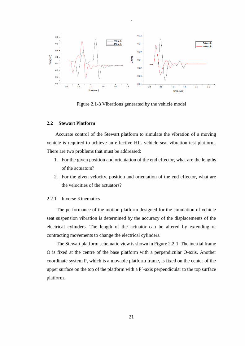
The vibrations of the vehicle when the vehicle passed the speed bump at 20km/h
and 40km/h are shown in Figure 2.1-3. Although the result is contrary to the instinct
that high speed usually leads to large vibration amplitude, the value of the stiffness of
car body spring and sprung mass effect the suspension performance. Therefore,
different vehicles may lead to different vibration amplitudes when passing the speed
bump at a same speed. Usually passing a speed bump at a high speed lead to a good
comfortable drive, however it may damage the suspension system.
The performance of the vehicle was affected by many factors including the
sprung mass and the stiffness of spring. Compared with the results when the vehicle
passed the speed bump at a high speed, the amplitude of vibration was smaller than at
a slow speed. However, the results can differ when the parameters of the vehicle model
are changed. This model enables testing and prediction of handling characteristics of
the physical prototype including vehicle chassis roll, ride comfort, ride safety and
suspension performance parameters. Road parameters such as surface conditions and
driving environment, which vary widely for real vehicle test, also can be controlled
conveniently for virtual vehicle test.
`
21
Figure 2.1-3 Vibrations generated by the vehicle model
2.2 Stewart Platform
Accurate control of the Stewart platform to simulate the vibration of a moving
vehicle is required to achieve an effective HIL vehicle seat vibration test platform.
There are two problems that must be addressed:
1. For the given position and orientation of the end effector, what are the lengths
of the actuators?
2. For the given velocity, position and orientation of the end effector, what are
the velocities of the actuators?
2.2.1 Inverse Kinematics
The performance of the motion platform designed for the simulation of vehicle
seat suspension vibration is determined by the accuracy of the displacements of the
electrical cylinders. The length of the actuator can be altered by extending or
contracting movements to change the electrical cylinders.
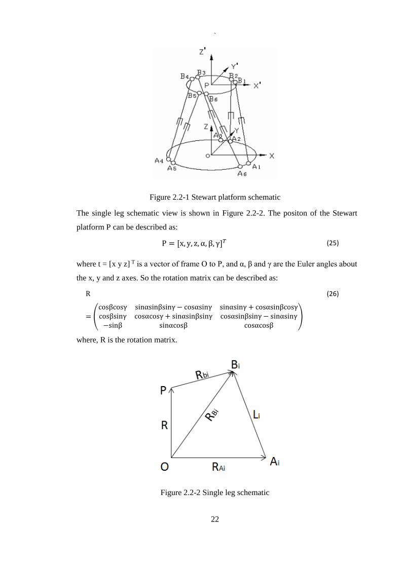
The Stewart platform schematic view is shown in Figure 2.2-1. The inertial frame
O is fixed at the centre of the base platform with a perpendicular O-axis. Another
coordinate system P, which is a movable platform frame, is fixed on the center of the
upper surface on the top of the platform with a P`-axis perpendicular to the top surface
platform.
`
22
Figure 2.2-1 Stewart platform schematic
The single leg schematic view is shown in Figure 2.2-2. The positon of the Stewart
platform P can be described as:
P = [x, y, z, α, β, γ]𝑇 (25)
where t = [x y z] T is a vector of frame O to P, and α, β and γ are the Euler angles about
the x, y and z axes. So the rotation matrix can be described as:
R
= (
cosβcosγ sinαsinβsinγ − cosαsinγ sinαsinγ + cosαsinβcosγcosβsinγ cosαcosγ + sinαsinβsinγ cosαsinβsinγ − sinαsinγ−sinβ sinαcosβ cosαcosβ
)
(26)
where, R is the rotation matrix.
Figure 2.2-2 Single leg schematic

`
23
First, the Coordinate System of the Stewart platform was built, as shown in Figure
2.2-1. P-X`Y`Z` designates the moving platform and O-XYZ is for the base platform.
When the moving platform is at the centre position, the X`Y `Z` coordinate axes are
in the same directions as XYZ. The coordinate point of the origin P of the coordinate
system P-X`Y`Z` is (xp, yp, zp), so the homogeneous transformation matrix is
𝑇 = [𝑅
𝑥𝑃
𝑦𝑃
𝑧𝑃
0 0 0 1
]
(27)
From the homogeneous transformation matrix, the coordinates of point Bi on the
coordinate system, P-X`Y`Z`, can be changed to O-XYZ. If the coordinates of point
Bi (i = 1… 6) are (XBi, YBi, ZBi), then:
[
𝑥𝐵𝑖
𝑦𝐵𝑖𝑧𝐵𝑖
1
] = 𝑇 [
𝑥`𝐵𝑖
𝑦`𝐵𝑖
𝑧`𝐵𝑖
1
] , 𝑖 = 1, 2 ,3 ,4 ,5 ,6
(28)
The length of the hinge point between the moving platform and base platform are
𝑙𝑖 = 𝐴𝑖𝐵𝑖 = √(𝑥𝐴𝑖 − 𝑥𝐵𝑖 )2 + (𝑦𝐴𝑖 − 𝑦𝐵𝑖 )2+(𝑧𝐴𝑖 − 𝑧𝐵𝑖 )2 ,
𝑖 = 1, 2, 3, 4, 5, 6
(29)
where 𝑙𝑖 is the leg length that can allow the top platform to reach the expected pose q.
The displacement that each electrical cylinder can extend is described as:
𝐷𝑖 = 𝑙𝑖 − 𝑙0, 𝑖 = 1, 2 ,3 ,4 ,5 ,6 (30)
where 𝑙0 is the leg length when the electrical cylinders are in the original position.
2.2.2 Platform Movement Speed Analysis
It can be seen from Figure 2.2-2 that if the unit vector ei is of the same direction as the
li; Rbi is the vector of the hinge point in the P-X`Y`Z`; and ωp, Vp are the angular

`
24
velocity and linear velocity vector at the origin P of the movable platform in coordinate
system O-XYZ.
Therefore, the velocity vector of point Bi is:
𝑉𝐵𝑖 = 𝜔𝑝 × 𝑅𝑏𝑖 + 𝑉𝑝 = [𝐼 −��𝑏𝑖] [𝑉𝑝
𝜔𝑝]
(31)
And the relative speed vi of the leg is:
𝑣𝑖 = 𝑒𝑖 ∙ 𝑉𝐵𝑖 = 𝑒𝑖 ∙ (𝜔𝑝 × 𝑅𝑏𝑖 + 𝑉𝑝) (32)
[𝑉𝑝
𝜔𝑝]𝑇
= [𝑉𝑝𝑥 𝑉𝑝𝑦 𝑉𝑝𝑧 𝜔𝑝𝑥 𝜔𝑝𝑦 𝜔𝑝𝑧]𝑇 (33)
Therefore,
V =
[ 𝑉1
𝑉2
𝑉3
𝑉4
𝑉5
𝑉6]
=
[ 𝑒𝑇
1 (𝑅𝑏1 × 𝑒1)𝑇
𝑒𝑇2 (𝑅𝑏1 × 𝑒2)
𝑇
𝑒𝑇3 (𝑅𝑏1 × 𝑒3)
𝑇
𝑒𝑇4 (𝑅𝑏1 × 𝑒4)
𝑇
𝑒𝑇5 (𝑅𝑏1 × 𝑒5)
𝑇
𝑒𝑇6 (𝑅𝑏1 × 𝑒6)
𝑇]
[𝑉𝑝
𝜔𝑝] = 𝐽𝑞
(34)
where J is the Jacobian matrix of the platform and q is velocity mapping from the P
point to each leg.
2.3 Summary
From the simulation result it can be seen that the 7-DOF car model can be used
to simulate the vibrations of the vehicle with bump road input. And according to the
mathematical models of the Stewart platform, the simulation results of the car model
can be used as inputs of the Stewart platform control. In the next chapter, a real Stewart
platform will be built and controlled as a vehicle seat test platform. The data, which is
from the 7-DOF car simulation, will be converted into the length of the six legs of the
real Stewart platform.

`
25
3 EXPERIMENTAL DESIGN
According to the results of the chapter 2, this section outlines the experimental
design. In the experiment, the hardware design, software design and control plan will
be presented individually. Because the output vibration data of the vehicle model in
last chapter is all about the absolute heave, pitch and roll velocities of the sprung mass,
in order to simulate the vibration in all dimensions, a Stewart multiple-DOF motion
platform will be designed to generate the required vibration.
3.1 Experimental Plan
Generally, laboratory road simulation applies to the reproduction of service loads
on complete vehicles in the laboratory. However, regarding the vehicle seat vibration
isolation study, it only focuses on the vibration of the vehicle chassis, and hence other
parts of the vehicle can be excluded. The vehicle vibration simulation platform consists
two parts. The structure of the system is shown in Figure 3.1-1.
Firstly, a linear 7-DOF full-car model will be built to study the response of the
vehicle with on-road and off-road inputs. The response is analysed by treating them as
input of the hardware part. And the response data will be used to calculate the length
of each actuator of the Stewart platform via LabVIEW. Finally, a Stewart platform
was designed to connect to the system and simulate the vibrations of the virtual
vehicle.
The output vibrations data of the vehicle model are related to the pitch, roll and
the displacements of sprung mass. In order to simulate the vibrations in all dimensions
and to gain a better control of the platform, a CompactRIO will be used to connect the
Stewart platform and the LabVIEW.
A well-defined Stewart platform in combination with a mathematical model of
the vehicle-road is used to replace the conventional vehicle test system. Different
vehicle-road mathematical model combinations can be easily simulated with a system
by changing the parameters of models. As a result, the mathematic simulation model
can be transformed into a real platform movement. The whole vibration simulator
platform becomes a hardware-in-the-loop (HIL) system.

`
26
Figure 3.1-1 Hardware-in-the-loop System Structure
3.2 Hardware Design and Control Plan
The hardware devices consist of the Stewart platform and the CompactRIO
control system. And in order to reduce the cost, only the cRIO-9076 modules are used.
3.2.1 The Stewart Platform
The 6-DOF Stewart platform consists of a fixed base platform, a movable top
platform and six linear actuators, which is shown in Figure 3.2-1 . Square steel tubes
are used to respectively fabricate the top and base platforms which are regular
hexagons with the lengths of sides 350mm and 500mm. Six electrical cylinders are
applied as actuators of motion platform, and they are connected the top and base
platform with spherical joints.

`
27
Figure 3.2-1 Stewart Platform Design
In general, Stewart platform can be driven by actuators and electrical cylinders or
hydraulic cylinders are the frequently used actuators. The actuator dynamics may be
neglected in many cases because of the fast time constants of electric cylinders.
However comparing with the electrical cylinders, hydraulic cylinders cannot
accurately apply torques over a great dynamic range. The dynamics of hydraulic
system are highly nonlinear because of the fluid compressibility or the characteristics
of nonlinear servo valve flow pressure.
Figure 3.2-2 shows the real Stewart platform. The six electric cylinders (actuators)
of the platform are respectively driven by six AC servo drivers.

`
28
Figure 3.2-2 Stewart platform hardware structure
The electric cylinder consists of two parts: the telescopic actuator and AC servo
motor. The parameters of the servo motor are shown in Table 3.2-1. Because the servo
motor uses the rotating dynamics to drive the telescopic actuator to move, and by
changing the length of the actuator, the servo motor operation must be operated by
dedicated servo drive. Therefore, six servo motor drives respectively drive the six
servo motors to operate. The servo motor drivers are shown in Figure 3.2-3. And the
parameters of the motor driver are shown in Table 3.2-2.
Table 3.2-1 Servo Motor Parameters
Model 80MB-R7530A23F-0MF2
Input 4.4A
Rated Output: 0.75KW
Rated Rev 3000rpm

`
29
Figure 3.2-3 Servo motor drivers
The position control mode is used to control the servo motor in order to ensure
the motion accuracy of the platform. The position control is based on the positional
command (pulse train) from the host controller (cRIO-9076).
There are two input signals that must be set before sending the control commands
to a servo driver, which is shown in Figure 3.2-4. The input 1 is pulse train, the
frequency of the pulse determines the rotational speed of the motor. And the input 2 is
directional control signal.
Figure 3.2-4 Pulse train and sign mode
For example, in the case if sending 2000 pulse signals to the servo motor drive,
the servo motor can be rotated 360°, and the actuator can elongate or shorten 4mm,
and rotate. The rotational speed of motors depends on the frequency of the pulse signal.

`
30
In order to ensure the reliability of the signal transmission, the input signals are all
differential signal. Therefore AM26C32 ICs are used to convert the TTL signals into
differential signals, which is shown in Figure 3.2-5.
Figure 3.2-5 Convert TTL signal to differential signal
Table 3.2-2 AC Motor Driver Parameters
Model DMKE LS-022-H33B-M-B
Source 3PH AC380V 50/60HZ
Output 22KW 45A 0-9000rpm
In order to well control the platform, each servo motor has an encoder to feedback
the movement position of current electric cylinder. The feedback is a differential signal,
through the differential signal to TTL signal converter module, which is shown in
Figure 3.2-6, to convert the signals into TTL signals, and then the signals can be
received by the host controller.

`
31
Figure 3.2-6 Differential signal to TTL signal converters
3.2.2 National Instruments (NI) CompactRIO (cRIO) Control System
National Instruments CompactRIO is compatible with LabVIEW graphical
programming language. LabVIEW is a user friendly software package for rapid and
convenient development of complex measurement and control systems. Additionally,
CompactRIO modules are less expensive with a wide variety of features. In this case,
the model used in the CompactRIO is cRIO-9076, which is shown in Figure 3.2-7.
Figure 3.2-7 NI CompactRIO control system

`
32
The cRIO-9076 combines a real-time processor and a reconfigurable FPGA for
embedded system control and measuring applications. It integrates a 400 MHz
industrial real-time processor with an LX45 FPGA and has four slots for I/O modules
[51].
There are four NI 9401 modules used as input/output interface ports. The NI 9401
is an 8-channel 100ns bidirectional digital module. And with reconfigurable I/O
technology, it is easily to be used via the LabVIEW FPGA for I/O control, pulse
generation. Each channel is compatible with 5V/TTL signals and features 1000 Vrms
transient isolation between the I/O channels and the backplane [51].
3.3 Software Design and Control System Design
In order to control the Stewart platform to simulate the vibrations of the virtual
vehicle, there are 3 steps should be considered:
1. Send the vibrations data to the CompactRIO host controller.
2. Convert the vibrations data to the lengths of the actuators and the movement
speed in the CompactRIO FPGA.
3. Convert the length and motion speed data to the control signals to the servo
drivers to control the actuators via IO port of the NI-9401 module.
After that, servo motors will drive the actuator to move, and the platform can generate
the same vibrations according to the computer model.
3.3.1 LabVIEW VI Design
Most controllers are serial systems; they only sent one control command at a time.
When the first control command is executed, the next control command task can be
processed. However, for controlling a parallel mechanism, like Stewart platform, serial
system is unsuitable. Using FPGA can resolve this problem, because the FPGA can
send all of the control commands at the same time.
The CompactRIO controller includes a processor and reconfigurable FPGA. With
the user-programmable FPGA, it can implement the hardware high-speed control, and
data processing. The six linear actuators of the platform must be controlled at the same
time. Moreover, there are six high resolution encoders sending the signal back to the
CompactRIO. Thus, the controller and data processing are all programmed in FPGA
module, which is shown in Figure 3.3-1.

`
33
Figure 3.3-1 LabVIEW VI structure
The real-time layer is used to build the human-computer interface and monitor
operational status.
3.4 Summery
This section presented the details of the HIL driver seat vibration test platform,
including the real Stewart platform design, the system structure and the real Stewart
platform controlled via the LabVIEW FPGA. In the next section, the HIL driver seat
test platform will be used to simulate the vehicle seat vibrations with on-road and off-
road inputs, and then the output data of the system will be analysed.

`
34
4 THE EXPERIMENTAL RESULTS AND DISCUSSION
In this section, the HIL system with varying road inputs will be used to simulate
the real vehicle vibration. The simulation results and the real Stewart platform results
will be compared and analysed. Moreover, the performance of the platform will be
discussed.
4.1 Simulation Results
When a sine sweep road signal, which is shown in Figure 4.1-1, was set as the
input of the virtual prototyping vehicle model, and set the speed of the vehicle model
to 20 km/h, the vehicle chassis mostly produces 2-DOF vibration, pitch and vertical
acceleration. It can be seen from the Figure 4.1-2 that the value of the pitch acceleration
decreased to the resonance point and then increased gradually.
Figure 4.1-1 Sine sweep road model
Figure 4.1-2 Pitch acceleration generated by the vehicle model
`
35
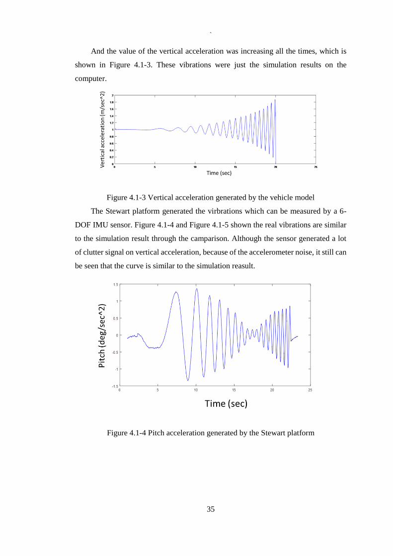
And the value of the vertical acceleration was increasing all the times, which is
shown in Figure 4.1-3. These vibrations were just the simulation results on the
computer.
Figure 4.1-3 Vertical acceleration generated by the vehicle model
The Stewart platform generated the virbrations which can be measured by a 6-
DOF IMU sensor. Figure 4.1-4 and Figure 4.1-5 shown the real vibrations are similar
to the simulation result through the camparison. Although the sensor generated a lot
of clutter signal on vertical acceleration, because of the accelerometer noise, it still can
be seen that the curve is similar to the simulation reasult.
Figure 4.1-4 Pitch acceleration generated by the Stewart platform

`
36
Figure 4.1-5 Vertical acceleration generated by the Stewart platform
When the car model is running on the off-road at the same speed, the simulation result
can be seen from the Figure 4.1-6 and the Figure 4.1-7.
Figure 4.1-6 Pitch acceleration generated by the vehicle model

`
37
Figure 4.1-7 Vertical acceleration generated by the vehicle model
The real vibrations which generated by the Stewart platform is shown in Figure 4.1-8
and Figure 4.1-9. With comparison of the simulation results, the actual data match the
simulation result.
Figure 4.1-8 Pitch acceleration generated by the Stewart platform

`
38
Figure 4.1-9 Vertical acceleration generated by the Stewart platform
It means the Stewart platform can generate the corresponding vibrations according to
the input data (vehicle model simulation result). In other words, whether the Stewart
platform can accurately simulate the vibrations of the vehicles, it not only depends on
the quality of the control system, but also depends on the accuracy of the vehicle model
simulation.
4.2 Loading Platform Load Reactions and Load Capacities
Whether the platform is able to meet the need of seat testing to generate the
required vibrations in the situation of heavy load is an important problem.
Figure 4.2-1 In the process of seat testing
In the process of seat testing, which is shown in Figure 4.2-1, the weight of the
seats and human were within 100 kg. After with 100 kg loading and given 1 Hz, 7 mm

`
39
amplitude of sin signal as input, the vibration (encoder output) of the platform and
input signal were overlapping, which is shown in Figure 4.2-2.
Figure 4.2-2 Results of the loading platform comparing
When the input signal changed into 5 HZ, 2mm sin signal, and the results can be
seen in Figure 4.2-3, the curves were still overlapping.
Figure 4.2-3 Results of the loading platform comparing with 5 HZ and 2 mm sine
signal input
However, increase the values of the sine input signal to the 7 Hz 3 mm, it can be
seen from the Figure 4.2-4, the two curves were not overlapping. And the vibration
generated by the platform was lag behind the input signal.

`
40
Figure 4.2-4 Results of the loading platform comparing with 7 HZ and 3 mm sin
signal input
The weight of the loading has a great influence on the performance of the platform.
That is because the electric cylinders of the platform had exceeded the rated power.
Figure 4.2-5 Comparison of the input signal and output result in frequency domain
Although the result lagged behand the input signal in the frequency domain, which is
shown in Figure 4.2-5, the frequencies were the same. However, the amplitude of the
vibration generated by the platform was slightly lower than the input signal.

`
41
5 CONCLUSIONS AND RECOMMENDATIONS
This thesis has aimed to build a vehicle seat vibration test platform, and the
purpose was to test the seat vibration damping performance in the seat vibration
research as well as to reduce the development costs and achieve better research data.
The experiment and results proved the platform can generate the required vibrations,
and the vibrations were in accordance with the vehicle mathematical model simulation
results.
The cRIO host controller can well control the movement of the Stewart platform.
Moreover, the complex code programming was replaced by clear and understandable
graphical programming via the LabVIEW. The six electric cylinders can be controlled
at the same time in the FPGA layer, therefore accuracy of the parallel mechanism can
be guaranteed.
The quality of building a vehicle model is one of the key factors to accurately
simulate the vibrations of vehicle in the platform. Although in this thesis, a simple 7-
DOF vehicle mathematical model is built for simulation, from the obtained results it
can be seen, vibrations generated by the platform were closer to the vibration generated
by the vehicle simulation. And higher accuracy of vehicle model, like 11-DOF or more,
also can make the results of the platform closer to the real vehicle. Moreover, via
changing the parameters of the vehicle mathematical model, the system can be used
for testing the seat damping performance on different vehicles. Therefore, it can
greatly reduce the difficulty of seat testing. Furthermore, the platform has six degrees
of freedom, so there is a lot of room for further improvements to meet the requirement
of vehicle seat test.
The load weight of the test platform design is 90 kg, and in the case of 90 kg load
the running accuracy of the platform can be guaranteed. If an excessive load was
applied, the frequency of the vibrations was unchanged, however, the amplitude was
reduced. Because the performance of the platform is restricted by the servo motor, high
power servo motors can provide a better platform motion performance. If the seat test
requires the load of the platform larger than 90kg, bigger power servo motors must be
used.
With these milestones completed, this work contributes to provide an ideal test
environment for the vehicle seat test:

`
42
Combine the computer vehicle vibration mathematical model and the Stewart
platform together to control the platform to simulate the vibrations in a close
approximation of real vehicle movement dynamics as well as improved the
vehicle seat testing environment.
The platform expansibility can adapt to the requirement of the seat test and at
the same time to reduce the time and cost of the vehicle seat testing.
With the goals achieved, and the results obtained, several avenues exist for future work.
Improve the accuracy of the vehicle mathematical model, so that the platform
can generate vibrations more closely to the actual vehicle vibrations in different
degrees of freedom.
On the real-time layer, the human-machine interface will continue to be
improved, for example achieve real-time switching to a different vibration.
Achieve the human-in-the loop test by improving the safety of the platform.
More over through monitoring the temperature of the hardware devices,
therefore the safety of the platform can be increased in continuous heavy load
operation.
`
43
REFERENCES
[1] Mabbott, Nick, Gary Foster, and Barbara McPhee. Heavy vehicle seat vibration
and driver fatigue. No. CR 203. 2001
[2] Otto, Norman C., William J. Pielemeier, and Raymond C. Meier Jr. "Vehicle
vibration simulator." U.S. Patent No. 5,618,995. 8 Apr. 1997.
[3] Matthews, J. "Ride comfort for tractor operators: IV. Assessment of the ride quality
of seats." Journal of Agricultural Engineering Research 11.1 (1966): 44-57.
[4] Els, P. S. "The applicability of ride comfort standards to off-road vehicles." Journal
of Terramechanics 42.1 (2005): 47-64.
[5] Gough, V. E., and S. G. Whitehall. "Universal tyre test machine." Proc. FISITA
9th Int. Technical Congress. 1962.
[6] Moog, W. C. "A general summary report on the development of a family of electro-
hydraulic servo valves for the bumblebee guidance system." CAL/CF-1371,
Cornell Aeronautical Laboratory, Inc (1949).
[7] Hodkin, R. K. "Hydraulic Vibrators in Automobile Testing with Special Reference
to the Rootes Suspension Parameter Rig." Proceedings of the Institution of
Mechanical Engineers 182 (1967).
[8] Betz, Edward R. Studying Structure Dynamics with the Cadillac Road Simulator.
No. 660101. SAE Technical Paper, 1966.
[9] Cripe, Ronald A. Making a road simulator simulate. No. 720095. SAE Technical
Paper, 1972.
[10] Engels, F. "Vibrations in vehicles and methods of investigating them."
Instrumentation and Test Techniques for Motor Vehicles. A Symposium
Sponsored by the IME and the Advanced School of Automobile Engineering.
1967.
[11] Dodds, Colin J. "The laboratory simulation of vehicle service stress." Journal of
Engineering for Industry 96.2 (1974): 391-398.
[12] Stein, G. J., and I. Ballo. "Active vibration control system for the driver's seat for
off-road vehicles." Vehicle System Dynamics 20.2 (1991): 57-78.
[13] Le, Thanh Danh, and Kyoung Kwan Ahn. "A vibration isolation system in low
frequency excitation region using negative stiffness structure for vehicle seat."
Journal of Sound and Vibration 330.26 (2011): 6311-6335.
[14] Lu, Bin. The real-time extension of the virtual test bed: A multi-solver hard real-
time hardware-in-the-loop simulation environment. 2003.

`
44
[15] Wu, Jian, and Noel N. Schulz. "Experimental design for remote hardware-in-the-
loop testing." Proceedings of ASNE Reconfiguration and Survivability
Symposium. 2005.
[16] Palla, Sunil, Anurag K. Srivastava, and Noel N. Schulz. "Hardware in the loop test
for relay model validation." Electric Ship Technologies Symposium, 2007.
ESTS'07. IEEE. IEEE, 2007.
[17] Isermann, R., J. Schaffnit, and S. Sinsel. "Hardware-in-the-loop simulation for the
design and testing of engine-control systems." Control Engineering Practice 7.5
(1999): 643-653.
[18] Anderson, O. K. A Design Tool (Research and Development) Simulator Survey
Report. No. 620310. SAE Technical Paper, 1962.
[19] Drosdol, J., W. KADING, and F. Panik. "The daimler-benz driving simulator."
Vehicle System Dynamics 14.1-3 (1985): 86-90.
[20] DeGroat, Douglas E., and Patricia M. McKenna. "Vehicle vibration simulator and
method for programming and using same." U.S. Patent No. 5,277,584. 11 Jan.
1994.
[21] Huang, Andy RW, and Chihsiuh Chen. "A low-cost driving simulator for full
vehicle dynamics simulation." Vehicular Technology, IEEE Transactions on52.1
(2003): 162-172.
[22] Huang, Guoshing, and Shuocheng Lee. "PC-based PID speed control in DC
motor." Audio, Language and Image Processing, 2008. ICALIP 2008.
International Conference on. IEEE, 2008.
[23] Zhu, S. J., Y. F. Zheng, and Y. M. Fu. "Analysis of non-linear dynamics of a two-
degree-of-freedom vibration system with non-linear damping and non-linear
spring." Journal of Sound and Vibration 271.1 (2004): 15-24.
[24] Tadokoro, Satoshi, et al. "A motion base with 6-DOF by parallel cable drive
architecture." Mechatronics, IEEE/ASME Transactions on 7.2 (2002): 115-123.
[25] Hostens, I., Jan Anthonis, and Herman Ramon. "New design for a 6 dof vibration
simulator with improved reliability and performance." Mechanical systems and
signal processing 19.1 (2005): 105-122.
[26] Katzourakis, Diomidis, et al. "Steering force feedback for human–machine-
interface automotive experiments." Instrumentation and Measurement, IEEE
Transactions on 60.1 (2011): 32-43.
[27] Kawamura, Sadao, et al. "Development of a virtual sports machine using a wire
drive system-a trial of virtual tennis." Intelligent Robots and Systems 95.'Human
Robot Interaction and Cooperative Robots', Proceedings. 1995 IEEE/RSJ
International Conference on. Vol. 1. IEEE, 1995.

`
45
[28] Rouillard, Vincent. "The synthesis of road vehicle vibrations based on the
statistical distribution of segment lengths." (2007): 614.
[29] Conrad, Leanne F., et al. "Selecting seats for steel industry mobile machines based
on seat effective amplitude transmissibility and comfort." Work (Reading, Mass.)
47.1 (2013): 123-136.
[30] Yun, Yuan, and Yangmin Li. "A general dynamics and control model of a class of
multi-DOF manipulators for active vibration control." Mechanism and machine
theory 46.10 (2011): 1549-1574.
[31] Tseng, Hung‐Lung, and I. Fong. "Implementation of a driving simulator based
on a stewart platform and computer graphics technologies." Asian Journal of
Control 2.2 (2000): 88-100.
[32] Su, Yu Xin, and Bao Yan Duan. "The application of the Stewart platform in large
spherical radio telescopes." Journal of Robotic Systems 17.7 (2000): 375-383.
[33] Lebret, Guy, Kai Liu, and Frank L. Lewis. "Dynamic analysis and control of a
Stewart platform manipulator." Journal of Robotic systems 10.5 (1993): 629-655.
[34] Preumont, André, et al. "A six-axis single-stage active vibration isolator based on
Stewart platform." Journal of sound and vibration 300.3 (2007): 644-661.
[35] Stewart, Doug. "A platform with six degrees of freedom." Proceedings of the
institution of mechanical engineers 180.1 (1965): 371-386.
[36] Gough, V. E., and S. G. Whitehall. "Universal tyre test machine." Proc. FISITA
9th Int. Technical Congress. 1962.
[37] Behi, Fariborz. "Kinematic analysis for a six-degree-of-freedom 3-PRPS parallel
mechanism." Robotics and Automation, IEEE Journal of 4.5 (1988): 561-565.
[38] Hudgens, J. C., and D. Tesar. "A fully-parallel six degree-of-freedom
micromanipulator: kinematic analysis and dynamic model." Proc. 20th Biennial
ASME Mechanisms Conf. Vol. 15. 1988.
[39] Geng, Z. Jason, and Leonard S. Haynes. "Six degree-of-freedom active vibration
control using the Stewart platforms." Control Systems Technology, IEEE
Transactions on 2.1 (1994): 45-53.
[40] Jafari, Farhad, and John E. McInroy. "Orthogonal Gough-Stewart platforms for
micromanipulation." Robotics and Automation, IEEE Transactions on 19.4
(2003): 595-603.
[41] Barale, S., et al. "Comfort analyses of the Hydractive suspension using a driving
simulator." in Driving Simulator Conference, Paris, France. 2014.
[42] WATANABE, Nobuyuki, et al. "Development of oil damper test equipment
capable of simulating the actual conditions of railway vehicles." Quarterly Report
of RTRI 49.1 (2008): 1-6.

`
46
[43] Nanua, Prabjot, Kenneth J. Waldron, and Vasudeva Murthy. "Direct kinematic
solution of a Stewart platform." Robotics and Automation, IEEE Transactions on
6.4 (1990): 438-444.
[44] Lebret, Guy, Kai Liu, and Frank L. Lewis. "Dynamic analysis and control of a
Stewart platform manipulator." Journal of Robotic systems 10.5 (1993): 629-655.
[45] Dasgupta, Bhaskar, and T. S. Mruthyunjaya. "The Stewart platform manipulator:
a review." Mechanism and machine theory 35.1 (2000): 15-40.
[46] Dasgupta, Bhaskar, and T. S. Mruthyunjaya. "Closed-form dynamic equations of
the general Stewart platform through the Newton–Euler approach." Mechanism
and machine theory 33.7 (1998): 993-1012.
[47] Chen, Sung-Hua, and Li-Chen Fu. "Output feedback sliding mode control for a
Stewart platform with a nonlinear observer-based forward kinematics solution."
Control Systems Technology, IEEE Transactions on 21.1 (2013): 176-185.
[48] Dase, Carroll, Jeannie Sullivan Falcon, and Brian MacCleery. "Motorcycle control
prototyping using an FPGA-based embedded control system." Control Systems,
IEEE 26.5 (2006): 17-21.
[49] Schlüter, Wolfgang, Franz Dengler, and Consumer Goods. "HIL Test Systems for
the BMW Hydrogen 7."
[50] Kim, Chul, and Paul I. Ro. "An accurate full car ride model using model reducing
techniques." Journal of mechanical design 124.4 (2002): 697-705.
[51] Website: http://www.ni.com/en-au.html

`
47
APPENDIX A: THE LABVIEW VI PROGRAM

`
48
Structure of project:

`
49
InverseKinematics.vi:

`
50
GenerateWaveForm.vi:

`
51
FPGA_M_Mode.vi:

`
52
FPGA_Leg_Driver.vi:

`
53
Encoder signal receive processing:

`
54
FPGA_Pluses_Timer.vi:

`
55
RealTime_Main.vi:

`
56
RealTime_Main.vi (front panel):

`
57
Fast Fourier transform Matlab code:
Fs = 128; % sampling frequency
T = 1/Fs; % sampling time
L = 256; % Signal length
t = (0:L-1)*T; % Time
N = 2^nextpow2(L); % Sampling points
f = Fs/N*(0:1:N-1); % Frequency
Yi = fft(input,N)/N*2;
Ai = abs(Yi);
Yo = fft(output,N)/N*2;
Ao = abs(Yo);
figure;
subplot(211);
plot(t,input);hold on;
plot(t,output);
title('Input and Output Signal')
xlabel('Time(s)')
ylabel('Amount of pulse')
subplot(212);
plot(f(1:N/2),Ai(1:N/2)); hold on;
plot(f(1:N/2),Ao(1:N/2));
title('FFT Spectrum')
xlabel('Frequency(Hz)')
ylabel('Amplitude ')


![Motion Planning for High-DOF Manipulation Using ...gamma.cs.unc.edu/HSI/ICRA19_2159_FI.pdfHigh-DOF Robot Systems are used in various appli-cations such as soft robots [22]. A popular](https://img.pdfslide.us/doc/110x75/5f607485cae1322a304c6ccd/motion-planning-for-high-dof-manipulation-using-gammacsunceduhsiicra192159fipdf.jpg)