Embed Size (px)
Citation preview

FLOORINGTECHNICAL MANUAL
National Precast Concrete Association Australia

Hollowcore units are machine-made in afactory. They are nominally 1200 mmwide, range in thickness from 150 mm to400 mm and come with a variety of coreconfigurations depending on the type ofproduction equipment
Hollowcore Floor Planksfeature:
■ Speed of construction
■ Immediate work platform
■ Elimination of formwork orpropping
■ Reduction of on-site labour
Hollowcore Floor Planks, as a structural unit:
■ Are lightweight and efficient ■ Are durable
■ Allow design flexibility ■ Allow long spans
■ Have high load capacity
Hollowcore Floor Planks, as a floor system, provide:
■ Required fire ratings ■ Accommodation of services
■ Sound insulation ■ Flexible ceiling options
■ Complete package (manufacture, delivery and installation)
FLOORINGTECHNICAL MANUAL
CONTENTS
1 Introduction 2
2 Design Approach 3
3 Pre-planning 4
4 Preliminary Design 5
5 Final Design 8
6 Construction 16
7 Guide Specification 22
8 Bibliography 24
9 Sample Calculation 25
Published July 2003
ISBN 0 9577467 2 5
© 2003National Precast Concrete Association Australia.
All rights reserved. Except where the Copyright Act allowsotherwise, no part of this publication may be reproduced,stored in a retrieval system, or transmitted in any form,or by any means, electronic, mechanical, photocopying,recording or otherwise without the prior written permissionof the National Precast Concrete Association Australia.
Since the information provided in this publication isintended for guidance only and in no way replaces theservices of professional consultants on particular projects,no legal liability can be accepted by the National PrecastConcrete Association Australia.
For manufacturers and other information on hollowcore,see the NPCAA web site: www.npcaa.com.au.
1 INTRODUCTION
Hollowcore floor planks are precast, prestressedelements produced on a long-line bed using anextrusion or slide-forming machine. Planks arenormally 1200 mm wide, thicknesses range from150 mm to 400 mm and cores vary in shape, sizeand number depending on the equipment used formanufacture. Hollowcore floor units are referred toas planks, panels or slabs interchangeably, the firstterm has been adopted in this Manual todistinguish them from wall panels in a companionmanual.
The casting bed lengths are generally between120 m to 170 m and made of steel. The beds areusually heated from underneath to shorten thecuring cycle and ensure daily production. Theplanks are saw-cut on the bed to the requiredlengths.
A thin topping of concrete is often placed on-site toproduce composite units and a level floor surface,but the planks can just as readily be used withgrouted joints only.
Hollowcore planks, as a flooring system, havemany of the advantages of precast products ingeneral as well as some unique to themselves.
■ Machine-Made in Factory Hollowcore floorplanks are manufactured by machine in afactory, cured, cut to length and stored ahead ofthe construction schedule, ready for immediatedelivery to the project.
■ Speed of Construction They are rapidlyinstalled with minimal equipment and labour,thus reducing construction time. The resultingtime saving reduces risk, site costs and financialcharges.
■ Immediate Work Platform They provide animmediate and safe working platform forfollowing trades. They can be designed toaccommodate high construction loads withoutpropping
■ Eliminates Formwork or Propping Hollowcoreplanks do not require propping duringconstruction. Clear and unrestricted access isimmediately available to following trades.
■ Reduced On-Site Labour A small erectioncrew can install up to 1,000 m2 of hollowcorefloor planks per day.
■ Efficient, Lightweight Section The hollowvoids and prestressing result in reduced deadload for a given strength. The depth of plankand the strand pattern can be varied atminimum cost to suit the span and loadrequirements.
■ Design Flexibility Hollowcore floor planks canbe used in combination with most buildingmaterials including masonry walls, precast orinsitu concrete walls and beams, prestressedconcrete or steel beams. Hollowcore planks canaccommodate most building requirementsincluding openings, angles and cantilevers.
■ Durability Concrete used for the production ofhollowcore meets the durability requirements ofthe Australian Standard AS 3600. Strand covermay be varied to suit particular exposureconditions.
■ Long Span Hollowcore planks canaccommodate long spans, resulting in column-free open space. Clear spans of up to 20 metrescan be economically achieved.
■ High Load Capacity Hollowcore planks arecapable of handling the heavy loads required inshopping centres, car parks, offices,apartments, housing and warehouse structuresat minimal floor depths. Some sections are ableto be used as bridge members.
■ Fire Resistance Fire resistance levels up tothe regulatory maximum of 240/240/240 can beprovided.
■ Sound Insulation Hollowcore floors reducethe amount of transmitted noise. Rw+Ctr andLn,w+C1 ratings, as specified in building codes,can be met for a variety of occupancyrequirements.
■ Pre-Finished Ceilings Hollowcore planksprovide flat soffits, which will readily acceptpainted or applied textured finishes.Alternatively, the soffits can be directly lined inplasterboard or have a suspended ceiling.
■ Services The cores in the planks can be usedas service ducts to conceal plumbing, electricaland telephone cables. Large openings arepre-cut by the manufacturer during productionwhilst small penetrations are cut or cored onsite.
■ Complete Package Hollowcore floor planks canbe manufactured, delivered and installed on siteby the manufacturer as a complete package.
2

2 DESIGN APPROACH
The design of a hollowcore floor is usuallyundertaken in two stages:
■ Preliminary Design The general layout, theoverall dimensions of the planks and the typicaldetails are selected to suit the buildingrequirements, and
■ Final Design The details of the planks such asstrand patterns, connections, embedded itemsare decided and the shop drawings produced.
It is normal for the manufacturer to participate inthe design process with the project managementteam as well as providing advice on costing. Thecapacity to participate varies with eachmanufacturer and from job to job. Theresponsibilities are generally divided as follows.
The project management team, which includes theArchitect and Structural Engineer, usually providesthe following:
■ The general arrangement drawings showing thefloor plan layout, building dimensions andgeneral structure and support methods.
■ The project specification.
■ The codes and particular building regulationsgoverning the project.
■ The vertical and horizontal loadings on the floor.
■ The required fire resistance levels.
■ The noise insulation requirements.
■ The vibration characteristics if required.
■ Any deflection restrictions.
■ Forces arising from structural frame actions.
■ Checking and acceptance of the designcalculations when the manufacturer carriesthese out.
■ Overall responsibility for the structural design ofall elements in the project including theintegration of the hollowcore planks into thestructure.
The manufacturer usually provides the following:
■ Detailed specification for the manufacture of theplanks using proprietary equipment.
■ The detailed design of the hollowcore planks asagreed.
■ Detailed layout drawings locating each planktype in the structure.
■ Support and joint details.
■ Product drawings showing plank detailsincluding dimensions and the location of liftingand fixing inserts.
■ The erection procedure.
The structural design of the planks may beprovided by either party, depending on thecontractual arrangements:
■ If carried out by the Structural Engineer, themanufacturer supplies design properties uniqueto his product, such as section properties,normal concrete strengths, strand patterns.
■ If carried out by the manufacturer all designdocumentation is provided to the StructuralEngineer who checks that the design meets theproject requirements in all respects.
3
3 PRE-PLANNING
In planning a structure considerable benefits areachieved by establishing a framing layout to suitthe hollowcore module and span capability, ratherthan substituting hollowcore for a traditional insituconcrete layout. The most economical grid in aframed structure maximises the span of thehollowcore and minimises the span of the supportbeams. Most buildings have at least one short grid(usually 7.2 to 8.4 m) which can be used as thebeam span and then the span of the planks follow.
The primary consideration in developing a framingplan is the span length. For a given loading, firerating and exposure classification, the span lengthand the plank thickness can be optimised using amanufacturer’s published load tables as a guide.
It is strongly recommended that a manufacturer beconsulted during the preliminary stages of aproject so that advice can be provided on the mostcost-effective and practical design.
Floor Depth
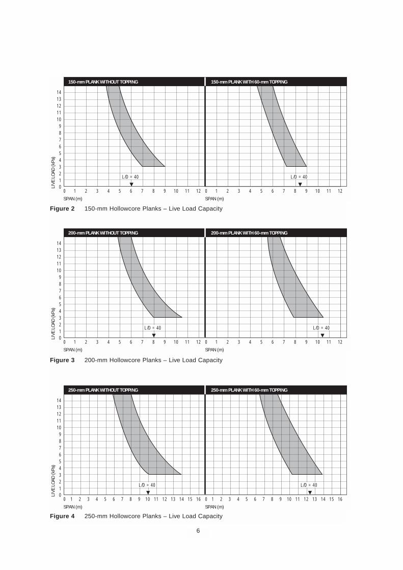
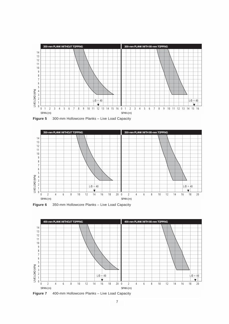
For preliminary design the general load-spangraphs in Figures 2 to 7 can be used to determinea suitable plank depth. To limit the deflection of afloor slab and its sensitivity to vibration, the ratio ofspan to overall depth is usually kept in the range of30–35 but can be up to 40. Roof slabs which arenot subject to foot traffic can range from 35–45.For handling, the ratio should not exceed 45.
The slab thickness may need to be increased ifdeflection and vibration are critical such as whenthere are sustained live loads, rhythmic action,masonry partitions or a large number of openings.Slender planks subject to light repetitive loadingsuch as foot traffic in quiet environments should bechecked for perceptible vibration. High fire ratingsincrease cover and may require an increase inoverall depth. It is not practical to use continuity inthe structure to minimise plank depth.
Plank Width
It is preferable that the floor plan dimensions suit a1200-mm module width. Never the less, non-modular dimensions can be accommodated withlongitudinally-cut planks or wet-cast panels.Alternatively an insitu makeup strip can be used.
Plank Length
The planks are cut to the length required for theirlocation in the floor-plan. The ends can be cut toan angle to suit skew layouts.
Connections
The type and details of the connections betweenhollowcore floor planks and supporting beams orwalls should be chosen in consultation with amanufacturer. Refer to Figures 16, 17, and 18 forexamples of connections that have been developedfor typical situations.
Tolerances
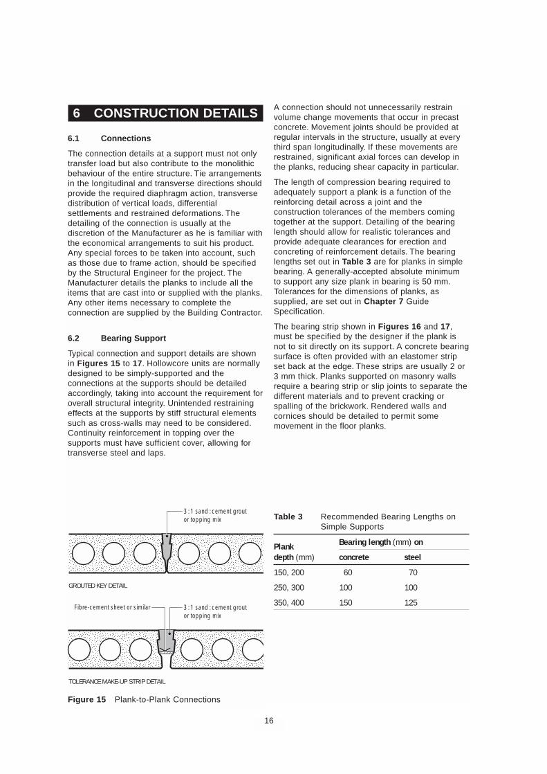
Construction tolerances must be allowed for indeveloping a plan layout. Tolerance in plank lengthis absorbed by allowing a gap at the end of theplank and specifying the minimum length ofbearing. A clearance gap is also required along theside of a plank that abuts a wall or beam to allowfor an accumulation of width tolerances. Smallincreases in floor width can be accommodated byincreasing joint width with the use of a strip offormer to bridge the base of the joint duringgrouting, Figure 15.
Camber and Topping
Hollowcore floor planks are cambered because ofthe upward bending induced by the prestressing,Figure 1. This camber should be allowed for indetailing the planks and the joints at abutting walls,door openings and the like. A site-cast toppingunifies the planks into a monolithic floor, takes outdifferential levels between units and provides alevel working surface. The minimum thickness ofthe topping occurs at the highest point on theplank, usually at the centre. The minimum averagethickness of a structural topping is 50 mm(AS 3600, Cl 8.4.6). For practical purposes, 60 mmtopping is used for up to 200 mm deep planks and80 mm for planks 300-mm and above. Typicalreinforcement is SL62 mesh. Non-structuraltoppings are usually self-levelling mortarsaveraging 10–15 mm in thickness.
It should be clear on the structural drawings wherethe topping thickness is to be measured andwhether it should follow the camber of the plank.The drawings should show the location ofconstruction joints. Where joints are saw-cut thecut should be made within 18 hours of casting thetopping.
4

4 PRELIMINARY DESIGN
1 Determine a feasible arrangement for columns,walls and beams with a minimum number ofdependant load paths. Note the preferredoptions for structural efficiency in Chapter 3.
2 Establish the basic design data:■ Occupancy of the structure■ Fire rating (building regulations)■ Sound transmission class
(building regulations)■ Exposure classifications and durability
requirements (AS 3600).
3 Determine the minimum slab thickness fromfire rating and sound transmission class.Determine the minimum concrete strengthand cover from fire rating, exposureclassification and durability requirements.
4 Select a suitable overall depth of plank andtopping to satisfy deflection control from theguideline values. Typical span to depth ratio forfloors is 30–35, 35–40 for roofs. Floor span todepth ratios in excess of 30 should be checkedfor adequate vibration stiffness. The thickness ofan insitu topping may be determined by thecover to reinforcement at laps.
5 Determine the dead and live loads (AS 1l70).Local loads such as masonry partitions andwheel loads distribute themselves across anumber of planks where possible (Figures 8 to11). Machinery vibrations and such like, mayneed to be considered. Construction loads mustalso be taken into account.
6 Check the strength capacity of the plank fromthe preliminary selection load-span graphs inFigures 2 to 7. The graphs are based on typicalminimum and maximum strand quantities. Foreconomy, a particular plank depth would beused between these lines. A span/loadcombination cannot be to the right of therightmost (maximum) line. Core configurationusually does not affect flexural capacitysignificantly but does affect shear capacity.Always confirm the shear capacity for aparticular configuration.
5
Figure 1 Allowance for Camber
Topping thickness varies with camber
6
0
L/D = 40
0123456789
1011121314
SPAN (m)
LIVE
LOA
D (k
Pa)
1 2 3 4 5 6 7 8 9 10 11 12 0
SPAN (m)
1 2 3 4 5 6 7 8 9 10 11 12
150-mm PLANK WITHOUT TOPPING 150-mm PLANK WITH 60-mm TOPPING
L/D = 40
00123456789
1011121314
SPAN (m)
LIVE
LOA
D (k
Pa)
1 2 3 4 5 6 7 8 9 10 11 12 0
SPAN (m)
1 2 3 4 5 6 7 8 9 10 11 12
200-mm PLANK WITHOUT TOPPING 200-mm PLANK WITH 60-mm TOPPING
L/D = 40 L/D = 40
00123456789
1011121314
SPAN (m)
LIVE
LOA
D (k
Pa)
1 2 3 4 5 6 7 8 10 12 14 169 11 13 15 0
SPAN (m)
1 2 3 4 5 6 7 8 10 12 14 169 11 13 15
250-mm PLANK WITHOUT TOPPING 250-mm PLANK WITH 60-mm TOPPING
L/D = 40 L/D = 40
Figure 2 150-mm Hollowcore Planks – Live Load Capacity
Figure 3 200-mm Hollowcore Planks – Live Load Capacity
Figure 4 250-mm Hollowcore Planks – Live Load Capacity
7
00123456789
1011121314
SPAN (m)
LIVE
LOA
D (k
Pa)
1 2 3 4 5 6 7 8 10 12 14 169 11 13 15 0
SPAN (m)
1 2 3 4 5 6 7 8 10 12 14 169 11 13 15
300-mm PLANK WITHOUT TOPPING 300-mm PLANK WITH 80-mm TOPPING
L/D = 40 L/D = 40
00123456789
1011121314
SPAN (m)
LIVE
LOA
D (k
Pa)
2 4 6 8 10 12 14 16 18 20 0
SPAN (m)
2 4 6 8 10 12 14 16 18 20
350-mm PLANK WITHOUT TOPPING 350-mm PLANK WITH 80-mm TOPPING
L/D = 40 L/D = 40
00123456789
1011121314
SPAN (m)
LIVE
LOA
D (k
Pa)
2 4 6 8 10 12 14 16 18 20 0
SPAN (m)
2 4 6 8 10 12 14 16 18 20
400-mm PLANK WITHOUT TOPPING 400-mm PLANK WITH 80-mm TOPPING
L/D = 40 L/D = 40
Figure 5 300-mm Hollowcore Planks – Live Load Capacity
Figure 6 350-mm Hollowcore Planks – Live Load Capacity
Figure 7 400-mm Hollowcore Planks – Live Load Capacity
5 FINAL DESIGN
5.1 General
The detailed design of a hollowcore plank followsthe normal procedure for a prestressed member(see Sample Calculation Chapter 9). The plank ischecked for design ultimate strength in bending,shear and at transfer, and at service load for crackcontrol, camber at time of erection and deflection.For the standard conditions of uniformly distributedlive load, the manufacturer's load tables take intoaccount these design criteria and show the loadcapacity based on the governing criteria. For non-uniform load cases or non-standard conditionsseparate calculations are required. The designsteps are outlined in the following sections.
5.2 Section Availability
Each hollowcore manufacturer has a standard setof cross-sections that can be produced by theirmachine. Depths vary from 150 to 400 mm. Thecore configuration makes each system unique,actual depths vary between manufacturers and notall are available in each system.
Hollowcore manufacturers prepare and distributeproduct literature that includes section propertiesand capacities and load span tables for theirproduct range. These are calculated for theparticular planks, strand configuration and effectivedepth of the section with concrete cover to meetdesignated fire rating and exposure classifications.
For the purpose of this Manual, typical sectionplank capacity charts are provided as an aid forpreliminary sizing and to illustrate the proceduresfor a detailed final design. In practice, the amountof prestress is varied to suit the load within eachplank size. Top strands are required in 350-mmand 400-mm deep sections (3 x 12.7-mm dia.) tocontrol the stress distribution. Concrete strengthsrange from 40 to 65 MPa and topping strength isusually 32 or 40 MPa.
For convenience, the load-span graphs (Figures 2to 7) are presented in terms of the allowablesuperimposed distributed live load applied to asimply-supported span. Where added dead loadsor concentrated loads are applied to the floor,these can be converted to equivalent uniform liveloads for a preliminary design. Refer Figures 8to 11.
5.3 Flexural Strength
The design ultimate bending strength of the section iscalculated in accordance with Clause 8.1 of AS 3600.The design strength φMu may be calculated using therectangular stress block for compression taking intoaccount any area reduction due to the presence ofcores. The maximum stress in the strands at ultimatemay be determined by either strain compatibility or bythe approximate formula in Clause 8.1.5. of AS 3600.The capacity reduction factor, φ, is 0.8. The strandlength to develop the prestress by bond is 60 stranddiameters. The bond length to develop the stress atultimate flexure is approximately 150 diameters.
To ensure a ductile failure, upper and lower limits areplaced on the area of prestressing steel. A minimumarea of steel has to be provided so that the ultimatecapacity of the section is not less than 1.2 times thecracking moment. This ensures that when the sectioncracks the strand will not simultaneously fail. Themaximum quantity of prestress steel is controlled by therequirement that the neutral axis depth does notexceed 0.4 times the effective depth of the section. Inpractice over-reinforced hollowcore sections areprecluded by the number of strands that can be bondedbetween the cores. The compression zone ofcomposite sections is usually above the core zone ofthe plank.
5.4 Shear Strength
Hollowcore planks are designed for shear inaccordance with Clause 8.2 of AS 3600. Stirrupscannot be provided in hollowcore planks and thecapacity of the section is controlled by concretestrength. The capacity in both flexure-shear crackingand web cracking is calculated and the lesser valuetaken as φVuc where φ = 0.7. Negative moments canreduce the shear capacity by causing prematurecracking in the web. Precautions need to be taken in thedesign to ensure that this does not happen, seeClause 5.9 Continuity.
The shear capacity of given plank sizes varies betweenmanufacturers due to different void configurations.These affect the web width at the neutral axis whereshear stress is a maximum. The load capacity charts inthis Manual assume that shear is not critical for the loadranges shown, this may not be the case for all types ofcross-section, particularly those with large circular voidsand needs to be checked with the individualmanufacturer.
In addition to the check for vertical shear, thelongitudinal shear strength of a composite section mustbe checked at the interface between the plank and theinsitu topping in accordance with Clause 8.4, AS 3600.When the surface texture at the top of the plank isas-screeded by the machine, a shear plane coefficientof 0.2 may be used in the calculation and 0.4 when thesurface is intentionally roughened or wire brushed.
8
5.5 Transfer Stress
When the strands are cut and apply the prestressforce to the concrete, only the self-weight of theplank acts to counter the upward bending momentdue to eccentricity. The strength of the sectionshould be checked for crushing or cracking of theconcrete. Although Clause 8.1.4 of AS 3600specifies a maximum compressive stress in theconcrete at release of 0.5 times the cylinderstrength, a factor of 0.6 has been found to besatisfactory. In practice this limiting stress is met bychoosing the release strength of the concrete. Thetensile stress in the section at release is notcritical for the strand patterns normally used.
5.6 Crack Control
Flexural cracking in a prestressed slab may becontrolled by limiting the tensile stress inaccordance with the provisions of Clause 9.4.2. ofAS 3600. As the strands in hollowcore planks arefully bonded, a calculated flexural tensile stressunder short-term service loads up to 0.5√f’c maybe used in the design. This means that the sectionis effectively uncracked at normal service loads.
Alternatively, the more general provision for partialprestressing may be adopted whereby theincrement in strand stress is limited to 150 MPa asthe load increases from the decompression valueto the short-term service load.
5.7 Camber and Deflection
Camber is the upward deflection of a prestressedmember and results from the prestressing forcebeing eccentric to the centre-of-gravity of thesection. It is therefore determined by the designloading and span for a given depth of plank andshould not be specified as a limiting value.Unloaded planks tend to creep upwards when theself-weight of the plank is insufficient to balancethe prestress. To avoid unnecessarily-highcambers, it is important not to over-specify thedesign loading or arbitrarily increase the prestress.
When the design live load is high, the resultingcamber can be reduced by using additional topstrand to give a less triangular stress distributionover the cross-section.
The initial camber is calculated from the formulaefor elastic deflection due to the prestressingmoment and the self-weight using appropriatevalues for the prestressing force and the modulusof elasticity at release. As these are known withreasonable accuracy the elastic deflection can bepredicted fairly well. However, time-dependentcamber and deflection calculations are onlyestimates.
The camber at erection due to prestress can beestimated using a creep factor of 1.7 to 2.0 timesthe initial camber.
Deflection results from the applied loads. If thesection is uncracked the deflection depends on thestiffness of the gross concrete section and isindependent of the amount of prestressing. Usuallyhollowcore planks are designed to be uncrackedunder service loads so the gross moment of inertiamay be used, otherwise the effective moment ofinertia of the cracked section must be taken intoaccount.
Camber and deflection change with time due toconcrete creep, loss of prestress and other long-term factors such as climate. A long-term load inexcess of the load balanced by the prestresscauses the plank to creep downwards.
Composite action with a topping results in a stiffersection. The deflection of interest is the movementfrom the as-cast level of the topping resulting fromthe long-term effect of the sustained load and theinstantaneous effect of the short-term load.Limiting values for these deflections are specifiedin AS 3600, Table 2.4.2. As an aid to estimatingdeflection, long-term multiplication factors aregiven in reference 4, Chapter 8 and are used inthe Sample Calculation, Chapter 9.
5.8 Load Distribution
Hollowcore floor planks are usually designed assimple, one-way-spanning slabs. Floors are oftensubject to non-uniform loads such as line loads,concentrated loads or loads at openings. Theshear/torsion interaction between planks withproperly-filled side joints and lateral restraintagainst spreading, allows these concentrations tobe shared by several planks.
This ability to distribute loads has beendemonstrated by full scale testing and explainedby a combination of shear stresses induced in thegrouted keyways and by transverse bending in theplanks. For design purposes, an effective load-resisting width can be used to calculate designbending moments and shears. This effective widthdepends upon the span.
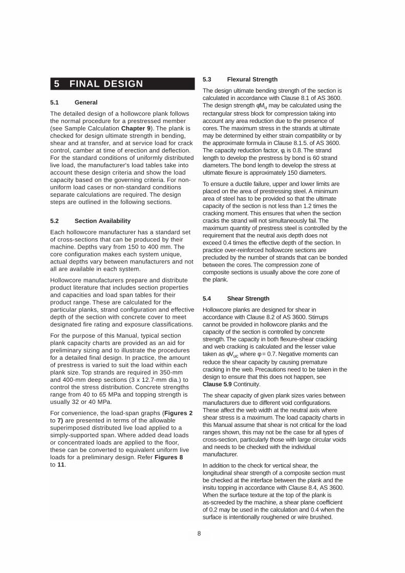
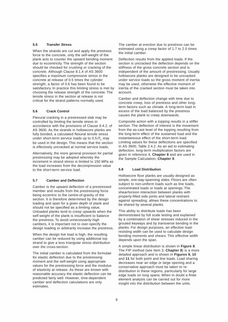
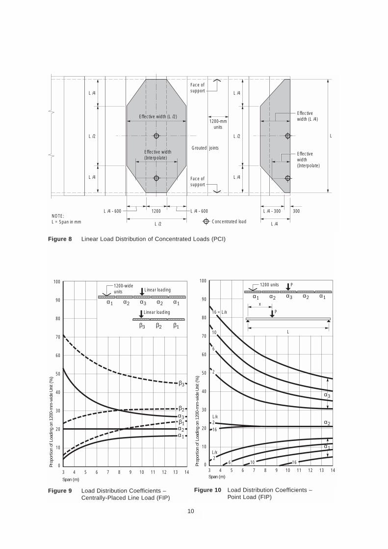
A simple linear distribution is shown in Figure 8.The FIP method (see Item 3, Chapter 8) is a moredetailed approach and is shown in Figures 9, 10and 11 for both point and line loads. Load sharingdecreases near an edge or large opening and aconservative approach must be taken to re-distribution in these regions, particularly for largeedge loads on long spans. When in doubt a finiteelement analysis can be carried out for moreinsight into the distribution between the units.
9
10
Figure 8 Linear Load Distribution of Concentrated Loads (PCI)
Face ofsupport
Grouted joints
Face ofsupport
L
L /4
L /4
L /2
L /4
L /4
L /4 - 600 L /4 - 600
L /2
L /2
1200
Concentrated loadNOTE:L = Span in mm
L /4 - 300
L /4
Effectivewidth(Interpolate)
300
1200-mmunits
Effectivewidth (L /4)
Effective width(Interpolate)
Effective width (L /2)
Figure 9 Load Distribution Coefficients –Centrally-Placed Line Load (FIP)
Figure 10 Load Distribution Coefficients –Point Load (FIP)
Linear loading
α1
α1
α2
α3
α2 α3 α2 α1
Linear loading
β3 β2 β1
β3
β2
β1
100
90
80
70
60
50
40
30
20
10
03 1413121110987654Span (m)
Prop
ortio
n of
Loa
ding
on
1200
-mm
-wid
e Un
it (%
)
1200-wideunits
P
P16 = L/x
10
16
6
2
L/x2
L/x 2
6 10 16
L
x
α1
α2
α2 α3 α2 α1
100
90
80
70
60
50
40
30
20
10
03 1413121110987654Span (m)
Prop
ortio
n of
Loa
ding
on
1200
-mm
-wid
e Un
it (%
)
1200 units
α3
α1
5.9 Continuity
The most economical use of planks in a framedstructure is as simply-supported members in alayout which has a larger plank span than supportbeam span. Sufficient tie steel (which will give adegree of continuity) as described below must besupplied whether the planks are topped or not.
Care must be taken not to develop unintentionalnegative moments at the support of untoppedplanks. There may already be tension here due toprestress eccentricity and additional tension couldinitiate web cracking. Neglect of correct detailingcould lead to shear failure at unexpectedly-lowloading. Two typical causes of negative momentsare:
■ Grout from the butt-end joint penetrating into thecores and creating a stiff end-length. Core damsshould always be located within 50 mm of theend of the plank.
■ The ends of the planks clamped betweenbearing walls, restraining rotation. A clearanceor compressible material can be used to preventthe upper wall bearing on the plank.
Limited continuity can be achieved by placingreinforcement in the topping concrete at supports.Continuity should only used where there is a clearadvantage to the structure to do so, and then, only incomposite construction. The cost per kN of forcesupplied by prestressing strand is about a third thatof reinforcement. Thus, it is uneconomical to useordinary reinforcement as negative-moment steel toreplace positive-moment strand steel.
Continuity can be used to achieve a higher fire-ratingfor a given cover to the strand; this is useful when itis not possible, or inadvisable, to raise the strandany higher in the cross-section. Continuity is alsouseful for increasing the robustness of a structure tocatastrophic overload. The following points should beobserved:
■ Do not interchange the sections of differentmanufacturers without re-calculating the shearcapacity. Web widths between different coreprofiles can vary by up to 60% with a similareffect on the shear capacity.
■ Core filling may be required to make up shearcapacity. Check flexural tension.
■ Check that the strand eccentricity does notexceed the cracking moment in the top surface atthe end of the plank. If necessary, provide topstrand in the plank (two or three is usuallysufficient).
■ Extend negative reinforcement in the topping wellpast the expected point of contraflexure to ensurethat uncontrolled cracking cannot penetrate intothe precast unit.
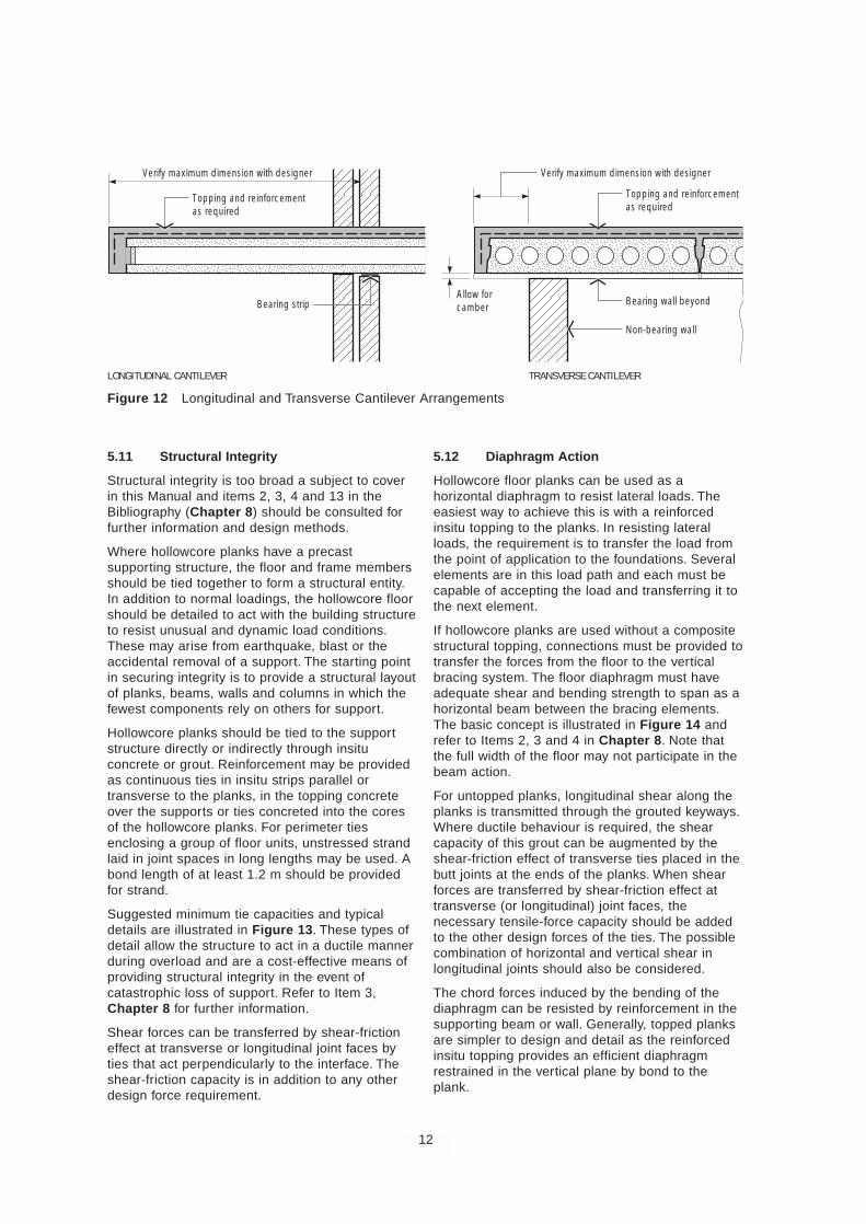
5.10 Cantilevers
Cantilevers are a special case of continuity over asupport. Frequently untopped planks are used in thisway, Figure 12. For the cantilever portion of theplank, the bottom strands add to the bendingmoment at the support. Depending on the system ofmanufacture, it may be possible to de-bond some ofthese strands over the length of the cantilever. Tocontrol deflection, the length of a cantilever is limitedto 8 to 10 times the plank thickness.
Where a composite topping is used, normalreinforcing bar or fabric is provided in the toppinglayer for the negative moment.
If the floor is untopped then sufficient top strands arerequired in the plank to meet ultimate shear andflexure requirements and ensure that the top surfaceis in residual compression under service loads.However, for short cantilevers (say up to 750-mm)bars may be grouted in the cores or joints betweenplanks. Both the construction loads and final serviceloads must be considered. Some temporary proppingmay be required during construction.
11
Figure 11 Load Distribution Coefficients –Point Load at Edge (FIP)
P
P
L
x = 0.5 Lα1
α1α2α3α4α5
α2 α3 α4 α5
100
90
80
70
60
50
40
30
20
10
03 1413121110987654Span (m)
Prop
ortio
n of
Loa
ding
on
1200
-mm
-wid
e Un
it (%
)
1200-mm-wide units
5.11 Structural Integrity
Structural integrity is too broad a subject to coverin this Manual and items 2, 3, 4 and 13 in theBibliography (Chapter 8) should be consulted forfurther information and design methods.
Where hollowcore planks have a precastsupporting structure, the floor and frame membersshould be tied together to form a structural entity.In addition to normal loadings, the hollowcore floorshould be detailed to act with the building structureto resist unusual and dynamic load conditions.These may arise from earthquake, blast or theaccidental removal of a support. The starting pointin securing integrity is to provide a structural layoutof planks, beams, walls and columns in which thefewest components rely on others for support.
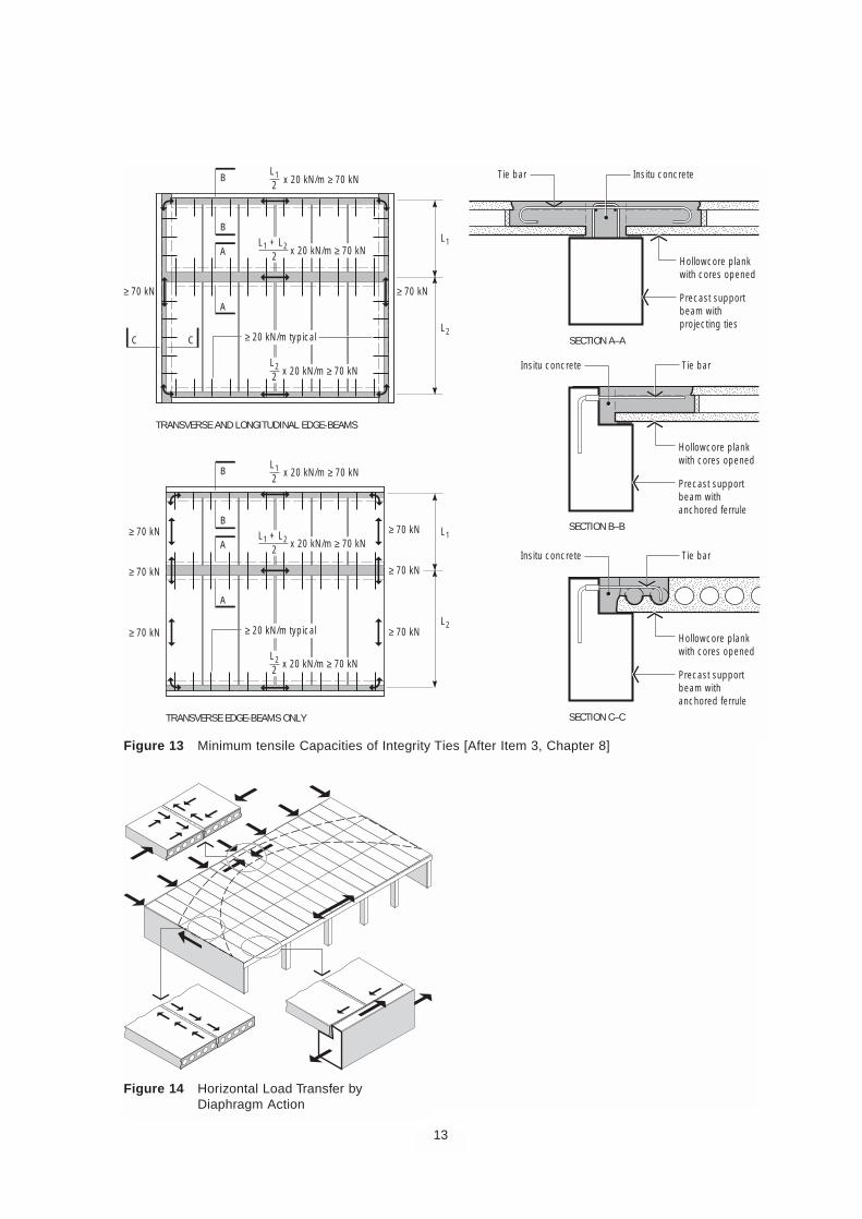
Hollowcore planks should be tied to the supportstructure directly or indirectly through insituconcrete or grout. Reinforcement may be providedas continuous ties in insitu strips parallel ortransverse to the planks, in the topping concreteover the supports or ties concreted into the coresof the hollowcore planks. For perimeter tiesenclosing a group of floor units, unstressed strandlaid in joint spaces in long lengths may be used. Abond length of at least 1.2 m should be providedfor strand.
Suggested minimum tie capacities and typicaldetails are illustrated in Figure 13. These types ofdetail allow the structure to act in a ductile mannerduring overload and are a cost-effective means ofproviding structural integrity in the event ofcatastrophic loss of support. Refer to Item 3,Chapter 8 for further information.
Shear forces can be transferred by shear-frictioneffect at transverse or longitudinal joint faces byties that act perpendicularly to the interface. Theshear-friction capacity is in addition to any otherdesign force requirement.
5.12 Diaphragm Action
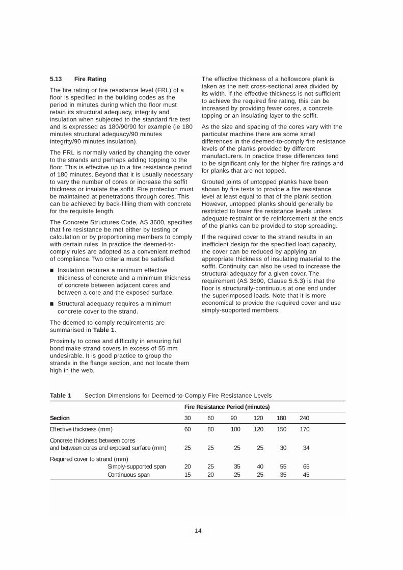
Hollowcore floor planks can be used as ahorizontal diaphragm to resist lateral loads. Theeasiest way to achieve this is with a reinforcedinsitu topping to the planks. In resisting lateralloads, the requirement is to transfer the load fromthe point of application to the foundations. Severalelements are in this load path and each must becapable of accepting the load and transferring it tothe next element.
If hollowcore planks are used without a compositestructural topping, connections must be provided totransfer the forces from the floor to the verticalbracing system. The floor diaphragm must haveadequate shear and bending strength to span as ahorizontal beam between the bracing elements.The basic concept is illustrated in Figure 14 andrefer to Items 2, 3 and 4 in Chapter 8. Note thatthe full width of the floor may not participate in thebeam action.
For untopped planks, longitudinal shear along theplanks is transmitted through the grouted keyways.Where ductile behaviour is required, the shearcapacity of this grout can be augmented by theshear-friction effect of transverse ties placed in thebutt joints at the ends of the planks. When shearforces are transferred by shear-friction effect attransverse (or longitudinal) joint faces, thenecessary tensile-force capacity should be addedto the other design forces of the ties. The possiblecombination of horizontal and vertical shear inlongitudinal joints should also be considered.
The chord forces induced by the bending of thediaphragm can be resisted by reinforcement in thesupporting beam or wall. Generally, topped planksare simpler to design and detail as the reinforcedinsitu topping provides an efficient diaphragmrestrained in the vertical plane by bond to theplank.
12
Figure 12 Longitudinal and Transverse Cantilever Arrangements
Allow forcamberBearing strip Bearing wall beyond
Topping and reinforcementas required
Non-bearing wall
TRANSVERSE CANTILEVERLONGITUDINAL CANTILEVER
Verify maximum dimension with designer
Topping and reinforcementas required
Verify maximum dimension with designer
13
TRANSVERSE EDGE-BEAMS ONLY
TRANSVERSE AND LONGITUDINAL EDGE-BEAMS
SECTION A–A
SECTION B–B
SECTION C–C
≥ 70 kNPrecast supportbeam withprojecting ties
Hollowcore plankwith cores opened
Tie bar Insitu concrete
≥ 20 kN/m typical
x 20 kN/m ≥ 70 kN
≥ 70 kN
C C
A
A
B
B
Precast supportbeam withanchored ferrule
Hollowcore plankwith cores opened
Tie barInsitu concrete
Tie barInsitu concrete
Precast supportbeam withanchored ferrule
Hollowcore plankwith cores opened
L1
L12
L2
x 20 kN/m ≥ 70 kNL22
x 20 kN/m ≥ 70 kN
x 20 kN/m ≥ 70 kN
L1 + L22
≥ 70 kN
≥ 70 kN
≥ 70 kN≥ 20 kN/m typical
≥ 70 kN
≥ 70 kN
≥ 70 kN
A
A
B
B
L1
L12
L2
L22
L1 + L22
x 20 kN/m ≥ 70 kN
x 20 kN/m ≥ 70 kN
Figure 13 Minimum tensile Capacities of Integrity Ties [After Item 3, Chapter 8]
Figure 14 Horizontal Load Transfer byDiaphragm Action
5.13 Fire Rating
The fire rating or fire resistance level (FRL) of afloor is specified in the building codes as theperiod in minutes during which the floor mustretain its structural adequacy, integrity andinsulation when subjected to the standard fire testand is expressed as 180/90/90 for example (ie 180minutes structural adequacy/90 minutesintegrity/90 minutes insulation).
The FRL is normally varied by changing the coverto the strands and perhaps adding topping to thefloor. This is effective up to a fire resistance periodof 180 minutes. Beyond that it is usually necessaryto vary the number of cores or increase the soffitthickness or insulate the soffit. Fire protection mustbe maintained at penetrations through cores. Thiscan be achieved by back-filling them with concretefor the requisite length.
The Concrete Structures Code, AS 3600, specifiesthat fire resistance be met either by testing orcalculation or by proportioning members to complywith certain rules. In practice the deemed-to-comply rules are adopted as a convenient methodof compliance. Two criteria must be satisfied.
■ Insulation requires a minimum effectivethickness of concrete and a minimum thicknessof concrete between adjacent cores andbetween a core and the exposed surface.
■ Structural adequacy requires a minimumconcrete cover to the strand.
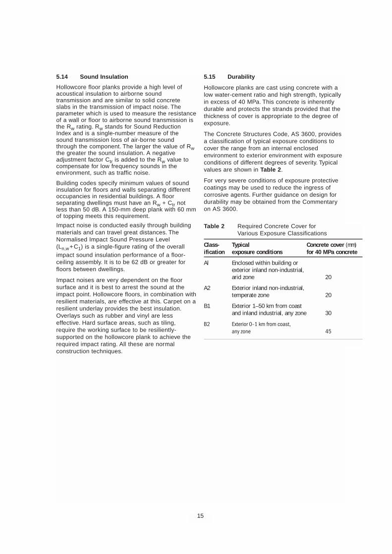
The deemed-to-comply requirements aresummarised in Table 1.
Proximity to cores and difficulty in ensuring fullbond make strand covers in excess of 55 mmundesirable. It is good practice to group thestrands in the flange section, and not locate themhigh in the web.
The effective thickness of a hollowcore plank istaken as the nett cross-sectional area divided byits width. If the effective thickness is not sufficientto achieve the required fire rating, this can beincreased by providing fewer cores, a concretetopping or an insulating layer to the soffit.
As the size and spacing of the cores vary with theparticular machine there are some smalldifferences in the deemed-to-comply fire resistancelevels of the planks provided by differentmanufacturers. In practice these differences tendto be significant only for the higher fire ratings andfor planks that are not topped.
Grouted joints of untopped planks have beenshown by fire tests to provide a fire resistancelevel at least equal to that of the plank section.However, untopped planks should generally berestricted to lower fire resistance levels unlessadequate restraint or tie reinforcement at the endsof the planks can be provided to stop spreading.
If the required cover to the strand results in aninefficient design for the specified load capacity,the cover can be reduced by applying anappropriate thickness of insulating material to thesoffit. Continuity can also be used to increase thestructural adequacy for a given cover. Therequirement (AS 3600, Clause 5.5.3) is that thefloor is structurally-continuous at one end underthe superimposed loads. Note that it is moreeconomical to provide the required cover and usesimply-supported members.
14
Table 1 Section Dimensions for Deemed-to-Comply Fire Resistance Levels
Fire Resistance Period (minutes)
Section 30 60 90 120 180 240
Effective thickness (mm) 60 80 100 120 150 170
Concrete thickness between coresand between cores and exposed surface (mm) 25 25 25 25 30 34
Required cover to strand (mm)Simply-supported span 20 25 35 40 55 65Continuous span 15 20 25 25 35 45
5.14 Sound Insulation
Hollowcore floor planks provide a high level ofacoustical insulation to airborne soundtransmission and are similar to solid concreteslabs in the transmission of impact noise. Theparameter which is used to measure the resistanceof a wall or floor to airborne sound transmission isthe Rw rating. Rw stands for Sound ReductionIndex and is a single-number measure of thesound transmission loss of air-borne soundthrough the component. The larger the value of Rwthe greater the sound insulation. A negativeadjustment factor Ctr is added to the Rw value tocompensate for low frequency sounds in theenvironment, such as traffic noise.
Building codes specify minimum values of soundinsulation for floors and walls separating differentoccupancies in residential buildings. A floorseparating dwellings must have an Rw + Ctr notless than 50 dB. A 150-mm deep plank with 60 mmof topping meets this requirement.
Impact noise is conducted easily through buildingmaterials and can travel great distances. TheNormalised Impact Sound Pressure Level(Ln,w+C1) is a single-figure rating of the overallimpact sound insulation performance of a floor-ceiling assembly. It is to be 62 dB or greater forfloors between dwellings.
Impact noises are very dependent on the floorsurface and it is best to arrest the sound at theimpact point. Hollowcore floors, in combination withresilient materials, are effective at this. Carpet on aresilient underlay provides the best insulation.Overlays such as rubber and vinyl are lesseffective. Hard surface areas, such as tiling,require the working surface to be resiliently-supported on the hollowcore plank to achieve therequired impact rating. All these are normalconstruction techniques.
5.15 Durability
Hollowcore planks are cast using concrete with alow water-cement ratio and high strength, typicallyin excess of 40 MPa. This concrete is inherentlydurable and protects the strands provided that thethickness of cover is appropriate to the degree ofexposure.
The Concrete Structures Code, AS 3600, providesa classification of typical exposure conditions tocover the range from an internal enclosedenvironment to exterior environment with exposureconditions of different degrees of severity. Typicalvalues are shown in Table 2.
For very severe conditions of exposure protectivecoatings may be used to reduce the ingress ofcorrosive agents. Further guidance on design fordurability may be obtained from the Commentaryon AS 3600.
15
Table 2 Required Concrete Cover forVarious Exposure Classifications
Class- Typical Concrete cover (mm)ification exposure conditions for 40 MPa concrete
Al Enclosed within building orexterior inland non-industrial,arid zone 20
A2 Exterior inland non-industrial,temperate zone 20
B1 Exterior 1–50 km from coastand inland industrial, any zone 30
B2 Exterior 0–1 km from coast,any zone 45
6 CONSTRUCTION DETAILS
6.1 Connections
The connection details at a support must not onlytransfer load but also contribute to the monolithicbehaviour of the entire structure. Tie arrangementsin the longitudinal and transverse directions shouldprovide the required diaphragm action, transversedistribution of vertical loads, differentialsettlements and restrained deformations. Thedetailing of the connection is usually at thediscretion of the Manufacturer as he is familiar withthe economical arrangements to suit his product.Any special forces to be taken into account, suchas those due to frame action, should be specifiedby the Structural Engineer for the project. TheManufacturer details the planks to include all theitems that are cast into or supplied with the planks.Any other items necessary to complete theconnection are supplied by the Building Contractor.
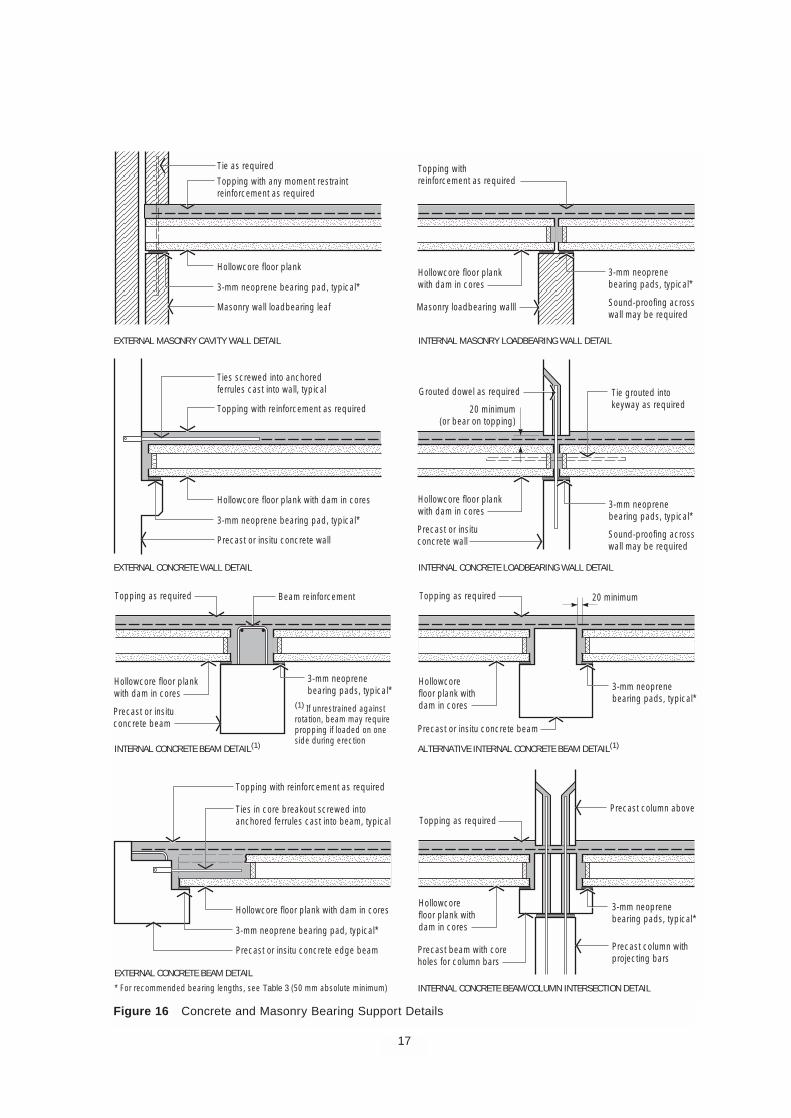
6.2 Bearing Support
Typical connection and support details are shownin Figures 15 to 17. Hollowcore units are normallydesigned to be simply-supported and theconnections at the supports should be detailedaccordingly, taking into account the requirement foroverall structural integrity. Unintended restrainingeffects at the supports by stiff structural elementssuch as cross-walls may need to be considered.Continuity reinforcement in topping over thesupports must have sufficient cover, allowing fortransverse steel and laps.
A connection should not unnecessarily restrainvolume change movements that occur in precastconcrete. Movement joints should be provided atregular intervals in the structure, usually at everythird span longitudinally. If these movements arerestrained, significant axial forces can develop inthe planks, reducing shear capacity in particular.
The length of compression bearing required toadequately support a plank is a function of thereinforcing detail across a joint and theconstruction tolerances of the members comingtogether at the support. Detailing of the bearinglength should allow for realistic tolerances andprovide adequate clearances for erection andconcreting of reinforcement details. The bearinglengths set out in Table 3 are for planks in simplebearing. A generally-accepted absolute minimumto support any size plank in bearing is 50 mm.Tolerances for the dimensions of planks, assupplied, are set out in Chapter 7 GuideSpecification.
The bearing strip shown in Figures 16 and 17,must be specified by the designer if the plank isnot to sit directly on its support. A concrete bearingsurface is often provided with an elastomer stripset back at the edge. These strips are usually 2 or3 mm thick. Planks supported on masonry wallsrequire a bearing strip or slip joints to separate thedifferent materials and to prevent cracking orspalling of the brickwork. Rendered walls andcornices should be detailed to permit somemovement in the floor planks.
16
Table 3 Recommended Bearing Lengths onSimple Supports
Plank Bearing length (mm) on
depth (mm) concrete steel
150, 200 60 70
250, 300 100 100
350, 400 150 125Fibre-cement sheet or similar
3 : 1 sand : cement groutor topping mix
GROUTED KEY DETAIL
TOLERANCE MAKE-UP STRIP DETAIL
3 : 1 sand : cement groutor topping mix
Figure 15 Plank-to-Plank Connections
17
Figure 16 Concrete and Masonry Bearing Support Details
Masonry wall loadbearing leaf
3-mm neoprene bearing pad, typical*
EXTERNAL MASONRY CAVITY WALL DETAIL INTERNAL MASONRY LOADBEARING WALL DETAIL
EXTERNAL CONCRETE WALL DETAIL INTERNAL CONCRETE LOADBEARING WALL DETAIL
INTERNAL CONCRETE BEAM DETAIL(1)
EXTERNAL CONCRETE BEAM DETAIL
ALTERNATIVE INTERNAL CONCRETE BEAM DETAIL(1)
INTERNAL CONCRETE BEAM/COLUMN INTERSECTION DETAIL
Hollowcore floor plank
Tie as required
Topping with any moment restraintreinforcement as required
Precast or insitu concrete wall
3-mm neoprene bearing pad, typical*
Precast column withprojecting bars
Precast column above
Hollowcore floor plank with dam in cores
Topping with reinforcement as required
Topping as required
Precast or insituconcrete wall
3-mm neoprenebearing pads, typical*
Tie grouted intokeyway as required
Grouted dowel as required
20 minimum(or bear on topping)
Beam reinforcement
Ties screwed into anchoredferrules cast into wall, typical
Precast or insitu concrete edge beam
* For recommended bearing lengths, see Table 3 (50 mm absolute minimum)
3-mm neoprene bearing pad, typical*
Hollowcore floor plank with dam in cores
Topping with reinforcement as required
Ties in core breakout screwed intoanchored ferrules cast into beam, typical
Masonry loadbearing walll
3-mm neoprenebearing pads, typical*
Sound-proofing acrosswall may be required
Sound-proofing acrosswall may be required
Hollowcore floor plankwith dam in cores
Topping withreinforcement as required
Hollowcore floor plankwith dam in cores
Precast or insituconcrete beam
3-mm neoprenebearing pads, typical*
(1) If unrestrained againstrotation, beam may requirepropping if loaded on oneside during erection
Hollowcore floor plankwith dam in cores
Topping as required 20 minimum
Precast or insitu concrete beam
3-mm neoprenebearing pads, typical*
3-mm neoprenebearing pads, typical*
Hollowcorefloor plank withdam in cores
Topping as required
Precast beam with coreholes for column bars
Hollowcorefloor plank withdam in cores
18
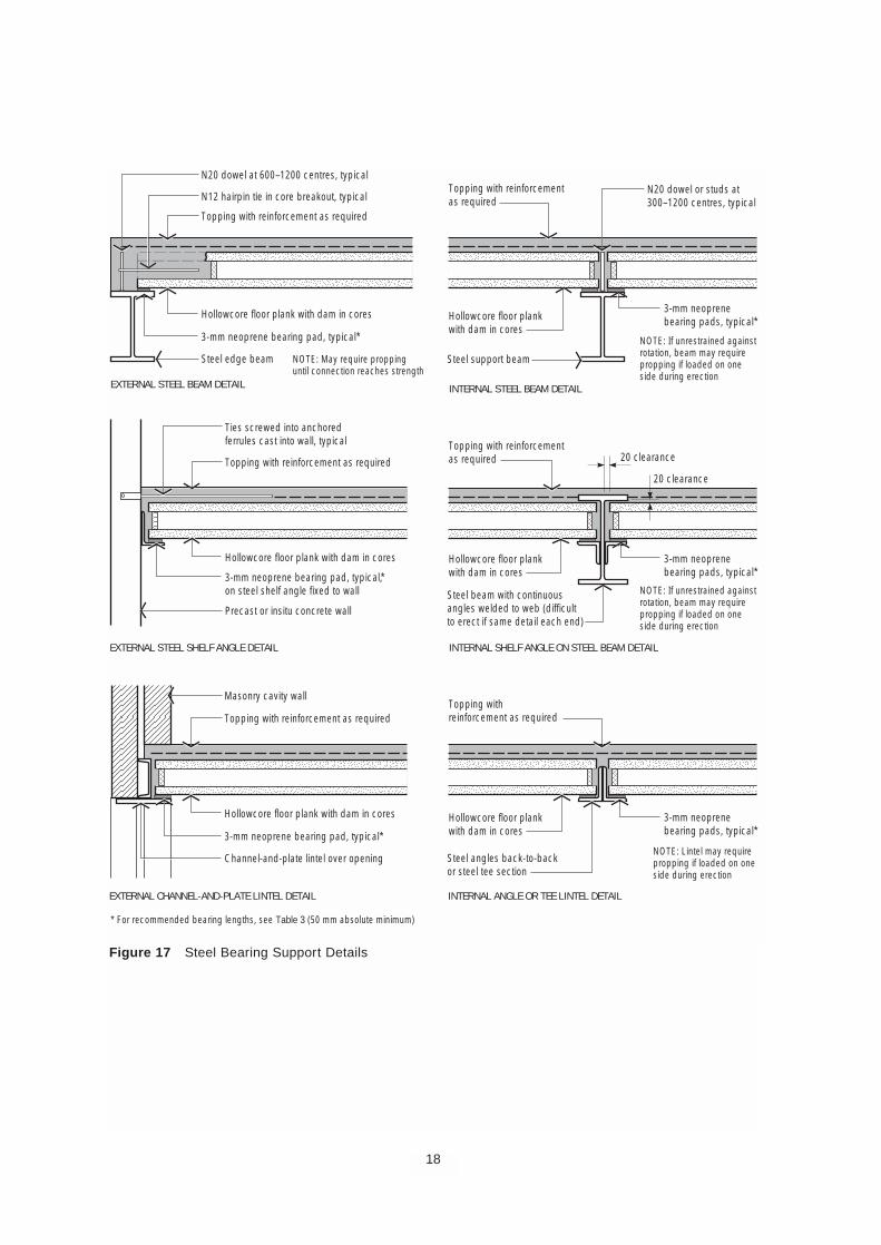
Figure 17 Steel Bearing Support Details
Channel-and-plate lintel over opening
3-mm neoprene bearing pad, typical*
EXTERNAL CHANNEL-AND-PLATE LINTEL DETAIL INTERNAL ANGLE OR TEE LINTEL DETAIL
INTERNAL STEEL BEAM DETAIL
EXTERNAL STEEL SHELF ANGLE DETAIL INTERNAL SHELF ANGLE ON STEEL BEAM DETAIL
EXTERNAL STEEL BEAM DETAIL
Hollowcore floor plank with dam in cores
Masonry cavity wall
Topping with reinforcement as required
Precast or insitu concrete wall
3-mm neoprene bearing pad, typical,*on steel shelf angle fixed to wall
Hollowcore floor plank with dam in cores
Topping with reinforcement as required
Ties screwed into anchoredferrules cast into wall, typical
Steel edge beam NOTE: May require proppinguntil connection reaches strength
NOTE: If unrestrained againstrotation, beam may requirepropping if loaded on oneside during erection
NOTE: If unrestrained againstrotation, beam may requirepropping if loaded on oneside during erection
NOTE: Lintel may requirepropping if loaded on oneside during erection
* For recommended bearing lengths, see Table 3 (50 mm absolute minimum)
3-mm neoprene bearing pad, typical*
Hollowcore floor plank with dam in cores
N20 dowel at 600–1200 centres, typical
N12 hairpin tie in core breakout, typical
Topping with reinforcement as required
N20 dowel or studs at300–1200 centres, typical
Steel support beam
3-mm neoprenebearing pads, typical*Hollowcore floor plank
with dam in cores
Topping with reinforcementas required
Steel beam with continuousangles welded to web (difficultto erect if same detail each end)
3-mm neoprenebearing pads, typical*
20 clearance
20 clearance
Hollowcore floor plankwith dam in cores
Topping with reinforcementas required
Steel angles back-to-backor steel tee section
3-mm neoprenebearing pads, typical*
Hollowcore floor plankwith dam in cores
Topping withreinforcement as required
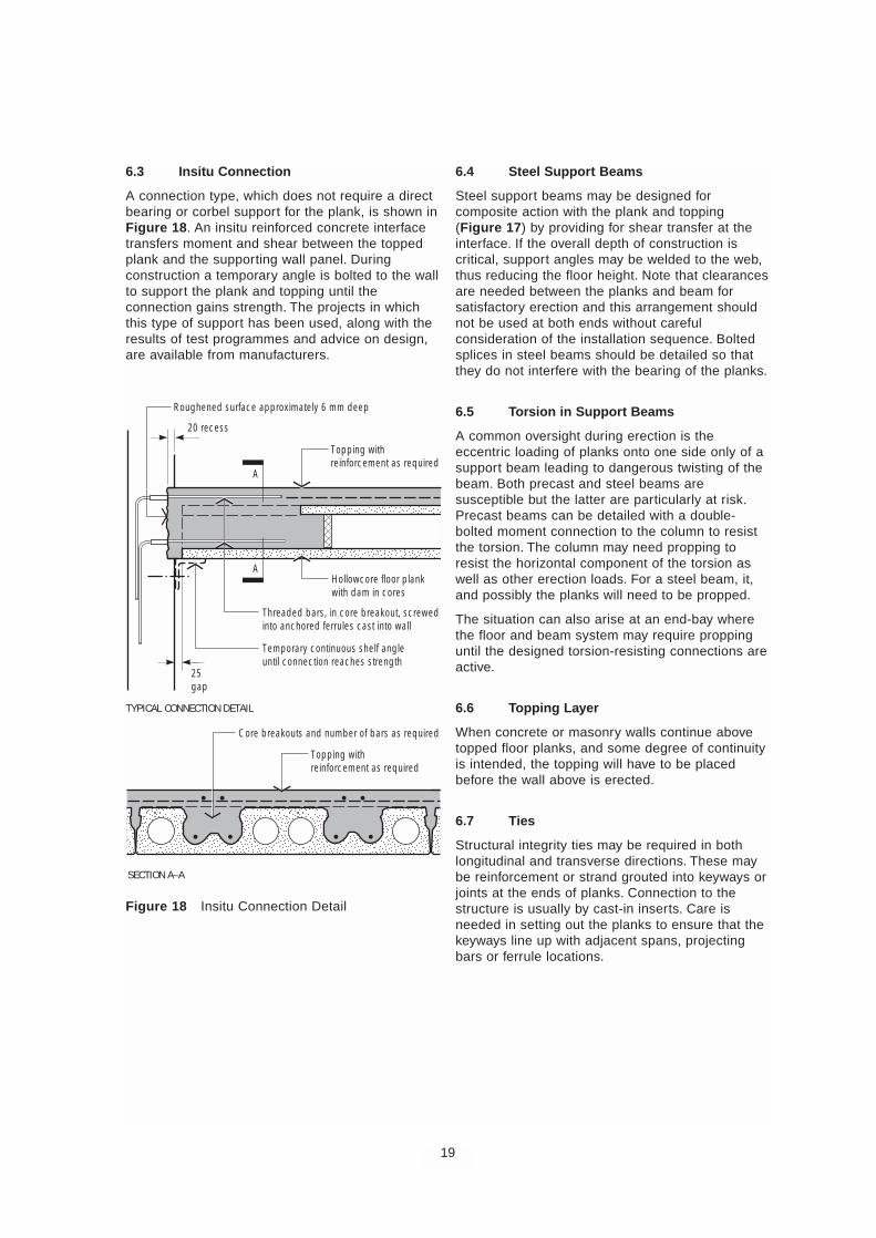
6.3 Insitu Connection
A connection type, which does not require a directbearing or corbel support for the plank, is shown inFigure 18. An insitu reinforced concrete interfacetransfers moment and shear between the toppedplank and the supporting wall panel. Duringconstruction a temporary angle is bolted to the wallto support the plank and topping until theconnection gains strength. The projects in whichthis type of support has been used, along with theresults of test programmes and advice on design,are available from manufacturers.
6.4 Steel Support Beams
Steel support beams may be designed forcomposite action with the plank and topping(Figure 17) by providing for shear transfer at theinterface. If the overall depth of construction iscritical, support angles may be welded to the web,thus reducing the floor height. Note that clearancesare needed between the planks and beam forsatisfactory erection and this arrangement shouldnot be used at both ends without carefulconsideration of the installation sequence. Boltedsplices in steel beams should be detailed so thatthey do not interfere with the bearing of the planks.
6.5 Torsion in Support Beams
A common oversight during erection is theeccentric loading of planks onto one side only of asupport beam leading to dangerous twisting of thebeam. Both precast and steel beams aresusceptible but the latter are particularly at risk.Precast beams can be detailed with a double-bolted moment connection to the column to resistthe torsion. The column may need propping toresist the horizontal component of the torsion aswell as other erection loads. For a steel beam, it,and possibly the planks will need to be propped.
The situation can also arise at an end-bay wherethe floor and beam system may require proppinguntil the designed torsion-resisting connections areactive.
6.6 Topping Layer
When concrete or masonry walls continue abovetopped floor planks, and some degree of continuityis intended, the topping will have to be placedbefore the wall above is erected.
6.7 Ties
Structural integrity ties may be required in bothlongitudinal and transverse directions. These maybe reinforcement or strand grouted into keyways orjoints at the ends of planks. Connection to thestructure is usually by cast-in inserts. Care isneeded in setting out the planks to ensure that thekeyways line up with adjacent spans, projectingbars or ferrule locations.
19
A
25gap
20 recess
A
TYPICAL CONNECTION DETAIL
SECTION A–A
Roughened surface approximately 6 mm deep
Hollowcore floor plankwith dam in cores
Topping withreinforcement as required
Topping withreinforcement as required
Core breakouts and number of bars as required
Temporary continuous shelf angleuntil connection reaches strength
Threaded bars, in core breakout, screwedinto anchored ferrules cast into wall
Figure 18 Insitu Connection Detail
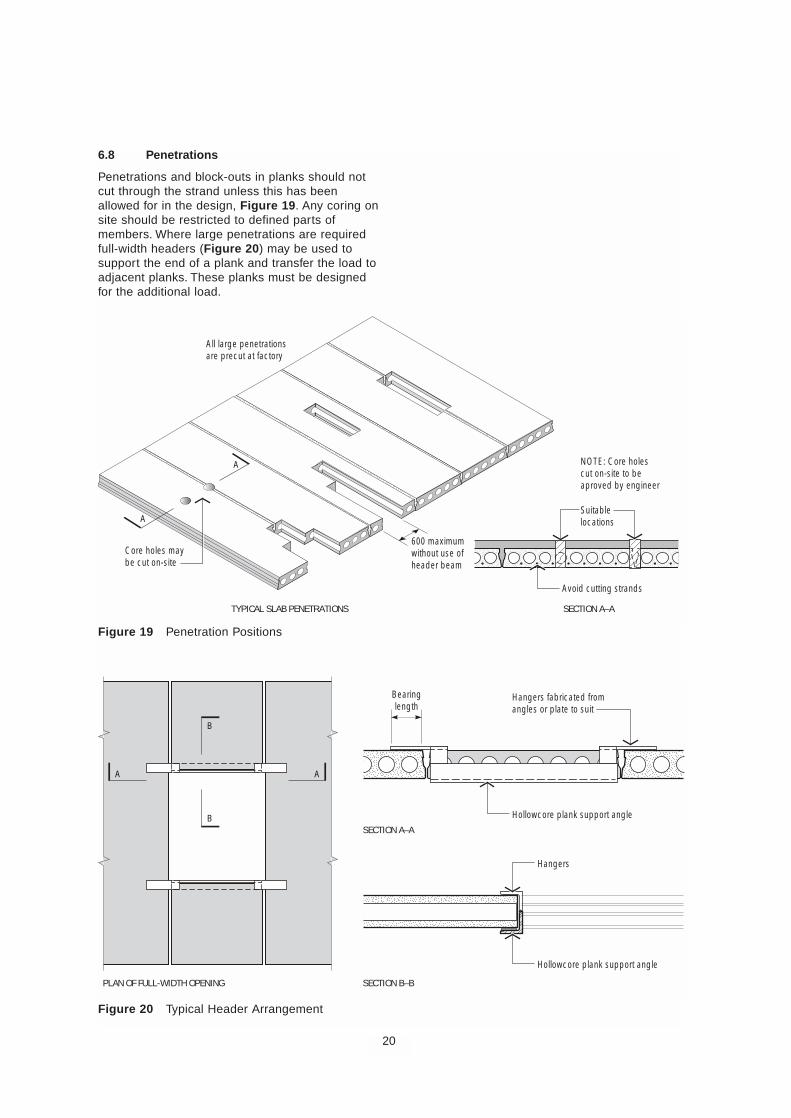
6.8 Penetrations
Penetrations and block-outs in planks should notcut through the strand unless this has beenallowed for in the design, Figure 19. Any coring onsite should be restricted to defined parts ofmembers. Where large penetrations are requiredfull-width headers (Figure 20) may be used tosupport the end of a plank and transfer the load toadjacent planks. These planks must be designedfor the additional load.
20
600 maximumwithout use ofheader beam
Avoid cutting strands
Suitablelocations
NOTE: Core holescut on-site to beaproved by engineer
Core holes maybe cut on-site
All large penetrationsare precut at factory
TYPICAL SLAB PENETRATIONS SECTION A–A
A
A
Figure 19 Penetration Positions
Bearinglength
Hollowcore plank support angle
Hangers fabricated fromangles or plate to suit
Hangers
PLAN OF FULL-WIDTH OPENING SECTION B–B
SECTION A–A
A A
B
B
Hollowcore plank support angle
Figure 20 Typical Header Arrangement
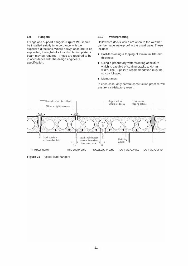
6.9 Hangers
Fixings and support hangers (Figure 21) shouldbe installed strictly in accordance with thesupplier’s directions. Where heavy loads are to besupported, through-bolts to a distribution plate orbeam may be required. These are required to bein accordance with the design engineer’sspecification.
6.10 Waterproofing
Hollowcore decks which are open to the weathercan be made waterproof in the usual ways. Theseinclude:
■ Post-tensioning a topping of minimum 100-mmthickness
■ Using a proprietary waterproofing admixturewhich is capable of sealing cracks to 0.4-mmwidth. The Supplier’s recommendation must bestrictly followed
■ Membranes.
In each case, only careful construction practice willensure a satisfactory result.
21
Figure 21 Typical load hangers
Knock out nib toaccommodate bolt Shot fixing
suitable
100 sq x 10 plate washers
50
Restrict hole locationto these dimensions
from core centre30
THRU-BOLT IN JOINT THRU-BOLT IN CORE TOGGLE BOLT IN CORE LIGHT METAL ANGLE LIGHT METAL STRAP
Thru-bolts of size to suit load Toggle bolt forvertical loads only
Keys grouted,topping optional
7 GUIDE SPECIFICATION
This guide specification is intended to be used inthe preparation of the specification for a particularproject. It should be checked for compatibility withthe particular job requirements by deleting anyprovisions that do not apply and adding specialprovisions needed.
Scope
This guide specification covers the manufactureand erection of hollowcore floor planks producedby an approved manufacturer.
Design
Planks shall be designed in accordance withAS 3600, except where industry practice providesa proven alternative method.
The manufacturer shall prepare and submit shopdrawings for approval of the general arrangementof the planks, adequacy and dimensions prior tomanufacture. Shop drawings shall show thelocation of all planks with all major openingsdetailed. Shop drawings detailing each unit, cast-ininserts and its strand configuration shall besubmitted to the building contractor for approval.
The design of the structure, including checking theadequacy of the hollowcore planks for theirintended use in the structure, shall be theresponsibility of the Structural Engineer for theproject.
Materials
Cement shall comply with AS 3972 andsupplementary cementitious materials withAS 3582 parts 1 and 2. Aggregates shall complywith AS 2758.1. Chemical admixtures shall complywith AS 1478.1.
Prestressing steel shall be stress-relieved low-relaxation strand complying with AS 1311. Strandshall be clean and free of deleterious substancesat the time of concreting.
Concrete shall have a minimum characteristic28-day strength of 40 MPa and shall conform tothe requirements of AS 3600. Concrete strength atrelease of prestress shall be a minimum of 25 MPaor as required by the structural drawings.
Topping concrete shall have a minimumcharacteristic 28-day strength of 32 MPa or asshown on the drawings. If topping concrete is usedto grout the keyways, the maximum aggregate sizeshall be 14 mm.
22
Manufacture
Hollowcore floor planks shall be cast on a long-linebed by an approved machine and mechanicallycompacted. The top surface shall be finished ascast by the machine or intentionally-roughened toachieve the specified bond characteristics of thetopping or other finish applied after erection.
The underside finish shall be as cast against thebed in accordance with good industry practice.Some surface voids and colour variations shall beacceptable in accordance with the sample agreedprior to casting.
Tolerances
Floor planks shall be supplied in accordance withthe following tolerances.
Length + 10 mm - 10 mm
Width + 3 mm - 6 mm
Thickness + 3 mm - 3 mm
Squareness of end + 6 mm - 6 mm
Wind 10 mm per 3000 mm
Location of ferrules + 20 mm - 20 mm
Location of strand + 3 mm - 3 mm
Differential camberadjacent units 2 mm/m span but not
greater than 15 mm
Delivery and Handling
Hollowcore floor planks shall be lifted andsupported during manufacture, storage, transportand erection operations at the nominated liftingpositions only.
Erection
The Building Contractor shall be responsible forproviding true and level bearing surfaces for thesupport of the hollowcore planks. Temporaryshoring and bracing shall also be provided asnecessary to ensure the stability of the structureduring erection. The hollowcore planks shall beinstalled by a competent erection contractor.Where the manufacturer also erects the planks,the Building Contractor shall be responsible forproviding suitable access at the site to enabletrucks and cranes to operate under their ownpower.
Bearing strips shall be accurately set whererequired. Place any reinforcement required by thedrawings. Keyways shall be filled and compactedwith a 3:1 sand-cement grout mix or by the toppingconcrete using a maximum aggregate size of14 mm. Voids at plank ends shall be sealed toprevent penetration of topping into the cores bymore than 50 mm. It should not be more than thesupport length without considering the implicationson the shear capacity.
Attachments and Penetrations
Attachments and fixings to the hollowcore planksshall be in accordance with the approved detailsonly and shall not impair or reduce the strength ofthe floor planks.
Penetrations and chases to the hollowcore planksshall be in accordance with details approved by theStructural Engineer and agreed by theManufacturer.
Insitu Topping
The Building Contractor shall provide a well-compacted insitu structural concrete topping to thefloor planks as detailed on the drawings.Reinforcement is to be placed in accordance withstructural details. The plank surface shall be cleanand free of loose material and surface-moist(saturated surface-dry) immediately prior to placingthe topping. Finish and cure the topping so thatplastic shrinkage cracks are controlled toacceptable levels. Construction joints in thetopping shall be located as shown on the drawings.
Inspection and Acceptance
The manufacturer shall provide access to itsproduction facilities for inspection of work inprogress by the Structural Engineer to verifyconformity of the product with the projectspecifications.
23

8 BIBLIOGRAPHY
1 Precast Concrete Handbook, National PrecastConcrete Association Australia, Sydney, 2002.
2 Elliot K S, Multi-storey Precast ConcreteFramed Structures, Blackwell Science, UK1996.
3 FIP Recommendations, Precast prestressedhollow core floors, Fédération Internationalede la Précontrainte, Thomas Telford, London,1988.
4 Planning and design handbook on precastbuilding structures, FIP, BFT Weisbaden, 1997.
5 AS 1170 parts 0 to 4, Minimum design loadson structures, Standards Australia, 2002.
6 AS 3600 Concrete structures, StandardsAustralia, 2001.
7 AS 1311 Steel tendons for prestressedconcrete, Standards Australia, 1987.
8 AS 3972 Portland and blended cements,Standards Australia, 1997.
9 AS 3582 parts 1 and 2, Supplementarycementitious materials for use with portlandcement, Standards Australia,1998 and 1991.
10 AS 2758.1 Concrete aggregates, StandardsAustralia, 1998.
11 AS1478.1 Chemical admixtures for concrete,Standards Australia, 2000.
12 Martin L D, A Rational method for EstimatingCamber and Deflection of Precast PrestressedMembers, PCI Journal Jan-Feb 1977.
13 Warner R F, Rangan B V, Hall A S and FaulkesK A, Concrete Structures, Longman,Melbourne, Australia, 1998.
24
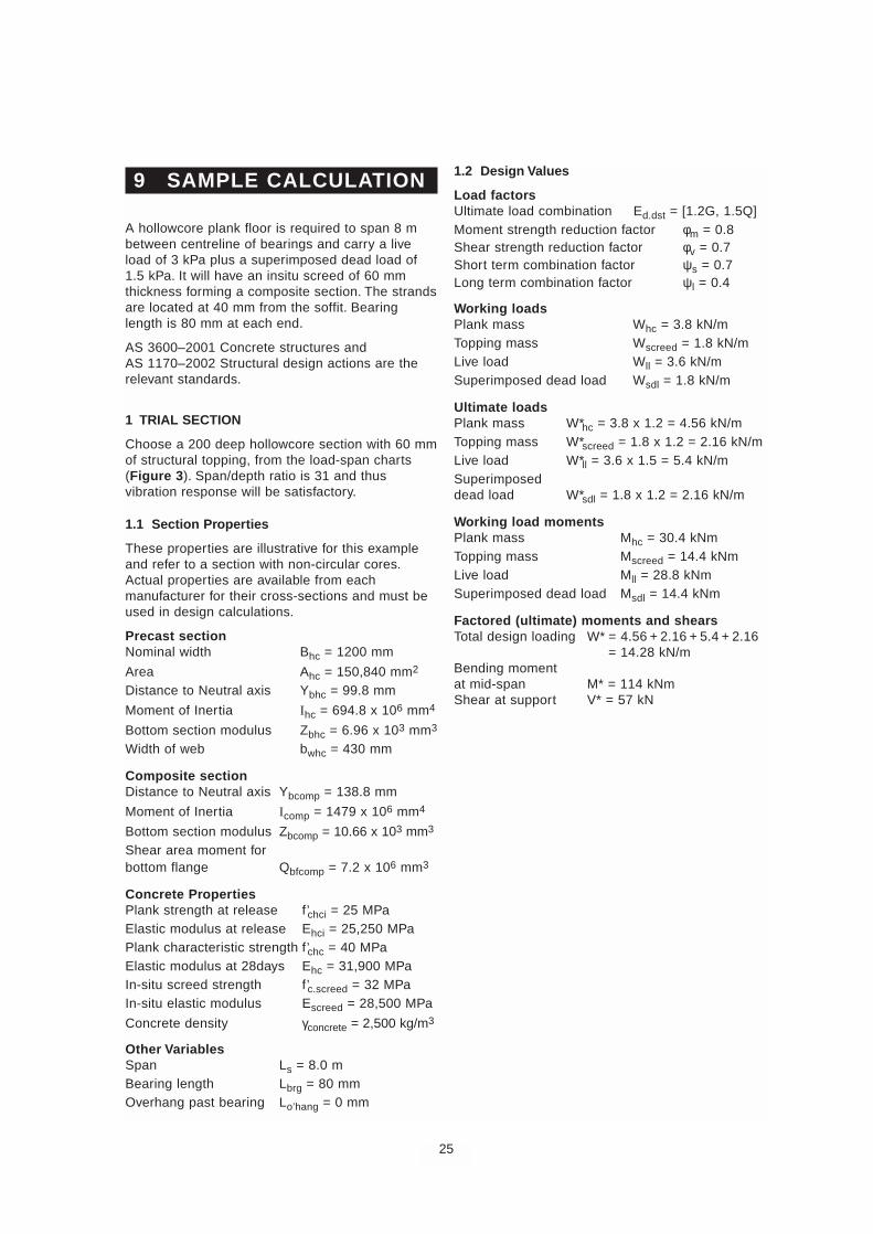
9 SAMPLE CALCULATION
A hollowcore plank floor is required to span 8 mbetween centreline of bearings and carry a liveload of 3 kPa plus a superimposed dead load of1.5 kPa. It will have an insitu screed of 60 mmthickness forming a composite section. The strandsare located at 40 mm from the soffit. Bearinglength is 80 mm at each end.
AS 3600–2001 Concrete structures andAS 1170–2002 Structural design actions are therelevant standards.
1 TRIAL SECTION
Choose a 200 deep hollowcore section with 60 mmof structural topping, from the load-span charts(Figure 3). Span/depth ratio is 31 and thusvibration response will be satisfactory.
1.1 Section Properties
These properties are illustrative for this exampleand refer to a section with non-circular cores.Actual properties are available from eachmanufacturer for their cross-sections and must beused in design calculations.
Precast sectionNominal width Bhc = 1200 mm
Area Ahc = 150,840 mm2
Distance to Neutral axis Ybhc = 99.8 mm
Moment of Inertia Ihc = 694.8 x 106 mm4
Bottom section modulus Zbhc = 6.96 x 103 mm3
Width of web bwhc = 430 mm
Composite sectionDistance to Neutral axis Ybcomp = 138.8 mm
Moment of Inertia Icomp = 1479 x 106 mm4
Bottom section modulus Zbcomp = 10.66 x 103 mm3
Shear area moment forbottom flange Qbfcomp = 7.2 x 106 mm3
Concrete PropertiesPlank strength at release f’chci = 25 MPaElastic modulus at release Ehci = 25,250 MPaPlank characteristic strength f’chc = 40 MPaElastic modulus at 28days Ehc = 31,900 MPaIn-situ screed strength f’c.screed = 32 MPaIn-situ elastic modulus Escreed = 28,500 MPa
Concrete density γconcrete = 2,500 kg/m3
Other VariablesSpan Ls = 8.0 mBearing length Lbrg = 80 mmOverhang past bearing Lo’hang = 0 mm
1.2 Design Values
Load factorsUltimate load combination Ed.dst = [1.2G, 1.5Q]Moment strength reduction factor φm = 0.8Shear strength reduction factor φv = 0.7Short term combination factor ψs = 0.7Long term combination factor ψl = 0.4
Working loadsPlank mass Whc = 3.8 kN/mTopping mass Wscreed = 1.8 kN/mLive load Wll = 3.6 kN/mSuperimposed dead load Wsdl = 1.8 kN/m
Ultimate loadsPlank mass W*hc = 3.8 x 1.2 = 4.56 kN/mTopping mass W*screed = 1.8 x 1.2 = 2.16 kN/mLive load W*ll = 3.6 x 1.5 = 5.4 kN/mSuperimposeddead load W*sdl = 1.8 x 1.2 = 2.16 kN/m
Working load momentsPlank mass Mhc = 30.4 kNmTopping mass Mscreed = 14.4 kNmLive load Mll = 28.8 kNmSuperimposed dead load Msdl = 14.4 kNm
Factored (ultimate) moments and shearsTotal design loading W* = 4.56 + 2.16 + 5.4 + 2.16
= 14.28 kN/mBending momentat mid-span M* = 114 kNmShear at support V* = 57 kN
25
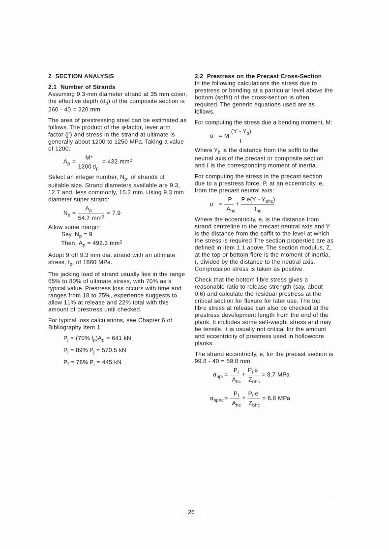
2 SECTION ANALYSIS
2.1 Number of StrandsAssuming 9.3-mm diameter strand at 35 mm cover,the effective depth (dp) of the composite section is260 - 40 = 220 mm.
The area of prestressing steel can be estimated asfollows. The product of the φ-factor, lever armfactor (j’) and stress in the strand at ultimate isgenerally about 1200 to 1250 MPa. Taking a valueof 1200:
Ap =M*
= 432 mm21200 dp
Select an integer number, Np, of strands ofsuitable size. Strand diameters available are 9.3,12.7 and, less commonly, 15.2 mm. Using 9.3 mmdiameter super strand:
Np = Ap = 7.9
54.7 mm2
Allow some marginSay, Np = 9
Then, Ap = 492.3 mm2
Adopt 9 off 9.3 mm dia. strand with an ultimatestress, fp, of 1860 MPa.
The jacking load of strand usually lies in the range65% to 80% of ultimate stress, with 70% as atypical value. Prestress loss occurs with time andranges from 18 to 25%, experience suggests toallow 11% at release and 22% total with thisamount of prestress until checked.
For typical loss calculations, see Chapter 6 ofBibliography Item 1.
Pj = (70% fp)Ap = 641 kN
Pi = 89% Pj = 570.5 kN
Pf = 78% Pi = 445 kN
2.2 Prestress on the Precast Cross-SectionIn the following calculations the stress due toprestress or bending at a particular level above thebottom (soffit) of the cross-section is oftenrequired. The generic equations used are asfollows.
For computing the stress due a bending moment, M:
σ = M (Y - Yb)
I
Where Yb is the distance from the soffit to theneutral axis of the precast or composite sectionand I is the corresponding moment of inertia.
For computing the stress in the precast sectiondue to a prestress force, P, at an eccentricity, e,from the precast neutral axis:
σ = P
+ P e(Y - Ybhc)
Ahc Ihc
Where the eccentricity, e, is the distance fromstrand centreline to the precast neutral axis and Yis the distance from the soffit to the level at whichthe stress is required The section properties are asdefined in item 1.1 above. The section modulus, Z,at the top or bottom fibre is the moment of inertia,I, divided by the distance to the neutral axis.Compression stress is taken as positive.
Check that the bottom fibre stress gives areasonable ratio to release strength (say, about0.6) and calculate the residual prestress at thecritical section for flexure for later use. The topfibre stress at release can also be checked at theprestress development length from the end of theplank. It includes some self-weight stress and maybe tensile. It is usually not critical for the amountand eccentricity of prestress used in hollowcoreplanks.
The strand eccentricity, e, for the precast section is99.8 - 40 = 59.8 mm.
σbpi = Pi +
Pi e = 8.7 MPa
Ahc Zbhc
σbphc= Pf +
Pf e = 6.8 MPa
Ahc Zbhc
26
+
+
+
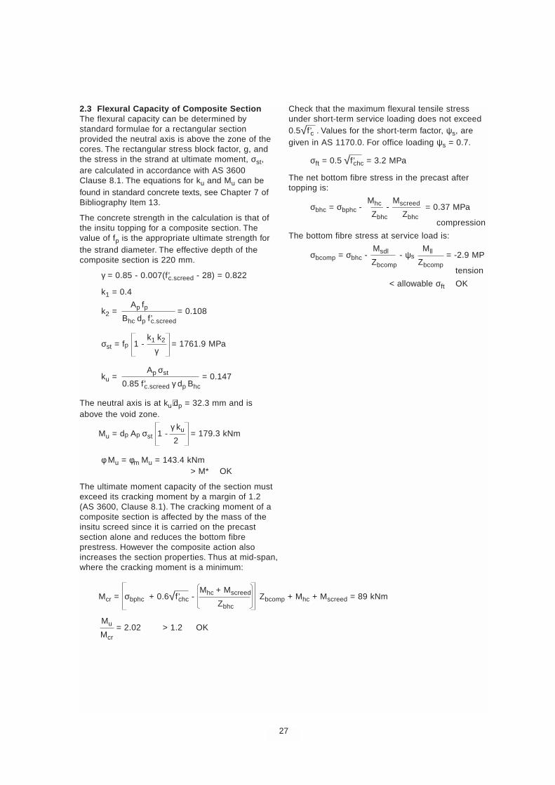
2.3 Flexural Capacity of Composite SectionThe flexural capacity can be determined bystandard formulae for a rectangular sectionprovided the neutral axis is above the zone of thecores. The rectangular stress block factor, g, andthe stress in the strand at ultimate moment, σst,are calculated in accordance with AS 3600Clause 8.1. The equations for ku and Mu can befound in standard concrete texts, see Chapter 7 ofBibliography Item 13.
The concrete strength in the calculation is that ofthe insitu topping for a composite section. Thevalue of fp is the appropriate ultimate strength forthe strand diameter. The effective depth of thecomposite section is 220 mm.
γ = 0.85 - 0.007(f’c.screed - 28) = 0.822
k1 = 0.4
k2 = Ap fp = 0.108
Bhc dp f’c.screed
σst = fp 1 - k1 k2 = 1761.9 MPa
γ
ku = Ap σst = 0.147
0.85 f’c.screed γ dp Bhc
The neutral axis is at ku⋅dp = 32.3 mm and isabove the void zone.
Mu = dp Ap σst 1 - γ ku = 179.3 kNm2
φMu = φm Mu = 143.4 kNm> M* OK
The ultimate moment capacity of the section mustexceed its cracking moment by a margin of 1.2(AS 3600, Clause 8.1). The cracking moment of acomposite section is affected by the mass of theinsitu screed since it is carried on the precastsection alone and reduces the bottom fibreprestress. However the composite action alsoincreases the section properties. Thus at mid-span,where the cracking moment is a minimum:
Mu = 2.02 > 1.2 OKMcr
Check that the maximum flexural tensile stressunder short-term service loading does not exceed0.5√f’c . Values for the short-term factor, ψs, aregiven in AS 1170.0. For office loading ψs = 0.7.
σft = 0.5 √f’chc = 3.2 MPa
The net bottom fibre stress in the precast aftertopping is:
σbhc = σbphc -Mhc -
Mscreed = 0.37 MPaZbhc Zbhc
compression
The bottom fibre stress at service load is:
σbcomp = σbhc -Msdl - ψs
Mll = -2.9 MPZbcomp Zbcomp
tension
< allowable σft OK
27
Mcr = σbphc + 0.6√f’chc - Mhc + Mscreed Zbcomp + Mhc + Mscreed = 89 kNm
Zbhc
-
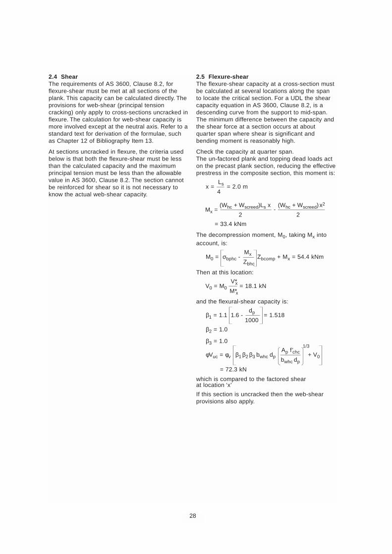
2.4 ShearThe requirements of AS 3600, Clause 8.2, forflexure-shear must be met at all sections of theplank. This capacity can be calculated directly. Theprovisions for web-shear (principal tensioncracking) only apply to cross-sections uncracked inflexure. The calculation for web-shear capacity ismore involved except at the neutral axis. Refer to astandard text for derivation of the formulae, suchas Chapter 12 of Bibliography Item 13.
At sections uncracked in flexure, the criteria usedbelow is that both the flexure-shear must be lessthan the calculated capacity and the maximumprincipal tension must be less than the allowablevalue in AS 3600, Clause 8.2. The section cannotbe reinforced for shear so it is not necessary toknow the actual web-shear capacity.
2.5 Flexure-shearThe flexure-shear capacity at a cross-section mustbe calculated at several locations along the spanto locate the critical section. For a UDL the shearcapacity equation in AS 3600, Clause 8.2, is adescending curve from the support to mid-span.The minimum difference between the capacity andthe shear force at a section occurs at aboutquarter span where shear is significant andbending moment is reasonably high.
Check the capacity at quarter span.The un-factored plank and topping dead loads acton the precast plank section, reducing the effectiveprestress in the composite section, this moment is:
x = Ls = 2.0 m4
Mx = (Whc + Wscreed)Ls x (Whc + Wscreed) x2
2 2
= 33.4 kNm
The decompression moment, M0, taking Mx intoaccount, is:
M0 = σbphc -Mx Zbcomp + Mx = 54.4 kNmZbhc
Then at this location:
V0 = M0V*x = 18.1 kNM*x
and the flexural-shear capacity is:
β1 = 1.1 1.6 - dp = 1.518
1000
β2 = 1.0
β3 = 1.0
φVuc = φv β1 β2 β3 bwhc dpAp f’chc
1/3
+ V0bwhc dp
= 72.3 kN
which is compared to the factored shearat location ‘x’
If this section is uncracked then the web-shearprovisions also apply.
28
-
2.6 Web-shearThe principal tension under the design loading at across-section is limited to 0.33√f’chc by AS 3600,Clause 8.2. It is not obvious where the maximumvalue will occur and a number of locations in thesection will require examination. These include theminimum web width, the neutral axis and thebottom web-flange junction. The latter only appliesto planks with non-circular voids. At positions otherthan the neutral axis there will be flexural stress onthe cross-section due to superimposed loads inaddition to the self weight and prestress.
The critical section for web-shear is likely to be atdp from the support. In a hollowcore plank thissection will almost always be within thedevelopment length of the strand where shear is ata maximum and the prestress will be less than thefull amount.
Check intersection of web and bottom flange.As an example, check the intersection of web andbottom flange at a section located at the effectivedepth from the support. There are corner filletscommencing at 85 mm from the soffit.
The development length of a strand is 60diameters. The available prestress developmentlength, Ld, from the end of the plank to the sectionincludes the bearing length and any overhangbeyond the bearing.
Ld = dp + Lbrg + Lo’hang = 300 mm≤ 60 strand diameters
The first 10% of the total development length isassumed to be unstressed (AS 3600, Clause 13.3).Thus the prestress force at a section within thedevelopment length is:
Px = Ld - 0.1(60 db)
Pf = 216.4 kN0.9(60db)
The maximum allowable principal tension is:
σp = 0.33 √f’chc = 2.087 MPa
Location of section from centre of support is:
x = dp + Lbrg = 260 mm2
Factored shear and moments here are:
V*x = V* - W* x = 53.3 kN
M*xhc = (W*hc + W*sdl) x
(Ls - x) = 6.7 kNm2
M*x = (W*ll + W*sdl) x
(Ls - x) = 7.6 kNm2
The section is uncracked, hence web-shearprovisions apply.
Y = 85 mm
bv = bwhc
σs = V*x Qbfcomp = 0.6 MPa
Icomp bv
σpx = σx
2
+ σs2 -
σx = 0.24 MPa√ 2 2
tension< σp OK
The web width, bv, is the total width across theplank at the level being considered, in this casebelow the flange fillet. Q is the first moment aboutthe neutral axis of the cross-section area belowthat level. Note that compressive direct stress ispositive in the above equations. The flexure-shearcapacity must also be checked.
2.7 Interface shearCheck the interface shear (AS 3600, Clause 8.4)between the topping and the plank, using theappropriate surface roughness, in this caseassume a smooth machine-screeded surface.
β5 = 0.2
fct = 0.4 √f’c.screed = 2.3 MPa
φVuf = φv β5 Bhc dp fct = 83.6 kN> V* OK
29
Direct stress at this location is:
σx = Px - Px e
Y - Ybhc + M*xhcY - Ybhc + M*x
Y - Ybcomp
Ahc Ihc Ihc Icomp
= 1.29 MPacompression
30
2.8 DeflectionCalculate the deflection of the plank at installationand under long-term service load using thedeflection multipliers from Table 3 in BibliographyItem 12 (reproduced below). The insitu toppingprovides a level surface initially and is the datumfrom which subsequent deflections are measured.Downward deflection is negative in thesecalculations.
The hog due to prestress at release is:
∆ps = Pi e Ls
2
= 15.6 mm8Ehci Ihc
The self-weight deflection is:
∆hc = -5 Whc Ls
4
= - 11.5 mm384 Ehci Ihc
at release the plank has a net hog upwards of4.1 mm.
The deflection components for the insitu topping,superimposed dead load and live load are:
∆screed = -5 Wscreed Ls
4
= - 4.3 mm384 Ehc Ihc
∆sdl = -5 Wsdl Ls
4
= - 2.3 mm384 Escreed Icomp
∆ll = -5 Wll Ls
4
= - 4.5 mm384 Escreed Icomp
At erection, the hog of the plank is:
∆erection = 1.8 ∆ps + 1.85 ∆hc = 6.8 mm
Immediately after pouring the screed, the soffit ofthe plank is at:
∆erection + ∆screed = 2.5 mm
The long-term service load deflection of the datumtop screed surface has only the long-termcomponents of the multipliers for the prestress,plank mass and topping mass in the deflectioncalculation. Therefore the elastic deflectioncomponent must be subtracted from the multipliersin the Table (below), e.g. for ∆ps the long-termcomponent of the multiplier for a composite unit is2.2 -1 = 1.2. Values for the long-term load factor,ψl, are given in AS 1170.0. For office loadingψl = 0.4.
∆top.surface = (1.2 ∆ps + 1.4 ∆hc + 1.3 ∆screed) +3.0 ∆sdl + 3.0 ψl ∆ll
= - 15.3 mm
The span/deflection ratio is:
Ls = 524- ∆top.surface
Suggested Multipliers for Estimating Long-term Cambers and Deflections for Typical Elements[Based on Table 3 in Bibliography Item 12]
Composite toppingStage Component Application Without With
Erection Deflection (downward) Elastic deflection due to element mass at release of prestress 1.85 1.85
Erection Camber (upward) Elastic camber due to prestress at time of release of prestress 1.80 1.80
Final Deflection (downward) Elastic deflection due to element mass at release of prestress 2.70 2.40
Final Camber (upward) Elastic camber due to prestress at time of release of prestress 2.45 2.20
Final Deflection (downward) Elastic deflection due only to superimposed dead load or tolong-term live load 3.00 3.00
Final Deflection (downward) Elastic deflection caused by the composite topping – 2.30
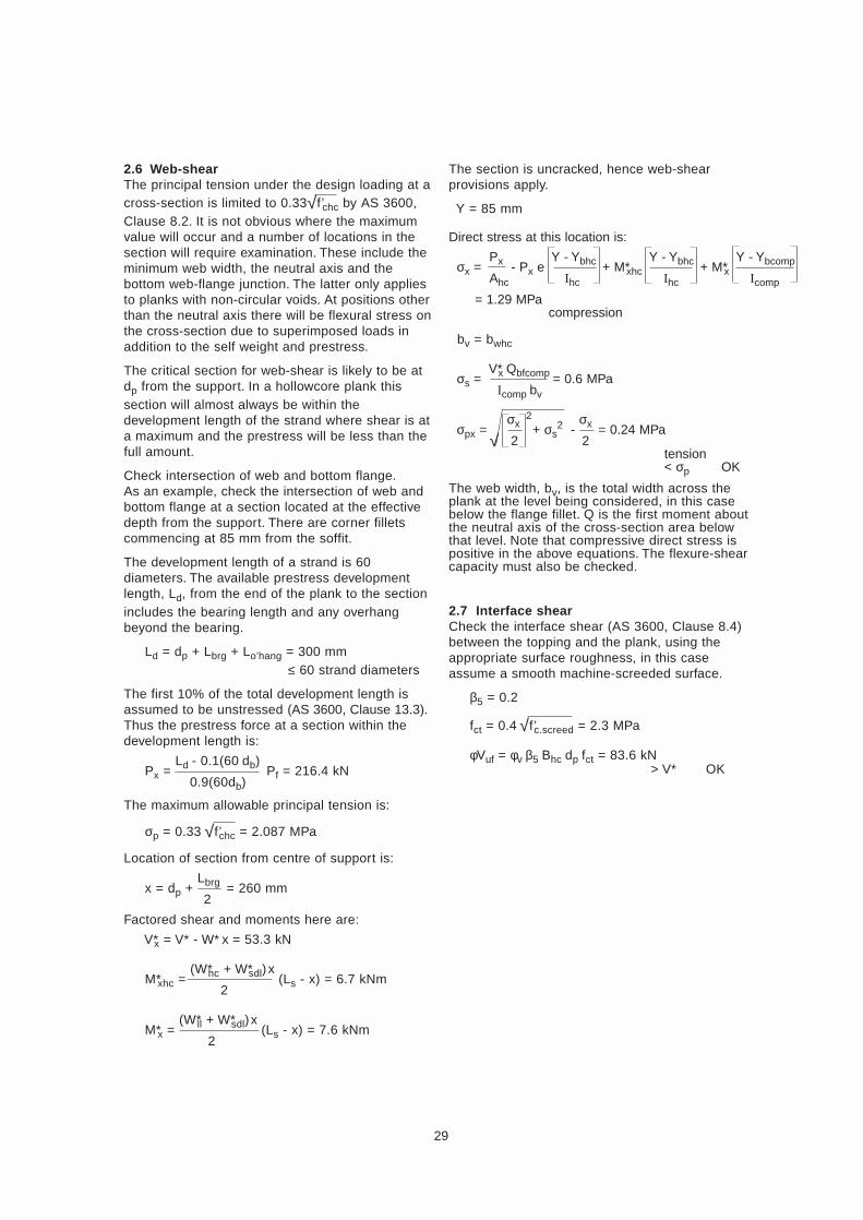
Core break-outs areused to grout inintegrity ties, seeFigure 13 (page 13)
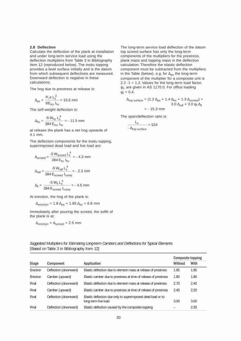
Penetrations for servicesand provision for hangersare readily accommodatedby hollowcore planks, seeFigure 19 (page 20) andFigure 21 (page 21)
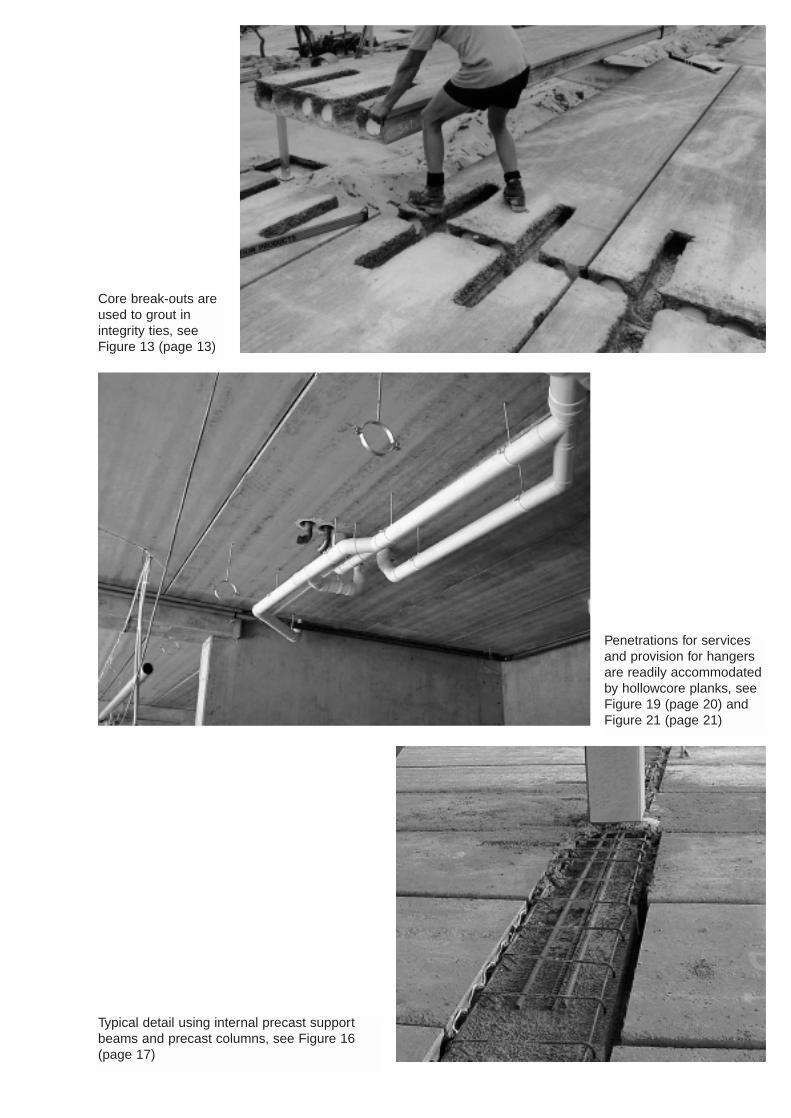
Typical detail using internal precast supportbeams and precast columns, see Figure 16(page 17)

Hollowcore Floor Planks may be supported on precastbeams (above) or masonry walls (below) as detailed inFigure 16 (page 17)
Hollowcore Floor Planks may be supported on precastwalls (above) as detailed in Figure 16 (page 17) orsteelwork (below) as detailed in Figure 17 (page 18)
Topping concrete is often used to produce compositeunits and a level floor surface, see Figure 1 (page 5)
Hollowcore Floor Planks are idealfor residential construction. Theyeasily accommodate set-downsfor wet areas, penetrations forservices and step-downs forbalconies

Hollowcore Floor Planks are becoming the preferred flooring system for many multi-storey projectsbecause of their distinctive advantages (see Page 2)
MANUFACTURERS OF HOLLOWCORE PRODUCTS:
Delta Corporation Ltd Hollow Core Concrete Pty Ltd218 Campersic Road 12–14 Maria StreetHerne Hill WA 6056 Laverton North VIC 3026Phone: 08 9296 4111 Fax: 08 9296 1184 Phone: 03 9369 4944 Fax: 03 9369 2025Email: [email protected] Email: [email protected]
Rescrete Industries Westkon Precast Concrete Pty LtdPO Box 121 PO Box 371Riverstone NSW 2765 Sunshine VIC 3020Phone: 02 9627 2666 Fax: 02 9627 5161 Phone: 03 9312 3688 Fax: 03 9312 1735Email: [email protected] Email: [email protected]
For other information on hollowcore, see the NPCAA web site: www.npcaa.com.au ISB
N 0
957
7467
2 5
Des
igne
d an
d pr
oduc
ed b
y Te
chM
edia
Pub
lishi
ng P
ty L
td
02 9
477
7766

![DESIGNING COMPOSITE BEAMS WITH PRECAST HOLLOWCORE SLABS …ascjournal.com/down/vol3no2/vol3no2_6.pdf · DESIGNING COMPOSITE BEAMS WITH PRECAST HOLLOWCORE SLABS ... 2 [5] for concrete](https://img.pdfslide.us/doc/110x75/5a71d9b57f8b9ab6538d11c2/designing-composite-beams-with-precast-hollowcore-slabs-ascjournalcomdownvol3no2vol3no26pdfpdf.jpg)