Embed Size (px)
Citation preview
CPI – Concrete Plant International –1 | 2010 www.cpi-worldwide.com182
PRECAST CONCRETE ELEMENTS
Arnold Van Acker, Past-chairman fib Commission on Prefabrication, Belgium
The fire resistance of a concrete structureexposed to fire is a very complex pheome-non, whether it is a cast-in-situ structure or aprecast one. This is due to the large numberof parameters intervening, and all possiblevariations thereof. In the first place, there isthe intensity of the fire, depending amongothers on the actual fire load and the com-bustibility of the materials.
Also the air supply is crucial, since combus -tion needs oxygen. Another parameter con-cerns the location of the fire within the struc-ture, the size of the building and the exten-sion of the fire. Also the structural lay-outand dimensions of the building and thecomponents are influencing the stabilityduring a fire. And finally there are thedimensions of the elements, the concretecomposition, moisture content of the harden ed concrete, axis distance to thereinforcement, etc.
During the last decade, the knowledgeabout the phenomenon playing a role inthe shear capacity of hollowcore floors hasincreased drastically. Unfortunately it is notalways known to all designers. In the framework of the European Standardisa -
tion, a Task Group has been established acouple of years ago, to redraft the annex G“ Fire resistance” of the Product StandardEN 1168 on hollowcore units. The tabulated values related to minimumslab thickness and axis distance of the rein-forcement, given in the previous publication,were considered unconservative and alsothe requirements on shear capacity wereinsufficient.
This paper provides a detailed analysis ofthe effect of fire on prestressed hollowcorefloors and explains the important role of theconnections with the supporting structure inthe shear capacity at fire. A new calculationmethod for the shear resistance of prestressedhollow core floors is explained.
Phenomenon
When a concrete structure is exposed toheavy fire, two phenomenon occur simulta-neously: a reduction of the material perfor-mances and a thermal expansion. The firstphenomenon is well known and constitutesat present the basis for the fire design. Itfocusses primarily on minimum dimensionsof the cross-section of the components andminimum axis distance of the reinforcement.The second phenomenon is less known andalso much more complex. Thermal expan -
sions occur not only in all directions but alsoover the cross-section of the components.As a consequence, induced thermal stressesmay occur the magnitude of which depend -ing on the size of the building, the stabilityconcept, the structural lay-out , shape andcross-section of the units, etc.
At real fires in concrete structures, it is statedthat collapse seldom occurs because of thedecrease of the material performances atelevated temperatures, but nearly alwaysbecause of the incompatibility of the struc-ture to cope with important thermal defor-mations. Fortunately, concrete structurespossess not only a high fire resistance, butalso a large resilience because of its robust-ness and the possibility to redistribute theacting loading. Failures due to fire are sel-dom occuring in concrete structures. This isalso the case for precast hollowcore floors.
Thermal expansion
When a fire occurs in the central part of alarge floor, the thermal expansion of theunits will be almost completely restrainedby the rigidity of the surrounding floor. Therestrainment will mobilise important com-pressive forces in the fire exposed floorunits. This was for example demonstratedduring a real fire in a small storage room in
Fire safety of prestressed hollowcore floors Shear capacity of hollowcore floors
Prestressed hollowcore units are now the most widely used type of precast flooring in Western Europe. This success is largely due to thehighly efficient design and production methods, flexibility in use, surface finish and structural efficiency. However, some concern has beenrecently raised about the actual performance of hollowcore floors in fire, following some limited calamities in a few real fires. Also a fewcases of premature shear failure in small scale standard fire tests were reported in the past. Henceforth, the question could be raised if thisconstitutes a real structural problem for this type of floor, or whether the reason lies in a lack of understanding of the behaviour of hollowcoreslabs during heavy fire, resulting in poor design, also for small-scale laboratory test set-ups.
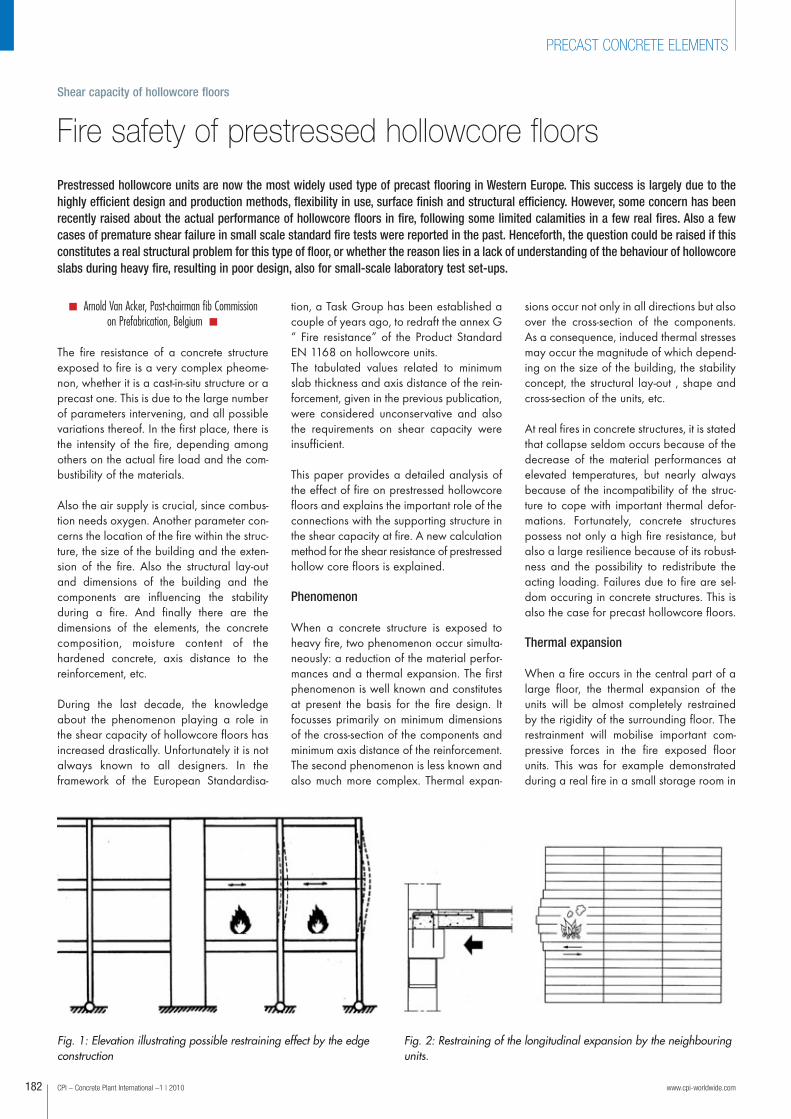
Fig. 1: Elevation illustrating possible restraining effect by the edgeconstruction
Fig. 2: Restraining of the longitudinal expansion by the neighbouringunits.
06a-Fertigteile_166-199_en.qxp:Layout 1 25.01.2010 11:35 Uhr Seite 182
the middle of a large multi-storey building under construction. Due to the heavy fire of some barrels with fuel, extreme high localtemperatures arised. The thermal expansion of the hollowcore floorabove the fire was completely restrained by the surrounding coldfloor. Due to the induced compressive force, large concrete spallingoccurred in the underflange of a few floor units.
When a fire occurs at the edge of a floor, some restraining effectmay also be generated through the rigidity of the edge construction.In the example of Figure 1, the thermal expansion of the floor abovethe fire is restrained by the edge column via the supporting beam,
www.cpi-worldwide.com CPI – Concrete Plant International –1 | 2010
PRECAST CONCRETE ELEMENTS
Arnold Van Acker, born 1936, Master of Civil Engineering, Tech ni calUniversity, Ghent, Belgium. He has been working for 44 years in the pre-cast concrete industry, mainly in research and development of precastconcrete products and structures, and for European Standardisation(Eurocodes and CEN Product Standards). Retired since 2001, he is stillvery active in prefabrication, among other activities as an expert of theBelgian Precast Concrete Federation (FeBe). He has recently written a lec-
ture course on the design of precast concrete structures – 11 lessons – design ed to be a modelcourse for university professors to instruct students of engineering and archi tec ture in the fieldof precast concrete construction. Member of the International Concrete Federation fib –Commission on Pre fabri ca tion – since 1978 and chairman of the Com miss ion from 1986 till2002. Mr. Van Acker was awarded the FIP medal for outstanding contributions to the develop-ment of prestressed and precast concrete. He also received awards from the “Inter nationalFederation of Precast Concrete” BIBM, from the “European Committee for Standard isation” CEN,and from other Belgian and international organizations. He is internationally well known onaccount of his numerous publications and partici pation in conferences all over the world.
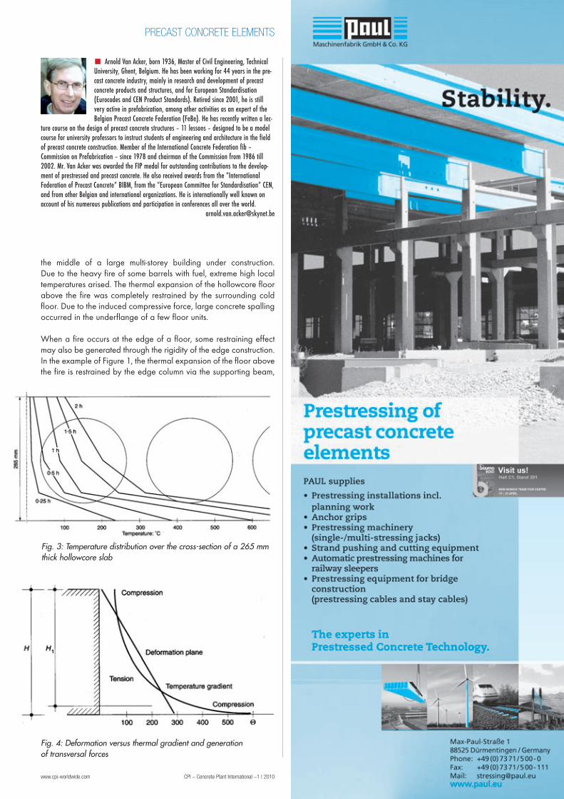
Fig. 3: Temperature distribution over the cross-section of a 265 mmthick hollowcore slab
Fig. 4: Deformation versus thermal gradient and generation of transversal forces
06a-Fertigteile_166-199_en.qxp:Layout 1 25.01.2010 11:35 Uhr Seite 183
CPI – Concrete Plant International –1 | 2010 www.cpi-worldwide.com184
PRECAST CONCRETE ELEMENTS
which transfers the induced horizontal forceto the floor structure above and below thefire-exposed floor. In case of a local fire atan edge bay of a building, the not exposed
surrounding floor itself may also contributeto the restraint to expansion. Due to the rein-forced structural topping and the transver-sal tie-reinforcement at the support zone,the floor is acting as a coherent diaphragm.Any expansion of a floor unit or a floorzone, will be restrained by the not exposedneighbouring units. The force is transferredpartially via the longitudinal joints, (shearforce capacity 0.25 to 0.40 N/mm² [4]),and partially through the reinforced top-ping and the transversal tie reinforcementwith the edge structure.
Heavy heating of the underside of a floormay also lead to lateral expansion of the
units. However, just as in the longitudinaldirection, this lateral expansion of the bottomflange will be restrained by the surroundingstructure in a more or less important way,depending on the structural lay-out. Slabslocated in the middle of a large floor will becompletely restrained by the surroundingfloor structure. Slabs located at the edgesof the floor will undergo a smaller trans ver-sal restrainment, and the thermal expansionof the bottom flange may accumulate at theexterior slabs, and hence increase the trans-versal shear in the webs. Indeed, duringstandard fire tests, small horizontal crackshave been stated a few times in the outmostwebs of the floor set-up, due to the diffe-
Stress in N/mm
Sla
b t
hic
kn
ess 2
6 m
m
30 minutes 60 minutes
120 minutes
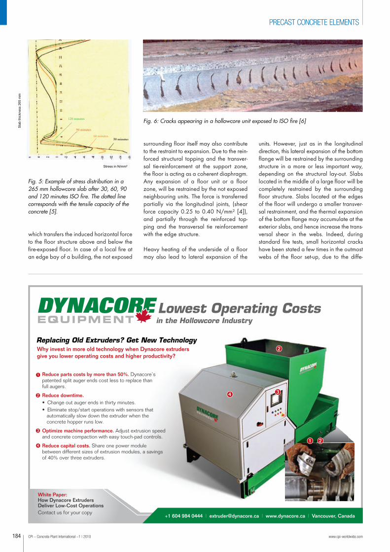
Fig. 5: Example of stress distribution in a265 mm hollowcore slab after 30, 60, 90and 120 minutes ISO fire. The dotted linecorresponds with the tensile capacity of theconcrete [5].
Fig. 6: Cracks appearing in a hollowcore unit exposed to ISO fire [6]
PRECAST CONCRETE ELEMENTS
06a-Fertigteile_166-199_en.qxp:Layout 1 25.01.2010 11:36 Uhr Seite 184

rential expansion between the top flangeand the bottom flange, especially in slabswith a reinforced structural topping. How -ever, in most fire tests, the differential lateralexpansion results in vertical cracks at thecores in the longitudinal direction throughthe slab, because of the weaker cross-sectionof the top and bottom flanges compared tothe webs. In neither of the observed cases,
those cracks were leading to failure of thetest floor, even after 150 minutes ISO fireexposure.
Induced thermal stresses
Hollowcore units exposed to fire are sub-jected to induced thermal stresses over theircross-section. Measurements during lSO
fire tests show that the temperature gradienthas a strong curvature. Figure 3 shows theregistered temperatures over the cross-sectionof a 265 mm thick slab respectively after30, 60, 90 and 120 minutes of exposure. Itcan be seen that after 30 minutes the cur-vature of the temperature profile is strongerthan for other fire exposure time. Due to the typical non-linear thermal gradient through the hollowcore slab, andthe fact that plane sections must remainplaine, thermal stresses are inducedthrough the cross-section as shown in Figure 4. The following distribution of thermal stressesis shown: compression at the bottom of theslab, changing rapidly into tension higherup. Further upwards, the tensile capacity ofthe concrete is reached and the concrete iscracking. Still more upwards, the concreteis again subjected to tension and further upto compression in the top section. Calculations shown that the tensile stressesin the central zone are exceeding the tensilecapacity of the concrete after about 20 to40 minutes, and that vertical cracks areappearing at regular intervals, situated at adistance of about 150 to 200 mm to eachother. The results of a calculation example
PRECAST CONCRETE ELEMENTS
Dis
tan
ce
fro
m t
he
bo
tto
m in
cm
Sla
b t
hic
kn
ess
Compression
Tension
Appearance of horizontal
shear stresses in the cross
section
Fig. 7: Illustration of horizontal shear stresses in the cross-section of a hollow core unit
06a-Fertigteile_166-199_en.qxp:Layout 1 25.01.2010 11:36 Uhr Seite 185
CPI – Concrete Plant International –1 | 2010 www.cpi-worldwide.com186
PRECAST CONCRETE ELEMENTS
are given on Figure 5. The calculationswere carried out by the Department ofMechanics and Civil Engineering of theUniversity of Liège in Belgium [5]. The com-pressive stresses in the underflange of a265 mm thick hollowcore slab were in theorder of 8 to 16 N/mm². Figure 6 showsthe cracks in the web of a longitudinally cutted hollow core slab during a fire test atthe laboratory of TNO in Delft, The Nether -lands [6].
The reason for the distribution of the cracksover the whole length lies in the fact that theinduced tensile stresses are appearing overthe whole length of the slab. Since they arelarger than the tensile capacity of the con-crete, the webs will crack. At the crack thetensile stress drops to zero, but outside thecrack it will again built up until it reachesagain the tensile strength of the concrete.This happens at intervals of 150 to 200 mm.
Another consequence of the above mention -ed stress distribution over the slab height isthe appearance of shear stresses in the tran-sition zone between the induced thermal
compressive and tensile forces. Finally thereare also the normal shear stresses due tothe self weight and the variable loading ofthe slabs.To sum up, the following complex stresssituation is acting over the cross-section of ahollowcore unit exposed to ISO fire:
· Induced thermal strsses causing verticalcracks in the webs at regular intervals,in combination with horizontal tensilestresses inbetween the cracks;
· Horizontal shear stresses of thermal origin in the lower part of the cross-sec-tion, as a consequence of the transitionof compressive forces into tensile forces
· Shear stresses in the webs due to theself weight and imposed loading of theslab;
· Shear stresses due to the introduction ofthe prestressing force at the slab end
Moment restrained floor support
During a fire, simply supported hollowcorefloors will deflect because of the expansionof the bottom fibres. In a floor with moment
restrained supports, the deflection will belimited by the top reinforcement.
Hence, the support moment will increase asa function of the amount of reinforcement(Figure 8). Additional compressive forceswill develop in the bottom flange of thefloor units in the vicinity of the supports. Forthis reason, restrained supports of hollow -core floors are not recommended.
Failure mechanisms
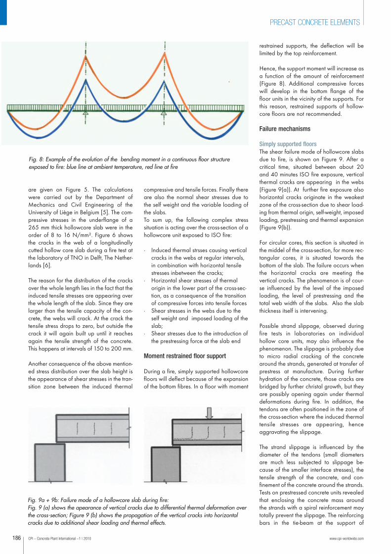
Simply supported floorsThe shear failure mode of hollowcore slabsdue to fire, is shown on Figure 9. After a critical time, situated between about 20and 40 minutes ISO fire exposure, verticalthermal cracks are appearing in the webs(Figure 9(a)). At further fire exposure alsohorizontal cracks originate in the weakestzone of the cross-section due to shear load -ing from thermal origin, self-weight, impos edloading, prestressing and thermal expansion(Figure 9(b)).
For circular cores, this section is situated inthe middel of the cross-section, for more rec-tangular cores, it is situated towards the bottom of the slab. The failure occurs whenthe horizontal cracks are meeting the vertical cracks. The phenomenon is of cour-se influenced by the level of the imposedloading, the level of prestressing and thetotal web width of the slabs. Also the slabthickness itself is intervening.
Possible strand slippage, observed duringfire tests in laboratories on individual hollow core units, may also influence thephenomenon. The slippage is probably dueto micro radial cracking of the concretearound the strands, generated at transfer ofprestress at manufacture. During furtherhydration of the concrete, those cracks arebridged by further christal growth, but theyare possibly opening again under thermaldeformations during fire. In addition, thetendons are often positioned in the zone ofthe cross-section where the induced thermaltensile stresses are appearing, henceaggravating the slippage.
The strand slippage is influenced by the diameter of the tendons (small diametersare much less subjected to slippage be -cause of the smaller interface stresses), thetensile strength of the concrete, and con -finement of the concrete around the strands.Tests on prestressed concrete units revealedthat enclosing the concrete mass aroundthe strands with a spiral reinforcement maytotally prevent the slippage. The reinforcingbars in the tie-beam at the support of
Fig. 8: Example of the evolution of the bending moment in a continuous floor structure exposed to fire: blue line at ambient temperature, red line at fire
Fig. 9a + 9b: Failure mode of a hollowcore slab during fire: Fig. 9 (a) shows the apearance of vertical cracks due to differential thermal deformation overthe cross-section; Figure 9 (b) shows the propagation of the vertical cracks into horizontalcracks due to additional shear loading and thermal effects.
06a-Fertigteile_166-199_en.qxp:Layout 1 25.01.2010 11:36 Uhr Seite 186
hollowcore slabs are to a certain extentacting as confinement to the concretearound the strands, since the cast in-situconcrete of the tie beam penetrates into thecores over 50 to 100 mm.
The hindered expansion of the surroundingstructure is also contributing in a positiveway to the anchorage of the prestressingtendons.
Floors with restrained supportsHollowcore slabs with moment restrainedsupports and/or restraint to the longitudinalexpansion, may fail during a heavy firebecause of excessive compressive stressesin the exposed underflange.
There are different possible causes, whichmay act separately or in combination. Thecompression stress should be limited to themean compressive strength of the concretein the underflange after θ minutes ISO fire(σd, θ ≤ f cd, θ ). The following causes maybe at the origin of the compressive stressesin the bottomflange:
· Compressive stresses due to the supportmoment
· Additional negative flexural momentsdue to the restrained thermal deflectionof the floor in the longitudinal directions
· Prestressing force· Compressive stresses due to the temper-
ture gradient over the cross-section· Compressive stresses due to restrain-
ment of the thermal expansion by thesurrounding structures
· Hindered vertical deformation becauseof a very stiff thick topping
Shear capacity of cracked concrete sections
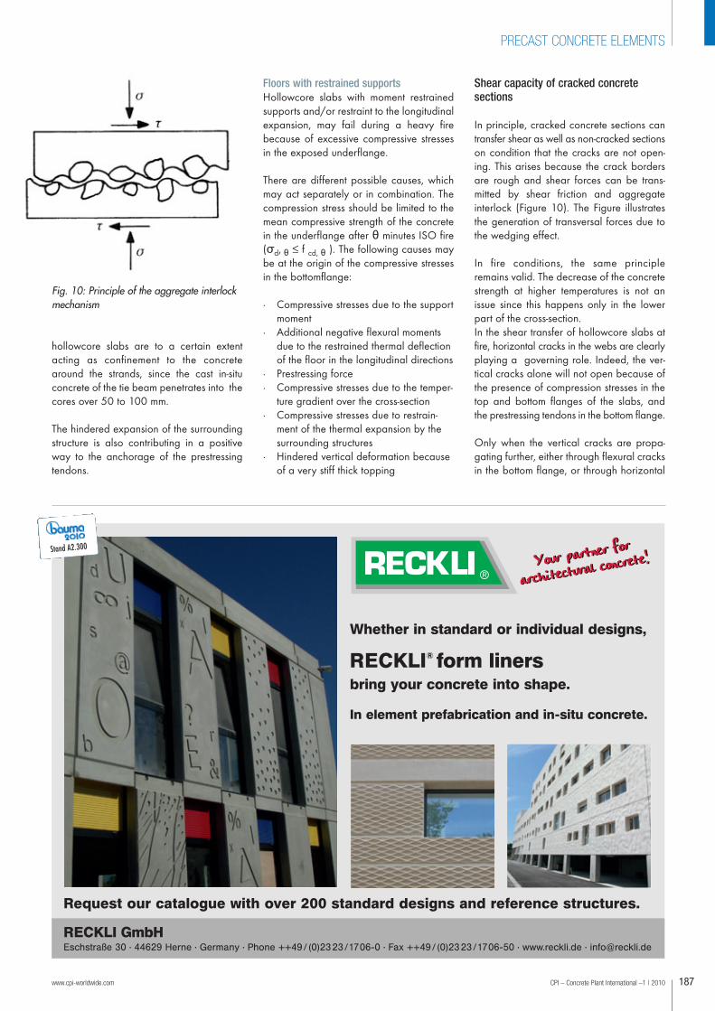
In principle, cracked concrete sections cantransfer shear as well as non-cracked sectionson condition that the cracks are not open -ing. This arises because the crack bordersare rough and shear forces can be trans-mitted by shear friction and aggregateinterlock (Figure 10). The Figure illustratesthe generation of transversal forces due tothe wedging effect.
In fire conditions, the same principleremains valid. The decrease of the concretestrength at higher temperatures is not anissue since this happens only in the lowerpart of the cross-section.In the shear transfer of hollowcore slabs atfire, horizontal cracks in the webs are clear lyplaying a governing role. Indeed, the ver-tical cracks alone will not open because ofthe presence of compression stresses in thetop and bottom flanges of the slabs, andthe prestressing tendons in the bottom flange.
Only when the vertical cracks are propa-gating further, either through flexural cracksin the bottom flange, or through horizontal
www.cpi-worldwide.com CPI – Concrete Plant International –1 | 2010 187
PRECAST CONCRETE ELEMENTS
Whether in standard or individual designs,
RECKLI® form linersbring your concrete into shape.
In element prefabrication and in-situ concrete.
Your partner for
architectural concrete!Your partner for
architectural concrete!
Request our catalogue with over 200 standard designs and reference structures.
RECKLI GmbHEschstraße 30 · 44629 Herne · Germany · Phone ++49/ (0)2323/1706-0 · Fax ++49/ (0)2323/1706-50 · www.reckli.de · [email protected]
Fig. 10: Principle of the aggregate interlockmechanism
Stand A2.300
06a-Fertigteile_166-199_en.qxp:Layout 1 25.01.2010 11:36 Uhr Seite 187
CPI – Concrete Plant International –1 | 2010 www.cpi-worldwide.com188
PRECAST CONCRETE ELEMENTS
cracks in the webs, the shear capacity becomes critical. However,as explained before, the web cross-section is usually much weakerthan the bottom flange, and cracks are thus propagating horizon-tally rather than vertically. This has also been stated during fire tests.The solution of the problem lies in the realisation of the aggregateinterlock effect through both horizontal and vertical cracks.
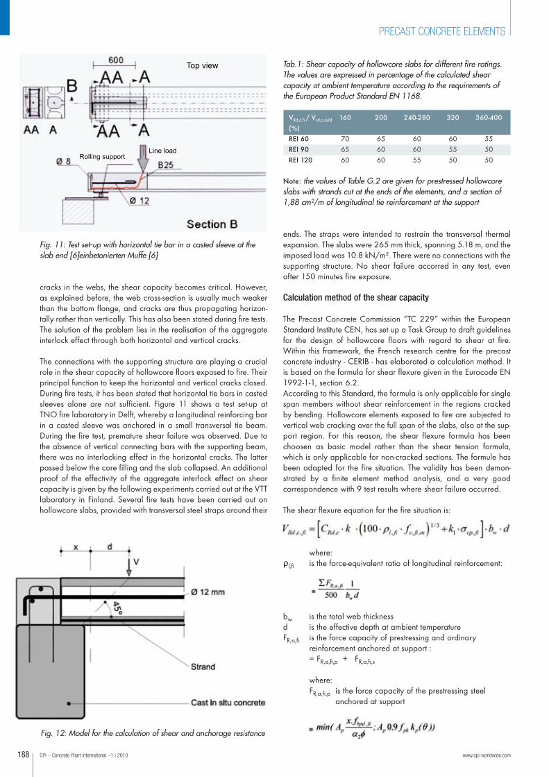
The connections with the supporting structure are playing a crucialrole in the shear capacity of hollowcore floors exposed to fire. Theirprincipal function to keep the horizontal and vertical cracks closed. During fire tests, it has been stated that horizontal tie bars in castedsleeves alone are not sufficient. Figure 11 shows a test set-up atTNO fire laboratory in Delft, whereby a longitudinal reinforcing barin a casted sleeve was anchored in a small transversal tie beam.During the fire test, premature shear failure was observed. Due tothe absence of vertical connecting bars with the supporting beam,there was no interlocking effect in the horizontal cracks. The latterpassed below the core filling and the slab collapsed. An additionalproof of the effectivity of the aggregate interlock effect on shearcapacity is given by the following experiments carried out at the VTTlaboratory in Finland. Several fire tests have been carried out onhollowcore slabs, provided with transversal steel straps around their
ends. The straps were intended to restrain the transversal thermalexpansion. The slabs were 265 mm thick, spanning 5.18 m, and theimposed load was 10.8 kN/m². There were no connections with thesupporting structure. No shear failure accorred in any test, evenafter 150 minutes fire exposure.
Calculation method of the shear capacity
The Precast Concrete Commission “TC 229” within the EuropeanStandard Institute CEN, has set up a Task Group to draft guidelinesfor the design of hollowcore floors with regard to shear at fire.Within this framework, the French research centre for the precastconcrete industry - CERIB - has elaborated a calculation method. Itis based on the formula for shear flexure given in the Eurocode EN1992-1-1, section 6.2. According to this Standard, the formula is only applicable for singlespan members without shear reinforcement in the regions crackedby bending. Hollowcore elements exposed to fire are subjected tovertical web cracking over the full span of the slabs, also at the sup-port region. For this reason, the shear flexure formula has beenchoosen as basic model rather than the shear tension formula,which is only applicable for non-cracked sections. The formule hasbeen adapted for the fire situation. The validity has been demon-strated by a finite element method analysis, and a very good correspondence with 9 test results where shear failure occurred.
The shear flexure equation for the fire situation is:
where:ρl,fi is the force-equivalent ratio of longitudinal reinforcement:
bw is the total web thicknessd is the effective depth at ambient temperatureFR,a,fi is the force capacity of prestressing and ordinary
reinforcement anchored at support : = FR,a,fi,p + FR,a,fi,s
where:FR,a,fi,p is the force capacity of the prestressing steel
anchored at support
Top view
Line load Rolling support
Fig. 11: Test set-up with horizontal tie bar in a casted sleeve at theslab end [6]einbetonierten Muffe [6]
Fig. 12: Model for the calculation of shear and anchorage resistance
Tab.1: Shear capacity of hollowcore slabs for different fire ratings.The values are expressed in percentage of the calculated shearcapacity at ambient temperature according to the requirements ofthe European Product Standard EN 1168.
160
706560
200
656060
240-280
606055
320
605550
360-400
555050
VRd,c,fi / Vrd,c,cold
(%)
REI 60
REI 90
REI 120
Note: the values of Table G.2 are given for prestressed hollowcoreslabs with strands cut at the ends of the elements, and a section of1,88 cm²/m of longitudinal tie reinforcement at the support
T
06a-Fertigteile_166-199_en.qxp:Layout 1 25.01.2010 11:36 Uhr Seite 188

FR,a,fi,s is the force capacity of ordinary reinforcement anchored at support
kp(θm) is the strength reduction factor for the prestressing steel at temperature θm, according to EN 1992-1-2, clause 4.2.4.3
ks(θm) is the strength reduction factor for the ordinary reinforcement at temperature θm,according to EN 1992-1-2, clause 4.2.4.3
Note: the anchorage capacity of the longitudinal reinforcement embedded at support may be calculated taking into account the effectof concrete mass on temperature distribution by using the average temperature θm of the strand at support.
Note: if the longitudinal reinforcing steel is situated approximatelyat mid-height of the slab, the strength reduction factor ks can betaken equal to 1.
www.cpi-worldwide.com CPI – Concrete Plant International –1 | 2010
PRECAST CONCRETE ELEMENTS
Projecting bars in filled cores
Longitudinal tie-bar in filled cores
Projecting hair pin reinforcement
Transversal tie-bar in filled cores Longitudinal tie-bar
in slab joints
Transversal hole in the floor beam
Transversal tie-bar along floor beam
Fig. 13: Typical support connection details in hollowcore floor structures. (a) wall-floor connections, (b) beam-floor connection
Reinforcement in structural topping Transversal tie-bar inside projecting loops from the floor beam
Composite floor beam
Fig. 14: Example of floor-slab connection through a reinforced structural topping
Hollow core slabs
Compression from above structure
Fig. 15: Example of wall-floor connection in small residential buildings
SRL
Via G. Di Vittorio, 42 - Fornovo di Taro (Parma) - ItalyTel: +39 0525 400511 Fax: +39 0525 400512
w w w. b i a n c h i c a s s e f o r m e. i t
Mouldsfor Precast elements
Civil Buildings
Industrial Buildings
Bridges and ViaductsStand C1.213
06a-Fertigteile_166-199_en.qxp:Layout 1 25.01.2010 11:45 Uhr Seite 189
CPI – Concrete Plant International –1 | 2010 www.cpi-worldwide.com190
PRECAST CONCRETE ELEMENTS
σcp,fi is the average stress on concretesection for fire condition,
σcp 20° is the concrete stress due to prestressing force at normal temperature
Ac is the concrete section areafc,fi,m is the average strength of concrete
at elevated temperature, fc,fi,m can be taken equal to the strength
of concrete for the temperature at mid height of the web
k
CRd,c = 0,18k1 = 0,15
Note: The values of CRd,c and k1 or use ina Country may be found in its NationalAnnex. The recommended value are CRd,c= 0,18 s k1=0,15.
The above method has been used to drafttable 1, giving shear capacity values forhollowcore units for different slab thicknes-ses and load ratio's, in function of the requir-ed fire rate.
Practical detailing
There are different ways to realise theaggregate interlock function in hollowcorefloors. The effectiveness has been proven innumerous fire tests in different laboratories.
a) Reinforcing bars connecting the slabs tothe supporting structure (Figure 13)
The projecting stirrups from the support -ing beam, together with the longitudinaltie bars inside the filled cores or in the longi tudinal joints, assure the verticalrestrainment of the slab to the support ingbeam, and prevent horizontal cracks inthe lower part of the slab from opening.
b) Structural topping
The vertical restrainment of the slab tothe supporting beam can also indirectlybe realised through the connection between the reinforcement in a structuraltopping, with the projecting stirrups fromthe floor beam (Figure 14).
c) Vertical compression force on the slabends (Figure 15)
In bearing wall structures at low costresidential buildings, the hollowcore
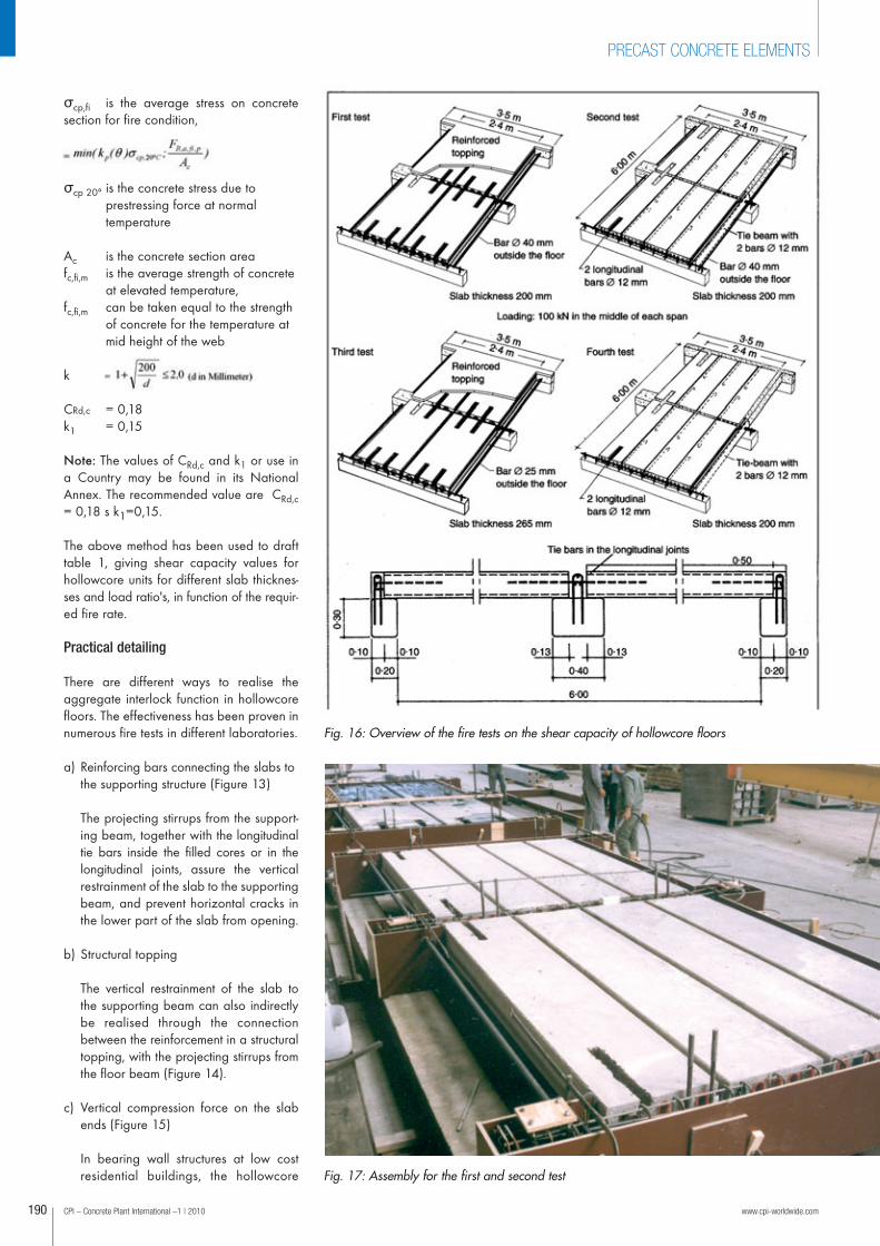
Fig. 16: Overview of the fire tests on the shear capacity of hollowcore floors
Fig. 17: Assembly for the first and second test
06a-Fertigteile_166-199_en.qxp:Layout 1 25.01.2010 11:36 Uhr Seite 190
CPI – Concrete Plant International –1 | 2010 www.cpi-worldwide.com192
PRECAST CONCRETE ELEMENTS
floors are sometimes directly supportedon the wall without further connectionreinforcement. The compression forcefrom the superposed panels may be sufficient to keep possible horizontalcracks closed and realise the aggregateinterlock mechanism. The solution is onlyapplicable for very limited shear loadingfrom self weight, imposed loading andprestres sing force.
However, the solution with projectingbars and tie beams as shown in Figure13, is preferable.
Research
In the past, more than hundred fire tests inlaboratories all over the world have beencarried out on hollowcore floor units. They
show that the flexural capacity for fireperiods of 120 minutes, and even up to180 minutes, can be obtained with normalhollowcore units, provided sufficient coverto the prestressing strands is respected.
Much less research has been carried out onthe shear capacity at fire. Experiences atlaboratory tests and real fires demonstratethat also for this aspect sufficient bearingcapacity is obtained, on condition thatgood connections with the supporting struc-ture are available. However standard firetests on hollowcore floors were seldom car-ried out with high shear loading, since thelatter is seldom governing in normal design.Three important reseach projects, carriedout in the past decades to study the shearcapacity of hollowcore floors exposed tosevere fire, are explained hereafter.
Laboratory tests in Belgium [3] [5]The research project was carried out at thefire research departments of the Universitiesof Ghent and Liege. It comprised a theore-tical study and 4 fire tests. The aim of thetheoretical study was to evaluate throughfinite element analysis, the magnitude andlocation of thermal stresses caused by differential deformation of the concrete sec-tion for different fire exposure times, butalso to examine the influence of parameterssuch as restrainment of the thermal expan-sion, catenary effect of the deflection, sizeof the cross-section and more. The calcula -tions were made with the computer pro-gram "Safir" at the University of Liège. Thecalculation results are visualised by meansof graphs. Figure 5 shows a calculationexample of the stress curves in a floor unitof 265 mm thickness, without longitudinalrestrainment of the thermal expansion.
The practical part of the project comprised4 standard fire tests of 2 h lSO fire at thelaboratory of the University of Ghent. Sincethe objective of the research was to examineexclusively the shear capacity, the test setup was designed to enable the testing of amaximum number of parameters. The testfurnace measured 6 x 3 m. The test set upof the four tests is shown on Figure 16. Eachtest comprised two floor spans of 3 m, sup-ported on three beams, and a floor width of2.40 m.
The four tests were conceived to simulatethe conditions of a real hollowcore floor,and the following parameters were includ -ed: longitudinal, transverse and peripheraltie reinforcement and a structural topping,but also the restraining effect of a surroun-ding floor structure and the edge beamsand columns.
The influence of the surrounding structurewas simulated by a longitudinal bar at bothsides of the floor, and a T -shaped ending ofthe transversal tie beams above the threesupporting beams. The size of the longitudi-
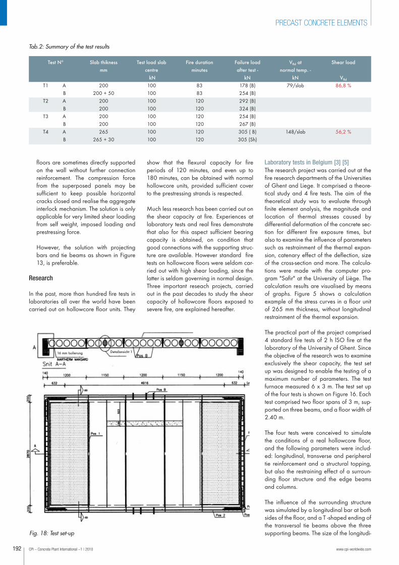
Tab.2: Summary of the test results
Test N°
T1 AB
T2 AB
T3 AB
T4 AB
Slab thikness
mm
200200 + 50
200200200200265
265 + 30
Test load slab
centre
kN
100100100100100100100100
Fire duration
minutes
8383120120120120120120
Failure load
after test -
kN
178 (B)254 (B)292 (B)324 (B)254 (B)267 (B)305 ( B)305 (Sh)
VRd at
normal temp. -
kN
79/slab
148/slab
Shear load
VRd
86,8 %
56,2 %
Fig. 18: Test set-up
Detail ansicht 116 mm Isolierung
06a-Fertigteile_166-199_en.qxp:Layout 1 25.01.2010 11:36 Uhr Seite 192
nal bars was chosen to simulate partly the longitudinal tensile capa-city of the tendons in one floor unit.
In the first and the fourth tests, a structural topping screed was caston one of the two floor spans. In the first test, the restraining effectof the topping was clearly demonstrated by a longitudinal crackappearing at mid-depth of the lateral floor face. This was due to thelarge temperature difference between the hot underside of the floorand the cool upper side. The resulting differential expansion washindered by the transversal reinforcement in the topping screed, andcaused a small longitudinal crack at mid-depth of the floor.However, it appeared that the crack was limited to the first longitudinal void and did not affect the stability of the floor. The firsttest was interrupted after 83 min because of the appearance of ahole in the slab right under the pressure vessel.
The local failure was probably caused by a concentrated contactpressure under the vessel. All other tests were stopped after 120minutes fire exposure. Immediately at the end of each test, the load-ing was increased for each floor span until failure, to check theremaining capacity after the fire. The results are given in Table 2.The failure load for the floor span with topping in the first test was254 kN. The units failed in bending, which leads to the conclusionthat the shear capacity was higher. The other floor span without topping, where a large hole was observ ed during the test, failed at a load of 178 kN, also in bending. Also in this case it can be concluded that the shear capa-city was not reached. The following three tests were stopped at 120min fire exposure. During the subsequent loading to failure, all floor
www.cpi-worldwide.com CPI – Concrete Plant International –1 | 2010 193
PRECAST CONCRETE ELEMENTS
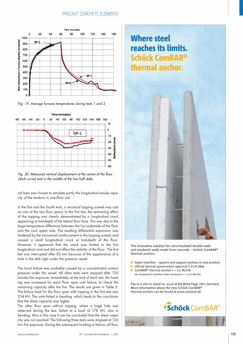
Fig. 19: Average furnace temperatures during tests 1 and 2
Fig. 20: Measured vertical displacement at the centre of the floor(dark curve) and in the middle of the two half slabs
The innovative solution for core-insulated double walls and sandwich walls made from concrete - Schöck ComBAR® thermal anchors
— faster insertion – spacers and support anchors in one product— official German government approval Z-21.8-1894— ComBAR® thermal anchor = 0.5 W/mK (as compared to stainless steel connectors: = 15.0 W/mK)
Pay us a visit on stand no. 21,22 at the BetonTage, Ulm, GermanyMore information about the new Schöck ComBAR® thermal anchors can be found at www.schoeck.de
Where steel reaches its limits. Schöck ComBAR® thermal anchor.
Anz_Thermoanker_BWI_en_87x260_rz.indd 1 14.01.2010 8:29:25 Uhr
06a-Fertigteile_166-199_en.qxp:Layout 1 25.01.2010 11:36 Uhr Seite 193
CPI – Concrete Plant International –1 | 2010 www.cpi-worldwide.com194
PRECAST CONCRETE ELEMENTS
slabs failed in bending, except one span,showing a shear failure. The underside ofthe latter floor was more damaged by spalling than the others, which mightexplain the shear failure. All failure loadswere very high in comparison to the testload of 100 kN, which has to be conside-red as a normal fire loading. The tests provethat hollowcore units dispose of a largebearing capacity at fire, both for bendingand shear.
Laboratory tests in Denmark [7]In April 2005, the Danish Precast ConcreteAssociation carried out a series of tests onthe fire resistance of hollowcore floors withhigh imposed shear loading. The purposeof the tests was to demonstrate that hollowcore slabs exposed to a 60 minutes stan-dard fire plus the subsequent cooling phasecan resist a shear loading corresponding to65 % of the ultimate shear capacity atambiant temperature.Figure 18 shows the test set-up. It comprisesa complete floor slab, composed of 5 hollowcore units of 265 mm thickness and
2.93 m span, supported on two beams andtied together by a peripheral ring beam.The idea was to simulate a real floor slabwith normal connections to the supportingstructure. The 6.18 m wide test floor wassymmetrically positioned on the test furnacewhich was 2.35 m wide. Two cantileveringzones of each 1.775 m at both sides of thefurnace were ment to simulate the restrain -ing effect of a surrounding floor to the ther-mal expansion of the fire exposed floor. Inorder to allow vertical deflection of theexposed slabs, the test zone was separatedfrom the buffer zones by cutting the twoslabs at the longitudinal edges of the furnaceover their full length. The joint was filledwith insulating material. The exposed zonecomprised hence one whole slab and twohalf slabs. The applied load was achieved with fivehydraulic jacks positioned at a distance of0.66 m from the floor support (2.5 times theslab thickness). Three tests were performedwith load levels corresponding to 65%,75% and 80% of the ultimate shear capa-city at ambient temperature.
The heating regime followed the standardtime temperature curve during 60 minutes,followed by a 90 minute cooling phaseunder full loading.The temperature registra-tions for tests 1 and 2 are shown on Figure19. After 60 minutes, the furnace was switched off and the test continued for afurther 60-90 minutes cooling phase withthe load still being appplied.
The two first tests, with shear loading of65% and 75%, supported the full appliedload for the duration of the fire and thecomplete cooling period. During the thirdtest with a loading of 80%, shear failureoccurred after 45 minutes fire exposure.There was no significant spalling in any ofthe tests. Figure 20 shows the deflection of the hollowcore units in the first test. The lowerdark curve corresponds to the deflection ofthe slab in the middle of the test zone. Theother two red curves show the deflections inthe middle of the two half slabs.
The results from the three tests prove that thehollowcore slabs were able to resist a shearload at 60 minutes standard fire exposureof 75% of the shear capacity at ambienttemperature. The slabs continued to carrythe load during a subsequent coolingperiod of 60 – 90 minutes.
Full-scale tests in UK [8]Prestressed hollowcore floors are verypopular in the UK construction market forapartment buildings with steel frame struc-ture. It is current practice to sit units directlyonto the steel frame without any tying between the units and frame for low risebuildings (under 4 storeys)However, some concern has been raisedabout the actual performance of hollowcorefloors in fire following some examples ofpremature failure due to shear in standardsmall-scale fire resistance tests. The failures
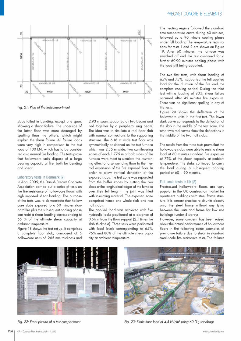
Fig. 21: Plan of the testcompartment
Fig. 22: Front picture of a test compartment Fig. 23: Static floor load of 4,5 kN/m² using 60 (1t) sandbags
06a-Fertigteile_166-199_en.qxp:Layout 1 25.01.2010 11:36 Uhr Seite 194
during the tests were attributed to the lack of connection detailingbetween the floors and the supporting structure used in practicaldesign. The purpose of the study was to investigate whether the inherentrestraint to thermal expansion, created by grouting the units toge therand around the columns, is sufficient to alleviate shear failure. Twofull-scale fire tests were carried out by the Building ResearchEstablishment at its laboratory in Middlesborough on hollowcorefloors supported on steelwork
The two fire tests were designed within a fire compartment of inter-nal plan dimensions 7.02 x 17.76 m, with an internal floor to soffitheigth of 3.6 m (Figure 21). The units were supported on steelbeams with the floor plate area 7.0 x 17.86 m. The compartmentwas formed using 100 mm thick blockwork, which was protectedwith 15 mm thick fire board, with unprotected hollowcore slabs forming the ceiling. Three ventilation openings were provided on thefront face of each compartment, each 2.2 m wide x 1.6 m high(Figure 22 ). The supporting steel work was protected using 15 mmthick fire board. A total of 15 hollowcore units were used, 1200 mmby 200 mm deep.
The two tests were identical except for the end restrainment condi -tions to the hollowcore slabs. In the first test the slab units sat direct-ly onto the supporting beams with the units notched around thecolumns. The joints between the units, and the gaps around thecolumns and the units, were filled with grout. In the second test, 2T12 bars per unit were placed in the cores and around a 19 mmshear stud fixed to the steel beam. The cores housing the rebars, theend of the slab, the gap between the units and the gap between theunits and steel columns were filled with grout. The applied load of 4.5 kN/m² was achieved using 60 sandbags(each weighing 1 t) evenly positioned over the floor plate, as shownin Figure 23 . This gave an applied load of 4.71 kN/m². The self-weight of the units was 2.96 kN/m², creating a total load of 7.67 kN/m², and an applied moment at the time of the fire of 56.37 kNm per with of unit. This gave a load ratio of 0.34 for bending and 0.26 for shear capacity.
The natural fire was designed according to the British Standard BSEN 1991-1-2. Assuming the design for an office, the fire load den-sity was 570 MJ/m² (80% fractile) . The fire load was achievedusing 40 standard (1m x 1m x 0.5m high) wooden cribs, compris -ing 50mm x 50 mm x 1000 mm wooden battens, positioned evenlyaround the compartment. The fire load was 33.25 kg of wood/m².The aim of the test was to try to follow the standard fire curve up to60 minutes to investigate the structural behaviour and to enable the
www.cpi-worldwide.com CPI – Concrete Plant International –1 | 2010
PRECAST CONCRETE ELEMENTS
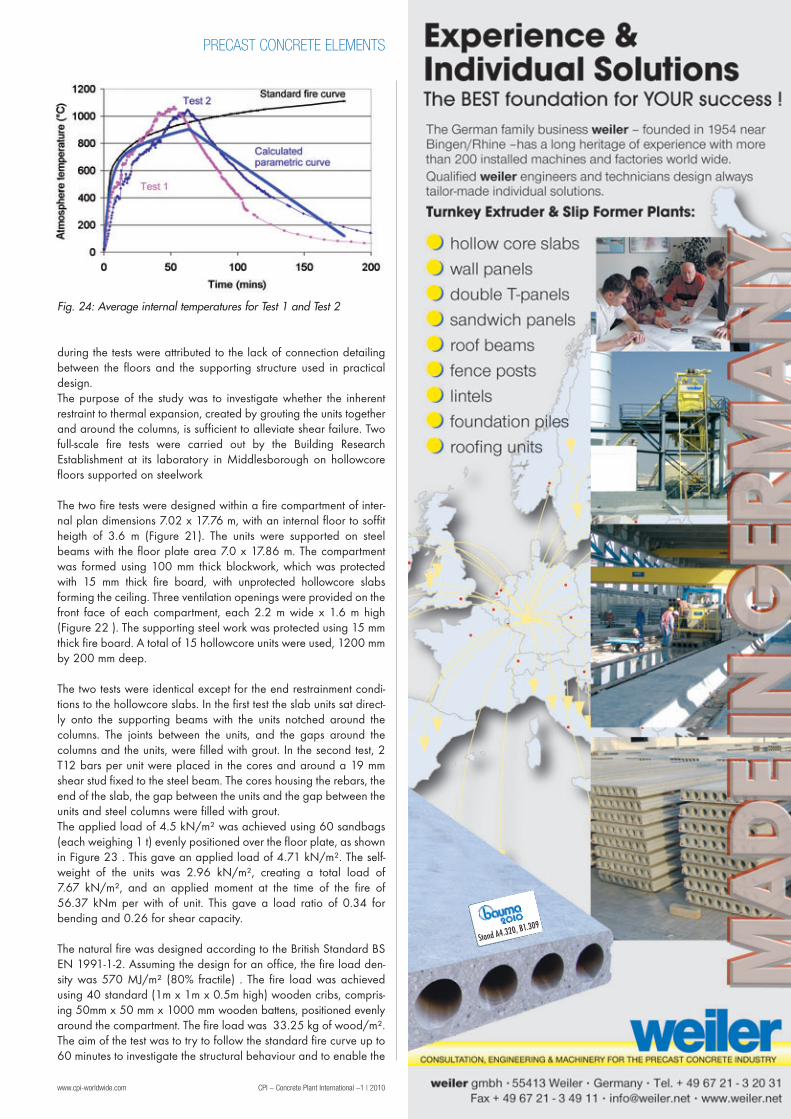
Fig. 24: Average internal temperatures for Test 1 and Test 2
Stand A4.320, B1.309
06a-Fertigteile_166-199_en.qxp:Layout 1 25.01.2010 11:36 Uhr Seite 195
CPI – Concrete Plant International –1 | 2010 www.cpi-worldwide.com196
PRECAST CONCRETE ELEMENTS
test to be compared against the structural performance in small-scale standard fire tests. Figure 24 shows the comparison betweenthe average atmosphere temperature for Test 1 and Test 2, togetherwith the calculated parametric and standard fire curve. It can beseen that the maximum average atmosphere temperature was simi-lar in both tests (1069 °C in Test 1 and 1047 °C in Test 2).
All hollowcore unts performed very well during the heating phaseof the fire, which was more severe than the standard fire curve. Thefloor, as a whole, performed also well during the cooling phase ofthe fire. The different end conditions did not affect the measured vertical dis-placement. In addition the columns in both tests were pushed outfurther than the units suggesting that there was nominal longitudinalthermal restraint to the units.
There was evidence of lateral compressive strip forming at the endsof the units caused by restraint to thermal expansion. This stripwould have enhanced the flexural capacity of the units since itwould have restraint the ends of the strands allowing some catenaryaction to occur. In addition the compressive strip could enhance theshear capacity of the units by reducing the strand slippage. Furtherwork is underway to investigate this beneficial behaviour to enableit to be utilised in practical design.
The hollowcore floor performed very well supporting the fullapplied static load for the duration of the tests. There was no significant spalling in any of the tests. The tests showed that thesmall-scale standard fire tests, used to assess fire resistance periods,can be very unrealistic and ignores the beneficial effects of wholebuild ing behaviour. The test results reinforce the experience gainedfrom real fires that hollow core floor slabs have good overall inher-ent fire resistance.
�
Literature
[1] EN 1992-1-2: Eurocode 2: Design of concrete structures – Part 1-2: General rules –Structural fire design (December 2004)
[2] CEB Bulletin N° 208 - Fire design of concrete structures Comité Euro-International duBéton, July 1991
[3] Shear resistance of prestressed hollow core floorsexposed to fire - Arnold Van Acker – Journal of the fib - Structural Concrete, 2003 . 4 .N°2
[4] Elliott, K.S., Davies G., and Omar, W., Experimental and theoretical investigation of pre-cast concrete hollow-cored slabs used as horizontal floor diaphragms. Structural Engineer,1992, 70 N° 10.
[5] Recherche SSTC: Normalisation, programme d'appui à la normalisation nationale etEuropéenne en sécurité d'incendie. Eléments préfabriqués en béton précontraint, dallesalvéolées.
[6] Fellinger, Shear and anchorage behaviour of fireexposed hollow core slabs. ISBN 90-407-2482-2
[7] Danish Prefab Concrete Association: Hollowcore slabs and fire – Documentation on shearcapacity; Birch & Krogboe A/S 17681-BEF-272850-1.doc
[8] C.G. Bailey en T. Lennon: Full-scale fire tests on hollowcore floors; The StructuralEngineer, 18 March 2008
Stand C1.307
06a-Fertigteile_166-199_en.qxp:Layout 1 26.01.2010 9:17 Uhr Seite 196


![PRODUCT GUIDE · industry, providing Precast and Prestressed products. HOLLOW CORE The Quinn hollowcore flooring system provides a fast and economic approach to building. T-]OISTS](https://img.pdfslide.us/doc/110x75/5f28c76906ba2d5ba86898d9/product-guide-industry-providing-precast-and-prestressed-products-hollow-core.jpg)