Embed Size (px)
Citation preview
HAZARD IDENTIFICATION (HAZID) STUDIES TERMS OF REFERENCE
Rev 0
01 June 2019
Vista Oil & Gas Hazard Identification (HAZID) Studies Terms of Reference (TOR) 01 June 2019
Page 1
Document Revision Status
Revision Description Author Review Approval Date
A Draft for internal review
0 Draft for client review
Vista Oil & Gas Hazard Identification (HAZID) Studies Terms of Reference (TOR) 01 June 2019
Page 2
Table of Contents 1 INTRODUCTION ......................................................................................................................................... 3
2 SCOPE ........................................................................................................................................................ 3
3 OBJECTIVES .............................................................................................................................................. 3
4 KEY EXPECTATIONS ................................................................................................................................ 3
5 TIMING ........................................................................................................................................................ 4
6 METHODOLOGY ........................................................................................................................................ 5
6.1 Steps to Conducting a HAZID ..................................................................................................................... 5
6.2 Groundwork ................................................................................................................................................. 7
6.2.1 Team ....................................................................................................................................................... 7
6.2.2 Location ................................................................................................................................................... 8
6.2.3 Supporting Documentation and Information ........................................................................................... 8
6.3 Preparation and Terms of Reference (TOR) ............................................................................................... 9
6.4 Workshop Session(s) ................................................................................................................................ 10
6.5 Preliminary Risk Assessment .................................................................................................................... 11
6.6 Recording and Reporting .......................................................................................................................... 12
7 REFERENCES .......................................................................................................................................... 12
APPENDIX 1- HAZID GUIDEWORDS ..................................................................................................................... 13
APPENDIX 2 - HAZID GUIDEWORDS (MULTIPLE SOURCES) ........................................................................... 16
APPENDIX 3 - SAMPLE HAZARD AND RISK REGISTER .................................................................................... 25
APPENDIX 4 - HAZID TABLE OF CONTENTS (TOR) ........................................................................................... 26
APPENDIX 5 - HAZID REPORT TABLE OF CONTENTS (TOR) ........................................................................... 27
APPENDIX 6 - HAZID WORKSHOP RECORD SHEET LAYOUT .......................................................................... 28
APPENDIX 7 - HAZID RISK RANKING MATRIX .................................................................................................... 29
Vista Oil & Gas Hazard Identification (HAZID) Studies Terms of Reference (TOR) 01 June 2019
Page 3
1 INTRODUCTION Hazard Identification (HAZID) is a brainstorming workshop with a multi-disciplinary team to identify potential hazards. HAZID studies may be broad in their scope and thus have a wide applicability. HAZID typically examines all reasonably possible sources of hazard during project design, construction, installation, and decommissioning activities, and for proposed changes to existing operations.
The HAZID is one technique within a suite of hazard evaluation and risk management tools. This process is at a higher level compared to a HAZOP, What-If or bowtie study. HAZID can be conducted at a unit or system level with little documentation other than a design concept.
HAZOP and What-if studies focus on a system or node level and are dependent on accurate process safety information. Bowtie studies are a detailed pictorial representation and assessment of a top event, the threats and consequences related to its materialization, and the preventive and mitigation barriers in place to manage risk.
2 SCOPE This document provides requirements for the planning, conduct, and documentation of HAZID studies.
3 OBJECTIVES The objectives of HAZIDs are to:
• Identify potential hazards,
• Determine potential consequences of the hazards,
• Identify safeguards that are in place to provide hazard prevention, control or mitigation (including planned safeguards depending on the stage of the project),
• Propose recommendations, as needed, to eliminate, prevent, control, or mitigate hazards,
• Provide early safety and risk input into design and safety management requirements for an activity, and
• Provide a clear basis for major accident event screening as part of subsequent formal safety assessment studies.
All specific objectives of the HAZID should be included in the HAZID Terms of Reference (see section 6.3).
4 KEY EXPECTATIONS Key expectations concerning HAZIDs are:
• Workshops are attended by key stakeholders including representation from design and operations,
• Workshops involve a structured process to address all hazards and potential accident events at high level,
• Adequate time given to the workshop (typically 1-3 days depending upon facility or operations complexity),
• There is early focus on risk reduction measures, in particular, inherent safety aspects and major accident event prevention,
• A HAZID report is prepared detailing the method, attendees, main conclusions and detailed workshop record sheets,
Vista Oil & Gas Hazard Identification (HAZID) Studies Terms of Reference (TOR) 01 June 2019
Page 4
• The HAZID provides the basis for a hazard / risk register (See example in Appendix 3 - Sample Hazard and Risk Register
• The HAZID provides early insight into major hazards and associated accident events and identifies, at a high level, safety critical aspects (equipment, procedures and tasks/activities) that prevent or mitigate these events, and
• Where the HAZID forms the basis for subsequent detailed formal safety assessment (FSA), potential major hazards should be clearly identified. Upon the conclusion of the FSA, it should be possible to trace each assessed hazard back through the FSA process and studies to their basis in the HAZID.
5 TIMING HAZID studies are typically conducted:
• During the appraise stage or early select stage of a project as part of the selection process for conceptual design
The time to perform a HAZID may be when the design options have progressed to the point at which selection of the preferred option is about to take place. By necessity, the level of detail is limited, focusing on major hazards. The project may also prefer to conduct a HAZID earlier, particularly if there are new technologies or hazards involved in the development.
A HAZID study may be conducted during the late select stage or early define stage of a project, when conceptual design layouts are nearing completion.
• To focus future hazard management activities in design development (for example, early front end engineering design)
A study at this stage has enough detail to be of particular value and is being done sufficiently early for its findings to interact with the FEED process. The time for starting this study may be the development of layout drawings to the point where the location of major equipment and occupied buildings has been specified. Plant layout and Process Flow Diagrams (PFD) describe the plant operating envelopes. The output from this study would provide key inputs to the systematic safety assessment of major hazards associated with the detailed design of the new site.
• For existing facilities, a HAZID may be conducted during operations to:
a. Update hazard and risk register as part of a periodic review.
b. Cover a broad range of safety hazards that may not be addressed by other hazard analysis techniques
c. Aid in populating a hazard and risk register
d. Identify hazards associated with a proposed change as part of the management of change process
e. Identify, either during a project development or existing asset operations, the potential hazards associated with operations or activities
This could include activities, such as construction, maintenance campaigns, simultaneous operations, heavy lifts, or equipment transportation activities.
This study would be most beneficial if conducted when the organizational and equipment systems involved are first specified, and a preliminary program of work has been prepared.
Vista Oil & Gas Hazard Identification (HAZID) Studies Terms of Reference (TOR) 01 June 2019
Page 5
6 METHODOLOGY
6.1 Steps to Conducting a HAZID
Conducting a HAZID involves the following key elements:
• Groundwork: Gather all relevant information about the project, drawings, decisions the HAZID is to support, client standards and expectations.
• Preparation and Terms of Reference (TOR): Prepare a document that contains HAZID objectives, scope, proposed nodes, methodology, and workshop venue etc.
• Workshop Sessions: Perform workshop per client-approved TOR and record session worksheets
• Reporting: Prepare a HAZID report document based upon the TOR and the workshop session recordings highlighting key findings.
The HAZID workshop methodology is illustrated in Figure 6.1 below.

Vista Oil & Gas Hazard Identification (HAZID) Studies Terms of Reference (TOR) 01 June 2019
Page 6
Figure 6.1: HAZID Methodology
Vista Oil & Gas Hazard Identification (HAZID) Studies Terms of Reference (TOR) 01 June 2019
Page 7
6.2 Groundwork
6.2.1 Team
HAZID Study Leader
Each HAZID study shall have a leader (also referred to as facilitator or chairman) who is acceptable to Vista Oil & Gas (“the Company”).
The HAZID leader should have the following skills and experience:
• Attended a HAZID leadership-training course that provides instruction on preparing, leading, and documenting a HAZID, as well as on the HAZID technique itself
• Participated as a HAZID team member on previous HAZIDs or acted as scribe for HAZID sessions under the leadership of a competent HAZID leader
• Has experience in the type of facility, equipment, operation, or process being reviewed
• Strong facilitation and communication skills to stimulate brainstorming, manage conflict, summarize the discussion, and guide the team to consensus on the allotted schedule
The leader is responsible for ensuring that the HAZID study report is issued.
HAZID Study Scribe
A separate person should be utilized as a dedicated scribe to record the workshop discussions. If a dedicated scribe is not chosen, it is recommended that this function not be performed by the study leader, who should concentrate on effectively and expeditiously leading the study.
To ensure that the leader and team are not distracted by providing direction to the scribe, a scribe should:
• Be familiar with the design of the type of process or facility that will be analysed
• Have good skills in listening and scribing
• Be a technical consultant rather than a non-technical administrator
The scribe should also:
• Prepare the TOR under the direction of the leader
• Work with the leader to ensure that study documentation is complete and recommendations are clearly worded
• Prepare the HAZID report for approval and issue by the leader
HAZID Study Team
The quality of the HAZID study is dependent upon the knowledge and the experience of team members involved. Therefore, selection of team members is critical for successful HAZID study. Specifically:
• The HAZID study shall be conducted with input from a multidisciplinary team familiar with the project or facility
• The TOR for the HAZID study shall identify the team members and contact information
• To keep meetings manageable, attendees should be kept to a minimum without compromising the HAZID quality. The suggested minimum number of participants should be three people (excluding the facilitator and
Vista Oil & Gas Hazard Identification (HAZID) Studies Terms of Reference (TOR) 01 June 2019
Page 8
scribe), and the suggested maximum number of participants should be approximately 12 people. Exceptions to the recommended number of participants can occur if, for example, multiple entities are involved in a single operation and their representation is required from a wider understanding and planning perspective
• Substitution of HAZID study team members should be avoided or minimized to ensure continuity and homogeneity of the study
• The HAZID leader should work with the client to select and appoint competent team members based on their experience and the type and scale of the study being conducted
• Team membership may include engineering and operating expertise with an understanding of and experience with process/facility design, design intent, equipment to be used, and operations at the site
Depending on the scope of the HAZID study, attendance may be limited to those system interfaces or specialist knowledge areas for which participants are involved. All planned participants should be present at the kick-off of the HAZID study to ensure a common understanding of the HAZID methodology and scope.
6.2.2 Location
The study location should be selected and prepared in advance with documentation, computer aids for recording, projection screens, communication, posters, 3D-models if available, and others. The location should be large enough to comfortably accommodate the participants with a minimum of external disturbance. Ideally the venue should have easy access to refreshment facilities to allow regular short breaks with minimal disruption. A data projector must be available that will allow all participants to review information recorded by the scribe.
6.2.3 Supporting Documentation and Information
Documentation and information required for the HAZID study should be identified in the TOR and should be prepared prior to the workshop.
HAZID documentation and information varies, depending on the study scope and timing, and must be provided to the HAZID facilitator, at least a week prior to the workshop meetings. This enables effective preparation for the workshop. The required documentation may include:
• Facility layout, including location of major equipment and occupied buildings
• Location and nature of the terrain and environmental conditions
• Principal operations and other activities
• Details of hazardous inventories
• Chemical and materials/equipment handling
• Process type/design and utility data, such as process flow diagrams (PFD), piping and instrumentation diagrams (P&IDs), and operating envelopes
• Design philosophies, including manning, operating, maintenance, and safety
• Findings of any prior HAZID studies
• Accident history for similar units
• Emergency response plans
Vista Oil & Gas Hazard Identification (HAZID) Studies Terms of Reference (TOR) 01 June 2019
Page 9
• Plans for construction, transportation, and installation activities
• Hazard and risk register
• Description of neighbouring facilities, operations, and areas of occupancy.
6.3 Preparation and Terms of Reference (TOR)
A TOR should be developed for each study and agreed with all stakeholders. The TOR should be issued at least one week prior to the workshop and should include:
• Objective
• Scope including:
1. Facility and/or process boundaries of the review including whether potential hazards from neighbouring plants or facilities will be included
2. Types of hazards to be considered, e.g.,
• Health and safety
• Environment
• Privilege to operate
• Asset damage and business interruption
3. Operational modes to be considered, e.g.,
• Routine operations
• Turnaround or shutdown
• Fabrication, transportation, installation/construction
• Simultaneous operations (SIMOPS)
• Overall methodology and whether risk ranking will be used.
If the preferred method is to use risk ranking, then the Company’s risk matrix must be used. In absence of the company provided risk matrix, the HAZID consultant will use the standard risk matrix presented in Appendix 7 - HAZID Risk Ranking Matrix for a further discussion on risk assessment.
• The breakdown of the HAZID session(s) into logical ‘nodes’
The HAZID study leader should organise the study into ‘nodes’ (also termed as systems, activities, or review areas) to ensure inclusion of the full study scope in a logical and structured manner.
There are no firm rules regarding this organisation. However, it should be logical and clear such that all participants understand the area in which the study attention is currently focused. In producing and processing facilities, ‘nodes’ may be selected based on “following the molecule” through the production train from wells to export. For installation operations, systems are selected based on major steps in the installation operations representing the progression of the installation campaign.
Nodes may be organised by:
• Specific process units in an existing operation or the transportation phases of a project
Vista Oil & Gas Hazard Identification (HAZID) Studies Terms of Reference (TOR) 01 June 2019
Page 10
• Sections of an operation or design, such as the distillation section of a process or the loading at a service station or the hull of an offshore facility
• Individual pieces of equipment and piping as in a HAZOP
• Steps of an operation or activity
• Proposed standard worksheet and defined field hierarchy.
• Guidewords that could assist in the workshop brainstorming session(s)
Guidewords should be consistent with the sector, industry or facility type expected hazards and major accident events [e.g. refer to Appendix 1- HAZID Guidewords & Appendix 2 - HAZID Guidewords (Multiple Sources)]
• Personnel that are required to attend the workshop
• Schedule and deliverables
The workshop should be broken down in specific sessions based on the scope. The HAZID sessions should not last more than eight hours per day in order to maintain the quality of the HAZID study and avoid team fatigue.
• Reference documents (e.g., site layout, process type)
• Documentation of items not directly related to hazard identification process by using a separate log (e.g. Parking Lot)
Client comments or customizations (e.g., HAZID worksheet, risk assessment matrix) to the TOR need to be timely incorporated before the workshop sessions.
A sample table of contents for the TOR is given in Appendix 4 - HAZID Table of Contents (TOR).
6.4 Workshop Session(s)
At the start of the workshop, the leader should provide an orientation to the team to ensure that everybody is at the same point of knowledge with respect to the study, including:
• Introductions of participants
• Review of study TOR, including study objectives, scope and methodology
• Ground rules for the study and expectations of team members
• An overall review of the facilities, operations and/or activities. It is good practice to request in advance that the Client arrange a (short) overview of the facility, activity etc that is the subject of the HAZID. This may be achieved using a model, plot plans, or a plant walkthrough. If site exists or is at a sufficient stage of construction, a site visit would be advisable.
For each ‘node’:
• Where appropriate, a knowledgeable team member should give an overview of the specific ‘nodes’ facilities, operations or activities.
• Potential hazards should be identified, using the guidewords to assist in the identification.
• Potential unmitigated consequences resulting from identified hazards should be considered.
Vista Oil & Gas Hazard Identification (HAZID) Studies Terms of Reference (TOR) 01 June 2019
Page 11
• Hazards and consequences may be ranked for risk to facilitate future work process and decision-making
• Any existing safeguards (barriers and recovery measures, planned safeguards for projects in Select or pre-FEED stage) should be documented.
• It is considered best practice to document hazard-scenario pairs horizontally, recording safeguards/barriers separately (i.e. one per line); and capturing in the worksheets capture tag numbers, grid locations, document references, and any other applicable information.
• Recommendations to eliminate, prevent, control, or mitigate hazard should be generated. The HAZID leader should ensure that:
• There is team consensus on recommendations
• Recommendations are clear and complete. All recommendations should be standalone (e.g., understandable without the benefit of the worksheets). Any well written recommendation contains the three W’s:
• What,
• Where, and
• Why
For example, “add a relief valve (WHAT?) downstream of positive displacement pump P-101 (WHERE?) to prevent casing overpressure in the event of accidental shut-in (WHY?)”
Often, the team may recognise that further analysis is needed for a particular issue which is beyond the scope of the HAZID study, such as fire hazard analysis, explosion hazard analysis, root cause analysis, engineering calculations, or simply further research and gathering of information. These issues should be captured as recommendations. Ultimately, the design and operating team take responsibility for the system, so it is this team that should propose the most appropriate response.
The proposed recommendations must be written in such a manner that they can be closed at the appropriate time and not remain open ended throughout the entire lifecycle of the project. It is a good practice to reserve the last hour of the workshop to review issued recommendations. The Scribe or facilitator can read out loud the proposed actions to ensure the team’s consensus about the appropriateness and completeness of the recommendation, having in mind it will be understood by the assigned owner and the milestone/date for completion reasonable.
The duration of the HAZID workshop may vary in terms of the number of days, depending on the scope of a given study. But, it is important that each day of the session does not exceed 6-7 hours of meeting time, to maintain interest amongst the team members rendering an efficient and effective workshop.
6.5 Preliminary Risk Assessment
Often a HAZID will require a preliminary risk assessment to be undertaken to be able to prioritise the hazards identified. Such a risk assessment should normally be based on the inherent risk associated with the hazard, ie the risk without prevention or mitigation measures. Such a risk measure indicates the potential threat should prevention or mitigation measures become downgraded. Sometimes there is a requirement to provide an assessment of residual risk, ie the risk after prevention and mitigation measures have been taken into account. The difference between inherent and residual risk shows the importance of the measure in place to reduce risk. Typically a client will have its own risk acceptance matrix and will supply this for use in the HAZID. In the absence
Vista Oil & Gas Hazard Identification (HAZID) Studies Terms of Reference (TOR) 01 June 2019
Page 12
of a client-supplied matrix, it is recommended that that the matrix in 0 is used. This matrix is based on the matrix in ISO 17776 [1].
6.6 Recording and Reporting
The HAZID study report serves as the permanent record of the HAZID study and is used by people that were not a part of the HAZID study team. Over time, the HAZID report is the only indicator of the quality and completeness of the HAZID study and serves as a record of the team diligence. It is important that the HAZID leader has the attention to detail to ensure clarity and accuracy of the worksheets and report.
A table of contents for the report is given in Appendix 5 - HAZID Report Table of Contents (TOR).
It is recommended that a client-approved HAZID worksheet and PHA-Pro be used to record HAZID workshop sessions. Worksheets can then be exported to Word or Excel if necessary. Data should only be exported following tidy-up of the worksheets by the scribe, and approval by the leader. Also, if there are comments on the worksheets after the report has been issued, the PHA-Pro files needs to be updated accordingly for future reference.
An example record sheet layout is given in Appendix 6 - HAZID Workshop Record Sheet Layout.
The discussions of the HAZID workshop are captured by the HAZID Scribe. Care must be taken to note that the names and expertise of team members and participants should be recorded, including specialist personnel who attend for a limited time. Attendees can be classed a full or part time in the report.
Items not directly related to the hazard identification process are captured in a separate log (e.g. parking lot items) and issued as part of the HAZID report.
7 REFERENCES [1] ISO 17776-2002 Petroleum and natural gas industries – Offshore production installations – Guidelines on
tools and techniques for hazard identification and risk assessment, 2002
[2] UK HSE HSL/2005/58, Review of Hazard Identification Techniques, 2005
[3] NOPSA N-04300-GN0107 - Guidance Note - Hazard Identification, 2010
[4] CCPS, Guidelines for Hazard Evaluation Procedures, Third Edition 2008
Vista Oil & Gas Hazard Identification (HAZID) Studies Terms of Reference (TOR) 01 June 2019
Page 13
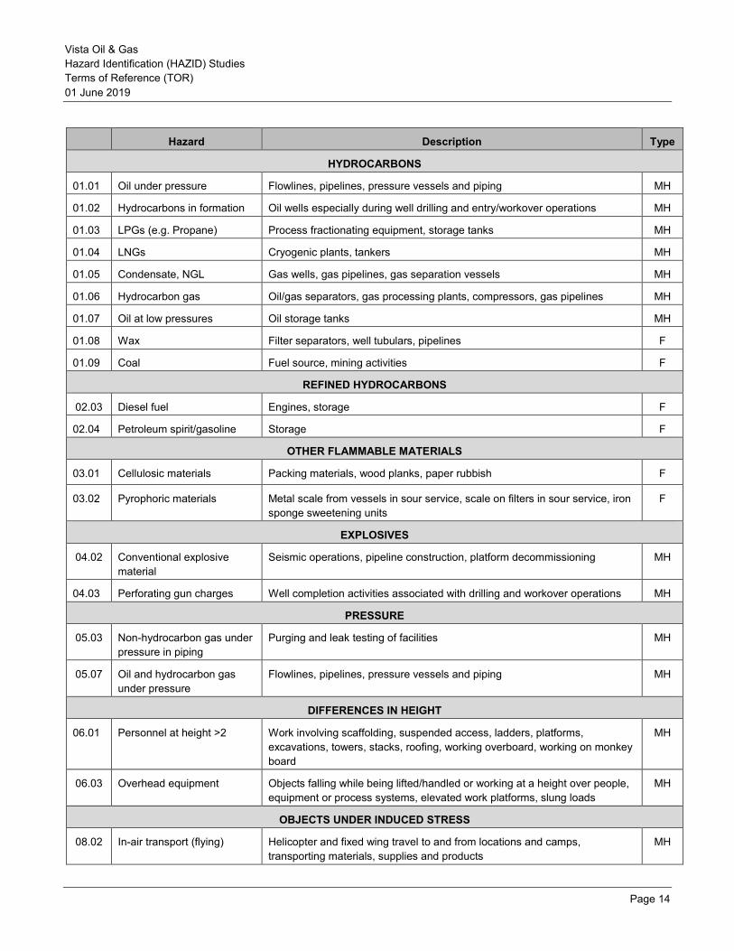
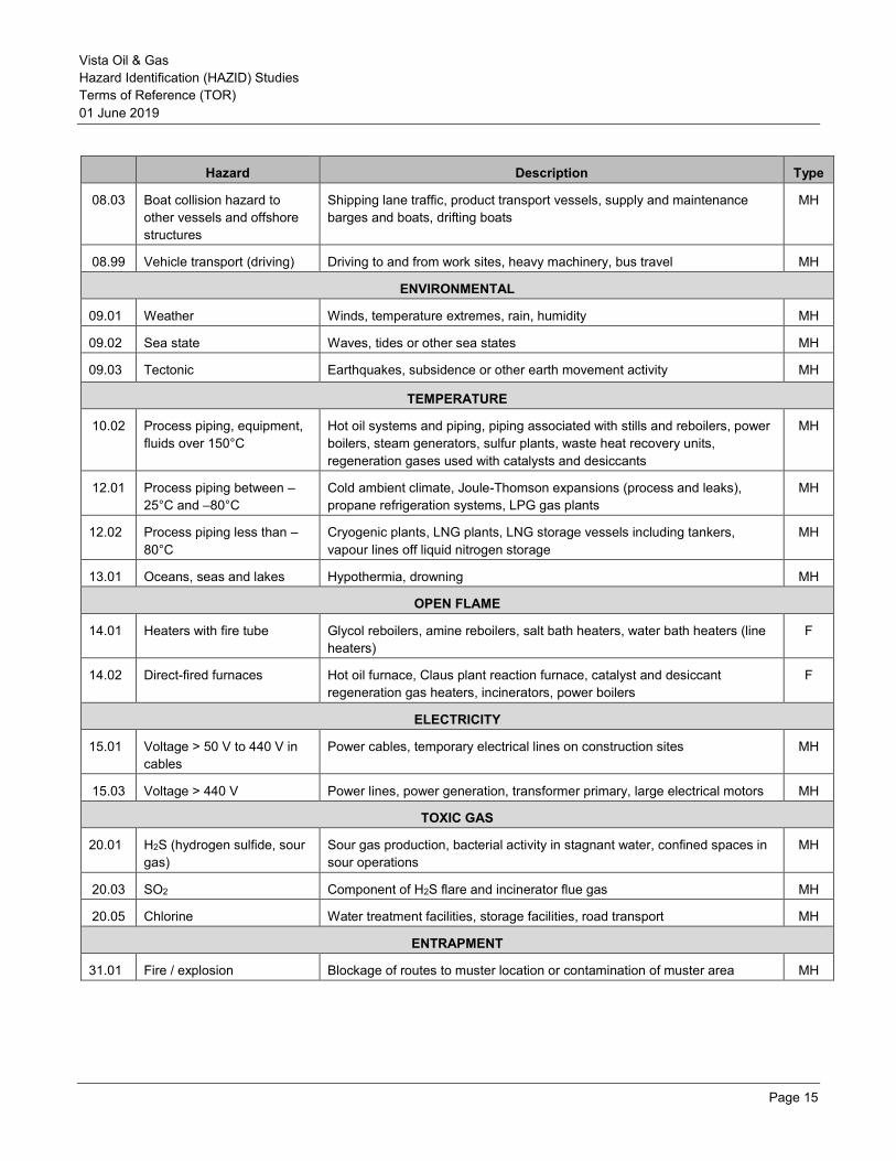
APPENDIX 1- HAZID GUIDEWORDS ISO 17776 [1] provides general guidance on tools and techniques for hazard identification and risk assessment in offshore oil & gas production facilities. This document also presents a comprehensive hazard checklist for identifying different hazards which may be associated with offshore O&G production activities. The original list in the standard covers all types of hazard, including major accident, flammable, workplace and security hazards. Since the majority of HAZID studies undertaken by ERM will be concerned with major accidents, the checklist has been edited to show only those hazards associated with major accidents or flammable hazards.
This type of checklist only provides general high level guidance on the types of hazard encountered and the workshop will need to explore the detail of, for example:
• how this hazard category is present in a particular node, • the possible harmful effects of that hazard, • what are the possible causes of any hazardous event • whether there are any known prevention or mitigation measures in place for this hazard
Vista Oil & Gas Hazard Identification (HAZID) Studies Terms of Reference (TOR) 01 June 2019
Page 14
Hazard Description Type
HYDROCARBONS
01.01 Oil under pressure Flowlines, pipelines, pressure vessels and piping MH
01.02 Hydrocarbons in formation Oil wells especially during well drilling and entry/workover operations MH
01.03 LPGs (e.g. Propane) Process fractionating equipment, storage tanks MH
01.04 LNGs Cryogenic plants, tankers MH
01.05 Condensate, NGL Gas wells, gas pipelines, gas separation vessels MH
01.06 Hydrocarbon gas Oil/gas separators, gas processing plants, compressors, gas pipelines MH
01.07 Oil at low pressures Oil storage tanks MH
01.08 Wax Filter separators, well tubulars, pipelines F
01.09 Coal Fuel source, mining activities F
REFINED HYDROCARBONS
02.03 Diesel fuel Engines, storage F
02.04 Petroleum spirit/gasoline Storage F
OTHER FLAMMABLE MATERIALS
03.01 Cellulosic materials Packing materials, wood planks, paper rubbish F
03.02 Pyrophoric materials Metal scale from vessels in sour service, scale on filters in sour service, iron sponge sweetening units
F
EXPLOSIVES
04.02 Conventional explosive material
Seismic operations, pipeline construction, platform decommissioning MH
04.03 Perforating gun charges Well completion activities associated with drilling and workover operations MH
PRESSURE
05.03 Non-hydrocarbon gas under pressure in piping
Purging and leak testing of facilities MH
05.07 Oil and hydrocarbon gas under pressure
Flowlines, pipelines, pressure vessels and piping MH
DIFFERENCES IN HEIGHT
06.01 Personnel at height >2 Work involving scaffolding, suspended access, ladders, platforms, excavations, towers, stacks, roofing, working overboard, working on monkey board
MH
06.03 Overhead equipment Objects falling while being lifted/handled or working at a height over people, equipment or process systems, elevated work platforms, slung loads
MH
OBJECTS UNDER INDUCED STRESS
08.02 In-air transport (flying) Helicopter and fixed wing travel to and from locations and camps, transporting materials, supplies and products
MH
Vista Oil & Gas Hazard Identification (HAZID) Studies Terms of Reference (TOR) 01 June 2019
Page 15
Hazard Description Type
08.03 Boat collision hazard to other vessels and offshore structures
Shipping lane traffic, product transport vessels, supply and maintenance barges and boats, drifting boats
MH
08.99 Vehicle transport (driving) Driving to and from work sites, heavy machinery, bus travel MH
ENVIRONMENTAL
09.01 Weather Winds, temperature extremes, rain, humidity MH
09.02 Sea state Waves, tides or other sea states MH
09.03 Tectonic Earthquakes, subsidence or other earth movement activity MH
TEMPERATURE
10.02 Process piping, equipment, fluids over 150°C
Hot oil systems and piping, piping associated with stills and reboilers, power boilers, steam generators, sulfur plants, waste heat recovery units, regeneration gases used with catalysts and desiccants
MH
12.01 Process piping between –25°C and –80°C
Cold ambient climate, Joule-Thomson expansions (process and leaks), propane refrigeration systems, LPG gas plants
MH
12.02 Process piping less than –80°C
Cryogenic plants, LNG plants, LNG storage vessels including tankers, vapour lines off liquid nitrogen storage
MH
13.01 Oceans, seas and lakes Hypothermia, drowning MH
OPEN FLAME
14.01 Heaters with fire tube Glycol reboilers, amine reboilers, salt bath heaters, water bath heaters (line heaters)
F
14.02 Direct-fired furnaces Hot oil furnace, Claus plant reaction furnace, catalyst and desiccant regeneration gas heaters, incinerators, power boilers
F
ELECTRICITY
15.01 Voltage > 50 V to 440 V in cables
Power cables, temporary electrical lines on construction sites MH
15.03 Voltage > 440 V Power lines, power generation, transformer primary, large electrical motors MH
TOXIC GAS
20.01 H2S (hydrogen sulfide, sour gas)
Sour gas production, bacterial activity in stagnant water, confined spaces in sour operations
MH
20.03 SO2 Component of H2S flare and incinerator flue gas MH
20.05 Chlorine Water treatment facilities, storage facilities, road transport MH
ENTRAPMENT
31.01 Fire / explosion Blockage of routes to muster location or contamination of muster area MH
Vista Oil & Gas Hazard Identification (HAZID) Studies Terms of Reference (TOR) 01 June 2019
Page 16
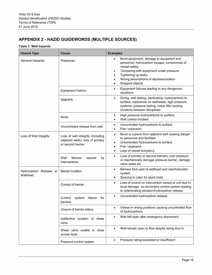
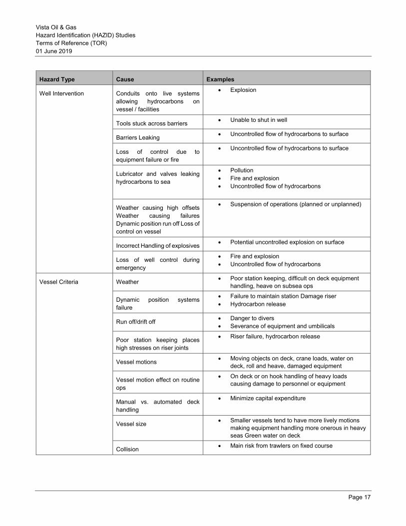
APPENDIX 2 - HAZID GUIDEWORDS (MULTIPLE SOURCES) Table 1: Well hazards
Hazard Type Cause Examples
General Hazards Pressures • Burst equipment, damage to equipment and personnel, hydrocarbon escape, compromise of vessel safety
• Tampering with equipment under pressure • Tightening up leaks • Wrong assumptions of depressurization • Dropped objects
Equipment Failure • Equipment failures leading to any dangerous situations
SIMOPS • Diving, well testing, perforating, hydrocarbons to surface, explosives on wellheads, high pressure systems, pressure testing, crane lifts causing incidents between disciplines
Kicks • High pressure hydrocarbons to surface • Well control incident
Uncontrolled release from well • Uncontrolled hydrocarbons to surface • Fire / explosion
Loss of Well Integrity Loss of well integrity (including adjacent wells), loss of primary or second barrier
• Burst or rupture from adjacent well causing danger to personnel and facilities
• Uncontrolled hydrocarbons to surface • Fire / explosion • Loss of vessel buoyancy
Well failures caused by interventions
• Loss of primary or second barriers, over pressure or mechanically damage pressure barrier, damage valve seats etc.
Hydrocarbon Release at Wellhead
Barrier location • Barriers form part of wellhead and riser/lubricator system
• Spacing to cater for stuck tools
Control of barrier • Loss of control on intervention vessel or unit due to local damage, no secondary control system leading to deteriorating situation/hydrocarbon release
Control system failure for barriers
• Uncontrolled hydrocarbon release
Unsure of barrier status • Valves in wrong positions causing uncontrolled flow of hydrocarbons
Ineffective location of shear rams
• Well left open after emergency disconnect
Shear rams unable to close across tools
• Well remain open to flow despite being shut in
Pressure control system • Pressure rating exceeded or insufficient
Vista Oil & Gas Hazard Identification (HAZID) Studies Terms of Reference (TOR) 01 June 2019
Page 17
Hazard Type Cause Examples
Well Intervention Conduits onto live systems allowing hydrocarbons on vessel / facilities
• Explosion
Tools stuck across barriers • Unable to shut in well
Barriers Leaking • Uncontrolled flow of hydrocarbons to surface
Loss of control due to equipment failure or fire
• Uncontrolled flow of hydrocarbons to surface
Lubricator and valves leaking hydrocarbons to sea
• Pollution • Fire and explosion • Uncontrolled flow of hydrocarbons
Weather causing high offsets Weather causing failures Dynamic position run off Loss of control on vessel
• Suspension of operations (planned or unplanned)
Incorrect Handling of explosives • Potential uncontrolled explosion on surface
Loss of well control during emergency
• Fire and explosion • Uncontrolled flow of hydrocarbons
Vessel Criteria Weather • Poor station keeping, difficult on deck equipment handling, heave on subsea ops
Dynamic position systems failure
• Failure to maintain station Damage riser • Hydrocarbon release
Run off/drift off • Danger to divers • Severance of equipment and umbilicals
Poor station keeping places high stresses on riser joints
• Riser failure, hydrocarbon release
Vessel motions • Moving objects on deck, crane loads, water on deck, roll and heave, damaged equipment
Vessel motion effect on routine ops
• On deck or on hook handling of heavy loads causing damage to personnel or equipment
Manual vs. automated deck handling
• Minimize capital expenditure
Vessel size • Smaller vessels tend to have more lively motions making equipment handling more onerous in heavy seas Green water on deck
Collision • Main risk from trawlers on fixed course

Vista Oil & Gas Hazard Identification (HAZID) Studies Terms of Reference (TOR) 01 June 2019
Page 18
Hazard Type Cause Examples
Facility Equipment Failure of temporary equipment • Ignition source • Electrocution • Equipment failure leading to well control issues • Health and safety of operators at risk
Temporary equipment not designed for vessel motions
• Failure to operate, swinging loads, moving equipment
Handling systems not designed for vessel motions
• Vessel motions causing equipment to move violently, damage to personnel and equipment
• Crane loads swinging
Heavy equipment handling (lubricator, well head, DH tools)
• Dangerous swinging heavy loads
Diving hazards and lack of diving focus
• Nonstandard diving activities leading to reduction in diver safety
• Escape of hydrocarbons into diving system • Effect on divers of well intervention problems
Intervention crews not accustomed to vessel motions
• Many fixed installation or semi-submersible based crews are new to operations on a lively monohull
Diving operations Dropped objects • Dropped objects on personnel, equipment or hydrocarbon lines
Fluid releases from well or vessel
• Risks of fire, contamination of diving system or support team and DSV on surface, contamination of diving system in bell subsurface
Pressure testing • Burst pipes and equipment, surface and subsurface explosions
Breaking into pressure systems • Breaking into a pressure system without being properly bled down or isolated
Isolations for divers • Breaking into a pressure system without being properly bled down or isolated
Confirmation of pressures • Wrong diagnosis of pressure within system
Being adjacent to wells (diving, marine etc.)
• Risk of diver umbilical or down lines snagging adjacent wells
Focus split between diving and Well intervention
• SIMOPS - lack of focus and awareness causing hazardous conditions
Poor access requiring long umbilicals
Diving within anchor patterns
Vessel blow on
• Trapped umbilicals or divers
Vista Oil & Gas Hazard Identification (HAZID) Studies Terms of Reference (TOR) 01 June 2019
Page 19
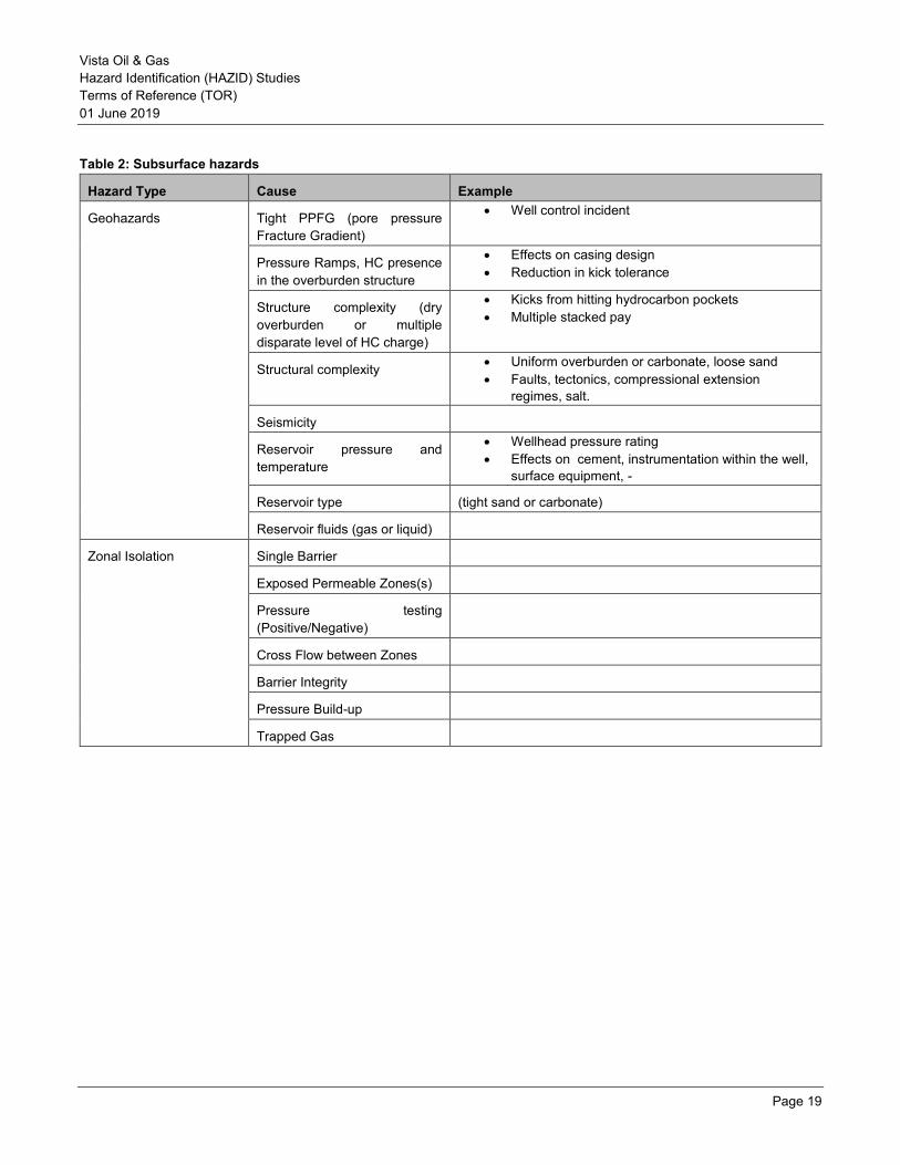
Table 2: Subsurface hazards
Hazard Type Cause Example
Geohazards
Tight PPFG (pore pressure Fracture Gradient)
• Well control incident
Pressure Ramps, HC presence in the overburden structure
• Effects on casing design • Reduction in kick tolerance
Structure complexity (dry overburden or multiple disparate level of HC charge)
• Kicks from hitting hydrocarbon pockets • Multiple stacked pay
Structural complexity • Uniform overburden or carbonate, loose sand • Faults, tectonics, compressional extension
regimes, salt.
Seismicity
Reservoir pressure and temperature
• Wellhead pressure rating • Effects on cement, instrumentation within the well,
surface equipment, -
Reservoir type (tight sand or carbonate)
Reservoir fluids (gas or liquid)
Zonal Isolation Single Barrier
Exposed Permeable Zones(s)
Pressure testing (Positive/Negative)
Cross Flow between Zones
Barrier Integrity
Pressure Build-up
Trapped Gas

Vista Oil & Gas Hazard Identification (HAZID) Studies Terms of Reference (TOR) 01 June 2019
Page 20
Table 3 represents a list of known hazardous conditions for rig activities. Use when completing the HAZID study in addition to the hazard considerations listed in GP 48-05 Annex A.
Table 3: Rig hazards
Hazard Type Cause
BOP/Riser Deployment Dropped BOP/Riser • Ignition source • Electrocution • Equipment failure leading to well control issues • Health and safety of operators at risk • Damage to equipment
Riser Failure
Installation Workover Control Systems (IWOCS) Failure
Dropped Object in Hole
ROV Clashing
Perforations Premature Firing
Unsuccessful Firing • Unable to perforate
Firing on Topsides • Health and safety of operators at risk • Damage to equipment
Equipment Integrity Coil Tubing Failure • Equipment failure leading to well control issues • Health and safety of operators at risk • Damage to equipment Wire Line Failure
Overpull
E-Line Failure
Chemicals Wrong Chemical • Health and safety of operators at risk • Pollution
Wrong Composition
Reaction of Chemical
Corrosive
Vista Oil & Gas Hazard Identification (HAZID) Studies Terms of Reference (TOR) 01 June 2019
Page 21
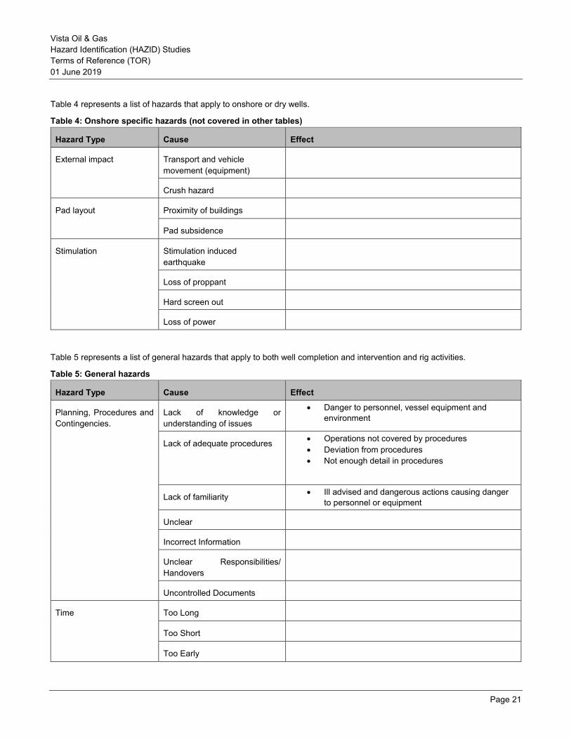
Table 4 represents a list of hazards that apply to onshore or dry wells.
Table 4: Onshore specific hazards (not covered in other tables)
Hazard Type Cause Effect
External impact Transport and vehicle movement (equipment)
Crush hazard
Pad layout Proximity of buildings
Pad subsidence
Stimulation Stimulation induced earthquake
Loss of proppant
Hard screen out
Loss of power
Table 5 represents a list of general hazards that apply to both well completion and intervention and rig activities.
Table 5: General hazards
Hazard Type Cause Effect
Planning, Procedures and Contingencies.
Lack of knowledge or understanding of issues
• Danger to personnel, vessel equipment and environment
Lack of adequate procedures • Operations not covered by procedures • Deviation from procedures • Not enough detail in procedures
Lack of familiarity • Ill advised and dangerous actions causing danger to personnel or equipment
Unclear
Incorrect Information
Unclear Responsibilities/ Handovers
Uncontrolled Documents
Time Too Long
Too Short
Too Early
Vista Oil & Gas Hazard Identification (HAZID) Studies Terms of Reference (TOR) 01 June 2019
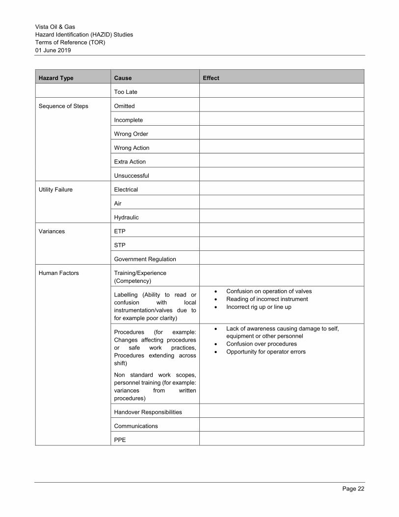
Page 22
Hazard Type Cause Effect
Too Late
Sequence of Steps Omitted
Incomplete
Wrong Order
Wrong Action
Extra Action
Unsuccessful
Utility Failure Electrical
Air
Hydraulic
Variances ETP
STP
Government Regulation
Human Factors Training/Experience (Competency)
Labelling (Ability to read or confusion with local instrumentation/valves due to for example poor clarity)
• Confusion on operation of valves • Reading of incorrect instrument • Incorrect rig up or line up
Procedures (for example: Changes affecting procedures or safe work practices, Procedures extending across shift)
Non standard work scopes, personnel training (for example: variances from written procedures)
• Lack of awareness causing damage to self, equipment or other personnel
• Confusion over procedures • Opportunity for operator errors
Handover Responsibilities
Communications
PPE
Vista Oil & Gas Hazard Identification (HAZID) Studies Terms of Reference (TOR) 01 June 2019
Page 23
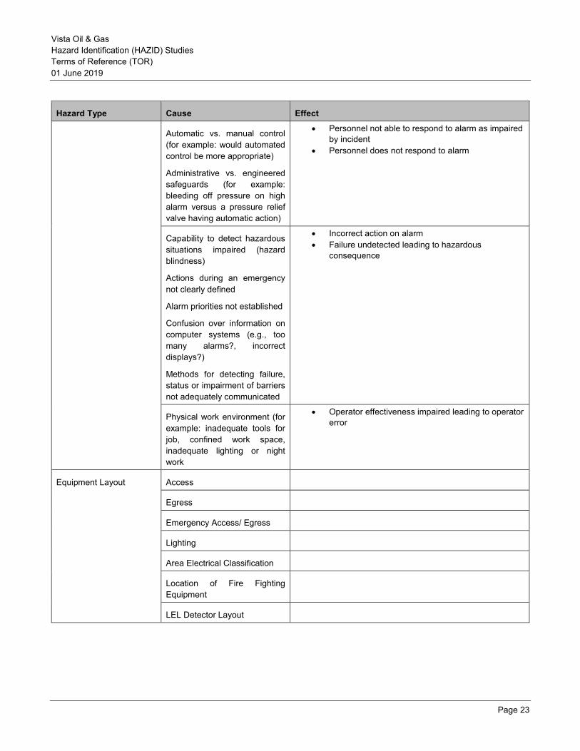
Hazard Type Cause Effect
Automatic vs. manual control (for example: would automated control be more appropriate)
Administrative vs. engineered safeguards (for example: bleeding off pressure on high alarm versus a pressure relief valve having automatic action)
• Personnel not able to respond to alarm as impaired by incident
• Personnel does not respond to alarm
Capability to detect hazardous situations impaired (hazard blindness)
Actions during an emergency not clearly defined
Alarm priorities not established
Confusion over information on computer systems (e.g., too many alarms?, incorrect displays?)
Methods for detecting failure, status or impairment of barriers not adequately communicated
• Incorrect action on alarm • Failure undetected leading to hazardous
consequence
Physical work environment (for example: inadequate tools for job, confined work space, inadequate lighting or night work
• Operator effectiveness impaired leading to operator error
Equipment Layout Access
Egress
Emergency Access/ Egress
Lighting
Area Electrical Classification
Location of Fire Fighting Equipment
LEL Detector Layout
Vista Oil & Gas Hazard Identification (HAZID) Studies Terms of Reference (TOR) 01 June 2019
Page 24
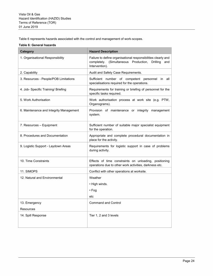
Table 6 represents hazards associated with the control and management of work-scopes.
Table 6: General hazards
Category Hazard Description
1. Organisational Responsibility Failure to define organisational responsibilities clearly and completely. (Simultaneous Production, Drilling and Intervention).
2. Capability Audit and Safety Case Requirements.
3. Resources - People/POB Limitations Sufficient number of competent personnel in all specialisations required for the operations.
4. Job- Specific Training/ Briefing Requirements for training or briefing of personnel for the specific tasks required.
5. Work Authorisation Work authorisation process at work site (e.g. PTW, Organograms).
6. Maintenance and Integrity Management Provision of maintenance or integrity management system.
7. Resources – Equipment Sufficient number of suitable major specialist equipment for the operation.
8. Procedures and Documentation Appropriate and complete procedural documentation in place for the activity.
9. Logistic Support - Laydown Areas Requirements for logistic support in case of problems during activity.
10. Time Constraints Effects of time constraints on unloading, positioning operations due to other work activities, darkness etc.
11. SIMOPS Conflict with other operations at worksite.
12. Natural and Environmental Weather
• High winds.
• Fog
etc
13. Emergency
Resources
Command and Control
14. Spill Response Tier 1, 2 and 3 levels
Vista Oil & Gas Hazard Identification (HAZID) Studies Terms of Reference (TOR) 01 June 2019
Page 25
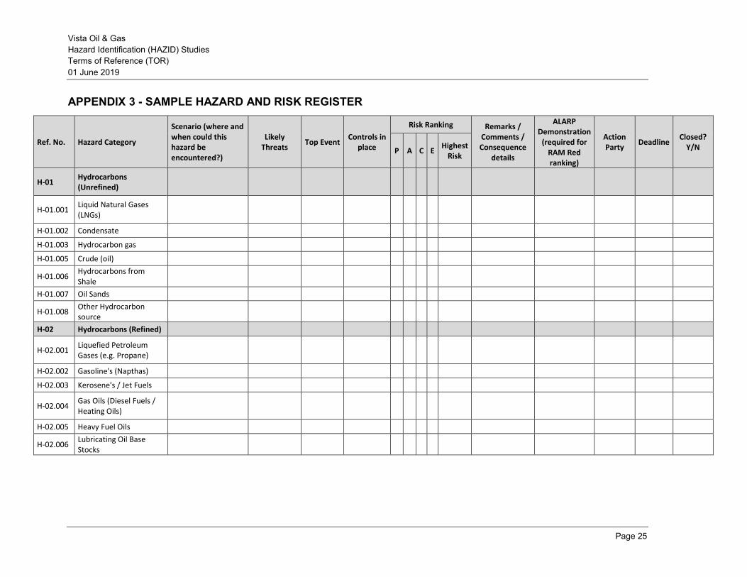
APPENDIX 3 - SAMPLE HAZARD AND RISK REGISTER
Ref. No. Hazard Category
Scenario (where and when could this hazard be encountered?)
Likely Threats
Top Event Controls in
place
Risk Ranking Remarks / Comments / Consequence
details
ALARP Demonstration
(required for RAM Red ranking)
Action Party
Deadline Closed?
Y/N P A C E Highest
Risk
H-01 Hydrocarbons (Unrefined)
H-01.001 Liquid Natural Gases (LNGs)
H-01.002 Condensate
H-01.003 Hydrocarbon gas
H-01.005 Crude (oil)
H-01.006 Hydrocarbons from Shale
H-01.007 Oil Sands
H-01.008 Other Hydrocarbon source
H-02 Hydrocarbons (Refined)
H-02.001 Liquefied Petroleum Gases (e.g. Propane)
H-02.002 Gasoline's (Napthas)
H-02.003 Kerosene's / Jet Fuels
H-02.004 Gas Oils (Diesel Fuels / Heating Oils)
H-02.005 Heavy Fuel Oils
H-02.006 Lubricating Oil Base Stocks
Vista Oil & Gas Hazard Identification (HAZID) Studies Terms of Reference (TOR) 01 June 2019
Page 26
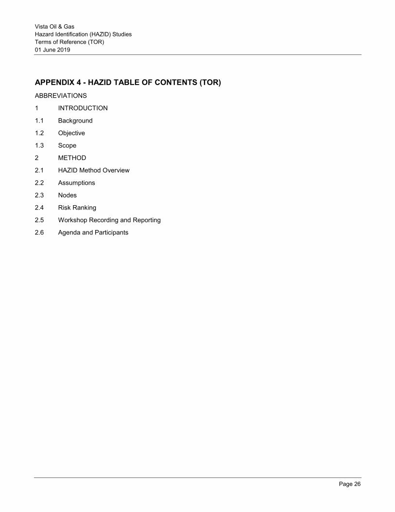
APPENDIX 4 - HAZID TABLE OF CONTENTS (TOR) ABBREVIATIONS
1 INTRODUCTION
1.1 Background
1.2 Objective
1.3 Scope
2 METHOD
2.1 HAZID Method Overview
2.2 Assumptions
2.3 Nodes
2.4 Risk Ranking
2.5 Workshop Recording and Reporting
2.6 Agenda and Participants
Vista Oil & Gas Hazard Identification (HAZID) Studies Terms of Reference (TOR) 01 June 2019
Page 27
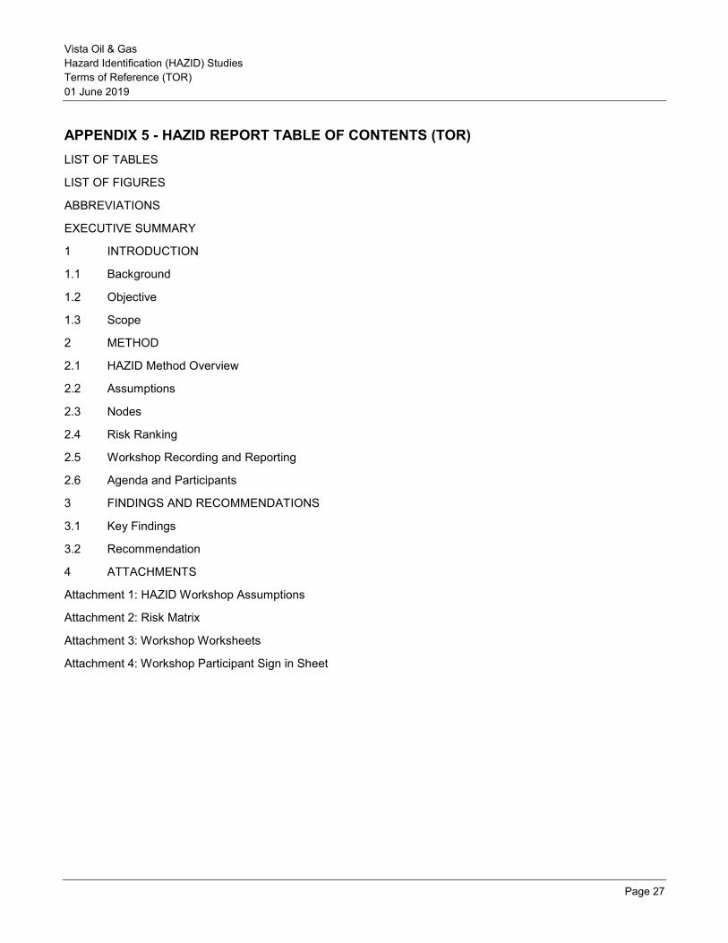
APPENDIX 5 - HAZID REPORT TABLE OF CONTENTS (TOR) LIST OF TABLES
LIST OF FIGURES
ABBREVIATIONS
EXECUTIVE SUMMARY
1 INTRODUCTION
1.1 Background
1.2 Objective
1.3 Scope
2 METHOD
2.1 HAZID Method Overview
2.2 Assumptions
2.3 Nodes
2.4 Risk Ranking
2.5 Workshop Recording and Reporting
2.6 Agenda and Participants
3 FINDINGS AND RECOMMENDATIONS
3.1 Key Findings
3.2 Recommendation
4 ATTACHMENTS
Attachment 1: HAZID Workshop Assumptions
Attachment 2: Risk Matrix
Attachment 3: Workshop Worksheets
Attachment 4: Workshop Participant Sign in Sheet

Vista Oil & Gas Hazard Identification (HAZID) Studies Terms of Reference (TOR) 01 June 2019
Page 28
APPENDIX 6 - HAZID WORKSHOP RECORD SHEET LAYOUT
No. Guideword Hazard Potential
Causes
Potential Conseque
nces
Controls in place
Risk Ranking
Action Items Who When P A C E
Highest Risk
Node 1:
1.01
Node 2:
2.01
Risk Ranking: P: People A: Assets C: Community E: Environment
Vista Oil & Gas Hazard Identification (HAZID) Studies Terms of Reference (TOR) 01 June 2019
Page 29
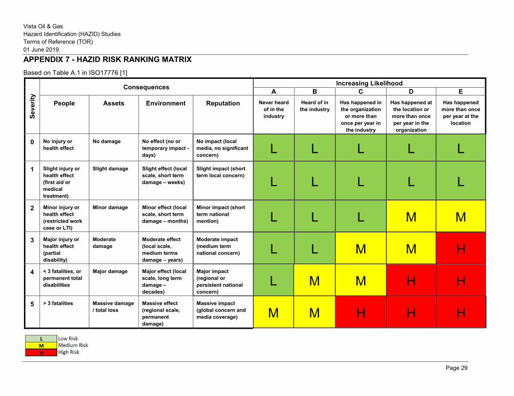
APPENDIX 7 - HAZID RISK RANKING MATRIX Based on Table A.1 in ISO17776 [1]
Seve
rity
Consequences Increasing Likelihood A B C D E
People Assets Environment Reputation Never heard of in the industry
Heard of in the industry
Has happened in the organization
or more than once per year in
the industry
Has happened at the location or more than once per year in the organization
Has happened more than once per year at the
location
0 No injury or health effect
No damage No effect (no or temporary impact - days)
No impact (local media, no significant concern)
L L L L L
1 Slight injury or health effect (first aid or medical treatment)
Slight damage Slight effect (local scale, short term damage – weeks)
Slight impact (short term local concern)
L L L L L
2 Minor injury or health effect (restricted work case or LTI)
Minor damage Minor effect (local scale, short term damage – months)
Minor impact (short term national mention) L L L M M
3 Major injury or health effect (partial disability)
Moderate damage
Moderate effect (local scale, medium terms damage – years)
Moderate impact (medium term national concern) L L M M H
4 < 3 fatalities, or permanent total disabilities
Major damage Major effect (local scale, long term damage – decades)
Major impact (regional or persistent national concern)
L M M H H
5 > 3 fatalities Massive damage / total loss
Massive effect (regional scale, permanent damage)
Massive impact (global concern and media coverage) M M H H H

HAZOP TERMS OF REFERENCE Rev 0
01 June 2019
Vista Oil & Gas HAZOP Terms of Reference (TOR) 01 June 2019
Page 2
Document Revision Status
Revision Description Author Review Approval Date
A Draft for Internal Review
0 Draft for Client Review
Vista Oil & Gas HAZOP Terms of Reference (TOR) 01 June 2019
Page 3
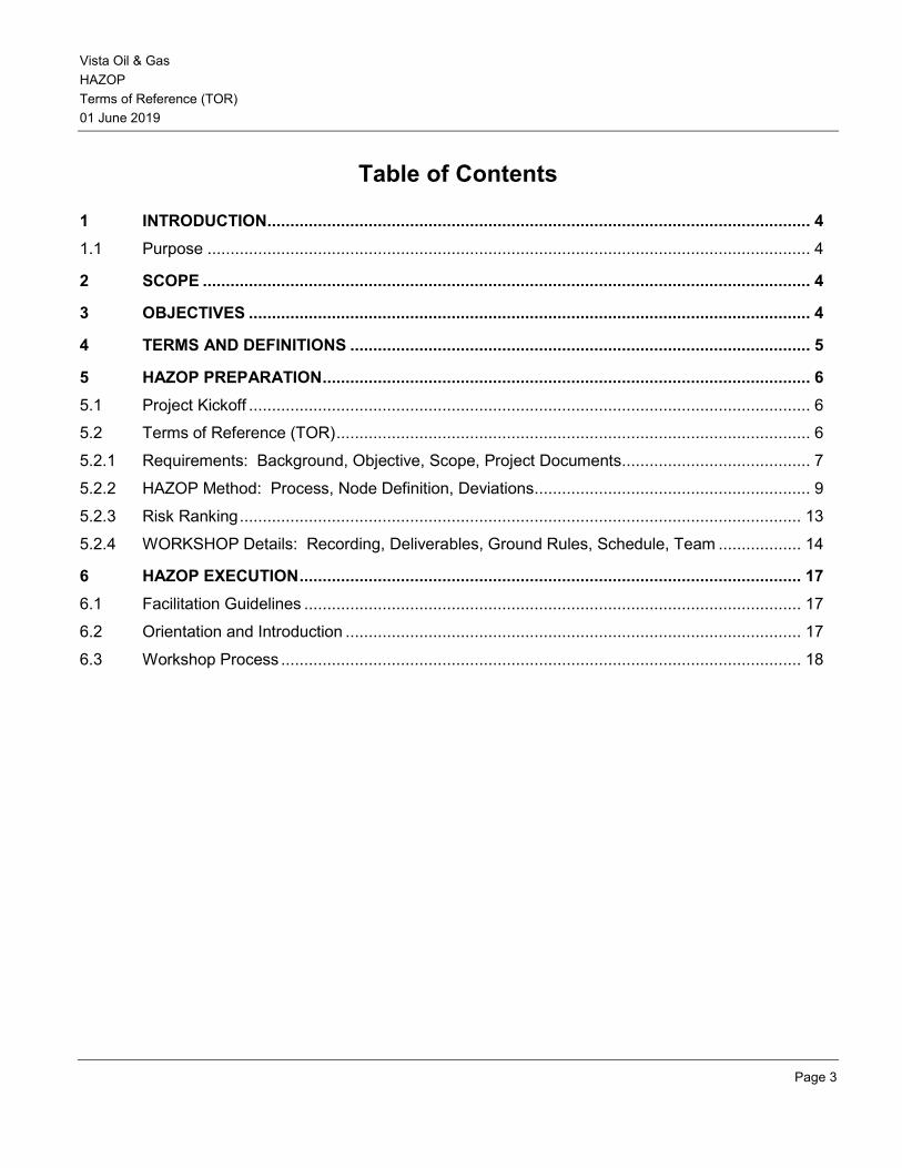
Table of Contents
1 INTRODUCTION ...................................................................................................................... 4
1.1 Purpose ................................................................................................................................... 4
2 SCOPE .................................................................................................................................... 4
3 OBJECTIVES .......................................................................................................................... 4
4 TERMS AND DEFINITIONS .................................................................................................... 5
5 HAZOP PREPARATION .......................................................................................................... 6
5.1 Project Kickoff .......................................................................................................................... 6
5.2 Terms of Reference (TOR) ....................................................................................................... 6
5.2.1 Requirements: Background, Objective, Scope, Project Documents ......................................... 7
5.2.2 HAZOP Method: Process, Node Definition, Deviations............................................................ 9
5.2.3 Risk Ranking .......................................................................................................................... 13
5.2.4 WORKSHOP Details: Recording, Deliverables, Ground Rules, Schedule, Team .................. 14
6 HAZOP EXECUTION ............................................................................................................. 17
6.1 Facilitation Guidelines ............................................................................................................ 17
6.2 Orientation and Introduction ................................................................................................... 17
6.3 Workshop Process ................................................................................................................. 18
Vista Oil & Gas HAZOP Terms of Reference (TOR) 01 June 2019
Page 4
1 INTRODUCTION
1.1 Purpose
Hazard and Operability (HAZOP) Studies is a team workshop based analysis to identify potential safety and environmental hazards and major operability problems. HAZOP is one of the techniques specifically mentioned in some regulations and is generally accepted as one of the preferred hazard identification methodologies in the chemical and petroleum industries.
HAZOP is a methodology used in design and operations to provide a rigorous design integrity assurance process. It is applicable to both major projects and existing operations. HAZOP is a key hazard identification technique because of its systematic approach.
The HAZOP technique was originally developed as a hazard identification tool for chemical processing and petroleum industries. Over recent years, the study areas examined have broadened and the HAZOP process is currently recognized as a suitable technique for application to the following systems and sequences:
• Fluid medium or other material flow (e.g. HAZOP study of process flowlines and vessels)
• Software applications including programmable electronic systems (e.g. HAZOP study for basic process control systems – sometimes referred to as a Control HAZOP)
• Examination of different operating sequences and procedures (e.g. HAZOP study for batch operation or for operating, maintenance, shutdown, sampling or testing procedures – sometimes referred to a Procedural HAZOP)
• Systems involving the movement of people by transport modes such as road and rail (under development)
An understanding of the method used for HAZOP is important to properly prepare and successfully complete the HAZOP workshop, and to help ensure that the HAZOP output is robust, defensible, and useful to the HAZOP owner (Vista Oil).
2 SCOPE
This document provides requirements for the planning, conduction, and documentation of HAZOP studies.
3 OBJECTIVES
The objective of this document is to outline a HAZOP method for use by the HAZOP facilitators, for internal training, and for informational distribution.
Vista Oil & Gas HAZOP Terms of Reference (TOR) 01 June 2019
Page 5
4 TERMS AND DEFINITIONS
For the purposes of this procedure, the following terms and definitions apply:
Cause: Event, situation, or condition that results, or could result, directly or indirectly in an incident.
Consequence: Direct, undesirable result of an incident sequence usually involving a fire, explosion, or release of toxic material. Consequence descriptions may be qualitative or quantitative estimates of the effects of an accident in terms of factors such as health impacts, economic loss, environmental damage, operational impact, and company reputation.
Design intent: How a process or system is supposed to function.
Deviation: Departure from the design intent. A deviation is created by combining a guideword with a parameter.
Guideword: Words such as “high”, “low”, and “no” that are applied to parameters to create a potential deviation from the design intent.
Hazard: Chemical or physical condition or practice with the potential to cause harm to people, the environment, property, or reputation.
Hazard and operability (HAZOP): Systematic qualitative technique, using a series of deviations from the normal process conditions, to identify and evaluate process hazards and potential operating problems.
Node: A clearly defined section of the facility in which the deviations from the process design intent are evaluated.
Operability: Ability to operate a facility inside the design envelope and meet business expectations.
Parameters: Conditions, such as flow, pressure, and temperature, used to define a process.
P&ID: Piping & Instrumentation Diagrams
Risk: A measure of loss or harm to people, the environment, compliance status, reputation, assets, or business performance in terms of the probability of an event occurring and the magnitude of its impact.
Safeguard: Device, system, or action that would likely interrupt the chain of events following an initiating cause or that would mitigate loss event impacts. Safeguards may prevent causes, detect deviations, or mitigate consequences.
Terms of Reference (TOR): A document produced by the HAZOP consultant (with input from Vista Oil) that is an agreement between Vista Oil and the HAZOP facilitator, confirming HAZOP objectives, scope, method, schedule, deliverables, etc. prior to the HAZOP.
Vista Oil & Gas HAZOP Terms of Reference (TOR) 01 June 2019
Page 6
5 HAZOP PREPARATION
HAZOP preparation activities include a project kickoff meeting, preparation and issuance of the Terms of Reference, and a preworkshop meeting between the HAZOP consultant and Vista Oil. These activities are described in the following sections.
5.1 Project Kickoff
A project kick-off meeting is held as soon as possible after the job is awarded to the HAZOP consultant. Participants of the kickoff meeting include, at a minimum, the HAZOP facilitator, the scribe, and one technical representative from Vista Oil. Topics for discussion are based on the approved job proposal and any preliminary communications between Vista Oil and the HAZOP consultant including:
• Project overview (e.g., onshore gas production facility)
• HAZOP objectives and scope
• HAZOP method (e.g., consequence-based with risk ranking)
• Schedule for deliverables
• Any other relevant project issues
5.2 Terms of Reference (TOR)
The Terms of Reference is an agreement between the Vista Oil and the HAZOP facilitator confirming HAZOP objectives, scope, method, schedule, deliverables, etc. prior to the HAZOP
Development of the TOR promotes a consistent understanding of the HAZOP method among HAZOP team members and ensures that application of the method is appropriate to Vista Oil’s goals.
The Terms of Reference incorporates information from the following sources:
• The job proposal (which has been accepted by Vista Oil)
• Base documentation provided by Vista Oil
• Relevant communications between Vista Oil and the HAZOP facilitator
• Kickoff meeting minutes
The TOR should be issued to HAZOP team members prior to the HAZOP workshop.
The TOR also forms the basis of the HAZOP report. As such, it contains all the elements of the project report except for the findings and conclusions. The topics typically included in the TOR are described in the following sections.
Vista Oil & Gas HAZOP Terms of Reference (TOR) 01 June 2019
Page 7
5.2.1 Requirements: Background, Objective, Scope, Project Documents
Background
The TOR includes a brief project description and reason for the HAZOP.
HAZOP Objectives
The objectives of HAZOP are confirmed with Vista Oil prior to the HAZOP and documented in the TOR. HAZOP objectives typically include:
• Systematically identify, assess, and risk rank hazard and operability issues
• Make recommendations to safeguard the process, as required
The HAZOP is not a means for defining engineering and procedural solutions.
HAZOP Scope
The scope of the HAZOP is confirmed with Vista Oil prior to the HAZOP session, and documented in the TOR. The HAZOP scope defines:
• The physical boundaries of the HAZOP (i.e., which systems to include and which to exclude)
• The HAZOP nodes (determined by the HAZOP facilitator with input from Vista Oil as appropriate)
• Which operational modes (e.g., normal, start-up, shut-down, maintenance, sampling) should be considered
• Which impact categories (e.g., personnel safety and health, environmental, commercial, operability, reputation) are of interest to Vista Oil
• Any narrowing of focus for risk ranking, if applicable (see Section 5.2.3)
Project Documentation
Timely provision of project technical documents helps to ensure proper HAZOP preparation and a successful, robust, defensible HAZOP output. The base documentation provided by Vista Oil to the HAZOP consultant generally will be provided at least two weeks prior to the HAZOP.
The TOR lists, at a minimum, the P&IDs used to define the nodes and Vista Oil’s HAZOP procedure. The facility design reflected in the P&IDs should be sufficiently developed and approved for HAZOP by the project team. Any additional documents referenced during HAZOP should be listed in the final HAZOP report.
A list outlining the typical data needs for a HAZOP study is provided below:
• P&IDs: o Vendor packages if within the scope of the HAZOP
Vista Oil & Gas HAZOP Terms of Reference (TOR) 01 June 2019
Page 8
o Piping class specifications o Materials of construction
• PFDs: o Heat and material balances o Inventories o Safe upper and lower operating limits, operating envelopes
• Previous HAZID, What If, HAZOP, or LOPA/SIL reports • Control, alarm, and trip information:
o Alarm and trip settings o Control system philosophy and description o Interlock/trip activation and response descriptions o Shutdown matrices (cause and effect diagrams) o ESD system functions
• Pressure relief, flare, vent, and depressuring information o Relief valve data sheets o Scenarios considered for sizing of the devices o Flare/disposal systems design and sizing information, including comprehensive list of common
failure scenarios (i.e., power failure) and effects on flare loadings and flare system backpressure • Changes to design since the last HAZOP or PHA.
• Operating procedures (startup, operating, shut down, emergency), (required for a procedural HAZOP)
• Previous process safety accident/ incident/ near miss reports • Process description and process chemistry • Facility plot plan/unit layout drawings • Additional documentation may should include the following as applicable:
o Corrosion control guidelines and corrosion and materials diagrams o Pump and compressor operating curves and dead head pressures o Instrumentation data sheets, including control valves, orifices, throttling valves and regulators o Valve capacities - particularly important for gas breakthrough o Fire protection design philosophy and basis o Inspection and testing results, maintenance records, operational history, and current condition
of process equipment o General arrangement and elevation drawings, including electrical area classification and
drainage o Operations and maintenance philosophy
Vista Oil & Gas HAZOP Terms of Reference (TOR) 01 June 2019
Page 9
o Commissioning procedures o Maintenance procedures o Previous risk assessment. In particular, any consequence modelling that has been completed to
assess the consequences of identified causes o Electrical loop diagrams o Process sequence, for batch operations o Ventilation system design o Design codes and standards
5.2.2 HAZOP Method: Process, Node Definition, Deviations
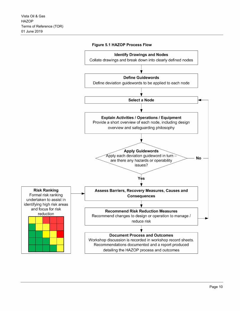
The HAZOP process workflow, shown in Figure 5.1, systematically combines process parameters (e.g., flow, pressure, temperature) with guidewords (e.g., no, high, low, reverse) to produce process deviations from the design intent or intended operation of the facilities.
Vista Oil & Gas HAZOP Terms of Reference (TOR) 01 June 2019
Page 10
Figure 5.1 HAZOP Process Flow

Vista Oil & Gas HAZOP Terms of Reference (TOR) 01 June 2019
Page 11
Node Definition
Typically, nodes are determined by the facilitator during review of the project P&IDs. Guidelines for node definition include:
1. Divide the facility into process systems and subsystems, using a block process diagram, if available
2. Follow the process flow of the system under study, using the PFDs
3. Isolate subsystems into major components which achieve a single objective (e.g., increase/decrease pressure or temperature, remove water or liquids, separate or compress gases, remove contaminants, export liquid or gas )
4. Nodes should be small enough so that team does not lose focus
5. Nodes should be large enough to include at least one major piece of equipment and may include associated equipment (e.g., a node centered on a distillation column may include associated pumps and exchangers)
6. Other considerations such as pressure specification breaks may define node boundaries
7. Time allowed for HAZOP review of each node is 2 to 4 hours
Deviations
The typical deviations applied to each node are listed in Table 5.1[3]
Table 5.1: Typical Deviations
Process Related Deviations Other Deviations
High Pressure Startup / Shutdown
Low Pressure Maintenance (e.g., facility siting issues)
High Flow Sampling
Low / No Flow Others, as appropriate
Reverse Flow
Misdirected Flow
High Level
Low / No Level
High Temperature
Low Temperature
Incorrect Concentration

Vista Oil & Gas HAZOP Terms of Reference (TOR) 01 June 2019
Page 12
Where appropriate, deviations may be added to describe potential events that are particular to that node (e.g., no / low agitation).
Vista Oil & Gas HAZOP Terms of Reference (TOR) 01 June 2019
Page 13
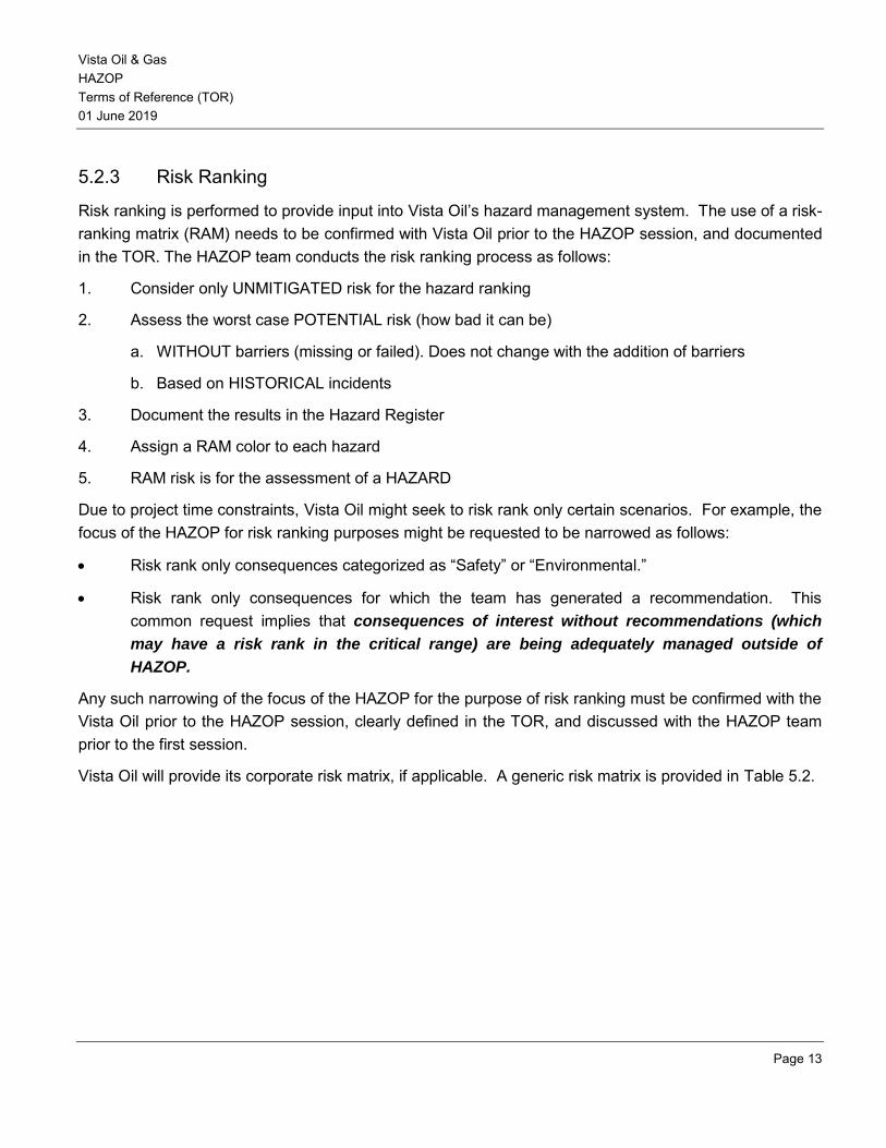
5.2.3 Risk Ranking
Risk ranking is performed to provide input into Vista Oil’s hazard management system. The use of a risk-ranking matrix (RAM) needs to be confirmed with Vista Oil prior to the HAZOP session, and documented in the TOR. The HAZOP team conducts the risk ranking process as follows:
1. Consider only UNMITIGATED risk for the hazard ranking
2. Assess the worst case POTENTIAL risk (how bad it can be)
a. WITHOUT barriers (missing or failed). Does not change with the addition of barriers
b. Based on HISTORICAL incidents
3. Document the results in the Hazard Register
4. Assign a RAM color to each hazard
5. RAM risk is for the assessment of a HAZARD
Due to project time constraints, Vista Oil might seek to risk rank only certain scenarios. For example, the focus of the HAZOP for risk ranking purposes might be requested to be narrowed as follows:
• Risk rank only consequences categorized as “Safety” or “Environmental.”
• Risk rank only consequences for which the team has generated a recommendation. This common request implies that consequences of interest without recommendations (which
may have a risk rank in the critical range) are being adequately managed outside of
HAZOP.
Any such narrowing of the focus of the HAZOP for the purpose of risk ranking must be confirmed with the Vista Oil prior to the HAZOP session, clearly defined in the TOR, and discussed with the HAZOP team prior to the first session.
Vista Oil will provide its corporate risk matrix, if applicable. A generic risk matrix is provided in Table 5.2.

Vista Oil & Gas HAZOP Terms of Reference (TOR) 01 June 2019
Page 14
Table 5.2: Typical Risk Ranking Matrix (RAM)
5.2.4 WORKSHOP Details: Recording, Deliverables, Ground Rules, Schedule, Team
Workshop Recording and Deliverables
The HAZOP study report serves as the permanent record of the HAZOP study. It is usually used by people that were not part of the HAZOP study team. Over time, the HAZOP report is the only indicator of the quality and completeness of the HAZOP study and serves as a record of the team diligence. It is important that the HAZOP leader have the attention to detail to ensure clarity and accuracy of the worksheets and report.
Recording by ‘exception’. Whilst this may save time by recording only those deviations that result in a recommendation, it does not provide documentation of the dependence of safeguards, and it is impossible to revalidate or review the discussions made by the HAZOP team. It also does not provide an auditable trail of the HAZOP and a record of whether the deviation was considered or not.
Vista Oil & Gas HAZOP Terms of Reference (TOR) 01 June 2019
Page 15
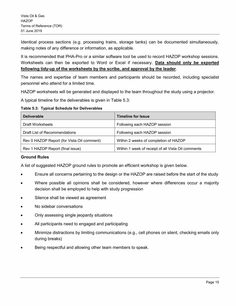
Identical process sections (e.g. processing trains, storage tanks) can be documented simultaneously, making notes of any difference or information, as applicable.
It is recommended that PHA-Pro or a similar software tool be used to record HAZOP workshop sessions. Worksheets can then be exported to Word or Excel if necessary. Data should only be exported following tidy-up of the worksheets by the scribe, and approval by the leader.
The names and expertise of team members and participants should be recorded, including specialist personnel who attend for a limited time.
HAZOP worksheets will be generated and displayed to the team throughout the study using a projector.
A typical timeline for the deliverables is given in Table 5.3:
Table 5.3: Typical Schedule for Deliverables
Deliverable Timeline for Issue
Draft Worksheets Following each HAZOP session
Draft List of Recommendations Following each HAZOP session
Rev 0 HAZOP Report (for Vista Oil comment) Within 2 weeks of completion of HAZOP
Rev 1 HAZOP Report (final issue) Within 1 week of receipt of all Vista Oil comments
Ground Rules
A list of suggested HAZOP ground rules to promote an efficient workshop is given below.
• Ensure all concerns pertaining to the design or the HAZOP are raised before the start of the study
• Where possible all opinions shall be considered, however where differences occur a majority decision shall be employed to help with study progression
• Silence shall be viewed as agreement
• No sidebar conversations
• Only assessing single jeopardy situations
• All participants need to engaged and participating
• Minimize distractions by limiting communications (e.g., cell phones on silent, checking emails only during breaks)
• Being respectful and allowing other team members to speak.
Vista Oil & Gas HAZOP Terms of Reference (TOR) 01 June 2019
Page 16
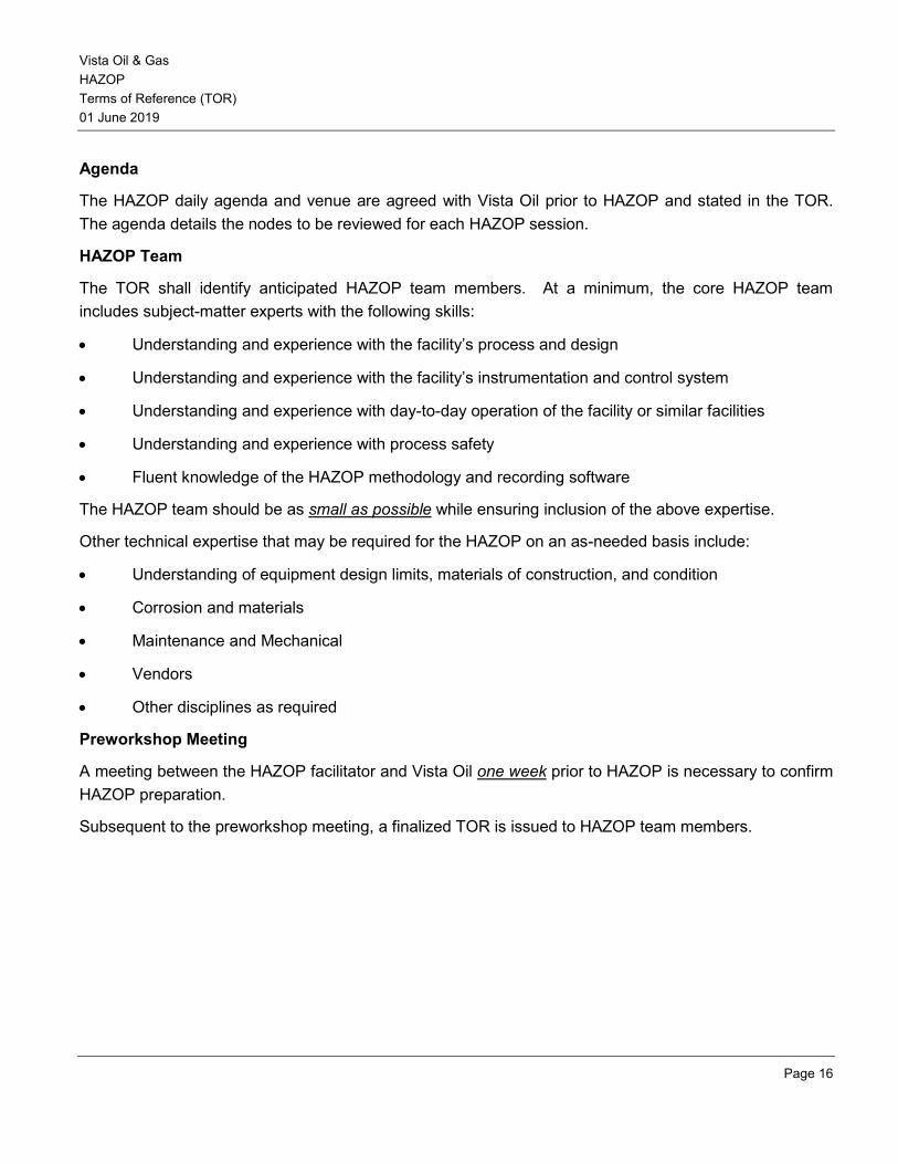
Agenda
The HAZOP daily agenda and venue are agreed with Vista Oil prior to HAZOP and stated in the TOR. The agenda details the nodes to be reviewed for each HAZOP session.
HAZOP Team
The TOR shall identify anticipated HAZOP team members. At a minimum, the core HAZOP team includes subject-matter experts with the following skills:
• Understanding and experience with the facility’s process and design
• Understanding and experience with the facility’s instrumentation and control system
• Understanding and experience with day-to-day operation of the facility or similar facilities
• Understanding and experience with process safety
• Fluent knowledge of the HAZOP methodology and recording software
The HAZOP team should be as small as possible while ensuring inclusion of the above expertise.
Other technical expertise that may be required for the HAZOP on an as-needed basis include:
• Understanding of equipment design limits, materials of construction, and condition
• Corrosion and materials
• Maintenance and Mechanical
• Vendors
• Other disciplines as required
Preworkshop Meeting
A meeting between the HAZOP facilitator and Vista Oil one week prior to HAZOP is necessary to confirm HAZOP preparation.
Subsequent to the preworkshop meeting, a finalized TOR is issued to HAZOP team members.
Vista Oil & Gas HAZOP Terms of Reference (TOR) 01 June 2019
Page 17
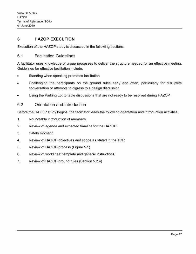
6 HAZOP EXECUTION
Execution of the HAZOP study is discussed in the following sections.
6.1 Facilitation Guidelines
A facilitator uses knowledge of group processes to deliver the structure needed for an effective meeting. Guidelines for effective facilitation include:
• Standing when speaking promotes facilitation
• Challenging the participants on the ground rules early and often, particularly for disruptive conversation or attempts to digress to a design discussion
• Using the Parking Lot to table discussions that are not ready to be resolved during HAZOP
6.2 Orientation and Introduction
Before the HAZOP study begins, the facilitator leads the following orientation and introduction activities:
1. Roundtable introduction of members
2. Review of agenda and expected timeline for the HAZOP
3. Safety moment
4. Review of HAZOP objectives and scope as stated in the TOR
5. Review of HAZOP process (Figure 5.1)
6. Review of worksheet template and general instructions
7. Review of HAZOP ground rules (Section 5.2.4)
Vista Oil & Gas HAZOP Terms of Reference (TOR) 01 June 2019
Page 18
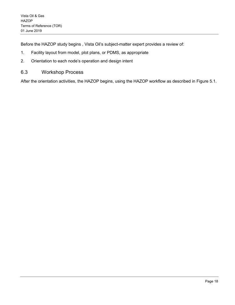
Before the HAZOP study begins , Vista Oil’s subject-matter expert provides a review of:
1. Facility layout from model, plot plans, or PDMS, as appropriate
2. Orientation to each node’s operation and design intent
6.3 Workshop Process
After the orientation activities, the HAZOP begins, using the HAZOP workflow as described in Figure 5.1.
Vista Oil & Gas HAZOP Terms of Reference (TOR) 01 June 2019
Page 19
REFERENCES
The reader is referred to the following sources for further information:
[1] T. Kletz, HAZOP and HAZAN - Identifying and Assessing Process Industry Hazards,4th edition, New York: Taylor & Francis, 1999.
[2] S. Mannan, ed., Lees' Loss Prevention in the Process Industries: Hazard Identification, Assessment and Control, 3rd edition, Burlington, MA: Elsevier, 2005.
[3] Guidelines for Hazard Evaluation Procedures, with Worked Examples, 2nd edition, CCPS, 1992.
BLOWOUT RISK ASSESSMENT - TERMS OF REFERENCE
Rev 0
01 June 2019
Vista Oil & Gas Blowout Risk Assessment Terms of Reference (TOR) 01 June 2019
Page 2
Document Revision Status
Revision Description Author Review Approval Date
A Draft for Internal Review
0 Draft for Client Review
Vista Oil & Gas Blowout Risk Assessment Terms of Reference (TOR) 01 June 2019
Page 3
Table of Contents
1 INTRODUCTION ...................................................................................................................... 4
1.1 Purpose ................................................................................................................................... 4
2 SCOPE .................................................................................................................................... 4
3 OBJECTIVE ............................................................................................................................. 4
4 THE STUDY ............................................................................................................................. 5
4.1 Principles of the Blowout Risk Assessment .............................................................................. 5
4.2 Basic Scenarios Considered .................................................................................................... 5
4.3 Blowout Frequency Analysis .................................................................................................... 6
4.4 Blowout Ignition Probability ...................................................................................................... 6
4.5 Blowout Consequence Analysis ............................................................................................... 6
4.6 Preventive and Mitigation Measures ......................................................................................... 7
5 THE REPORT .......................................................................................................................... 7
5.1 Study Title Page ....................................................................................................................... 8
5.2 Table of Contents ..................................................................................................................... 8
5.3 Summary of Main Findings and Recommendations ................................................................. 8
5.4 Glossary and Abbreviations ..................................................................................................... 8
5.5 Scope of Report ....................................................................................................................... 8
5.6 Description of the Facility ......................................................................................................... 9
5.7 Hazards Identified .................................................................................................................... 9
5.8 Consequences of Incidents ...................................................................................................... 9
5.9 Blowout Prevention Strategies/Measures ................................................................................. 9
5.10 Details of Detection and Protection ........................................................................................ 10
5.11 Results and Conclusions ........................................................................................................ 10
5.12 Codes and Standards ............................................................................................................ 10
5.13 Appendices ............................................................................................................................ 10
Vista Oil & Gas Blowout Risk Assessment Terms of Reference (TOR) 01 June 2019
Page 4
1 INTRODUCTION
1.1 Purpose
The blowout risk assessment’s objective is to provide the most conservative analysis possible of the risks related to well control due to drilling of oil & gas wells by identifying the consequences of such risks and the mitigation measures that can be implemented to reduce the likelihood of uncontrolled flow of the reservoir fluids. Loss of well control / blow-out and process leaks constitute the major potential hazards that may be associated with the onshore drilling leading to pool/jet fires.
The blowout risk assessment is one element in the safety assurance process. Emergency planning is also an important element and its relationship to safety arrangements should be clearly dealt with in the study and the report.
The study involves case-specific hazard analyses and design of safety arrangements to meet those hazards. The approach is particularly important where significant quantities of hazardous materials are involved. The level of detail warranted for each element of this assessment will vary with the nature and scale of the hazard. The case-specific approach offers the benefit that the safety measures can be tailor- made and cost effective.
2 SCOPE
This document provides requirements for the planning, conduction, and documentation of a Blowout Risk
Assessment.
3 OBJECTIVE
The objective of this document is to outline a method to carry out a Blowout Risk Assessment, including the format of the report. Such study is required as part of the overall safety assessment of development and building proposals and also used in the blowout risk assessment of existing wells.
Vista Oil & Gas Blowout Risk Assessment Terms of Reference (TOR) 01 June 2019
Page 5
4 THE STUDY
4.1 Principles of the Blowout Risk Assessment
The blowout risk assessment has to be performed for all the blowout scenarios that can result in a major hazard event. This assessment has to be done for all the locations of interest. Some of the leading causes of blowout events include failure to manage the kicks, failure of BOP equipment and poor drilling practices.
The initial step in blowout risk assessment is to determine the blowout characteristics such as flow rates, durations, etc. that are considered as the basic input parameters for this analysis. These parameters can be extracted from available historical statistics from blowout databases or from the database from similar facility if available as historical database provides generic data with limited consideration for specific operations. Well parameters and blowout preventer (BOP) are the two major factors to be considered while evaluating the blowout risks. Weather data for the location of the facility including the wind stability conditions, temperature, etc. has to be collected from the national weather for the purpose of the assessment.
Potential events are analyzed using the unified dispersion model PHAST or a similar tool that can model the progress of a potential incident from the initial release to the far-field dispersion including pool spreading, evaporation and flammable effects.
Once the risk assessment has been performed to identify the risks and severity of the outcome, a threshold for acceptable risks has to be established to identify the acceptable risks and unacceptable risks. The final step would be to determine if unacceptable risks can be mitigated to as low as reasonable practicable (ALARP).
4.2 Basic Scenarios Considered
Blowout is a most catastrophic occurrence that could cause during well site operations that may or may not result in a fire. The following are some of the scenarios where a well blowout can occur:
• During drilling operations
• During workover operations
• During production operations
• During completion operations
• Due to deteriorated surface equipment
Vista Oil & Gas Blowout Risk Assessment Terms of Reference (TOR) 01 June 2019
Page 6
4.3 Blowout Frequency Analysis
Blow out frequency estimates is obtained from a combination of incident experience and associated exposure in a given area over a given period. Frequencies for the events studied has to be calculated to provide a basis for prioritizing risk management considerations. Blowout frequencies are generally calculated on a per well basis using publically available data. Data from the International Association of Oil & Natural Gas Producers (OGP) or Risk Assessment Data Directory (RADD), which is an extensive database generally acknowledged to be an excellent source of data for well incidents, is based on conventional vertical wells. This data can also be used to calculate the percentage of blowouts that can ignite based on the blowout fires recorded.
For blowouts, calculation of the explosion frequency may not be required, as the worst case event will be the jet fire, and any explosion incident would also flash back to the well, resulting in a jet fire. The frequency of ignited blowouts and ignited flowback line failure can be estimated as equivalent to about one per the number of wells drilled. These frequencies will be then multiplied by the number of wells being drilled. If the well campaign is less than 12 months, the corresponding annualized frequency (which can be used to compare risk levels to personnel on the site, or to surrounding areas) would be increased – that is, if the campaign takes 6 months, the equivalent annualized frequency is the per well frequency multiplied by two.
Frequencies for completions events are based on a full year of service, and so would be factored down for the amount of time present. For instance, if onsite and in service for 3 months, the frequency would be multiplied by 3/12. The calculated frequencies shall be presented from the analysis.
4.4 Blowout Ignition Probability
Review of database such as SINTEF or OGP shall be used to estimate the ignition probability of the blowout events. For example, as per SINTEF database generally ignition occurred within first 5 minutes in approximately 40% of the blowouts leading to either pool and/or jet fire. Blow out leading to flammable gas release has a greater probability of ignition compared to liquid releases.
4.5 Blowout Consequence Analysis
Blowout from a hydrocarbon well may lead to the following possible risk consequences:
• Pool fires and smoke plumes resulting from ignited oil blow outs
• Jet fires resulting from ignited gas blow outs
• Oil slicks resulting from un-ignited oil pools
Modeling shall be based on methane which is considered as the principle constituent of natural gas from the gas wells leading to fire.
Vista Oil & Gas Blowout Risk Assessment Terms of Reference (TOR) 01 June 2019
Page 7
Weather data from the collected database as wind speed and stability categories need to be used for the consequence runs. Thermal radiation levels of concern for worst case weather conditions has to be analyzed during the blowout risk assessment.
For a blowout scenario the fire effect distance is the driving force due to lift of the cloud limiting overpressure effects at ground level. The levels to be studied for worst case scenarios shall include:
• 1 psi - Glass breakage; major damage to lightwood trailers; impairment threshold for permanent structures; fatality threshold for personnel inside impaired structures.
• 3 psi - Major damage to permanent structures; fatality threshold for people outside.
• 5 psi - Destruction of non-blast rated permanent structures; utility poles snapped; threshold for damage to mechanical equipment.
4.6 Preventive and Mitigation Measures
The most basic element of well safety is prevention. Blowouts being events which may be catastrophic to any well operation, it is essential to take up as much a preventive measures as feasible.
Examples of matters which should be considered as part of prevention include: • Necessary active barriers (eg. Well-designed Blowout Preventor) installed to control or contain a
potential blowout. • Weekly blow out drills carried out to test reliability of BOP and preparedness of drilling team. • Close monitoring of drilling activity done to check for signs of increasing pressure, like from shallow
gas formations. • Installation of hydrocarbon detectors. • Periodic monitoring and preventive maintenance undertaken for primary and secondary barriers
installed for blow out prevention, including third party inspection & testing • An appropriate Emergency Response Plan finalized and implemented by the owner. • Marking of hazardous zone (500 meters) around the well site and monitoring of human movements in
the zone. • Training and capacity building exercises/programs carried out for onsite drilling crew on potential risks
associated with exploration drilling and their possible mitigation measures. • Installation of mass communication and public address equipment. • Good layout of well site and escape routes.
5 THE REPORT
The report should provide sufficient information on each element so that, either read alone or together with available and clearly cross-referenced documents, an assessment of the adequacy of blowout
Vista Oil & Gas Blowout Risk Assessment Terms of Reference (TOR) 01 June 2019
Page 8
prevention, detection, protection and preventive measures can be made. This section outlines the recommended format and content of the report.
A new page should be started for each section of the report.
5.1 Study Title Page
The study title should be clearly shown on both the cover and on a separate title sheet. The title should clearly and unambiguously identify the facility covered by the study: the type of operation, whether it is a proposed operation or an existing facility and its location. The title sheet should also show who prepared the study, on whose authority and the date.
5.2 Table of Contents
An easy to read table of contents with page numbers should be included at the beginning of the study. It should also include a list of figures and appendices.
5.3 Summary of Main Findings and Recommendations
The summary should briefly outline the nature of the proposed or existing facility, the scope of the report and the matters addressed. It should present in point form the main findings and, where appropriate, recommendations for action.
An implementation program agreed to by the proponent company or the owner or operator should be included. If any recommendations are not to be proceeded with reasons, they should be given.
5.4 Glossary and Abbreviations
To ensure that the study can be understood, a glossary of any special terms, titles of personnel, names of parts of the plant and a list of abbreviations used should be included. For example:
5.5 Scope of Report
This section should give a brief description of the aims and purpose of the study and the reason for its preparation. For example, is it for an entirely new development, the modification of or extension to an existing development, or the establishment of adequacy of blowout safety for an existing development? Is part or alI of the site addressed?
Reference should be made to any other relevant safety related studies previously carried out or under preparation.
Vista Oil & Gas Blowout Risk Assessment Terms of Reference (TOR) 01 June 2019
Page 9
5.6 Description of the Facility
This section should give an overview of the site, plant, buildings and substances used/stored. Design and construction standards must be addressed. Where this information is already available through an environmental impact statement (EIS), hazard analysis or other document, clear cross-reference to these documents and/or supply of copies as necessary would suffice.
The description should include: a) Details of the facility (general description) including brief process description where applicable; b) A generalized outline of the materials and quantities which are, or will be, stored or in process on site; c) A brief description of adjacent/surrounding land uses; and d) Number of people typically on the site and hours of operation.
5.7 Hazards Identified
The possible blow out cause events occurring in isolation or in combination should be provided. The most common cause of blow out can be associated with the sudden/unexpected entry/release of formation fluid into well bore that may arise as a result of any of the events. An example of events may be: • Shallow gas • High formation pressure • Insufficient mud weight
5.8 Consequences of Incidents
The estimated consequences of potential hazardous incidents, as developed in the study, should be detailed. Where applicable, diagrams showing worst case scenario heat flux distances, explosion overpressures and toxicity effects must be included. Such information should be time related where applicable. Consequence and risk contours used in the detailed quantitative risk analysis must be included.
The potential for fire propagation without blowout protection measures should be detailed.
5.9 Blowout Prevention Strategies/Measures
The full range of prevention strategies and measures identified in the study, as outlined in Section ¡Error!
No se encuentra el origen de la referencia., should be described.
Compliance with, or departures from, regulations and standards should be detailed. The justification for departures should be clearly set out.
Vista Oil & Gas Blowout Risk Assessment Terms of Reference (TOR) 01 June 2019
Page 10
Reference to an emergency response plan should be given if one has been prepared for the facility/site or is being written in conjunction with the fire safety study.
5.10 Details of Detection and Protection
The detection and protection systems selected should be detailed and justified in this section.
The analysis in the study, as outlined in sections ¡Error! No se encuentra el origen de la referencia. and ¡Error! No se encuentra el origen de la referencia., forms the basis of this section of the report.
Where applicable the detailing of detection and protection systems should be supported with drawings. Such drawings should be bound in to the report or enclosed in a securely attached pocket or pouch.
5.11 Results and Conclusions
This section presents the results of the risk assessment and the threshold for acceptable risks. This section also discusses the risk mitigation measures to be implemented to mitigate the unacceptable risks to ALARP.
5.12 Codes and Standards
The various codes and standards used in the design and operation of the facility should be listed, and any exceptions or departures from the standards detailed and justified. Where codes and standards are not generally available, copies should be attached to the study (for example, specific company standards or insurance requirements).
5.13 Appendices
To support the content of the document, the following should be included as appendices: • Worst-case discharge estimation • Alternate-case discharge estimation • Modeling calculations; • Drawings referred to in text; and • Reference list
Vista Oil & Gas Blowout Risk Assessment Terms of Reference (TOR) 01 June 2019
Page 11
REFERENCES
The reader is referred to the following sources for further information:
[1] Blowouts: Causes and Control, Per Holand, P, Gulf Publishing Company, Houston (1997).
[2] A Guide to Quantitative Risk Assessment for Offshore Installations, The Centre for Marine and Petroleum Technology (CMPT), 1999.
[3] UK HSE, Reducing Risk Protecting People, HSE Decision Making Process, 2001.
[4] Offshore Reliability Data (OREDA) Handbook, Sintef Technology and Society, 1992.
FIRE SAFETY STUDY - TERMS OF REFERENCE
Rev 0
01 June 2019
Vista Oil & Gas Fire Safety Study Terms of Reference (TOR) 01 June 2019
Page 2
Document Revision Status
Revision Description Author Review Approval Date
A Draft for Internal Review
0 Draft for Client Review
Vista Oil & Gas Fire Safety Study Terms of Reference (TOR) 01 June 2019
Page 3
Table of Contents
1 INTRODUCTION ...................................................................................................................... 5
1.1 Purpose ................................................................................................................................... 5
2 SCOPE .................................................................................................................................... 5
3 OBJECTIVE ............................................................................................................................. 5
4 THE STUDY ............................................................................................................................. 6
4.1 Principles of the Fire Safety Study ........................................................................................... 6
4.2 Identification of Fire Hazards .................................................................................................... 8
4.3 Analysis of Consequences of Incidents .................................................................................... 8
4.4 Fire Prevention Strategies/Measures ....................................................................................... 9
4.5 Analysis of Requirements for Fire Detection and Protection ................................................... 10
4.6 Detection and Protection Measures to be Implemented ......................................................... 11
4.7 Fire Fighting Water Demand and Supply ................................................................................ 11
4.8 Containment of Contaminated Fire Fighting Water ................................................................. 12
4.9 First Aid Fire Protection Arrangements and Equipment .......................................................... 12
5 THE REPORT ........................................................................................................................ 13
5.1 Study Title Page ..................................................................................................................... 13
5.2 Table of Contents ................................................................................................................... 13
5.3 Summary of Main Findings and Recommendations ............................................................... 13
5.4 Glossary and Abbreviations ................................................................................................... 14
5.5 Scope of Report ..................................................................................................................... 14
5.6 Description of the Facility ....................................................................................................... 14
5.7 Hazards Identified .................................................................................................................. 15
5.8 Consequences of Incidents .................................................................................................... 15
5.9 Fire Prevention Strategies/Measures ..................................................................................... 15
5.10 Details of Detection and Protection ........................................................................................ 16
5.11 Detailed Drawings of Fire Services Layout ............................................................................. 16
5.12 Detailed Hydraulic Calculations for Fire-Fighting Water .......................................................... 17
5.13 Arrangements for Containing Contaminated Fire Fighting Water ............................................ 17
5.14 First Aid Fire Protection .......................................................................................................... 17

Vista Oil & Gas Fire Safety Study Terms of Reference (TOR) 01 June 2019
Page 4
5.15 Codes and References........................................................................................................... 17
5.16 Appendices ............................................................................................................................ 17
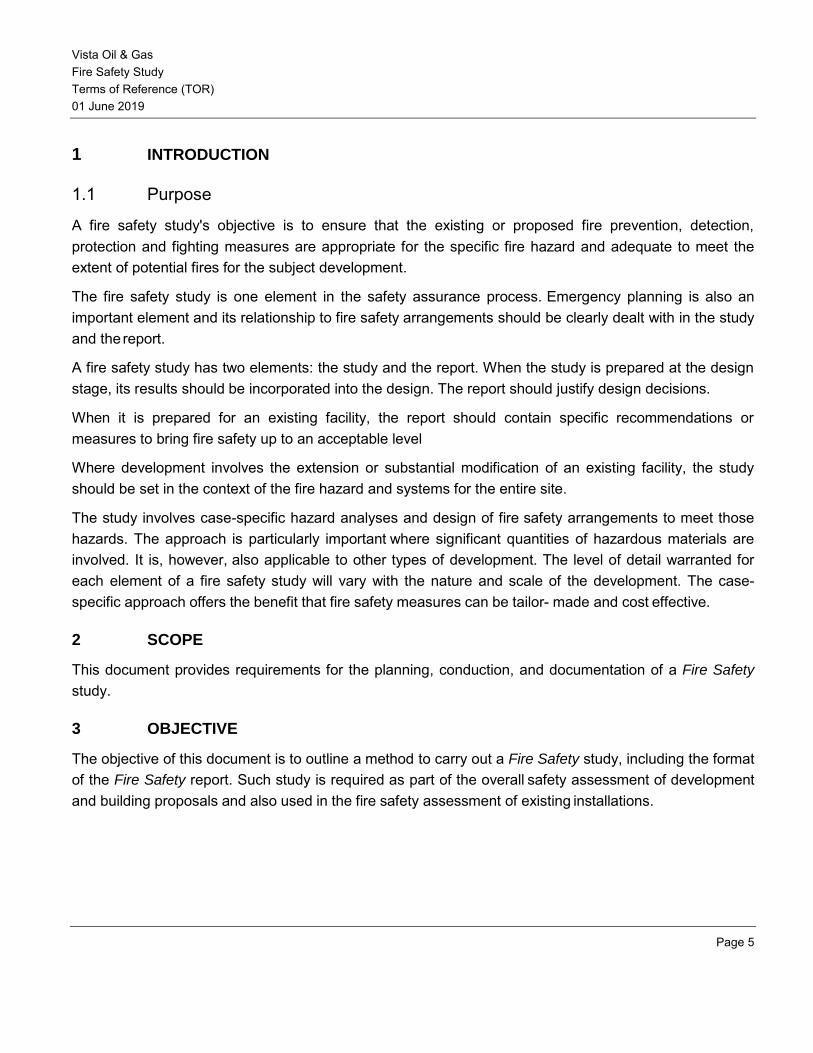
Vista Oil & Gas Fire Safety Study Terms of Reference (TOR) 01 June 2019
Page 5
1 INTRODUCTION
1.1 Purpose
A fire safety study's objective is to ensure that the existing or proposed fire prevention, detection, protection and fighting measures are appropriate for the specific fire hazard and adequate to meet the extent of potential fires for the subject development.
The fire safety study is one element in the safety assurance process. Emergency planning is also an important element and its relationship to fire safety arrangements should be clearly dealt with in the study and the report.
A fire safety study has two elements: the study and the report. When the study is prepared at the design stage, its results should be incorporated into the design. The report should justify design decisions.
When it is prepared for an existing facility, the report should contain specific recommendations or measures to bring fire safety up to an acceptable level
Where development involves the extension or substantial modification of an existing facility, the study should be set in the context of the fire hazard and systems for the entire site.
The study involves case-specific hazard analyses and design of fire safety arrangements to meet those hazards. The approach is particularly important where significant quantities of hazardous materials are involved. It is, however, also applicable to other types of development. The level of detail warranted for each element of a fire safety study will vary with the nature and scale of the development. The case-specific approach offers the benefit that fire safety measures can be tailor- made and cost effective.
2 SCOPE
This document provides requirements for the planning, conduction, and documentation of a Fire Safety study.
3 OBJECTIVE
The objective of this document is to outline a method to carry out a Fire Safety study, including the format of the Fire Safety report. Such study is required as part of the overall safety assessment of development and building proposals and also used in the fire safety assessment of existing installations.
Vista Oil & Gas Fire Safety Study Terms of Reference (TOR) 01 June 2019
Page 6
4 THE STUDY
4.1 Principles of the Fire Safety Study
There are two components to a fire system: the physical or hardware components (for example, smoke detectors, alarms and fire sprinklers) and the operational arrangements or software (for example, maintenance, testing, training and emergency planning).
The principle of a fire safety study is that the fire safety system should be based on specific analysis of hazards and consequences and that the elements of the proposed or existing system should be tested against that analysis. This should always produce a better outcome than the application of generalized codes and standards alone.
Defining the hazard potential of a plant and/or operations involves the process of hazard identification and estimation of the potential consequences of credible incidents.
The fire safety study should be concerned with all the effects of fire. It therefore should not only address the direct effects of flame, radiant heat and explosion but also the potential for the release of toxic materials and toxic combustion products in the event of fire and the potential for the release of contaminated firefighting water.
The fire protection requirement should be based on the worst case scenario(s).
A flow diagram for a typical fire safety study is shown on Figure 4.1.
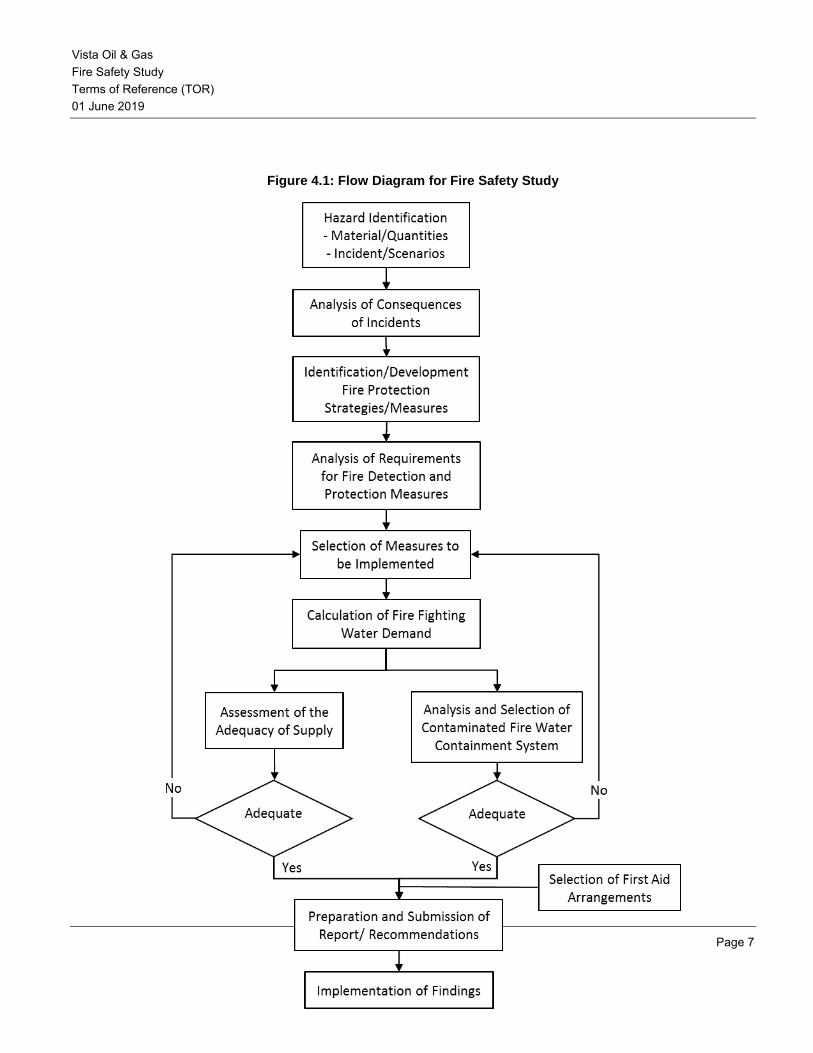
Vista Oil & Gas Fire Safety Study Terms of Reference (TOR) 01 June 2019
Page 7
Figure 4.1: Flow Diagram for Fire Safety Study

Vista Oil & Gas Fire Safety Study Terms of Reference (TOR) 01 June 2019
Page 8
4.2 Identification of Fire Hazards
The first step in the study involves the identification of all possibly hazardous materials, processes and incidents; in particular, those associated with flammables and combustibles. The possible internal and external causes of incidents should also be identified. A Preliminary Hazard Analysis (e.g., HAZID) and a HAZOP should be used for guidance in the hazard identification process.
For example, if a storage terminal has tanks containing flammable liquids, then the possibility of tank fires, bund fires, fires due to pipe and pump failure, fires in loading or drum filling operations and so on must be considered. Similarly, if a plant processes and stores large quantities of liquefied flammable gases then the possibility of jet fires, vapour cloud explosions, flash fires and boiling liquid expanding vapour explosions (BLEVEs) must be addressed. In the case of storage of materials with potential for generating toxic combustion products and/or contaminated water runoff, these hazards must be addressed.
The analysis should cover the nature of the materials and quantities involved, the nature of hazardous events (such as the loss of containment), potential initiating events, ignition sources and so on.
It is important that the possibility of the site being exposed to hazards external to the site is dealt with.
4.3 Analysis of Consequences of Incidents
Once the hazards have been identified, the consequences of incidents can be estimated. The consequence analysis should address both the direct impacts of incidents and the potential for propagation and secondary incidents. The analysis should relate selected targets such as people, equipment or buildings to specific time related exposures (heat flux, explosion overpressure, toxic concentrations and so on).
Justification must be given for the selection of targets, exposures and models used in the consequence calculation.
There are various models available for estimating the consequences of events. Generally, each model has a range of applicability outside of which its use is inappropriate. All models and assumptions used to estimate consequences should be justified.
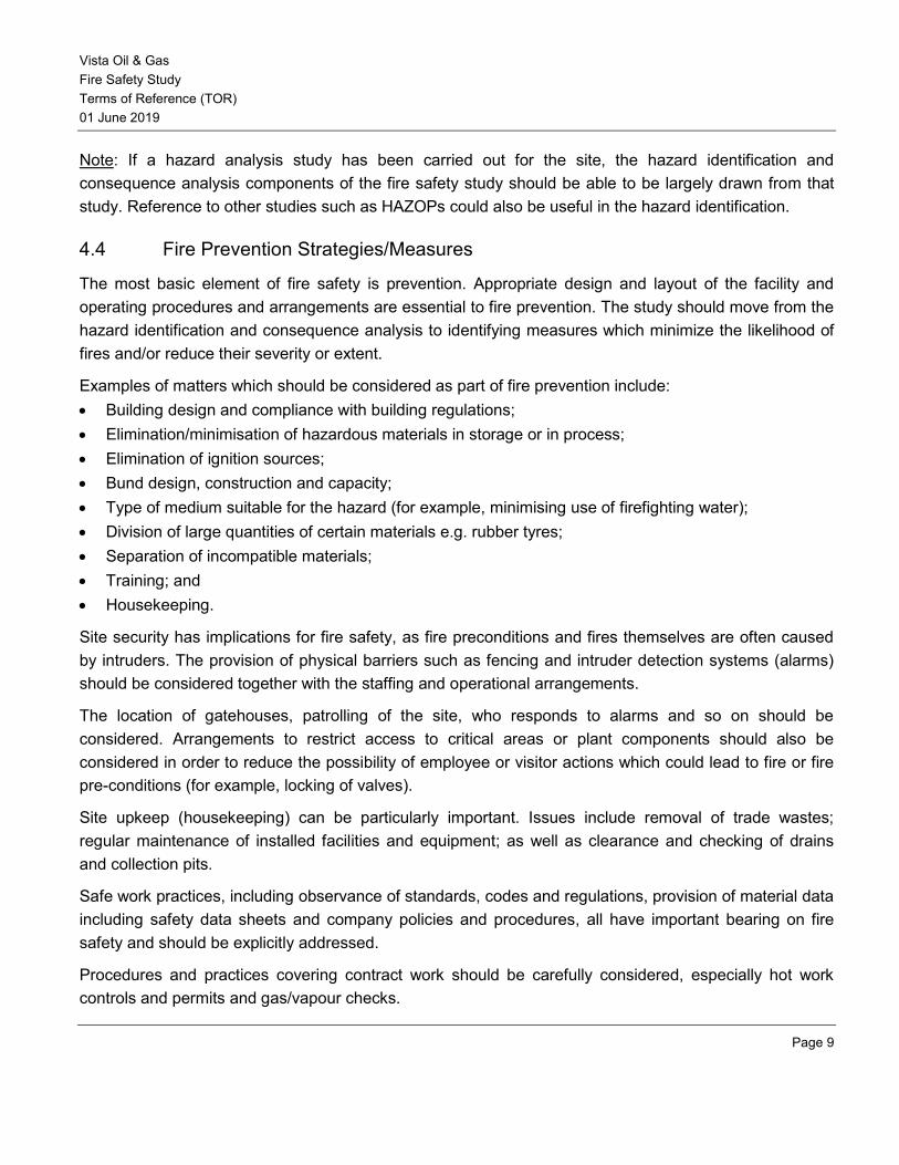
Vista Oil & Gas Fire Safety Study Terms of Reference (TOR) 01 June 2019
Page 9
Note: If a hazard analysis study has been carried out for the site, the hazard identification and consequence analysis components of the fire safety study should be able to be largely drawn from that study. Reference to other studies such as HAZOPs could also be useful in the hazard identification.
4.4 Fire Prevention Strategies/Measures
The most basic element of fire safety is prevention. Appropriate design and layout of the facility and operating procedures and arrangements are essential to fire prevention. The study should move from the hazard identification and consequence analysis to identifying measures which minimize the likelihood of fires and/or reduce their severity or extent.
Examples of matters which should be considered as part of fire prevention include: • Building design and compliance with building regulations; • Elimination/minimisation of hazardous materials in storage or in process; • Elimination of ignition sources; • Bund design, construction and capacity; • Type of medium suitable for the hazard (for example, minimising use of firefighting water); • Division of large quantities of certain materials e.g. rubber tyres; • Separation of incompatible materials; • Training; and • Housekeeping.
Site security has implications for fire safety, as fire preconditions and fires themselves are often caused by intruders. The provision of physical barriers such as fencing and intruder detection systems (alarms) should be considered together with the staffing and operational arrangements.
The location of gatehouses, patrolling of the site, who responds to alarms and so on should be considered. Arrangements to restrict access to critical areas or plant components should also be considered in order to reduce the possibility of employee or visitor actions which could lead to fire or fire pre-conditions (for example, locking of valves).
Site upkeep (housekeeping) can be particularly important. Issues include removal of trade wastes; regular maintenance of installed facilities and equipment; as well as clearance and checking of drains and collection pits.
Safe work practices, including observance of standards, codes and regulations, provision of material data including safety data sheets and company policies and procedures, all have important bearing on fire safety and should be explicitly addressed.
Procedures and practices covering contract work should be carefully considered, especially hot work controls and permits and gas/vapour checks.

Vista Oil & Gas Fire Safety Study Terms of Reference (TOR) 01 June 2019
Page 10
Appropriate emergency plans and procedures are an important part of fire prevention. Appropriate and early action can prevent small incidents developing into serious situations and can limit the scale and extent of the impact of incidents. The development or analysis of fire prevention strategies and measures should therefore be integrated with emergency planning.
4.5 Analysis of Requirements for Fire Detection and Protection
From the consideration of prevention measures, the analysis should move to the requirements for fire detection and protection. This should include detection of pre-conditions for fire, such as flammable atmosphere detection, and physical protection measures such as purging with inert gases of vapour spaces.
Issues to consider include: • Prevention of fire pre-conditions, for example, inert vapour spaces; • Detection of fire pre-conditions, for example, leaks and spills of flammables, flammable or explosive
atmospheres and overheating in process vessels; • Explosion suppression; • Detection of combustion, smoke, flame, early warning systems, thermal alarm systems; • Fire suppression, for example, automatic sprinkler systems, foam systems (type of foam), gas
flooding, hydrant systems, hose reel systems, monitors (water and foam); • Provide adequate facilities for Fire and Rescue NSW intervention – ensure firefighting equipment is
located outside the area likely to be affected by radiant heat ; • Prevention of propagation, for example, cooling, deluge systems, drencher systems; and • Isolation of fuel supply especially means of control of gas or liquid flows from storage vessels,
including pump control, valves, switch or control actuators (local or remote).
Road and rail vehicle and ship loading and discharge facilities should be fully covered in the study, as applicable.
In some cases it may be better to contain rather than extinguish a fire. For example, it is generally best to let LPG jet fires burn rather than extinguish the fire and allow the possibility of a vapour cloud explosion.
The type of extinguishing or control medium needs to be carefully considered as not all fires can be extinguished or controlled with water. Some require foam, dry powder, CO2, even water in various forms.
Another consideration is that water may be used for cooling of exposures but a different medium used for extinguishing or control. Where this is the case, compatibility between the two mediums is essential. If, say, water breaks down the foam applied, the design foam application rates need to allow for foam breakdown, or alternatives to cooling water used (for example, insulation of vessels to be protected).
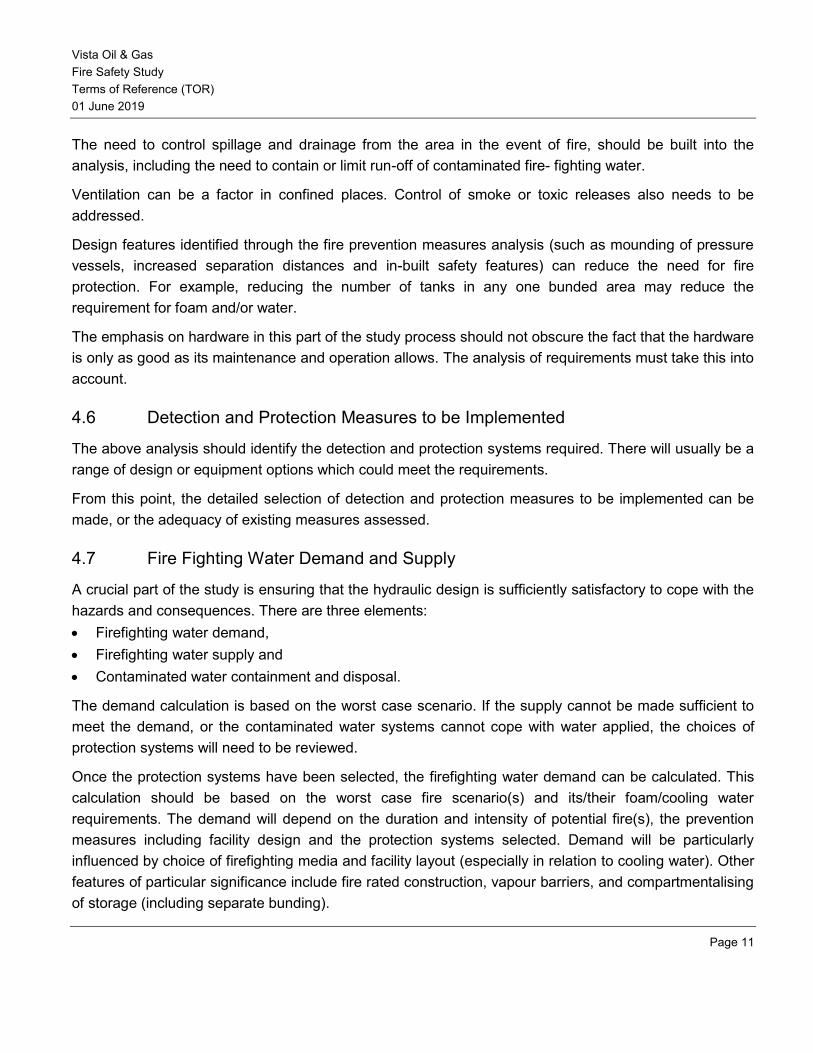
Vista Oil & Gas Fire Safety Study Terms of Reference (TOR) 01 June 2019
Page 11
The need to control spillage and drainage from the area in the event of fire, should be built into the analysis, including the need to contain or limit run-off of contaminated fire- fighting water.
Ventilation can be a factor in confined places. Control of smoke or toxic releases also needs to be addressed.
Design features identified through the fire prevention measures analysis (such as mounding of pressure vessels, increased separation distances and in-built safety features) can reduce the need for fire protection. For example, reducing the number of tanks in any one bunded area may reduce the requirement for foam and/or water.
The emphasis on hardware in this part of the study process should not obscure the fact that the hardware is only as good as its maintenance and operation allows. The analysis of requirements must take this into account.
4.6 Detection and Protection Measures to be Implemented
The above analysis should identify the detection and protection systems required. There will usually be a range of design or equipment options which could meet the requirements.
From this point, the detailed selection of detection and protection measures to be implemented can be made, or the adequacy of existing measures assessed.
4.7 Fire Fighting Water Demand and Supply
A crucial part of the study is ensuring that the hydraulic design is sufficiently satisfactory to cope with the hazards and consequences. There are three elements: • Firefighting water demand, • Firefighting water supply and • Contaminated water containment and disposal.
The demand calculation is based on the worst case scenario. If the supply cannot be made sufficient to meet the demand, or the contaminated water systems cannot cope with water applied, the choices of protection systems will need to be reviewed.
Once the protection systems have been selected, the firefighting water demand can be calculated. This calculation should be based on the worst case fire scenario(s) and its/their foam/cooling water requirements. The demand will depend on the duration and intensity of potential fire(s), the prevention measures including facility design and the protection systems selected. Demand will be particularly influenced by choice of firefighting media and facility layout (especially in relation to cooling water). Other features of particular significance include fire rated construction, vapour barriers, and compartmentalising of storage (including separate bunding).
Vista Oil & Gas Fire Safety Study Terms of Reference (TOR) 01 June 2019
Page 12
Analysis of supply should cover details of the fire water pumps. This would include the number of pumps and their configuration; power supply; pump details including capacity, type, pump curves, backup and so on. The calculations justifying the fire protection should show pressure and flows on operation of any and all of firefighting facilities in the area under review.
Where appropriate, the facility should be divided into fire areas and the water requirements calculated for each area. The design of the water supply system must be assessed against the calculated water demand.
The adequacy of the water supply available from town mains should be assessed based on written advice from the local water authority. Where the mains water supply is not adequate in terms of quantity or reliability, the need for static water supplies should be considered as well as the size and type of storage identified with drawings showing location of mains, size and street hydrants.
On-site water storage should be calculated to meet worst case demand. The minimum requirement is generally 90 minutes supply. Justification must be provided for the storage quantity adopted. Demand scenarios should include bund fires and cooling needs for adjacent tanks equipment and buildings.
The analysis needs to include careful consideration of the effect of potentially competing demands for reticulated and static water supply.
4.8 Containment of Contaminated Fire Fighting Water
The importance of the containment of contaminated water will depend on the nature of the materials held on site and where the site drains to. For example, if the site drains to a sensitive environmental area then special attention would be warranted.
Factors that need to be taken into account in the design of the retention system include control, drainage, storage and disposal.
The design of the contaminated water containment and disposal system should be based, where appropriate, on a probabilistic analysis. The analysis should account for not only the total containment of the calculated run-off of potentially significantly contaminated water from the worst case scenario fire but also the availability of the retention capacity as affected by rain events, testing, treatment and disposal arrangements. The possibility of soil and groundwater contamination should be considered in the analysis.
4.9 First Aid Fire Protection Arrangements and Equipment
In addition to fixed fire protection systems, provision for first aid fire protection equipment and operational arrangements must be considered.
Relevant matters to be covered would include:
Vista Oil & Gas Fire Safety Study Terms of Reference (TOR) 01 June 2019
Page 13
• Provision of portable fire extinguishers - size, type, medium, number, location, testing and maintenance;
• Provision of hose reels - number, location, type, testing and maintenance. Installed hose reels can remove the need for water type extinguishers;
• Provision of warning signs (including exit signs, placarding and first aid firefighting equipment use instruction signs), location, type, size;
• Site fire crews - formation, training, responsibilities and drills; • Training of operators/staff - knowledge of plant, materials, emergency action/shut down procedures;
and • Road vehicles measures - extinguishers, driver/operator instruction, placarding, vehicle maintenance.
The interaction of these matters with emergency planning should be carefully considered.
5 THE REPORT
The report should provide sufficient information on each element so that, either read alone or together with available and clearly cross-referenced documents, an assessment of the adequacy of fire prevention, detection, protection and fighting measures can be made. This section outlines the recommended format and content of the report.
A new page should be started for each section of the report.
5.1 Study Title Page
The study title should be clearly shown on both the cover and on a separate title sheet. The title should clearly and unambiguously identify the facility covered by the study: the type of operation, whether it is a proposed operation or an existing facility and its location. The title sheet should also show who prepared the study, on whose authority and the date.
5.2 Table of Contents
An easy to read table of contents with page numbers should be included at the beginning of the study. It should also include a list of figures and appendices.
5.3 Summary of Main Findings and Recommendations
The summary should briefly outline the nature of the proposed or existing facility, the scope of the report and the matters addressed. It should present in point form the main findings and, where appropriate, recommendations for action.
An implementation program agreed to by the proponent company or the owner or operator should be included. If any recommendations are not to be proceeded with reasons, they should be given.
Vista Oil & Gas Fire Safety Study Terms of Reference (TOR) 01 June 2019
Page 14
5.4 Glossary and Abbreviations
To ensure that the study can be understood, a glossary of any special terms, titles of personnel, names of parts of the plant and a list of abbreviations used should be included. For example:
Glossary and abbreviations
AFFF Aqueous Film Forming Foam BLEVE Boiling Liquid Expanding Vapor Explosion DCP Dry Chemical Powder DGC Dangerous Goods Classification DSA Drum Storage Area FH Fire Hydrant FHR Fire Hose Reel FMO Fire Maintenance Officer FPW Finished Products Warehouse FS Foam Store SWP Stored Water Pressure TFA Tank Farm Area UVCE Unconfined Vapor Cloud Explosion
5.5 Scope of Report
This section should give a brief description of the aims and purpose of the study and the reason for its preparation. For example, is it for an entirely new development, the modification of or extension to an existing development, or the establishment of adequacy of fire safety for an existing development? Is part or alI of the site addressed?
Reference should be made to any other relevant safety related studies previously carried out or under preparation.
5.6 Description of the Facility
This section should give an overview of the site, plant, buildings and substances used/stored. Design and construction standards must be addressed. Where this information is already available through an environmental impact statement (EIS), hazard analysis or other document, clear cross-reference to these documents and/or supply of copies as necessary would suffice.
The description should include: a) Details of the facility (general description) including brief process description where applicable; b) Site locational sketch (see Appendix 2); c) Site layout diagram (see Appendix 3);
Vista Oil & Gas Fire Safety Study Terms of Reference (TOR) 01 June 2019
Page 15
d) Building description including floor area limitations, fire resistance, means of egress, firefighting services and appliances, type of construction, and special provisions;
e) A generalized outline of the materials and quantities which are, or will be, stored or in process on site; f) A brief description of adjacent/surrounding land uses; and g) Number of people typically on the site and hours of operation.
5.7 Hazards Identified
A comprehensive list of materials which are or will be present on site should be provided. Information should include: a) Name of material — common, trade and IUPAC names. If mixtures, the relative proportions of each
component should be given; b) Class of material and type of hazard (for example, flammable, explosive, toxic, flammable toxic or
produces toxic combustion products). HAZCHEM UN number; c) Average and maximum quantities in storage and process; d) Physical state of substances (for example, pressurized, atmospheric, refrigerated, gas, liquid,
temperature); and e) Reference to process or storage area on site plan.
Where it is not possible or practicable to adequately describe a material within a tabular format, specification sheets and/or material safety data sheets should be provided. Reference to this additional information should be included in the table.
Hazardous incident scenarios identified in the study should be detailed, preferably in tabular format. In addition, an additional column containing comments relating to safeguards for each specific hazard identified should be included.
5.8 Consequences of Incidents
The estimated consequences of potential hazardous incidents, as developed in the study, should be detailed. Where applicable, diagrams showing worst case scenario heat flux distances, explosion overpressures and toxicity effects must be included. Such information should be time related where applicable. Consequence and risk contours used in the detailed quantitative risk analysis must be included.
The potential for fire propagation without fire protection measures should be detailed.
5.9 Fire Prevention Strategies/Measures
The full range of prevention strategies and measures identified in the study, as outlined in Section 4.4, should be described.
Vista Oil & Gas Fire Safety Study Terms of Reference (TOR) 01 June 2019
Page 16
Compliance with, or departures from, regulations and standards should be detailed. The justification for departures should be clearly set out.
Reference to an emergency response plan should be given if one has been prepared for the facility/site or is being written in conjunction with the fire safety study.
5.10 Details of Detection and Protection
The detection and protection systems selected should be detailed and justified in this section.
The full array of systems covering detection of flammable atmospheres, fire, smoke and heat, etc. together with the automatic and manually actuated suppression and protection systems should be covered where appropriate.
The analysis in the study, as outlined in sections 4.5 and 4.7, forms the basis of this section of the report.
Where applicable the detailing of detection and protection systems should be supported with drawings. Such drawings should be bound in to the report or enclosed in a securely attached pocket or pouch.
5.11 Detailed Drawings of Fire Services Layout
Detailed drawings showing the location and layout of various fire service components should be included to enable an assessment to be made of the compatibility of the system with the fire service. The drawings should cover access for emergency services and layout of all fire service pipework. Drawings of adequate scale to clearly indicate relevant details should show: • Pipe sizes; • Valves; • Fitting; • Materials; • Pumps; • Boosters; • Controls; • Water storage tanks; • Containment controls for used firefighting water; • Emergency vehicle access; • Connections to town mains; and • Hydrants.
A clear key should be provided. Drawings should be bound into the report document or enclosed in a securely attached pocket or pouch.
Vista Oil & Gas Fire Safety Study Terms of Reference (TOR) 01 June 2019
Page 17
5.12 Detailed Hydraulic Calculations for Fire-Fighting Water
The report should present a clear justification of the fire water system and decisions on static water storage supported by calculations and statements of assumptions. Both the demand for firefighting water and its supply need to be clearly addressed.
5.13 Arrangements for Containing Contaminated Fire Fighting Water
The arrangements for containing water which becomes contaminated during firefighting operations should be detailed. As outlined in section 4.8, the retention, treatment, testing and disposal arrangements chosen should be based on the nature and quantity of materials involved, the hydraulic calculations and the effect of rain events. The section should present both the assumptions and calculations on which arrangements are based, and also a justification of design and operational arrangements.
5.14 First Aid Fire Protection
The equipment and arrangements for first aid fire protection should be detailed based on the analysis outlined in section 4.9.
The location of fire extinguishers, hose reels and so on should be clearly shown on the site plan or other drawings included in the report as applicable.
5.15 Codes and References
The various codes and references used in the design and operation of the facility should be listed, and any exceptions or departures from the standards detailed and justified. Where codes and standards are not generally available, copies should be attached to the study (for example, specific company standards or insurance requirements).
5.16 Appendices
To support the content of the document, the following should be included as appendices: • Firefighting system water pressure (including inspection and functional testing records) • inspection and functional testing records for firefighting pumps; • Building plans; (indicate fire rated walls, doors and escape routes) • Drainage systems drawings; • Existing and/or proposed firefighting equipment list and drawings; • Sprinkler/drencher system layouts; • CO2, flood systems layouts; • Proposed fire protection layouts; • Hydraulic calculations

Vista Oil & Gas Fire Safety Study Terms of Reference (TOR) 01 June 2019
Page 18
• Fire protection/fighting equipment. type, design and specifications; • Drawings referred to in text; and • Reference list
Vista Oil & Gas Fire Safety Study Terms of Reference (TOR) 01 June 2019
Page 19
REFERENCES
The reader is referred to the following sources for further information:
[1] T. Kletz, HAZOP and HAZAN - Identifying and Assessing Process Industry Hazards, 4th edition, New York: Taylor & Francis, 1999.
[2] S. Mannan, ed., Lees' Loss Prevention in the Process Industries: Hazard Identification,
Assessment and Control, 3rd edition, Burlington, MA: Elsevier, 2005.
[3] Guidelines for Hazard Evaluation Procedures, with Worked Examples, 2nd edition, CCPS, 1992.
SPCC - TERMS OF REFERENCE
Rev 0
01 June 2019
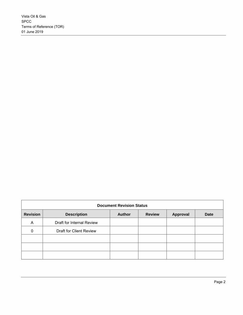
Vista Oil & Gas SPCC Terms of Reference (TOR) 01 June 2019
Page 2
Document Revision Status
Revision Description Author Review Approval Date
A Draft for Internal Review
0 Draft for Client Review
Vista Oil & Gas SPCC Terms of Reference (TOR) 01 June 2019
Page 3
Table of Contents
1 INTRODUCTION ...................................................................................................................... 4
1.1 Background .............................................................................................................................. 4
2 SCOPE .................................................................................................................................... 4
3 OBJECTIVE ............................................................................................................................. 4
4 THE SPILL RESPONSE PLAN ............................................................................................... 5
4.1 Overview .................................................................................................................................. 5
4.2 Facility Description ................................................................................................................... 5
4.3 Risk Assessment ...................................................................................................................... 5
4.4 Evaluation of Discharge Potential ............................................................................................. 5
4.5 Development of Strategy to Respond to Oil Spills .................................................................... 6
4.6 Spill Reporting .......................................................................................................................... 6
4.7 Potential Discharge Volumes and Direction of Flow ................................................................. 6
4.8 Containment and Diversionary Structures ................................................................................ 6
4.9 Inspections, Test and Records ................................................................................................. 7
4.10 Personnel, Training, and Discharge Prevention Procedures .................................................... 7
4.11 Tank Truck Loading/Unloading Areas Requirements ............................................................... 7
4.12 Facility Drainage ...................................................................................................................... 7
4.13 Bulk Storage Containers .......................................................................................................... 7
4.14 Discharge Response ................................................................................................................ 8
4.15 Spill Response Plan Update ..................................................................................................... 8
4.16 Codes and Standards .............................................................................................................. 8
4.17 Appendices .............................................................................................................................. 9
Vista Oil & Gas SPCC Terms of Reference (TOR) 01 June 2019
Page 4
1 INTRODUCTION
1.1 Background
The Spill Prevention, Control, and Countermeasure (SPCC) Plan helps prevent oil discharges from reaching surface and underground water resources; for example navigable waters, adjoining shorelines, and aquifers.
The SPCC Plan is used as a reference for oil storage information and water drainage testing records, as a tool to communicate practices on preventing and responding to discharges with employees, as a guide to facility inspections, and as a resource during emergency response.
2 SCOPE
The scope of the SPCC Plan covers the site plan of facility with respect to oil storage and handling, and development of a SPCC plan that describes equipment, procedures, workforce and training to prevent, control and provide adequate countermeasures to a discharge of oil.
3 OBJECTIVE
The objective of the SPCC Plan is to describe measures implemented by the client to prevent oil discharges from occurring, and to prepare the client to respond in a safe, effective, and timely manner to limit the spill size and mitigate the impacts of a discharge.
Vista Oil & Gas SPCC Terms of Reference (TOR) 01 June 2019
Page 5
4 THE SPILL RESPONSE PLAN
4.1 Overview
The approach used in this study should be based on industry standard methods given in the latest Environmental Protection Agency Spill Prevention, Control and Countermeasure (SPCC) regulations, and local regulations. Key aspects of the SPCC Plan are discussed in further detail in subsequent sections.
4.2 Facility Description
Relevant information about the facility includes the facility location, activities carried out at the facility, oil storage and other containers information. A Site Plan and Facility Diagram will show the location and layout of the facility. The Facility Diagram will show the location of oil containers, buildings, loading/unloading areas, critical spill control structures, and stormwater outfalls.
4.3 Risk Assessment
Once the scope of the facilities SPCC plan is developed, the next step is to conduct a risk assessment of their operations to identify: • All possible loss of primary containment (i.e.spill) sources • Potential discharge size of the spill • Spill secondary containment methods • Spill response methods • Time to initiate an active spill response • Cleanup activities The risk assessment should not be restricted to spills depending on the type or size and rather consider all the spills. Some of the type of spills to be considered include storage spills, facility piping, miscellaneous operations, etc. The contingency plans and adequate response levels to be developed will vary depending on the scope and risk assessment. The levels can be categorized to levels as below: • Level 1 – Minor local spills • Level 2 – Medium regional spills • Level 3 – Major national spills
4.4 Evaluation of Discharge Potential An evaluation of discharge potential includes a discussion about the distance to navigable waters, adjoining shorelines and any other potential water source contamination flow paths. In addition, an oil
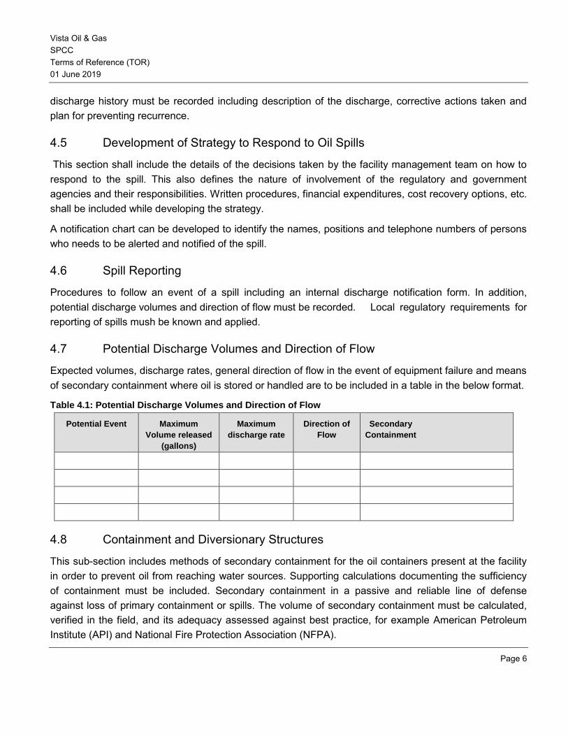
Vista Oil & Gas SPCC Terms of Reference (TOR) 01 June 2019
Page 6
discharge history must be recorded including description of the discharge, corrective actions taken and plan for preventing recurrence.
4.5 Development of Strategy to Respond to Oil Spills
This section shall include the details of the decisions taken by the facility management team on how to respond to the spill. This also defines the nature of involvement of the regulatory and government agencies and their responsibilities. Written procedures, financial expenditures, cost recovery options, etc. shall be included while developing the strategy.
A notification chart can be developed to identify the names, positions and telephone numbers of persons who needs to be alerted and notified of the spill.
4.6 Spill Reporting
Procedures to follow an event of a spill including an internal discharge notification form. In addition, potential discharge volumes and direction of flow must be recorded. Local regulatory requirements for reporting of spills mush be known and applied.
4.7 Potential Discharge Volumes and Direction of Flow
Expected volumes, discharge rates, general direction of flow in the event of equipment failure and means of secondary containment where oil is stored or handled are to be included in a table in the below format.
Table 4.1: Potential Discharge Volumes and Direction of Flow
Potential Event Maximum
Volume released
(gallons)
Maximum
discharge rate
Direction of
Flow
Secondary
Containment
4.8 Containment and Diversionary Structures
This sub-section includes methods of secondary containment for the oil containers present at the facility in order to prevent oil from reaching water sources. Supporting calculations documenting the sufficiency of containment must be included. Secondary containment in a passive and reliable line of defense against loss of primary containment or spills. The volume of secondary containment must be calculated, verified in the field, and its adequacy assessed against best practice, for example American Petroleum Institute (API) and National Fire Protection Association (NFPA).
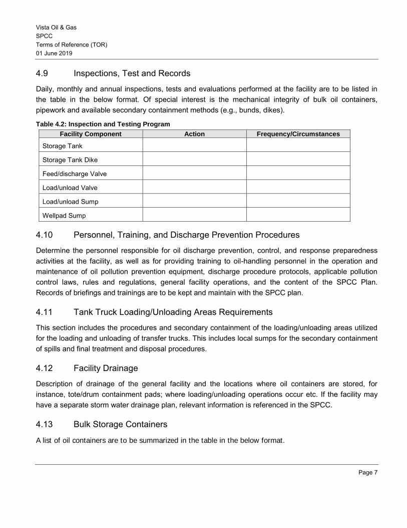
Vista Oil & Gas SPCC Terms of Reference (TOR) 01 June 2019
Page 7
4.9 Inspections, Test and Records
Daily, monthly and annual inspections, tests and evaluations performed at the facility are to be listed in the table in the below format. Of special interest is the mechanical integrity of bulk oil containers, pipework and available secondary containment methods (e.g., bunds, dikes).
Table 4.2: Inspection and Testing Program
Facility Component Action Frequency/Circumstances
Storage Tank
Storage Tank Dike
Feed/discharge Valve
Load/unload Valve
Load/unload Sump
Wellpad Sump
4.10 Personnel, Training, and Discharge Prevention Procedures
Determine the personnel responsible for oil discharge prevention, control, and response preparedness activities at the facility, as well as for providing training to oil-handling personnel in the operation and maintenance of oil pollution prevention equipment, discharge procedure protocols, applicable pollution control laws, rules and regulations, general facility operations, and the content of the SPCC Plan. Records of briefings and trainings are to be kept and maintain with the SPCC plan.
4.11 Tank Truck Loading/Unloading Areas Requirements
This section includes the procedures and secondary containment of the loading/unloading areas utilized for the loading and unloading of transfer trucks. This includes local sumps for the secondary containment of spills and final treatment and disposal procedures.
4.12 Facility Drainage
Description of drainage of the general facility and the locations where oil containers are stored, for instance, tote/drum containment pads; where loading/unloading operations occur etc. If the facility may have a separate storm water drainage plan, relevant information is referenced in the SPCC.
4.13 Bulk Storage Containers
A list of oil containers are to be summarized in the table in the below format.
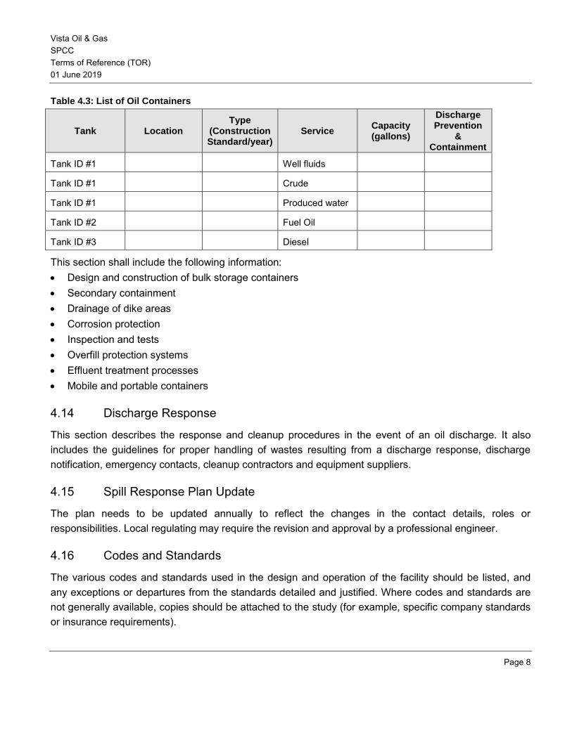
Vista Oil & Gas SPCC Terms of Reference (TOR) 01 June 2019
Page 8
Table 4.3: List of Oil Containers
Tank Location Type
(Construction Standard/year)
Service Capacity (gallons)
Discharge Prevention
& Containment
Tank ID #1 Well fluids
Tank ID #1 Crude
Tank ID #1 Produced water
Tank ID #2 Fuel Oil
Tank ID #3 Diesel
This section shall include the following information: • Design and construction of bulk storage containers • Secondary containment • Drainage of dike areas • Corrosion protection • Inspection and tests • Overfill protection systems • Effluent treatment processes • Mobile and portable containers
4.14 Discharge Response
This section describes the response and cleanup procedures in the event of an oil discharge. It also includes the guidelines for proper handling of wastes resulting from a discharge response, discharge notification, emergency contacts, cleanup contractors and equipment suppliers.
4.15 Spill Response Plan Update
The plan needs to be updated annually to reflect the changes in the contact details, roles or responsibilities. Local regulating may require the revision and approval by a professional engineer.
4.16 Codes and Standards
The various codes and standards used in the design and operation of the facility should be listed, and any exceptions or departures from the standards detailed and justified. Where codes and standards are not generally available, copies should be attached to the study (for example, specific company standards or insurance requirements).
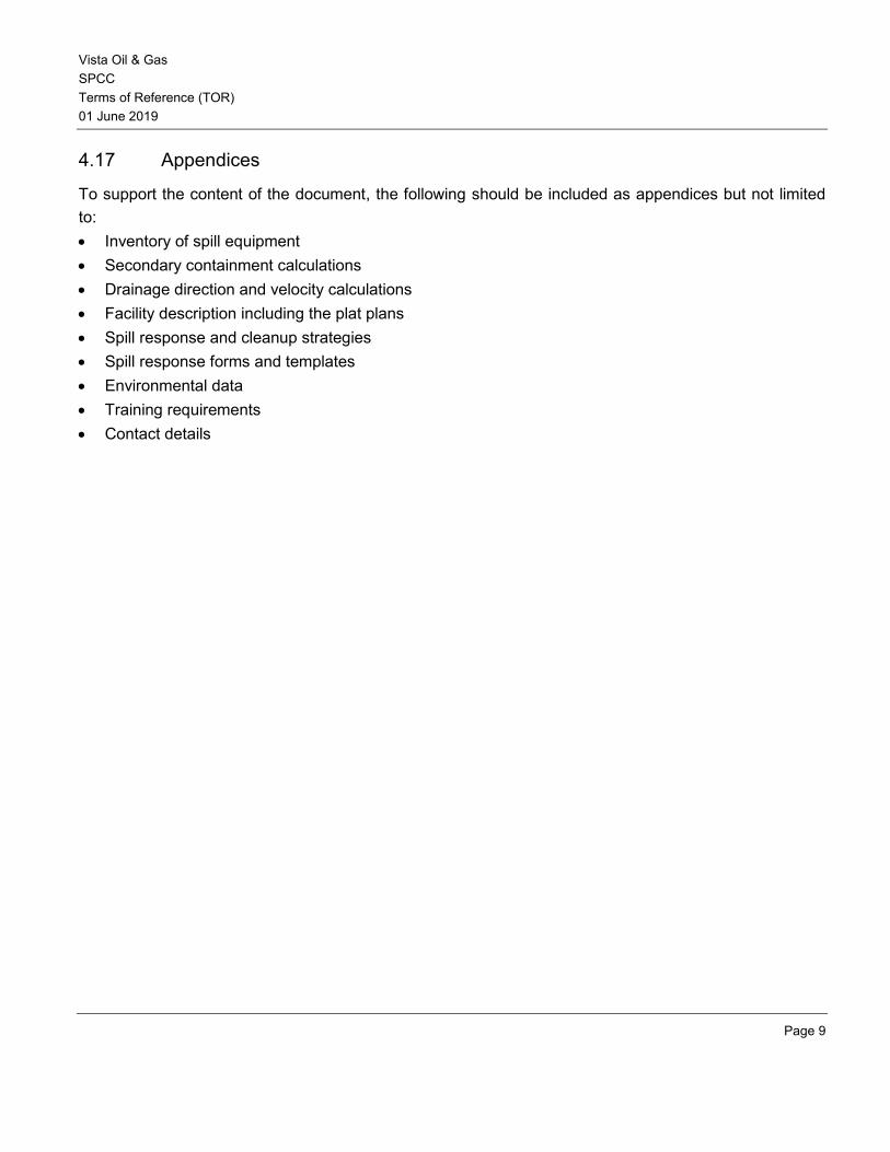
Vista Oil & Gas SPCC Terms of Reference (TOR) 01 June 2019
Page 9
4.17 Appendices
To support the content of the document, the following should be included as appendices but not limited to: • Inventory of spill equipment • Secondary containment calculations • Drainage direction and velocity calculations • Facility description including the plat plans • Spill response and cleanup strategies • Spill response forms and templates • Environmental data • Training requirements • Contact details

Vista Oil & Gas SPCC Terms of Reference (TOR) 01 June 2019
Page 10
REFERENCES
The reader is referred to the following sources for further information:
[1] ARPEL Guidelines for Oil Spill Management and Contingency Planning, Dec 1997.
[2] EPA Spill Prevention, Control, and Countermeasure (SPCC) Regulation, 40 CFR Part 112, A Facility Owner/Operator’s Guide to Oil Pollution Prevention.
EMEREGENCY RESPONSE PLAN - TERMS OF
REFERENCE
Rev 0
01 June 2019

Vista Oil & Gas Emergency Response Plan Terms of Reference (TOR) 01 June 2019
Page 2
Document Revision Status
Revision Description Author Review Approval Date
A Draft for Internal Review
0 Draft for Client Review

Vista Oil & Gas Emergency Response Plan Terms of Reference (TOR) 01 June 2019
Page 3
Table of Contents
1 INTRODUCTION ...................................................................................................................... 5
1.1 Purpose ................................................................................................................................... 5
1.2 Scope ....................................................................................................................................... 5
1.3 Objective .................................................................................................................................. 5
2 DESCRIPTION OF THE FACILITY .......................................................................................... 6
3 GENERAL EMERGENCY RESPONSE PRINCIPLES ............................................................. 7
3.1 General .................................................................................................................................... 7
3.2 Major Accident Events.............................................................................................................. 7
3.3 Emergency Levels .................................................................................................................... 7
3.3.1 Level 1 Incident ........................................................................................................................ 8
3.3.2 Level 2 Incident ........................................................................................................................ 8
3.3.3 Level 3 Incident ........................................................................................................................ 8
3.4 Emergency Response Organization ......................................................................................... 9
3.4.1 Incident Commander (IC) ......................................................................................................... 9
3.4.2 Safety Officer ........................................................................................................................... 9
3.4.3 Liaison Officer .......................................................................................................................... 9
3.4.4 Public Information Officer ....................................................................................................... 10
3.4.5 Operations Lead..................................................................................................................... 10
3.4.6 Planning Lead ........................................................................................................................ 10
3.4.7 Finance/Administration Lead .................................................................................................. 10
3.4.8 Logistics Lead ........................................................................................................................ 11
3.5 Unified Command System (UCS) ........................................................................................... 11
4 COMMUNICATION PROCESS .............................................................................................. 12
4.1 Emergency Communications.................................................................................................. 12
4.2 Emergency Contact Details .................................................................................................... 12
4.3 Action Plan ............................................................................................................................. 12
5 INCIDENT PLANNING ........................................................................................................... 13
5.1 Liaison with Agencies ............................................................................................................. 13
5.2 Training .................................................................................................................................. 13

Vista Oil & Gas Emergency Response Plan Terms of Reference (TOR) 01 June 2019
Page 4
5.3 Drills ....................................................................................................................................... 13
6 POST INCIDENT ACTIVITIES ............................................................................................... 14
6.1 Overview ................................................................................................................................ 14
7 MANAGEMENT REVIEW ...................................................................................................... 15
7.1 Overview ................................................................................................................................ 15
7.2 Review Process ..................................................................................................................... 15
8 CODES AND STANDARDS .................................................................................................. 16
9 REFERENCES ...................................................................................................................... 17
10 APPENDICES ........................................................................................................................ 18
Vista Oil & Gas Emergency Response Plan Terms of Reference (TOR) 01 June 2019
Page 5
1 INTRODUCTION
1.1 Purpose
The purpose of the emergency response plan (ERP) is to describe how Vista Oil & Gas will manage an emergency situation during drilling and operations of the wells and associated production facilities or impacting the operations, thereby minimizing damage to the people and the environment. This plan provides guidance to respond to emergencies arising due to major fire, explosion, major spill, or natural calamities, operational emergencies like blowout, in an appropriate and safe manner. Furthermore, it provides key roles and responsibilities, necessary protective and corrective measures, outlines communication processes and a description of what to report, when to report and how to report an emergency.
1.2 Scope
This document provides requirements for the development, testing, and documentation of an emergency response plan.
1.3 Objective
The objective of this document is to outline a method to develop an emergency response plan to:
• Ensure the safety of all personnel;
• Protect the environment;
• Minimize the impact of damage to equipment and assets;
• Provide managerial and technical support in the event of an emergency; and
• Minimize disruption to the workplace and neighboring activities.
Such study is required as part of the overall safety assessment of development and building proposals and also used to plan how to respond in the event of an emergency.
Vista Oil & Gas Emergency Response Plan Terms of Reference (TOR) 01 June 2019
Page 6
2 DESCRIPTION OF THE FACILITY
This section should give an overview of the site, plant, buildings and substances used/stored. Design and construction standards must be addressed. Where this information is already available through an environmental impact statement (EIS), hazard analysis or other document, clear cross-reference to these documents and/or supply of copies as necessary would suffice.
The description should include: a) Details of the facility (general description) including brief process description where applicable; b) Main occupation al and process hazards identified that can escalate into major accident events
resulting in consequences affective lives, environment or the capability to safety and lawfully operate the site or facility;
c) Site locational sketch; d) Site layout diagram; e) Building description including floor area limitations, fire resistance, means of egress, firefighting
services and appliances, type of construction, and special provisions; f) A generalized outline of the materials and quantities which are, or will be, stored or in process on site; g) A brief description of adjacent/surrounding land uses; and h) Number of people typically on the site and hours of operation.
Vista Oil & Gas Emergency Response Plan Terms of Reference (TOR) 01 June 2019
Page 7
3 GENERAL EMERGENCY RESPONSE PRINCIPLES
3.1 General
An emergency incident is defined as an occurrence that results in:
a) The death of or serious injury to a person;
b) Kidnap of a project person, including project personnel actively detained or taken hostage
c) A significant adverse effect on the environment;
d) An unintended fire or explosion;
e) Violence in the workplace involving a weapon or instance where authorities will be summoned.
f) Terroristic violence or sabotage with intent to harm personnel
g) Mob threat of impending violence, including violent protests
h) An unintended or uncontained release of hydrocarbons
An emergency is an unforeseen or imminent event that requires the following:
a) Prompt coordination of resources;
b) Special communications; and/or,
c) Heightened authority for employees, in order to protect the health, safety, and welfare of people first; and then to limit damage to property and to the environment.
3.2 Major Accident Events
One initial task in development of an ERP is to identify possible major hazardous emergency scenarios and describe with the most severe consequences and highest potential for escalation for each emergency. This will include the initiating events, its causes, consequences and its impact on public, environment or assets due to escalation of such events. These events will be identified and listed to establish adequate response in each case.
3.3 Emergency Levels
Once the hazardous scenarios are identified then the levels of response for emergency situations shall be determined in accordance with the:
• Actual outcome of an emergency incident/situation and evaluation of actual risk; and
• Potential outcome of the emergency incident/situation and evaluation of potential risk.
Vista Oil & Gas Emergency Response Plan Terms of Reference (TOR) 01 June 2019
Page 8
The activation and notification level of emergency response will depend upon the incident classification. Emergency incidents are classified on three levels according to the severity of the incident.
3.3.1 Level 1 Incident
A minor worksite incident or emergency which is contained by onsite personnel and resources. The incident presents a minimal risk to public health and/or the environment with containment and cleanup. Response to a level 1 incident would involve facility personnel only. Ongoing review of each incident would allow for escalation or de-escalation, as warranted. Level 1 incidents are:
• Work related personal injuries requiring days away from work;
• Damage to facilities with no impact on operations;
• Faults and errors of operation of powered equipment (mechanical, hydraulic or pneumatic).
3.3.2 Level 2 Incident
A serious worksite incident or emergency, which requires assistance from offsite personnel and resources, and external support to contain the situation. The incident presents a moderate risk to public health and/or the environment. Level 2 incidents involve:
• One or more fatalities occurring within the facility
• Damage to facilities with interruption of operations
• Oil spill and release of potentially dangerous substances affecting the environment (below the allowable limits)
3.3.3 Level 3 Incident
The major worksite incident or emergency, which requires assistance from offsite third parties to manage or contain the situation or a situation which effects or has strategic implications for the operating company. This incident presents immediate and extreme danger to life, property or environment. Level 3 incidents involve:
• One or more fatalities occurring outside the facility
• Damage to facilities with interruption of operations and personnel evacuation
• Oil spill and release of potentially dangerous substances affecting the environment (above the allowable limits)
Vista Oil & Gas Emergency Response Plan Terms of Reference (TOR) 01 June 2019
Page 9
3.4 Emergency Response Organization
In order to effectively respond to an emergency, the lines of communication and roles and responsibilities must be clearly understood. The emergency response team roles and responsibilities should be clearly and should be something similar to the one’s listed below.
3.4.1 Incident Commander (IC)
In charge of the organization’s on-scene response:
a) Maintain command until public agencies arrive and assume command or when relieved at start of next operational period.
b) Assess the situation.
c) Order warning of persons at risk or potentially at risk to take appropriate protective actions.
d) Notify or verify internal teams, departments, public agencies, regulators, contractors and suppliers have been notified.
e) Appoint others to incident command positions as needed.
f) Brief staff on current organization and activities; assign tasks; schedule planning meeting.
g) Determine the incident objectives and strategy; identify information needed or required by others; ensure planning/strategy meetings are held and attend as needed.
h) Coordinate activities with the emergency operations center (EOC); identify priorities and activities; provide impact assessment for business continuity, crisis communications and management.
i) Review requests for resources; confirm who has authority to approve procurement; approve all requests for resources as required.
j) Provide information to and coordinate with crisis communications or media relations team.
k) Terminate the response and demobilize resources when the situation has been stabilized. The IC has the ultimate authority in the event response.
3.4.2 Safety Officer
a) Support and monitor the organization’s on-scene response:
b) Identify and assess hazardous situations; prevent accidents.
c) Prepare safety plan; ensure messages are communicated.
d) Stop unsafe acts; correct unsafe conditions.
3.4.3 Liaison Officer
a) Point of contact with outside agencies and companies
b) Monitors operations to identify inter-organizational problems
Vista Oil & Gas Emergency Response Plan Terms of Reference (TOR) 01 June 2019
Page 10
3.4.4 Public Information Officer
a) Notify spokespersons.
b) Develop information for use in media briefings.
c) Obtain IC’s and management approval for all news releases.
d) Conduct periodic media briefings.
a) Arrange for tours, interviews and or briefings.
b) Monitor and forward useful information to the media.
c) Coordinate with business continuity and senior management teams.
d) Assemble information on alternative strategies and plans.
e) Assess current and potential impacts on people, property, and/or environment.
f) Compile and display incident status information.
3.4.5 Operations Lead
a) Manage all tactical operations during the incident.
b) Assist in the development of the operations portion of the Incident Action Plan.
c) Ensure safe tactical operations for all responders (in conjunction with any assigned Safety Officer).
d) Request additional resources to support tactical operations.
e) Expedite appropriate changes in the operations portion of the Incident Action Plan.
f) Maintain close communication with the Incident Commander.
3.4.6 Planning Lead
a) Conduct and facilitate planning meetings.
b) Supervise preparation of the Incident Action Plan.
c) Determine need for technical experts from within the company or outside as well as specialized resources to support the incident.
3.4.7 Finance/Administration Lead
a) Manages all financial aspects of the incident.
b) Provides financial and cost analysis information as requested.
c) Create accounts for claims and costs; coordinates with Logistics.
d) Tracks worker time and costs for materials and supplies.
e) Documents claims for damage, liability and injuries.
f) Notifies risk management/insurance to initiate claims reporting.
Vista Oil & Gas Emergency Response Plan Terms of Reference (TOR) 01 June 2019
Page 11
g) Provides incurred and forecasted costs at planning meetings.
h) Provides oversight of financial expenditures, new leases, contracts and assistance agreements to comply with corporate governance.
3.4.8 Logistics Lead
a) Provides resources to stabilize the incident and support personnel, systems and equipment:
b) Workspace or facilities for incident management staff;
c) Media briefing center;
d) Transportation;
e) Communications equipment; and,
f) Food, water, shelter and medical care.
g) Ensures Incident Command Post and other facilities have been established as needed.
h) Assesses communications needs and facilitates communications between teams/personnel/agencies.
i) Attends planning meetings; provides input to Incident Action Plan.
j) Provides updates on resources (availability, response time, deployment).
k) Estimates and procures resources for the next operational period.
3.5 Unified Command System (UCS)
The Unified Command System (UCS) is the structure and method in which all efforts to respond to a major event shall be unified under a single Incident Command System. The UCS shall include different agencies and organizations working tighter under the same goal and objectives. The primary entities include:
• Federal On-Scene Coordinator
• State On-Scene Coordinator
• Company Incident Commander
These three persons share decision-making authority within the Incident Command System and are each responsible for coordinating other Federal, State, and Company personnel to form an effective and integrated Emergency Management Team.
Vista Oil & Gas Emergency Response Plan Terms of Reference (TOR) 01 June 2019
Page 12
4 COMMUNICATION PROCESS
4.1 Emergency Communications Communication is the critical part of the emergency response. Emergency personnel need to be appropriately informed during a serious incident to enable effective emergency support. Communicating the proper details during an emergency are critical to quickly respond to the emergency appropriately. The response team may use a number of tools to help in decision making. Some of the tools include information boards, log sheets, etc.
The project specific emergency notification flowchart details the communication lines for ensuring a suitable response and provision of support for major incidents.
4.2 Emergency Contact Details
An emergency contact list shall be maintained at the facility listing the information as shown below:
Contact Information
Name Position Telephone Facsimile Email
4.3 Action Plan The action plan shall include details such as first aid treatment, emergency medical evacuation, admission and care at the nearest hospital, contracts with third party emergency response services, liaison with agencies and local authorities, etc.
Vista Oil & Gas Emergency Response Plan Terms of Reference (TOR) 01 June 2019
Page 13
5 INCIDENT PLANNING
5.1 Liaison with Agencies Liaison activities shall be made to appropriate public emergency response agencies having jurisdiction over sections of the pipeline. Contact shall be made with each agency at least once each calendar year. Liaison activities with public emergency response agencies will be one of the following:
• Meetings in person; • Group meetings; or • Mail out programs.
The purpose of these meetings is to provide an opportunity to talk directly with the public emergency response agencies about the location and characteristics of the pipeline under construction, and to review first responder pipeline emergency response protocols.
During these contacts it is important to share information about the operations and acquaint the officials with the facilities emergency plan. They should know the viability of Company's personnel, equipment, and materials for response to emergencies. The agencies should be provided with names and phone numbers of appropriate Company employees who can be contacted at any hour.
During the initial and subsequent visits, Company and agency personnel should plan how to engage in mutual assistance to minimize hazards to life and property. Consideration should be given to various situations including those where other emergency personnel, such as fire and police, may be able to respond more quickly than Company personnel. Police and fire department personnel should take action toward protection of the public by means of evacuation where needed, pending the arrival of Company personnel.
System information and maps should be shared for the area of fire and police agency’s jurisdictions. Responder agencies should be supplied with Material Safety Data Sheets.
5.2 Training All employees operating at this facility shall be trained to ensure readiness for emergencies. The investigation and analysis of exercises and emergency incidents shall help to ensure that all lessons learned will be communicated to facilitate improvements to the system.
5.3 Drills Developing and documenting emergency drills help to verify the contact lists are accurate, to train personal how to respond to an emergency and the action plans.
Vista Oil & Gas Emergency Response Plan Terms of Reference (TOR) 01 June 2019
Page 14
6 POST INCIDENT ACTIVITIES
6.1 Overview After the incident has been declared complete by the IC, a proper demobilization process shall be developed to ensure that all the equipment is moved from the location of the event in a safe manner. The incident needs to be documented and an investigation needs to be performed to prevent reoccurrence. The framework for incident investigation depends upon the actual or potential severity of the incident. In all cases an incident should be reported within 12 hours of occurring with Notice of Incident (NOI). The company’s Oil & Gas risk matrix may be utilized to determine the investigation response level.
Vista Oil & Gas Emergency Response Plan Terms of Reference (TOR) 01 June 2019
Page 15
7 MANAGEMENT REVIEW
7.1 Overview
The ERP is an integral element of the overall safety management system, which ensures that the operations are safe for employees, contractors, and the general public. In that sense, the plan shall follow the principals of continual improvement to ensure that the plan is always updated and adequate for the risk.
7.2 Review Process
The review process shall indicate the timely review of the plan for completeness and updated information. At a minimum, this review shall ensure that the following information is adequate:
• Substantial threat to the facility • Emergency scenarios • Notification information (e.g. agencies, phone, etc.) • Incident Command System and Unified Command System • Information of the response organizations to be contracted (e.g. competency, capabilities, contact
information, response time, etc.) • Action plan for each scenario • Planning activities • Other relevant information
Additionally, the ERP shall be reviewed prior to initiation of any potential modifications to the operations to address the new changes and submit the document to the respective agencies for review.
Vista Oil & Gas Emergency Response Plan Terms of Reference (TOR) 01 June 2019
Page 16
8 CODES AND STANDARDS
The various codes and standards used in the design and operation of the facility should be listed, and any exceptions or departures from the standards detailed and justified. Where codes and standards are not generally available, copies should be attached to the study (for example, specific company standards or insurance requirements).

Vista Oil & Gas Emergency Response Plan Terms of Reference (TOR) 01 June 2019
Page 17
9 REFERENCES
The reader is referred to the following sources for further information:
[1] 30CFR§250.1930, Code of Federal Regulations, What must be included in my SEMS program for
SWA?
[2] ARPEL Guidelines for Oil Spill Management and Contingency Plan, Dec 1997.
Vista Oil & Gas Emergency Response Plan Terms of Reference (TOR) 01 June 2019
Page 18
10 APPENDICES
To support the content of the document, the following should be included as appendices: • Facility description including the plot plans • Training requirements • Organizational structure • Any forms or templates • Training requirements • Reference list
OCCUPATIONAL HEALTH AND SAFETY MANAGEMENT PLAN (OHS)
www.erm.com Version: 1.0 Project No.: 0510093 Client: Vista Oil & Gas 5 June 2018 C:\Users\ext_fcristof\Desktop\Mid Co\OPIC\ERM\Docs to deliver\10.7 - OHS_VF_Draft01.docx
Occupational Health and Safety Management Plan (OHS) Document subtitle
5 June 2018
Project No.: 0510093
@
OCCUPATIONAL HEALTH AND SAFETY MANAGEMENT PLAN (OHS)
www.erm.com Version: 1.0 Project No.: 0510093 Client: Vista Oil & Gas 5 June 2018 C:\Users\ext_fcristof\Desktop\Mid Co\OPIC\ERM\Docs to deliver\10.7 - OHS_VF_Draft01.docx
Document details The details entered below are automatically shown on the cover and the main page footer. PLEASE NOTE: This table must NOT be removed from this document.
Document title Occupational Health and Safety Management Plan (OHS)
Document subtitle Document subtitle
Project No. 0510093
Date 5 June 2018
Version 1.0
Author Erick Chang
Client Name Vista Oil & Gas
OCCUPATIONAL HEALTH AND SAFETY MANAGEMENT PLAN (OHS)
www.erm.com Version: 1.0 Project No.: 0510093 Client: Vista Oil & Gas 5 June 2018 C:\Users\ext_fcristof\Desktop\Mid Co\OPIC\ERM\Docs to deliver\10.7 - OHS_VF_Draft01.docx
Document history
ERM approval to issue
Version Revision Author Reviewed by Name Date Comments
Draft 00 Erick Chang Andrea Fernandez
Alfrido Wagner
04/06/2019 Borrador a Vista
Draft 01 Erick Chang Andrea Fernandez
Alfrido Wagner
05/06/2019 Borrador a OPIC
www.erm.com Version: 1.0 Project No.: 0510093 Client: Vista Oil & Gas 5 June 2018 Page i
OCCUPATIONAL HEALTH AND SAFETY MANAGEMENT PLAN (OHS) Document subtitle
CONTENTS
1. INTRODUCTION .......................................................................................................................... 3 1.1 Background .................................................................................................................................... 3 1.2 Scope ............................................................................................................................................ 3 1.3 Objectives ...................................................................................................................................... 3
2. OHS LEGISLATION AND STANDARDS .................................................................................... 4 2.1 Legislation...................................................................................................................................... 4 2.2 Standards ...................................................................................................................................... 6
3. VISTA OHS GOALS ................................................................................................................... 11 3.1 Overall Goals ............................................................................................................................... 11 3.2 Key Performance Indicators and Targets .................................................................................... 11
4. ORGANIZATION AND RESPONSIBILITIES ............................................................................. 13 4.1 General ........................................................................................................................................ 13 4.2 Contractor Responsibilities .......................................................................................................... 19
5. PROJECT SAFETY PLANNING ................................................................................................ 20 5.1 Hazard Identification and Risk Management ............................................................................... 20 5.2 Risk Acceptance Criteria.............................................................................................................. 21 5.3 Hazard Register ........................................................................................................................... 21 5.4 Permit to Work System ................................................................................................................ 21 5.5 Job Hazard Analysis .................................................................................................................... 21 5.6 Workplace Inspections ................................................................................................................. 21 5.7 Safety Equipment ........................................................................................................................ 22 5.8 Personal Protective Equipment .................................................................................................... 22 5.9 Occupational Health Monitoring ................................................................................................... 22 5.10 Health and Safety Meetings ......................................................................................................... 22 5.11 Health and Safety Promotion, Awareness and Orientation .......................................................... 23 5.12 Notice Boards .............................................................................................................................. 23
6. IMPLEMENTATION .................................................................................................................... 24 6.1 General ........................................................................................................................................ 24
6.1.1 Engineering ................................................................................................................. 24 6.1.2 Design ......................................................................................................................... 24 6.1.3 Construction ................................................................................................................ 25 6.1.4 Operation .................................................................................................................... 25 6.1.5 Abandonment.............................................................................................................. 25
6.2 Management of Change .............................................................................................................. 26 6.3 Purchasing and Control of Materials and Services ...................................................................... 26 6.4 Employee Selection, Competency and Training .......................................................................... 26
6.4.1 General ....................................................................................................................... 26 6.4.2 Project Induction Training ........................................................................................... 26 6.4.3 Operator Training ........................................................................................................ 26
6.5 Emergency Response Preparedness .......................................................................................... 26 6.5.1 Emergency Response Plan ........................................................................................ 26 6.5.2 Emergency Response Training ................................................................................... 27
7. MONITORING, AUDIT AND REVIEW ......................................................................................... 1 7.1 Incident/Hazard Reporting and Investigation ................................................................................. 1 7.2 Audits ............................................................................................................................................. 1 7.3 Reviews ......................................................................................................................................... 1

www.erm.com Version: 1.0 Project No.: 0510093 Client: Vista Oil & Gas 5 June 2018 Page ii
OCCUPATIONAL HEALTH AND SAFETY MANAGEMENT PLAN (OHS) Document subtitle
List of Tables Table 1: HSE Legislation ......................................................................................................................... 4 Table 2: VISTA Safety Performance Indicators and Targets ................................................................ 11 Table 3: Project Safety Responsibilities ................................................................................................ 16
List of Figures Figure 1: VISTATeam Organization .............................................................................................. 14 Figure 2: VISTA HSE Organization ............................................................................................... 15
www.erm.com Version: 1.0 Project No.: 0510093 Client: Vista Oil & Gas 5 June 2018 Page iii
OCCUPATIONAL HEALTH AND SAFETY MANAGEMENT PLAN (OHS) Document subtitle
1. INTRODUCTION
1.1 Background This document presents the Occupational Health and Safety Management Plan (OHS), which is applied to the construction, operation and abandonment activities of the VISTA facilities. Describe how VISTA activities will achieve corporate security policies and standards, and establish key responsibilities for VISTA staff.
1.2 Scope This OHS plan covers design, modification, construction, commissioning, operation and abandonment activities for VISTA. It is complemented by VISTA Risk Management Plan.
1.3 Objectives The objectives of the OHS are to:
• Define and communicate the VISTA health and safety policies, objectives, expectations and requirements;
• Assist the staff to deliver products and services that meet VISTA’s safety goals;
• Define the criteria against which health and safety performance will be judged;
• Describe the areas of health and safety responsibilities for the VISTA staff and Contractors;
• Describe the VISTA health and safety management practices that ensure safety activities are organized, managed and reported in a systematic and consistent manner; and
• Provide a safe and healthy working environment for the company’s employees, Contractors and others affected by its activities.
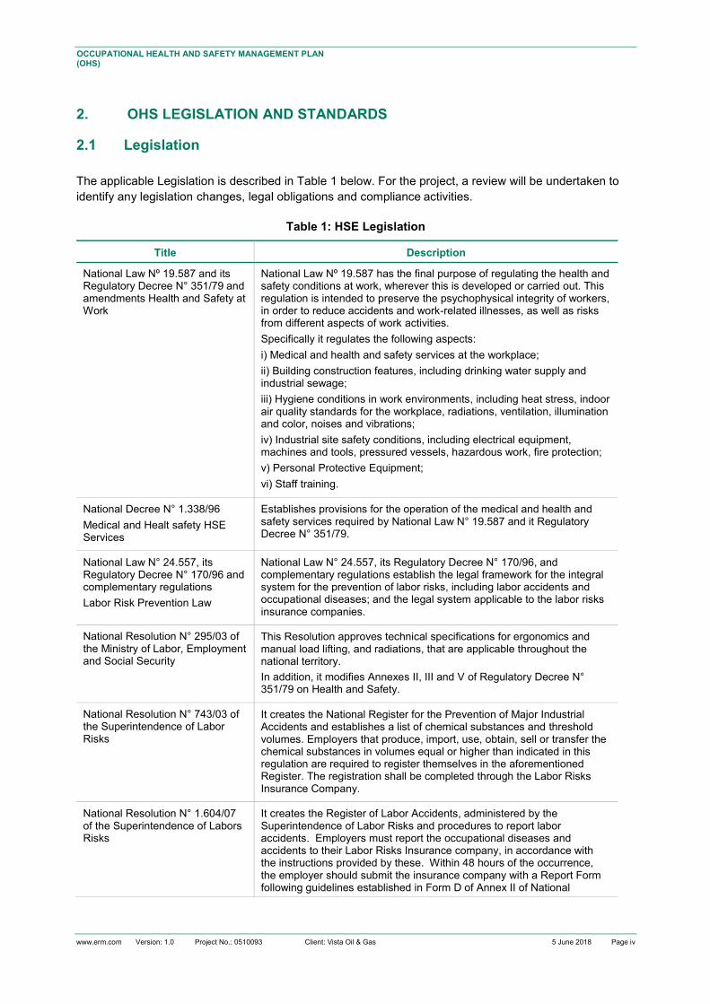
www.erm.com Version: 1.0 Project No.: 0510093 Client: Vista Oil & Gas 5 June 2018 Page iv
OCCUPATIONAL HEALTH AND SAFETY MANAGEMENT PLAN (OHS) Document subtitle
2. OHS LEGISLATION AND STANDARDS
2.1 Legislation The applicable Legislation is described in Table 1 below. For the project, a review will be undertaken to identify any legislation changes, legal obligations and compliance activities.
Table 1: HSE Legislation
Title Description
National Law Nº 19.587 and its Regulatory Decree N° 351/79 and amendments Health and Safety at Work
National Law Nº 19.587 has the final purpose of regulating the health and safety conditions at work, wherever this is developed or carried out. This regulation is intended to preserve the psychophysical integrity of workers, in order to reduce accidents and work-related illnesses, as well as risks from different aspects of work activities. Specifically it regulates the following aspects: i) Medical and health and safety services at the workplace; ii) Building construction features, including drinking water supply and industrial sewage; iii) Hygiene conditions in work environments, including heat stress, indoor air quality standards for the workplace, radiations, ventilation, illumination and color, noises and vibrations; iv) Industrial site safety conditions, including electrical equipment, machines and tools, pressured vessels, hazardous work, fire protection; v) Personal Protective Equipment; vi) Staff training.
National Decree N° 1.338/96 Medical and Healt safety HSE Services
Establishes provisions for the operation of the medical and health and safety services required by National Law N° 19.587 and it Regulatory Decree N° 351/79.
National Law N° 24.557, its Regulatory Decree N° 170/96 and complementary regulations Labor Risk Prevention Law
National Law N° 24.557, its Regulatory Decree N° 170/96, and complementary regulations establish the legal framework for the integral system for the prevention of labor risks, including labor accidents and occupational diseases; and the legal system applicable to the labor risks insurance companies.
National Resolution N° 295/03 of the Ministry of Labor, Employment and Social Security
This Resolution approves technical specifications for ergonomics and manual load lifting, and radiations, that are applicable throughout the national territory. In addition, it modifies Annexes II, III and V of Regulatory Decree N° 351/79 on Health and Safety.
National Resolution N° 743/03 of the Superintendence of Labor Risks
It creates the National Register for the Prevention of Major Industrial Accidents and establishes a list of chemical substances and threshold volumes. Employers that produce, import, use, obtain, sell or transfer the chemical substances in volumes equal or higher than indicated in this regulation are required to register themselves in the aforementioned Register. The registration shall be completed through the Labor Risks Insurance Company.
National Resolution N° 1.604/07 of the Superintendence of Labors Risks
It creates the Register of Labor Accidents, administered by the Superintendence of Labor Risks and procedures to report labor accidents. Employers must report the occupational diseases and accidents to their Labor Risks Insurance company, in accordance with the instructions provided by these. Within 48 hours of the occurrence, the employer should submit the insurance company with a Report Form following guidelines established in Form D of Annex II of National

www.erm.com Version: 1.0 Project No.: 0510093 Client: Vista Oil & Gas 5 June 2018 Page v
OCCUPATIONAL HEALTH AND SAFETY MANAGEMENT PLAN (OHS) Document subtitle
Title Description Resolution N° 1.604/07. The employer should provide the worker with a copy of the report submitted to the insurance company.
National Resolution N° 37/10 of the Superintendence of Labors Risks
Establishes the medical examinations included in the labor risks system, which comprise: 1. Pre-occupational. 2. Periodical. 3. Prior to the transference to another activity. 4. Following an extended absence. 5. Prior to ending the employment relationship. Pre-occupational examinations are mandatory. The Labor Risks Insurance company will determine the need for and frequency of periodical examinations. The results of the medical examinations should be kept in the personal file of each employee.
National Resolution N° 299/11 of the Superintendence of Labors Risks
Establishes that personal protective equipment provided to workers shall be certified by duly recognized organisms according to National Resolution N° 896/99 of the Secretariat of Industry, Commerce and Mining. It also creates the form “Working Clothing and Personal Protective Equipment Delivery Record” of mandatory use by employers. A form shall be completed for each worker in which the delivery of all working clothing and personal protective equipment shall be registered.
National Resolution Nº 905/15 of the Superintendence of Labors Risks
Establishes the functions of the H&S and Medical Service professionals, in compliance with Decree N° 1.338/96, in which are included the following: a) Verify the compliance of the H&S regulations by identifying the hazards and assessing the risks that could affect the employee´s health, and developing effective preventive measures. b) Verify and register the actions performed by the Labor Risks Insurance Company (ART), in which are included: Medical examinations, H&S compliance inspections, H&S benefits, etc. c) Conduct periodically visits on the working stations with the frequency depending on the risks assessments, the size of the company, and to verify compliance with any potential plan developed by the SRT (Superintendence of Labor Risks).
National Resolution No. 84/2012 of the Superintendence of Labors Risks
Establishes that annual monitoring must be conducted to verify if lighting is in compliance with the requirements and the lighting levels established in Annex IV of National Decree No. 351/79. It also requires to comply with guidelines established in the Protocol for Workplace Lighting Monitoring approved by this Resolution. Corrective measures must be implemented if light levels are detected to be below minimum levels for working stations.
National Resolution No. 85/2012 of the Superintendence of Labors Risks
Comply with guidelines established in the Protocol for Workplace Noise Monitoring approved by this Resolution. Workplace noise monitoring results shall be valid for a term of twelve (12) months (i.e. monitoring is required at least every 12 months).
Resolution No. 886/2015 of the Ministry of Job, Labor and Social Security
Requires to conduct an ergonomic assessment of the activities performed on site, according to Protocol for Ergonomics Monitoring approved by this Resolution.

www.erm.com Version: 1.0 Project No.: 0510093 Client: Vista Oil & Gas 5 June 2018 Page vi
OCCUPATIONAL HEALTH AND SAFETY MANAGEMENT PLAN (OHS) Document subtitle
2.2 Standards The applicable standards and codes of practice are determined and described in various documents including:
▪ Basis of design documents;
▪ VISTA health, safety and environment (HSE) policies and procedures; and
▪ Argentinean legislation and regulations.
▪ World Bank Group Environmental, Health, and Safety Guidelines
▪ Environmental, Health, and Safety Guidelines for Onshore Oil and Gas Development
It is outside the scope of this Plan to provide a comprehensive list of applicable standards for VISTA.
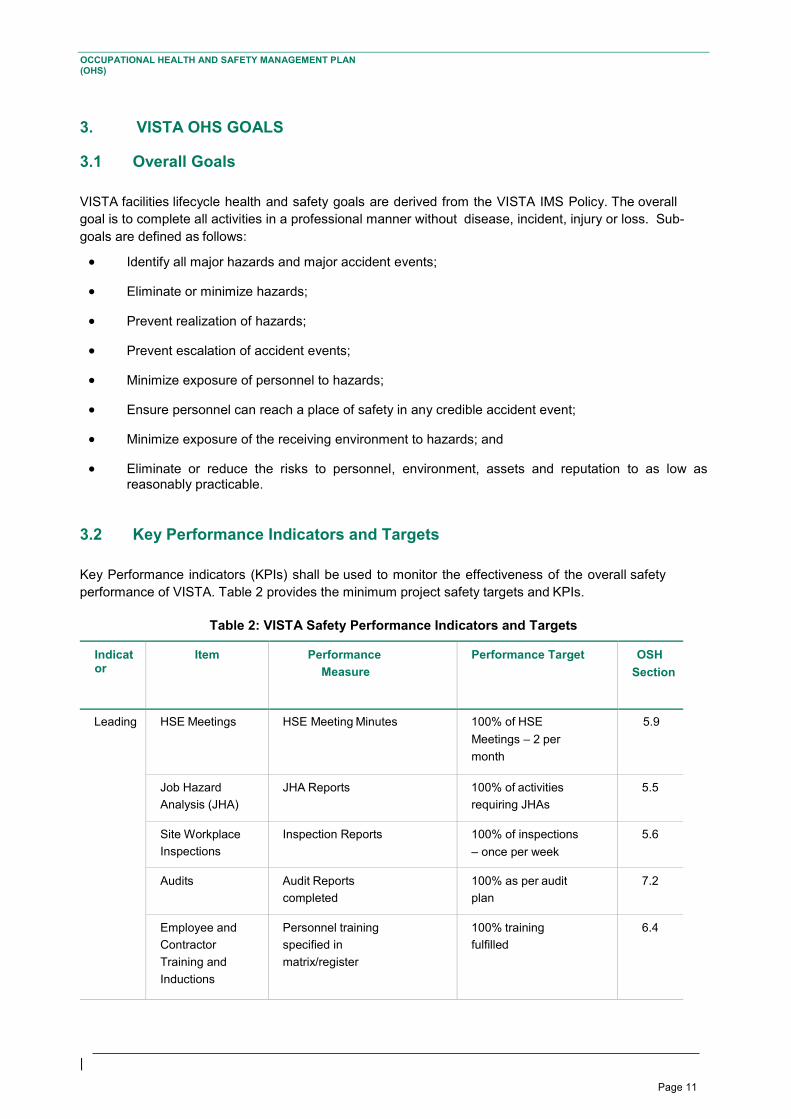
Page 11
|
OCCUPATIONAL HEALTH AND SAFETY MANAGEMENT PLAN (OHS) Document subtitle
3. VISTA OHS GOALS
3.1 Overall Goals VISTA facilities lifecycle health and safety goals are derived from the VISTA IMS Policy. The overall goal is to complete all activities in a professional manner without disease, incident, injury or loss. Sub-goals are defined as follows:
• Identify all major hazards and major accident events;
• Eliminate or minimize hazards;
• Prevent realization of hazards;
• Prevent escalation of accident events;
• Minimize exposure of personnel to hazards;
• Ensure personnel can reach a place of safety in any credible accident event;
• Minimize exposure of the receiving environment to hazards; and
• Eliminate or reduce the risks to personnel, environment, assets and reputation to as low as reasonably practicable.
3.2 Key Performance Indicators and Targets Key Performance indicators (KPIs) shall be used to monitor the effectiveness of the overall safety performance of VISTA. Table 2 provides the minimum project safety targets and KPIs.
Table 2: VISTA Safety Performance Indicators and Targets
Indicator
Item Performance Measure
Performance Target OSH Section
Leading HSE Meetings HSE Meeting Minutes 100% of HSE Meetings – 2 per month
5.9
Job Hazard Analysis (JHA)
JHA Reports 100% of activities requiring JHAs
5.5
Site Workplace Inspections
Inspection Reports 100% of inspections – once per week
5.6
Audits Audit Reports completed
100% as per audit plan
7.2
Employee and Contractor Training and Inductions
Personnel training specified in matrix/register
100% training fulfilled
6.4
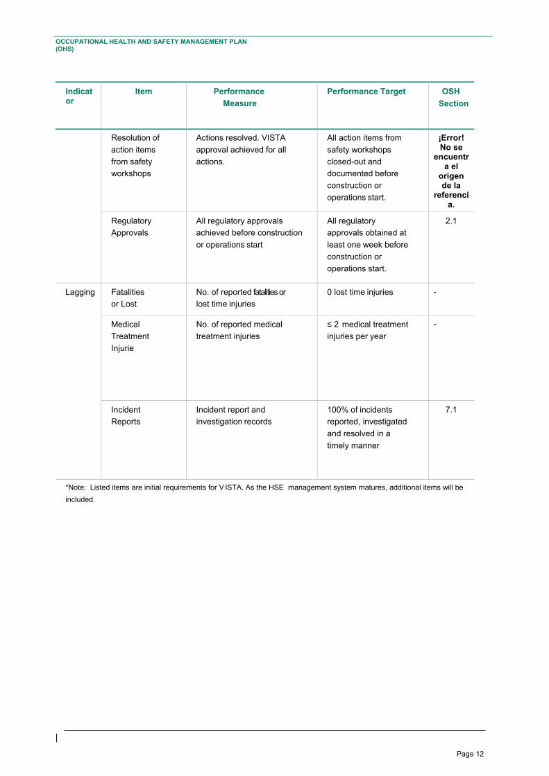
Page 12
|
OCCUPATIONAL HEALTH AND SAFETY MANAGEMENT PLAN (OHS) Document subtitle
Indicator
Item Performance Measure
Performance Target OSH Section
Resolution of action items from safety workshops
Actions resolved. VISTA approval achieved for all actions.
All action items from safety workshops closed-out and documented before construction or operations start.
¡Error! No se
encuentra el
origen de la
referencia.
Regulatory Approvals
All regulatory approvals achieved before construction or operations start
All regulatory approvals obtained at least one week before construction or operations start.
2.1
Lagging Fatalities or Lost Time Injuries
No. of reported fatalities or lost time injuries
0 lost time injuries -
Medical Treatment Injurie
No. of reported medical treatment injuries
≤ 2 medical treatment injuries per year
-
Incident Reports
Incident report and investigation records
100% of incidents reported, investigated and resolved in a timely manner
7.1
*Note: Listed items are initial requirements for V ISTA. As the HSE management system matures, additional items will be included.
Page 13
|
OCCUPATIONAL HEALTH AND SAFETY MANAGEMENT PLAN (OHS) Document subtitle
4. ORGANIZATION AND RESPONSIBILITIES
4.1 General The current general organization of VISTA is shown in figure 1. However, VISTA must ensure an ideal structure for the OHS program, which is suggested and includes the following personnel:
▪ Project Manager;
▪ Engineering personnel;
▪ Procurement personnel;
▪ HSE staff;
▪ Administrative support;
▪ Facility person in charge (Supervisor);
▪ Construction personnel;
▪ Commissioning personnel; Y
▪ Accounting staff.
The VISTA staff is responsible for the general management of the health and safety of facilities’ operations and projects. Supporting contractor organizations are responsible for health and safety within their areas of expertise and services. VISTA is responsible for the selection, vetting, and performance supervision of qualified contractors; to ensure equivalent OHS systems and programs are in place to protect both staff and contractor personnel.
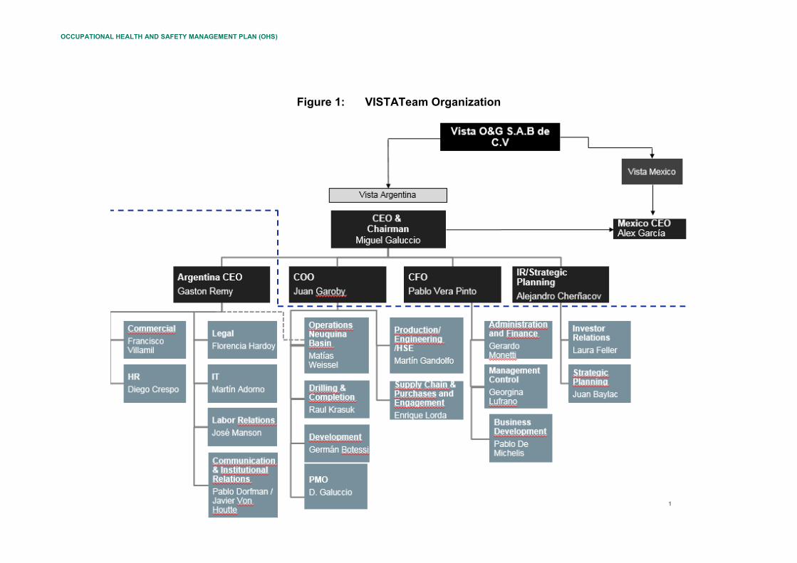
OCCUPATIONAL HEALTH AND SAFETY MANAGEMENT PLAN (OHS)
Figure 1: VISTATeam Organization
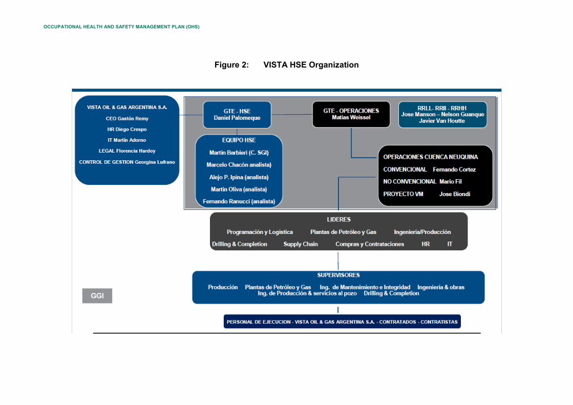
OCCUPATIONAL HEALTH AND SAFETY MANAGEMENT PLAN (OHS)
Figure 2: VISTA HSE Organization
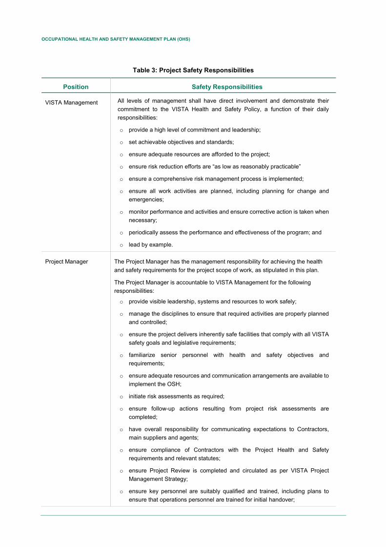
OCCUPATIONAL HEALTH AND SAFETY MANAGEMENT PLAN (OHS)
Table 3: Project Safety Responsibilities
Position Safety Responsibilities
VISTA Management All levels of management shall have direct involvement and demonstrate their commitment to the VISTA Health and Safety Policy, a function of their daily responsibilities:
o provide a high level of commitment and leadership;
o set achievable objectives and standards;
o ensure adequate resources are afforded to the project;
o ensure risk reduction efforts are “as low as reasonably practicable”
o ensure a comprehensive risk management process is implemented;
o ensure all work activities are planned, including planning for change and emergencies;
o monitor performance and activities and ensure corrective action is taken when necessary;
o periodically assess the performance and effectiveness of the program; and
o lead by example.
Project Manager The Project Manager has the management responsibility for achieving the health and safety requirements for the project scope of work, as stipulated in this plan.
The Project Manager is accountable to VISTA Management for the following responsibilities:
o provide visible leadership, systems and resources to work safely;
o manage the disciplines to ensure that required activities are properly planned and controlled;
o ensure the project delivers inherently safe facilities that comply with all VISTA safety goals and legislative requirements;
o familiarize senior personnel with health and safety objectives and requirements;
o ensure adequate resources and communication arrangements are available to implement the OSH;
o initiate risk assessments as required;
o ensure follow-up actions resulting from project risk assessments are completed;
o have overall responsibility for communicating expectations to Contractors, main suppliers and agents;
o ensure compliance of Contractors with the Project Health and Safety requirements and relevant statutes;
o ensure Project Review is completed and circulated as per VISTA Project Management Strategy;
o ensure key personnel are suitably qualified and trained, including plans to ensure that operations personnel are trained for initial handover;
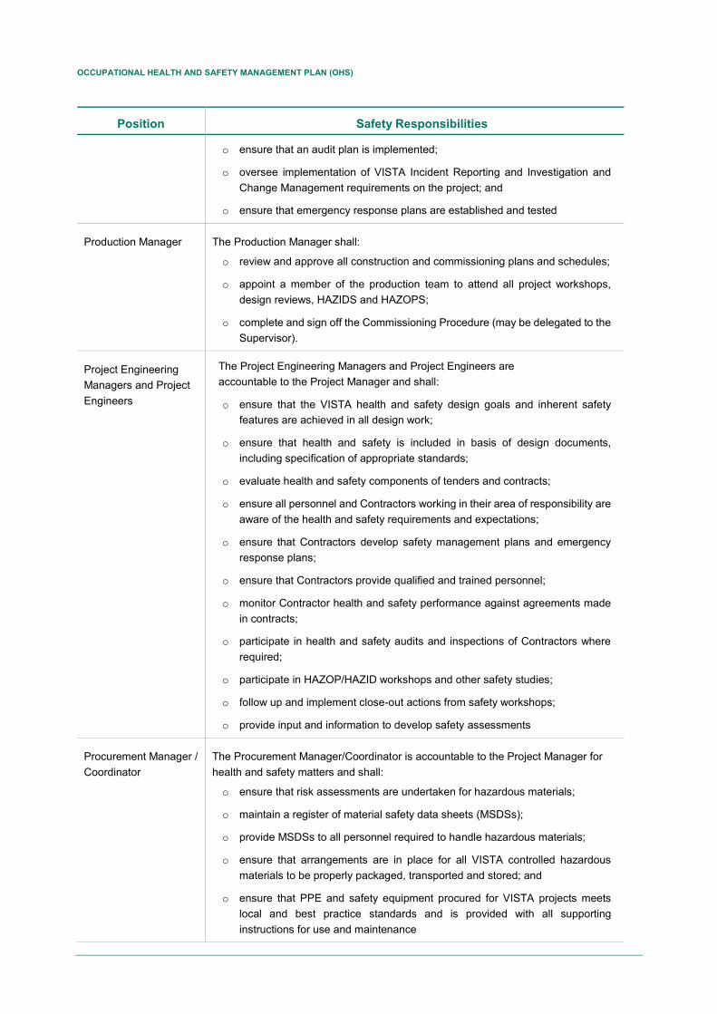
OCCUPATIONAL HEALTH AND SAFETY MANAGEMENT PLAN (OHS)
Position Safety Responsibilities
o ensure that an audit plan is implemented;
o oversee implementation of VISTA Incident Reporting and Investigation and Change Management requirements on the project; and
o ensure that emergency response plans are established and tested
Production Manager The Production Manager shall:
o review and approve all construction and commissioning plans and schedules;
o appoint a member of the production team to attend all project workshops, design reviews, HAZIDS and HAZOPS;
o complete and sign off the Commissioning Procedure (may be delegated to the Supervisor).
Project Engineering Managers and Project Engineers
The Project Engineering Managers and Project Engineers are accountable to the Project Manager and shall:
o ensure that the VISTA health and safety design goals and inherent safety features are achieved in all design work;
o ensure that health and safety is included in basis of design documents, including specification of appropriate standards;
o evaluate health and safety components of tenders and contracts;
o ensure all personnel and Contractors working in their area of responsibility are aware of the health and safety requirements and expectations;
o ensure that Contractors develop safety management plans and emergency response plans;
o ensure that Contractors provide qualified and trained personnel;
o monitor Contractor health and safety performance against agreements made in contracts;
o participate in health and safety audits and inspections of Contractors where required;
o participate in HAZOP/HAZID workshops and other safety studies;
o follow up and implement close-out actions from safety workshops;
o provide input and information to develop safety assessments
Procurement Manager / Coordinator
The Procurement Manager/Coordinator is accountable to the Project Manager for health and safety matters and shall:
o ensure that risk assessments are undertaken for hazardous materials;
o maintain a register of material safety data sheets (MSDSs);
o provide MSDSs to all personnel required to handle hazardous materials;
o ensure that arrangements are in place for all VISTA controlled hazardous materials to be properly packaged, transported and stored; and
o ensure that PPE and safety equipment procured for VISTA projects meets local and best practice standards and is provided with all supporting instructions for use and maintenance
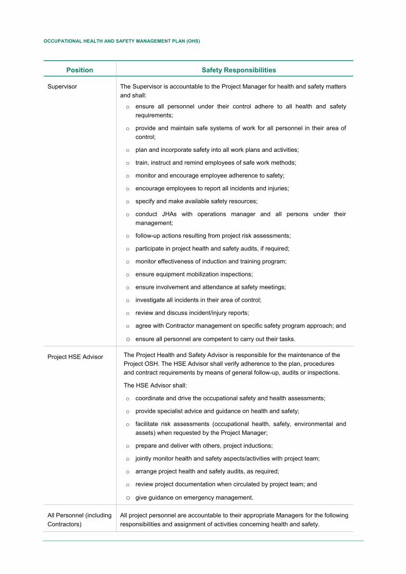
OCCUPATIONAL HEALTH AND SAFETY MANAGEMENT PLAN (OHS)
Position Safety Responsibilities
Supervisor The Supervisor is accountable to the Project Manager for health and safety matters and shall:
o ensure all personnel under their control adhere to all health and safety requirements;
o provide and maintain safe systems of work for all personnel in their area of control;
o plan and incorporate safety into all work plans and activities;
o train, instruct and remind employees of safe work methods;
o monitor and encourage employee adherence to safety;
o encourage employees to report all incidents and injuries;
o specify and make available safety resources;
o conduct JHAs with operations manager and all persons under their management;
o follow-up actions resulting from project risk assessments;
o participate in project health and safety audits, if required;
o monitor effectiveness of induction and training program;
o ensure equipment mobilization inspections;
o ensure involvement and attendance at safety meetings;
o investigate all incidents in their area of control;
o review and discuss incident/injury reports;
o agree with Contractor management on specific safety program approach; and
o ensure all personnel are competent to carry out their tasks.
Project HSE Advisor The Project Health and Safety Advisor is responsible for the maintenance of the Project OSH. The HSE Advisor shall verify adherence to the plan, procedures and contract requirements by means of general follow-up, audits or inspections.
The HSE Advisor shall:
o coordinate and drive the occupational safety and health assessments;
o provide specialist advice and guidance on health and safety;
o facilitate risk assessments (occupational health, safety, environmental and assets) when requested by the Project Manager;
o prepare and deliver with others, project inductions;
o jointly monitor health and safety aspects/activities with project team;
o arrange project health and safety audits, as required;
o review project documentation when circulated by project team; and
o give guidance on emergency management.
All Personnel (including Contractors)
All project personnel are accountable to their appropriate Managers for the following responsibilities and assignment of activities concerning health and safety.
OCCUPATIONAL HEALTH AND SAFETY MANAGEMENT PLAN (OHS)
Position Safety Responsibilities
Responsibilities:
o participate in and adhere to all safety instructions, procedures and safety activities including HAZID and HAZOP workshops when requested;
o report all incidents and hazards to management;
o wear PPE and clothing provided where applicable;
o advise fellow employees of hazardous situations;
o show consistent behaviors and attitudes to working safely;
o comply with statutory requirements;
o report hazardous conditions;
o provide suggestions to benefit health and safety matters on the project;
o report any near miss or property damage incident;
o participate in JHAs;
o participate in health and safety training and emergency response exercises;
o participate in workplace inspections; and
o Cooperate in audits.
4.2 Contractor Responsibilities Contractors will work in accordance with the VISTA Safety Management System, or alternatively VISTA will review and approve the Contractor HSE management system. Where required a Bridging Document or Interface Plan will be developed to align the Contractor’s HSE management system to VISTA’s management system.
The Contractor HSE management system review process will address all items covered by the OSH Management Plan, in particular:
▪ Hazard identification and risk management;
▪ Selection, training and competence of personnel;
▪ Permit to work;
▪ Management of change;
▪ Management arrangements for the control of goods and services;
▪ Identification, control and compliance of all project tools and equipment;
▪ Emergency response plan (ERP); and
▪ Specific Contractor standard operating procedures. Contractors are required to report all incidents and hazards.
Contractors are responsible for planning and ensuring that all necessary risk assessments have been executed, documented, and resulting actions closed-out prior to commencement of operations. Various HAZID and risk assessment workshops will be conducted for the project, and Contractors may be required to participate in these workshops.
OCCUPATIONAL HEALTH AND SAFETY MANAGEMENT PLAN (OHS)
Contractors that are approved to operate under their own HSE management system on VISTA work sites are required to prepare a Site Specific OSH Management Plan to cover their work scope. These must be submitted to the VISTA HSE advisor for review and approval. The plan shall outline the Contractor emergency response arrangements including interfaces.
5. PROJECT SAFETY PLANNING
5.1 Hazard Identification and Risk Management Matrixes for risk identification and risk management are used for Vista's HSE management. The hazards and risks identified from this technique must be managed through a comprehensive assessment of each hazard, assessing the risks, eliminating or reducing the risks for Vista and implementing control measures. To ensure the risk management process is effective, the hazards and risks identified shall be continually monitored and reviewed throughout the facility lifecycle.
Hazards may be identified and assessed by a variety of methods including: work place inspections, incident and investigation reports, HAZID/HAZOP workshops, permit to work applications, JHAs, safety and risk studies, management of change process and audits and reviews.
Hazard identification and risk assessment processes and their outcomes, as well as measures implemented towards risk reduction are typically documented in a Hazard Register (Refer to Section 5.3).
The hierarchy of controls refers to the systematic strategy used to control exposure to hazards. The controls are ranked in order of the effectiveness as follows:
▪ Elimination or minimization of the substance or hazard;
▪ Substitution of the process or chemical to one less hazardous;
▪ Engineering the process to eliminate or minimize the hazard;
o Reduce the likelihood of hazard events
o Reduce the consequences of hazard events
▪ Segregation in time or distance of the personnel from the hazard;
▪ Administration controls; including emergency response and recovery plans, and
▪ Personal protective equipment (PPE).
PPE shall always be considered as the last and least effective line of defence.
Risk assessment for VISTA facilities may include (Refer to VISTA Risk Management Plan):
▪ Qualitative analysis conducted in conjunction with hazard identification (HAZID) workshops;
▪ Qualitative analysis conducted in conjunction with process hazards analysis and hazard and operability (HAZOP) studies
▪ Bowtie studies to identify and assess major accident events
▪ Quantitative risk analysis (QRA)
▪ Well blowout risk assessments
▪ Pipeline risk assessments
OCCUPATIONAL HEALTH AND SAFETY MANAGEMENT PLAN (OHS)
5.2 Risk Acceptance Criteria The qualitative risk assessment criteria specified in the VISTA Risk Evaluation Matrix shall be used for all operations and maintenance activities during the course of the projects.
5.3 Hazard Register The HSE Advisor will maintain a Hazard Register and will be available to all VISTA staff. It will provide a record of the hazards identified during the design, construction, operation and abandonment of the project and the correct means to manage these hazards. It will incorporate a summary of the HAZID, HAZOP and other safety and risk assessments carried out during facility lifecycle.
The HSE Advisor shall regularly review the hazard register and shall ensure that appropriate controls have been introduced to either eliminate or reduce the risks to VISTA. The currency and effectiveness of the hazard registers shall be assessed during the audit process.
For field operations, the HSE Advisor will ensure that an appropriate person is made responsible for maintaining the project hazard register in the field. This will include adding new hazards that are identified in the field - e.g., during construction activities.
5.4 Permit to Work System The VISTA permit to work (PTW) system shall apply for all work in VISTA designated areas. The Facility Supervisor is responsible for ensuring the PTW procedure is implemented effectively. All personnel working on the location shall comply with the requirements and conditions of the PTW system. In certain circumstances, Contractors will be working under their own PTW system. The conditions and interfaces to the VISTA PTW system is to be defined in the bridging document, interface plan, or Site Specific Health and Safety Plan as appropriate.
5.5 Job Hazard Analysis Vista has some job hazard analysis (JHA) matrices, which apply to the VISTA operations and the Contractors, which be followed throughout the project to identify hazards and effective management methods. JHAs shall be conducted on all activities detailed in the project procedures, and on non- routine or potentially hazardous activities identified on the job. All JHAs will be carried out before each work, as well as the opening and closing of the work permit issued by the facility supervisor and received by the job performer (e.g. staff maintenance or contractor), within which they evaluate the risks associated with the activity, and the measures of mitigation for each of them. The final result will be discussed with all the people involved in the work, to ensure that the safety requirements and the JHA procedure are understood. The facility supervisor of VISTA or the Contractor, depending on the type of work, is responsible for ensuring that the JHA process is effectively implemented in the workplace. The Facility Supervisor will keep an archive of issued/executed work permits and their corresponding JHA.
5.6 Workplace Inspections Inspections in the workplace are done on a daily basis, depending on the work permits that have been opened. The supervision is carried out by VISTA personnel, and by the supervisors of the corresponding contractors. These supervisions are performed to:

OCCUPATIONAL HEALTH AND SAFETY MANAGEMENT PLAN (OHS)
▪ Identify potential hazards which emanate from or exist among all components of the workplace, and to initiate corrective action; and
▪ Ensure compliance with the project health and safety requirements, contract requirements and relevant legislation.
Project Management, HSE personnel and the Facility Supervisor shall at all times encourage personnel to identify and correct hazards as a part of their normal duties wherever possible and follow the Hazard/Incident Reporting and Investigation Procedure. Hazard/Incident Investigation Report Forms shall be made available to all operational personnel. Where correction of an identified hazard is outside the ability of the respective employee, or cannot be rectified immediately, the area affected by the hazard is to be made safe with barricades and warning signs and reported to the Supervisor immediately.
5.7 Safety Equipment Sufficient, approved safety equipment shall be provided by the Facility Supervisor, at all work sites associated with the project. All safety equipment shall comply with of H&S Standards.
5.8 Personal Protective Equipment The Supervisor is responsible for ensuring that adequate, fit for purpose PPE is available. All PPE shall meet of H&S Standards.
All personnel are responsible for using appropriate PPE as specified through inductions, safety meetings, work instructions and procedures, signs and instruction from senior site and project personnel.
5.9 Occupational Health Monitoring VISTA must perform an occupational health monitoring, with a semester frequency, where it will evaluate the following parameters:
▪ Noise level
▪ Illumination
▪ Vibration
▪ Task accessibility and ergonomics
▪ Social and human factors
▪ Airborne chemicals
▪ Inhalable and breathable dust and particles
After obtaining the results, the Occupational Physician who provides services to VISTA, should follow up depending on the values found in the workers; and carry out a medical follow-up program.
5.10 Health and Safety Meetings Various pre-start meetings will be conducted prior to the start of each major activity involving the project team and all supporting Contractors. During the project, there will be monthly HSE meetings to discuss the following topics (as a minimum):
▪ HSE performance versus KPIs;
▪ Review of recent incidents/near misses/hazards;
▪ Review of hazard report forms;
OCCUPATIONAL HEALTH AND SAFETY MANAGEMENT PLAN (OHS)
▪ Safety alerts;
▪ New equipment/new procedures;
▪ Environmental management; and
▪ Occupational HSE topics.
The Facility Supervisor is responsible for these meetings. Affected parties will be required to attend. The time and locations will be advised. HSE meeting minutes shall be distributed to participants and posted on the site office notice board.
5.11 Health and Safety Promotion, Awareness and Orientation Facility and project induction training will include specific health and safety training prior to the commencement of work to promote awareness of the health and safety issues.
The VISTA Facility and Project Managers shall ensure that appropriate training resources are provided at the project work sites and are available to all employees. Reference material include:
▪ VISTA OSH (this document);
▪ VISTA Risk Management Plan
▪ VISTA Emergency Response Plan;
▪ Compliance matrix of applicable laws and regulations
▪ VISTA Health, Safety and Environment Policy;
▪ VISTA Drug and Alcohol Policy;
▪ Safe Work Procedures; and
▪ Material Safety Data Sheets.
5.12 Notice Boards All VISTA work sites shall have a notice board to display relevant health and safety data, including:
▪ Safety advice notices;
▪ Project safety statistics;
▪ Topical health and safety information;
▪ Safety meeting minutes; and
▪ Corrective actions from site safety inspections.
The Facility or Project Supervisor, or senior VISTA project person, is responsible for maintaining the notice board.
OCCUPATIONAL HEALTH AND SAFETY MANAGEMENT PLAN (OHS)
6. IMPLEMENTATION
6.1 General VISTA personnel responsible for managing design developments have a key role in ensuring that the designs are inherently safe and that the design, construction, operation, commissioning, decommissioning and abandonment phases achieve the HSE goals (Section 3).
6.1.1 Engineering
Engineering personnel on the VISTA team are responsible for ensuring that occupational health and safety is included in all phases of work, particularly:
▪ The basis of design;
▪ Assessment of tender submissions;
▪ Contract arrangements;
▪ Design safety reviews;
▪ Procedure reviews;
▪ Audits and inspections; and
▪ Design and construction validation.
6.1.2 Design
The design safety goal hierarchy for all VISTA design work is as follows:
▪ Inherent safety;
▪ Prevention (of an incident, e.g. hydrocarbon releases);
▪ Detection (of an incident, e.g. hydrocarbon release);
▪ Control – systems to limit the extent on incident, e.g. ESD, fire protection;
▪ Mitigation – systems to protect people (workforce and public); and
▪ Escape, evacuation and rescue
▪ Recovery and business continuity
An inherently safe design avoids hazards instead of providing controls by adding protective equipment. This is achieved by the addressing the following four guiding principles:
▪ Minimize, e.g., minimizing inventories of hazardous materials;
▪ Substitute, e.g., replace a material with a less hazardous substance;
▪ Moderate, e.g., use less hazardous conditions, such as reducing the pressure or temperature; and
▪ Simplify, e.g., design facilities which eliminate unnecessary complexity and make operating errors less likely, and which are forgiving of errors that are made.
The design should also account for the construction methods and incorporate features to eliminate hazards or minimize risks during the construction phase.
OCCUPATIONAL HEALTH AND SAFETY MANAGEMENT PLAN (OHS)
6.1.3 Construction
Construction health and safety will be addressed from the tendering and contract phase, through planning and execution. Contractor health and safety plans and KPI will be assessed in all tenders and VISTA expectations communicated through contract arrangements and verbal communications.
HAZID workshops, reviews and meetings between the project team and Contractor during the planning and execution phase will achieve risk assessments. Safety practices for all field activities shall, as a minimum, comply with the VISTA HSE Procedures. Additional details are provided in the following sections.
6.1.4 Operation
Safety and health in the activities abandonment will be addressed from the phase of partial and total abandonment of the facilities, through the planning and execution of scheduled activities.
The general activities that are considered for this stage are:
▪ Demobilization of equipment and materials
▪ Dismantling of camps
▪ Use of vehicles and heavy machinery
▪ Dismantling of facilities and auxiliary infrastructures of the well.
For the execution of the activities, the contracting of a specialized subcontractor for the activity will be carried out. HAZID workshops, reviews and meetings between VISTA and the contractor were developed during the abandonment planning and execution phase, in order to minimize the risk and monitor the activities.
6.1.4.1 Operational Procedures
The Production Manager and the Facility Supervisor are responsible for ensuring that appropriate safe operational procedures are available for all activities associated with the project and that personnel are trained and experienced with the application of the procedures. The VISTA HSE procedures must be used, or the VISTA approved Contractor procedure. These include permit to work, hot work, isolations, tagging, confined space entry, JHAs, lifting, loading, pressure testing, gas detection, general safety precautions for mechanical equipment and others. The Production Manager must approve safe operating procedures that are not part of the VISTA OHS.
6.1.4.2 Materials, Tools and Equipment
All plant and equipment must be fit for purpose for the intended application and maintained in a safe working condition. Contractors are responsible for ensuring appropriate and current certification and calibration of all equipment. All electrical equipment must be inspected by a VISTA approved person on site, and tagged before use. All personnel shall be given information and instruction on the correct use of tools and equipment.
6.1.5 Abandonment
Abandonment and dismantlement health and safety provisions will be addressed from the tendering and contract phase, through planning and execution. Contractor health and safety plans and KPI will be assessed in all tenders and VISTA expectations communicated through contract arrangements and verbal communications.
OCCUPATIONAL HEALTH AND SAFETY MANAGEMENT PLAN (OHS)
6.2 Management of Change All changes will be controlled and recorded in accordance with the VISTA Procedure for Management of Change. Document changes will be managed using the VISTA document control system. Contractors are required to advise the VISTA point of contact or supervisor about all changes, including personnel, equipment, procedures, schedules, documents, etc. Where necessary, the VISTA point of contact or facility supervisor is responsible for initiating the VISTA management of change requirements.
6.3 Purchasing and Control of Materials and Services Control of materials and services will be managed using established VISTA procedures. Hazardous substances shall be managed according to the VISTA HSE Procedures. Contractors are required to advise the VISTA HSE Advisor of all hazardous materials to be used on VISTA work sites and the controls to be implemented for handling and storage. MSDSs for all hazardous materials are to be provided to the VISTA HSE advisor and site Supervisor.
6.4 Employee Selection, Competency and Training
6.4.1 General
All personnel employed on the project shall hold the appropriate qualifications per VISTA Job Descriptions and be experienced in their field of work. The Project or Facility Manager is responsible for ensuring that all records of qualifications and certificates of competency are held on file for the duration of the project and that all training needs are identified and adequate training provided. Contractors must be suitably qualified per VISTA trade and skill requirements and be able to produce evidence of certification before mobilization. Accurate records must be kept and shall be produced on request from VISTA. All qualifications and certificates of competency must be recognized by Industry.
6.4.2 Project Induction Training
Project induction training will include specific health and safety training prior to the commencement of work to promote awareness of the health and safety issues. Work site inductions will be conducted prior to personnel mobilizing to site. The Supervisor is responsible for inducting new personnel to the work site under their area of responsibility. Individuals are responsible for arranging to attend an induction training session. Persons who have not completed the induction training will not be allowed to work at a VISTA project site. Records for all induction training must be kept and provided to VISTA on request.
6.4.3 Operator Training
VISTA will define skill and competency of Operators and other safety critical positions. Operators of VISTA facilities will undergo training prior to start-up matching these expectations as defined in job descriptions and responsibilities. This will cover the operations manual (start-up, shutdown, control systems, alarms, etc.) and emergency response. The Commissioning Manager is responsible for ensuring VISTA operators are adequately trained prior to hand over.
6.5 Emergency Response Preparedness
6.5.1 Emergency Response Plan
OCCUPATIONAL HEALTH AND SAFETY MANAGEMENT PLAN (OHS)
The VISTA Operations ERP will support emergency response and specify ERP training requirements by key roles per the incident command system. Most construction activities will involve specialist Contractors. Contractors are required to prepare an ERP as part of the Site Specific Health and Safety Plan, including the interfaces with VISTA’s ERP.
6.5.2 Emergency Response Training
Instructions on emergency response will be provided in the project induction training and during pre-start meetings for the various project activities. Regular drills and exercises will be conducted to ensure all personnel are familiar with their emergency response responsibilities as defined in the ERP Plan.
All Contractor emergency response teams shall be trained in emergency response applicable to their work site and emergency response duties, and be valid for the project or facility.
7. MONITORING, AUDIT AND REVIEW
7.1 Incident/Hazard Reporting and Investigation All incidents are to be reported using the VISTA Hazard/Incident reporting and Investigation Procedure. Reports should be made initially to the Supervisor of VISTA, and then forwarded to the Project Manager. All personnel, including Contractors, are required to advise VISTA either verbally or by phone of all incidents as soon as practical. VISTA has obligations to report the incidents to regulatory authorities. The project HSE personnel shall monitor incident reports for the project and these shall be reviewed weekly. A summary report including safety statistics shall be provided to the Project Manager and the VISTA HSE Manager on a monthly basis.
7.2 Audits In the VISTA audit procedure a series of audits are established in the HSE year. Assessors independent of the activity or facility must perform audits of facilities and critical project workflows. The objective is to measure the effectiveness of the project's OHS Management Plan and determine if the project meets the OHS requirements:
▪ Industry standards;
▪ Contractual requirements;
▪ Legislative requirements; and
▪ Established standards as established in this document. VISTA audits will be conducted in accordance with the VISTA audit procedure. Corrective actions will also be managed using this procedure. The project or facility HSE advisor will be responsible for completing and closing all recommended actions of the project audits.
7.3 Reviews The Project or facility HSE Advisor will conduct regular reviews of all health and safety information including incident reports and investigations, safety statistics, audit findings, safety meeting records, routine Contractor reports and other relevant information. Improvement options that are identified during the reviews will be implemented during the project.
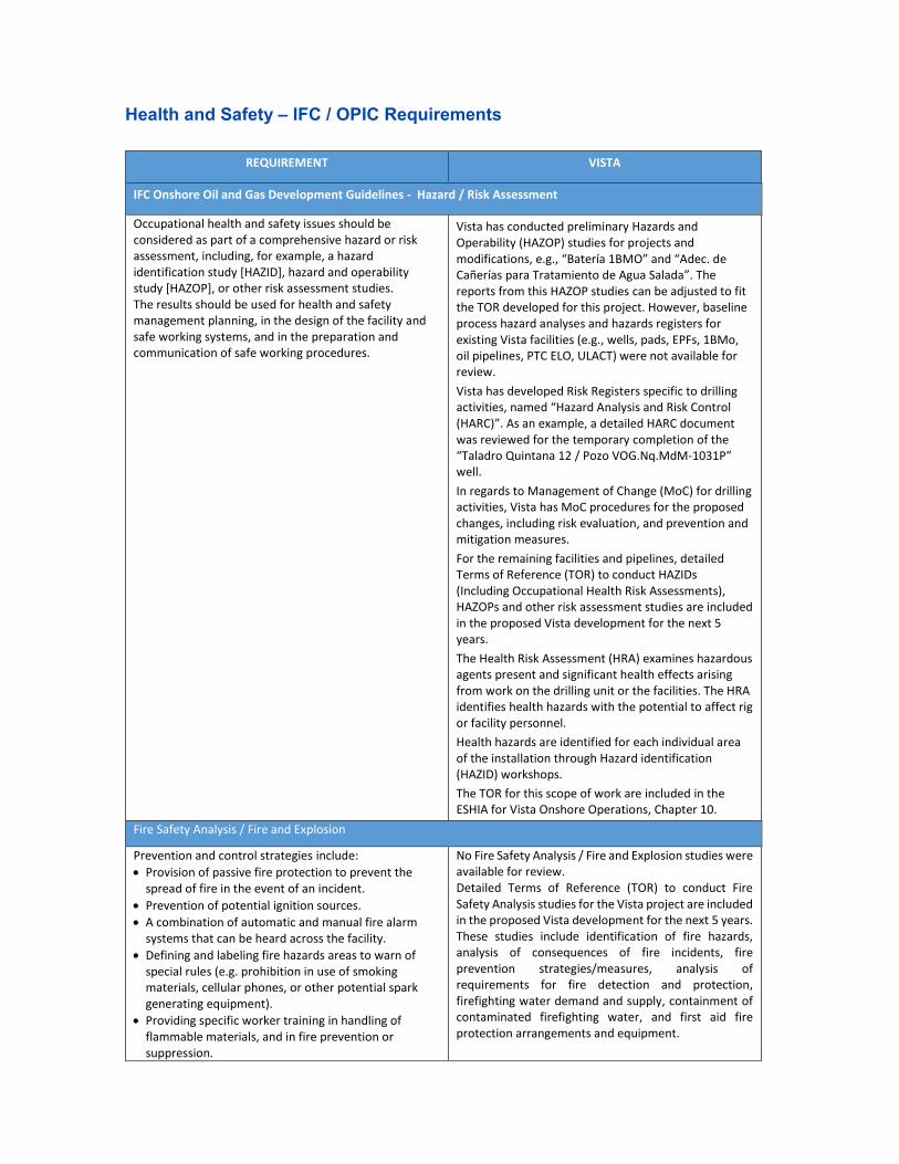
Health and Safety – IFC / OPIC Requirements
REQUIREMENT VISTA
IFC Onshore Oil and Gas Development Guidelines - Hazard / Risk Assessment
Occupational health and safety issues should be considered as part of a comprehensive hazard or risk assessment, including, for example, a hazard identification study [HAZID], hazard and operability study [HAZOP], or other risk assessment studies. The results should be used for health and safety management planning, in the design of the facility and safe working systems, and in the preparation and communication of safe working procedures.
Vista has conducted preliminary Hazards and Operability (HAZOP) studies for projects and modifications, e.g., “Batería 1BMO” and “Adec. de Cañerías para Tratamiento de Agua Salada”. The reports from this HAZOP studies can be adjusted to fit the TOR developed for this project. However, baseline process hazard analyses and hazards registers for existing Vista facilities (e.g., wells, pads, EPFs, 1BMo, oil pipelines, PTC ELO, ULACT) were not available for review.
Vista has developed Risk Registers specific to drilling activities, named “Hazard Analysis and Risk Control (HARC)”. As an example, a detailed HARC document was reviewed for the temporary completion of the “Taladro Quintana 12 / Pozo VOG.Nq.MdM-1031P” well.
In regards to Management of Change (MoC) for drilling activities, Vista has MoC procedures for the proposed changes, including risk evaluation, and prevention and mitigation measures.
For the remaining facilities and pipelines, detailed Terms of Reference (TOR) to conduct HAZIDs (Including Occupational Health Risk Assessments), HAZOPs and other risk assessment studies are included in the proposed Vista development for the next 5 years.
The Health Risk Assessment (HRA) examines hazardous agents present and significant health effects arising from work on the drilling unit or the facilities. The HRA identifies health hazards with the potential to affect rig or facility personnel.
Health hazards are identified for each individual area of the installation through Hazard identification (HAZID) workshops.
The TOR for this scope of work are included in the ESHIA for Vista Onshore Operations, Chapter 10.
Fire Safety Analysis / Fire and Explosion
Prevention and control strategies include:
• Provision of passive fire protection to prevent the spread of fire in the event of an incident.
• Prevention of potential ignition sources.
• A combination of automatic and manual fire alarm systems that can be heard across the facility.
• Defining and labeling fire hazards areas to warn of special rules (e.g. prohibition in use of smoking materials, cellular phones, or other potential spark generating equipment).
• Providing specific worker training in handling of flammable materials, and in fire prevention or suppression.
No Fire Safety Analysis / Fire and Explosion studies were available for review. Detailed Terms of Reference (TOR) to conduct Fire Safety Analysis studies for the Vista project are included in the proposed Vista development for the next 5 years. These studies include identification of fire hazards, analysis of consequences of fire incidents, fire prevention strategies/measures, analysis of requirements for fire detection and protection, firefighting water demand and supply, containment of contaminated firefighting water, and first aid fire protection arrangements and equipment.
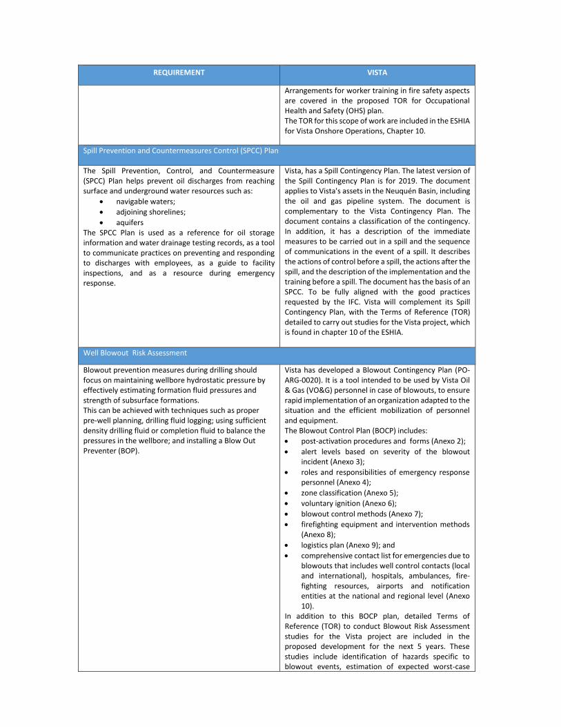
REQUIREMENT VISTA
Arrangements for worker training in fire safety aspects are covered in the proposed TOR for Occupational Health and Safety (OHS) plan. The TOR for this scope of work are included in the ESHIA for Vista Onshore Operations, Chapter 10.
Spill Prevention and Countermeasures Control (SPCC) Plan
The Spill Prevention, Control, and Countermeasure (SPCC) Plan helps prevent oil discharges from reaching surface and underground water resources such as:
• navigable waters;
• adjoining shorelines;
• aquifers The SPCC Plan is used as a reference for oil storage information and water drainage testing records, as a tool to communicate practices on preventing and responding to discharges with employees, as a guide to facility inspections, and as a resource during emergency response.
Vista, has a Spill Contingency Plan. The latest version of the Spill Contingency Plan is for 2019. The document applies to Vista's assets in the Neuquén Basin, including the oil and gas pipeline system. The document is complementary to the Vista Contingency Plan. The document contains a classification of the contingency. In addition, it has a description of the immediate measures to be carried out in a spill and the sequence of communications in the event of a spill. It describes the actions of control before a spill, the actions after the spill, and the description of the implementation and the training before a spill. The document has the basis of an SPCC. To be fully aligned with the good practices requested by the IFC. Vista will complement its Spill Contingency Plan, with the Terms of Reference (TOR) detailed to carry out studies for the Vista project, which is found in chapter 10 of the ESHIA.
Well Blowout Risk Assessment
Blowout prevention measures during drilling should focus on maintaining wellbore hydrostatic pressure by effectively estimating formation fluid pressures and strength of subsurface formations. This can be achieved with techniques such as proper pre-well planning, drilling fluid logging; using sufficient density drilling fluid or completion fluid to balance the pressures in the wellbore; and installing a Blow Out Preventer (BOP).
Vista has developed a Blowout Contingency Plan (PO-ARG-0020). It is a tool intended to be used by Vista Oil & Gas (VO&G) personnel in case of blowouts, to ensure rapid implementation of an organization adapted to the situation and the efficient mobilization of personnel and equipment. The Blowout Control Plan (BOCP) includes:
• post-activation procedures and forms (Anexo 2);
• alert levels based on severity of the blowout incident (Anexo 3);
• roles and responsibilities of emergency response personnel (Anexo 4);
• zone classification (Anexo 5);
• voluntary ignition (Anexo 6);
• blowout control methods (Anexo 7);
• firefighting equipment and intervention methods (Anexo 8);
• logistics plan (Anexo 9); and
• comprehensive contact list for emergencies due to blowouts that includes well control contacts (local and international), hospitals, ambulances, fire-fighting resources, airports and notification entities at the national and regional level (Anexo 10).
In addition to this BOCP plan, detailed Terms of Reference (TOR) to conduct Blowout Risk Assessment studies for the Vista project are included in the proposed development for the next 5 years. These studies include identification of hazards specific to blowout events, estimation of expected worst-case

REQUIREMENT VISTA
hydrocarbon discharges, consequences of potentially hazardous incidents, blowout prevention strategies/measures, and details of detection and protection. The TOR for this scope of work are included in the ESHIA for Vista Onshore Operations, Chapter 10.
Emergency Response Plan (ERP) / Emergency Preparedness and Response
Onshore oil and gas facilities should establish and maintain a high level of emergency preparedness to ensure incidents are responded to effectively and without delay. Potential worst-case accidents should be identified by risk assessment and appropriate preparedness requirements should be designed and implemented. An emergency response team should be established for the facility that is trained to respond to potential emergencies, rescue injured persons, and perform emergency actions. An Emergency Response Plan should be prepared that contains the following measures, at a minimum:
• A description of the response organization.
• Description of response procedures.
• Descriptions and procedures for alarm and communications systems.
• Precautionary measures for securing the Wells.
• Description of on-site first aid supplies and available backup medical support.
• Emergency Medical Evacuation procedures for injured or ill personnel.
Vista, has a Contingency Plan which applies to all its operations. The latest version of the Contingency Plan is from 2018. The document contains the description of those responsible for an emergency. A classification of A, B and C depending on the magnitude of the emergency. Description of facilities and operational emergency measures of the facilities. The document contains an Emergency Call Plan, an Evacuation Plan and an Emergency Action Plan. Also, Vista has developed emergency response plans specific to blowout events (see “Well Blowout Risk Assessment” section above). The document has the bases of an ERP. To be fully aligned with the good practices requested by the IFC. Vista will complement, its Contingency Plan, with the Terms of Reference (TOR) detailed to carry out studies of the Emergency Response Plan for the Vista project, found in chapter 10 of the ESHIA. These studies include identification of Major Accident Events (MAE), and description of the most severe consequences and highest potential for escalation for each emergency. The studies will consider initiating events, its causes, consequences and impact on the public, the environment or assets due to escalation of such events. The studies will also cover emergency levels, Emergency Response Organization, communication processes, emergency procedures and emergency medical evacuation.
Transportation
Oil and gas projects should develop a road safety management plan for the facility during all phases of operations. Measures should be in place to train all drivers in safe and defensive driving methods and the safe transportation of passengers. Speed limits for all vehicles should be implemented and enforced. Vehicles should be maintained in an appropriate road worthy condition and include all necessary safety equipment.
Vista will carry out a transportation management program, which considers IFC requirements and recommendations, as well as the coordination and management measures with local authorities and population surrounding the project. The Traffic Management Program for Vista Onshore Operations can be found in the ESHIA, section 8.1.8.
Hazardous Materials
Projects should have procedures in place that ensure compliance with local laws and international requirements applicable to the transport of hazardous materials.
UN Model Regulations of other international standards, as well as local requirements for land transport were included in the design of the hazardous materials transportation procedures. The Hazardous Substances Management Program for Vista Onshore Operations can be found in the ESHIA, section 8.1.6.
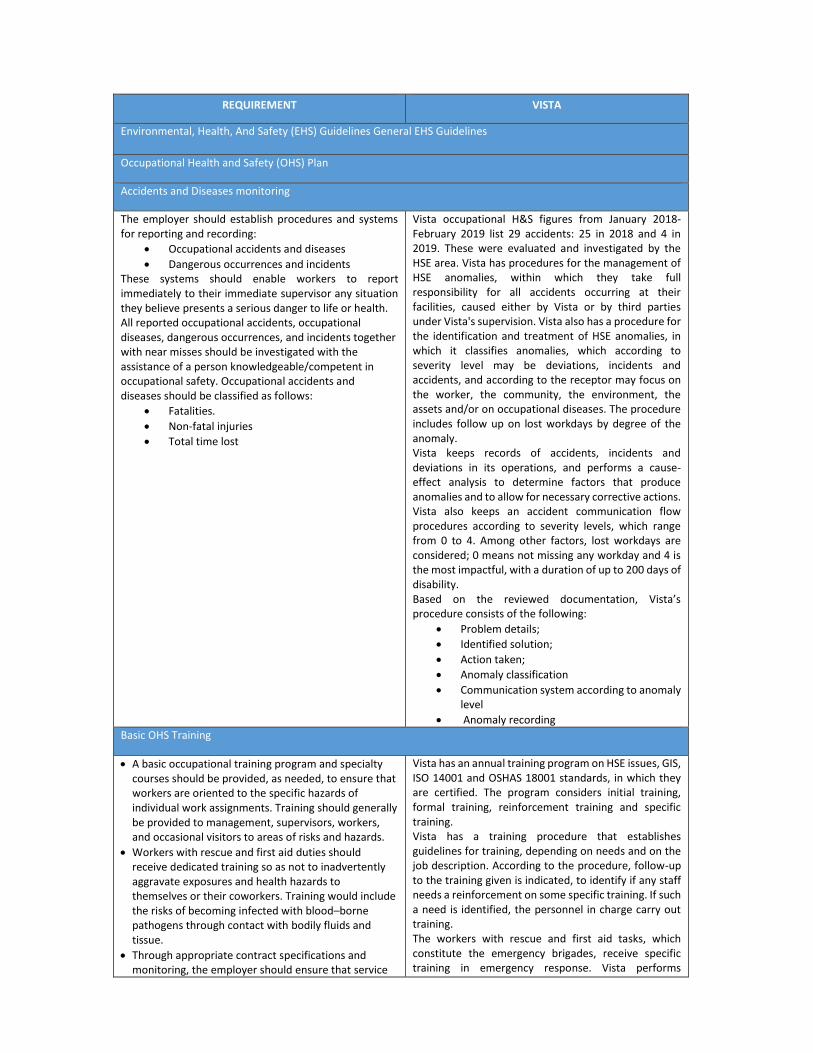
REQUIREMENT VISTA
Environmental, Health, And Safety (EHS) Guidelines General EHS Guidelines
Occupational Health and Safety (OHS) Plan
Accidents and Diseases monitoring
The employer should establish procedures and systems for reporting and recording:
• Occupational accidents and diseases
• Dangerous occurrences and incidents These systems should enable workers to report immediately to their immediate supervisor any situation they believe presents a serious danger to life or health. All reported occupational accidents, occupational diseases, dangerous occurrences, and incidents together with near misses should be investigated with the assistance of a person knowledgeable/competent in occupational safety. Occupational accidents and diseases should be classified as follows:
• Fatalities.
• Non-fatal injuries
• Total time lost
Vista occupational H&S figures from January 2018-February 2019 list 29 accidents: 25 in 2018 and 4 in 2019. These were evaluated and investigated by the HSE area. Vista has procedures for the management of HSE anomalies, within which they take full responsibility for all accidents occurring at their facilities, caused either by Vista or by third parties under Vista's supervision. Vista also has a procedure for the identification and treatment of HSE anomalies, in which it classifies anomalies, which according to severity level may be deviations, incidents and accidents, and according to the receptor may focus on the worker, the community, the environment, the assets and/or on occupational diseases. The procedure includes follow up on lost workdays by degree of the anomaly. Vista keeps records of accidents, incidents and deviations in its operations, and performs a cause-effect analysis to determine factors that produce anomalies and to allow for necessary corrective actions. Vista also keeps an accident communication flow procedures according to severity levels, which range from 0 to 4. Among other factors, lost workdays are considered; 0 means not missing any workday and 4 is the most impactful, with a duration of up to 200 days of disability. Based on the reviewed documentation, Vista’s procedure consists of the following:
• Problem details;
• Identified solution;
• Action taken;
• Anomaly classification
• Communication system according to anomaly level
• Anomaly recording
Basic OHS Training
• A basic occupational training program and specialty courses should be provided, as needed, to ensure that workers are oriented to the specific hazards of individual work assignments. Training should generally be provided to management, supervisors, workers, and occasional visitors to areas of risks and hazards.
• Workers with rescue and first aid duties should receive dedicated training so as not to inadvertently aggravate exposures and health hazards to themselves or their coworkers. Training would include the risks of becoming infected with blood–borne pathogens through contact with bodily fluids and tissue.
• Through appropriate contract specifications and monitoring, the employer should ensure that service
Vista has an annual training program on HSE issues, GIS, ISO 14001 and OSHAS 18001 standards, in which they are certified. The program considers initial training, formal training, reinforcement training and specific training. Vista has a training procedure that establishes guidelines for training, depending on needs and on the job description. According to the procedure, follow-up to the training given is indicated, to identify if any staff needs a reinforcement on some specific training. If such a need is identified, the personnel in charge carry out training. The workers with rescue and first aid tasks, which constitute the emergency brigades, receive specific training in emergency response. Vista performs
REQUIREMENT VISTA
providers, as well as contracted and subcontracted labor, are trained adequately before assignments begin.
supervision to contractor companies to verify that they receive training in the work they perform.
OHS Procedures
At all sites, it was reported that there is a formal permit to work (PTW) system in place for activities undertaken on site such as Working At Height, excavations, electrical work, hot work and confined spaces. These procedures are in force since 2010, implemented by other operators in the area, and are currently carrying out an action plan by Vista to review, merge and update the procedures.
Working At Height: Fall prevention and protection measures should be implemented whenever a worker is exposed to the hazard of falling more than two meters; into operating machinery; into water or other liquid; into hazardous substances; or through an opening in a work surface. Fall prevention may include:
• Installation of guardrails with mid-rails and toe boards at the edge of any fall hazard area
• Proper use of ladders and scaffolds by trained employees
• Use of fall prevention devices, including safety belt and lanyard travel limiting devices to prevent access to fall hazard area.
• Appropriate training in use, serviceability, and integrity of the necessary PPE.
Vista has a specific procedure for working at height, in which they implement fall prevention and protection measures. Working at height for Vista is considered whenever a worker is exposed to a 2 m fall, as indicated by the IFC. The procedure describes general guidelines such as:
• In work maneuvers that require suspension, a gondola or suspended access equipment must necessarily be used. When ladders are used on platforms or gratings above floor level, they must be tied down.
• Working maneuvers on lighting poles can be carried out with ladders, fastening the ladder to the top of the pole. The safety maneuver is completed with the use of a climber.
• Harness and lifeline should be used on sailor-type ladders that do not have a man guard. The area must be fenced to prevent the passage of unauthorized personnel while performing the work maneuver.
In addition to the general guidelines, a description of the procedures in the use of swings or suspended equipment for access and use of scaffolds is provided.
Confined Spaces And Confined Space Entry: Recommended management approaches include:
• Engineering measures should be implemented to eliminate, to the degree feasible, the existence and adverse character of confined spaces.
• Permit-required confined spaces should be provided with permanent safety measures for venting, monitoring, and rescue operations, to the extent possible.
• The atmosphere within the confined space should be tested to assure the oxygen content is between 19.5 percent and 23 percent, and that the presence of any flammable gas or vapor does not exceed 25 percent of its respective Lower Explosive Limit (LEL).
• If the atmospheric conditions are not met, the confined space should be ventilated until the target safe atmosphere is achieved, or entry is only to be undertaken with appropriate and additional PPE.
• Safety precautions should include Self Contained Breathing Apparatus (SCBA), lifelines, and safety watch workers stationed outside the confined space, with rescue and first aid equipment readily available.
Vista has a procedure for works in confined spaces, which is disseminated to workers who will perform such activities, as well as to Vista supervisors and contractors. This procedure details measures to perform a safe job avoiding accidents and incidents:
• Initial Evaluation: The confined spaces must be evaluated and classified prior to the preparation of the corresponding Entry Permit.
• Initial Measurement: testing must be performed at several points in the confined space to rule out the presence of flammable or toxic gases or vapors or deficiency or excess of oxygen, before starting work.
• Secure Confined Space: a) Flammability, toxicity and oxygen concentration levels are stable. b) If concentrations close to 50% of the CMP are found, tests that are more rigorous will be required to ensure that it is not exceeded. No place in space. c) Natural ventilation can be satisfactory if there are sufficient openings. However, in certain cases forced ventilation may be necessary. d) Do not use oxygen gas to modify the atmosphere of a confined space as it increases the risk of fire and explosion.
REQUIREMENT VISTA
• Confined Space not Safe to Enter Without Assisted Breathing Apparatus: Only under exceptional circumstances should you enter any space that cannot be certified as safe to enter without breathing apparatus and must be previously authorized by the Facilities Supervisor.
Welding / Hot Work: Hot work or welding may produce noxious fumes to which prolonged exposure can cause serious chronic diseases. Recommended measures include:
• Provision of proper eye protection such as welder goggles and/or a full-face eye shield for all personnel involved in, or assisting, welding operations.
• Special hot work and fire prevention precautions and Standard Operating Procedures (SOPs) should be implemented if welding or hot cutting is undertaken outside established welding work stations, including ‘Hot Work Permits, stand-by fire extinguishers, stand-by fire watch, and maintaining the fire watch for up to one hour after welding or hot cutting has terminated.
Personal Protective Equipment (PPE): Recommended measures for use of PPE in the workplace include:
• Active use of PPE if alternative technologies, work plans or procedures cannot eliminate, or sufficiently reduce, a hazard or exposure
• Identification and provision of appropriate PPE that offers adequate protection to the worker, co-workers, and occasional visitors, without incurring unnecessary
• inconvenience to the individual
• Proper maintenance of PPE, including cleaning when dirty and replacement when damaged or worn out. Proper use of PPE should be part of the recurrent training programs for employees.
• Selection of PPE should be based on the hazard and risk ranking described earlier in this section, and selected according to criteria on performance and testing established.
Vista has a procedure for hot work (welding and cutting), which is disseminated to the workers who carry out these activities, as well as to Vista's supervisors and contractors. This procedure details the measures to perform a safe job avoiding accidents and incidents. The procedure is constituted by the following points: General Description: All the jobs that are considered as hot work are described. A work permit must be obtained corresponding to the activity and the specific hot work procedures.
• The guidelines to be considered for the following works are described: Work with electric arc. Work with Oxyacetylene equipment
• Personal protective equipment (EPP) to be used by activity.
• Protective measures against smoke and gases.
Electrical Works: Exposed or faulty electrical devices, such as circuit breakers, panels, cables, cords and hand tools, can pose a serious risk to workers. Overhead wires can be struck by metal devices, such as poles or ladders, and by vehicles with metal booms. Recommended actions include:
• Marking all energized electrical devices and lines with warning signs.
• Locking out (de-charging and leaving open with a controlled locking device) and tagging-out (warning sign placed on the lock) devices during service or maintenance.
• Checking all electrical cords, cables, and hand power tools for frayed or exposed cords and following manufacturer recommendations for maximum permitted operating voltage of the portable hand tools.
• Appropriate labeling of service rooms housing high voltage equipment (‘electrical hazard’).
Establishing “No Approach” zones around or under high voltage power lines.
Vista has a procedure for electrical work, which is disseminated to workers who will perform these activities, as well as to Vista's supervisors and contractors. This procedure details the measures to perform a safe job avoiding accidents and incidents, also has a specific work permit form for electrical work. The procedure is constituted by the following points:
• Generalities: Reference and guidelines are mentioned for electrical work, and due caution to be adopted working with transformers and equipment that use refrigerating dielectric oil, avoiding the oil loss. The dielectric oil, free of PCBs, that is replaced, must be incorporated into the production circuit installation that the Electrical Maintenance Supervisor considers more appropriate.
• Personnel training: personnel who do electrical work must have required training to carry out the work safely.
• Voltage levels and distances: Voltage levels are classified from very low (50 volts) to very high (33000 volts). Minimum distances to be maintained between

REQUIREMENT VISTA
any non-isolated point of an electrical installation and the body of the operator or non-insulated tools used are indicated.
In addition, actions to perform work without tension and with tension are specified. Maintenance of energized equipment, labeling of energized equipment and signaling are also considered.
Personal Protective Equipment (PPE): Personal Protective Equipment (PPE) provides additional protection to workers exposed to workplace hazards in conjunction with other facility controls and safety systems. Recommended measures for use of PPE in the workplace include:
• Active use of PPE if alternative technologies, work plans or procedures cannot eliminate, or sufficiently reduce, a hazard or exposure.
• Identification and provision of appropriate PPE that offers adequate protection to the worker, co-workers, and occasional visitors, without incurring unnecessary
• Inconvenience to the individual.
• Proper maintenance of PPE, including cleaning when dirty and replacement when damaged or worn out. Proper use of PPE should be part of the recurrent training programs for employees.
Vista distributes the required Personal Protective Equipment (PPE) for each activity to personnel involved in the work. Vista has a PPE distribution record. During work permit preparation, required EPPs are considered for the work to be carried out. In addition, work areas have signs indicating the PPE required working in said area.
Lone and Isolated Workers: A lone and isolated worker is a worker out of verbal and line of sight communication with a supervisor, other workers, or other persons capable of providing aid and assistance, for continuous periods exceeding one hour. The worker is therefore at increased risk should an accident or injury occur.
In Vista operations, no worker performs activities alone. If work is done within the Project area, a contractor company supervisor and a Vista supervisor are always in communication. No work is done without first obtaining a work permit, which requires the presence of more than one person.
Occupational Health And Hygiene Monitoring
Noise: The limits of noise levels for heavy industry are 85 dB (A) for an 8-hour exposure and 110 dB (A) for a single exposure. The following recommendations are mentioned:
• No employee should be exposed to a noise level greater than 85 dB(A) for a duration of more than 8 hours per day without hearing protection. In addition, unprotected ears should not be exposed to a peak sound pressure level (instantaneous) of more than 140 dB(C).
• The use of hearing protection should be enforced actively when the equivalent sound level over 8 hours reaches 85 dB(A), the peak sound levels reach 140 dB(C), or the average maximum sound level reaches 110dB(A). Hearing protective devices provided should be capable of reducing sound levels at the ear to at least 85 dB(A).
• Prior to the issuance of hearing protective devices as the final control mechanism, use of acoustic insulating materials, isolation of the noise source, and other engineering controls should be investigated and implemented, where feasible.
• Periodic medical hearing checks should be performed on workers exposed to high noise levels.
Vista performs noise monitoring, based on its occupational noise protocol in the Borde Montuoso area. Monitoring is performed in the motor-compressor area of Borde Montuoso, in 9 workstations, once a year. Last monitoring is dated August 2018. Results in the motor-compressor area show compliance with Annex V of Resolution SRT 295/2003. However, 4 workstations, belonging to repair technician of the motor-compressor, exceed the exposure of 85 dB. Vista will continue to monitor noise, to evaluate and monitor exposed personnel, as well as to take necessary measures to minimize exposure, in addition to PPE use, which is properly signed in each work area.
REQUIREMENT VISTA
Illumination: Work area light intensity should be adequate for the general purpose of the location and type of activity, and should be supplemented with dedicated workstation illumination, as needed. Controls should include:
• Use of energy efficient light sources with minimum heat Emission.
• Undertaking measures to eliminate glare / reflections and flickering of lights.
• Taking precautions to minimize and control optical radiation including direct sunlight. Exposure to high intensity UV and IR radiation and high intensity visible light should also be controlled.
• Controlling laser hazards in accordance with equipment specifications, certifications, and recognized safety standards. The lowest feasible class Laser should be applied to minimize risks.
Vista performs illumination monitoring, based on its occupational illumination protocol in the Project area, once a year. Last monitoring is dated May 2019, in which different areas of Borde Montuoso were evaluated. Results in several areas were below national legislation established standards (Annex V of Resolution SRT 295/2003). Vista must replace illumination with higher capacity equipment, if greater precision is required in the works. In addition, Vista will continue to monitor the illumination parameter related to worker exposure.
Air Quality
Facilities should be equipped with a reliable system for gas detection that allows the source of release to be isolated and the inventory of gas that can be released to be reduced. Equipment isolation or the blowdown of pressure equipment should be initiated to reduce system pressure and consequently reduce the release flow rate. Gas detection devices should also be used to authorize entry and operations into enclosed spaces. Workforce training in safety equipment use and response in the event of a leak.
Detailed Terms of Reference (TOR) to conduct Fire Safety Analysis studies for the Vista project are included in the proposed Vista development for the next 5 years. These studies include analysis of requirements for fire detection and protection, firefighting water demand and supply, containment of contaminated firefighting water, and first aid fire protection arrangements and equipment. Arrangements for workforce training in safety equipment use and response aspects are covered in the proposed TOR for Emergency Response Plan (ERP) plan.
Poor air quality due to the release of contaminants into the work place can result in possible respiratory irritation, discomfort, or illness to workers. The following control measures are recommended:
• Where ambient air contains several materials that have similar effects on the same body organs (additive effects), taking into account combined exposures.
• Developing and implementing work practices to minimize release of contaminants into the work environment including: o Direct piping of liquid and gaseous materials o Minimized handling of dry powdered
materials; o Enclosed operations o Local exhaust ventilation at emission / release
points
Vista monitors work environment, based on its protocol of chemical substances. Monitoring carried out in November 2018, in the Medanito area, analyzes BTEX, nitrogen oxide, sulfur dioxide, hydrogen sulfide, ethanol, etc. Results obtained show that values comply with the national legislation (Resolution SRT 295/2003), except for the Benzene parameter, in the Medanito PTC area. Vista must continue to provide gas masks to workers in the area, and add a fume hood for hazardous chemicals. In addition, Vista must continue to monitor parameters related to worker exposure.