Embed Size (px)
Citation preview
z/OS
Hardware Configuration DefinitionPlanningVersion 1 Release 12
GA22-7525-14
���


z/OS
Hardware Configuration DefinitionPlanningVersion 1 Release 12
GA22-7525-14
���

NoteBefore using this information and the product it supports, read the information in “Notices” on page 119.
This edition applies to version 1, release 12, modification 0 of IBM z/OS (product number 5694-A01) and to allsubsequent releases and modifications until otherwise indicated in new editions.
This edition replaces GA22-7525-13.
© Copyright IBM Corporation 1989, 2010.US Government Users Restricted Rights – Use, duplication or disclosure restricted by GSA ADP Schedule Contractwith IBM Corp.
Contents
Figures . . . . . . . . . . . . . . . v
Tables . . . . . . . . . . . . . . . vii
About this information . . . . . . . . ixWho should use this information . . . . . . . ixHow to use this information . . . . . . . . . ixWhere to find more information . . . . . . . ix
Information updates on the Web. . . . . . . xThe z/OS Basic Skills Information Center. . . . x
How to send your comments to IBM xiiiIf you have a technical problem . . . . . . . xiii
Summary of changes . . . . . . . . xv
Chapter 1. Introduction . . . . . . . . 1What an I/O configuration is . . . . . . . . . 1I/O configuration definition process . . . . . . 2
Defining an I/O configuration to the software . . 2Defining an I/O configuration to the hardware . . 4Ensuring that the software and hardwaredefinitions match . . . . . . . . . . . . 6
Changing hardware and software I/O configurationdefinitions . . . . . . . . . . . . . . . 7
Making both hardware and software dynamicchanges . . . . . . . . . . . . . . . 8Making software-only dynamic changes . . . . 8
Using HCM for I/O definition . . . . . . . . 10
Chapter 2. Planning your I/Oconfiguration definition . . . . . . . 11Components of an I/O configuration . . . . . . 11
Logical partitions . . . . . . . . . . . 12Logical control units for I/O devices . . . . . 12Channel path numbering . . . . . . . . . 13Selection of the path to access an I/O device . . 13
Making decisions about your configuration. . . . 13IBM zSeries and System z platformconsiderations . . . . . . . . . . . . 14Defining operating system data. . . . . . . 15Defining switch data . . . . . . . . . . 15Defining processor, logical channel subsystem,partitions, channel path data, and subchannelsets . . . . . . . . . . . . . . . . 16Defining multiple subchannel sets . . . . . . 18Defining control unit data . . . . . . . . 19Defining I/O device data . . . . . . . . . 20Deciding about JES3 initialization stream checkerdata . . . . . . . . . . . . . . . . 20
Understanding a sysplex configuration . . . . . 21Defining coupling facility components in asysplex . . . . . . . . . . . . . . . 21
Managing IOCDSs and IPL attributes across asysplex . . . . . . . . . . . . . . . 26Using automatic tape switching . . . . . . 28
Defining shared channel paths . . . . . . . . 29Considerations for sharing channel paths . . . 30Defining logical partition access to a channelpath . . . . . . . . . . . . . . . . 30Processors communicating through sharedESCON or FICON channel paths . . . . . . 32Defining dynamically managed channel paths . . 33
Defining spanned channel paths . . . . . . . 35Considerations for spanning channel paths . . . 36
Creating over-defined channel paths . . . . . . 36FICON channels . . . . . . . . . . . . . 37
Channel path definitions . . . . . . . . . 37Dynamic activation . . . . . . . . . . . 37Migrating to FICON channels . . . . . . . 37
Defining special devices and special secondarydevices . . . . . . . . . . . . . . . . 40
Defining a special device (3390S) . . . . . . 40Defining a special secondary device (3390D) . . 41
Defining IQD CHPIDs and device types . . . . . 41Specifying an I/O device number . . . . . . . 42
Replicating I/O device numbers . . . . . . 43I/O device numbers for multiple exposuredevices . . . . . . . . . . . . . . . 43I/O device numbers for a parallel access volume 43Deleting parallel access volume alias devicesdynamically . . . . . . . . . . . . . 45Workload manager and dynamic aliasmanagement . . . . . . . . . . . . . 45
Specifying I/O device parameters and features . . 46Defining whether an I/O device will be dynamic 46Defining a tape device as automaticallyswitchable . . . . . . . . . . . . . . 48Defining the location of an I/O device's unitcontrol block (UCB) . . . . . . . . . . 49
Defining allocation preferences . . . . . . . . 53Understanding I/O device allocation in z/OS . . 53Defining device allocation in HCD . . . . . 59
Migrating to subchannel sets . . . . . . . . 62Scenario: All LPARs are z/OS V1R7 or later . . 62Scenario: Some LPARs are pre-z/OS V1R7 . . . 62Example of migrating devices betweensubchannel sets . . . . . . . . . . . . 63
Chapter 3. Specifying an I/Oconfiguration at IPL . . . . . . . . . 73Defining your initial I/O configuration . . . . . 73
IODF processing at IPL . . . . . . . . . 76Using your initial I/O configuration with specialsecondary (3390D) devices for reIPL . . . . . 81
Defining your I/O configuration for reIPL . . . . 82
© Copyright IBM Corp. 1989, 2010 iii
Chapter 4. Dynamically changing an I/Oconfiguration . . . . . . . . . . . . 83Actions to change your configuration dynamically 83Dynamically changing an I/O configuration inLPAR mode . . . . . . . . . . . . . . 84
Dynamic I/O configuration considerations . . . 85Example of deleting an I/O device in LPARmode . . . . . . . . . . . . . . . 85
Dynamically adding and removing logical partitionsto the I/O configuration . . . . . . . . . . 86Dynamically changing an I/O configuration in asysplex . . . . . . . . . . . . . . . . 87Dynamically changing component definitions . . . 88
Making dynamic changes to I/O devices . . . 88Making dynamic changes to channel paths . . . 92Making dynamic changes to control units . . . 95Making changes to coupling facility devices andcontrol units . . . . . . . . . . . . . 97
Dynamic I/O configuration in a multiple LCSSenvironment . . . . . . . . . . . . . . 99Testing dynamic activation . . . . . . . . . 102Recovery during dynamic configuration . . . . 103
Recovering dynamic configuration changes . . 103Recovering LPAR mode dynamic configurationchanges . . . . . . . . . . . . . . 104
Using HCM to migrate to IBM zSeriesz890 or z990 . . . . . . . . . . . . 107
Configurations with logical definitions only . . . 107Configurations including physical definitions. . . 108
Migrating to the dynamic capabilityprovided with HCD . . . . . . . . . 113UCB services considerations . . . . . . . . 113
Converting references to UCB services fordynamic . . . . . . . . . . . . . . 113Consideration when accessing UCB data . . . 115Services accepting a UCB copy . . . . . . 116
Specifying devices as dynamic after a migration 116
Accessibility . . . . . . . . . . . . 117Using assistive technologies . . . . . . . . 117Keyboard navigation of the user interface . . . . 117z/OS information . . . . . . . . . . . . 117
Notices . . . . . . . . . . . . . . 119Policy for unsupported hardware. . . . . . . 120Trademarks . . . . . . . . . . . . . . 120
Index . . . . . . . . . . . . . . . 123
iv z/OS V1R12.0 HCD Planning
Figures
1. Defining an I/O configuration to the software 22. Defining an I/O configuration to the hardware 53. Configuration Example. . . . . . . . . 114. Logical Control Unit Examples . . . . . . 125. Example of multiple subchannel set
configuration . . . . . . . . . . . . 196. Example of a Sysplex . . . . . . . . . 227. Support Elements connected to the Hardware
Management Console . . . . . . . . . 278. Shared Channel Paths . . . . . . . . . 309. Logical Addresses and Logical Partition
Numbers . . . . . . . . . . . . . 3310. Dynamic Channel Path Management . . . . 3411. Control Unit - Parallel access volume device
relationship . . . . . . . . . . . . 4412. Relationships among Generic and Esoteric
Device Groups . . . . . . . . . . . 5513. Example of Device Preference Table Affecting
UNIT=AFF. . . . . . . . . . . . . 5814. Example of Device Preference Table Affecting
the Default Unit-Affinity-Ignored Unit Name . 59
15. Original device configuration - I/O Device Listlaunched from the related OS configuration . . 68
16. Specify Subchannel Set ID. . . . . . . . 6917. Eligible Channel Subsystems . . . . . . . 6918. Eligible Operating System Configurations 6919. Build I/O Configuration Statements . . . . 7020. Migrate IOCP / MVSCP / HCPRIO Data 7121. New I/O Device List after migration . . . . 7222. Specifying IODF at IPL . . . . . . . . 7723. Sample processor running in LPAR mode 8624. Dynamic I/O reconfiguration management on
a z990 with compatibility support . . . . . 9925. Dynamically adding CHPIDs in a two-LCSS
environment on a z990 with compatibilitysupport . . . . . . . . . . . . . 100
26. Dynamically adding control units and devicesin a two-LCSS environment on a z990 withcompatibility support . . . . . . . . . 101
27. Dynamically adding shared resources in atwo-LCSS environment on a z990 withcompatibility support . . . . . . . . . 102
© Copyright IBM Corp. 1989, 2010 v

vi z/OS V1R12.0 HCD Planning
Tables
1. Location of Processor Configuration Token 72. I/O Component Identifiers To Avoid When
Using ICMF . . . . . . . . . . . . 243. Example of Installation Assignment of Alias
Device Numbers . . . . . . . . . . . 444. Description of Device Category Capability 475. Worksheet showing available ranges . . . . 676. Specifying an IODF for IPL . . . . . . . 80
7. Dynamic I/O Offline Requirements for DeviceCharacteristic Fields. . . . . . . . . . 91
8. Dynamic I/O Offline Requirements forChannel Path Fields. . . . . . . . . . 94
9. Dynamic I/O Offline Requirements for ControlUnit Fields . . . . . . . . . . . . . 96
10. Description of UCB Services . . . . . . 115
© Copyright IBM Corp. 1989, 2010 vii

viii z/OS V1R12.0 HCD Planning
About this information
This information describes how to define an I/O configuration using the HardwareConfiguration Definition (HCD) element of z/OS®. It includes information onplanning an I/O configuration, and specifying the configuration at IPL ordynamically, for a running system.
Who should use this informationThis information is intended for anyone who plans an installation's I/Oconfiguration and creates and coordinates action plans to change an I/Oconfiguration.
How to use this informationIf you are using this information for the first time, you should read all of thesections. Later, you might refer only to the information you need for a specific taskthat you are performing.
This information contains the following sections:v Chapter 1, “Introduction,” on page 1 presents an overview of I/O configuration
tasks using HCD and dynamic configuration.v Chapter 2, “Planning your I/O configuration definition,” on page 11 describes
the decisions you must make when planning your I/O configuration.v Chapter 3, “Specifying an I/O configuration at IPL,” on page 73 explains the
steps for defining your I/O configuration at IPL-time.v Chapter 4, “Dynamically changing an I/O configuration,” on page 83 explains
the steps for changing your I/O configuration on a running system.
Where to find more informationFor information about using the specific HCD panels, see z/OS HCD User's Guideand the HCD help. Also you might want to see the ITSO MVS/ESA HCD andDynamic I/O Reconfiguration Primer, SG24-4037, for an example of defining anentire, real-life configuration. This primer is available separately from z/OS.
For information about using Hardware Configuration Manager (HCM) for definingyour configuration, see z/OS and z/VM HCM User's Guide.
Where necessary, this information references information in other informations,using shortened versions of the information title. For complete titles and ordernumbers of the books for all products that are part of z/OS, see z/OS InformationRoadmap. The following table lists titles and order numbers for informationsavailable separately from z/OS.
Short title Publication titleOrdernumber
Enterprise System/9000Operator Guide
Enterprise System/9000 Models 190, 210, 260,320, 440, and 480 Operating and RecoveryGuide
GA23-0375
© Copyright IBM Corp. 1989, 2010 ix
Short title Publication titleOrdernumber
Enterprise System/9000Operator Guide
Enterprise System/9000 330, 340, 500, 580,620, and 720 Operator Guide
SC38-0085
Hardware Management ConsoleGuide
Hardware Management Console OperationsGuide
GC38-0470
IOCP User's Guide Input/Output Configuration Program User'sGuide/ ESCON Channel-to-Channel Reference
GC38-0401
IOCP User's Guide for IYPIOCP
Input/Output Configuration Program User'sGuide for IYP IOCP
SB10-7029
Stand-Alone IOCP User'sGuide
Stand-Alone IOCP, Generation 5, Generation 6 GC38-0458
Stand-Alone IOCP User'sGuide
Stand-Alone Input/Output ConfigurationProgram User's Guide
SB10-7032
ESCON CTC Reference ESCON Channel-to-Channel Reference SB10-7034
PR/SM Planning Guide PR/SM Planning Guide GA22-7236
Support Element OperationsGuide
Support Element Operations Guide GC38-3119
S/390 Parallel Enterprise Server- Generation 5 SystemOverview
S/390 Parallel Enterprise Server - Generation 5System Overview
GA22-7158
Additional hardware informations are available for specific processors. For titlesand order numbers of related informations, see the informationation that comeswith your processor.
Information updates on the WebFor the latest information updates that have been provided in PTF cover lettersand informationation APARs for z/OS, see the online information at:http://www.s390.ibm.com:80/bookmgr-cgi/bookmgr.cmd/BOOKS/ZIDOCMST/CCONTENTS
This information is updated weekly and lists informationation changes before theyare incorporated into z/OS publications.
The z/OS Basic Skills Information CenterThe z/OS Basic Skills Information Center is a Web-based information resourceintended to help users learn the basic concepts of z/OS, the operating system thatruns most of the IBM mainframe computers in use today. The Information Centeris designed to introduce a new generation of Information Technology professionalsto basic concepts and help them prepare for a career as a z/OS professional, suchas a z/OS system programmer.
Specifically, the z/OS Basic Skills Information Center is intended to achieve thefollowing objectives:v Provide basic education and information about z/OS without chargev Shorten the time it takes for people to become productive on the mainframev Make it easier for new people to learn z/OS.
x z/OS V1R12.0 HCD Planning

To access the z/OS Basic Skills Information Center, open your Web browser to thefollowing Web site, which is available to all users (no login required):http://publib.boulder.ibm.com/infocenter/zoslnctr/v1r7/index.jsp
About this information xi

xii z/OS V1R12.0 HCD Planning
How to send your comments to IBM
We appreciate your input on this publication. Feel free to comment on the clarity,accuracy, and completeness of the information or give us any other feedback thatyou might have.
Use one of the following methods to send us your comments:1. Send an email to [email protected]. Visit the Contact z/OS web page at http://www.ibm.com/systems/z/os/zos/
webqs.html3. Mail the comments to the following address:
IBM CorporationAttention: MHVRCFS Reader CommentsDepartment H6MA, Building 7072455 South RoadPoughkeepsie, NY 12601-5400U.S.A.
4. Fax the comments to us as follows:From the United States and Canada: 1+845+432-9405From all other countries: Your international access code +1+845+432-9405
Include the following information:v Your name and addressv Your email addressv Your telephone or fax numberv The publication title and order number:
z/OS V1R12.0 HCD PlanningGA22-7525-14
v The topic and page number related to your commentv The text of your comment.
When you send comments to IBM, you grant IBM a nonexclusive right to use ordistribute your comments in any way it believes appropriate without incurring anyobligation to you.
IBM or any other organizations will only use the personal information that yousupply to contact you about the issues that you submit.
If you have a technical problemDo not use the feedback methods listed above. Instead, do one of the following:v Contact your IBM service representativev Call IBM technical supportv Visit the IBM zSeries support web page at http://www.ibm.com/systems/z/
support/
© Copyright IBM Corp. 1989, 2010 xiii

xiv z/OS V1R12.0 HCD Planning

Summary of changes
Summary of changesfor GA22-7525-14z/OS Version 1 Release 12
The document contains information previously presented in z/OS HCD Planning,GA22-7525-13, which supports z/OS Version 1 Release 10.
New information
v With the I/O Autoconfiguration function, HCD allows users to discoverundefined FICON® storage devices (DASD and tape) connected to the processorvia a switch. For complete information, see z/OS HCD User's Guide.
v HCD supports the IBM® z10™ BC processor (processor type 2098-E10). Thisfunction is available as SPE since V1R10.
v For the z/TPF operating system, 3215 consoles are supported on channel pathsof type OSC. IOCP needs to distinguish between OSC-3270 and OSC-3215attachments. This is done through the CHPARM keyword on the CHPIDstatement. This function is available as SPE since V1R10.
Changed information
v Table 9 on page 96 is modified.v Table 8 on page 94 is valid for spanned channels.v The "Readers' Comments - We'd Like to Hear from You" section at the back of
this publication has been replaced with a new section “How to send yourcomments to IBM” on page xiii. The hardcopy mail-in form has been replacedwith a page that provides information appropriate for submitting readerscomments to IBM.
You may notice changes in the style and structure of some content in thisdocument—for example, headings that use uppercase for the first letter of initialwords only, and procedures that have a different look and format. The changes areongoing improvements to the consistency and retrievability of information in ourdocuments.
This document contains terminology, maintenance, and editorial changes. Technicalchanges or additions to the text and illustrations are indicated by a vertical line tothe left of the change.
Summary of changesfor GA22-7525-13z/OS Version 1 Release 10
The document contains information previously presented in z/OS HCD Planning,GA22-7525-12, which supports z/OS Version 1 Release 9.
New information
v Support for special devices and special secondary devices: HCD supports thedefinition of special devices— that is, devices defined in the alternate subchannelset (not subchannel set 0). By placing devices in the alternate subchannel set,
© Copyright IBM Corp. 1989, 2010 xv
you can keep some device numbers free for later use. For more information, see“Defining special devices and special secondary devices” on page 40.
v Information for new functions: For a description of the new functions in thisrelease, select Option 9 What's new in this release from the HCD Primary TaskSelection Panel. There you might also find information about any small productenhancements (SPEs) that might have been delivered after the publication of thisdocument.
This document contains terminology, maintenance, and editorial changes, includingchanges to improve consistency and retrievability.
Summary of changesfor GA22-7525-12z/OS Version 1 Release 9
The document contains information previously presented in z/OS HCD Planning,GA22-7525-11, which supports z/OS Version 1 Release 9.
New information
v Support for new hardware: HCD supports the IBM System z10 processor family.Selecting a 2097 processor type creates a maximum logical processorconfiguration. That is, HCD generates a processor configuration with fourchannel subsystems and 15 reserved partitions in each channel subsystem. Also,HCD generates two subchannel sets in each of the four channel subsystems andprovides for the maximum number of devices in each subchannel set.HCD support for predefining a maximum configuration for the System z10platform is available for z/OS 1.7 and later. For earlier releases, you must definethe configuration manually before creating the production IODF.
v Channel path type CIB for coupling over InfiniBand: The use of InfiniBandtechnology is supported through the new channel path CIB to emulate couplingconnections in the Host Communication Adapter (HCA). Support is provided onprocessor types 2094, 2096, and 2097 as point-to-point InfiniBand connectionsbetween CPCs. You can define this new channel path type as you would anyother channel path type, using for example, the HCD dialog or I/Oconfiguration statements. For more information, see “Defining InfiniBandconnections in a sysplex” on page 24.
Deleted information
v Support for processor types 4381, 9021, and 9121 has been removed.
This document contains terminology, maintenance, and editorial changes, includingchanges to improve consistency and retrievability.
Summary of changesfor GA22-7525-11z/OS Version 1 Release 9
The document contains information previously presented in z/OS HCD Planning,GA22-7525-10, which supports z/OS Version 1 Release 8.
New information
xvi z/OS V1R12.0 HCD Planning

v HCD supports Server Time Protocol (STP), a time synchronization feature that isdesigned to help multiple System z® servers maintain time synchronization witheach other. For more information, see “Defining Server Time Protocol (STP) linksin a sysplex” on page 24.
This document contains terminology, maintenance, and editorial changes, includingchanges to improve consistency and retrievability.
Summary of changes xvii

xviii z/OS V1R12.0 HCD Planning
Chapter 1. Introduction
This topic describes the process of defining and selecting an I/O configurationthrough the Hardware Configuration Definition (HCD) element of z/OS. It alsointroduces the concept of dynamic I/O configuration, which is a means of selecting orchanging the I/O configuration on a running system.
What an I/O configuration isAn I/O configuration is the set of hardware resources that are available to theoperating system, and the connections between these resources. Hardwareresources typically include:v Channelsv ESCON/FICON directors (switches)v Control unitsv Devices.
When you define an I/O configuration, you provide both physical and logicalinformation about these resources. For example, in defining a device you providephysical information, such as its type and model, and logical information, such asthe identifier you will assign to the device. Chapter 2, “Planning your I/Oconfiguration definition,” on page 11 describes the information you need toprovide for each resource.
You define an I/O configuration to both the operating system (software) and thechannel subsystem (hardware).
With Hardware Configuration Definition (HCD), you perform the hardware andsoftware I/O configuration processes through a single, interactive end-userinterface. As you enter data, HCD performs validation checking to help avoid dataentry errors before you attempt to use the I/O configuration.
The output of HCD is an I/O definition file (IODF), which contains I/Oconfiguration data. An IODF can define multiple hardware and softwareconfigurations to the z/OS operating system. When you activate an IODF, HCDdefines the I/O configuration to the channel subsystem or the operating system, orboth.
Through the HCD activate function or the MVS™ ACTIVATE operator command,you can make changes to the current configuration without having to initialprogram load (IPL) the software or power-on reset (POR) the hardware. Makingchanges while the system is running is known as dynamic configuration or dynamicreconfiguration.
You select the I/O configuration when you:v PORv IPLv Activate a dynamic configuration change.
IPL and activation require that you identify the IODF that contains the definitionof your configuration. A data set called an I/O configuration data set (IOCDS) is usedat POR. An IOCDS can be created from a configuration definition in an IODF. The
© Copyright IBM Corp. 1989, 2010 1
IOCDS contains the configuration for a specific processor, while the IODF containsconfiguration data for multiple processors.
I/O configuration definition processWhen you dynamically change an I/O configuration, you can change the I/Odefinitions for both the hardware and software, or for the software only, as follows:v Both hardware and software: Usually, you make simultaneous dynamic
configuration changes to both hardware and software configuration definitions.v Software only: In some cases, you might want to modify only the software
control structures, such as the unit control blocks (UCBs) and the eligible devicetable (EDT).
In some cases, you might make dynamic configuration changes to only hardware(a logical partition), which can affect the hardware configuration for otherpartitions. For more information, see “Dynamically changing an I/O configurationin LPAR mode” on page 84.
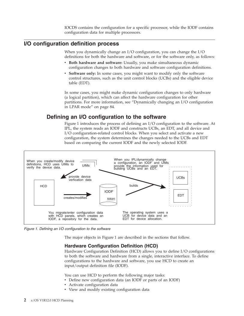
Defining an I/O configuration to the softwareFigure 1 introduces the process of defining an I/O configuration to the software. AtIPL, the system reads an IODF and constructs UCBs, an EDT, and all device andI/O configuration-related control blocks. When you select and activate a newconfiguration, the system determines the changes needed to the UCBs and EDTbased on comparing the current IODF and the newly selected IODF.
The major objects in Figure 1 are described in the sections that follow.
Hardware Configuration Definition (HCD)Hardware Configuration Definition (HCD) allows you to define I/O configurationsto both the software and hardware from a single, interactive interface. To defineconfigurations to the hardware and software, you use HCD to create aninput/output definition file (IODF).
You can use HCD to perform the following major tasks:v Define new configuration data (an IODF or parts of an IODF)v Activate configuration datav View and modify existing configuration data
UIMs
IODF
token
UCBs
EDT
When you create/modify devicedefinitions, HCD uses UIMs toverify the device data.
You migrate/enter configuration datawith HCD panels, which creates anIODF, a repository for the data.
builds
creates/modifies
provide deviceverfication data
The operating system uses aUCB for device data and anEDT for device allocation.
HCD
When you IPL/dynamically changea configuration, an IODF and UIMsprovide the information used forbuilding UCBs and an EDT.
Figure 1. Defining an I/O configuration to the software
2 z/OS V1R12.0 HCD Planning
v Maintain IODFs (such as, copy, import, and export)v Query and print configuration datav Migrate configuration datav Compare the active I/O configuration to a defined I/O configuration in an
IODF. For a description of the software required for this verification, see z/OSPlanning for Installation.
Input/output definition file (IODF)An input/output definition file (IODF) contains information about the I/Oconfiguration, such as:v Operating system datav Switch datav Device data, including EDT definitionv Processor datav Partition datav Channel path datav Control unit datav Channel subsystem data.
Three types of IODF exist: a work IODF, a validated work IODF, and a productionIODF.
Work IODFA work IODF allows you to create a new I/O configuration definition ormodify an existing I/O configuration definition. A work IODF provides away to build or modify an IODF before you use it to activate aconfiguration. It is a working copy, not suitable for IPL selection oractivated during dynamic activation. When a work IODF is ready to use,build a production IODF from it.
Validated work IODFA validated work IODF satisfies all validation rules for buildingproduction IODFs. It may lack at least one physical channel identifier(PCHID). In cooperation with HCD and the CHPID Mapping Tool avalidated IODF is required to accept new or updated PCHIDs. From such avalidated work IODF, an IOCP input deck suitable for use with the CHPIDMapping Tool is generated. As soon as all PCHIDs are inserted or updatedin the validated work IODF, the production IODF can be built. In HCD,you can use various methods to obtain a validated work IODF.
Production IODFA production IODF defines one or more valid I/O configurations. Aconfiguration in a production IODF can be activated dynamically orselected during IPL. Although you can build multiple production IODFs,only the one that is selected during IPL or activated during dynamicconfiguration is the active production IODF.
To change a configuration, create a work IODF from a production IODF. When youattempt to change a production IODF, HCD automatically copies the productionIODF into a work IODF so you can make your changes. When changes arecomplete, build a production IODF from the work IODF.
You can organize your configuration data in an IODF in multiple ways. Forexample:v You can define multiple operating system and processor configurations in one
IODF. The configurations can share common device definitions; this reduces themaintenance effort when devices are changed.
Chapter 1. Introduction 3
v For a processor that supports logical partitions, you can define theconfigurations for the processor and the operating systems running in the logicalpartitions of that processor in one IODF.
v From the IODF representing the complete configuration (master IODF), you cancreate IODFs containing parts of the whole configuration (for example, aprocessor with all of its relevant operating systems). These IODFs can bedistributed to a target system and used for activation. Note that the processortoken does not change during the distribution process. You can also mergedistributed IODFs in the master IODF. For information about handling largeIODFs, see z/OS HCD User's Guide.
v You can define several IODFs for the same hardware, with differentconfigurations for use in different circumstances. However, this approach is notrecommended, because you might need to update multiple IODFs when youchange the configuration.
Unit information module (UIM)A unit information module (UIM) contains the information and rules that HCDuses to process I/O device definitions. When you create an IODF, HCD uses UIMsto validate the device definitions that you enter. The system invokes UIMs at IPLor during a dynamic configuration change to build UCBs.
UIMs are provided with IBM product software for devices that z/OS supports. Fora non-supported device, you might be able to use a generic UIM or a UIM from asimilar IBM device. Also, if you have an MVSCP UIM for a device, you canconvert it to an HCD UIM.
For information about converting an MVSCP UIM to an HCD UIM, see z/OS MVSDevice Validation Support.
Unit control block (UCB)A unit control block (UCB) holds information about an I/O device, such as:v State information for the devicev Features of the device.
You can access information in UCBs using UCB services, such as UCBSCAN andUCBLOOK. At IPL or dynamic configuration, UCBs are built from HCD devicedefinition information in the IODF and UIMs. There is a UCB for each I/O devicein a configuration.
Eligible device table (EDT)An eligible device table (EDT) is an installation-defined and named representationof the I/O devices that are eligible for allocation. Using HCD, you define EDTinformation in an IODF. At IPL or dynamic configuration, information in the IODFand UIMs is used to build the EDT.
Defining an I/O configuration to the hardwareFigure 2 on page 5 introduces the process of defining an I/O configuration to thehardware. A configuration is defined to hardware when an IOCDS initializes theIOCDS information in the hardware system area (HSA) during a POR. Aconfiguration is also defined to hardware when information in HSA is updatedduring a dynamic configuration change. More detailed descriptions follow thefigure.
4 z/OS V1R12.0 HCD Planning
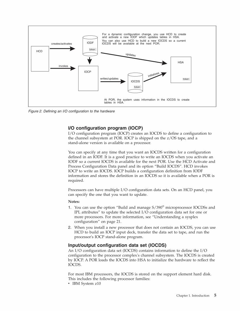
I/O configuration program (IOCP)I/O configuration program (IOCP) creates an IOCDS to define a configuration tothe channel subsystem at POR. IOCP is shipped on the z/OS tape, and astand-alone version is available on a processor.
You can specify at any time that you want an IOCDS written for a configurationdefined in an IODF. It is a good practice to write an IOCDS when you activate anIODF so a current IOCDS is available for the next POR. Use the HCD Activate andProcess Configuration Data panel and its option “Build IOCDS”. HCD invokesIOCP to write an IOCDS. IOCP builds a configuration definition from IODFinformation and stores the definition in an IOCDS so it is available when a POR isrequired.
Processors can have multiple I/O configuration data sets. On an HCD panel, youcan specify the one that you want to update.
Notes:
1. You can use the option “Build and manage S/390® microprocessor IOCDSs andIPL attributes” to update the selected I/O configuration data set for one ormore processors. For more information, see “Understanding a sysplexconfiguration” on page 21.
2. When you install a new processor that does not contain an IOCDS, you can useHCD to build an IOCP input deck, transfer the data set to tape, and run theprocessor's IOCP stand-alone program.
Input/output configuration data set (IOCDS)An I/O configuration data set (IOCDS) contains information to define the I/Oconfiguration to the processor complex's channel subsystem. The IOCDS is createdby IOCP. A POR loads the IOCDS into HSA to initialize the hardware to reflect theIOCDS.
For most IBM processors, the IOCDS is stored on the support element hard disk.This includes the following processor families:v IBM System z10
IOCP
writes/updatesinitializes
updates
HCD
creates/activates
invokes
IOCDS
token
IODF
token
HSA
token
At POR, the system uses information in the IOCDS to createtables in HSA.
For a dynamic configuration change, you use HCD to createand activate a new IODF which updates tables in HSA.
You can also use HCD to build a new IOCDS so a currentIOCDS will be available at the next POR.
Figure 2. Defining an I/O configuration to the hardware
Chapter 1. Introduction 5
v IBM System z9®
v IBM zSeries® 990v IBM zSeries 900v IBM zSeries 890v IBM zSeries 800.
For some earlier IBM processors, the IOCDS is stored on the processor controllerDASD.
Hardware system area (HSA)The hardware system area (HSA) contains tables that include information aboutthe current configuration.
Ensuring that the software and hardware definitions matchBefore your first dynamic configuration change, you must use HCD to create anIOCDS from the IODF that will be used for a subsequent IPL, then perform a PORusing that IOCDS. The POR places information about the hardware configurationin the hardware system area (HSA). The same IODF must be used at IPL to definethe software configuration.
Before you can perform a software and hardware dynamic change, your hardwareand software definitions must match. When you use the same IODF to define yoursoftware and hardware configurations, the software and hardware definitionsmatch.
However, there might be times when you want to change your software definition,for example, to temporarily run a test system. To change your software definition,you might perform a software-only dynamic change using a different IODF. In thiscase, your software and hardware definitions do not match and you cannotperform a full hardware and software dynamic configuration change.
To be able to make a dynamic hardware and software change, you can perform asoftware-only change using the IODF that was used to define the current hardwareconfiguration. This IODF is the one used to define the software and hardwareconfiguration at POR or at the last full software and hardware dynamicconfiguration change.
You could also perform a POR and the subsequent IPLs using the IODF with thecurrent software configuration so the software and hardware definitions match.
Of course, the software-only dynamic change does not require an IPL. You justneed to remember the IODF that you last used to define the software andhardware configuration so you can use it for the software-only change. This IODFis the one you used for the last POR or the last full software and hardwaredynamic change. When you use this IODF for the software-only change, thesoftware and hardware definitions match.
On the HCD View Active Configuration panel, you can view the IODF used forthe last POR or software and hardware dynamic configuration change. To displaythe panel, choose the “Activate or process configuration data” option from theHCD primary menu and then the “View active configuration” option.
You can also use a token called the processor configuration token to find the IODF.(Do not confuse the processor configuration token with the MVS I/O configurationtoken. The MVS I/O configuration token enables programs that requireconfiguration data to detect that dynamic changes have occurred.)
6 z/OS V1R12.0 HCD Planning
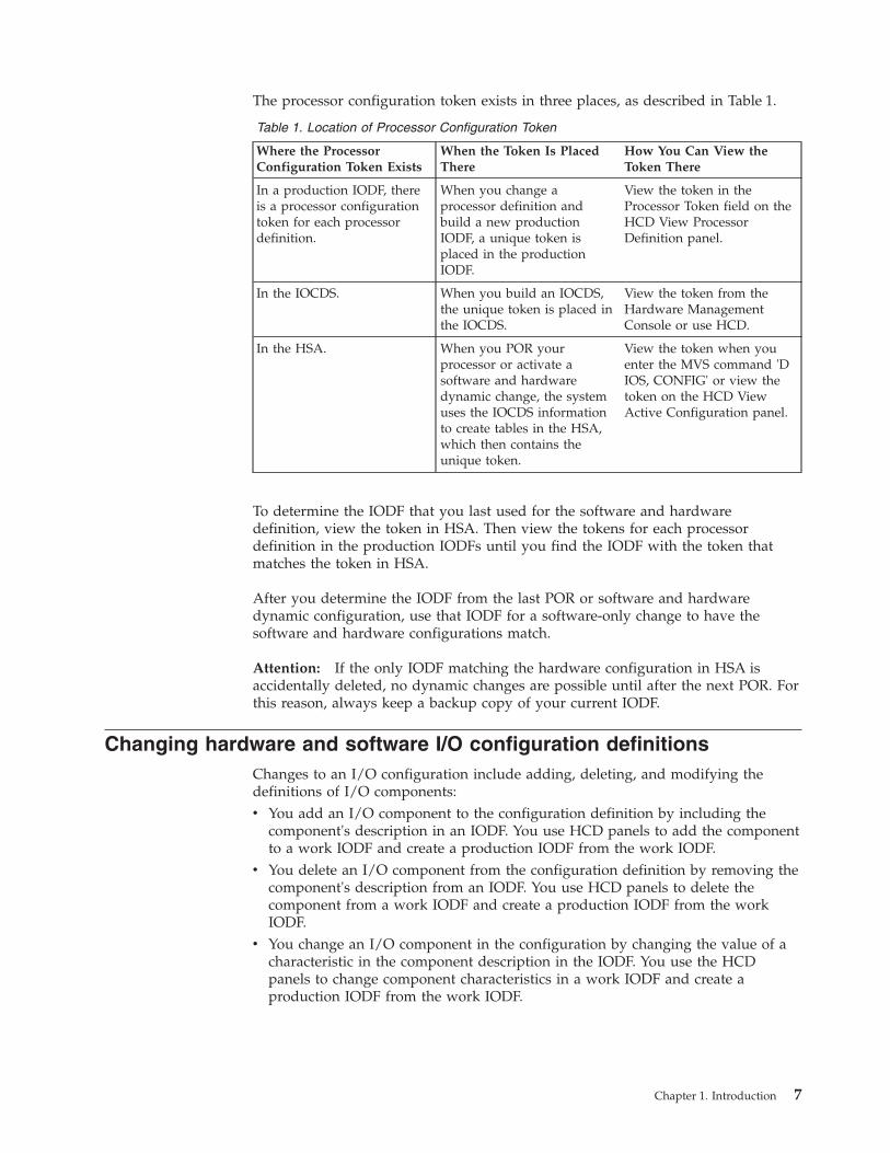
The processor configuration token exists in three places, as described in Table 1.
Table 1. Location of Processor Configuration Token
Where the ProcessorConfiguration Token Exists
When the Token Is PlacedThere
How You Can View theToken There
In a production IODF, thereis a processor configurationtoken for each processordefinition.
When you change aprocessor definition andbuild a new productionIODF, a unique token isplaced in the productionIODF.
View the token in theProcessor Token field on theHCD View ProcessorDefinition panel.
In the IOCDS. When you build an IOCDS,the unique token is placed inthe IOCDS.
View the token from theHardware ManagementConsole or use HCD.
In the HSA. When you POR yourprocessor or activate asoftware and hardwaredynamic change, the systemuses the IOCDS informationto create tables in the HSA,which then contains theunique token.
View the token when youenter the MVS command 'DIOS, CONFIG' or view thetoken on the HCD ViewActive Configuration panel.
To determine the IODF that you last used for the software and hardwaredefinition, view the token in HSA. Then view the tokens for each processordefinition in the production IODFs until you find the IODF with the token thatmatches the token in HSA.
After you determine the IODF from the last POR or software and hardwaredynamic configuration, use that IODF for a software-only change to have thesoftware and hardware configurations match.
Attention: If the only IODF matching the hardware configuration in HSA isaccidentally deleted, no dynamic changes are possible until after the next POR. Forthis reason, always keep a backup copy of your current IODF.
Changing hardware and software I/O configuration definitionsChanges to an I/O configuration include adding, deleting, and modifying thedefinitions of I/O components:v You add an I/O component to the configuration definition by including the
component's description in an IODF. You use HCD panels to add the componentto a work IODF and create a production IODF from the work IODF.
v You delete an I/O component from the configuration definition by removing thecomponent's description from an IODF. You use HCD panels to delete thecomponent from a work IODF and create a production IODF from the workIODF.
v You change an I/O component in the configuration by changing the value of acharacteristic in the component description in the IODF. You use the HCDpanels to change component characteristics in a work IODF and create aproduction IODF from the work IODF.
Chapter 1. Introduction 7
Notes:
1. Some changes to device characteristics cause the UCB to be deleted andadded again when the dynamic configuration change occurs. MessageIOS502I reports the deleted and added device.
2. Any dynamic change that causes a device UCB to be deleted and addedagain also causes the device MIH time interval to be reset to the default MIHsetting for its device class. To reestablish the previous MIH interval, enter theMVS command SETIOS MIH when the dynamic change is completed. Forinformation about the SETIOS MIH command, see z/OS MVS SystemCommands.
In most cases, you will make simultaneous dynamic configuration changes to bothhardware and software configuration definitions. However, in some cases making achange to only the software definition is useful. See “Making both hardware andsoftware dynamic changes” and “Making software-only dynamic changes.”
Making both hardware and software dynamic changesTo make hardware and software changes, follow these steps:1. Plan for changing the device configuration. For example, for adding devices,
check that the device code was loaded at the last IPL. For deleting devices,verify that the device is not needed by any application running in the processorand that the device is offline. For more information, see “Making dynamicchanges to I/O devices” on page 88.
2. Describe the new I/O configuration definition in an I/O definition file (IODF)that you create through HCD. For more information, see z/OS HCD User'sGuide.
3. Activate the new IODF using the HCD Activate New Configuration panel orthe ACTIVATE command.On the HCD Activate New Configuration panel, choose the “Activate hardwareand software configuration” option.If you are using the ACTIVATE command, do not specify the SOFT keywordfor hardware and software changes.
4. Use the HCD Build IOCDS task to write a new I/O configuration data set(IOCDS), if one does not already exist. You can make the new IOCDS thedefault for the next POR by issuing the ACTIVATE command with theACTIOCDS=xx keyword. If necessary update the LOADxx members for eachsystem to identify the new IODF.
5. Install the new I/O components that you have dynamically added through thenew IODF. As required, perform the following tasks:v Configure the channel pathsv Initialize devices, for example, format DASD with the volume serialv Enter the MVS VARY DEVICE command to make the device available to the
system, for example, 'VARY dddd,ONLINE'.
For more information about making dynamic changes, see Chapter 4, “Dynamicallychanging an I/O configuration,” on page 83.
Making software-only dynamic changesAlthough, you will usually make hardware and software dynamic changes, thereare times when a software-only change is useful:
8 z/OS V1R12.0 HCD Planning
v When the software I/O configuration does not match the hardware I/Oconfiguration. For example, when the IODF that you used for IPL does notcontain the hardware I/O configuration used to create the IOCDS.You can use the software-only change to synchronize the software definition tothe hardware definition so that a subsequent hardware and software change canbe activated. When a software-only change switches the IODF, the new IODFcan contain a processor configuration token that matches the current processorconfiguration token in HSA.
v When multiple logical partitions are running in LPAR mode. You makesoftware-only changes in all partitions except one; in the remaining partition,you make a software and hardware change. (See “Dynamically changing an I/Oconfiguration in LPAR mode” on page 84.)
v When z/OS is a guest operating system running under z/VM®.You cannot use dynamic configuration to make hardware changes in a z/OSguest system running under z/VM. However, you can use dynamicconfiguration to make software-only changes in the z/OS guest system. Thus,you can add new devices to a z/OS guest system using a z/VM interface (suchas ATTACH or DEFINE), then use dynamic configuration to make software-onlychanges in the z/OS guest system. However, you must run this configurationchange with the NOVALIDATE parameter.
v When z/OS is running on a processor that does not support dynamicconfiguration changes to hardware I/O configuration definitions. You can stillmake a software-only change, for example, to update the EDT or change thedefinition of a device from not shared to shared.
To make software-only changes, follow these steps:1. Plan for your changes to the device definitions in the configuration. For
example, for adding devices, check that the device code was loaded at the lastIPL. For deleting devices, verify that the device is not needed by anyapplication running in the processor. For more information, see “Makingdynamic changes to I/O devices” on page 88.
2. Describe the new I/O configuration definition in an I/O definition file (IODF)that you create through HCD. See z/OS HCD User's Guide.
3. Activate the new IODF using the HCD Activate New Configuration panel orthe ACTIVATE command:v On the HCD Activate New Configuration panel, choose either of the
following options:– Activate software configuration only and validate hardware changes– Activate software configuration onlyChoose the “Activate software configuration only and validate hardwarechanges” option to validate that I/O components being deleted are not inuse.
v On the ACTIVATE command, specify the SOFT keyword for software-onlychanges.
For more information, see Chapter 4, “Dynamically changing an I/Oconfiguration,” on page 83.
Chapter 1. Introduction 9
Using HCM for I/O definitionHardware Configuration Manager (HCM), an optional feature of z/OS, works withHCD to provide a set of graphical and text configuration reports. HCMcomplements HCD by adding information about the physical properties of theprocessors and I/O configurations to the logical information that HCD provides.For example, the physical information about processors and I/O configurationsincludes details about the ESCON® and FICON infrastructure such as cables,distribution panels, and patch panels.
HCM works as a client server application with HCD and uses the HCD validationprocess. Working with HCD, HCM combines logical and physical definitions into asingle process. The HCM graphical interface allows users to define theconfigurations and to locate and display configuration objects and theirconnections. It also allows users to display operational data, such as system statusinformation, and to operate on switches using an interface to the I/O operationscomponent of System Automation for OS/390® (formerly known as ESCONManager). The HCM graphical interface is helpful when planning configurationchanges and doing problem determination.
For more information about HCM, see z/OS and z/VM HCM User's Guide.
10 z/OS V1R12.0 HCD Planning
Chapter 2. Planning your I/O configuration definition
Before you can create an IODF, you must first gather the necessary information.
This topic includes the following information:v “Components of an I/O configuration”v “Making decisions about your configuration” on page 13v “Understanding a sysplex configuration” on page 21v “Defining shared channel paths” on page 29v “Specifying an I/O device number” on page 42v “Specifying I/O device parameters and features” on page 46v “Defining allocation preferences” on page 53v “Migrating to subchannel sets” on page 62.
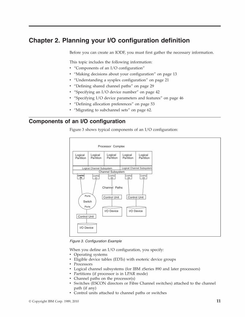
Components of an I/O configurationFigure 3 shows typical components of an I/O configuration:
When you define an I/O configuration, you specify:v Operating systemsv Eligible device tables (EDTs) with esoteric device groupsv Processorsv Logical channel subsystems (for IBM zSeries 890 and later processors)v Partitions (if processor is in LPAR mode)v Channel paths on the processor(s)v Switches (ESCON directors or Fibre Channel switches) attached to the channel
path (if any)v Control units attached to channel paths or switches
Channel Subsystem
LogicalPartition
LogicalPartition
LogicalPartition
LogicalPartition
LogicalPartition
I/O DeviceI/O Device
I/O Device
Channel Paths
Processor Complex
Switch
Ports
Ports
CHPID00
CHPID00
CHPID01
CHPID02
CHPID03
CHPID04
Control Unit Control Unit
Control Unit
Logical Channel Subsystem Logical Channel Subsystem
Figure 3. Configuration Example
© Copyright IBM Corp. 1989, 2010 11
v I/O devices connected to the control units.
Logical partitionsThe Processor Resource/System Manager (PR/SM™) feature allows a singleprocessor to run multiple operating systems in logically partitioned (LPAR) mode.Each operating system has its own logical partition, which is a separate set ofsystem resources including:v A portion of storage (central, or central and expanded)v One or more central processors. The processors can be dedicated or shared.
LPAR mode is established when the processor has had the PR/SM feature installedand has been divided into logical partitions.
Only LPAR mode (not basic mode) is supported on IBM zSeries 890, zSeries 990,System z9 or System z10 processors.
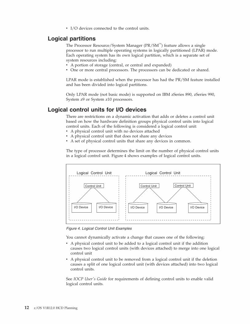
Logical control units for I/O devicesThere are restrictions on a dynamic activation that adds or deletes a control unitbased on how the hardware definition groups physical control units into logicalcontrol units. Each of the following is considered a logical control unit:v A physical control unit with no devices attachedv A physical control unit that does not share any devicesv A set of physical control units that share any devices in common.
The type of processor determines the limit on the number of physical control unitsin a logical control unit. Figure 4 shows examples of logical control units.
You cannot dynamically activate a change that causes one of the following:v A physical control unit to be added to a logical control unit if the addition
causes two logical control units (with devices attached) to merge into one logicalcontrol unit
v A physical control unit to be removed from a logical control unit if the deletioncauses a split of one logical control unit (with devices attached) into two logicalcontrol units.
See IOCP User's Guide for requirements of defining control units to enable validlogical control units.
Control UnitControl UnitControl Unit
I/O DeviceI/O Device I/O DeviceI/O Device I/O Device
Logical Control UnitLogical Control Unit
Figure 4. Logical Control Unit Examples
12 z/OS V1R12.0 HCD Planning
Channel path numberingA channel path is logically identified by a two-digit hexadecimal number called achannel path identifier (CHPID). Some model processor complexes can have gapsin their channel path identifier (CHPID) numbering scheme due to the mix andnumber of installed parallel and ESCON channels. See the IOCP User's Guide for adescription of the restrictions this might cause.
Selection of the path to access an I/O deviceYou can specify a preferred channel path to an I/O device. When you do notspecify a preferred path, the channel subsystem uses a rotation order for theinitiation of I/O requests to a device.
The rotation order is based on the:v Control unit number you specify for a control unit that attaches a devicev Order channel paths are specified on a control unit
The channel subsystem tries the first channel path you specify for each control unitthat attaches to the device, beginning with the lowest numbered control unit. Thechannel subsystem then tries the second channel path, if specified, for each controlunit that attaches to the device, beginning with the lowest numbered control unit.The channel subsystem repeats this process until all specified channel paths for allcontrol units attached to the device have been tried. See IOCP User's Guide formore information.
Using HCD, you can supply the information to establish preferred channel pathsand the rotation order. To specify a preferred channel path, when you define adevice, you specify the CHPID for the channel path in the Preferred CHPID fieldon the HCD “Device / Processor Definition” panel. When you assign control unitnumbers and specify channel paths for control units, you can consider the rotationorder to control the selection path order for devices.
Making decisions about your configurationBefore you actually define your configuration, decide on and collect the generalinformation about the configuration components in a configuration plan. HCDprovides reports about the processor support and UIMs installed on your system.These reports include information about device types, their parameters andfeatures, and current connectivity rules. The Supported Hardware Report and theI/O Definition Reference are available as batch reports. After you define yourconfiguration, you can use the reports that HCD generates to track updates to yourplan.
After you create your configuration plan, use the HCD panels to specify theinformation about configuration components. HCD provides interactive help todescribe the information for each field. The panels also enable you to request a listof options for some fields. For example, for the Processor Type and Model field,you can display a list of the available processor types to choose from with thePrompt function in the HCD panel.
The plan outline that follows shows the order that you would most likely follow todefine your configuration:1. Define operating system data2. Define switch data3. Define processor, logical channel subsystem, partition, channel path data, and
subchannel sets
Chapter 2. Planning your I/O configuration definition 13
4. Define control unit data5. Define I/O device data6. Decide about JES3 initialization stream checker data (if you are running JES3)
IBM zSeries and System z platform considerationsIBM System z and zSeries environments support the following:v More than 15 logical partitions. Only LPAR mode is supported; you cannot run
in basic mode on these processors.v Multiple logical channel subsystems, which allow you to logically partition your
physical channel resources to accommodate large-scale enterprise workloadconnectivity and high bandwidth demands.– The z890 processor supports up to two logical channel subsystems.– The z990 supports up to four logical channel subsystems, depending on z/OS
release and z990 LIC level. See “z890 and z990 processor support by releaseand LIC level.”
Each logical channel subsystem can have up to 256 CHPIDs and 15 logicalpartitions. Note that even a z990 at a level that supports 4 logical channelsubsystems can still only have a total of 30 logical partitions for the processor.
v On an IBM System z9 with z/OS V1R7 or later installed, you can define up totwo subchannel sets per channel subsystem. In subchannel set 0 (SS0) you candefine up to 63.75K devices. In subchannel set 1 (SS1) you can define 64K aliasdevices. For additional information on defining subchannel sets, see “Definingmultiple subchannel sets” on page 18.
v Channels can be shared, or spanned, across logical channel subsystems. Spannedchannels allow you to minimize the number of physical CHPIDs, switch portsand cables required. Channels that would otherwise be under-utilized couldhave their utilization increased by spanning them across logical channelsubsystems. See “Defining spanned channel paths” on page 35 for moreinformation.
v You no longer specify the expansion percentages for HSA on the CPC imageprofile on the hardware management console (HMC). The expansion percentagesare replaced by the maximum number of devices value when you define each ofthe logical channel subsystems. If you want to change this value, you must PORthe machine. The default for the maximum number of devices value for eachlogical channel subsystem is 63K, so plan carefully to avoid wasting HSA space.On an IBM System z9 or later processor, you have two maximum number deviceparameters; one for SS0 with the default of 63.75K, and another for SS1 with thedefault of 0.
z890 and z990 processor support by release and LIC levelIBM z890 and z990 processor support varies by release and LIC level.
z890 and z990 compatibility support allows your z/OS system to run on or coexistwith systems running on the z890 or z990 processor. Compatibility allows you todefine multiple logical channel subsystems and up to 30 logical partitions, butz/OS can only run in and perform a dynamic ACTIVATE of hardware changes fora logical channel subsystem of 0. For details, see “Dynamic I/O configuration in amultiple LCSS environment” on page 99.
z890 and z990 exploitation support lets you run your z/OS system on a z890 orz990 processor in a logical partition in any logical channel subsystem, and allowsdynamic ACTIVATE of hardware changes for any logical channel subsystem.v On a z890 or z990 exploitation level or later, or a z990 with the May 2004
version of LIC and HCD APAR OA03689 installed, you can define up to fourlogical channel subsystems and to define additional channel types as spanned.
14 z/OS V1R12.0 HCD Planning
v On a z/OS V1R6 system running on either a z890 or z990 processor, you canpredefine one or more reserved logical partitions, which you can later add to theI/O configuration using dynamic I/O to assign a name and resources. You canalso disconnect the partition from any assigned resources using dynamic I/O.The partition will revert back to being a reserved logical partition — the spaceused by the partition is not returned to the available pool of storage. See“Dynamically adding and removing logical partitions to the I/O configuration”on page 86 for more information.Note that on processors prior to the z890 or z990, you cannot dynamically addor delete a logical partition without building a new IOCDS and performing aPOR.
Defining operating system dataTo define the operating system configuration you need to decide on:v An eight byte EBCDIC identifier for the configurationv For eligible device tables (EDTs) for I/O devices:
– Decide how many EDTs to define– Specify a two digit identifier for each EDT, for example, 20– Decide how many esoteric device groups to define in each EDT– Specify a name for each group
See “Defining allocation preferences” on page 53 for a description of EDTs andesoteric groups. When you define a specific device to your configuration, youspecify the esoteric group in which to include the device as described in “DefiningI/O device data” on page 20.
Defining switch dataUsing HCD, you can define both ESCON switches (ESCON directors, such as9032–5) and Fibre Channel (FC) switches. You can define an FC switch as a FICONFC switch (type 2032) or as a generic FC switch (type FCS). The FICON FC switchsupports an internal switch control unit and device whereas the generic FC switchdoes not.
To define switches in your configuration, you need to know the switch type (forexample, 9032–3 or 9032–5). You need to decide on:v Switch ID, such as 01v Switch control unit number and switch device number: You must define a
switch control unit and device to be able to use HCD and the I/O operationscomponent of System Automation for OS/390 (formerly known as ESCONManager) to update the switch configuration and to validate the switch data.When you specify a control unit number and device number in the HCD AddSwitch panel, a control unit and device are defined to be the same type as theswitch. Note that the FCS switch does not support a switch control unit anddevice.
v Description: text that you use to describe the switch
You also use HCD to define the connections of the switch ports to channels orcontrol units. You can use HCD to define a matrix of all possible connectionsbetween any two ports as well. The matrix information can be migrated into HCDfrom an ISPF table containing a switch configuration from System Automation forOS/390, from an active ESCON director (ESCD), a FICON director, or from asaved ESCD file. Use the “Migrate Switch Configuration Data” option on the HCDMigrate Configuration Data panel.
Chapter 2. Planning your I/O configuration definition 15
Similarly, you can use HCD to generate a matrix containing the defined logicalconnections between channel paths and control units.
Defining switch data is optional unless a system running the I/O operationscomponent of System Automation for OS/390 must reconfigure the switch.
Defining processor, logical channel subsystem, partitions,channel path data, and subchannel sets
To define processors in your configuration, you need to know:v Processor type and model.v For a central processor complex (CPC) controlled through the Hardware
Management Console, you require the SNA address of its support element. Formore information, see “Understanding a sysplex configuration” on page 21.
v Serial number: If you specify a serial number, the system uses the number toverify that it is updating the correct processor during IOCDS download. Thisverification does not occur for a CPC that has a SNA address defined in HCD.
v Support level of the processor, for example if it supports ESCON channels. Ifonly one support level is available for the processor type/model, you do nothave to specify the support level in HCD.
To define processors in your configuration, you must:v Choose an 8-byte alphanumeric processor identifier: a name that you assign to
identify the processor in HCD, such as RN01PROCv Select a processor mode: BASIC or LPAR
If a processor is in LPAR mode, you must define partitions in yourconfiguration.
v If the processor supports multiple logical channel subsystems, you must specifythe number of logical channel subsystems (at least one).
v Supply a description: text that you use to describe the processor.
To define multiple logical channel subsystems in your configuration, you requirean IBM zSeries 890 or later processor.
Also, you must determine:v How many logical channel subsystems to define. The number you are allowed
to define depends on your processor:– If you have either a z990 processor with the pre-May 2004 version of Licensed
Internal Code (LIC) or a z890 processor, you can define up to two logicalchannel subsystems.
– If you have a z990 with the May 2004 version of LIC and HCD APAROA03689, you can define up to four logical channel subsystems.
v Which partitions are assigned to each logical channel subsystem.v Which control unit information, such as channel paths and link addresses are
defined for each logical channel subsystem for a processor.v What channel path access, candidate lists, and preferred paths to define for a
logical channel subsystem.v Which channel paths are defined to each logical channel subsystem. Note that
when you define a logical channel path, you must associate it with a logicalCHPID on the HCD panels.
v How many devices are allowed . The value you choose should include thenumber of devices you define in your current I/O configuration plus room forgrowth in your configuration.
16 z/OS V1R12.0 HCD Planning
On an IBM zSeries 890 or later processor, you no longer specify the expansionpercentages for HSA on the CPC image profile on the hardware managementconsole (HMC). The expansion percentages are replaced by the maximumnumber of devices value when you define each of the logical channelsubsystems. If you want to change this value, you must POR the machine. Thedefault for the maximum number of devices value for each logical channelsubsystem is 63K, so plan carefully to avoid wasting HSA space.
v Whether to predefine SS1 for each logical channel subsystem (on an IBM Systemz9 or later processor). You can use SS1 only for parallel access volume aliasdevices. For more information, see “Defining multiple subchannel sets” on page18 and “Deleting parallel access volume alias devices dynamically” on page 45.
v How to map CHPIDs across multiple logical channel subsystems. CHPIDs arenot unique across multiple logical channel subsystems, so to map a logicalCHPID to a physical channel, you must specify a physical channel ID (PCHID).
To define partitions, you must choose:v Partition name, such as MVS01 and RTR01v Partition number/MIF image ID.
On a processor prior to the z890 or z990, the partition number you specify onthe "Add partition" panel in HCD when you define your partitions is also usedas the Multiple Image Facility (MIF) image ID. MIF enables logical partitions toshare channel paths and coupling facility sender channel paths between logicalpartitions within a processor complex.On an IBM zSeries 890 or later processor, the partition number and the MIFimage ID are not the same. When you define your partitions on one of theseprocessor using the "Add partition" panel in HCD, the value you specify is theMIF image ID, not the partition number. The system uses information in IOCDSto assign a partition number when you POR the machine. Because the value youspecify on the HCD panel is a MIF image ID, the value must be between X'1'and X'F' and be unique within the logical channel subsystem. See “Processorscommunicating through shared ESCON or FICON channel paths” on page 32 formore information.
v Whether a partition will run an operating system, a coupling facility, or either,depending on whether coupling facility support is loaded. See “Understanding asysplex configuration” on page 21 for more information.
v Description: text that you use to describe the partitionv On a z890 or z990 processor with a supporting level of microcode, you must
decide whether to predefine one or more reserved logical partitions. Doing soreserves the needed space for the extra partitions in the IOCDS and HSA. Later,as needed, you can assign the partitions a name and assign resources to themusing dynamic I/O. For more information, see “Dynamically adding andremoving logical partitions to the I/O configuration” on page 86.
To define channel paths in your configuration, you first make your physicallayout decisions such as your CHPID numbers for channels, number of channelpaths, channel path type, and switch information if channel path(s) are connectedto a switch. The switch information includes entry switch ID, ports, and dynamicswitch ID. Then you need to decide on:v Operation Mode: If a processor is in LPAR mode, you can specify the operation
mode, which indicates the access that logical partitions will have to a channelpath. The operation modes that you can specify for channel paths in HCD are:– Dedicated allows only one logical partition to access a channel path.
Chapter 2. Planning your I/O configuration definition 17
– Reconfigurable allows only one logical partition at a time to access a channelpath, but you can reconfigure that channel path from one logical partition toanother. You reconfigure a channel path using the MVS CONFIG CHP(xx)command.
– Shared allows more than one logical partition to access a channel pathsimultaneously. For information about shared channel paths, see “Definingshared channel paths” on page 29.You can only specify shared mode when the support level of the processorhas Multiple Image Facility (MIF) capability. See “Defining shared channelpaths” on page 29 for a description of the advantages and considerations forusing shared channel paths.
– Spanned allows partitions in more than one logical channel subsystem toshare the same channel.Note that not all types of channel paths can be defined as spanned. See“Defining spanned channel paths” on page 35.
v Access and Candidate Lists: These lists specify which logical partitions canaccess a channel path. See “Defining logical partition access to a channel path”on page 30 for information.
v Dynamic channel path management: If you are using dynamic channel pathmanagement, a subfunction of IRD, you must define which channels and controlunits will participate. See “Defining dynamically managed channel paths” onpage 33 for information.
v Intra-CPC communication: If you are using HiperSocket Accelerator, see“Defining IQD CHPIDs and device types” on page 41 for information.
v Inter-CPC communication: If you are using a timing link, see “Defining ServerTime Protocol (STP) links in a sysplex” on page 24 for information.
v For a sysplex that uses the coupling facility, you need to decide on theconnections between coupling facility receiver and coupling facility senderchannels. The connections can be established using the 'View CF channel pathconnectivity' action on the HCD 'Channel Path List' panel. See “Understanding asysplex configuration” on page 21 for more information.
v On an IBM zSeries 890 or later processor, you must specify a two-byte physicalchannel ID (PCHID) for each external channel to map the logical CHPID to itsphysical channel. You can specify them manually or use the zSeries CHPIDmapping tool. You can get the CHPID mapping tool from Resource Link™ at:http://www.ibm.com/servers/resourcelink
Note that internal channels, such as IQD do not require a PCHID.v On an IBM zSeries 890 or later processor, you can define a channel path that is
not physically installed on the processor. These are called over-defined channels.You might create over-defined channel paths if, for example, you wanted toprepare a configuration for future channel card upgrades. See “Creatingover-defined channel paths” on page 36.
v Description: text that you use to describe the channel path
When you define a channel path, you specify the processor to which the channelwill be attached. Define the processor before defining the channel path that isattached to it.
Defining multiple subchannel setsFor an IBM zSeries or System z processor, when you define a logical channelsubsystem, you specify the maximum amount of HSA space you want to reserve
18 z/OS V1R12.0 HCD Planning
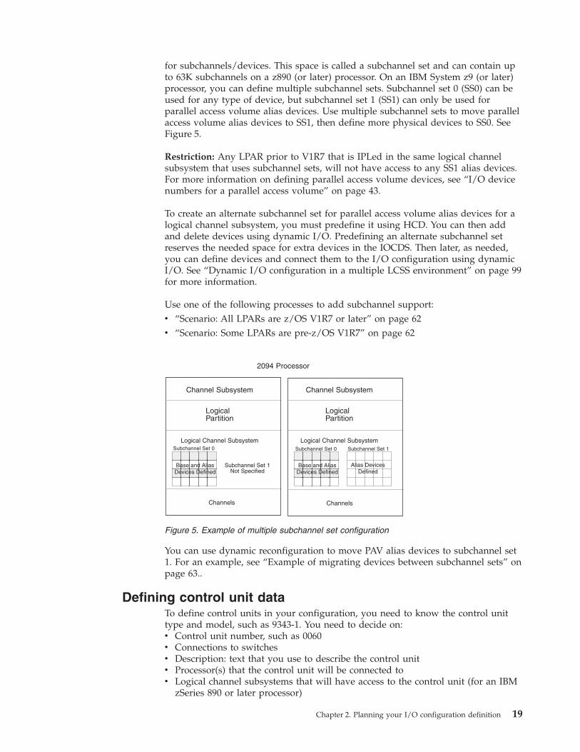
for subchannels/devices. This space is called a subchannel set and can contain upto 63K subchannels on a z890 (or later) processor. On an IBM System z9 (or later)processor, you can define multiple subchannel sets. Subchannel set 0 (SS0) can beused for any type of device, but subchannel set 1 (SS1) can only be used forparallel access volume alias devices. Use multiple subchannel sets to move parallelaccess volume alias devices to SS1, then define more physical devices to SS0. SeeFigure 5.
Restriction: Any LPAR prior to V1R7 that is IPLed in the same logical channelsubsystem that uses subchannel sets, will not have access to any SS1 alias devices.For more information on defining parallel access volume devices, see “I/O devicenumbers for a parallel access volume” on page 43.
To create an alternate subchannel set for parallel access volume alias devices for alogical channel subsystem, you must predefine it using HCD. You can then addand delete devices using dynamic I/O. Predefining an alternate subchannel setreserves the needed space for extra devices in the IOCDS. Then later, as needed,you can define devices and connect them to the I/O configuration using dynamicI/O. See “Dynamic I/O configuration in a multiple LCSS environment” on page 99for more information.
Use one of the following processes to add subchannel support:v “Scenario: All LPARs are z/OS V1R7 or later” on page 62v “Scenario: Some LPARs are pre-z/OS V1R7” on page 62
You can use dynamic reconfiguration to move PAV alias devices to subchannel set1. For an example, see “Example of migrating devices between subchannel sets” onpage 63..
Defining control unit dataTo define control units in your configuration, you need to know the control unittype and model, such as 9343-1. You need to decide on:v Control unit number, such as 0060v Connections to switchesv Description: text that you use to describe the control unitv Processor(s) that the control unit will be connected tov Logical channel subsystems that will have access to the control unit (for an IBM
zSeries 890 or later processor)
Channel Subsystem
LogicalPartition
Logical Channel Subsystem
Channels
Subchannel Set 0
Subchannel Set 1Not Specified
Channel Subsystem
LogicalPartition
Logical Channel Subsystem
Channels
Subchannel Set 0 Subchannel Set 1
Alias DevicesDefined
2094 Processor
Base and AliasDevices Defined
Base and AliasDevices DefinedBa
Dease evice
andes D
d AliDefin
iasned
BaDe
ase evice
andes D
d AliDefin
iasned
Figure 5. Example of multiple subchannel set configuration
Chapter 2. Planning your I/O configuration definition 19
v Information to attach the control unit to a channel path of the processor:– Channel path IDs– Link address– Unit address ranges that the control unit recognizes– Protocol– I/O concurrency level: classification of a control unit based on its ability to
concurrently operate and control the activity of attached devices withoutcausing loss of control or data.
– Logical address, which is known as the CUADD value
Defining I/O device dataTo define I/O devices in your configuration, you need to know the device typeand model, such as 3420-7. You need to decide:v The device number you want assigned to a device, for example, 0015. See
“Specifying an I/O device number” on page 42 for considerations.v Number(s) of the control unit(s) to which a device attaches.v Device parameters and features for defining a device to an operating system,
including whether the device supports dynamic configuration or whether a tapedevice is automatically switchable. See “Specifying I/O device parameters andfeatures” on page 46 for more information.
v For esoteric device groups (that you named in the EDT as part of definingoperating system data):– Which I/O devices you will include in each group– Which groups you want to make eligible for VIO. See “Defining devices as
virtual I/O (VIO) eligible” on page 61.v Any generic device types that you want to make eligible for VIO. See “Defining
devices as virtual I/O (VIO) eligible” on page 61.v Any changes you need to make to the device preference table for each EDT.v The I/O devices that you will allow z/OS to use as NIP consoles.
z/OS needs a console to initialize the system. The console can be a device thatyou identified as a nucleus initialization program (NIP) console through HCD.For each I/O configuration, you can specify through HCD a list of the devicesthat can be used as a NIP console. During system initialization, z/OS uses as theNIP console the first device in the list that is online and attached to the system.If your processor has the console integration feature, you can use the systemconsole to initialize the system, and you do not need to specify NIP consolesthrough HCD. For more information about the consoles that the operator uses toinitialize a system, see z/OS MVS Planning: Operations.
v Device parameters associated with the processor, such as unit address andpreferred channel path ID. This information includes whether you want tocontrol logical partition access to devices when logical partitions get accessthrough a shared channel path. If you do want to limit logical partition access,you specify that you want an explicit device candidate list when asked by HCD.See “Defining logical partition access to a channel path” on page 30.
Deciding about JES3 initialization stream checker dataConsider whether you need to create data that the JES3 initialization streamchecker will use.
During the JES3 initialization process, you must define to JES3 the devices thatJES3 manages. It is essential that the JES3 and MVS I/O configuration definitionsbe consistent. You can use the JES3 initialization stream checker to identify
20 z/OS V1R12.0 HCD Planning
inconsistencies in the JES3 and MVS I/O definitions. The JES3 initialization checkerlooks for logical errors in the JES3 initialization statements.
The JES3 initialization stream checker can test for I/O definition consistency only ifyou supply data about the MVS I/O configuration definition. HCD enables you towrite to a data set the MVS configuration data that the checker needs. You use thedata set as input when you run the checker. For more information about runningthe initialization stream checker, see z/OS JES3 Initialization and Tuning Guide.
To write the configuration data to the data set with HCD, you choose the “CreateJES3 Initialization Stream Data” option on the HCD Activate and ProcessConfiguration Data panel. On the HCD Create JES3 INISH Stream Checker Datapanel, you specify the following information:v Name of the data set that you created to contain the MVS configuration data to
be input to the JES3 initialization stream checkerv Identifier of the operating system configuration and EDT for which you want to
create the data set.
Understanding a sysplex configurationHCD offers you a single point of control for systems in a sysplex that includes acoupling facility for data sharing. A coupling facility is connected to the processorsthrough channels. With HCD you can:v Define the hardware and software configurations in a sysplexv Manage IOCDS and IPL attributes across a sysplexv Dynamically activate hardware and software configuration changes across a
sysplex.
This topic provides overview information about HCD definitions required withsystems in a sysplex that includes a coupling facility. It also describes using HCDto manage IOCDSs in a sysplex and configuring your tape devices in a sysplex.For information about how to dynamically activate configurations in a sysplex, see“Dynamically changing an I/O configuration in a sysplex” on page 87.
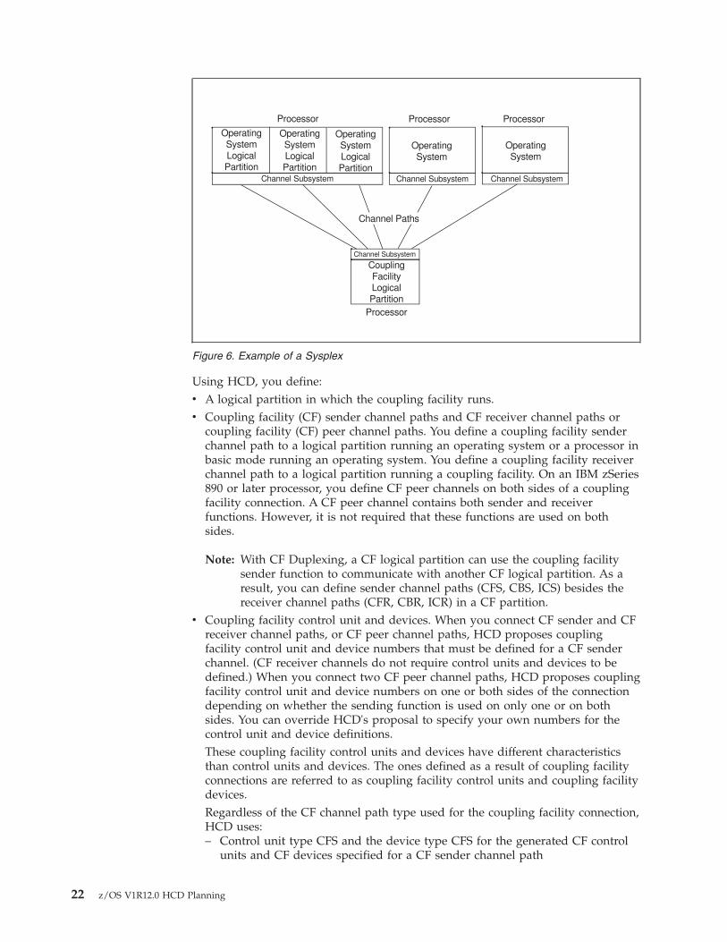
Defining coupling facility components in a sysplexA coupling facility is a special logical partition that runs the coupling facilitycontrol code (CFCC) and provides high-speed caching, list processing, and lockingfunctions in a sysplex. HCD enables you to specify whether a logical partition canbe a coupling facility, operating system, or either on certain processors. Youconnect the coupling facility logical partition to a processor through the couplingfacility channels as shown in Figure 6 on page 22.
Chapter 2. Planning your I/O configuration definition 21
Using HCD, you define:v A logical partition in which the coupling facility runs.v Coupling facility (CF) sender channel paths and CF receiver channel paths or
coupling facility (CF) peer channel paths. You define a coupling facility senderchannel path to a logical partition running an operating system or a processor inbasic mode running an operating system. You define a coupling facility receiverchannel path to a logical partition running a coupling facility. On an IBM zSeries890 or later processor, you define CF peer channels on both sides of a couplingfacility connection. A CF peer channel contains both sender and receiverfunctions. However, it is not required that these functions are used on bothsides.
Note: With CF Duplexing, a CF logical partition can use the coupling facilitysender function to communicate with another CF logical partition. As aresult, you can define sender channel paths (CFS, CBS, ICS) besides thereceiver channel paths (CFR, CBR, ICR) in a CF partition.
v Coupling facility control unit and devices. When you connect CF sender and CFreceiver channel paths, or CF peer channel paths, HCD proposes couplingfacility control unit and device numbers that must be defined for a CF senderchannel. (CF receiver channels do not require control units and devices to bedefined.) When you connect two CF peer channel paths, HCD proposes couplingfacility control unit and device numbers on one or both sides of the connectiondepending on whether the sending function is used on only one or on bothsides. You can override HCD's proposal to specify your own numbers for thecontrol unit and device definitions.These coupling facility control units and devices have different characteristicsthan control units and devices. The ones defined as a result of coupling facilityconnections are referred to as coupling facility control units and coupling facilitydevices.Regardless of the CF channel path type used for the coupling facility connection,HCD uses:– Control unit type CFS and the device type CFS for the generated CF control
units and CF devices specified for a CF sender channel path
Processor Processor Processor
OperatingSystemLogicalPartition
OperatingSystem
Channel Subsystem
Channel Paths
CouplingFacilityLogicalPartition
OperatingSystemLogicalPartition
OperatingSystemLogicalPartition
Channel Subsystem Channel Subsystem
Channel Subsystem
Processor
OperatingSystem
Figure 6. Example of a Sysplex
22 z/OS V1R12.0 HCD Planning
– Control unit type CFP and device type CFP for the generated control unitsand CF devices specified for each of the CF peer channel paths
When you make connections between coupling facility channel paths, a couplingfacility control unit and coupling facility devices are defined to represent theconnections in the channel subsystem connection to the coupling facility. Onecoupling facility control unit is defined for each coupling facility that a processorconnects to. For example, one control unit is defined when two logical partitionson a processor are connected to the same coupling facility partition. Two couplingfacility devices are defined for each coupling facility path connection using CFsender and CF receiver channel paths. Seven coupling facility devices are definedfor each connected CF peer channel path.
Coupling facility control units and devices are automatically defined by the CFsender-to-receiver or peer-to-peer connections that are established. You do not haveto use the “Define Control Unit Data” option that you use to define control unitsand you do not have to use the “Define Device Data” option that you use to defineI/O devices. See “Making changes to coupling facility devices and control units”on page 97 for information about changes to the coupling facility definitions.
The characteristics that distinguish coupling facility components are:v UIMs are not needed for coupling facility devicesv Coupling facility devices are not represented by UCBsv An EDT and dynamic allocation do not pertain to coupling facility devicesv You do not select a preferred channel path to a coupling facility devicev You do not vary coupling facility devices offlinev Channel measurement blocks (CMBs) do not apply to coupling facility devicesv You cannot specify a unit address for a coupling facility devicev The concept of logical versus physical control unit does not applyv You cannot specify a logical address for a coupling facility control unit.
Coupling facility (CF) channels can be defined as Intersystem Coupling (ISC)channels or as Integrated Cluster Bus (ICB) channels. The channel path types usedfor ISC channels are CFS for the coupling facility sender channel, CFR for thecoupling facility receiver channel, and CFP for the coupling facility peer channel.The channel path types used for ICB channels are CBS for the coupling facilitysender channel, CBR for the coupling facility receiver channel, and CBP for thecoupling facility peer channel.
For testing purposes, you can use a central processor complex (CPC) to simulatecoupling facility channels.
You do not define coupling facility channel paths, a coupling facility control unit,or coupling facility devices for the logical partitions that use ICMF. ICMFautomatically generates an appropriate configuration of integrated coupling facilitypaths, coupling facility control units, and coupling facility devices for the logicalpartitions to use.
With ICMF, if possible, avoid using the channel path identifiers, device numbers,or control unit numbers shown in Table 2 on page 24 for your I/O componentdefinitions. ICMF uses these numbers when it simulates the coupling facilitycomponents.
Chapter 2. Planning your I/O configuration definition 23
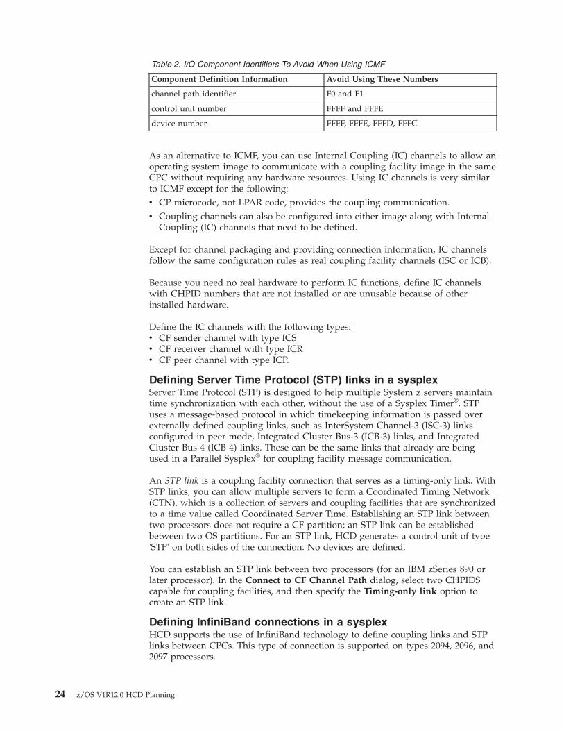
Table 2. I/O Component Identifiers To Avoid When Using ICMF
Component Definition Information Avoid Using These Numbers
channel path identifier F0 and F1
control unit number FFFF and FFFE
device number FFFF, FFFE, FFFD, FFFC
As an alternative to ICMF, you can use Internal Coupling (IC) channels to allow anoperating system image to communicate with a coupling facility image in the sameCPC without requiring any hardware resources. Using IC channels is very similarto ICMF except for the following:v CP microcode, not LPAR code, provides the coupling communication.v Coupling channels can also be configured into either image along with Internal
Coupling (IC) channels that need to be defined.
Except for channel packaging and providing connection information, IC channelsfollow the same configuration rules as real coupling facility channels (ISC or ICB).
Because you need no real hardware to perform IC functions, define IC channelswith CHPID numbers that are not installed or are unusable because of otherinstalled hardware.
Define the IC channels with the following types:v CF sender channel with type ICSv CF receiver channel with type ICRv CF peer channel with type ICP.
Defining Server Time Protocol (STP) links in a sysplexServer Time Protocol (STP) is designed to help multiple System z servers maintaintime synchronization with each other, without the use of a Sysplex Timer®. STPuses a message-based protocol in which timekeeping information is passed overexternally defined coupling links, such as InterSystem Channel-3 (ISC-3) linksconfigured in peer mode, Integrated Cluster Bus-3 (ICB-3) links, and IntegratedCluster Bus-4 (ICB-4) links. These can be the same links that already are beingused in a Parallel Sysplex® for coupling facility message communication.
An STP link is a coupling facility connection that serves as a timing-only link. WithSTP links, you can allow multiple servers to form a Coordinated Timing Network(CTN), which is a collection of servers and coupling facilities that are synchronizedto a time value called Coordinated Server Time. Establishing an STP link betweentwo processors does not require a CF partition; an STP link can be establishedbetween two OS partitions. For an STP link, HCD generates a control unit of type'STP' on both sides of the connection. No devices are defined.
You can establish an STP link between two processors (for an IBM zSeries 890 orlater processor). In the Connect to CF Channel Path dialog, select two CHPIDScapable for coupling facilities, and then specify the Timing-only link option tocreate an STP link.
Defining InfiniBand connections in a sysplexHCD supports the use of InfiniBand technology to define coupling links and STPlinks between CPCs. This type of connection is supported on types 2094, 2096, and2097 processors.
24 z/OS V1R12.0 HCD Planning
To define an InfiniBand connection, use channel path type 'CIB' to emulate acoupling connection in the Host Communication Adapter (HCA).
Reconfiguration of coupling facility receiver CHPIDsYou can reconfigure CF receiver CHPIDs to change the association between a z/OSimage and a coupling facility (CF) logical partition without the overhead of apower-on-reset (POR). An operator command configures the CHPID to a differentCF partition.
Reconfiguring CF receiver CHPIDs is intended for preplanned configurationchanges that require the movement of CF channel capacity. This function is alsouseful in recovery situations; you can, for example, move channel capacity fromlower priority work, such as test, to higher priority work, such as production.
There are restrictions on configuration definitions for reconfigurable CF receiverCHPIDs. The configuration rules for dedicated CF receiver CHPIDs, however, arenot changed.
To understand the reconfiguration restrictions, you need to understand what "samez/OS image" means in the context of CF sender CHPIDs. The definition dependson whether the CF sender CHPID being connected is a dedicated or reconfigurablepath, or a shared path:v Both dedicated and reconfigurable CF sender CHPIDs belong to the same z/OS
image if the CHPIDs have identical access lists. Any connects of these CF senderCHPIDs are made from the same z/OS image.
v Shared CF sender CHPIDs are treated as if they belong to the same z/OS imageif there is at least one partition in common to all the CF sender channels. Anyconnects of these shared CF sender CHPIDs are made from the same z/OSimage.
Restrictions: Reconfiguring CF receiver CHPIDs requires two CF partitions:v Source CF partition that had initial access to the CF receiver CHPID at
power-on-reset (POR)v Target CF partition that has access after CF receiver CHPID reconfiguration
The CF partition specified in the access list is the source CF, and the CF partitionspecified in the candidate list is the target CF.
The following restrictions apply:v When you define a reconfigurable CF receiver CHPID, specify only a single CF
partition, the source CF, in the access list and only a single CF partition, thetarget CF, in the candidate list.
v You can define reconfigurable and dedicated CF receiver CHPIDs in the sameCF partition:– You must define as dedicated any CF receiver CHPID initially accessed within
a target CF logical partition.– You can define as dedicated or reconfigurable any CF receiver CHPID in a
source CF logical partition as long as all connects from the same z/OS imageare to CF receiver CHPIDs that are either all dedicated or all reconfigurable.
v You must reconfigure both CF sender CHPIDs and CF receiver CHPIDs togetheras part of a planned reconfiguration. If you reconfigure them separately, resultsare unpredictable.
v All connects from the same z/OS image to CF receivers with the same access listmust have the same candidate list. All CF receiver CHPIDs that are connected
Chapter 2. Planning your I/O configuration definition 25
from the same z/OS image to the same source CF partition must bereconfigured to the same target CF partition.
v All connects from the same z/OS image to CF receivers with access lists that aredifferent from any previous connection must have candidate lists that aredifferent from any previous connection. All CF receiver CHPIDs that areconnected from the same z/OS image to different source CF partitions must bereconfigured to different target CF partitions.
v All connects from different z/OS images to CF receiver CHPIDs with the sameaccess list can have the same or different candidate lists. Not all CF receiverCHPIDs from the same source CF logical partition need to be reconfigured tothe same target CF logical partition.
v All connects from different z/OS images to CF receiver CHPIDs with differentaccess lists can have the same or different candidate lists. A target CF partitioncan have CF receiver CHPIDs reconfigured to it from many source CF partitions.
Reconfiguring coupling facility peer CHPIDsA CF peer channel path may specify both z/OS images and CF logical partitions inits access and candidate lists. You can define a CF peer channel path as dedicated,reconfigurable, shared, or spanned. For a dedicated CF peer channel path, you canspecify only one logical partition, running either an operating system image or acoupling facility. When you define a CF peer channel path as a reconfigurable,shared, or spanned, you can specify only one CF logical partition in its access listand one additional CF logical partition in its candidate list.
A coupling facility connection using CF peer channels must specify at least onez/OS image on one CF peer channel while the other CF peer channel must specifyat least one CF logical partition. It is possible for each CF peer channel path of theconnection to specify a CF logical partition.
With respect to the sender and receiver functions, the restrictions for reconfiguringCF peer channels in CF logical partitions are analogous to the CF receiver channelpath restrictions described previously.
Managing IOCDSs and IPL attributes across a sysplexHCD provides you with a single point of control for managing your I/Oconfiguration data sets (IOCDSs). On the HCD panels, processors are referred to asS/390 microprocessor clusters. You create IOCDSs and update IPL parameters foreach central processor complex (CPC) in a S/390 microprocessor cluster.
The Hardware Management Console consists of a hardware management consoleapplication (HWMCA) running on a PC and a LAN connected to the supportelement of each coupling facility and the support element of each CPC in an S/390microprocessor cluster.
Figure 7 on page 27 shows an example of support elements connected to aHardware Management Console.
26 z/OS V1R12.0 HCD Planning
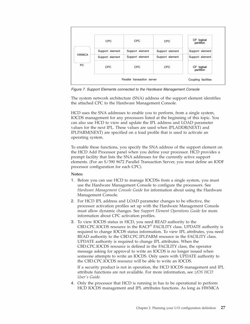
The system network architecture (SNA) address of the support element identifiesthe attached CPC to the Hardware Management Console.
HCD uses the SNA addresses to enable you to perform, from a single system,IOCDS management for any processors listed at the beginning of this topic. Youcan also use HCD to view and update the IPL address and LOAD parametervalues for the next IPL. These values are used when IPLADDR(NEXT) andIPLPARM(NEXT) are specified on a load profile that is used to activate anoperating system.
To enable these functions, you specify the SNA address of the support element onthe HCD Add Processor panel when you define your processor. HCD provides aprompt facility that lists the SNA addresses for the currently active supportelements. (For an S/390 9672 Parallel Transaction Server, you must define an IODFprocessor configuration for each CPC).
Notes:
1. Before you can use HCD to manage IOCDSs from a single system, you mustuse the Hardware Management Console to configure the processors. SeeHardware Management Console Guide for information about using the HardwareManagement Console.
2. For HCD IPL address and LOAD parameter changes to be effective, theprocessor activation profiles set up with the Hardware Management Consolemust allow dynamic changes. See Support Element Operations Guide for moreinformation about CPC activation profiles.
3. To view IOCDS status in HCD, you need READ authority to theCBD.CPC.IOCDS resource in the RACF® FACILITY class. UPDATE authority isrequired to change IOCDS status information. To view IPL attributes, you needREAD authority to the CBD.CPC.IPLPARM resource in the FACILITY class.UPDATE authority is required to change IPL attributes. When theCBD.CPC.IOCDS resource is defined in the FACILITY class, the operatormessage asking for approval to write an IOCDS is no longer issued whensomeone attempts to write an IOCDS. Only users with UPDATE authority tothe CBD.CPC.IOCDS resource will be able to write an IOCDS.If a security product is not in operation, the HCD IOCDS management and IPLattribute functions are not available. For more information, see z/OS HCDUser's Guide.
4. Only the processor that HCD is running in has to be operational to performHCD IOCDS management and IPL attributes functions. As long as HWMCA
CF logicalpartition
CF logicalpartition
HWMCASupport element
Support element Support element Support element
Support element Support element Support element
Support element
Parallel transaction server Coupling facilities
CPC
CPC CPC CPC
CPC CPC
PCCF logical
partitionCF logical
partition
Figure 7. Support Elements connected to the Hardware Management Console
Chapter 2. Planning your I/O configuration definition 27
and the support elements are operational, HCD can perform these functions onthe other support elements even if the processors attached to these supportelements are powered off.
Using automatic tape switchingWhen you configure your tape devices in a sysplex, you must consider whether tohave all your tape drives on one system, or whether you will spread them out. Youcan share tape devices across many systems, both with and without the need formanual intervention by the operator.
IBM offers the following ways for many systems to use the same tape devices:v A dedicated tape device, which is varied online to one system at a time. For a
second system to use that same device, an operator issues VARY commands(first VARY OFFLINE, then VARY ONLINE) to make the device available to thesecond system. In this information, tape devices are assumed to be dedicatedunless specified otherwise.
v An automatically switchable tape device, which can be online to more than onesystem at a time. For one system to use an automatically switchable tape device,then another system to use the same device, an operator does not have to enterany VARY commands. When the system selects that device for allocation to a jobstep, the device is at once both assigned to the specific system and allocated tothe job step. Automatically switchable tape devices require that the systems inthe sysplex communicate with each other with the ATS STAR method availablewith z/OS V1R2 and later.
You can define a tape device as automatically switchable through HCD. Forinformation about automatic tape switching, including benefits and set-uprecommendations, see z/OS MVS System Commands.
Preparing for automatic tape switchingPreparing for automatic tape switching requires you to:v Decide how many automatically switchable devices to define; see “Deciding
how to use automatically switchable devices.”v Define tape devices as automatically switchable; see “Defining a tape device as
automatically switchable” on page 48.
Deciding how to use automatically switchable devices: The system programmerdetermines the appropriate balance of dedicated devices and automaticallyswitchable devices to meet the installation's needs. Factors that affect the decisionare:v The number of systems in the sysplexv The number of devices that are eligible for automatic tape switching. Automatic
tape switching requires “assign-capable” tape devices, such as 3490 or 3480 tapedrives.
v The systems' workloads and the number of jobs requiring tape devices.v Whether the installation has other ways to manage devices, such as JES3 or a
vendor product.
Generally, tape devices that are already available to multiple systems and usedperiodically but not constantly are candidates for being defined as automaticallyswitchable. These devices can be used more efficiently when available to any or allsystems in the sysplex.
28 z/OS V1R12.0 HCD Planning
You might have good reasons to have a mixture of dedicated and automaticallyswitchable devices in an installation. Consider the following example that shows agood way of splitting up your tape devices. In our example, a computingenvironment includes:v A System z9® processor that runs the company's large batch applicationsv An S/390 microprocessor cluster that runs a CICS® OLTP workloadv A coupling facility that connects the System z9 processor and the S/390
microprocessor clusterv 60 3490 tape devices
Because of their heavy demand for storage, the batch jobs on the System z9processor need the majority of the tape devices. The CICS applications haveoccasional and short-term need for tape devices. Rather than having an operatorvary the tape devices online and offline as the systems' requirements for tapedevices change, divide the tape devices so that the batch work and the CICSworkload use the tape devices as follows:v 50 of the devices are dedicated to the batch work on the System z9 processor.v 10 of the devices are automatically switchable across the systems in the S/390
microprocessor cluster.
Operational considerations for automatic tape switching: The operations staff isresponsible for varying the automatically switchable devices online. They also mustrespond to messages that describe problems caused during automatic tapeswitching.
For considerations, see z/OS MVS System Commands, which describes how to:v Define automatically switchable devicesv Display information about automatically switchable devicesv Respond to automatic tape switching events
Defining shared channel pathsThis topic provides background information that is helpful if you are definingshared channel paths in your I/O configuration.
Multiple Image Facility (MIF) capability enables logical partitions to share channelpaths, such as ESCON, FICON, and coupling facility sender channel paths,between logical partitions within a processor complex. If a processor complex hasMIF capability, and is running in LPAR mode, all logical partitions can access thesame shared channel paths, thereby reducing the number of required physicalconnections. In contrast, if a processor complex does not have MIF capability, alllogical partitions must use separate channel paths to share I/O devices.
Figure 8 on page 30 compares three unshared channel paths to a single sharedchannel path. In processor complex A, three logical partitions can access an I/Odevice through three unshared channel paths. In processor complex B, which hasMIF capability, three logical partitions can access an I/O device through a singleshared channel path.
Chapter 2. Planning your I/O configuration definition 29
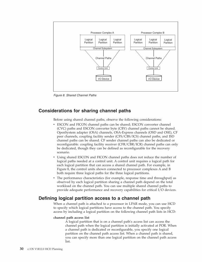
Considerations for sharing channel paths
Before using shared channel paths, observe the following considerations:v ESCON and FICON channel paths can be shared; ESCON converter channel
(CVC) paths and ESCON converter byte (CBY) channel paths cannot be shared.OpenSystem adapter (OSA) channels, OSA-Express channels (OSD and OSE), CFpeer channels, coupling facility sender (CFS/CBS/ICS) channel paths, and ISDchannel paths can be shared. CF sender channel paths can also be dedicated orreconfigurable. coupling facility receiver (CFR/CBR/ICR) channel paths can onlybe dedicated, though they can be defined as reconfigurable for the recoveryscenario.
v Using shared ESCON and FICON channel paths does not reduce the number oflogical paths needed at a control unit. A control unit requires a logical path foreach logical partition that can access a shared channel path. For example, inFigure 8, the control units shown connected to processor complexes A and Bboth require three logical paths for the three logical partitions.
v The performance characteristics (for example, response time and throughput) asobserved by each logical partition sharing a channel path depend on the totalworkload on the channel path. You can use multiple shared channel paths toprovide adequate performance and recovery capabilities for critical I/O devices.
Defining logical partition access to a channel pathWhen a channel path is attached to a processor in LPAR mode, you can use HCDto specify which logical partitions have access to the channel path. You specifyaccess by including a logical partition on the following channel path lists in HCD:
channel path access listA logical partition that is on a channel path's access list can access thechannel path when the logical partition is initially activated at POR. Whena channel path is dedicated or reconfigurable, you specify one logicalpartition on the channel path access list. When a channel path is shared,you can specify more than one logical partition on the channel path accesslist.
Processor Complex A
LogicalPartition
Channel Subsystem
LogicalPartition
LogicalPartition
Channel Paths
I/O Device
Control Unit
Processor Complex B
LogicalPartition
Channel Subsystem
LogicalPartition
LogicalPartition
Channel Paths
I/O Device
Control Unit
Figure 8. Shared Channel Paths
30 z/OS V1R12.0 HCD Planning
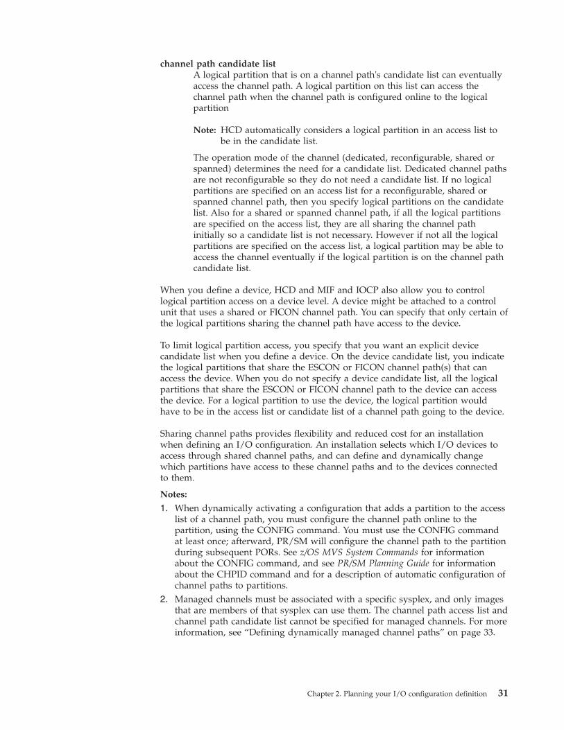
channel path candidate listA logical partition that is on a channel path's candidate list can eventuallyaccess the channel path. A logical partition on this list can access thechannel path when the channel path is configured online to the logicalpartition
Note: HCD automatically considers a logical partition in an access list tobe in the candidate list.
The operation mode of the channel (dedicated, reconfigurable, shared orspanned) determines the need for a candidate list. Dedicated channel pathsare not reconfigurable so they do not need a candidate list. If no logicalpartitions are specified on an access list for a reconfigurable, shared orspanned channel path, then you specify logical partitions on the candidatelist. Also for a shared or spanned channel path, if all the logical partitionsare specified on the access list, they are all sharing the channel pathinitially so a candidate list is not necessary. However if not all the logicalpartitions are specified on the access list, a logical partition may be able toaccess the channel eventually if the logical partition is on the channel pathcandidate list.
When you define a device, HCD and MIF and IOCP also allow you to controllogical partition access on a device level. A device might be attached to a controlunit that uses a shared or FICON channel path. You can specify that only certain ofthe logical partitions sharing the channel path have access to the device.
To limit logical partition access, you specify that you want an explicit devicecandidate list when you define a device. On the device candidate list, you indicatethe logical partitions that share the ESCON or FICON channel path(s) that canaccess the device. When you do not specify a device candidate list, all the logicalpartitions that share the ESCON or FICON channel path to the device can accessthe device. For a logical partition to use the device, the logical partition wouldhave to be in the access list or candidate list of a channel path going to the device.
Sharing channel paths provides flexibility and reduced cost for an installationwhen defining an I/O configuration. An installation selects which I/O devices toaccess through shared channel paths, and can define and dynamically changewhich partitions have access to these channel paths and to the devices connectedto them.
Notes:
1. When dynamically activating a configuration that adds a partition to the accesslist of a channel path, you must configure the channel path online to thepartition, using the CONFIG command. You must use the CONFIG commandat least once; afterward, PR/SM will configure the channel path to the partitionduring subsequent PORs. See z/OS MVS System Commands for informationabout the CONFIG command, and see PR/SM Planning Guide for informationabout the CHPID command and for a description of automatic configuration ofchannel paths to partitions.
2. Managed channels must be associated with a specific sysplex, and only imagesthat are members of that sysplex can use them. The channel path access list andchannel path candidate list cannot be specified for managed channels. For moreinformation, see “Defining dynamically managed channel paths” on page 33.
Chapter 2. Planning your I/O configuration definition 31

Processors communicating through shared ESCON or FICONchannel paths
An ESCON channel-to-channel (CTC) channel path has an ESCON CTC connectionat one end, and either an ESCON (CNC) or FICON (FCV) channel connection atthe other end. For any two processor complexes to communicate through anESCON channel path, the ESCON CTC connection can be at either processorcomplex.
Processors at the IBM zSeries 900 level and later exploit the FICON capability toprovide channel-to-channel host communication between processors. FICON CTC(FCTC) provides CTC communication at a higher bandwidth and with greaterconnectivity than with ESCON CTC. An FCTC connection to a processor earlierthan IBM zSeries 900 (G5/G6 processors) is only possible if one of the two FCchannel paths that perform the FCTC connection is defined on an IBM 2064 orlater CPC.
ESCON or FICON CTC connections that are defined through a switch can bevalidated and reported in HCD (see the CTC Connection Report in z/OS HCDUser's Guide. When using HCM, a separate dialog is provided for defining CTCconnections. See z/OS and z/VM HCM User's Guide.
Using ESCON CTC connectionsTo communicate from a processor complex to a logical partition through anESCON CTC channel path attached to a shared ESCON channel path, you mustspecify the logical address of the ESCON CTC (SCTC) control unit that representsthe target system.
As shown in Figure 9 on page 33, the logical address is the number of the targetlogical partition. As explained in z/OS HCD User's Guide, you can specify partitionnumbers when defining partitions, and you can specify these partition numbers asthe logical address for a CTC control unit.
For more information about communicating through ESCON CTC channel paths,see ESCON and FICON CTC Reference.
In the following example LP 1 has been assigned partition number 1, LP 2 hasbeen assigned partition number 2, and so on.
32 z/OS V1R12.0 HCD Planning
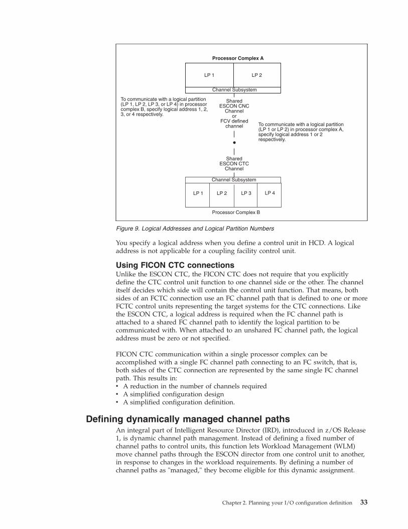
You specify a logical address when you define a control unit in HCD. A logicaladdress is not applicable for a coupling facility control unit.
Using FICON CTC connectionsUnlike the ESCON CTC, the FICON CTC does not require that you explicitlydefine the CTC control unit function to one channel side or the other. The channelitself decides which side will contain the control unit function. That means, bothsides of an FCTC connection use an FC channel path that is defined to one or moreFCTC control units representing the target systems for the CTC connections. Likethe ESCON CTC, a logical address is required when the FC channel path isattached to a shared FC channel path to identify the logical partition to becommunicated with. When attached to an unshared FC channel path, the logicaladdress must be zero or not specified.
FICON CTC communication within a single processor complex can beaccomplished with a single FC channel path connecting to an FC switch, that is,both sides of the CTC connection are represented by the same single FC channelpath. This results in:v A reduction in the number of channels requiredv A simplified configuration designv A simplified configuration definition.
Defining dynamically managed channel pathsAn integral part of Intelligent Resource Director (IRD), introduced in z/OS Release1, is dynamic channel path management. Instead of defining a fixed number ofchannel paths to control units, this function lets Workload Management (WLM)move channel paths through the ESCON director from one control unit to another,in response to changes in the workload requirements. By defining a number ofchannel paths as "managed," they become eligible for this dynamic assignment.
Channel Subsystem
Processor Complex A
Channel Subsystem
LP 4LP 3LP 2LP 1
Processor Complex B
SharedESCON CNC
Channelor
FCV definedchannel
SharedESCON CTC
Channel
To communicate with a logical partition(LP 1, LP 2, LP 3, or LP 4) in processorcomplex B, specify logical address 1, 2,3, or 4 respectively.
To communicate with a logical partition(LP 1 or LP 2) in processor complex A,specify logical address 1 or 2respectively.
LP 1 LP 2
Figure 9. Logical Addresses and Logical Partition Numbers
Chapter 2. Planning your I/O configuration definition 33
Dynamic channel path management works in two modes: goal mode and balancemode. In goal mode, available only when WLM is running in goal mode, dynamicchannel path management will manage the channel paths to best meet theperformance goals of the most important work, even at the expense of lessimportant work, if necessary. In balance mode, available whether WLM is runningin goal mode or compatibility mode, dynamic channel path management willsimply attempt to balance the responsiveness of all the DASD subsystems, movingdynamic channels as needed.
Dynamic channel path management is allowed only on an IBM 2064 (IBM zSeries900) or later CPC. HCD ensures that no managed channel paths are connected to aCPC prior to this level.
IRD allows an installation to group logical partitions that are resident on the samephysical server, and in the same sysplex, into an “LPAR cluster.” This givesWorkload Management the ability to manage resources, both processor and DASDI/O, not just in one single image but across the entire cluster of logical partitions.To use dynamic channel path management, the CPC can be running in either basicor LPAR mode. In basic mode, a coupling facility is not needed, as there will be nological partitions grouped together in an LPAR cluster. In LPAR mode, a couplingfacility is required if you wish to use dynamic channel path management in anylogical partition containing a system that is a member of a multisystem complex(even if the logical partition is the only member of that sysplex on this CPC). Youdo not need a coupling facility if all the logical partitions are running inXCFLOCAL or MONOPLEX mode.
Attention: Dynamic channel path management supports only non-synchronouscontrol units, such as the Enterprise Storage Server®. A non-synchronous controlunit transfers data with the host directly to and from the control unit cache. It doesnot support synchronous control units, nor control units that are synchronous onoccasion, such as the 3990. The 3990 is a non-synchronous control unit most of thetime, but there are situations in which it will transfer data to or from the devicedirectly. Dynamic channel path management supports only 100% non-synchronouscontrol units.
The IBM Redbook z/OS Intelligent Resource Director (SG24-5952) providesinformation about choosing the appropriate channels and control units for dynamicchannel path management. The installations most likely to benefit are thefollowing:v Installations approaching the 256 channel limit per CPC (or 256 per logical
channel subsystem on an IBM zSeries 890 or later processor)
Logical LogicalPartition Partition
Channel Subsystem Channel Subsystem
Logical LogicalPartition Partition
Logical LogicalPartition Partition
Channel PathsChannel Paths
(after adjustment)
I/O Device I/O DeviceI/O Device I/O DeviceI/O Device I/O Device
Control Unit Control UnitControl Unit Control UnitControl Unit Control Unit
Figure 10. Dynamic Channel Path Management
34 z/OS V1R12.0 HCD Planning
v Smaller installations that do not have sufficient technical resources to design andmonitor DASD subsystems
v Installations that experience large variations in channel utilization at differenttimes of day
v Installations where the highest possible availability is an absolute requirementv Installations with a large number of control units, and multiple control units, per
channelv Installations with a large number of EMIF channels.
After you have selected the appropriate channels and control units for dynamicchannel path management, there are two HCD definitions that will need to bechanged: the channel definitions and the control unit definitions.
To define a channel as being managed, you must specify YES in the “Managed”field on the “Add Channel Path” HCD panel. You must also specify a dynamicswitch (in this case, the ESCON director) to which the channel is attached. It isrecommended that you also specify the entry switch ID and entry port so thatHCD can do consistency checking.
If you are running in LPAR mode, you must also define the name of the LPARcluster to which a logical partition must belong in order to have this channel in itsconfiguration. Specify this name in the “I/O Cluster” field. Finally, you must alsodefine this channel as being shared. Note that unlike traditional shared channelswhich potentially can be shared by all logical partitions on a CPC, managedchannels can only be shared by logical partitions in the same LPAR cluster.
To define a control unit as managed, you must make changes to its definition inthe “Add Control Unit” HCD panel. Whereas non-managed channel paths(otherwise called “static” channel paths) are defined through the CHPID number, amanaged path is defined by specifying an asterisk (“*”). The number of asterisksyou specify will limit the number of managed channel paths per CPC (or managedchannel paths per logical channel subsystem on an IBM zSeries 890 or laterprocessor). The total number of non-managed and managed channel paths perCPC (or managed channel paths per logical channel subsystem) cannot exceed 8.On an IBM zSeries 890 or later processor, you must define the managed channelpaths to the control unit in each logical channel subsystem.
Attention: You must define at least one non-managed channel path (which mustbe defined as shared) per control unit.
The control unit must be attached to a switch (in this case, an ESCON director)which in turn must be attached to managed channels.
See the z/OS HCD User's Guide for more information on using these panels todefine managed channels and control units.
Defining spanned channel pathsThis topic provides background information that is helpful if you are definingspanned channel paths in your I/O configuration.
A shared channel path can only be shared by partitions in a single logical channelsubsystem. In contrast, a spanned channel path is one that can be used bypartitions in more than one logical channel subsystem. You must use the same
Chapter 2. Planning your I/O configuration definition 35
CHPID value across all logical channel subsystems sharing the same spannedchannel. However, logical channel subsystems that do not share a spanned channelcan use that CHPID for other channels.
For more information, see “Dynamic I/O configuration in a multiple LCSSenvironment” on page 99.
Considerations for spanning channel pathsBefore using spanned channel paths, you need to consider the following:v Spanned CHPIDs still use access and candidate control lists to restrict access
within the logical channel subsystem.v Spanning reduces the number of channels that can be used. For example, on an
IBM zSeries 890 or later processor, you can have up 512 channels available ifyou define two logical channel subsystems. However, each logical channelsubsystem that has access to the spanned channel is using one of those 512CHPIDs. So, if you have not defined any spanned channels, you have 512channels available. If you define one channel as spanned across these 2 logicalchannel subsystems, you'll have only 511 channels available (512 - 2 usedCHPIDs + 1 spanned channel). If you span all of your channels across all ofyour logical channel subsystems, you'll have 256 CHPIDs.
v Not all channel types can be defined as spanned. On a z990 processors with thepre-May 2004 version of LIC, only IQD and Internal Coupling peer channels canbe defined as spanned. On a system at with HCD APAR OA03689 appliedrunning on a z990 or z890 processor, you can span the following channels:– Internal channels: ICP and IQD– Coupling facility peer and sender channels: CBP, CFP, CBS, and CFS– OSA channels: OSC, OSD, and OSE– Fibre channels: FC, FCP
v Managed channels cannot be defined as spanned.
Creating over-defined channel pathsFor an IBM zSeries 890 or later processor, you can define a channel path that is notphysically installed on the machine. This is called an over-defined channel path.You might do this if:v You want to migrate from a processor with more channels defined than the
target z890 or later processor.v You want to prepare your configuration for future channel card upgrades.
To distinguish an over-defined channel path from a physically installed one, usethe character "*" for the PCHID value when creating it. An over-defined CHPIDmust adhere to all validation rules, but is not recognized when you use the HCDBuild IOCDS function to create and download an IOCDS. In addition, they are notincluded:v In the IOCP statementsv In the CONFIGxx parmlib memberv During a dynamic activation
If a control unit contains only over-defined channel paths, the entire control unit,including any attached devices, is omitted from the configuration to be activated.
When you later physically install an over-defined channel path, you must edit theCHPID and replace the "*" value with a valid PCHID. You must do this first evenif you are going to use the CHPID mapping tool to assign the correct PCHIDvalue.
36 z/OS V1R12.0 HCD Planning
FICON channelsFICON (fibre connection) channels increase the capacity of the channel subsystem;each FICON channel can replace up to eight ESCON channels.
Channel path definitionsYou can define Fibre Channels in two ways:v The FCV (Fibre Channel) channel that uses a FICON Bridge offers a migration
path for ESCON CNC channels. Using the FICON Bridge Feature on the9032-005 ESCON Director, you can attach ESCON devices to the FCV channel.An FCV channel path occupies eight port addresses on the switch. To model theFCV bridge within HCD, consider the following. Whenever you connect aneligible port address to an FCV channel path, you must set all other portaddresses occupied by the FCV bridge to uninstall.
v The FC (Fibre Channel) channel requires a FICON interface at the control unit.FC channels can be attached directly to a control unit (point-to-point) or througha Fibre Channel (FC) switch.
Dynamic activationThere are no restrictions on dynamically activating an IODF that defines FCV orFC channel paths.
Migrating to FICON channelsBoth HCD and HCM offer migration functions you can use to convert CNCchannel paths to FCV channel paths, or to convert ESCON attachments (CNC orFCV) on the control unit to FICON attachments (FC).
Migrating from CNC to FCV channel pathsThe HCM migration function includes three utilities. These utilities provide theability to convert the CHPID type from CNC to FCV, to move ESCON portattachments effectively on the ESCON director, and to aggregate CNC CHPIDsonto an FCV CHPID.
The HCD migration function includes two dialogs, described in the followingprocedure for converting CNC channel paths to FCV channel paths. The procedureassumes that you have already decided which CNC CHPIDs you want to convergeto a single FCV channel path and which ESCON director ports you will use for theFICON Bridge feature card.
The FICON Bridge feature occupies eight contiguous port addresses on the ESCONdirector, starting with port address x4 or xC. HCD requires you to connect the FCVchannel path to the first port address and set the following seven port addresses touninstalled.
After you have completed your planning, take the following steps:1. Free the ports used by the FICON Bridge feature card.
Disconnect the ports to be freed from the connecting units and connect them toa target port. At the same time, change the corresponding logical definition(such as link address or dynamic switch). Depending on your configuration,this step includes:v Moving CHPIDs that are connected to either port to another (free) port, and
possibly to another switch, by updating the entry switch/entry port data inthe channel path definition. When you move the channel path to a new
Chapter 2. Planning your I/O configuration definition 37
switch, you must also change the dynamic switch, and move the connectedcontrol units to the new switch as well.
v Moving control units that are connected to either port to another (free) port,and possibly to another switch, by updating the connected switch/port datain the control unit definition. You must also change the link address. Whenyou move the control unit to a new switch, you can move the connectedchannel paths to the new switch as well, and update the channel pathsaccordingly.
v Moving switch-switch connections to another free port. On the switch portlist, disconnect the switch from the port and connect it to another port. Tomove a switch-switch connection, you might need to change the link addresson control units that are accessed through a dynamic connection to the portto be freed, and move related channel path ports and control unit ports.
To perform this step in HCD, select the Move Ports action from the Switch Listpanel.
2. Change the switch matrixes to match the changed connections.If you are moving ports on the same switch, using the Port Move dialog, HCDautomatically updates the switch configuration. If you are moving portsbetween different switches, you must update the switch configuration(s) of thetarget switch.
3. Define the FCV channel path.If the channel path you want to converge to the FCV channel path is alreadydefined with a CNC CHPID, change the CHPID type from CNC to FCV.If a channel path is already defined with the ID selected for the FCV CHPID,and you cannot or should not aggregate this CHPID to the FCV channel path,change the ID of the existing channel path.Defining an FCV channel path might require you to change the IDs of otherchannel paths on the same channel card to conform to channel packaging rules.
4. Connect the FCV channel path to the FCV entry port.There is an entry port prompt on the Define Channel Path panel and on theChange Channel Path panel. This prompt shows the free ports on the entryswitch, that are eligible to connect to FCV channel paths. For a switchconfiguration with an FCV channel connection, the following rules apply:v The FCV port must not have a dedicated connection defined.v If other FCV channel paths are connected to other ports, defining dynamic
connections between any two of these ports is prohibited.5. Aggregate other CNC channels to the FCV CHPID.
To aggregate other CNC channel paths to the FCV channel path, you must (1)disconnect the control units connected to the CNC channel path from the CNCCHPID, then (2) connect the control units to the FCV CHPID.Depending on the access and candidate lists of the FCV channel path and theCNC channel path to be converged, you might have to update the devicecandidate lists. For example, the target FCV CHPID might be defined asshared, and the CNC channel path to be converged might be defined asdedicated or reconfigurable.If the devices connected to the channel paths that are aggregated have apreferred CHPID defined, you must update the preferred CHPID.To perform this step in HCD, proceed as follows:v On the Channel Path list, select the FCV channel path and apply the
AGGREGATE CHPID action.
38 z/OS V1R12.0 HCD Planning
v On the Aggregate CHPID dialog, you can specify one CHPID at a time to beaggregated to the selected FCV channel path. Use the prompt to see thechannel paths that are eligible for the aggregation. For conditions that mustbe met for a CHPID to be eligible for the aggregation, see the HCD onlinehelp.
v Set the ports following the FCV entry port, the ports that the FICON Bridgefeature card will use, to uninstalled. If necessary, disconnect the aggregatedCNC channel paths from the switch to free these ports.
Migration from CNC or FCV to FC channel paths on the controlunitYou can seamlessly migrate from CNC or FCV to FC channel path attachments onthe control unit (for example, on an ESS 2105 Control Unit) without varying thedevices offline. You do this by the following steps:1. Dynamically add an FC channel path to the existing list of channel paths that
includes an ESCON channel path on the same (logical) control unit.2. Configure the FC channel path online. The system routes the I/O requests via
either the ESCON or the FICON channel attachments.3. Configure the CNC/FCV channel paths offline so that I/Os are now directed
via the FC channel path.4. Dynamically delete the CNC/FCV channel paths.
With some restrictions, you can intermix ESCON and FICON channels on the samelogical control unit. HCD supports the ESCON/FICON channel intermixture onthe control unit according to the following rules:v Intermixing FC channels with CNC and FCV channel paths should be
temporary, and done only for migration purposes. This mixture is notrecommended for production.
v Both the processor model and the control unit type must support the mixture ofESCON and FICON channel paths.
v If a control unit contains a mixture of CNC/FCV and FC channel paths, it isregarded as an ESCON control unit and validated according to the rules forESCON control units, such as attachment limits.
v If a control unit attaches only to FC channel paths, it is regarded as a FICONcontrol unit and validated according to the FICON control unit rules.
To determine the level to which your control units and devices supportintermixing, see their device planning manuals. For those control units that dosupport intermixing, please consult their performance white papers for guidanceon how to best configure channels from a performance perspective. To improve thebalance of workload across channels in an intermixed environment, IBMrecommends that you alternate ESCON (CNC and FCV) and FICON (FC) channelpaths in the control unit using the following patterns:v For 6 ESCON and 2 FICON, use a sequence of E, E, E, F, E, E, E, Fv For 4 ESCON and 4 FICON, use a sequence of E, F, E, F, E, F, E, Fv For 2 ESCON and 6 FICON, use a sequence of E, F, F, F, E, F, F, F
Open Systems Adapter ChannelsOpen Systems Adapter (OSA) channels allow:v Direct connection of LANs using the Queued Direct I/O (QDIO) architecturev Connection of LANs using non-QDIO architecturesv Attachment of TN3270E emulators for channels running the non-SNA DFT
protocol (OSA-ICC)
Chapter 2. Planning your I/O configuration definition 39
v Communication between a host OS partition using Channel Data Link Control(CDLC) and the NCP emulation on Linux® using QDIO.
HCD supports the following OSA channel path types to use the OSA supportfacility:v OSA QDIO channels (type OSD) are used for all LAN protocols that are
supported by OSA features that use QDIO architecture.v OSA non-QDIO channels (type OSE) are used for all LAN protocols that are
supported by OSA features that use non-QDIO architecture.v OSA ICC channels (type OSC) are use for TN3270E emulators. OSA-ICC is a
replacement of the 2074 Console Support Controller and local, non-SNA 3174control units.
v OSA NCP channels (type OSN) are used as replacement for ESCON channelcommunication between a host OS partition or VM guest (running VTAM® orTPF) and an SNA based 374x Network Control Program (NCP). The NCPfunction is emulated in Linux through the Communication Controller for Linux(CCL) on zSeries.
For more information about OSA channels, see System z10, System z9 and zSeriesOSA-Express Customer's Guide and Reference or the zSeries IOCP User's Guide,SB10-7037.
Defining special devices and special secondary devicesYou can use HCD to define special devices and special secondary devices. A specialdevice is one that is defined in the alternate subchannel set (not subchannel set 0).A special secondary device is a Peer-to-Peer Remote Copy (PPRC) secondary devicethat is defined in the alternate subchannel set.
By placing devices in the alternate subchannel set, you can keep some devicenumbers free for later use. For example, you might choose to define a fixed blockaccess (FBA) device, such as 3370, as a special device.
Unlike traditional devices, special devices and special secondary devices:v Are not included in the system's eligible device table (EDT)v Cannot be allocated through JCL or the DYNALLOC macrov Cannot be varied online or offline by the operator.
Special devices and special secondary devices use the default MIH setting for theirdevice classes. You cannot change the MIH interval for these devices through theMVS command SETIOS or through parmlib.
Special devices and special secondary devices are accessible only to authorizedprograms through the UCBSCAN and UCBLOOK macros. For more information,see z/OS MVS Programming: Authorized Assembler Services Reference SET-WTO.
Defining a special device (3390S)A device is considered special if it is defined in the alternate subchannel set. InHCD panels, a special device is shown as device type "3390S".
Observe the following considerations for a special device:v The device is considered to be offline and in-use by the system.v The IBM-provided DASD Error Recovery Procedure (ERP) is bypassed for an
application that uses the device.
40 z/OS V1R12.0 HCD Planning
v The event notification facility (ENF) does not issue an event code to indicate theonline or offline status of the device.
v To unbox a boxed special device, you can use the IOSODS service, that is:IOSODS OFF, then IOSODS ON.
Defining a special secondary device (3390D)You can place PPRC secondary devices (or special secondary devices) in the alternatesubchannel set and use the SWAP command to dynamically switch the devicesconcurrent to the applications using them. In HCD panels, a special secondarydevice is shown as device type "3390D".
For special secondary devices, observe the following considerations:v MIH values are not exchanged during a swap.v IPL and IODF devices cannot have secondaries in subchannel set 1.v The devices are configured to come up offline.v To unbox these devices, use the VARY PATH,ONLINE command.
For PPRC device pairs, observe the following considerations:v The four-digit device numbers for primary and secondary devices must match.v The associated primary device must be defined as a 3390B and have the same
attributes as the secondary device.v It is best to add or delete PPRC pairs at the same time, in a non-swapped
configuration.
Defining IQD CHPIDs and device typesHiperSockets™ is defined as a channel connection with a channel path type IQD.The IQD (Internal Queued Direct Communication) channel type allowscommunication between logical partitions on a single CPC and provides highspeed, low latency access to data. Support for IQD is available on IBM zSeries 900and later processors with z/OS Communications Server.
Define the IQD CHPIDs to HCD along with the control units (type IQD) anddevices (type IQD) that reside on them. Note that the control units and devicesdefined to either of these channel paths do not represent real I/O devices but datain a TCP/IP stack.
For an IQD channel path type, the maximum frame size to be used for IQDIOrequests on that channel path must be specified. Valid maximum frame sizessupported are 16K (default), 24K, 40K, and 64K. See z/OS Communications Server: IPConfiguration Guide for further information.
The following configuration rules apply for the IQD CHPID type:v On an IBM zSeries 890 or later processor, up to 16 IQD CHPIDs can be defined
per CPC and can be spanned across all logical channel subsystems and sharedamong all LPARs needing the function.
v On processors prior to the z890 or z990, you can define up to four IQD CHPIDsper CPC, to be shared among all LPARs needing the function. IQD CHPIDnumbers can range from X'00' to X'FF'.
v You can define up to 64 control units on each IQD CHPID. If more than onecontrol unit is defined for an IQD channel path, a logical address is required foreach control number. Control unit logical addresses can range from X'0' to X'F'.
Chapter 2. Planning your I/O configuration definition 41
v Up to 256 devices may be connected to an IQD control unit. The minimum valueis 3. HCD has a default of 10 devices per control unit.Up to 256 devices can beconnected to an IQD control unit. The minimum value is 3. HCD has a defaultof 10 devices per control unit.The maximum number of IQD devices that can be brought online at one timeper z/OS image is 1023; however, because the z/OS Communications Serveruses only a maximum of 10 online devices per IQD control unit for theHiperSockets function and you can define only 16 IQD CHPIDs per CPC, thenumber of usable devices per z/OS image is restricted to 160. Use caution whendefining more than 1023 IQD devices. Because of the IOS device initializationalgorithms, following an IPL, it is unpredictable which devices the system placesonline and which devices will be offline. When the 1023 device limit is reached,your attempts to issue VARY online commands for additional IQD devices arerejected with messages IOS577I and IOS579E. To bring additional IQD devicesonline, you must first VARY offline devices that were previously online. Toidentify which devices were not brought online, use the D M=CONFIG(xx)command.
v The total number of HSA subchannels for all IQD devices cannot exceed:– 3072 valid HSA subchannels on a processor prior to the IBM zSeries 890.– 12,288 valid HSA subchannels on an IBM zSeries 890 or later processor.
Restriction: You can define up to 256 IQD devices, but you cannot bring them allonline simultaneously. The number of IQD devices you can bring online at onetime is 160.
Specifying an I/O device numberThis topic describes considerations for specifying a device number when youdefine an I/O device to your configuration.
A device number is the number you assign to identify a device in HCD. You assigna device number to each device to identify it in the configuration. A device numbermay be any hexadecimal number from X'0000' to X'FFFF'.
When you specify coupling facility channel path connections, HCD defines controlunits and devices to attach to the CF sender or peer channel. HCD assigns to eachdevice a device number, which you can override. When assigning the devicenumber, HCD searches to use the highest available number starting with FFFF andcontinuing in descending order. You might want to avoid assigning the higherrange device numbers so they are available for HCD. In general, when operating asysplex with a coupling facility, avoid higher range device numbers because of theway the system handles ICMF and CF sender or peer channels.
The last two digits of the device number can be the physical unit address of theI/O device. When you define a large number of I/O devices, situations mightoccur when it is difficult or undesirable to assign device numbers that contain thephysical unit address of the device. When this occurs, you specify the physical unitaddress in the Unit Address field in the HCD Device / Processor Definition panelwhen you define a device.
You might want the same device number for two different devices across twopartitions or even across processors. The devices have to be attached to differentcontrol units. To indicate whether devices identified by the same device numberare the same or a different device, you can specify the serial number of the deviceto HCD.
42 z/OS V1R12.0 HCD Planning
|||||||||||||
For ease of tape device management, IBM recommends that you use the samedevice number on all systems to represent an automatically switchable device. Ifan automatically switchable device is a 3480 or a 3490 without the 'ReadConfiguration Data Capable' function, you must use the same device number.
Replicating I/O device numbersWhen you define more than one device with the same device type, you can haveHCD assign the device numbers for these devices. You specify to HCD the devicetype, the initial device number for the first device, and the number of devices ofthat type that you want defined. HCD defines the devices in the IODF usingconsecutive device numbers starting with the initial device number that youspecified.
I/O device numbers for multiple exposure devicesThe term multiple exposure device refers to an I/O device that can be allocated by asingle device number but can be accessed by multiple device numbers from a singlez/OS system.
I/O device numbers for a parallel access volumeParallel Access Volume support provides the ability for a single operating systemimage to drive multiple concurrent I/O requests to a single device. A parallelaccess volume consists of a logical base device and associated logical alias devices.These logical devices are identified by device numbers and represented by unitcontrol blocks (UCBs) in the system. When you request I/O to a parallel accessvolume, the request identifies the base UCB and the system uses the base UCB orone of its alias UCBs, depending on their availability, to initiate the request. Youuse HCD to define multiple device numbers for a control unit that providesparallel access volumes. Base device numbers and alias device numbers are definedindependently.
A base device number is used to allocate the device, but other device numbers areneeded to represent each alias UCB. The base device number is the one used whenany of the following occurs:v The device is allocated.v The device is reconfigured with the MVS VARY command.
As shown in Figure 11 on page 44, when you define a parallel access volume inHCD, you define a control unit type that provides parallel access volumecapability, for example '2105'. You define the devices for the control unit withparallel access volume device types. Base devices are defined using a base devicetype, for example '3390B' or '3380B'. Alias devices are defined using an alias devicetype, for example '3390A', or '3380A'. The device numbers are associated with unitaddresses on the control unit using the 'unit address' parameter, which specifiesthe starting unit address for the set of devices being defined. The number ofconsecutive device numbers and unit addresses to be assigned is specified with the'number of devices' parameter.
Chapter 2. Planning your I/O configuration definition 43
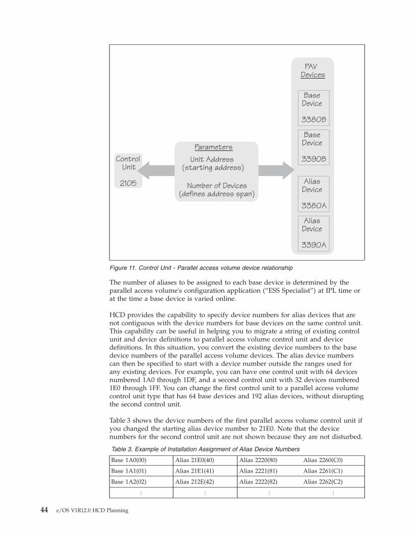
The number of aliases to be assigned to each base device is determined by theparallel access volume's configuration application (“ESS Specialist”) at IPL time orat the time a base device is varied online.
HCD provides the capability to specify device numbers for alias devices that arenot contiguous with the device numbers for base devices on the same control unit.This capability can be useful in helping you to migrate a string of existing controlunit and device definitions to parallel access volume control unit and devicedefinitions. In this situation, you convert the existing device numbers to the basedevice numbers of the parallel access volume devices. The alias device numberscan then be specified to start with a device number outside the ranges used forany existing devices. For example, you can have one control unit with 64 devicesnumbered 1A0 through 1DF, and a second control unit with 32 devices numbered1E0 through 1FF. You can change the first control unit to a parallel access volumecontrol unit type that has 64 base devices and 192 alias devices, without disruptingthe second control unit.
Table 3 shows the device numbers of the first parallel access volume control unit ifyou changed the starting alias device number to 21E0. Note that the devicenumbers for the second control unit are not shown because they are not disturbed.
Table 3. Example of Installation Assignment of Alias Device Numbers
Base 1A0(00) Alias 21E0(40) Alias 2220(80) Alias 2260(C0)
Base 1A1(01) Alias 21E1(41) Alias 2221(81) Alias 2261(C1)
Base 1A2(02) Alias 212E(42) Alias 2222(82) Alias 2262(C2)
: : : :
ControlUnit
2105
BaseDevice
3380B
BaseDevice
3390B
AliasDevice
3390A
AliasDevice
3380A
PAVDevices
Unit Address(starting address)
Number of Devices(defines address span)
Parameters
Figure 11. Control Unit - Parallel access volume device relationship
44 z/OS V1R12.0 HCD Planning
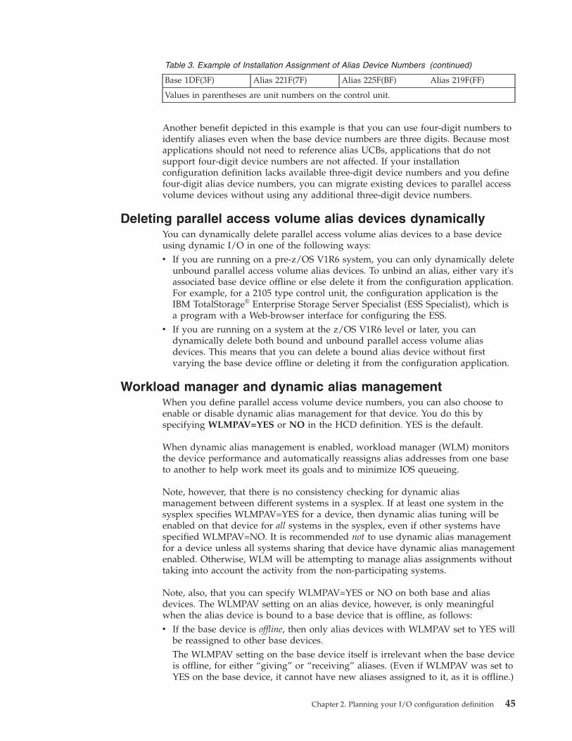
Table 3. Example of Installation Assignment of Alias Device Numbers (continued)
Base 1DF(3F) Alias 221F(7F) Alias 225F(BF) Alias 219F(FF)
Values in parentheses are unit numbers on the control unit.
Another benefit depicted in this example is that you can use four-digit numbers toidentify aliases even when the base device numbers are three digits. Because mostapplications should not need to reference alias UCBs, applications that do notsupport four-digit device numbers are not affected. If your installationconfiguration definition lacks available three-digit device numbers and you definefour-digit alias device numbers, you can migrate existing devices to parallel accessvolume devices without using any additional three-digit device numbers.
Deleting parallel access volume alias devices dynamicallyYou can dynamically delete parallel access volume alias devices to a base deviceusing dynamic I/O in one of the following ways:v If you are running on a pre-z/OS V1R6 system, you can only dynamically delete
unbound parallel access volume alias devices. To unbind an alias, either vary it'sassociated base device offline or else delete it from the configuration application.For example, for a 2105 type control unit, the configuration application is theIBM TotalStorage® Enterprise Storage Server Specialist (ESS Specialist), which isa program with a Web-browser interface for configuring the ESS.
v If you are running on a system at the z/OS V1R6 level or later, you candynamically delete both bound and unbound parallel access volume aliasdevices. This means that you can delete a bound alias device without firstvarying the base device offline or deleting it from the configuration application.
Workload manager and dynamic alias managementWhen you define parallel access volume device numbers, you can also choose toenable or disable dynamic alias management for that device. You do this byspecifying WLMPAV=YES or NO in the HCD definition. YES is the default.
When dynamic alias management is enabled, workload manager (WLM) monitorsthe device performance and automatically reassigns alias addresses from one baseto another to help work meet its goals and to minimize IOS queueing.
Note, however, that there is no consistency checking for dynamic aliasmanagement between different systems in a sysplex. If at least one system in thesysplex specifies WLMPAV=YES for a device, then dynamic alias tuning will beenabled on that device for all systems in the sysplex, even if other systems havespecified WLMPAV=NO. It is recommended not to use dynamic alias managementfor a device unless all systems sharing that device have dynamic alias managementenabled. Otherwise, WLM will be attempting to manage alias assignments withouttaking into account the activity from the non-participating systems.
Note, also, that you can specify WLMPAV=YES or NO on both base and aliasdevices. The WLMPAV setting on an alias device, however, is only meaningfulwhen the alias device is bound to a base device that is offline, as follows:v If the base device is offline, then only alias devices with WLMPAV set to YES will
be reassigned to other base devices.The WLMPAV setting on the base device itself is irrelevant when the base deviceis offline, for either “giving” or “receiving” aliases. (Even if WLMPAV was set toYES on the base device, it cannot have new aliases assigned to it, as it is offline.)
Chapter 2. Planning your I/O configuration definition 45
v If the base device is online, then the WLMPAV settings on the aliases are ignored,as follows:– If WLMPAV is set to YES on the base device, then the aliases can be
reassigned regardless of their WLMPAV settings.– If WLMPAV is set to NO on the base device, then no aliases can be
reassigned, regardless of their WLMPAV settings.
In order for dynamic alias management to be most effective, you should try tospread out your aliases in the initial definition. If one base device has several aliasdevices while other base devices have none, it will take more time for WLM toreassign the aliases appropriately. Ideally, you should have at least two aliasesassigned to each base at the outset.
Dynamic alias management can be globally enabled or disabled for the entiresysplex via the “Service Coefficients/Service Definition Options” panel of theWLM ISPF application. See the “Defining Service Coefficients and Options” topicin z/OS MVS Planning: Workload Management for more information.
Specifying I/O device parameters and featuresThis topic provides information about defining a device to the operating system.You specify parameters and features of a device to the operating system in HCD,such as:v Whether a device is considered online at IPLv Whether a direct access storage device (DASD) is shared by other systemsv Whether a device definition can be deleted dynamicallyv Whether the UCB for a device is to reside above 16 megabytesv Whether a device is automatically switchable
HCD displays only the parameters and features that are applicable to the devicetype.
Defining whether an I/O device will be dynamicEach I/O device type is represented by a unit information module (UIM), which isincluded in the product that contains the device support code. The UIM for adevice specifies whether or not the device type supports dynamic configuration. Ifyour installation includes device types that support dynamic I/O configuration,you can change your I/O configuration without performing a power-on reset orre-IPLing the system.
Using HCD, you can specify whether a device with device support code thatsupports dynamic is considered dynamic or not in the operating system definition.Defining a device as dynamic allows you to dynamically add, modify, and deletethe device definition while z/OS is running.
A device's support code and definition determine its inclusion in one of thefollowing categories:v Staticv Installation-staticv Dynamic
Table 4 on page 47 describes the categories.
46 z/OS V1R12.0 HCD Planning
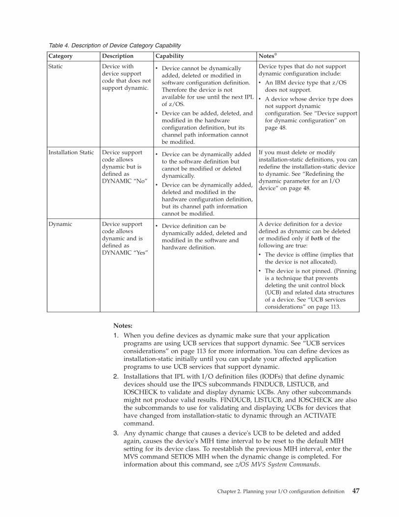
Table 4. Description of Device Category Capability
Category Description Capability Notes®
Static Device withdevice supportcode that does notsupport dynamic.
v Device cannot be dynamicallyadded, deleted or modified insoftware configuration definition.Therefore the device is notavailable for use until the next IPLof z/OS.
v Device can be added, deleted, andmodified in the hardwareconfiguration definition, but itschannel path information cannotbe modified.
Device types that do not supportdynamic configuration include:
v An IBM device type that z/OSdoes not support.
v A device whose device type doesnot support dynamicconfiguration. See “Device supportfor dynamic configuration” onpage 48.
Installation Static Device supportcode allowsdynamic but isdefined asDYNAMIC “No”
v Device can be dynamically addedto the software definition butcannot be modified or deleteddynamically.
v Device can be dynamically added,deleted and modified in thehardware configuration definition,but its channel path informationcannot be modified.
If you must delete or modifyinstallation-static definitions, you canredefine the installation-static deviceto dynamic. See “Redefining thedynamic parameter for an I/Odevice” on page 48.
Dynamic Device supportcode allowsdynamic and isdefined asDYNAMIC “Yes”
v Device definition can bedynamically added, deleted andmodified in the software andhardware definition.
A device definition for a devicedefined as dynamic can be deletedor modified only if both of thefollowing are true:
v The device is offline (implies thatthe device is not allocated).
v The device is not pinned. (Pinningis a technique that preventsdeleting the unit control block(UCB) and related data structuresof a device. See “UCB servicesconsiderations” on page 113.
Notes:
1. When you define devices as dynamic make sure that your applicationprograms are using UCB services that support dynamic. See “UCB servicesconsiderations” on page 113 for more information. You can define devices asinstallation-static initially until you can update your affected applicationprograms to use UCB services that support dynamic.
2. Installations that IPL with I/O definition files (IODFs) that define dynamicdevices should use the IPCS subcommands FINDUCB, LISTUCB, andIOSCHECK to validate and display dynamic UCBs. Any other subcommandsmight not produce valid results. FINDUCB, LISTUCB, and IOSCHECK are alsothe subcommands to use for validating and displaying UCBs for devices thathave changed from installation-static to dynamic through an ACTIVATEcommand.
3. Any dynamic change that causes a device's UCB to be deleted and addedagain, causes the device's MIH time interval to be reset to the default MIHsetting for its device class. To reestablish the previous MIH interval, enter theMVS command SETIOS MIH when the dynamic change is completed. Forinformation about this command, see z/OS MVS System Commands.
Chapter 2. Planning your I/O configuration definition 47
Device support for dynamic configurationTo determine which devices on your system support dynamic I/O configuration,check the HCD device definition panel. If the panel indicates that the specificdevice can be defined as dynamic, the device supports dynamic configuration. Forthe most current information about device support for dynamic I/O configuration,you can also see the specific device publications.
You might need the following information about display devices and CTCconnectors:v Display devices. Display devices can be dynamically added or deleted, but
cannot be used as multiple console support (MCS) consoles unless they aredefined in the CONSOLxx member and have a UCB at the IPL.
v Channel-to-channel (CTC) connectors. CTCs can be dynamically added ordeleted, but cannot be removed from global resource serialization rings, unlessthe CTC is managed by XCF. If so, your installation must stop XCF from usingthem before dynamically deleting the CTCs.
Redefining the dynamic parameter for an I/O deviceAn installation-static device that is part of an I/O configuration can be redefinedfrom installation-static to dynamic. After you redefine the device frominstallation-static to dynamic, you can dynamically modify or delete the devicefrom the configuration.
When you change a device from installation-static to dynamic, its unit controlblock (UCB) address changes. Programs on your system that save UCB addresseswill encounter problems if they attempt to use the UCB that was valid when thedevice was installation-static. To minimize such problems, stop the program beforemaking the dynamic configuration change. When you restart the program after thechange, the program scans for and finds the new UCB representing the device.
Redefining a device from installation-static to dynamic does not delete the storagefor the original UCB. You must assess the risk of how this may affect yourapplications and vendor products accessing the UCB.
Modifying or deleting an installation-static device requires two separate dynamicconfiguration changes:1. Change the installation-static device to dynamic device (by activating a new
IODF that defines the device as dynamic.) No other device characteristics forthat device can be changed on the redefinition activation.
2. Delete or modify the dynamic device (by activating another IODF that containsthe appropriate changes to the device).
Using the same steps, you can also redefine a device definition from dynamic toinstallation-static. You can do this if you mistakenly defined a device that wassupposed to be installation-static as dynamic.
The UCB for an installation-static device is accessible through the limited UCBservices. For more information, see z/OS MVS Programming: Authorized AssemblerServices Guide.
Defining a tape device as automatically switchableA tape device is dedicated when it is capable of being online to only one system at atime. The VARY ONLINE command varies the device online to the issuing systemand thereafter no other system can vary the device online until the first system
48 z/OS V1R12.0 HCD Planning
varies it offline. In contrast to a dedicated device, an automatically switchable devicecan be online to one or more of the systems that participate in tape sharing withinthe same sysplex.
Besides HCD, a tape device can be defined as automatically switchable through:v The VARY AUTOSWITCH commandv The IEEVARYD macrov The ESCON manager.
Only through HCD, however, does the definition persist beyond the duration ofthe IPL.
For devices that support automatic tape switching, the AUTOSWITCH parameterappears on the HCD Define Device Parameters / Features panel. Specify a value ofeither YES or NO on the AUTOSWITCH device parameter.
You might want to change the AUTOSWITCH attribute of a device, for example, ifyour installation needs additional devices during peak workload hours. To changea device definition from dedicated to automatically-switchable, change theAUTOSWITCH parameter value from NO to YES.
When changed, the AUTOSWITCH parameter takes effect on the next IPL (thesystem does not check it during a dynamic software activation). To dynamicallychange the AUTOSWITCH parameter (that is, without an IPL), use the VARYAUTOSWITCH command.
For help in planning your use of tape devices, see “Using automatic tapeswitching” on page 28.
Defining the location of an I/O device's unit control block(UCB)
To conserve below 16 megabyte common storage, you can define a device's UCBabove 16 megabytes. When a UCB is defined above 16 megabytes, programsrequiring a 24-bit UCB address can still access the UCB. The system automaticallycaptures the UCB at allocation. A captured UCB provides a 24-bit view into theabove 16 megabyte UCB. A captured UCB resides in below 16 megabyte privatestorage for the duration of a device allocation. The captured UCB is releasedautomatically at deallocation.
For information about accessing above 16 megabyte UCBs, see z/OS MVSProgramming: Authorized Assembler Services Guide.
Deciding whether to define above 16 megabyte UCBsBecause captured UCBs use private storage, you must carefully consider whetheryour installation should define above 16 megabyte UCBs. If you define above 16megabyte UCBs, be aware that private storage is required for captured UCBs thatare created in an address space when data sets are allocated. The system releasesthe storage when the data set is deallocated.
When you define above 16 megabyte UCBs, captured UCBs are required for certainapplications, specifically those applications using data extension block (DEB)-basedaccess methods. You can define above 16 megabyte UCBs for the applications thataccess them directly and for the applications that do not have private storageconstraints when captured UCBs are created.
Chapter 2. Planning your I/O configuration definition 49
Capturing a UCB is page-oriented. Even if an address space captures only oneUCB into private storage, the whole page of private storage is captured; asubsequent capture of a UCB that resides on the same page will not result inanother page being captured to the address space. Other address spaces that needto capture the same UCB will have their own captured UCBs.
An exception to this would be if an address space requests a UCB to be capturedto common (for example, through the macro CAPTCOM=YES) and then anotheraddress space requests a UCB on the same page to be captured to private. In thiscase, IOS returns to the second address space the common page address instead ofthe private page address. This makes sense because it is not necessary to keepmultiple copies of the UCBs below 16 megabytes when they are already capturedto common.
To determine the extent that you can take advantage of defining above 16megabyte UCBs, understand whether the following situations apply to yourinstallation. More than one case might apply depending on your installation'sapplications.
Case 1: The applications can access above 16 megabyte UCBs directly (forexample, if you are using VSAM and dynamic allocation with the NOCAPTUREoption) and the applications do not require 24-bit addresses for UCBs.
See z/OS Planning for Installation for information about subsystems that supportabove 16 megabyte UCBs.
Actions:v Define devices with above 16 megabyte UCBs.v Use dynamic allocation indicating UCBs are not to be captured.
Predicted Results:v Constraint on common storage below 16 megabytes is relieved and private
storage is not affected.
Case 2: The applications require 24-bit addresses for UCBs (for example, you areusing DEB-based access methods) and your common storage is constrained. Youcan define enough above 16 megabyte UCBs to cause the private storage area toexpand into the next megabyte (alleviating private storage constraint).
You can estimate whether you can define enough above 16 megabyte UCBs tocause the private storage area to expand into the next megabyte. At systeminitialization, the system rounds the amount of common storage to the nextmegabyte to create a megabyte boundary between below 16 megabyte commonand private storage areas. You request common storage with the SQA and CSAparameters. To determine whether the private storage area will expand to the nextmegabyte, determine the amount of storage used for rounding and subtract it fromone megabyte as shown in the following calculation:1 MB - (actual CSA - requested CSA)
actual CSA - requested CSAThe amount of rounded storage that was allocated to create a megabyteboundary. Determine this amount by subtracting the amount of CSArequested with the CSA parameter in parmlib from the actual amount ofCSA present in the system after IPL. You can determine the amount ofactual CSA by viewing the RMF™ Monitor III common storage remainingtable.
50 z/OS V1R12.0 HCD Planning
The result of this calculation is the amount of requested CSA as opposed torounded CSA. If the amount of UCB storage you are moving above 16 megabytesis greater than this value, you have captured enough UCBs to cause the privatestorage area to expand to the next megabyte. If the amount is less than this value,see cases 3 and 4.
When determining the amount of UCB storage you are moving above 16megabytes, remember that the size of a UCB is dependent on the device type. Forexample, a DASD UCB defined below 16 megabytes has approximately 128 bytesbelow 16 megabytes. The size of the prefix extension is not included because italready exists above 16 megabytes.
Action:v Define devices with above 16 megabyte UCBs.
Predicted results:v Constraint on common storage below 16 megabytes is relieved and private
storage expanded to the next megabyte so it is not constrained. There is roomfor the captured UCBs that the applications need.
Case 3: Some of your applications require 24-bit addresses for UCBs and yourcommon storage is constrained. You cannot define enough above 16 megabyteUCBs to cause the private storage area to expand into the next megabyte andprivate storage is not currently constrained. Other applications in your installationmight have enough room for the captured UCBs that they require or might notrequire captured UCBs.
Action:
v Be cautious about defining any above 16 megabyte UCBs. Capturing UCBsmight cause your private storage to become constrained. There must be enoughroom in your private storage for captured UCBs for the application.
Predicted results:
v Some constraint on common storage below 16 megabytes is relieved.v If you limited the number of above 16 megabyte UCBs, your private storage is
not constrained. You might choose to move the UCBs for certain applicationsbecause there is room for the captured UCBs that they require. When trying tomake this decision, remember that the same UCBs might be accessed by morethan one application.
Case 4: Some of your applications require 24-bit addresses for UCBs and yourcommon storage is constrained. You cannot define enough above 16 megabyteUCBs to cause the private storage area to expand into the next megabyte andprivate storage is constrained.
Action:
1. Try to relieve private storage constraint by moving as much data as possible toabove 16 megabyte private storage.For example, the BSAM, QSAM, BPAM, and BDAM access methods allow dataareas to be located above 16 megabytes. This support includes allowing thecaller to issue most SAM, PAM, and BDAM macros in 31-bit addressing moderegardless of whether the data is above or below 16 megabytes. See z/OSDFSMS Macro Instructions for Data Sets for more information.
Chapter 2. Planning your I/O configuration definition 51
Also, if you are using VSAM to allocate devices, you can use the NOCAPTUREoption when you dynamically allocate devices so UCBs are not captured.
2. Try to have private storage expand to the next megabyte by changing the CSAand SQA initialization parameters.The system rounds the amount of common storage to the next megabyte tocreate a megabyte boundary between the below 16 megabyte common andprivate storage areas. You request common storage with the SQA and CSAparameters in the IEASYSxx parmlib member.Determine the amount to reduce the CSA/SQA parameter values to forceprivate storage to the next megabyte using the following calculation:(1MB - (actual CSA - requested CSA)) - storage savings
actual CSA - requested CSAThe amount of rounded storage that was allocated to create a megabyteboundary. Determine this amount by subtracting the amount of CSArequested with the CSA parameter in parmlib from the actual amountof CSA present in the system after IPL. You can determine the amountof actual CSA by viewing the RMF Monitor III common storageremaining table.
storage savingsThe amount of common storage saved by moving UCBs above 16megabytes. If you have already moved the UCBs, you can look at theactual storage numbers before and after moving UCBs to determine thesavings or you might choose to estimate the amount you will save andthen make any changes as necessary. The size of a UCB is dependenton the device type. For example, a DASD UCB defined below 16megabytes has approximately 128 bytes below 16 megabytes. The sizeof the prefix extension is not included because it already exists above16 megabytes.
Remember that you need to reserve SQA/CSA storage for the current workloadas well as for future expansion. Make sure that you include that estimate whenyou request common storage below 16 megabytes with the CSA and SQAparameters. For more information about the parameters, see z/OS MVSInitialization and Tuning Reference.
3. Continue to define below 16 megabyte UCBs. Do not define any above 16megabyte UCBs.
Predicted results:
One of the following:1. You were able to reduce private storage constraints enough to capture the
UCBs as necessary for the application.2. You were able to tune the CSA and SQA parameters to expand to the next
megabyte.3. You decided not to define above 16 megabyte UCBs for this application.
Case 5: You are adding new devices to your installation, for example, a string of3390 devices, and you are concerned about below 16 megabyte common andprivate storage constraints.
Action:
v Define as many UCBs above 16 megabytes as possible to prevent below 16megabyte common or private storage from becoming constrained.
52 z/OS V1R12.0 HCD Planning
Define enough above 16 megabyte UCBs to prevent below 16 megabyte commonstorage from expanding into the next megabyte segment when the IODF withthe additional device definitions is used at the next IPL. For example, if only asmall amount of below 16 megabyte common storage is used to round CSA tothe next megabyte boundary, additional UCBs might cause common storage toexpand into the next megabyte. This situation could be a problem if your privatestorage is constrained because of the expansion of common storage into whatotherwise would be private storage. Prevent this problem by defining above 16megabyte UCBs; however, be aware that some private storage might be used forcaptured UCBs depending on your applications.
Predicted results:
v Constraint on common below 16 megabyte storage is not adversely affected bythe addition of the new devices.
Defining an above 16 megabyte UCBYou can use HCD to define a device's UCB above 16 megabytes if the device's unitinformation module (UIM) indicates that the device support code enables above 16megabyte UCBs. If the device support code supports above 16 megabyte UCBs, theLOCANY parameter appears on the HCD Define Device Parameters / Featurespanel. Specify a value for the LOCANY device parameter to either:v Define a device's UCB below 16 megabytes only (LOCANY is No). The UCB
cannot reside in 31-bit storage.v Define a device's UCB above 16 megabytes (LOCANY is Yes). The UCB can
reside in 31-bit storage.
The default for LOCANY ( if it is not specified by the UIM) is No. This can beoverwritten by including the option OS-PARM-DEFAULT = LOCANY,YES in theHCD profile.
You can dynamically change the definition of a UCB. To dynamically change adefinition from below 16 megabytes to above 16 megabytes, change the LOCANYparameter value from "No" to "Yes" and activate the new IODF.
Defining allocation preferencesThis topic gives background information about I/O device allocation, which youneed to understand before defining the EDT and esoteric device groups in yourconfiguration.
You can control the allocation preferences for I/O devices using HCD. First, youmust understand how devices are allocated for jobs in z/OS.
Understanding I/O device allocation in z/OSWhen you submit a job, you identify I/O devices required by the job. The deviceinformation can be obtained from either a catalog, SMS overrides, or specific UNITparameters on DD statements. Before the job can continue execution, z/OS mustallocate all those devices to the job.
There are three ways to specify device allocation for a job using UNIT parameterson DD statements. On the UNIT= parameter, specify one of the following:v A specific device numberv A generic device typev An esoteric device group
Chapter 2. Planning your I/O configuration definition 53
Indicating a specific device for allocationTo request a device explicitly for a job, specify a device number on the UNIT=parameter or on the corresponding dynamic allocation parameter. If that device isavailable, z/OS allocates the device to the job. However, if the device isunavailable (for example, allocated to another job), your job must wait until thedevice is available for allocation.
Specifying a generic device type for allocationz/OS logically groups device types with similar characteristics and assigns thegroup a generic name. Such a group is called a generic device type. z/OS, forexample, groups the 3330-1, 3330-2, and 3333-1 into a generic device type named3330. Any time a program allocates a 3330, z/OS interprets it to mean any of thedevices in that generic device type.
To request a device allocation, you can specify a generic device type on the UNIT=parameter. z/OS allocates a device from the specified generic device type. Forexample, if you code the following DD statement://OUTPUT DD UNIT=3330,...
z/OS allocates a device from generic device type 3330.
If you specify a device number, such as 3330, that may be mistaken for a unitdevice type, precede the device number with a slash.
For example, if you code the following DD statement://OUTPUT DD UNIT=/3330,...
z/OS allocates the device that has the device number 3330.
Note: An esoteric device name must not contain a slash (/).
For more information, see the UNIT= parameter description in z/OS MVS JCLReference.
Specifying an esoteric device group for allocation
A job that specifies an esoteric device group is requesting z/OS to allocate a devicefrom that group. An esoteric device group can include devices of different genericdevice types. All of the devices that you assign to an esoteric device group must beof the same device class with the following exception: you can define esotericdevice groups that contain devices from both DASD and tape device classes butthis is not recommended.
Devices belong to one of the following classes:v Channel-to-channel adaptersv Communication devicesv Direct access devicesv Display devicesv Character readersv Tape devicesv Unit record devices
To request device allocation, you can specify an esoteric device group on theUNIT= parameter. For instance, DASD and TAPE are group names that identify agroup of devices eligible for allocation to satisfy a UNIT=group request (forexample, UNIT=DASD, or UNIT=TAPE on the DD JCL statement).
54 z/OS V1R12.0 HCD Planning
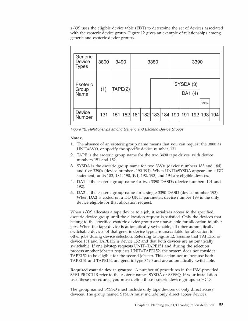
z/OS uses the eligible device table (EDT) to determine the set of devices associatedwith the esoteric device group. Figure 12 gives an example of relationships amonggeneric and esoteric device groups.
Notes:
1. The absence of an esoteric group name means that you can request the 3800 asUNIT=3800, or specify the specific device number, 131.
2. TAPE is the esoteric group name for the two 3490 tape drives, with devicenumbers 151 and 152.
3. SYSDA is the esoteric group name for two 3380s (device numbers 183 and 184)and five 3390s (device numbers 190-194). When UNIT=SYSDA appears on a DDstatement, units 183, 184, 190, 191, 192, 193, and 194 are eligible devices.
4. DA1 is the esoteric group name for two 3390 DASDs (device numbers 191 and192).
5. DA2 is the esoteric group name for a single 3390 DASD (device number 193).When DA2 is coded on a DD UNIT parameter, device number 193 is the onlydevice eligible for that allocation request.
When z/OS allocates a tape device to a job, it serializes access to the specifiedesoteric device group until the allocation request is satisfied. Only the devices thatbelong to the specified esoteric device group are unavailable for allocation to otherjobs. When the tape device is automatically switchable, all other automaticallyswitchable devices of that generic device type are unavailable for allocation toother jobs during device selection. Referring to Figure 12, assume that TAPE151 isdevice 151 and TAPE152 is device 152 and that both devices are automaticallyswitchable. If one jobstep requests UNIT=TAPE151 and during the selectionprocess another jobstep requests UNIT=TAPE152, the system does not considerTAPE152 to be eligible for the second jobstep. This action occurs because bothTAPE151 and TAPE152 are generic type 3490 and are automatically switchable.
Required esoteric device groups: A number of procedures in the IBM-providedSYS1.PROCLIB refer to the esoteric names SYSDA or SYSSQ. If your installationuses these procedures, you must define these esoteric device groups to HCD.
The group named SYSSQ must include only tape devices or only direct accessdevices. The group named SYSDA must include only direct access devices.
194193
DA2(5)
192
DA1 (4)
SYSDA (3)
3390
191190184183
3380
182181152151
3490
TAPE(2)
131
3800
(1)
DeviceNumber
GenericDeviceTypes
EsotericGroupName
Figure 12. Relationships among Generic and Esoteric Device Groups
Chapter 2. Planning your I/O configuration definition 55
In addition, your installation might use other cataloged procedures that also referto these or to other esoteric names. To determine which esoteric groups yourinstallation uses, check the UNIT= parameter on the cataloged procedure DDstatements.
Specifying order in an esoteric with the device preference tableAn esoteric device group can include devices of more than one generic devicetype. When z/OS attempts to allocate a demountable device, a unit record, or aprinter from an esoteric device group, it turns to the device preference table thatdefines the order in which to attempt the allocation. The system uses the table toserialize its selection of those devices.
HCD provides a predefined device preference table that defines the generic devicetypes and lists them in order of performance. (The first device type on the list isthe fastest. The last device type on the list is the slowest.) You can use the defaultdevice preference table values for a generic or you can specify a different value tochange the allocation order.
For tape requests, the system considers many factors: the type of request, thedevices eligible to satisfy the request, and the characteristics of each eligible device.Based on these factors, the system selects the optimal device to allocate. z/OSallows users to participate in the selection process through the use of SSI functioncode 78. For details on how to use function code 78, see z/OS MVS Using theSubsystem Interface.
Related information:
v For the most current information about device support, see the specific deviceinformation or use the “Query supported hardware and installed UIMs” optionon the HCD primary task selection panel.
v For information about printing reports through HCD and an example of theSupported Hardware report, see z/OS HCD User's Guide.
Advantages of specifying an esoteric device group
By requesting a specific device (for example, UNIT=570), you limit z/OS to achoice of only one device, thereby decreasing the probability that the device will beavailable when the job needs it. In contrast, by requesting a generic device type,you can allow z/OS a choice of several devices, thereby increasing the probabilitythat a device will be available when the job needs it. Of course, this increase inprobability assumes that there will be more than one device of that generic typeavailable for allocation.
When you request a generic device type, z/OS serializes access to that genericdevice type. This means that z/OS does not allocate devices from that genericdevice type to other jobs until z/OS satisfies your jobstep allocation request.Because z/OS makes the entire generic device type unavailable for allocation toother jobs, there might be a delay in satisfying other jobs' allocation requests.Therefore, requesting a generic device type increases the probability that there willbe a delay in satisfying allocation requests for other jobs. However, waiting for ageneric device type generally takes much less time than waiting for a specificdevice.
Assuming that the esoteric device group identifies more than one device, a devicewill more likely be available for a UNIT=TAPE request, for example, than if therequest was for a specific device. Also, if you assume that the esoteric devicegroup does not contain all of the devices from any one generic device type, devices
56 z/OS V1R12.0 HCD Planning
from each generic device type might still be available for allocation to other jobswhile z/OS serializes access to the esoteric device group.
To summarize how the system handles the different UNIT specifications, here arethree examples. The first two examples describes dedicated devices and the thirddescribes automatically switchable devices.
The first example compares the likelihood of the system being able to satisfy thefollowing specific and generic device requests:v UNIT=270v UNIT=3480, where the devices are defined at addresses 270, 273, 285, 294, 366,
and 414.
In this case, it is more likely the request can be satisfied by any of the six deviceseligible with the UNIT=3480 request than with the UNIT=270 request.
The second example shows how you can subdivide devices into two esotericspecifications so that two jobs can have similar device requests satisfied at thesame time. The devices are defined as follows:v TAPE1 is 270, 273, and 285v TAPE2 is 294, 366, and 414.
In this case, jobs that request TAPE1 can be in allocation at the same time as jobsthat request TAPE2.
The third example is the same as the second example and the UNIT specificationsare the same; however, all devices are automatically switchable. In this case, jobsthat request TAPE1 and jobs that request TAPE2 cannot be in allocation at thesame time. The second job will have to wait for the first job to complete allocation.This will be true whether the jobs are on the same system or on different systems.
Holding or releasing resources while a job waitsAssuming that you are not using JES3 pre-execution setup, to make best use ofdevice allocation, you must decide whether the system should hold or releaseresources (non-sharable devices and volumes) while a job waits for those resources.When the operator requests that allocation for a specific job is to wait forresources, the system issues a message that asks the operator to reply with eitherHOLD or NOHOLD.
HOLDThe system holds non-sharable devices and volumes already allocated tothe job. Select this option if the needed resources are constantly beingfreed, and allocation requests for other jobs will probably not be held upby the requests made for this job. This job can hold up other requests ineither of two ways:1. The job has already allocated units needed for another job.2. The job is waiting for devices to which z/OS is controlling access
through serialization.
NOHOLDThe system releases non-sharable devices and volumes already allocated tothe job. Select this option if the needed resources may not be freed forsome time, and allocation requests for this job are likely to hold upallocation requests issued for other jobs.
Requests for dynamic allocation are not held up by requests waiting for batchallocation, even though the jobs awaiting batch allocation are holding resources.
Chapter 2. Planning your I/O configuration definition 57
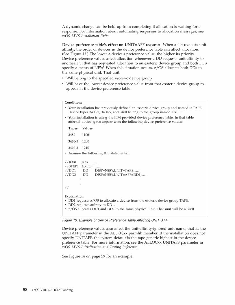
A dynamic change can be held up from completing if allocation is waiting for aresponse. For information about automating responses to allocation messages, seez/OS MVS Installation Exits.
Device preference table's effect on UNIT=AFF request: When a job requests unitaffinity, the order of devices in the device preference table can affect allocation.(See Figure 13.) The lower a device's preference value, the higher its priority.Device preference values affect allocation whenever a DD requests unit affinity toanother DD that has requested allocation to an esoteric device group and both DDsspecify a status of NEW. When this situation occurs, z/OS allocates both DDs tothe same physical unit. That unit:v Will belong to the specified esoteric device groupv Will have the lowest device preference value from that esoteric device group to
appear in the device preference table
Device preference values also affect the unit-affinity-ignored unit name, that is, theUNITAFF parameter in the ALLOCxx parmlib member. If the installation does notspecify UNITAFF, the system default is the tape generic highest in the devicepreference table. For more information, see the ALLOCxx UNITAFF parameter inz/OS MVS Initialization and Tuning Reference.
See Figure 14 on page 59 for an example.
Conditions
v Your installation has previously defined an esoteric device group and named it TAPE.Device types 3400-3, 3400-5, and 3480 belong to the group named TAPE.
v Your installation is using the IBM-provided device preference table. In that tableaffected device types appear with the following device preference values:
Types Values
3480 1100
3400-5 1200
3400-3 1210
v Assume the following JCL statements:
//JOB1 JOB .......//STEP1 EXEC .......//DD1 DD DISP=NEW,UNIT=TAPE,.......//DD2 DD DISP=NEW,UNIT=AFF=DD1,.......
.
.//
Explanationv DD1 requests z/OS to allocate a device from the esoteric device group TAPE.v DD2 requests affinity to DD1.v z/OS allocates DD1 and DD2 to the same physical unit. That unit will be a 3480.
Figure 13. Example of Device Preference Table Affecting UNIT=AFF
58 z/OS V1R12.0 HCD Planning
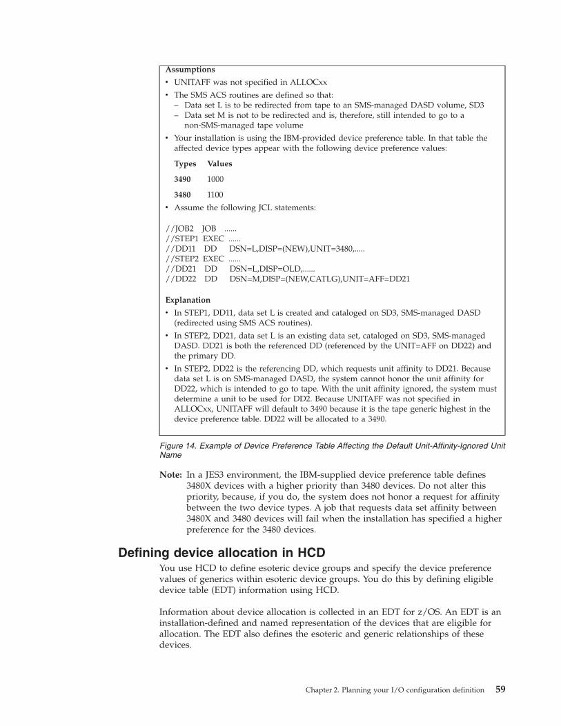
Note: In a JES3 environment, the IBM-supplied device preference table defines3480X devices with a higher priority than 3480 devices. Do not alter thispriority, because, if you do, the system does not honor a request for affinitybetween the two device types. A job that requests data set affinity between3480X and 3480 devices will fail when the installation has specified a higherpreference for the 3480 devices.
Defining device allocation in HCDYou use HCD to define esoteric device groups and specify the device preferencevalues of generics within esoteric device groups. You do this by defining eligibledevice table (EDT) information using HCD.
Information about device allocation is collected in an EDT for z/OS. An EDT is aninstallation-defined and named representation of the devices that are eligible forallocation. The EDT also defines the esoteric and generic relationships of thesedevices.
Assumptions
v UNITAFF was not specified in ALLOCxx
v The SMS ACS routines are defined so that:– Data set L is to be redirected from tape to an SMS-managed DASD volume, SD3– Data set M is not to be redirected and is, therefore, still intended to go to a
non-SMS-managed tape volume
v Your installation is using the IBM-provided device preference table. In that table theaffected device types appear with the following device preference values:
Types Values
3490 1000
3480 1100
v Assume the following JCL statements:
//JOB2 JOB ......//STEP1 EXEC ......//DD11 DD DSN=L,DISP=(NEW),UNIT=3480,.....//STEP2 EXEC ......//DD21 DD DSN=L,DISP=OLD,......//DD22 DD DSN=M,DISP=(NEW,CATLG),UNIT=AFF=DD21
Explanation
v In STEP1, DD11, data set L is created and cataloged on SD3, SMS-managed DASD(redirected using SMS ACS routines).
v In STEP2, DD21, data set L is an existing data set, cataloged on SD3, SMS-managedDASD. DD21 is both the referenced DD (referenced by the UNIT=AFF on DD22) andthe primary DD.
v In STEP2, DD22 is the referencing DD, which requests unit affinity to DD21. Becausedata set L is on SMS-managed DASD, the system cannot honor the unit affinity forDD22, which is intended to go to tape. With the unit affinity ignored, the system mustdetermine a unit to be used for DD2. Because UNITAFF was not specified inALLOCxx, UNITAFF will default to 3490 because it is the tape generic highest in thedevice preference table. DD22 will be allocated to a 3490.
Figure 14. Example of Device Preference Table Affecting the Default Unit-Affinity-Ignored UnitName
Chapter 2. Planning your I/O configuration definition 59
During each IPL, or during a dynamic configuration change, your installationidentifies the EDT that z/OS is to use. During an IPL, you identify the EDT in theLOADxx member. See Chapter 3, “Specifying an I/O configuration at IPL,” onpage 73 for a description of the LOADxx member. During a dynamic configurationchange, you identify the EDT on the HCD Activate New Configuration panel or onthe ACTIVATE command. Jobs that run after the IPL or dynamic change canrequest device allocations from any of the esoteric device groups assigned to theselected EDT.
Your installation can define multiple EDTs in each I/O definition file (IODF). Foreach I/O configuration, you can define:v One EDT with no changes to the device preference tablev One EDT with changes to the device preference tablev Multiple EDTs with or without changes to the device preference tables
You define each EDT with a unique identifier in HCD.
Note: In a JES3 environment, JES3 supports only one EDT per I/O configuration.If a JES3 installation defines more than one EDT in a configuration, JES3 willsupport only the first EDT defined.
Each EDT definition can include:v Definitions for one or more esoteric device groups (See “Defining esoteric device
groups in an EDT using HCD.”)v Changes to the device preference table (See “Changing the device preference
table order.”)v Names of the generic device types you want to make eligible for VIO (See
“Defining devices as virtual I/O (VIO) eligible” on page 61.)
You can use HCD to view the configuration data in an EDT. Programs can viewinformation from the currently active EDT using the EDTINFO macro. (See z/OSMVS Programming: Assembler Services Reference ABE-HSP.)
Defining esoteric device groups in an EDT using HCDUse HCD to define an esoteric group, assign the group a name, and identify theI/O devices that you want included in the group. The name you assign to anesoteric device group is called the esoteric name. To request allocation of a devicefrom an esoteric device group, specify the esoteric name on the UNIT= parameterof a JCL DD statement.
In JCL terminology, an esoteric name is called a group name.
Within a given EDT, no two esoteric device groups can have the same name. Anesoteric device group in one EDT, however, can have the same name as an esotericdevice group in another EDT.
Do not use esoteric names SYSALLDA, SYS3480R, or SYS348XR, which arereserved for use by IBM.
Changing the device preference table orderThe device preference table defines the order of devices that z/OS uses to satisfyan allocation request. To change the device order that z/OS is to use whenattempting to satisfy an allocation request, use HCD to define a new preferencetable order as part of a new EDT definition in the IODF. In the device preference
60 z/OS V1R12.0 HCD Planning
table, devices with lower preference values have higher priority. If the allocation isunsuccessful, z/OS continues the attempt following the order specified in theIBM-provided device preference table.
When you define a device, HCD automatically defines the generic device type inthe EDT. You can use HCD to view the generics defined in an EDT. For eachgeneric in an EDT, you can specify an installation device preference table value tospecify the order the generic is allocated within an esoteric or you can keep theIBM default device preference value.
Defining devices as virtual I/O (VIO) eligibleVIO refers to data set allocations that exist in paging storage only. z/OS does notuse a real device unless z/OS must page out the data set. If z/OS must page outthe data set, z/OS writes it to a paging device. Programs that use VIO data setsaccess them just as if the data sets were allocated to a real I/O device.
You can allocate only temporary data sets to VIO. To request a VIO allocation, theUNIT= parameter on your DD statement must specify an esoteric device group orgeneric device type that is eligible for VIO. z/OS MVS JCL Reference and z/OS MVSJCL User's Guide explain, in detail, how to make the request. Those books alsoexplain the conditions that must be met before z/OS satisfies a VIO allocationrequest.
You use HCD to identify the esoteric device groups or the generic device typesthat you want to be eligible for VIO allocation. z/OS will allocate only DASD forVIO. Therefore, any group that you identify must contain at least one DASD.
You can identify one or more direct access generic device types that you want tomake eligible for VIO.
EDTs for dynamic configurationSome dynamic configuration changes that you can make to an EDT are:v Changes to esoteric groupsv Changes to the device preference table values for generics, which determines the
order in which devices are allocated from an esoteric group
These dynamic configuration changes could be used to define an IODF with thesame hardware configuration but with a different ID for the EDT. The different IDfor the EDT allows an installation to activate a configuration with a differentdevice preference order and different esoteric device groups for different jobs, suchas off-shift work. Other dynamic configuration changes that affect the EDT are:v Adding devices, including appropriate new generic namesv Deleting devicesv Modifying devices, which results in deleting then adding the same device
numbers (Message IOS502I reports the deleted and added device.)
A dynamic configuration change causes z/OS to activate a new EDT definition.
Primary and secondary EDTs: Usually, z/OS uses one eligible device table (EDT)to process allocation requests. However, when you dynamically change yoursystem's software I/O configuration definition, z/OS must use two EDTs toprocess the change:v The primary EDT processes all current and new allocation requests. z/OS runs
with only the primary EDT until you make a dynamic configuration change.z/OS then activates a new primary EDT for the new I/O configuration, whichmakes the old primary EDT the secondary EDT.
Chapter 2. Planning your I/O configuration definition 61
v The secondary EDT receives no new allocation requests. The system deletes thesecondary EDT when it finishes the allocation requests issued before thedynamic configuration change.
A second activation may fail if the previous activation is not finished because workis still accessing the secondary EDT.
Migrating to subchannel setsIn a System z environment with z/OS V1R7 or later installed, you can defineanother subchannel set with ID 1 (SS1) in addition to the existing subchannel set(SS0) in a logical channel subsystem. This ability relieves the constraint for thenumber of devices that can be accessed by an LPAR. You can define parallel accessvolume (PAV) alias devices (device types 3380A, 3390A) of the 2105, 2107 and 1750DASD control units to SS1. In SS0, you can place 63.75K devices, and in SS1 youcan place 64K parallel access volume alias devices. Device numbers can beduplicated across subchannel sets. See Figure 5 on page 19.
Scenario: All LPARs are z/OS V1R7 or laterUsing subchannel set support when all z/OS LPARs are IPLed on a release thatsupports subchannel sets is the easier of the two migration methods. Alias devicesthat are currently in subchannel set 0 (SS0) can be moved into subchannel set 1(SS1), through your normal dynamic configuration change method. After allchanges are made to the IODF and it is active on the System z9 BC or z9 EC, youhave successfully reassigned your alias devices from SS0 to SS1. Doing so frees thenumber of device addresses in SS0 equal to the number of alias devices movedinto SS1. Next, define more physical volumes to SS0.
Note that the logical and physical device unit addresses assigned to a device on acontrol unit must be unique; you cannot define the same CU/device unit addressto a device in both SS0 and SS1. For example, if you want to define the PAV baseand alias devices in the range 8000-807F in different subchannel sets, but on thesame control unit, you can define the devices as follows:v Base devices, range 8000-807F in SS0, unit address 00-7F (CU number 8000)v Alias devices, range 8000-807F in SS1, unit address 80-FF (CU number 8000).
Scenario: Some LPARs are pre-z/OS V1R7When some releases support subchannel sets and some do not, the LPARs thatsupport subchannel sets must be isolated into a separate logical channelsubsystem. This is necessary because a device can only be defined to onesubchannel set within a logical channel subsystem. When a device is defined tosubchannel set 1 (SS1) within a logical channel subsystem, pre-z/OS V1R7 systemsthat are IPLed into the same logical channel subsystem will not have access to thatdevice.
How to accomplish this depends on whether or not you have an available logicalchannel subsystem to use for the z/OS V1R7 system. When a logical channelsubsystem is available, it has partitions that are not being used.v One or more logical channel subsystems are availablev All the logical channel subsystems are in use
If there is an available logical channel subsystem, it will be an ideal staging groundto introduce subchannel sets. When the processor is in use prior to z/OS V1R7, aneffective migration path with an available logical channel subsystem is as follows:1. Define a z/OS LPAR into an available channel subsystem
62 z/OS V1R12.0 HCD Planning
2. Span channels to the new LPAR in the IODF3. Write the IOCDS out to the processor4. Dynamically activate the new IODF if all releases are at z/OS V1R6; releases
prior to z/OS V1R6 require a POR.5. Activate the LPAR and IPL z/OS V1R76. Convert the current IODF to IODF version 57. Define the desired subchannel set size for every logical channel subsystems8. Create an IODF with a second OS configuration as a copy of the first9. Move the targeted alias devices from SS0 to SS1 in the second OS
configuration.10. Write the IOCDS out to the CP11. Update the LOADxx member to specify the new OSCONFIG12. POR with the new IOCDS.
If no channel subsystem is available, use these actions starting with Step 5.
For more information about defining multiple subchannel sets using HCD, seez/OS HCD User's Guide.
Example of migrating devices between subchannel setsThis topic shows a possible approach for organizing your PAV base and aliasdevices in two different subchannel sets:v “Numbering schemes” on page 64 introduces some methods for organizing
device numbers and unit addresses of the devices.v “Using HCD to move alias devices into a different subchannel set and closing
the gaps in the device number range” on page 67 shows how to use HCD tomove PAV alias devices from SS0 to SS1, applying one of discussed numberingschemes to fill the numbering gaps.
To use the information in this section, you must understand PAV and HyperPAVtechnology, and how to select an appropriate ratio between base and alias devices.Also be aware that the described consolidation of device ranges does not considerany involved migration of data. For this purpose, various approaches are available,such as DFSMSdss, TDMF®, or LDMF.
Further, an understanding of the following topics would be helpful in migratingdevices between subchannel sets:v Availability of free device ranges within the existing 64K channel subsystem
limitv DASD capacity planning detail for a period of 5 years or longerv Logical Subsystem alignment of existing and future disk subsystemsv Disk subsystem support of new technology (for example, HyperPAV)v Performance profile of disk subsystemsv DASD replication requirements.
Device number alignmentNo correspondence is needed between device numbers in the two subchannel sets.For example, device number 8000 in subchannel set 0 (SS0) and device number8000 in subchannel set 1 (SS1) can be completely separate devices.
Typically, you define base devices (for example, device type 3390B) from the startof the unit address range (unit address 00 forwards) and define alias devices from
Chapter 2. Planning your I/O configuration definition 63
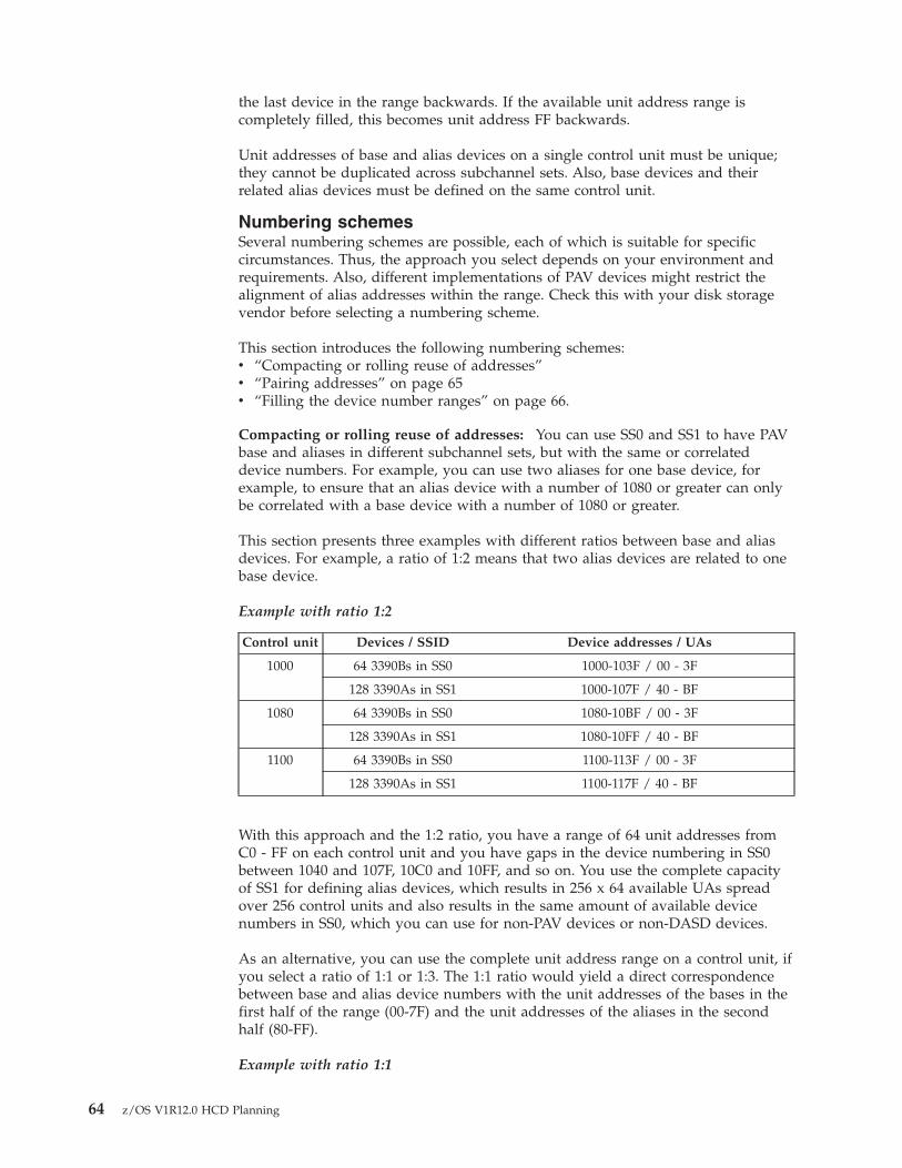
the last device in the range backwards. If the available unit address range iscompletely filled, this becomes unit address FF backwards.
Unit addresses of base and alias devices on a single control unit must be unique;they cannot be duplicated across subchannel sets. Also, base devices and theirrelated alias devices must be defined on the same control unit.
Numbering schemesSeveral numbering schemes are possible, each of which is suitable for specificcircumstances. Thus, the approach you select depends on your environment andrequirements. Also, different implementations of PAV devices might restrict thealignment of alias addresses within the range. Check this with your disk storagevendor before selecting a numbering scheme.
This section introduces the following numbering schemes:v “Compacting or rolling reuse of addresses”v “Pairing addresses” on page 65v “Filling the device number ranges” on page 66.
Compacting or rolling reuse of addresses: You can use SS0 and SS1 to have PAVbase and aliases in different subchannel sets, but with the same or correlateddevice numbers. For example, you can use two aliases for one base device, forexample, to ensure that an alias device with a number of 1080 or greater can onlybe correlated with a base device with a number of 1080 or greater.
This section presents three examples with different ratios between base and aliasdevices. For example, a ratio of 1:2 means that two alias devices are related to onebase device.
Example with ratio 1:2
Control unit Devices / SSID Device addresses / UAs
1000 64 3390Bs in SS0 1000-103F / 00 - 3F
128 3390As in SS1 1000-107F / 40 - BF
1080 64 3390Bs in SS0 1080-10BF / 00 - 3F
128 3390As in SS1 1080-10FF / 40 - BF
1100 64 3390Bs in SS0 1100-113F / 00 - 3F
128 3390As in SS1 1100-117F / 40 - BF
With this approach and the 1:2 ratio, you have a range of 64 unit addresses fromC0 - FF on each control unit and you have gaps in the device numbering in SS0between 1040 and 107F, 10C0 and 10FF, and so on. You use the complete capacityof SS1 for defining alias devices, which results in 256 x 64 available UAs spreadover 256 control units and also results in the same amount of available devicenumbers in SS0, which you can use for non-PAV devices or non-DASD devices.
As an alternative, you can use the complete unit address range on a control unit, ifyou select a ratio of 1:1 or 1:3. The 1:1 ratio would yield a direct correspondencebetween base and alias device numbers with the unit addresses of the bases in thefirst half of the range (00-7F) and the unit addresses of the aliases in the secondhalf (80-FF).
Example with ratio 1:1
64 z/OS V1R12.0 HCD Planning
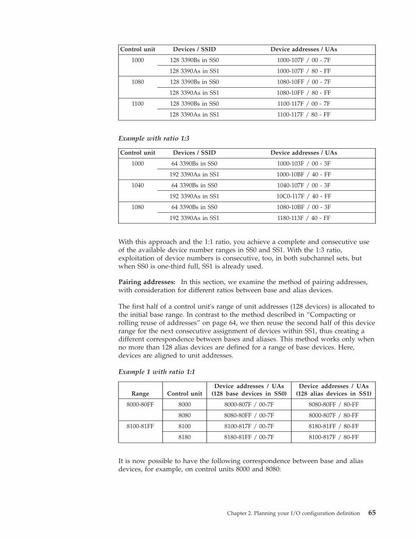
Control unit Devices / SSID Device addresses / UAs
1000 128 3390Bs in SS0 1000-107F / 00 - 7F
128 3390As in SS1 1000-107F / 80 - FF
1080 128 3390Bs in SS0 1080-10FF / 00 - 7F
128 3390As in SS1 1080-10FF / 80 - FF
1100 128 3390Bs in SS0 1100-117F / 00 - 7F
128 3390As in SS1 1100-117F / 80 - FF
Example with ratio 1:3
Control unit Devices / SSID Device addresses / UAs
1000 64 3390Bs in SS0 1000-103F / 00 - 3F
192 3390As in SS1 1000-10BF / 40 - FF
1040 64 3390Bs in SS0 1040-107F / 00 - 3F
192 3390As in SS1 10C0-117F / 40 - FF
1080 64 3390Bs in SS0 1080-10BF / 00 - 3F
192 3390As in SS1 1180-113F / 40 - FF
With this approach and the 1:1 ratio, you achieve a complete and consecutive useof the available device number ranges in SS0 and SS1. With the 1:3 ratio,exploitation of device numbers is consecutive, too, in both subchannel sets, butwhen SS0 is one-third full, SS1 is already used.
Pairing addresses: In this section, we examine the method of pairing addresses,with consideration for different ratios between base and alias devices.
The first half of a control unit's range of unit addresses (128 devices) is allocated tothe initial base range. In contrast to the method described in “Compacting orrolling reuse of addresses” on page 64, we then reuse the second half of this devicerange for the next consecutive assignment of devices within SS1, thus creating adifferent correspondence between bases and aliases. This method works only whenno more than 128 alias devices are defined for a range of base devices. Here,devices are aligned to unit addresses.
Example 1 with ratio 1:1
Range Control unitDevice addresses / UAs
(128 base devices in SS0)Device addresses / UAs
(128 alias devices in SS1)
8000-80FF 8000 8000-807F / 00-7F 8080-80FF / 80-FF
8080 8080-80FF / 00-7F 8000-807F / 80-FF
8100-81FF 8100 8100-817F / 00-7F 8180-81FF / 80-FF
8180 8180-81FF / 00-7F 8100-817F / 80-FF
It is now possible to have the following correspondence between base and aliasdevices, for example, on control units 8000 and 8080:
Chapter 2. Planning your I/O configuration definition 65
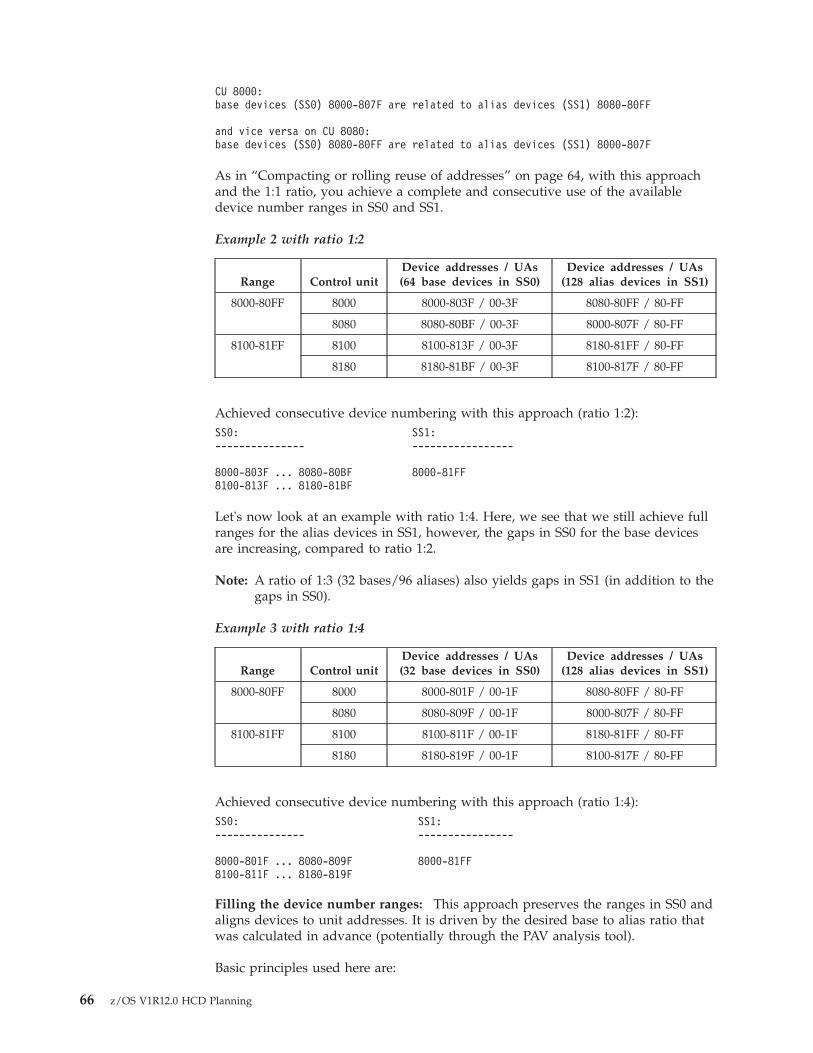
CU 8000:base devices (SS0) 8000-807F are related to alias devices (SS1) 8080-80FF
and vice versa on CU 8080:base devices (SS0) 8080-80FF are related to alias devices (SS1) 8000-807F
As in “Compacting or rolling reuse of addresses” on page 64, with this approachand the 1:1 ratio, you achieve a complete and consecutive use of the availabledevice number ranges in SS0 and SS1.
Example 2 with ratio 1:2
Range Control unitDevice addresses / UAs(64 base devices in SS0)
Device addresses / UAs(128 alias devices in SS1)
8000-80FF 8000 8000-803F / 00-3F 8080-80FF / 80-FF
8080 8080-80BF / 00-3F 8000-807F / 80-FF
8100-81FF 8100 8100-813F / 00-3F 8180-81FF / 80-FF
8180 8180-81BF / 00-3F 8100-817F / 80-FF
Achieved consecutive device numbering with this approach (ratio 1:2):SS0: SS1:--------------- -----------------
8000-803F ... 8080-80BF 8000-81FF8100-813F ... 8180-81BF
Let's now look at an example with ratio 1:4. Here, we see that we still achieve fullranges for the alias devices in SS1, however, the gaps in SS0 for the base devicesare increasing, compared to ratio 1:2.
Note: A ratio of 1:3 (32 bases/96 aliases) also yields gaps in SS1 (in addition to thegaps in SS0).
Example 3 with ratio 1:4
Range Control unitDevice addresses / UAs(32 base devices in SS0)
Device addresses / UAs(128 alias devices in SS1)
8000-80FF 8000 8000-801F / 00-1F 8080-80FF / 80-FF
8080 8080-809F / 00-1F 8000-807F / 80-FF
8100-81FF 8100 8100-811F / 00-1F 8180-81FF / 80-FF
8180 8180-819F / 00-1F 8100-817F / 80-FF
Achieved consecutive device numbering with this approach (ratio 1:4):SS0: SS1:--------------- ----------------
8000-801F ... 8080-809F 8000-81FF8100-811F ... 8180-819F
Filling the device number ranges: This approach preserves the ranges in SS0 andaligns devices to unit addresses. It is driven by the desired base to alias ratio thatwas calculated in advance (potentially through the PAV analysis tool).
Basic principles used here are:
66 z/OS V1R12.0 HCD Planning
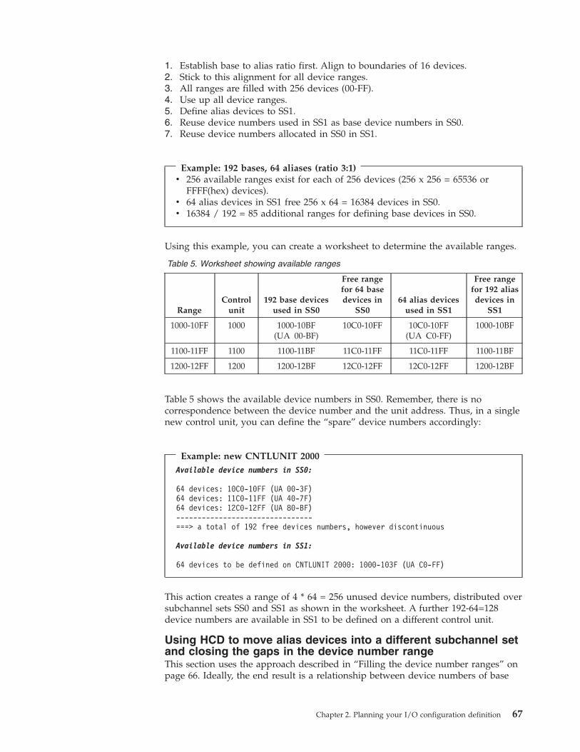
1. Establish base to alias ratio first. Align to boundaries of 16 devices.2. Stick to this alignment for all device ranges.3. All ranges are filled with 256 devices (00-FF).4. Use up all device ranges.5. Define alias devices to SS1.6. Reuse device numbers used in SS1 as base device numbers in SS0.7. Reuse device numbers allocated in SS0 in SS1.
Example: 192 bases, 64 aliases (ratio 3:1)v 256 available ranges exist for each of 256 devices (256 x 256 = 65536 or
FFFF(hex) devices).v 64 alias devices in SS1 free 256 x 64 = 16384 devices in SS0.v 16384 / 192 = 85 additional ranges for defining base devices in SS0.
Using this example, you can create a worksheet to determine the available ranges.
Table 5. Worksheet showing available ranges
RangeControl
unit192 base devices
used in SS0
Free rangefor 64 basedevices in
SS064 alias devices
used in SS1
Free rangefor 192 aliasdevices in
SS1
1000-10FF 1000 1000-10BF(UA 00-BF)
10C0-10FF 10C0-10FF(UA C0-FF)
1000-10BF
1100-11FF 1100 1100-11BF 11C0-11FF 11C0-11FF 1100-11BF
1200-12FF 1200 1200-12BF 12C0-12FF 12C0-12FF 1200-12BF
Table 5 shows the available device numbers in SS0. Remember, there is nocorrespondence between the device number and the unit address. Thus, in a singlenew control unit, you can define the “spare” device numbers accordingly:
Example: new CNTLUNIT 2000Available device numbers in SS0:
64 devices: 10C0-10FF (UA 00-3F)64 devices: 11C0-11FF (UA 40-7F)64 devices: 12C0-12FF (UA 80-BF)--------------------------------===> a total of 192 free devices numbers, however discontinuous
Available device numbers in SS1:
64 devices to be defined on CNTLUNIT 2000: 1000-103F (UA C0-FF)
This action creates a range of 4 * 64 = 256 unused device numbers, distributed oversubchannel sets SS0 and SS1 as shown in the worksheet. A further 192-64=128device numbers are available in SS1 to be defined on a different control unit.
Using HCD to move alias devices into a different subchannel setand closing the gaps in the device number rangeThis section uses the approach described in “Filling the device number ranges” onpage 66. Ideally, the end result is a relationship between device numbers of base
Chapter 2. Planning your I/O configuration definition 67
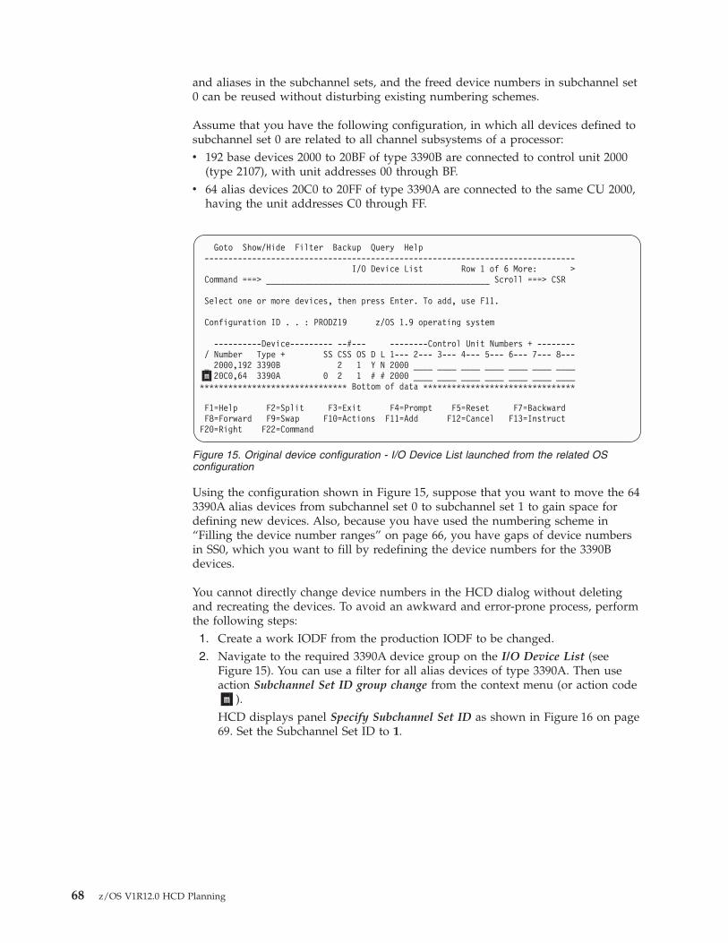
and aliases in the subchannel sets, and the freed device numbers in subchannel set0 can be reused without disturbing existing numbering schemes.
Assume that you have the following configuration, in which all devices defined tosubchannel set 0 are related to all channel subsystems of a processor:v 192 base devices 2000 to 20BF of type 3390B are connected to control unit 2000
(type 2107), with unit addresses 00 through BF.v 64 alias devices 20C0 to 20FF of type 3390A are connected to the same CU 2000,
having the unit addresses C0 through FF.
Using the configuration shown in Figure 15, suppose that you want to move the 643390A alias devices from subchannel set 0 to subchannel set 1 to gain space fordefining new devices. Also, because you have used the numbering scheme in“Filling the device number ranges” on page 66, you have gaps of device numbersin SS0, which you want to fill by redefining the device numbers for the 3390Bdevices.
You cannot directly change device numbers in the HCD dialog without deletingand recreating the devices. To avoid an awkward and error-prone process, performthe following steps:1. Create a work IODF from the production IODF to be changed.2. Navigate to the required 3390A device group on the I/O Device List (see
Figure 15). You can use a filter for all alias devices of type 3390A. Then useaction Subchannel Set ID group change from the context menu (or action code�m�).HCD displays panel Specify Subchannel Set ID as shown in Figure 16 on page69. Set the Subchannel Set ID to 1.
Goto Show/Hide Filter Backup Query Help------------------------------------------------------------------------------
I/O Device List Row 1 of 6 More: >Command ===> _______________________________________________ Scroll ===> CSR
Select one or more devices, then press Enter. To add, use F11.
Configuration ID . . : PRODZ19 z/OS 1.9 operating system
----------Device--------- --#--- --------Control Unit Numbers + --------/ Number Type + SS CSS OS D L 1--- 2--- 3--- 4--- 5--- 6--- 7--- 8---_ 2000,192 3390B 2 1 Y N 2000 ____ ____ ____ ____ ____ ____ ____�m�20C0,64 3390A 0 2 1 # # 2000 ____ ____ ____ ____ ____ ____ ____******************************* Bottom of data ********************************
F1=Help F2=Split F3=Exit F4=Prompt F5=Reset F7=BackwardF8=Forward F9=Swap F10=Actions F11=Add F12=Cancel F13=InstructF20=Right F22=Command
Figure 15. Original device configuration - I/O Device List launched from the related OSconfiguration
68 z/OS V1R12.0 HCD Planning
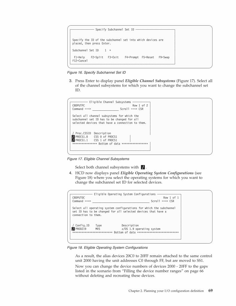
3. Press Enter to display panel Eligible Channel Subsystems (Figure 17). Select allof the channel subsystems for which you want to change the subchannel setID.
Select both channel subsystems with �/�.4. HCD now displays panel Eligible Operating System Configurations (see
Figure 18) where you select the operating systems for which you want tochange the subchannel set ID for selected devices.
As a result, the alias devices 20C0 to 20FF remain attached to the same controlunit 2000 having the unit addresses C0 through FF, but are moved to SS1.Now you can change the device numbers of devices 2000 - 20FF to the gapslisted in the scenario from “Filling the device number ranges” on page 66without deleting and recreating these devices.
┌─────────────── Specify Subchannel Set ID ─────────────────────────┐│ ││ ││ Specify the ID of the subchannel set into which devices are ││ placed, then press Enter. ││ ││ Subchannel Set ID 1 + ││ ││ F1=Help F2=Split F3=Exit F4=Prompt F5=Reset F9=Swap ││ F12=Cancel │└───────────────────────────────────────────────────────────────────┘
Figure 16. Specify Subchannel Set ID
┌─────────── Eligible Channel Subsystems ───────────┐│ CBDPUTPC Row 1 of 2 ││ Command ===> _________________ Scroll ===> CSR ││ ││ Select all channel subsystems for which the ││ subchannel set ID has to be changed for all ││ selected devices that have a connection to them. ││ ││ ││ / Proc.CSSID Description ││�/�PROCS1.0 CSS 0 of PROCS1 ││�/�PROCS1.1 CSS 1 of PROCS1 ││ **************** Bottom of data ***************** ││ │└───────────────────────────────────────────────────┘
Figure 17. Eligible Channel Subsystems
┌────────────── Eligible Operating System Configurations ───────────────┐│ CBDPUTOC Row 1 of 1 ││ Command ===> _____________________________________ Scroll ===> CSR ││ ││ Select all operating system configurations for which the subchannel ││ set ID has to be changed for all selected devices that have a ││ connection to them. ││ ││ ││ / Config.ID Type Description ││�/�PRODZ19 MVS z/OS 1.9 operating system ││ ************************** Bottom of data *************************** ││ │└───────────────────────────────────────────────────────────────────────┘
Figure 18. Eligible Operating System Configurations
Chapter 2. Planning your I/O configuration definition 69
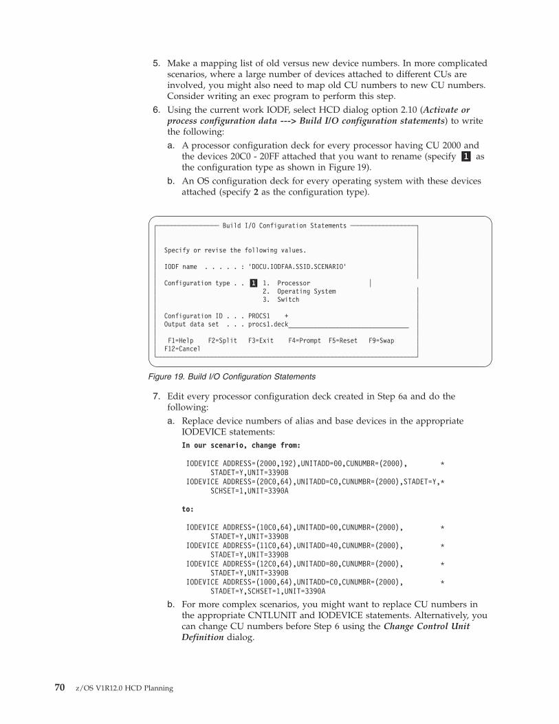
5. Make a mapping list of old versus new device numbers. In more complicatedscenarios, where a large number of devices attached to different CUs areinvolved, you might also need to map old CU numbers to new CU numbers.Consider writing an exec program to perform this step.
6. Using the current work IODF, select HCD dialog option 2.10 (Activate orprocess configuration data ---> Build I/O configuration statements) to writethe following:a. A processor configuration deck for every processor having CU 2000 and
the devices 20C0 - 20FF attached that you want to rename (specify �1� asthe configuration type as shown in Figure 19).
b. An OS configuration deck for every operating system with these devicesattached (specify 2 as the configuration type).
7. Edit every processor configuration deck created in Step 6a and do thefollowing:a. Replace device numbers of alias and base devices in the appropriate
IODEVICE statements:In our scenario, change from:
IODEVICE ADDRESS=(2000,192),UNITADD=00,CUNUMBR=(2000), *STADET=Y,UNIT=3390B
IODEVICE ADDRESS=(20C0,64),UNITADD=C0,CUNUMBR=(2000),STADET=Y,*SCHSET=1,UNIT=3390A
to:
IODEVICE ADDRESS=(10C0,64),UNITADD=00,CUNUMBR=(2000), *STADET=Y,UNIT=3390B
IODEVICE ADDRESS=(11C0,64),UNITADD=40,CUNUMBR=(2000), *STADET=Y,UNIT=3390B
IODEVICE ADDRESS=(12C0,64),UNITADD=80,CUNUMBR=(2000), *STADET=Y,UNIT=3390B
IODEVICE ADDRESS=(1000,64),UNITADD=C0,CUNUMBR=(2000), *STADET=Y,SCHSET=1,UNIT=3390A
b. For more complex scenarios, you might want to replace CU numbers inthe appropriate CNTLUNIT and IODEVICE statements. Alternatively, youcan change CU numbers before Step 6 using the Change Control UnitDefinition dialog.
┌───────────────── Build I/O Configuration Statements ──────────────────┐│ ││ ││ Specify or revise the following values. ││ ││ IODF name . . . . . : ’DOCU.IODFAA.SSID.SCENARIO’ ││ ││ Configuration type . . �1� 1. Processor ││ 2. Operating System ││ 3. Switch ││ ││ Configuration ID . . . PROCS1 + ││ Output data set . . . procs1.deck_________________________________ ││ ││ F1=Help F2=Split F3=Exit F4=Prompt F5=Reset F9=Swap ││ F12=Cancel │└───────────────────────────────────────────────────────────────────────┘
Figure 19. Build I/O Configuration Statements
70 z/OS V1R12.0 HCD Planning
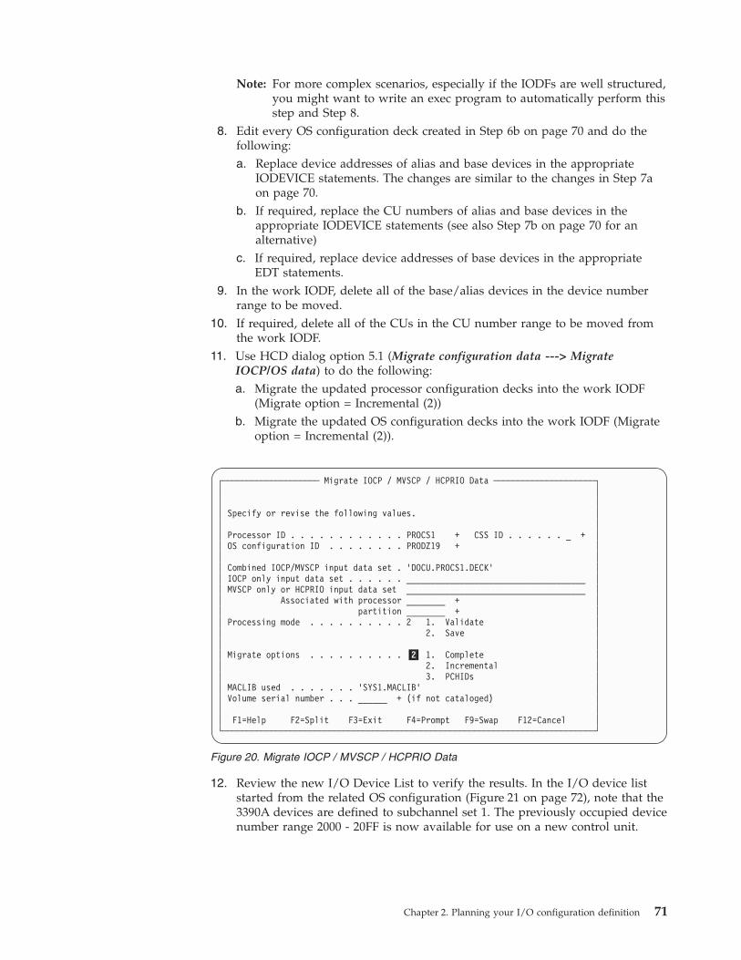
Note: For more complex scenarios, especially if the IODFs are well structured,you might want to write an exec program to automatically perform thisstep and Step 8.
8. Edit every OS configuration deck created in Step 6b on page 70 and do thefollowing:a. Replace device addresses of alias and base devices in the appropriate
IODEVICE statements. The changes are similar to the changes in Step 7aon page 70.
b. If required, replace the CU numbers of alias and base devices in theappropriate IODEVICE statements (see also Step 7b on page 70 for analternative)
c. If required, replace device addresses of base devices in the appropriateEDT statements.
9. In the work IODF, delete all of the base/alias devices in the device numberrange to be moved.
10. If required, delete all of the CUs in the CU number range to be moved fromthe work IODF.
11. Use HCD dialog option 5.1 (Migrate configuration data ---> MigrateIOCP/OS data) to do the following:a. Migrate the updated processor configuration decks into the work IODF
(Migrate option = Incremental (2))b. Migrate the updated OS configuration decks into the work IODF (Migrate
option = Incremental (2)).
12. Review the new I/O Device List to verify the results. In the I/O device liststarted from the related OS configuration (Figure 21 on page 72), note that the3390A devices are defined to subchannel set 1. The previously occupied devicenumber range 2000 - 20FF is now available for use on a new control unit.
┌──────────────────── Migrate IOCP / MVSCP / HCPRIO Data ─────────────────────┐│ ││ ││ Specify or revise the following values. ││ ││ Processor ID . . . . . . . . . . . . PROCS1 + CSS ID . . . . . . _ + ││ OS configuration ID . . . . . . . . PRODZ19 + ││ ││ Combined IOCP/MVSCP input data set . ’DOCU.PROCS1.DECK’ ││ IOCP only input data set . . . . . . _____________________________________ ││ MVSCP only or HCPRIO input data set _____________________________________ ││ Associated with processor ________ + ││ partition ________ + ││ Processing mode . . . . . . . . . . 2 1. Validate ││ 2. Save ││ ││ Migrate options . . . . . . . . . . �2� 1. Complete ││ 2. Incremental ││ 3. PCHIDs ││ MACLIB used . . . . . . . ’SYS1.MACLIB’ ││ Volume serial number . . . ______ + (if not cataloged) ││ ││ F1=Help F2=Split F3=Exit F4=Prompt F9=Swap F12=Cancel │└─────────────────────────────────────────────────────────────────────────────┘
Figure 20. Migrate IOCP / MVSCP / HCPRIO Data
Chapter 2. Planning your I/O configuration definition 71
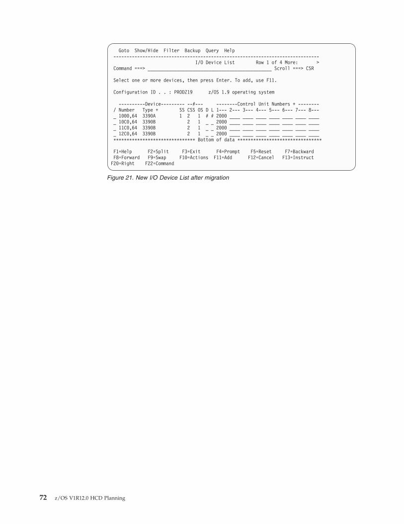
Goto Show/Hide Filter Backup Query Help------------------------------------------------------------------------------
I/O Device List Row 1 of 4 More: >Command ===> _______________________________________________ Scroll ===> CSR
Select one or more devices, then press Enter. To add, use F11.
Configuration ID . . : PRODZ19 z/OS 1.9 operating system
----------Device--------- --#--- --------Control Unit Numbers + --------/ Number Type + SS CSS OS D L 1--- 2--- 3--- 4--- 5--- 6--- 7--- 8---_ 1000,64 3390A 1 2 1 # # 2000 ____ ____ ____ ____ ____ ____ _____ 10C0,64 3390B 2 1 _ _ 2000 ____ ____ ____ ____ ____ ____ _____ 11C0,64 3390B 2 1 _ _ 2000 ____ ____ ____ ____ ____ ____ _____ 12C0,64 3390B 2 1 _ _ 2000 ____ ____ ____ ____ ____ ____ ____******************************* Bottom of data ********************************
F1=Help F2=Split F3=Exit F4=Prompt F5=Reset F7=BackwardF8=Forward F9=Swap F10=Actions F11=Add F12=Cancel F13=InstructF20=Right F22=Command
Figure 21. New I/O Device List after migration
72 z/OS V1R12.0 HCD Planning
Chapter 3. Specifying an I/O configuration at IPL
You must specify your I/O configuration definition at IPL— during initial install,upgrade, and recovery.
Defining your initial I/O configurationYou define your initial I/O configuration in the following situations:v You could be installing z/OS for the first time. In which case, you would have a
bootstrap system, consisting of an install IOCP (stand-alone IOCP) and abootstrap z/OS. This would require an initial "bootstrap" POR and probably IPL.
v You could be using IODFs for the first time and want to use dynamicconfiguration capability. In this case, you could run HCD and create the IODF.Do a POR to get the active IOCDS token in the HSA. See “Ensuring that thesoftware and hardware definitions match” on page 6 for information aboutconfiguration tokens.
Each time you install a new processor that does not have an IOCDS yet, you canuse HCD to build an IOCP input data set. Then you can transfer this data set totape and run the IOCP stand alone program that is installed in your processor.
Take the following general actions to define your configuration at IPL:1. Create I/O software configuration plan.
See Chapter 2, “Planning your I/O configuration definition,” on page 11.2. Install your I/O devices.
See device guides for information about devices.3. Install z/OS, which includes HCD.
See z/OS Program Directory and z/OS HCD User's Guide.4. Install software support for IBM equipment.
The UIM points to other device support information provided with theproduct. See program directories for IBM products such as DFSMS or VirtualTelecommunications Access Method (VTAM).
5. Provide and/or install software support for devices not supported by z/OS.See z/OS MVS Device Validation Support.
6. Determine whether to authorize access to making dynamic configurationchanges. The security administrator can use RACF to authorize operators andHCD users to activate dynamic changes. Before anyone can use either theACTIVATE command or the HCD Activate New Configuration panel, thesecurity administrator must give that user UPDATE authority to theMVS.ACTIVATE resource in the OPERCMDS class. (See z/OS MVS Planning:Operations.)
7. To handle data sets that are cataloged with an esoteric name, do one of thefollowing:v Specify a token for the esoterics. Allocation uses the esoteric token to find
the appropriate esoteric for a data set that has been cataloged usingesoterics. You no longer have to keep the esoterics in the same sequenceand can delete and add esoterics without having problems accessing datasets that are cataloged using esoterics.
© Copyright IBM Corp. 1989, 2010 73
v Recatalog the data sets with a generic device type name (for example, 3380)before using HCD to migrate IOCP/MVSCP data.
8. Invoke HCD.You start HCD like any other ISPF application in your TSO/E system. Thedefault TSO/E CLIST that is supplied with HCD is CBDCHCD (whichinvokes CBDCHCD1) in library SYS1.SCBDCLST.See z/OS HCD User's Guide for more information, including which functionsare available as batch utilities and thus do not require ISPF.
9. Use HCD to define your configuration:a. Create a work IODF by either migrating MVSCP/IOCP decks with the
HCD panels or migration batch facility or updating an existing IODF.
Note: If you are not using dynamic capability, sometimes you cananticipate I/O configuration changes. For example, you might knowthat a control unit and associated DASDs will be installed but arenot installed when z/OS is IPLed. Two possible methods of addingthe control unit and the DASD are:
v Define the control unit and DASD to both the hardware and thesoftware before devices are installed. This strategy saves a POR and IPLwhen the physical control unit and DASD are installed. However, theinactive UCBs waste storage until devices are installed.
v Define the control unit and DASD only to the hardware before devicesare installed. During POR, hardware definitions of the devices are built.When the control unit and DASD are installed, create the softwaredefinition, then IPL z/OS with the new software definition to make thedevices available. This strategy saves a POR.
b. Create a production IODF from the work IODF.See z/OS HCD User's Guide for information about creating IODFs.You do not need to pre-allocate an IODF; you allocate it through HCD, and itresides on the volume you specify through HCD.You specify an EDT identifier and create an EDT as part of defining yourconfiguration in HCD. You also specify an operating system configurationidentifier.
10. Create the LOADxx member in which you specify an IODF statement toidentify the I/O configuration definition for IPL.An IODF statement contains the name of the production IODF and identifierof the EDT and operating system configuration that is used to IPL the system.The IODF identified becomes the active IODF for the system.The Load Parameter Definition (8 byte field) on the SYSCTL or OPRCTLframe on ES/9000 processors tells which LOADxx member to use.See “IODF processing at IPL” on page 76 for more information.
11. Specify the configuration to the hardware.Use HCD to run IOCP to create I/O configuration data sets (IOCDSs). Tocreate IOCDSs, you can also use IOCP directly without using HCD, but thendynamic capability will not be available. See IOCP User's Guide.
12. Unless you are running on a z890, z900, or later processor, you must specifythe HSA and MIF expansion requirements for any future dynamic changes atPOR. To enable dynamic I/O configuration changes, you must also indicatethat you want to allow dynamic modifications. You specify this information inthe Activation Reset profiles.
74 z/OS V1R12.0 HCD Planning
If you expect to make dynamic configuration changes, you must specify apercent of expansion for the size of HSA. (See Enterprise System/9000 OperatorGuide .) You indicate the percent increase of existing HSA size. A 10%expansion factor will allow 10% more devices and control units. For example,when you have ten devices and want to add 2 devices, you specify 20 percentexpansion.The amount of HSA storage that the channel subsystem requires depends on:v The configuration definition (the number of devices, control units, and
channel paths defined in the IOCDS) used for the PORv The processor model and microcode levelThere is an HSA option on the DISPLAY IOS,CONFIG command that displaysthe amount of HSA remaining for dynamic changes. For a description, seez/OS MVS System Commands.You can only increase the HSA expansion percentage by performing anotherPOR.Unless you are running on a z900, z890, or later processor, you also need tospecify the expansion factor for MIF. For prior processors, indicate thepercentage of the expansion that is for shared devices. For example, if youspecify 50 percent, half the expanded HSA will be used for additional shareddevices and the other half for additional unshared devices. If you specify 100percent, all the expanded HSA will be used for additional shared devices. Seethe processor manuals for more information.On a z890, z900, or later processor, you do not specify HSA and MIFexpansion percentages. Instead, specify the maximum number of devices thatyou will want to access. When you define each logical channel subsystem, thisvalue replaces the HSA and MIF expansion requirements. This number shouldtake into account any changes you may want to make in the future. You canspecify up to 63K devices.
13. Do a POR to initialize the channel subsystem/HSA from an IOCDS created byHCD.When you go to make changes to your configuration, tokens in the currentIODF and HSA must match in order to make hardware changes. To get thematching token in the HSA, you have to perform a POR with an IOCDScreated by HCD. The IOCDS must contain a hardware configuration definitionincluded with the current IODF.
14. When specifying system parameters for IPL, use the SQA parameter in theIEASYSxx member of SYS1.PARMLIB to define estimated additional storagefor UCBs that will be added by future dynamic changes. System parameterscan be specified either in the IEASYSxx member of SYS1.PARMLIB or asoperator responses to IPL messages.At IPL the system determines from the current I/O configuration how muchSQA and ESQA to use to represent the UCBs for the I/O configuration beingIPLed. This amount of SQA and ESQA storage is then increased by theamount that you request on the SQA parameter in the IEASYSxx member ofSYS1.PARMLIB. (See z/OS MVS Initialization and Tuning Reference.)You must ensure that there is also enough system queue area (SQA) storagefor any devices that are to be dynamically added to a configuration. A UCBon average needs 112 (hex) bytes of storage below 16 megabytes and 88 (hex)bytes above 16 megabytes.When you dynamically add UCBs, the system obtains storage for these newUCBs from the SQA allotment. For example, if you add 10 devices to your
Chapter 3. Specifying an I/O configuration at IPL 75
|||
configuration, the system obtains about AB4 (hex)/2740 (decimal) bytes ofSQA and 550 (hex)/1360 (decimal) bytes of extended system queue (ESQA) forthe new UCBs.
Note: If your installation needs to dynamically change between differentconfigurations, in which few or none of the devices are the same, yourinstallation must ensure there is enough SQA for the largestconfiguration and for the next largest configuration to be used. z/OSneeds enough storage for all the UCBs in the current configuration andall the new and changed UCBs in the replacement configuration. Ifthere is a problem during activation of the replacement configuration,z/OS needs this storage to recover and reestablish the UCBs thatexisted before the attempt to change the configuration.
15. When specifying system parameters for IPL, use the CMB parameter to defineestimated additional storage for channel measurement blocks (CMBs) that willbe added by future dynamic changes. System parameters can be specifiedeither in the IEASYSxx member of SYS1.PARMLIB or as operator responses toIPL messages.A channel measurement block accumulates measurement data for I/O devices.You need to specify, on the CMB parameter in the IEASYSxx member ofSYS1.PARMLIB, the sum of the number of I/O devices that you need tomeasure that are not DASD or tape (or other types of devices specified usingthe CMB options) plus the number of devices that you plan to dynamicallyadd and measure. (See z/OS MVS Initialization and Tuning Reference.)To determine the number of devices that the system can measure during agiven IPL, the system calculates the sum of the following:v Number of DASD devices in the I/O configuration definition that you
selected at IPLv Number of tape devices in the I/O configuration definition that you
selected at IPLv Value that you specified on the CMB parameter.Therefore, when you define the CMB parameter, remember that the systemallocates CMB space for the DASD and tape devices contained in the I/Oconfiguration definition that you select at IPL.If you have z890/z990 exploitation support installed on your system, thesystem ignores the CMB (channel measurement blocks) parameter in theIEASYSxx parmlib member. z/OS dynamically allocates enough space toaccommodate the number of devices in use, up to the maximum number ofdevices possible.
16. Initialize z/OS with the production IODF and select the appropriate LOADxxmember for the configuration. See “IODF processing at IPL” for moreinformation.
IODF processing at IPLWhen you perform an IPL, the production IODF that defines the configuration tothe system is selected and used. This IODF is selected from any number of otherIODFs. You identify the IODF by the IODF statement in the LOADxx member ofSYSn.IPLPARM or SYS1.PARMLIB PDS.
To identify the IODF selected at IPL, do the following:1. Identify the IODF volume. An IODF volume is the direct access storage device
(DASD) on which you place your IODFs. You identify the IODF volume on theLOAD parameter on the operator control (OPRCTL) or system control
76 z/OS V1R12.0 HCD Planning
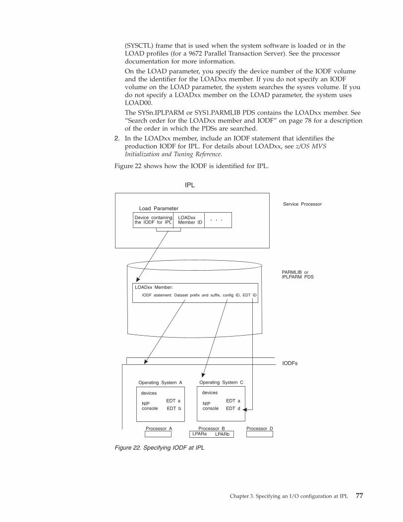
(SYSCTL) frame that is used when the system software is loaded or in theLOAD profiles (for a 9672 Parallel Transaction Server). See the processordocumentation for more information.On the LOAD parameter, you specify the device number of the IODF volumeand the identifier for the LOADxx member. If you do not specify an IODFvolume on the LOAD parameter, the system searches the sysres volume. If youdo not specify a LOADxx member on the LOAD parameter, the system usesLOAD00.The SYSn.IPLPARM or SYS1.PARMLIB PDS contains the LOADxx member. See“Search order for the LOADxx member and IODF” on page 78 for a descriptionof the order in which the PDSs are searched.
2. In the LOADxx member, include an IODF statement that identifies theproduction IODF for IPL. For details about LOADxx, see z/OS MVSInitialization and Tuning Reference.
Figure 22 shows how the IODF is identified for IPL.
IPL
Load Parameter
Device containingthe IODF for IPL
LOADxxMember ID
LOADxx Member:
IODF statement: Dataset prefix and suffix, config ID, EDT ID
PARMLIB orIPLPARM PDS
IODFs
Operating System A Operating System C
devices devices
NIPconsole
NIPconsole
EDT aEDT a
EDT b EDT d
Processor BProcessor A Processor DLPARa LPARb
Service Processor
. . .
Figure 22. Specifying IODF at IPL
Chapter 3. Specifying an I/O configuration at IPL 77
You can have multiple operating system and processor configurations in one IODF.The configurations can share common device definitions. In the IODF shown in theexample, the configurations for operating system A and operating system C shareEDT a.
IODF statement in the LOADxx memberA production IODF name has the following syntax:
<IODF-prefix>.IODF<IODF-suffix>
An example of a production IODF name is SYS2.IODF01.
You can specify the IODF prefix and suffix in the LOADxx statement to identifythe production IODF at IPL. The IODF statement in the LOADxx member cancontain the following information:v IODF suffix
The IODF suffix is the two digit hexadecimal number that is part of the IODFname. For example, “01” is the IODF suffix for IODF01.
v IODF prefixThe IODF prefix is an 8-byte high-level qualifier of the IODF data set name. Forexample, IBMCONF is the IODF prefix for the IODF data set IBMCONF.IODF01.
v Operating system (OS) configuration identifierThe 8-byte operating system configuration identifier is part of the configurationdefinition in the IODF; it identifies the operating system configuration.
v Eligible device table (EDT) identifierThe EDT identifier is the two digit hexadecimal number that identifies the EDTfor use with the configuration defined by the IODF. If you do not specify anEDT identifier, it defaults to “00.”
v LOAD optionThe LOAD option is a field where you indicate if the system will load devicesupport code for every UIM whether a device of that type is installed or not. Ifyou leave the field blank or specify Y, the system loads all the device supportmodules for the devices in the IODF and all device types that support dynamicconfiguration for which you have UIMs installed. This option enables you toadd device types dynamically that were not in the IODF at IPL. When youspecify any other character, the system loads only the modules required for thedevices defined in your current IODF.
Search order for the LOADxx member and IODFDuring IPL, the system uses the LOADxx member that it finds first whensearching in the following order:1. The system first searches the IODF volume for a SYSn.IPLPARM PDS where n
is 0 through 9.2. If it does not find SYSn.IPLPARM, it searches the IODF volume for a
SYS1.PARMLIB PDS.3. If it does not find SYS1.PARMLIB on the IODF volume, it searches for
SYS1.PARMLIB on the sysres volume.Specifying the IODF on the sysres volume is not recommended for thefollowing reasons:v It is difficult to replicate the sysres volume if it contains an IODF because an
IODF is a VSAM data set.v When you share the sysres volume across multiple systems, I/O contention
occurs when the systems are IPLed. Having the IODF on the sysres volumeadds to the contention.
78 z/OS V1R12.0 HCD Planning
The LOADxx member may reside on either the IODF volume or the SYSRESvolume.
If z/OS finds SYSn.IPLPARM or SYS1.PARMLIB, but it doesn't contain theLOADxx member in the LOAD parameter, z/OS enters a wait state.
Because the system data sets are searched in order, IBM suggests usingSYS0.IPLPARM for improved IPL performance.
Specifying the IODF high-level qualifier: If LOADxx is in SYS1.PARMLIB, youmust specify an IODF high-level qualifier in the IODF statement. If the LOADxxmember is in SYSn.IPLPARM and the IODF statement does not contain ahigh-level qualifier, z/OS defaults to the high-level qualifier of theSYSn.IPLPARM.PDS.
If you optionally specify equals (========) as the IODF high-level qualifier in theIODF statement, z/OS attempts to use the high-level qualifier from the hardwareconfiguration token in the HSA. If the token is not available, z/OS loads wait stateX'0B1', with reason code X'00B'. If the high-level qualifier found in the hardwareconfiguration token contains a blank in the first character, z/OS loads wait stateX'0B1', with reason code X'009'.
Specifying the IODF suffix: You can optionally specify an IODF suffix andoperating system configuration ID in the IODF statement in LOADxx, or you canlet z/OS find the correct IODF automatically. This automatic search saves you fromhaving to change the LOADxx member every time you switch IODFs. Howeveryou might have to rename the suffix of the IODF so that z/OS will find it first inits search sequence.
The IODF search options (++, −−, ==, **, and ��(blank blank)) provide flexibility inIODF management. You can set up LOADxx so that you do not have to change it,following every dynamic configuration and IOCDS update, for use at the next IPL.Users, who want to maintain a back up IODF on a second volume in case ofdevice failure, can use the flexible searching algorithm. This allows the backupIODF name to have the next larger or lower sequential number as a suffix.
Table 6 on page 80 describes the options you can use when identifying the IODFand operating system configuration ID for IPLing the system.
When you specify asterisks, pluses, minuses, or equals as the IODF suffix, z/OSuses the IODF name in the hardware configuration token in the HSA. If youoverride the descriptor fields (when building a production IODF using HCDpanels) and specify an invalid IODF name, the token in the HSA is unusable. Inthis situation, z/OS searches for a valid production IODF as follows:v For '**' and '++', z/OS searches suffixes X'00' to X'FF' for a valid IODFv For '−−', z/OS searches suffixes X'FF' to X'00' for a valid IODFv For '==', z/OS loads wait state X'0B1', with reason code X'00B'
Attention: If you are specifying asterisks, equals, pluses, or minuses for theIODF suffix in LOADxx, never change the default descriptor field values on theHCD panel when you create a production IODF because z/OS uses thisinformation to find the current IODF. Also, make it a policy to always write a newIOCDS after a dynamic configuration change.
Chapter 3. Specifying an I/O configuration at IPL 79
||
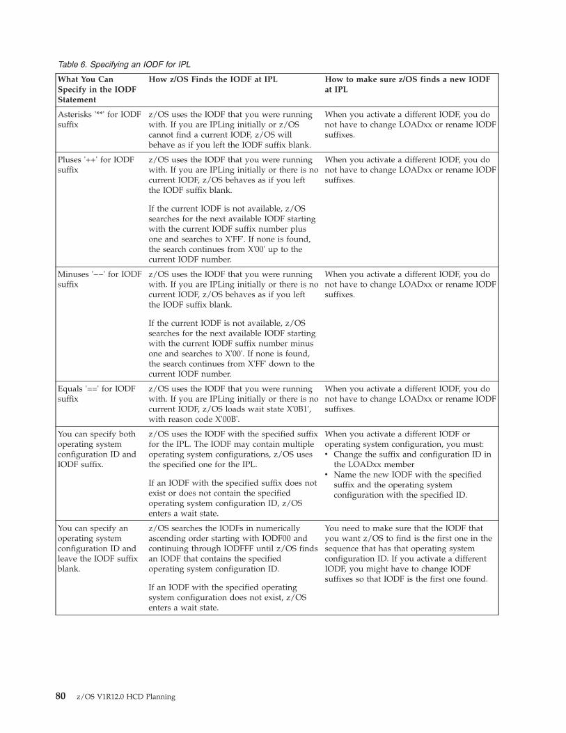
Table 6. Specifying an IODF for IPL
What You CanSpecify in the IODFStatement
How z/OS Finds the IODF at IPL How to make sure z/OS finds a new IODFat IPL
Asterisks '**' for IODFsuffix
z/OS uses the IODF that you were runningwith. If you are IPLing initially or z/OScannot find a current IODF, z/OS willbehave as if you left the IODF suffix blank.
When you activate a different IODF, you donot have to change LOADxx or rename IODFsuffixes.
Pluses '++' for IODFsuffix
z/OS uses the IODF that you were runningwith. If you are IPLing initially or there is nocurrent IODF, z/OS behaves as if you leftthe IODF suffix blank.
If the current IODF is not available, z/OSsearches for the next available IODF startingwith the current IODF suffix number plusone and searches to X'FF'. If none is found,the search continues from X'00' up to thecurrent IODF number.
When you activate a different IODF, you donot have to change LOADxx or rename IODFsuffixes.
Minuses '−−' for IODFsuffix
z/OS uses the IODF that you were runningwith. If you are IPLing initially or there is nocurrent IODF, z/OS behaves as if you leftthe IODF suffix blank.
If the current IODF is not available, z/OSsearches for the next available IODF startingwith the current IODF suffix number minusone and searches to X'00'. If none is found,the search continues from X'FF' down to thecurrent IODF number.
When you activate a different IODF, you donot have to change LOADxx or rename IODFsuffixes.
Equals '==' for IODFsuffix
z/OS uses the IODF that you were runningwith. If you are IPLing initially or there is nocurrent IODF, z/OS loads wait state X'0B1',with reason code X'00B'.
When you activate a different IODF, you donot have to change LOADxx or rename IODFsuffixes.
You can specify bothoperating systemconfiguration ID andIODF suffix.
z/OS uses the IODF with the specified suffixfor the IPL. The IODF may contain multipleoperating system configurations, z/OS usesthe specified one for the IPL.
If an IODF with the specified suffix does notexist or does not contain the specifiedoperating system configuration ID, z/OSenters a wait state.
When you activate a different IODF oroperating system configuration, you must:v Change the suffix and configuration ID in
the LOADxx memberv Name the new IODF with the specified
suffix and the operating systemconfiguration with the specified ID.
You can specify anoperating systemconfiguration ID andleave the IODF suffixblank.
z/OS searches the IODFs in numericallyascending order starting with IODF00 andcontinuing through IODFFF until z/OS findsan IODF that contains the specifiedoperating system configuration ID.
If an IODF with the specified operatingsystem configuration does not exist, z/OSenters a wait state.
You need to make sure that the IODF thatyou want z/OS to find is the first one in thesequence that has that operating systemconfiguration ID. If you activate a differentIODF, you might have to change IODFsuffixes so that IODF is the first one found.
80 z/OS V1R12.0 HCD Planning
Table 6. Specifying an IODF for IPL (continued)
What You CanSpecify in the IODFStatement
How z/OS Finds the IODF at IPL How to make sure z/OS finds a new IODFat IPL
You can specify anIODF suffix and leavethe operating systemconfiguration ID blank
z/OS uses the IODF with the specified suffixas long as that IODF only contains a singleOS configuration.
If that IODF contains more than oneoperating system configuration, z/OS entersa wait state.
When you activate a different IODF, youmust do one of the following:v Change the suffix in the LOADxx memberv Name the new IODF with that suffix.
You can leave boththe operating systemconfiguration ID andIODF suffix blank
z/OS uses the IODF that it finds bysearching in numerically ascending orderstarting with IODF00 for the first IODF thatcontains a single operating systemconfiguration ID.
If you activate a different IODF, you do nothave to change the LOADxx member butyou do have to make sure that the new IODFwill be the first one that z/OS finds byrenaming the IODFs.
Note: If you specify asterisks, pluses, minuses, or equals, for the IODF suffix, do not change the default values forthe descriptor fields when you create a production IODF. z/OS uses the default information to find the IODF.
If you do not specify an '**', '++', '−−', or '==' for the IODF suffix, when z/OS findsthe IODF, it checks whether the IODF contains a hardware I/O configurationdefinition that matches the representation used by the channel subsystem. Whetherit matches determines the kind of configuration changes you can make. If it doesmatch, you can change both hardware and software definitions. If it does notmatch, you can make only software configuration changes. To enable changes tothe hardware configuration definition, you can make a software-only dynamicchange that activates an IODF containing the correct hardware I/O configurationdefinition.
Specifying an operating system configuration ID: If you also specify anoperating system configuration ID in the IODF statement, the IODF may containmultiple operating system configurations and z/OS uses the specified one. If youdo not specify an operating system configuration, then the IODF should containonly one operating system configuration. If the IODF contains more than oneoperating system configuration, z/OS enters a wait state.
Specifying the EDT identifier: If you are letting z/OS find the correct IODFautomatically and you do not specify an EDT identifier, z/OS uses '00' as theidentifier. To ensure that an IODF with the identified EDT exists, you can eitherspecify an EDT identifier and put that EDT in each IODF or put an EDT with a '00'identifier in each IODF.
Using your initial I/O configuration with special secondary(3390D) devices for reIPL
If special secondary (3390D) devices are used in subchannel set 1, the operatingsystem must determine whether the IPL has occurred after a HyperSwap® thatmight have switched devices from the PPRC primary devices to the PPRCsecondary devices. If so, the IPL can still use the initial I/O configurationdefinition, but must initialize using the correct set of devices as primaries andsecondaries.
In the LOADxx parmlib member, the SCHSET parameter allows you to specifywhether the special secondary (3390D) devices in subchannel set 1 are to be usedas the primary devices for the IPL or the initial primary devices in subchannel set
Chapter 3. Specifying an I/O configuration at IPL 81
0 are to be used. When SCHSET is set to "1," the initial PPRC special secondarydevices are brought online as the new PPRC primary devices and the initial PPRCprimary devices will remain offline as the new PPRC special secondary devices.
For information on specifying the SCHSET parameter of LOADxx, see z/OS MVSInitialization and Tuning Reference, SA22-7592.
Defining your I/O configuration for reIPLDefining a configuration for reIPL is an exception or recovery task. The only timesyou would not perform a dynamic change are:v When you are installing a device that does not support dynamic capabilityv When you are installing a new product and no device code for it is residentv When you need to reIPL the system after a system outage
Take the following general actions to define your configuration at reIPL:1. Reconsider the SQA and CMB parameter values in case they need to be
increased due to additional devices being added to the configuration.2. Update or create the LOADxx member so the new production IODF will be
selected at IPL. This step is optional if you let the system find it by notspecifying the IODF suffix. If you specify '**', '++', '−−', or '==' for the IODFsuffix, z/OS uses the IODF that was the last active IODF. If you use asterisksfor the IODF suffix, make sure that you always write a new IOCDS after adynamic change and that you never change the default values of the descriptorfields when you create a production IODF.
82 z/OS V1R12.0 HCD Planning
Chapter 4. Dynamically changing an I/O configuration
HCD allows you to change an I/O configuration dynamically, that is, without anIPL or POR.
Before attempting to change an I/O configuration dynamically, ensure that yoursystem has migrated to dynamic capability. Until your installation updates itsaffected application programs or installs updated products to support dynamicconfiguration, you should define any devices that support dynamic configurationas installation-static, so that the programs that do not support dynamicconfiguration can continue to use the devices.
For migration information, see “Migrating to the dynamic capability provided withHCD” on page 113.
Actions to change your configuration dynamicallyDefining a configuration dynamically involves the following tasks:1. Verify that each I/O device that you plan to delete is not needed by any
application or logical partition by varying the I/O device offline.2. Check that the current software I/O configuration definition matches the
hardware I/O configuration.You can check that the definitions match by testing an activation of ahardware and software change. When the activation specifies configurationsthat do not match, the test function displays an error message. For moreinformation about testing an activation, see “Testing dynamic activation” onpage 102.
3. Attempt to change the (current) active production IODF.This action will cause HCD to create a new work IODF.
4. Change the work IODF to define the new I/O configuration.Along with specifying other information about the configuration, you useHCD to define as DYNAMIC “Yes” each device that you want to be able todynamically change. DYNAMIC “Yes” is not required to add a devicedynamically but is required to change or delete it. For more information aboutdefining devices dynamically, “Making dynamic changes to I/O devices” onpage 88.
5. Create a production IODF from the work IODF.6. If desired, physically remove the devices that you are deleting.7. Update or create the LOADxx member so the new production IODF will be
selected at IPL. This step is optional if you let the system find it by notspecifying the IODF suffix. If you specify '**', '++', '− −', or '==' for the IODFsuffix, z/OS uses the IODF that was the last active IODF. If you use asterisks,ensure that you always write a new IOCDS after a dynamic change and thatyou never change the default values of the descriptor fields when you create aproduction IODF. For more information, see “IODF processing at IPL” onpage 76.
8. Optionally, test the configuration before you actually activate it. For moreinformation about testing an activation, see “Testing dynamic activation” onpage 102
9. Activate the new IODF.
© Copyright IBM Corp. 1989, 2010 83
See “Dynamically changing an I/O configuration in LPAR mode” for adescription of activating changes in logical partitions. For a software andhardware dynamic activation, the software and hardware configurations mustmatch. When they match, activation occurs. When they do not match,activation does not occur.See “Dynamically changing an I/O configuration in a sysplex” on page 87 forplanning considerations before you dynamically activate configurations in asysplex.
10. If desired, install the new I/O components.11. Use HCD to write a new IOCDS for the new default IOCDS at the next POR.12. Optionally, use HCD to create a backup copy of the new production IODF in
case you lose your DASD.13. Update the standard configuration list (CONFIGxx) member in
SYS1.PARMLIB to reflect the new configuration definition.You can use the configuration defined in CONFIGxx to compare thedifferences between the current configuration and the standard configurationas defined in a CONFIGxx member. When the operator issues the DISPLAYcommand with the M=CONFIG(xx) option, the system displays anydifferences.Enter the DISPLAY command (D M=CONFIG(xx)) to view any differencescaused by the dynamic configuration change and update the CONFIGxxmember to reflect the new definition. For descriptions of the statements andparameters of CONFIGxx, see z/OS MVS Initialization and Tuning Reference.
14. You can also use HCD to build the CONFIGxx member from a configurationin the IODF, and to process the DISPLAY M=CONFIG(xx) command. For moreinformation, see z/OS HCD User's Guide.
15. Use HCD to create a stand-alone IOCP input tape for ES/9000 PCE recoverysupport.The tape can be used for recovery if you lose the disk holding the IOCDS inthe processor controller. For a description of creating an IOCP input data set,see z/OS HCD User's Guide.
Related information:v For more information for the type of I/O component you are defining, see
“Dynamically changing component definitions” on page 88.v For the recovery steps to take if your system fails during a dynamic
configuration change, see “Recovery during dynamic configuration” on page103.
Dynamically changing an I/O configuration in LPAR modeWhen a processor is running in LPAR mode, any single logical partition can makedynamic configuration changes that affect the hardware configuration for all theother logical partitions. To eliminate unwanted disruption across logical partitions(to not delete hardware I/O components that are in use by another logicalpartition), you must follow these steps:1. In all logical partitions except one, use HCD panels to make software-only
changes. (See “Making software-only dynamic changes” on page 8.) Think ofthe software only changes in these partitions as step 1. In the HCD panels,activate the “software definitions only and validate hardware changes” option.
84 z/OS V1R12.0 HCD Planning
You can also use the ACTIVATE command with the SOFT option. See z/OSMVS System Commands. As you make the software-only changes to each logicalpartition, the system validates that the I/O components being deleted are notin use.If you are certain that a dynamic configuration change will not affect aparticular logical partition, you do not need to make software-only changes tothat logical partition.
2. In the remaining one logical partition, use HCD panels to make both hardwareand software changes. (See “Making both hardware and software dynamicchanges” on page 8.) Think of the hardware and software change in thisremaining partition as step 2. In the HCD panels, activate “hardware andsoftware definitions”. You can also use the ACTIVATE command and omit theSOFT option.
Dynamic I/O configuration considerationsConsider the following when making dynamic I/O configuration changes:v Ensuring that you activate the correct IODF in Step 1: When you make
dynamic changes to coupling facility devices and control units be careful toactivate the correct IODF in step 1. If you activate an incorrect IODF and thesystem displays message IOS500I or IOS1500I with a note indicating that theIODF does not contain a configuration definition that matches the currenthardware definition, you must perform the following steps:1. In the step 1 partition, activate the previous IODF to reset the configuration
definition to its previous state.2. In the step 1 partition, activate the correct IODF.3. In the step 2 partition, perform the software and hardware change.If the system does not display the note on the IOS500I or IOS1500I message, youcan activate the correct IODF in the step 1 partition and perform the softwareand hardware change in the step 2 partition.
v Dynamic deletion of I/O hardware components requires FORCE: To preventyou from inadvertently deleting I/O components that another logical partition isusing, HCD only allows you to delete I/O components when you specify “Yes”in the “Allow hardware deletes (FORCE)” field on the Activate NewConfiguration panel. An activation that deletes or modifies I/O components mayresult in deletion of a resource - in this case, you must use the FORCEparameter on the activation. See z/OS MVS System Commands.
v Dynamic deletion of I/O and coupling facility hardware components: If youare deleting I/O and coupling facility hardware components that another logicalpartition is using, HCD only allows you to delete I/O components when youspecify “Yes” in the “Allow hardware deletes (FORCE)” field on the ActivateNew Configuration panel. You can also use the ACTIVATE command to eitherdynamically test or activate a new I/O configuration definition. To deletecomponents, use the FORCE attribute on the ACTIVATE command. See z/OSMVS System Commands.
v Dynamic activation in a sysplex that includes a uniprocessor: If you use theACTIVATE command in a sysplex that includes a uniprocessor, that systemmight encounter problems in maintaining XCF synchronization with the rest ofthe sysplex.
Example of deleting an I/O device in LPAR modeFor the sample processor running in LPAR mode shown in Figure 23 on page 86,assume the following:
Chapter 4. Dynamically changing an I/O configuration 85
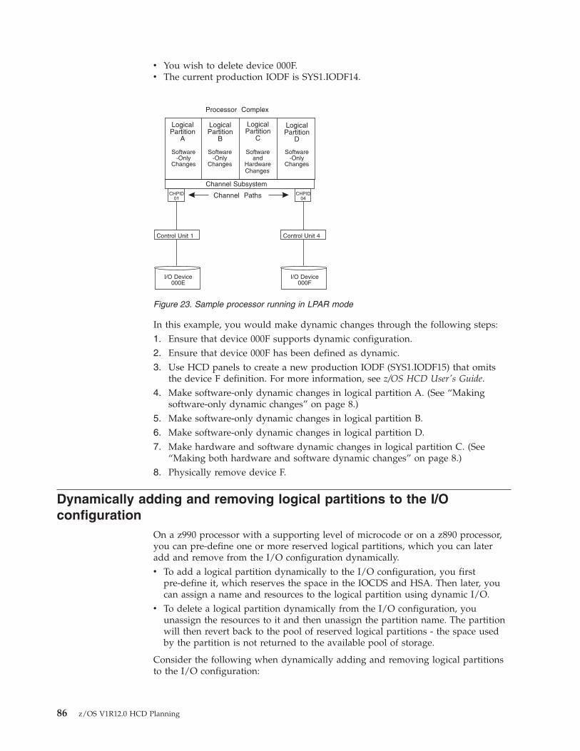
v You wish to delete device 000F.v The current production IODF is SYS1.IODF14.
In this example, you would make dynamic changes through the following steps:1. Ensure that device 000F supports dynamic configuration.2. Ensure that device 000F has been defined as dynamic.3. Use HCD panels to create a new production IODF (SYS1.IODF15) that omits
the device F definition. For more information, see z/OS HCD User's Guide.4. Make software-only dynamic changes in logical partition A. (See “Making
software-only dynamic changes” on page 8.)5. Make software-only dynamic changes in logical partition B.6. Make software-only dynamic changes in logical partition D.7. Make hardware and software dynamic changes in logical partition C. (See
“Making both hardware and software dynamic changes” on page 8.)8. Physically remove device F.
Dynamically adding and removing logical partitions to the I/Oconfiguration
On a z990 processor with a supporting level of microcode or on a z890 processor,you can pre-define one or more reserved logical partitions, which you can lateradd and remove from the I/O configuration dynamically.v To add a logical partition dynamically to the I/O configuration, you first
pre-define it, which reserves the space in the IOCDS and HSA. Then later, youcan assign a name and resources to the logical partition using dynamic I/O.
v To delete a logical partition dynamically from the I/O configuration, youunassign the resources to it and then unassign the partition name. The partitionwill then revert back to the pool of reserved logical partitions - the space usedby the partition is not returned to the available pool of storage.
Consider the following when dynamically adding and removing logical partitionsto the I/O configuration:
LogicalPartition
A
LogicalPartition
B
LogicalPartition
C
LogicalPartition
D
Processor Complex
Channel Subsystem
Channel Paths
I/O Device000E
I/O Device000F
CHPID01
CHPID04
Control Unit 1 Control Unit 4
Software-Only
Changes
Software-Only
Changes
Softwareand
Hardware
Software-Only
ChangesChanges
Figure 23. Sample processor running in LPAR mode
86 z/OS V1R12.0 HCD Planning
v You cannot dynamically remove an active logical partition from the I/Oconfiguration.
v After you assign a name to a partition, you can assign dedicated CHPIDs forthat partition and add the partition to the candidate lists of any reconfigurable,non-managed shared, or spanned CHPIDs. Managed channels do not have to beadded to the candidate list - they are in the candidate list, even unnamed ones,by default.
v Before deleting a logical partition from the I/O configuration by unassigning thepartition name, you must unassign any dedicated CHPIDs defined for thepartition . If there are any reconfigurable, non-managed shared, or spannedCHPIDs defined for the partition, you must remove the partition name from thecandidate list for those CHPIDs.
v When you prepare to delete a logical partition dynamically, if Cryptographiccoprocessors are configured to the logical partition you are trying to delete, thesefeatures must be deconfigured from the LPAR image using the zSeries HardwareManagement Console or Support Element tasks. For more information abouthow to view or change your Cryptographic assignments, see the followingdocumentation for your installed hardware:– Support Element Operations Guide– Processor Resource/Systems Manager™ Planning Guide
v When you delete a logical partition from the I/O configuration dynamically, youdo not have to delete the partition from each device's candidate list , unless youused an explicit candidate list when you defined the device.
Dynamically changing an I/O configuration in a sysplexYou can use HCD as a single point of control to dynamically activate an I/Oconfiguration on one or more systems configured in a sysplex. To determine thesupported processors, run the HCD Supported Hardware Report. For informationabout running reports, see z/OS HCD User's Guide.
Using the “Activate configuration sysplex-wide” option on the HCD Activate andProcess Configuration Data panel, you can make software-only changes as well assoftware and hardware changes to one or more systems from a system in yoursysplex.
Consider the following requirements before you activate your sysplex-wideconfiguration changes:v You can perform a sysplex-wide activation only on a system that is running and
is configured in the sysplex couple data set. For more information about sysplexcouple data sets, see z/OS MVS Setting Up a Sysplex.
v For a sysplex-wide activation to work on a system, the system must allowsoftware configuration changes. To verify that a system allows softwareconfiguration changes, select the “Activate or process configuration data” optionon the HCD Primary Task Selection panel and then the “View activeconfiguration” option on the HCD Activate and Process Configuration Datapanel on that system. HCD displays the currently active IODF, the HSA token,and information about limitations to the activation scope.
After you initiate a sysplex-wide activation, respond to any activation messages.
Chapter 4. Dynamically changing an I/O configuration 87
Dynamically changing component definitionsYou can dynamically add, modify, or delete components in the configuration. Youcan make software and hardware changes or software-only changes. In most cases,you will make simultaneous dynamic configuration changes to both hardware andsoftware configuration definitions. The following sections describe how todynamically change component definitions. For software-only changes, you do nothave to perform all the steps. It is noted when the step is not required for asoftware-only change.
Any dynamic configuration addition, modification, or deletion requires thefollowing two general steps:v Describe the new I/O configuration definition in an I/O definition file (IODF)
that you create through HCD. See z/OS HCD User's Guide.v Activate the new IODF.
You can use either HCD panels or the ACTIVATE command to dynamicallyactivate or test a new I/O configuration definition. Generally, systemprogrammers use HCD and system operators use the ACTIVATE command. Touse HCD panels, see z/OS HCD User's Guide. To use the ACTIVATE command,see z/OS MVS System Commands.
Notes:
1. For software/hardware changes, activate “hardware and softwaredefinitions”. Also, write a new I/O configuration data set (IOCDS) for thenew default IOCDS at the next POR.
2. For software-only changes, activate “software definitions only.” You can alsochoose to “validate hardware changes,” which validates that I/O componentsbeing deleted are not in use.
Additional steps related to specific I/O components are described inv “Making dynamic changes to I/O devices”v “Making dynamic changes to channel paths” on page 92v “Making dynamic changes to control units” on page 95
Coupling facility device and control unit definitions in the IODF are created ordeleted automatically when coupling facility channel paths are connected ordisconnected. See “Making changes to coupling facility devices and control units”on page 97.
Making dynamic changes to I/O devicesYou can dynamically add, modify, or delete device definitions. Remember thatdevices defined as installation-static can still be dynamically added.
Dynamically adding I/O devicesTo dynamically add an I/O device, use the following general steps:1. For each device that you plan to add, ensure that its device support code was
loaded at the last IPL.There are two ways which device support code is loaded at IPL. The choicemade at the last IPL can determine whether the device support code is loadedfor the device that you want to add. Through the IODF statement in theLOADxx member of SYS1.PARMLIB, or SYSn.IPLPARM, for the last IPL, youmight have chosen either of the following:v To load, at IPL, all the dynamic device support code in SYS1.NUCLEUS.
88 z/OS V1R12.0 HCD Planning
This choice, which is the default, allows you to dynamically add any devicethat supports dynamic configuration.
v To load, at IPL, device support code for only those device types defined inthe IODF. This choice allows you to dynamically add only those device typesthat were defined in the IODF.If you add a new device and the device support code for that new devicewas not loaded at IPL, your system cannot use that device. Before yourinstallation can use that device, you must reIPL the system to load the devicesupport code.
After a HyperSwap failover swap has occurred, ensure that if a SpecialSecondary (3390D) device is being added, a 3390B PPRC primary device withthe same four-digit device number is also being added. If one device in aSpecial PPRC pair (3390B/3390D) is not being added when the other device inthe pair is being added, the dynamic activate will fail.For details about specifying your choice at IPL, see “IODF processing at IPL”on page 76.
2. Describe the new I/O configuration definition in an I/O definition file (IODF)that you create through HCD. Including an I/O component in an IODF addsthat I/O component's definition to the I/O configuration definition.
3. Activate the new IODF.4. Install the new I/O devices that you have dynamically added through the new
IODF. As required, format the I/O devices.
Besides these general actions to add a device, other actions might be required tomake certain devices usable. For example, adding a direct access storage device(DASD) to support a page data set requires the following actions:1. For the DASD that you plan to add, ensure that device support code was
loaded at the last IPL.2. Create a new I/O definition file (IODF) that defines the DASD to both
hardware and software.3. Activate the new IODF.4. Install the DASD.5. Run the ICKDSF program to format a volume on the DASD.6. Vary the DASD online to z/OS.7. Run IDCAMS to define the page data set on the DASD.8. Enter the PAGEADD command to add the page data set.
z/OS directs paging activity to the volume.
Note: You can add a new bank of DASD using the same procedure, but performthe steps for all the DASDs in the bank.
Dynamically deleting I/O devicesTo dynamically delete an I/O device, use the following general steps:1. Ensure that each device you plan to delete is not needed by any application
running in the processor. In a Processor Resource / System Management(PR/SM) environment, this includes applications running in any logicalpartition in your processor. See “Dynamically changing an I/O configuration inLPAR mode” on page 84.
2. Ensure that each device you plan to delete is offline and not in use. CTC andTP devices must also not be allocated. For JES3 FSA (Functional SubsystemApplication) devices, HCD will allow the deletion as long as the device you are
Chapter 4. Dynamically changing an I/O configuration 89
deleting is offline. However, JES3 requires that all FSA devices assigned to theFSS (Functional SubSystem) are inactive when performing a subsequent HotStart with Refresh to inform JES3 that FSA devices have been deleted from theIODF configuration.After a HyperSwap failover swap has occurred, ensure that if a SpecialSecondary (3390D) device is being deleted, a 3390B PPRC primary device withthe same four-digit device number is also being deleted. If one device in aSpecial PPRC pair (3390B/3390D) is not being deleted when the other device inthe pair is being deleted, the dynamic activate will fail.
3. Describe the new I/O configuration definition in an I/O definition file (IODF)that you create through HCD. Omitting an I/O component from an IODFdeletes that I/O component's definition from the I/O configuration definition.
4. Physically remove the I/O devices that you have dynamically deleted throughthe new IODF.
Note: This step is not required for a software-only change.5. Activate the new IODF.
Besides these general actions to delete a device, other actions might be required forcertain devices. For example, deleting a DASD that contains only one page data setrequires the following actions:1. Ensure that the DASD you plan to delete is not needed by any application.2. Create a new IODF that does not define the DASD.3. Enter the PAGEDEL command.
The system displays message IEE206I to indicate that the page delete request isaccepted and in progress.When the delete request completes, the system displays message IEE205I toindicate that the page data set is deleted.
4. Enter the DISPLAY UNITS command to determine whether the device that heldthe page data set is unallocated.
5. After the device is unallocated, vary it offline to z/OS.6. Physically remove the DASD.7. Activate the new IODF.
This procedure deletes the DASD definition from z/OS and HSA.
Note: You can delete a bank of DASD using the same procedure, but perform thesteps for all the DASDs in the bank.
Dynamically changing I/O devicesTo dynamically change a device, use the following general steps:1. For devices that you plan to change, if you are changing certain fields in the
IODF, you must vary devices offline.To guard against losing I/O access unexpectedly, you must vary offline I/Odevices before you activate an IODF that changes the characteristic fieldsdescribed in Table 7 on page 91. You might need to cancel applications thathave a device allocated to get the device offline and TP and CTC devices mustalso be unallocated. To change the number of alias UCBs, you must change thecontrol unit type and the device type of all the devices attached to the controlunit at the same time. This action requires that all the devices for the controlunit are offline at the same time.
90 z/OS V1R12.0 HCD Planning
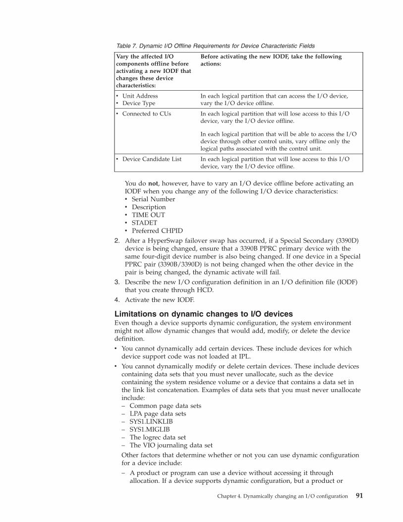
Table 7. Dynamic I/O Offline Requirements for Device Characteristic Fields
Vary the affected I/Ocomponents offline beforeactivating a new IODF thatchanges these devicecharacteristics:
Before activating the new IODF, take the followingactions:
v Unit Addressv Device Type
In each logical partition that can access the I/O device,vary the I/O device offline.
v Connected to CUs In each logical partition that will lose access to this I/Odevice, vary the I/O device offline.
In each logical partition that will be able to access the I/Odevice through other control units, vary offline only thelogical paths associated with the control unit.
v Device Candidate List In each logical partition that will lose access to this I/Odevice, vary the I/O device offline.
You do not, however, have to vary an I/O device offline before activating anIODF when you change any of the following I/O device characteristics:v Serial Numberv Descriptionv TIME OUTv STADETv Preferred CHPID
2. After a HyperSwap failover swap has occurred, if a Special Secondary (3390D)device is being changed, ensure that a 3390B PPRC primary device with thesame four-digit device number is also being changed. If one device in a SpecialPPRC pair (3390B/3390D) is not being changed when the other device in thepair is being changed, the dynamic activate will fail.
3. Describe the new I/O configuration definition in an I/O definition file (IODF)that you create through HCD.
4. Activate the new IODF.
Limitations on dynamic changes to I/O devicesEven though a device supports dynamic configuration, the system environmentmight not allow dynamic changes that would add, modify, or delete the devicedefinition.v You cannot dynamically add certain devices. These include devices for which
device support code was not loaded at IPL.v You cannot dynamically modify or delete certain devices. These include devices
containing data sets that you must never unallocate, such as the devicecontaining the system residence volume or a device that contains a data set inthe link list concatenation. Examples of data sets that you must never unallocateinclude:– Common page data sets– LPA page data sets– SYS1.LINKLIB– SYS1.MIGLIB– The logrec data set– The VIO journaling data setOther factors that determine whether or not you can use dynamic configurationfor a device include:– A product or program can use a device without accessing it through
allocation. If a device supports dynamic configuration, but a product or
Chapter 4. Dynamically changing an I/O configuration 91
program that uses that device does not support dynamic configuration, youmust not define that device as dynamic. See “UCB services considerations” onpage 113.
Note: Do not define devices that contain control volumes (CVOLs) asdynamic devices; define them only as installation-static.
– If you plan to use a pair of devices in a dynamic device reconfiguration(DDR) swap, both devices must have the following two attributes in common:- Whether the device type supports dynamic configuration- Whether the device is defined as dynamic
Any dynamic change that causes a device's UCB to be deleted and added again,causes the device's MIH time interval to be reset to the default MIH setting for itsdevice class. To reestablish the previous MIH interval, enter the SETIOS MIHcommand when the dynamic change is completed. For information about theSETIOS MIH command, see z/OS MVS System Commands.
Console devices: You can define console devices as dynamic; however:v You can dynamically delete or modify any device that was defined as a console
in the CONSOLxx member of SYS1.PARMLIB at IPL only after the consoledefinition has been removed from the system by IEAVG730 or IEARELCN. Forinformation about removing a console through these methods, see z/OS MVSPlanning: Operations .
v You cannot use any dynamically added device as an MCS console.
Considerations for z/OS installed productsCertain products installed with z/OS require that you take additional steps todefine a configuration change to the product. If you do not take these additionalsteps before making a dynamic configuration change, the configuration defined tothese products might be out of synchronization with the z/OS configurationdefinition.
After you dynamically add an I/O device to z/OS, define it to other productsthrough their specific interfaces for defining I/O configurations. For example, toadd a Virtual Telecommunications Access Method (VTAM) device:1. Dynamically add the VTAM device to z/OS.2. Create a new telecommunication program (TP) topology that includes the
VTAM device you are adding.3. Define that new TP topology to VTAM.
When you delete an I/O device definition, first remove the definition from therelated product, then delete the I/O device from z/OS by activating a newconfiguration definition. For example, to delete a VTAM device:1. Create a new TP topology that does not include the device you are deleting.2. Define that new TP topology to VTAM.3. Dynamically delete the VTAM device from z/OS.
Making dynamic changes to channel pathsYou can add, modify, and delete channel path definitions. If you define a device asstatic or installation-static, you cannot delete or modify the channel path definitionto that device.
92 z/OS V1R12.0 HCD Planning
Using an IBM zSeries 900 or later processor, you will be able to dynamically add,delete, or modify coupling facility receiver channels and coupling facility peerchannels. For an S/390 9672 Parallel Transaction Server, you cannot dynamicallyadd, delete, or modify coupling facility receiver (CF receiver) channels. However,at POR, you could define more CF receiver channels than are currently connectedto coupling facility sender channels. Later, to create more connections from anoperating system to the coupling facility, you can activate an IODF thatdynamically adds CF sender channels connected to the defined CF receiverchannels.
Dynamically adding channel pathsTo dynamically add a channel path, use the following general steps:1. Describe the new I/O configuration definition in an I/O definition file (IODF)
that you create through HCD. Including a channel path in an IODF adds thatI/O component's definition to the I/O configuration definition.
2. Activate the new IODF.3. Install the new I/O components that you have dynamically added through the
new IODF. As required, configure the channel paths.
Dynamically deleting channel pathsHow you dynamically delete a channel path depends on whether or not thatchannel path shares any control units and devices with one or more other channelpaths.
To delete a channel path that is the only channel path attached to all of its devicesand control units, use the following steps:1. Describe the new I/O configuration definition in an I/O definition file (IODF)
that you create through HCD. Create an IODF that defines neither the channelpath nor its devices and control units.
2. Ensure that the channel path and its devices and control units are not in use byany application.
3. Vary all I/O devices on the channel path offline to z/OS.4. Configure the channel path offline to z/OS.5. Physically remove the channel path and all I/O devices and control units on
the channel path.6. Activate the new IODF.
To delete a channel path that is not the only channel path attached to its devicesand control units, use the following general steps:1. Describe the new I/O configuration definition in an I/O definition file (IODF)
that you create through HCD. Create an IODF that meets both of the followingrequirements:v The new IODF does not define the channel path or the devices and control
units attached exclusively on the channel path.v The new IODF does define those device and control units also attached on
other channel paths.2. Ensure that no devices and control units on this channel path are in use by this
channel path.3. For all devices not exclusively on this channel path, vary offline to z/OS all
device paths through this channel path.4. Vary offline to z/OS all devices exclusively on this channel path.5. Configure the channel path offline to z/OS.
Chapter 4. Dynamically changing an I/O configuration 93

6. Physically remove the channel path and the I/O devices and control unitsexclusively on this channel path.
7. Activate the new IODF.
There is a consideration when you delete CF sender channel paths. If a couplingfacility is defined in the coupling facility resource management (CFRM) policy andhas working connections from a z/OS system to the coupling facility, you cannotmake dynamic changes that cause a loss of connectivity to the facility. For example,you cannot dynamically delete the last operational coupling facility channel path.
To delete the last channel path connected to the coupling facility, use the followinggeneral steps:1. If the coupling facility is in the current CFRM policy, activate a new policy that
does not specify the coupling facility. For information about setting up andactivating the CFRM policy, see z/OS MVS Setting Up a Sysplex.
2. Configure the channel path offline to z/OS.3. Physically remove the channel path.4. Activate a new IODF.
Dynamically changing channel pathsTo dynamically change a channel path, use the following general steps:1. For channel paths that you plan to change, if you are changing certain fields in
the IODF, you must configure channel paths offline.To guard against losing I/O access unexpectedly, you must vary offline I/Odevices before you activate an IODF that changes the characteristic fieldsdescribed in Table 8:
Table 8. Dynamic I/O Offline Requirements for Channel Path Fields
Vary the affectedcomponents offline beforeactivating a new IODF thatchanges these channel pathcharacteristics:
Before activating the new IODF, take the followingactions:
v Channel Path Typev Dynamic Switch IDv Operation Mode
In all logical partitions in your processor complex,configure the channel path offline. If the channel path is thelast path to an I/O device, you must vary the device offlinebefore you can configure the channel path offline.
v Channel Path Access Listv Channel Path Candidate
List
In each logical partition that will lose access to I/O deviceson this channel path, do the following:
1. For I/O devices that will become inaccessible to thelogical partition, vary those I/O devices offline.
2. For I/O devices that will remain accessible by thelogical partition through other channel paths, varyoffline only the logical paths associated with thischannel path.
3. Configure the channel path offline.Note: For coupling facility sender channel paths, youmust first vary the CF sender channel path offline to thecoupling facility.
In all logical partitions that will gain access or continueaccessing this channel path, you need not configure or varyanything offline.
94 z/OS V1R12.0 HCD Planning
Note: This table is also valid for spanned channels.You do not, however, have to vary an I/O device offline before activating anIODF when you change any of the following I/O device characteristics:v Entry Switch Numberv Entry Portv Description
2. Describe the new I/O configuration definition in an I/O definition file (IODF)that you create through HCD.
3. Activate the new IODF.
Note: You usually cannot remove a logical partition from a channel pathcandidate list unless the channel path is offline. You can, however,remove a logical partition, other than your own, from the channel pathcandidate list for a reconfigurable or shared ESCON connection (CNCand CTC) or coupling facility sender channel path while the channelpath is online to the other logical partition if you perform one of thefollowing actions:
v Use the ACTIVATE command with the FORCE(CANDIDATE) parameter.v On the HCD Activate New Hardware and Software Configuration panel,
specify “Yes” in the “Delete partition access to CHPIDs unconditionally(FORCE=CANDIDATE)” field.
Making dynamic changes to control unitsYou can add, modify, and delete control unit definitions.
Dynamically adding control unitsTo dynamically add a control unit, use the following general steps:1. Describe the new I/O configuration definition in an I/O definition file (IODF)
that you create through HCD. Including an I/O component in an IODF addsthat I/O component's definition to the I/O configuration definition.
2. Activate the new IODF.3. Install the new I/O components that you have dynamically added through the
new IODF. As required, configure the channel paths, format the I/O devices,and vary the I/O components online.
Dynamically deleting control unitsz/OS verifies that the control units are not in use (that the set of all device pathsare offline) before deleting the control unit.
How you dynamically delete a control unit depends on whether or not that controlunit shares any devices with one or more other control units.
To delete a control unit that is the only control unit attached to all its devices, usethe following general steps:1. Describe the new I/O configuration definition in an I/O definition file (IODF)
that you create through HCD. Create an IODF that defines neither the controlunit nor its attached devices.
2. Ensure that none of the devices on the control unit are in use by anyapplication.
3. Vary all devices on the control unit offline to z/OS.4. Physically remove the control unit and all its attached devices.5. Activate the new IODF.
Chapter 4. Dynamically changing an I/O configuration 95
|
To delete a control unit attached to any devices that are also attached to one ormore other control units, use the following general steps:1. Describe the new I/O configuration definition in an I/O definition file (IODF)
that you create through HCD. Create an IODF that meets both of the followingrequirements:v The new IODF does not define the control unit or its exclusively attached
devices.v The new IODF does define those devices also attached to other control units.
2. Ensure that none of the devices exclusively on this control unit are in use byany application.
3. Vary offline to z/OS all devices exclusively on the control unit. For all devicesalso attached to other control units, vary offline to z/OS all device pathsthrough this control unit.
4. Physically remove the control unit and all its exclusively attached devices.5. Activate the new IODF.
Dynamically changing control unitsTo dynamically change a control unit, use the following general steps:1. For control units that you plan to change, if you are changing particular fields
in the IODF, you must vary attached devices offline.To guard against losing I/O access unexpectedly, you must vary offline I/Odevices before you activate an IODF that changes the characteristic fieldsdescribed in Table 9:
Table 9. Dynamic I/O Offline Requirements for Control Unit Fields
Vary the affected I/Ocomponents offline beforeactivating a new IODF thatchanges these control unitcharacteristics:
Before activating the new IODF, take the followingactions:
v Control unit attachmenttype
v Logical Addressv Protocolv I/O Concurrency Level
v Vary offline all I/O devices connected to the control unit.This is required when the attachment type changes, forexample, from ESCON to FICON or from serial toparallel.
v Channel Path IDsv Link Address
In each logical partition that will lose access to I/O deviceson this control unit, do the following:
1. For I/O devices that will become inaccessible to thelogical partition, vary those I/O devices offline.
2. For I/O devices that will remain accessible by thelogical partition through other channel paths, varyoffline only the logical paths that you are removingfrom this control unit.
v Unit Addresses (withRanges and Numbers ofUnits)
Before deleting a unit address, vary its associated I/Odevice offline.
You do not, however, have to vary an I/O device offline before activating anIODF when you change any of the following control unit characteristics:v Serial Numberv Description
2. Describe the new I/O configuration definition in an I/O definition file (IODF)that you create through HCD.
3. Activate the new IODF.
96 z/OS V1R12.0 HCD Planning
|||||
|

Making changes to coupling facility devices and control unitsCoupling facility devices and control units are defined to represent the connectionsin the channel subsystem connection to a coupling facility. The coupling facilitycontrol unit and device definitions are created in an IODF when you connect CFsender and CF receiver channel paths or two CF peer channel paths using HCD.One coupling facility control unit and two coupling facility devices are definedwhen you first connect a CF sender channel path to a CF receiver channel path fora coupling facility. Each subsequent channel connection adds two more couplingfacility device definitions. For a CF peer channel connection, one control unit andseven CF device definitions are generated on one or on both sides of theconnection depending on whether the sending function is used on only one or onboth sides of the connection. You do not explicitly add or delete coupling facilitydevices and control units in the IODF; they are added and deleted based on the CFsender-to-receiver or peer-to-peer channel connections that you make.
To use the coupling facility after you make the connections, a CFRM policycontaining the coupling facility must be active. For information about setting upand activating a CFRM policy, see z/OS MVS Setting Up a Sysplex.
A CF sender-to-CF receiver or peer-to-peer connection can cause changes to acoupling facility control unit definition. The first path you connect adds thecoupling facility control unit and the last path you disconnect deletes the couplingfacility control unit, but all other connections and disconnections of channel pathschange the control unit definition.
The following sections describe how dynamic changes are made to couplingfacility devices and control units when you connect and disconnect channel pathsfor a processor.
Making the first channel path connection for a coupling facilityWhen you connect the first CF sender channel path to a CF receiver channel pathfor a coupling facility, HCD creates a coupling facility control unit and twocoupling facility device definitions in an IODF. When you connect the first two CFpeer channel paths for a coupling facility, HCD creates a coupling facility controlunit and seven coupling facility device definitions in an IODF.
Perform the following steps when you connect the first CF sender channel path orCF peer channel path:1. In HCD, connect a CF sender channel path to a CF receiver channel path, or
connect two CF peer channel paths.2. Accept or change the control unit and device numbers HCD proposes.3. Activate the new IODF.4. Install the channel path.5. To allow the system to use the coupling facility, activate a coupling facility
resource management (CFRM) policy that defines the coupling facility, if one isnot already activated.
6. Configure the channel path online.
Making subsequent channel path connections for a couplingfacilityWhen you make subsequent CF sender-to-CF receiver channel path connections fora coupling facility, HCD creates two coupling facility device definitions in theIODF. When you make subsequent CF peer-to-peer channel path connections for acoupling facility, HCD creates seven coupling facility device definitions in the
Chapter 4. Dynamically changing an I/O configuration 97

IODF. For both the CF sender channel path connection and the CF peer channelpath connection, HCD also changes the existing coupling facility control unitdefinition to reflect the new channel path connection in the IODF.
Perform the following steps when you connect subsequent CF sender or CF peerchannel paths:1. In HCD, connect a CF sender channel path to a CF receiver channel path, or
connect two CF peer channel paths.2. Accept or change the device numbers proposed by HCD.3. Activate the new IODF.4. Install the channel path.5. Configure the channel path online.
Breaking a channel path connection that is not the lastconnection to a coupling facilityWhen you disconnect a CF sender channel path connection that is not the lastconnection for a coupling facility, HCD deletes two coupling facility devicedefinitions in the IODF. When you disconnect a CF peer channel path connectionthat is not the last connection for a coupling facility, HCD deletes seven couplingfacility device definitions in the IODF. For both the CF sender channel pathdisconnection and the CF peer channel path disconnection, HCD also changes theexisting coupling facility control unit definition to reflect the channel pathdisconnection in the IODF.
Perform the following steps when you disconnect a CF sender or a CF peerchannel path that is not the last channel path connection to the coupling facility:1. Disconnect a CF channel path from the CF receiver channel path, or disconnect
the two CF peer channel paths.2. Configure the disconnected channel path offline.3. Activate the new IODF.
Breaking the last channel path connection to a coupling facilityWhen you disconnect the last CF sender channel path connection for a couplingfacility, HCD deletes a coupling facility control unit and two coupling facilitydevice definitions in the IODF. When you disconnect the last CF peer channel pathconnection for a coupling facility, HCD deletes a coupling facility control unit andseven coupling facility device definitions in the IODF.
Note: If a coupling facility is defined in the active coupling facility resourcemanagement (CFRM) policy, you cannot dynamically delete the couplingfacility control unit by disconnecting the last channel paths.
Perform the following steps when you disconnect the last CF sender channel pathor the last CF peer channel path from a coupling facility:1. Quiesce activity to the coupling facility by activating a CFRM policy that does
not contain the coupling facility.2. Disconnect the last CF sender or CF peer channel path from a processor to a
coupling facility in the IODF definition.3. Activate the new IODF.
98 z/OS V1R12.0 HCD Planning
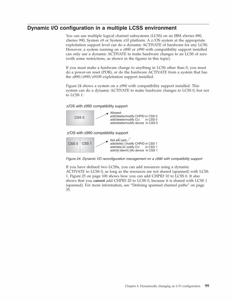
Dynamic I/O configuration in a multiple LCSS environmentYou can use multiple logical channel subsystems (LCSS) on an IBM zSeries 890,zSeries 990, System z9 or System z10 platform. A z/OS system at the appropriateexploitation support level can do a dynamic ACTIVATE of hardware for any LCSS.However, a system running on a z890 or z990 with compatibility support installedcan only use a dynamic ACTIVATE to make hardware changes to an LCSS of zero(with some restrictions, as shown in the figures in this topic).
If you must make a hardware change to anything in LCSS other than 0, you mustdo a power-on reset (POR), or do the hardware ACTIVATE from a system that hasthe z890/z990/z9109 exploitation support installed.
Figure 24 shows a system on a z990 with compatibility support installed. Thissystem can do a dynamic ACTIVATE to make hardware changes to LCSS 0, but notto LCSS 1:
If you have defined two LCSSs, you can add resources using a dynamicACTIVATE to LCSS 0, as long as the resources are not shared (spanned) with LCSS1. Figure 25 on page 100 shows how you can add CHPID 10 to LCSS 0. It alsoshows that you cannot add CHPID 20 to LCSS 0, because it is shared with LCSS 1(spanned). For more information, see “Defining spanned channel paths” on page35.
z/OS with z990 compatibility support
CSS 0
Allowed:add/delete/modify CHPID in CSS 0add/delete/modify CU in CSS 0add/delete/modifu device in CSS 0
z/OS with z990 compatibility support
Not allowed:add/delete/modify CHPID in CSS 1add/delete/modify CU in CSS 1add/delete/modifu device in CSS 1
CSS 0 CSS 1 XFigure 24. Dynamic I/O reconfiguration management on a z990 with compatibility support
Chapter 4. Dynamically changing an I/O configuration 99
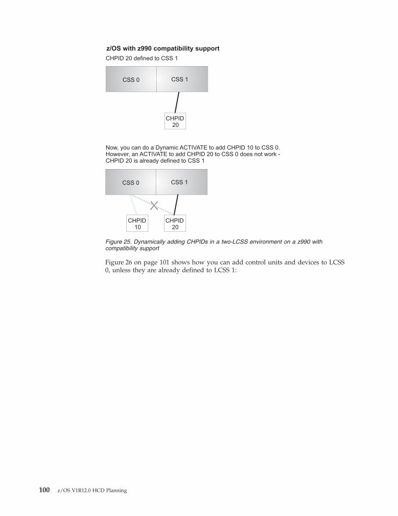
Figure 26 on page 101 shows how you can add control units and devices to LCSS0, unless they are already defined to LCSS 1:
CSS 0 CSS 1
CHPID20
CSS 0 CSS 1
CHPID10
CHPID20
X
Now, you can do a Dynamic ACTIVATE to add CHPID 10 to CSS 0.However, an ACTIVATE to add CHPID 20 to CSS 0 does not work -CHPID 20 is already defined to CSS 1
CHPID 20 defined to CSS 1
z/OS with z990 compatibility support
Figure 25. Dynamically adding CHPIDs in a two-LCSS environment on a z990 withcompatibility support
100 z/OS V1R12.0 HCD Planning
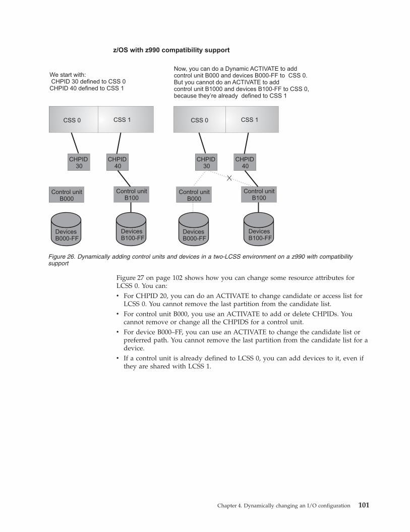
Figure 27 on page 102 shows how you can change some resource attributes forLCSS 0. You can:v For CHPID 20, you can do an ACTIVATE to change candidate or access list for
LCSS 0. You cannot remove the last partition from the candidate list.v For control unit B000, you use an ACTIVATE to add or delete CHPIDs. You
cannot remove or change all the CHPIDS for a control unit.v For device B000–FF, you can use an ACTIVATE to change the candidate list or
preferred path. You cannot remove the last partition from the candidate list for adevice.
v If a control unit is already defined to LCSS 0, you can add devices to it, even ifthey are shared with LCSS 1.
CSS 0 CSS 1
CHPID30
CHPID40
Control unitB000
DevicesB000-FF
Control unitB100
DevicesB100-FF
X
CSS 0 CSS 1
CHPID30
CHPID40
Control unitB000
DevicesB000-FF
Control unitB100
DevicesB100-FF
We start with:CHPID 30 defined to CSS 0CHPID 40 defined to CSS 1
Now, you can do a Dynamic ACTIVATE to addcontrol unit B000 and devices B000-FF to CSS 0.But you cannot do an ACTIVATE to addcontrol unit B1000 and devices B100-FF to CSS 0,because they’re already defined to CSS 1
z/OS with z990 compatibility support
Figure 26. Dynamically adding control units and devices in a two-LCSS environment on a z990 with compatibilitysupport
Chapter 4. Dynamically changing an I/O configuration 101
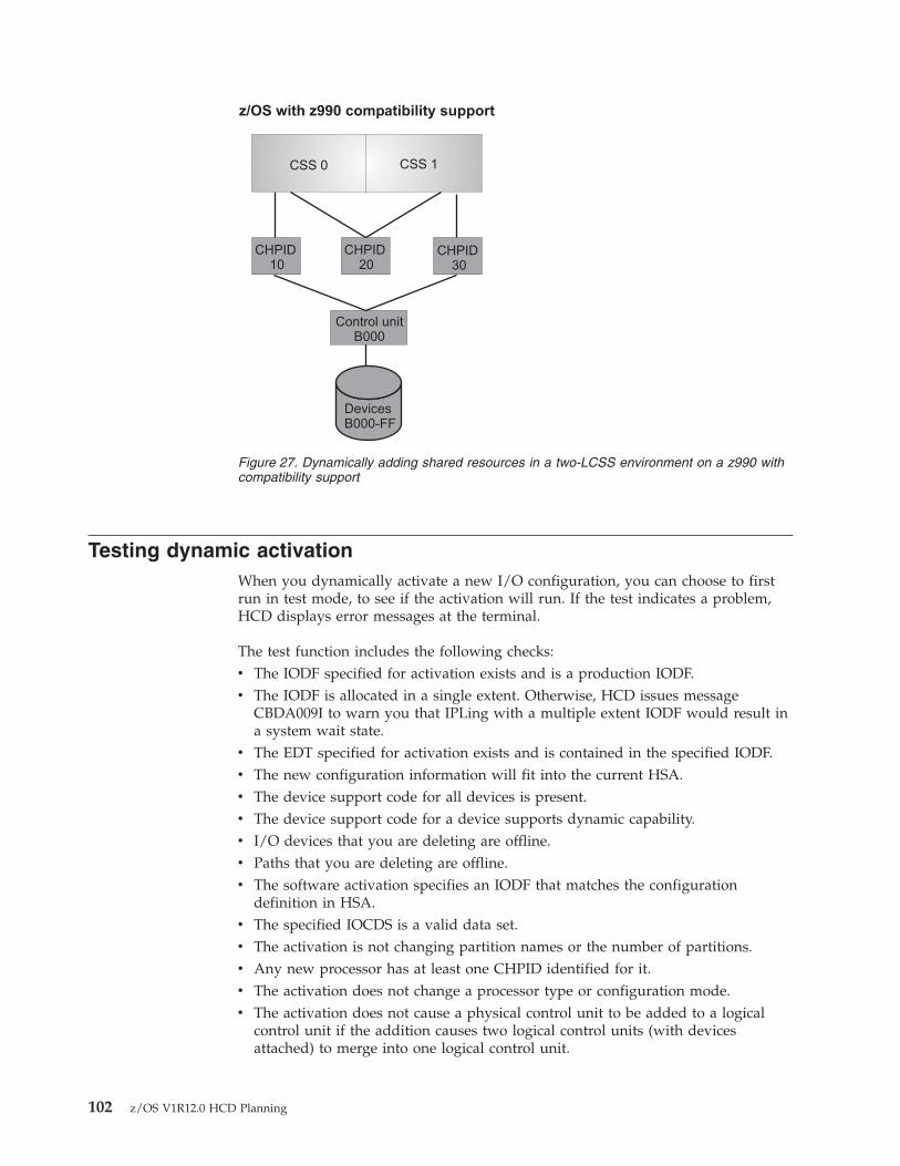
Testing dynamic activationWhen you dynamically activate a new I/O configuration, you can choose to firstrun in test mode, to see if the activation will run. If the test indicates a problem,HCD displays error messages at the terminal.
The test function includes the following checks:v The IODF specified for activation exists and is a production IODF.v The IODF is allocated in a single extent. Otherwise, HCD issues message
CBDA009I to warn you that IPLing with a multiple extent IODF would result ina system wait state.
v The EDT specified for activation exists and is contained in the specified IODF.v The new configuration information will fit into the current HSA.v The device support code for all devices is present.v The device support code for a device supports dynamic capability.v I/O devices that you are deleting are offline.v Paths that you are deleting are offline.v The software activation specifies an IODF that matches the configuration
definition in HSA.v The specified IOCDS is a valid data set.v The activation is not changing partition names or the number of partitions.v Any new processor has at least one CHPID identified for it.v The activation does not change a processor type or configuration mode.v The activation does not cause a physical control unit to be added to a logical
control unit if the addition causes two logical control units (with devicesattached) to merge into one logical control unit.
CSS 0 CSS 1
CHPID10
CHPID20
CHPID30
Control unitB000
DevicesB000-FF
z/OS with z990 compatibility support
Figure 27. Dynamically adding shared resources in a two-LCSS environment on a z990 withcompatibility support
102 z/OS V1R12.0 HCD Planning
v The activation does not cause a physical control unit to be removed from alogical control unit if the deletion causes a split of one logical control unit (withdevices attached) into two logical control units.
v The activation does not change a coupling facility receiver channel path.v The activation does not cause a loss of connectivity to an active coupling facility
by deleting the last operational channel path from the coupling facility controlunit.
You can run with the test function before you activate using the HCD panels orACTIVATE command. On the HCD Activate New Configuration panels, there is aTEST Only field in which you can specify YES to test the activation and NO towhen you ready to perform the activation. To use the test function with theACTIVATE command, specify the TEST keyword. Omit the TEST keyword toactually perform the activation.
There are some checks that the test function does not perform that the actualactivation does:v The test function does not check for pinned devices because devices are only
unpinned for the actual delete signal. This is more efficient. It is also possiblethat during a test the device would not be pinned and then attention processingcauses the device to be pinned during actual activate.
v The test function also does not check SQA storage requirements for changes dueto activate on the test.
If you activate hardware and software in test mode, HCD can provide informationabout channel paths, control units, and devices that are deleted, modified, oradded. To obtain this information, you must either:v Set the HCD profile option SHOW_IO_CHANGES=YES in the HCD dialog, orv Enter the ACTIVATE command using the activate action in the HCD dialog.
Recovery during dynamic configurationIf your system fails while making dynamic configuration changes to the hardwaredefinition, you can recover the I/O configuration even if the system failurerequires a reIPL.
Notes:
1. Although these recovery procedures describe using the ACTIVATE command,you can also use an HCD panel to recover from a failure that occurs duringdynamic configuration changes. When HCD recommends recovery duringconfiguration activation, a panel displays where you can specify recoveryoptions. You can choose to try to continue with the activation or to reset theconfiguration to the original (source) configuration. For more information, seez/OS HCD User's Guide.
2. If your processor is running in logically partitioned (LPAR) mode, see“Recovering LPAR mode dynamic configuration changes” on page 104.
Recovering dynamic configuration changesAfter a failure during a dynamic configuration change, you can either recover theconfiguration that was active before the failure or continue making changes fromthe point of failure and complete the configuration change. In the latter case, z/OSmust have access to both the source IODF, which defines the original I/Ohardware configuration, and the target IODF, which defines the new I/O hardwareconfiguration.
Chapter 4. Dynamically changing an I/O configuration 103
Recovering original I/O configuration without reIPLIf the system failure does not require a reIPL, and you want to recover the I/Oconfiguration that was active before the failure, enter the ACTIVATE commandwith the RECOVER keyword and SOURCE option. z/OS backs out all dynamicI/O hardware changes made prior to the failure, returning the system to itsoriginal (source) I/O hardware configuration.
Continuing I/O configuration changes without reIPLIf the failure does not require a reIPL, and you want to continue making dynamicconfiguration changes from the point of failure, enter the ACTIVATE commandwith the RECOVER keyword and TARGET option. z/OS continues making theremaining dynamic configuration changes, finishing building the new (target) I/Ohardware configuration. If you do not specify TARGET or SOURCE option, z/OScontinues in the same direction as when failure occurred.
Recovering original I/O configuration with reIPLIf the system failure requires a reIPL, and you want to recover the I/Oconfiguration that was active before the failure, follow these steps:1. Specify the source IODF in the LOADxx member of SYS1.PARMLIB or
SYSn.IPLPARM. For more information, see “IODF processing at IPL” on page76.
2. ReIPL the system.3. Enter the ACTIVATE command with the RECOVER keyword and SOURCE
option. z/OS backs out all dynamic hardware changes made prior to thefailure, returning the system to its original (source) I/O hardwareconfiguration.
Continuing I/O configuration changes with reIPLIf the failure requires a reIPL, and you want to continue making dynamicconfiguration changes from the point of failure, follow these steps:1. Specify the target IODF in the LOADxx member of SYS1.PARMLIB or
SYSn.IPLPARM. For more information, see “IODF processing at IPL” on page76.
2. ReIPL the system.3. Enter the ACTIVATE command with the RECOVER keyword and TARGET
option. z/OS continues making the remaining dynamic changes, finishingbuilding the new (target) I/O hardware configuration.
Recovering LPAR mode dynamic configuration changesIn LPAR mode, after a failure during a dynamic configuration change, you canrecover the system to its original I/O configuration or continue making dynamicconfiguration changes from either the logical partition that had failed or from anyother logical partition.
Recovering original LPAR mode I/O configuration without systemresetIf your processor was running in LPAR mode, the failure does not require a systemreset, and you want to recover the I/O configuration that was active before thefailure occurred, follow these steps:1. In all logical partitions, to make software-only changes, activate the source
IODF.2. In any logical partition, enter the ACTIVATE command with the RECOVER
keyword and SOURCE option. z/OS backs out all dynamic configuration
104 z/OS V1R12.0 HCD Planning
changes made prior to the failure, returning the system to its original (source)I/O hardware configuration, which is shared by all logical partitions.
Continuing LPAR mode I/O configuration changes withoutsystem resetIf your processor was running in LPAR mode, the failure does not require a systemreset, and you want to continue making dynamic configuration changes from thepoint of failure, do the following:v In any logical partition, enter the ACTIVATE command with the RECOVER
keyword and TARGET option. z/OS continues making the remaining dynamicconfiguration changes, finishing building the new (target) I/O hardwareconfiguration, which is shared by all logical partitions.
Recovering original LPAR mode I/O configuration with systemresetIf your processor was running in LPAR mode, the failure requires a system reset,and you want to recover the I/O configuration that was active before the failureoccurred, follow these steps:1. In the logical partition that failed, specify the source IODF in the LOADxx
member of SYS1.PARMLIB or SYSn.IPLPARM. For more information, see“IODF processing at IPL” on page 76.
2. For Enterprise System/9000, perform system reset on the logical partition thatfailed. For more information, see Enterprise System/9000 Operator Guide.
3. In all logical partitions, make software-only changes, activating the sourceIODF.
4. In any logical partition, enter the ACTIVATE command with the RECOVERkeyword and SOURCE option. z/OS backs out all dynamic configurationchanges made prior to the failure, returning the system to its original (source)I/O hardware configuration, which is shared by all logical partitions.
Continuing LPAR mode I/O configuration changes with systemresetIf your processor was running in LPAR mode, the failure requires a system reset,and you want to continue making dynamic configuration changes from the pointof failure, follow these steps:1. In the logical partition that failed, specify the target IODF in the LOADxx
member of SYS1.PARMLIB or SYSn.IPLPARM. For more information, see“IODF processing at IPL” on page 76.
2. Perform system reset on the logical partition that failed. For more information,see Enterprise System/9000 Operator Guide .
3. In any logical partition, enter the ACTIVATE command with the RECOVERkeyword and TARGET option. This continues making the remaining dynamicconfiguration changes, finishing building the new (target) I/O hardwareconfiguration, which is shared by all logical partitions.
Chapter 4. Dynamically changing an I/O configuration 105

106 z/OS V1R12.0 HCD Planning
Using HCM to migrate to IBM zSeries z890 or z990
With z/OS V1R4 and z/VM V4R4, a new FMID HCM1510 is provided for HCM. Ifyou have installed this FMID or a later version of HCM, then HCM can handle theIBM zSeries 990 (z990) and the IBM zSeries 890 (z890). You must also have FMIDHCS7708 for HCD installed - HCM needs this FMID to provide support for thenew server.
With z/OS V1R7, all toleration PTFs must be installed before HCM can use thez9109 platform.
This topic describes scenarios how to migrate from an I/O configuration attachedto a pre-z990 processor to a z990 or z890 processor using HCM. If you are usingHCD to migrate to z990 or z890 processors, use z/OS HCD User's Guide.
The major difference between the new z9109, z990 and z890 processors and theirpredecessors is that the new processor definitions contain logical channelsubsystems. Therefore, a new object has been introduced into the hierarchy for aprocessor definition:
Processors —> Channel subsystems —> Partitions —> Channel paths
With this new hierarchy you cannot simply edit the processor type/modelinformation within the HCM or HCD dialog, but you need to perform a series ofmigration steps using HCM and HCD. These steps are described in the following.
This topic discusses the following alternatives:v “Configurations with logical definitions only”v “Configurations including physical definitions” on page 108
Note:Before you start the migration steps, we recommend that you first read thetopic on importing and exporting data in z/OS and z/VM HCM User's Guide.This topic describes the steps for exporting or importing data, and alsoexplains what information you can update when importing files.
Configurations with logical definitions onlyIf you use HCM for your configuration definitions without documenting yourphysical environment, then migrating from a pre-z990 processor to a z990 or z890processor is a straightforward task. Perform the following steps in the given order:1. Create backup copies of your HCM configuration file and of your IODF.2. Create a new z990 or z890 processor using HCM, and define the required
number of logical channel subsystems.3. Exit HCM, and continue to work on the IODF using HCD:
v Navigate to the Processor List:a. Look for the pre-z990 processor with the I/O configuration that you want
to migrate. The basic migration task is to copy the I/O configuration ofthe pre-z990 processor into a logical channel subsystem on the new
© Copyright IBM Corp. 1989, 2010 107
processor. Therefore, on your source processor, apply action Copy tochannel subsystem. . . (SMP) from the context menu (or action code �y�).
b. Specify the IODF to which the selected operating system is to be copied.The default IODF is the IODF you are currently working with.
c. Specify the target processor ID and select the logical channel subsystemID as requested. Pressing the Enter key copies the source processor I/Odefinition into the logical channel subsystem of the target processor. Notethat coupling facility connections are not copied.
v Delete the source processor definition that you copied into the logicalchannel subsystem.
v Establish the coupling facility connections between the CF CHPIDs on otherprocessors and the CHPIDs in the logical channel subsystem into which youcopied the processor definition. Also establish the CF connections within thez990/z890 processor (if needed). Note that you first might need to set the CFCHPIDs in the target logical channel subsystem to 'not occupied'.
v Perform the PCHID migration for the CHPIDs on the new z990 processorusing HCD and the CHPID Mapping Tool as described in the z/OS HCDUser's Guide.
4. Exit HCD and return to HCM. Reload the HCM configuration file. HCM willnow force a resynchronization with the IODF. Check whether your CTCconnections from and to the logical channel subsystem are as expected. Youneed not check CTC connections between processors not involved in themigration.HCM detects and establishes all new switched CTC connections, but does notrecognize point-to-point CTC connections. Establish these point-to-point CTCconnections using the Create CTC Connections dialog. You need not type theCTC control units and CTC devices into the dialog, because HCM detects thatthe selected CHPIDs are already connected to CTC control units and CTCdevices. Simply accept HCM's proposed CTC control units and CTC devices,and the point-to-point CTC connections will also be documented in HCM.Note that the CTC connections themselves were already logically defined in theIODF, but HCM has now also documented their physical configuration.
5. The migration process is now complete. The pre-z990 processor I/Oconfiguration has been successfully copied into a z990/z890 processor's logicalchannel subsystem definition.
Configurations including physical definitionsIf you use HCM to document both your logical and physical environment, then themigration task consists of a few more steps. Perform the following steps withoutchanging the order:1. Create backup copies of your HCM configuration file and of your IODF.2. Generic Converters: If there are any connections defined between CHPIDs of
the source processor definition and other objects where a converter isinvolved, then make sure that the converter is not a 'generic' converter thatwas automatically created by HCM. Double click on the converter object, andpress the Replace button. On the following Replace Converter dialog, create aconverter with label and serial number — you now have your own converterin the connection. If you keep generic converters, you will receive errormessages during the later migration steps. If you do not want to create yourown converters, but want to keep generic converters only, then you need todisconnect all connections to the processor that is being migrated whereconverters are involved in the link. Remember to reconnect them at the end ofthe whole procedure.
108 z/OS V1R12.0 HCD Planning
3. Save the HCM configuration file, and export the HCM files 'CONNECT.txt'and 'LOGLINK.txt'.You might receive some error messages during the export step. If you receiveerror message’EEQ0261E: CCI<controller interface> is not unique,so it has not been exported’
then check whether the mentioned interface is directly connected to a CHPIDof the source processor. If so, make sure that the controller interface is uniquein your configuration. Most likely, you have created your own PDF file andlabeled different interfaces with the same name. Make sure that yourinterfaces are uniquely labeled in the PDF files.In case you receive message ’EEQ0261E: CCI ...’ or ’EEQ0261E: CDI ...’,check whether one of your PDF files is set up in a way that two or moreinterfaces have the same label. If this is the case, copy and modify the PDFfile to use unique labels for all interfaces. For the modified PDF file, use adifferent file name (to preserve the original PDF file if needed), and provide anew subsystem identifier within the modified PDF file. After you modified thePDF file, you need to change the physical description for all controllers whereyou used the original PDF file, and you now need to apply the new PDF file.You can do so by clicking on the Edit Controller dialog where you then canselect your modified PDF file.In contrast to normal processing, HCM cannot handle duplicate objects likeinterface names as soon as data gets exported. So it is important that all yourobjects and all your interfaces are uniquely labeled.
4. Create a new z990/z890 processor using HCM, and define the requirednumber of logical channel subsystems.
5. Exit HCM, and continue to work on the IODF using HCD:v Navigate to the Processor List:
a. Look for the pre-z990 processor with the I/O configuration that youwant to migrate. The basic migration task is to copy the I/Oconfiguration of the pre-z990 processor into a logical channel subsystemof the new processor. Therefore, on your source processor, you applyaction Copy to channel subsystem. . . (SMP) from the context menu (oraction code �y�).
b. Specify the IODF to which the selected operating system is to be copied.The default IODF is the IODF you are currently working with.
c. Specify the target processor ID and select the logical channel subsystemID. Pressing the Enter key copies the source processor I/O definitioninto the logical channel subsystem of the target processor. Note thatcoupling facility connections are not copied.
v Delete the source processor definition that you copied into the logicalchannel subsystem.
v Establish the coupling facility connections between the CF CHPIDs on otherprocessors and the CHPIDs in the logical channel subsystem, and alsoestablish the CF connections within the z990/z890 processor (if needed).Note that you first might need to set the CF CHPIDs in the target logicalchannel subsystem to 'not occupied'.
v Perform the PCHID migration for the CHPIDs on the new z990 processorusing HCD and the CHPID Mapping Tool as described in the z/OS HCDUser's Guide.
6. Exit HCD and return to HCM.7. Use a text editor on your PC to edit the two files that were exported in step 3.
In 'LOGLINK.txt' and 'CONNECT.txt', globally edit every occurrence of theold processor name. Change the old name to the new z990 processor name
Using HCM to migrate to IBM zSeries z890 or z990 109
followed by a dot (.) and the logical channel subsystem ID. For example:exchange 'PROC2064' with 'PROC2084.1' if you have copied a processornamed PROC2064 into logical channel subsystem 1 of processor PROC2084.However, before you globally replace the old processor name, make sure thatthere are no other occurrences of the processor name, for example in a stringlabel or a patchport label.
8. Use HCM and log on to the host again. Do not load the HCM configurationfile, but instead, execute the Import data... action from the File menu. Thisallows you to import the modified files into your HCM configuration file thatyou want to update. During the import step, HCM asks you whether youwant to use the same IODF that is already associated with the HCMconfiguration file. Answer YES to select that option. HCM now performs abackground resynchronization step while importing the data. During theimport step, you may receive several HCM error messages:v Error message EEQ0251I may appear saying "Record not processed. The
configuration contains more than one PATCHPRT object which matches'xxxxxx'.". This indicates that you have patchports in your configurationwith patchport labels that have been manually entered and are identical tothose of other patchports. You can avoid such messages by specifyingpatchport labels that are unique across the whole configuration and are notdefault labels generated by HCM for other patchports.
v Error message EEQ0251I may appear saying "Record not processed. ASTRING object with the identifier 'String #n' does not exist.". String objectsare never directly connected to CHPIDs, so you need not expect problemsfrom this point of view. The record was not processed as reported, so thecurrent physical environment was not changed.
v Error message EEQ0251I may appear saying for example: "Record notprocessed. A CONTRLLR object with the identifier 'Controller forPROC2084.1' does not exist.". In this example, we are migrating fromprocessor PROC2064 to logical channel subsystem 1 of processor PROC2084.If the original label of the controller was 'Controller for PROC2064', and ifyou performed a global change of the processor name even though theprocessor name 'PROC2064' is part of at least one label of another object,then this error message occurs. This error message may also involve furthererror messages as a consequence. Check whether in step 7 on page 109 youperformed an unintentional name change in files 'LOGLINK.txt' and'CONNECT.txt'.
v Warning message EEQ0253I may appear saying that an object has beendisconnected from a CHPID of the deleted processor definition. These aredisconnect requests for HCM physical connections only; no IODF update isinvolved with this disconnect request. Note that the I/O configurationbelow the deleted CHPID remains persistent for the new CHPID on thelogical channel subsystem. For example, if the deleted CHPID wasconnected to patchport 1, which in return was connected to patchport 2,and patchport 2 was finally connected to a switch port, then bothpatchports will be part of the fiber link configuration between the switchport and the new CHPID on the logical channel subsystem. Additionally,the cables involved in this link also remain in their original position.
v HCM does not write certain links into the exported file 'CONNECT.txt'. Themissing connections relate only to daisy-chained controller connectionswhere the first controller interface is further connected via a converter.When you perform the import step 8, HCM detects that a link is missing. Inthis case, you will receive several EEQ0251E error messages saying thatrecords have not been processed followed by one of these messages:– This connection requires another CONNECT record that references the
bottom of converter "MyConverter".
110 z/OS V1R12.0 HCD Planning
– This connection cannot be made because "3480 #1.A.out" is notconnected.
– This connection cannot be made because the connection in fileC:\...\CONNECT.txt at line #000011 could not be made.
– 'MyConverter' is not a valid LOGLINK Target.A fix is being developed and will be made available via a new service level.Check the HCD/HCM home page to find out when this HCM service levelis available.A circumvention for this problem is to disconnect the connection betweenthe first controller interface of the daisy-chained controller interfaces fromthe logical target (the logical target is not the converter because theconverter is just inserted in the link for reasons of documenting the physicalconfiguration). Because the critical link is no longer in the configuration,you could now go on as if you had disconnected all connections whereconverters were involved. See step 2 on page 108.
9. After the import/resynchronization step, you need to check whether yourCTC connections from and to the logical channel subsystem are as expected.You need not check CTC connections between processors that are not involvedin the migration.HCM has detected all new switched CTC connections, but cannot recognizepoint-to-point CTC connections. Establish those point-to-point CTCconnections via the Create CTC Connections dialog. You need not type theCTC control units and CTC devices into the dialog, because HCM detects thatthe selected CHPIDs are already connected to CTC control units and CTCdevices. Simply accept HCM's proposed CTC control units and CTC devices,and the point-to-point CTC connections will also be documented in HCM.Note that the CTC connections themselves were already logically defined inthe IODF, but HCM has now also documented their physical configuration.
10. The migration process is now complete. The pre-z990 processor I/Oconfiguration has been successfully copied into a z990/z890 processor's logicalchannel subsystem definition.
Using HCM to migrate to IBM zSeries z890 or z990 111

112 z/OS V1R12.0 HCD Planning
Migrating to the dynamic capability provided with HCD
For installations that use MVS configuration program (MVSCP), this sectiondescribes how to migrate to the dynamic configuration capability provided inMVS/ESA SP 4.2 and later.
For a detailed migration procedure for migrating to HCD, see z/OS HCD User'sGuide.
Before you can use dynamic configuration in your installation, you must makethese changes:1. Convert the installation programs that perform UCB look-ups, scan UCBs, use
unit verification services, and are sensitive to I/O configurations. See “UCBservices considerations.”
2. Change the default of static to dynamic for any devices that you want to beable to change or delete from the software definition. (This change is notrequired to dynamically add a new device definition.) See “Specifying devicesas dynamic after a migration” on page 116 for information about changing todynamic devices that defaulted to static at migration.
If your installation has not prepared or is not going to use dynamic configuration,you must define devices that support dynamic configuration as installation-static.
Note: Installations that IPL with I/O definition files (IODFs) that define dynamicdevices should use the IPCS subcommands FINDUCB, LISTUCB, andIOSCHECK to validate and display dynamic UCBs. Any othersubcommands might not produce valid results. FINDUCB, LISTUCB, andIOSCHECK are also the subcommands to use for validating and displayingUCBs for devices that have changed from installation-static to dynamicthrough an ACTIVATE command.
UCB services considerationsThere are considerations for accessing UCBs when you migrate to dynamiccapability.
Converting references to UCB services for dynamicIf you wish to use dynamic configuration, and your installation has programs thatobtain unit control block (UCB) addresses or use unit verification services, youmust convert the programs to use services that support dynamic configuration.Also, you must understand the environment in which the services work.
Some old UCB services do not support four digit device numbers, UCBs thatreside above 16 megabytes, or dynamic devices. These services are known aslimited method UCB services:v The IOSLOOK macrov The UCB scan service (address in CVTUCBSC)v The allocation unit verification service
© Copyright IBM Corp. 1989, 2010 113
As described in “Specifying an I/O device number” on page 42, a device numbercan be any hexadecimal number from X'0000' to X'FFFF'. You can use the limitedmethod services to access only UCBs for devices whose device number is in therange X'0000' to X'0FFF'.
As described in “Defining an above 16 megabyte UCB” on page 53, you can useHCD to define a device's UCB above 16 megabytes if the device's unit informationmodule (UIM) indicates that the device support code enables UCBs above 16megabytes. You can use the limited method services to access only UCBs thatreside below 16 megabytes (that is in 24-bit addressable storage).
As described in “Defining whether an I/O device will be dynamic” on page 46,devices can be defined as one of three different types:v Static: cannot add, change, or delete a device to the software definition
dynamicallyv Installation-Static: can add, but cannot change or delete a device to the software
definition dynamicallyv Dynamic: can add, change, or delete a device to the software definition
dynamically
If you define a device as static or installation-static, the limited method servicescan be used. If you define the device as installation-static, you can still dynamicallyadd its UCB, making it accessible to your programs that use limited method UCBservices. If you do not need to dynamically change or delete the UCB of a devicethat supports dynamic configuration, you can define that device asinstallation-static, and you do not need to change any applications.
If you want to have devices defined as dynamic, you must convert references tolimited method UCB services to general method UCB services. If you have anyapplication programs or products that need conversion, do not define devices asdynamic until you have converted the programs or installed the convertedproducts. An application program that has not been converted cannot recognizedevices defined as dynamic. To the application program, it appears as though thedevice is not defined to z/OS.
Note: You do not need to change applications that access UCBs through TIOT orDEB fields.
To enable your programs to use and recognize UCBs that reside above 16megabytes, or define dynamic devices or devices that have four digit devicenumbers, you need to replace:v The IOSLOOK macro with the UCBLOOK macro.v The UCB scan service (address in CVTUCBSC) with the UCBSCAN macro.v The allocation unit verification service with the EDTINFO macro.
You also need to follow the new serialization requirements when using UCBservices to obtain UCB addresses as described in “Consideration when accessingUCB data” on page 115. Table 10 on page 115 lists the UCB services that replaceservices that do not support dynamic configuration. For more information onprogramming requirements for the services, see:v z/OS MVS Programming: Authorized Assembler Services Guidev z/OS MVS Programming: Assembler Services Guide
114 z/OS V1R12.0 HCD Planning
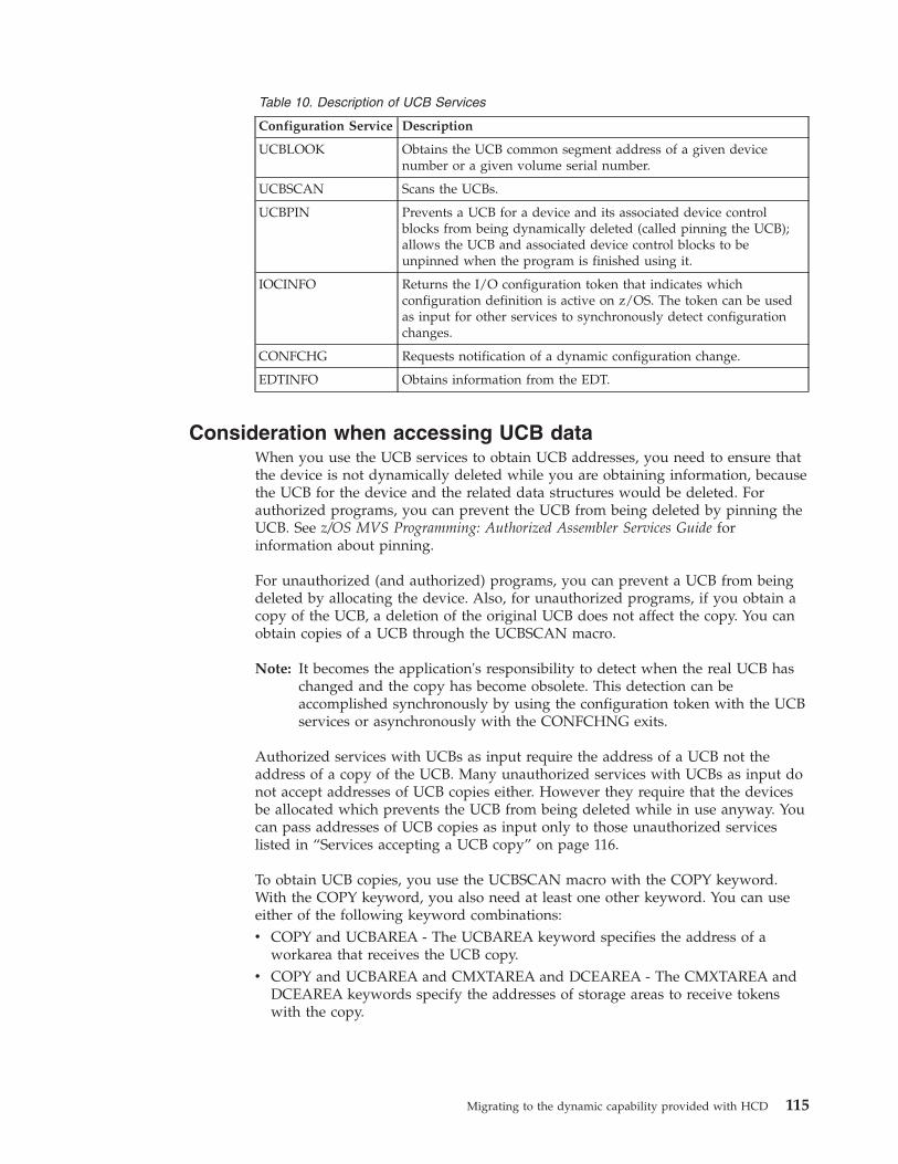
Table 10. Description of UCB Services
Configuration Service Description
UCBLOOK Obtains the UCB common segment address of a given devicenumber or a given volume serial number.
UCBSCAN Scans the UCBs.
UCBPIN Prevents a UCB for a device and its associated device controlblocks from being dynamically deleted (called pinning the UCB);allows the UCB and associated device control blocks to beunpinned when the program is finished using it.
IOCINFO Returns the I/O configuration token that indicates whichconfiguration definition is active on z/OS. The token can be usedas input for other services to synchronously detect configurationchanges.
CONFCHG Requests notification of a dynamic configuration change.
EDTINFO Obtains information from the EDT.
Consideration when accessing UCB dataWhen you use the UCB services to obtain UCB addresses, you need to ensure thatthe device is not dynamically deleted while you are obtaining information, becausethe UCB for the device and the related data structures would be deleted. Forauthorized programs, you can prevent the UCB from being deleted by pinning theUCB. See z/OS MVS Programming: Authorized Assembler Services Guide forinformation about pinning.
For unauthorized (and authorized) programs, you can prevent a UCB from beingdeleted by allocating the device. Also, for unauthorized programs, if you obtain acopy of the UCB, a deletion of the original UCB does not affect the copy. You canobtain copies of a UCB through the UCBSCAN macro.
Note: It becomes the application's responsibility to detect when the real UCB haschanged and the copy has become obsolete. This detection can beaccomplished synchronously by using the configuration token with the UCBservices or asynchronously with the CONFCHNG exits.
Authorized services with UCBs as input require the address of a UCB not theaddress of a copy of the UCB. Many unauthorized services with UCBs as input donot accept addresses of UCB copies either. However they require that the devicesbe allocated which prevents the UCB from being deleted while in use anyway. Youcan pass addresses of UCB copies as input only to those unauthorized serviceslisted in “Services accepting a UCB copy” on page 116.
To obtain UCB copies, you use the UCBSCAN macro with the COPY keyword.With the COPY keyword, you also need at least one other keyword. You can useeither of the following keyword combinations:v COPY and UCBAREA - The UCBAREA keyword specifies the address of a
workarea that receives the UCB copy.v COPY and UCBAREA and CMXTAREA and DCEAREA - The CMXTAREA and
DCEAREA keywords specify the addresses of storage areas to receive tokenswith the copy.
Migrating to the dynamic capability provided with HCD 115
Services accepting a UCB copySome services accept copies and some accept copies but require tokens (fromCMXTAREA and DCEAREA keywords) as part of the copies. The unauthorizedservices that accept copies but do not require tokens as part of the copy are:v LSPACEv TRKCALC
The unauthorized services that accept copies and require tokens as part of the copyare:v CVAFTSTv DEVTYPE
Note: You can use these unauthorized services with UCB copies only with DFSMS.
Use macro IHADFA to check the DFSMS level. CVTDFA points to DFA, which ismapped by macro IHADFA. The DFAREL field contains a two-byte release level.The previously listed services are available only if DFAREL is equal to or greaterthan X'3300'. (You can also use a callable service to check the DFSMS release level;see z/OS DFSMSdfp Advanced Services.)
Specifying devices as dynamic after a migrationDuring migration from MVSCP to HCD, a work IODF is created. How devices aredefined in this IODF is a consideration for using dynamic capability. Also whenyou convert an IODF from MVS/ESA SP 4.1, the same consideration is present. AnIODF in these two scenarios, defines all devices as static by default. That meansthat if the device has support code for dynamic capability the device isinstallation-static. An installation-static device cannot be changed or deleteddynamically in the software definition. Therefore you will probably want tomodify the IODF to override its installation-static default characteristics for specificdevices.
The scope of modification is installation-specific, dependent on installed IBMproducts, other vendor products, and installation applications that are sensitive toI/O configuration changes. The scope of modification also depends on the abilitiesof these products and applications to support and coexist in the new environment.
Use HCD to redefine the devices. For information about how to change devicedefinitions, see z/OS HCD User's Guide.
116 z/OS V1R12.0 HCD Planning
Accessibility
Publications for this product are offered in Adobe Portable Document Format(PDF) and should be compliant with accessibility standards. If you experiencedifficulties when using PDF files, you may view the information through the z/OSInternet Library Web site or the z/OS Information Center. If you continue toexperience problems, send an e-mail to [email protected] or write to:
IBM CorporationAttention: MHVRCFS Reader CommentsDepartment H6MA, Building 7072455 South RoadPoughkeepsie, NY 12601-5400U.S.A.
Accessibility features help a user who has a physical disability, such as restrictedmobility or limited vision, to use software products successfully. The majoraccessibility features in z/OS enable users to:v Use assistive technologies such as screen readers and screen magnifier softwarev Operate specific or equivalent features using only the keyboardv Customize display attributes such as color, contrast, and font size
Using assistive technologiesAssistive technology products, such as screen readers, function with the userinterfaces found in z/OS. Consult the assistive technology documentation forspecific information when using such products to access z/OS interfaces.
Keyboard navigation of the user interfaceUsers can access z/OS user interfaces using TSO/E or ISPF. Refer to z/OS TSO/EPrimer, z/OS TSO/E User's Guide, and z/OS ISPF User's Guide Vol I for informationabout accessing TSO/E and ISPF interfaces. These guides describe how to useTSO/E and ISPF, including the use of keyboard shortcuts or function keys (PFkeys). Each guide includes the default settings for the PF keys and explains how tomodify their functions.
z/OS informationz/OS information is accessible using screen readers with the BookServer or LibraryServer versions of z/OS books in the Internet library at:http://www.ibm.com/systems/z/os/zos/bkserv/
© Copyright IBM Corp. 1989, 2010 117

118 z/OS V1R12.0 HCD Planning
Notices
This information was developed for products and services offered in the U.S.A.
IBM may not offer the products, services, or features discussed in this document inother countries. Consult your local IBM representative for information on theproducts and services currently available in your area. Any reference to an IBMproduct, program, or service is not intended to state or imply that only that IBMproduct, program, or service may be used. Any functionally equivalent product,program, or service that does not infringe any IBM intellectual property right maybe used instead. However, it is the user's responsibility to evaluate and verify theoperation of any non-IBM product, program, or service.
IBM may have patents or pending patent applications covering subject matterdescribed in this document. The furnishing of this document does not give youany license to these patents. You can send license inquiries, in writing, to:
IBM Director of LicensingIBM CorporationNorth Castle DriveArmonk, NY 10504-1785U.S.A
For license inquiries regarding double-byte character set (DBCS) information,contact the IBM Intellectual Property Department in your country or sendinquiries, in writing, to:
Intellectual Property LicensingLegal and Intellectual Property LawIBM Japan, Ltd.1623-14, Shimotsuruma, Yamato-shiKanagawa 242-8502 Japan
The following paragraph does not apply to the United Kingdom or any othercountry where such provisions are inconsistent with local law:INTERNATIONAL BUSINESS MACHINES CORPORATION PROVIDES THISPUBLICATION “AS IS” WITHOUT WARRANTY OF ANY KIND, EITHEREXPRESS OR IMPLIED, INCLUDING, BUT NOT LIMITED TO, THE IMPLIEDWARRANTIES OF NON-INFRINGEMENT, MERCHANTABILITY OR FITNESSFOR A PARTICULAR PURPOSE. Some states do not allow disclaimer of express orimplied warranties in certain transactions, therefore, this statement may not applyto you.
This information could include technical inaccuracies or typographical errors.Changes are periodically made to the information herein; these changes will beincorporated in new editions of the publication. IBM may make improvementsand/or changes in the product(s) and/or the program(s) described in thispublication at any time without notice.
Any references in this information to non-IBM Web sites are provided forconvenience only and do not in any manner serve as an endorsement of those Websites. The materials at those Web sites are not part of the materials for this IBMproduct and use of those Web sites is at your own risk.
© Copyright IBM Corp. 1989, 2010 119
IBM may use or distribute any of the information you supply in any way itbelieves appropriate without incurring any obligation to you.
Licensees of this program who wish to have information about it for the purposeof enabling: (i) the exchange of information between independently createdprograms and other programs (including this one) and (ii) the mutual use of theinformation which has been exchanged, should contact:
Site CounselIBM Corporation2455 South RoadPoughkeepsie, NY 12601-5400USA
Such information may be available, subject to appropriate terms and conditions,including in some cases, payment of a fee.
The licensed program described in this information and all licensed materialavailable for it are provided by IBM under terms of the IBM Customer Agreement,IBM International Program License Agreement, or any equivalent agreementbetween us.
Information concerning non-IBM products was obtained from the suppliers ofthose products, their published announcements or other publicly available sources.IBM has not tested those products and cannot confirm the accuracy ofperformance, compatibility or any other claims related to non-IBM products.Questions on the capabilities of non-IBM products should be addressed to thesuppliers of those products.
All statements regarding IBM's future direction or intent are subject to change orwithdrawal without notice, and represent goals and objectives only.
If you are viewing this information softcopy, the photographs and colorillustrations may not appear.
Policy for unsupported hardwareVarious z/OS elements, such as DFSMS, HCD, JES2, JES3, and MVS, contain codethat supports specific hardware servers or devices. In some cases, thisdevice-related element support remains in the product even after the hardwaredevices pass their announced End of Service date. z/OS may continue to serviceelement code; however, it will not provide service related to unsupportedhardware devices. Software problems related to these devices will not be acceptedfor service, and current service activity will cease if a problem is determined to beassociated with out-of-support devices. In such cases, fixes will not be issued.
TrademarksIBM, the IBM logo, and ibm.com® are trademarks or registered trademarks ofInternational Business Machines Corp., registered in many jurisdictions worldwide.Other product and service names might be trademarks of IBM or other companies.A current list of IBM trademarks is available on the Web at "Copyright andtrademark information" at http://www.ibm.com/legal/copytrade.shtml.
Linux is a trademark of Linus Torvalds in the United States, other countries, orboth.
120 z/OS V1R12.0 HCD Planning

Other product and service names might be trademarks of IBM or other companies.
Notices 121

122 z/OS V1R12.0 HCD Planning
Index
Aabove 16 megabyte UCB
description 49accessibility 117ACTIVATE command
using 84, 85, 88, 95, 103, 104, 105activate new configuration
testing 102activating a new configuration
HCD panel 88alias devices 43alias UCB 43allocation
changing device order 60defining 59device preference table 56EDT 59esoteric device group 54I/O device 53VIO 61
alternate subchannel setdevice definition 40
automatically switchable tape deviceschanging the AUTOSWITCH
attribute 48defining 28description 28planning to use 28
AUTOSWITCH device parameter 48
Bbase devices 43
Ccaptured UCB 49CF peer channel path
reconfiguring 26CF receiver channel path
description 21reconfiguring 25
restrictions 25CF sender channel path
adding dynamically 93changing dynamically 94deleting dynamically 94description 21
channel measurement block (CMB)requirement for devices 76
channel pathaccess list 30adding dynamically 93candidate list 30changing dynamically 94controlling logical partition access 30definition planning 17deleting dynamically 93dynamic I/O characteristic field 90numbering 13
channel path (continued)operation mode 17spanned 35
channel path definitiondescription 37
channel path identifier (CHPID)description 13
channel paths, dynamic management 33channel subsystem
definition planning 16CIB channel path 24CONFIGxx member
updating after dynamic change 83console
devicedynamic 92MCS 92multiple console support 92
NIP 20system 20
control unit 19adding dynamically 95changing dynamically 96deleting dynamically 95description 21dynamic I/O characteristic field 90MIF requirement
logical path 30shared channel path 30
coupling facility (CF)channel paths 21description 21peer channel paths 21specifying logical partition 21
coupling facility control unitdefinition changed 97definition created 97definition deleted 98
coupling facility devicedefinition created 97definition deleted 98
coupling over InfiniBand 24
Ddedicated tape device
description 28device 20
adding dynamically 88allocation
requesting 53changing dynamically 90class 54controlling logical partition access 30defining device features to operating
system 46deleting dynamically 89dynamic 46dynamic I/O characteristic field 90generic name 54installation requirement 83, 88
device (continued)installation-static 46multiple exposure 43parallel access volume 43special 40static 46
device class 54device number
description 42replicating 43
device number alignment 63device preference table
affect on unit affinity 58changing 60description 56
device support codeloading at IPL 78, 88
device typeunsupported 46
direct access storage device (DASD)additional actions for dynamic
change 89, 90disability 117dynamic alias management 45dynamic channel path management 33dynamic configuration
changing characteristic field 90, 94,96
characteristic fieldchannel path 94control unit 96I/O device 90
considerations for z/OS installedproducts 92
creating new IOCDS 82, 83LPAR mode change 84migrating 113performing 83planning 46
dynamic deviceadding 46deleting 46description 46modifying 46redefining to installation-static 48specifying after migration 116
dynamic I/O configurationHSA consideration 74
Eeligible device table (EDT)
defining 59description 4dynamic configuration 61primary 61processing at IPL 78secondary 61
ESCON channel pathlogical address
specifying through HCD 32
© Copyright IBM Corp. 1989, 2010 123
ESCON channel path (continued)processor complex
communication 32shared 32
ESCON CTC control unitlogical address
specifying through HCD 32ESCON requirement
MIF 30shared channel path 30
ESCON switches 15esoteric device group
advantage 56defining 54naming 60required
SYSDA 55SYSSQ 55
specifying order 56
FFibre Channel (FC) switches 15FICON channel
description 37migration 37
CNC to FCV channel paths 37from CNC or FCV to FC channel
paths on the control unit 39
Ggeneric device type
for allocation 54making VIO eligible 61viewing in HCD 61
guest operating systemdynamic configuration 8z/OS under z/VM 8
Hhardware and software configuration
matching 6, 83Hardware Configuration Definition
(HCD)description 2invoking 74
Hardware Configuration Manager (HCM)description 10
hardware system area (HSA)description 6expansion requirement 74
HCD panelActivate New Configuration 73, 88Add Control Unit 35Define Configuration 13Migrate Configuration Data 15Recovery Options 103
HiperSocketschannel path type 41
II/O component
changing definition 88I/O configuration
changing 7defining
overview 2to hardware 2to software 2
defining initially 73defining to hardware 4description 1dynamic change 83dynamically changing 88hardware and software match 6, 83planning decision 11specifying at IPL 73
I/O configuration data set (IOCDS) 26creating new 74, 82, 83description 5
I/O configuration program (IOCP)description 5
I/O control unitdefinition planning 19
I/O definition file (IODF)name 78processing
IPL 76I/O device
definition planning 20initial program load (IPL)
IODF processing 76parameters
managing from a single point ofcontrol 26
initializationconsole
NIP 20NIP console 20
input/output definition file (IODF)description 3dynamically activating 37
installation-static device 104adding 46deleting 46description 46migration consideration 113modifying 46redefining to dynamic 48
Integrated Coupling Migration Facility(ICMF)
configuration considerations 21Intelligent Resource Director (IRD) 33
JJES3 initialization stream checker
providing configuration data 20
Kkeyboard 117
LLOADxx member
SCHSET parameter 81SYSn.IPLPARM 76
LOCANY device parameter 53logical address
ESCON CTC control unit 32specifying through HCD 32
logical control unit (LCU)description 12
logically partitioned (LPAR) modeaccess to channel path 30access to device 30activating change 84continue I/O configuration change
without system reset 105description 12dynamic configuration
activating change 84recovery 104
recover original I/O configurationwith system reset 105without system reset 104
recovery 104
Mmainframe
education xmigration
dynamic configuration 113multiple console support (MCS)
console 92multiple exposure device 43Multiple Image Facility (MIF) capability
comparisonshared channel path 29unshared channel path 29
shared channel path requirementcontrol unit logical path 30ESCON 30
multiple logical channel subsystemsdynamic I/O configuration 99
MVS Configuration Program (MVSCP)migrating to HCD 113
NNotices 119nucleus initialization program (NIP)
console 20
Ooperating system
configuration identifierprocessing at IPL 79
definition planning 15
Pparallel access volume (PAV) 43peer-to-peer remote copy (PPRC)
secondary device 40
124 z/OS V1R12.0 HCD Planning
processorallow dynamic modification
option 74definition planning 16percent expansion option 74
processor configuration tokendescription 6
Processor Resource/System Manager(PR/SM)
LPAR modedynamic configuration 12
production IODFdescription 3name 78
RRACF protection
ACTIVATE command 73recover original I/O configuration
LPAR modewith system reset 105without system reset 104
recoverycontinue I/O configuration change
with reIPL 104without reIPL 104
dynamic configuration change 103procedure 103with reIPL 104without reIPL 104
recover original I/O configurationwith reIPL 104without reIPL 104
replication factordevice number 43
SServer Time Protocol link support 24shared channel path
compared with unshared 29logical partition access 30requirement
control unit logical path 30critical I/O device 30ESCON 30
shortcut keys 117spanned channel path
description 35special device
defining 40restrictions 40
special secondary devicedefining 40, 41restrictions 41
SQAparameter 75requirement for UCBs 75
static devicedescription 46
storage management with above 16megabyte UCBs 49
STP link support 24switch
definition 15
SYS1.PARMLIBLOADxx member 76
SYSDAesoteric device group
required 55SYSn.IPLPARM
LOADxx member 76SYSSQ
esoteric device grouprequired 55
system environmentdynamic configuration
DDR swap 91device 91planning 91
planning 91
Ttape device
assigning in a sysplex 28define automatically switchable 48in a sysplex 28
testingactivation 102
tokenchecking software and hardware
configuration match 6
UUCB service
general method 113limited method 113
unit control block (UCB)alias 43defining above 16 megabytes 49description 4dynamic configuration
storage requirement 75SQA requirement 75
unit information module (UIM)description 4loading at IPL 78, 88
unsupporteddevice 46
Vvalidated work IODF
description 3vary
tape device as automaticallyswitchable 48
virtual I/O data setadvantage 61generic device type
making eligible 61volume
parallel access 43
Wwork IODF
description 3
Zz/OS Basic Skills information center xz890 migration
using HCM 107z990 migration
using HCM 107
Index 125

126 z/OS V1R12.0 HCD Planning


����
Program Number: 5694-A01
Printed in USA
GA22-7525-14