Embed Size (px)
Citation preview

7/25/2019 Handbook - FibeAir IP-20G Advanced Training Course T8.0 ver1.pdf
http://slidepdf.com/reader/full/handbook-fibeair-ip-20g-advanced-training-course-t80-ver1pdf 1/277
Ceragon Course Handbook
www.ceragon.com July 2015
COURSE HANDBOOKCommissioning | Installation | System Configuration
FibeAir IP-20G Training Course
Updated for T8.0
Visit our Customer Training Portal at training.ceragon.com or contact us at [email protected]
Trainee Name: _________________
Copyright 2012 Ceragon Networks Ltd. cts.ceragon.com

7/25/2019 Handbook - FibeAir IP-20G Advanced Training Course T8.0 ver1.pdf
http://slidepdf.com/reader/full/handbook-fibeair-ip-20g-advanced-training-course-t80-ver1pdf 2/277
Version 3
Introduction to Radio Systems
October 2014
Proprietary and Confidential
Agenda
2
Radio Relay Principles
Parameters affecting propagations:
Dispersion
Humidity/gas absorption
Multipath/ducting
Atmospheric conditions (refraction)
Terrain (flatness, type, Fresnel zone clearance, diffraction)
Climatic conditions (rain zone, temperature)
Rain attenuation
Modulation
Page 5

7/25/2019 Handbook - FibeAir IP-20G Advanced Training Course T8.0 ver1.pdf
http://slidepdf.com/reader/full/handbook-fibeair-ip-20g-advanced-training-course-t80-ver1pdf 3/277
Proprietary and Confidential
Digital Transmission Systems
3
Proprietary and Confidential
RF Signal
Path Terrain
f1
f1
Radio Relay Principles
A Radio Link requires two end stations
A line of sight (LOS) or nLOS (near LOS) is required
Microwave Radio Link frequencies occupy 1-80GHz
4
Page 6

7/25/2019 Handbook - FibeAir IP-20G Advanced Training Course T8.0 ver1.pdf
http://slidepdf.com/reader/full/handbook-fibeair-ip-20g-advanced-training-course-t80-ver1pdf 4/277
Proprietary and Confidential
High and Low frequency station
Local site
High station
Remote site
Low station
High station means: Tx(f1) >Rx(f1)
Tx(f1)=11500 MHz Rx(f1)=11500 MHz
Rx(f1)=11000 MHz Tx(f1)=11000 MHz
Low station means: Tx(f1) < Rx(f1)
Full duplex
5
Proprietary and Confidential
Standard frequency plan patterns
Frequency reuse:
2,4V
1,3V1,3H 1,3H 1,3H
Reduced risk for overshoot
Frequency shift:
1,3V1,3H 2,4H
Reduced risk for overshoot
Only Low stations can interfere High stations
1,3H
Tx in upper part of band
Tx in lower part of band
1,3VLow High Low High
6
Tx Tx Tx
TxTxTx
TxTx
TxTx
Tx
Tx
Page 7

7/25/2019 Handbook - FibeAir IP-20G Advanced Training Course T8.0 ver1.pdf
http://slidepdf.com/reader/full/handbook-fibeair-ip-20g-advanced-training-course-t80-ver1pdf 5/277
Proprietary and Confidential
Preferred site location structure
7
Proprietary and Confidential
RF Tx Filter Branching
Network(*) Feeder
Z' B' C' D' A'
Feeder
DBranching
Network(*)
C BRF Rx Filter
A
Receiver
E
Demodulator
Z
Modulator
E'
RECEIVER PATH
TRANSMITTER PATH
Transmitter Digital
Line interface
Digital
Line interface Output
signal
Input
signal
Radio Principal Block Diagram
8
Page 8

7/25/2019 Handbook - FibeAir IP-20G Advanced Training Course T8.0 ver1.pdf
http://slidepdf.com/reader/full/handbook-fibeair-ip-20g-advanced-training-course-t80-ver1pdf 6/277
Proprietary and Confidential
RF Principals
RF - System of communication employing electromagnetic waves(EMW) propagated through space
EMW travel at the speed of light (300,000 km/s)
The wave length is determined by the frequency as follows -
Wave Length
Microwave refers to very short waves (millimeters) and typically
relates to frequencies above 1GHz:
300 MHz ~ 1 meter
10 GHz ~ 3 cm
9
f
c
where c is the propagation velocity of electromagnetic
waves in vacuum (3x10⁸ m/s)
Proprietary and Confidential
RF Principals We can see the relationship between colour, wavelength and amplitude
using this animation
10
Page 9

7/25/2019 Handbook - FibeAir IP-20G Advanced Training Course T8.0 ver1.pdf
http://slidepdf.com/reader/full/handbook-fibeair-ip-20g-advanced-training-course-t80-ver1pdf 7/277
Proprietary and Confidential
Radio Spectrum
11
Parameters Affecting Propagation
12
Page 10

7/25/2019 Handbook - FibeAir IP-20G Advanced Training Course T8.0 ver1.pdf
http://slidepdf.com/reader/full/handbook-fibeair-ip-20g-advanced-training-course-t80-ver1pdf 8/277
Proprietary and Confidential
Parameters Affecting Propagation
Dispersion
Humidity/gas absorption
Multipath/ducting
Atmospheric conditions (refraction)
Terrain (flatness, type, Fresnel zone clearance, diffraction)
Climatic conditions (rain zone, temperature)
Rain attenuation
13
Proprietary and Confidential
Parameters Affecting Propagation Dispersion Electromagnetic signal propagating in a physical medium is degraded
because the various wave components (i.e., frequencies, wavelengths)
have different propagation velocities within the physical medium:
Low frequencies have longer wavelength and refract less
High frequencies have shorter wavelength and refract more
14
Page 11

7/25/2019 Handbook - FibeAir IP-20G Advanced Training Course T8.0 ver1.pdf
http://slidepdf.com/reader/full/handbook-fibeair-ip-20g-advanced-training-course-t80-ver1pdf 9/277
Proprietary and Confidential
Parameters Affecting Propagation Atmospheric Refraction
Deflection of the beam towards the ground due to different electrical
characteristics of the atmospheres is called Dielectric Constant .
The dielectric constant depends on pressure, temperature &
humidity in the atmosphere, parameters that are normally decrease
with altitude
Since waves travel faster through thinner medium, the upper part of the
wave will travel faster than the lower part, causing the beam to bend
downwards, following the curve of earth
15
No Atmosphere
With Atmosphere
Proprietary and Confidential
Wave in atmosphere
16
Page 12

7/25/2019 Handbook - FibeAir IP-20G Advanced Training Course T8.0 ver1.pdf
http://slidepdf.com/reader/full/handbook-fibeair-ip-20g-advanced-training-course-t80-ver1pdf 10/277
Proprietary and Confidential
Parameters Affecting Propagation Multipath
Multipath occurs when there is more then one beam reaching the receiverwith different amplitude or phase
Multipath transmission is the main cause of fading in low frequencies
17
Direct beam
Delayed beam
Proprietary and Confidential
Parameters Affecting Propagation Duct
Atmospheric duct refers to a horizontal layer in the lower atmosphere with
vertical refractive index gradients causing radio signals:
Remain within the duct
Follow the curvature of the Earth
Experience less attenuation in the ducts than they would if the ducts were not
present
18
Duct Layer
Terrain
Duct Layer
Page 13

7/25/2019 Handbook - FibeAir IP-20G Advanced Training Course T8.0 ver1.pdf
http://slidepdf.com/reader/full/handbook-fibeair-ip-20g-advanced-training-course-t80-ver1pdf 11/277
Proprietary and Confidential
Parameters Affecting Propagation - Polarization and
Rain
Raindrops have sizes ranging from 0.1 millimeters to 9 millimeters
mean diameter (above that they tend to break up)
Smaller drops are called cloud droplets, and their shape is spherical.
As a raindrop increases in
size, its shape becomes more
oblate, with its largest
cross-section facing the
oncoming airflow.
19
Large rain drops become
Increasingly flattened on the
Bottom;
very large ones are shaped
like parachutes
Proprietary and Confidential
Parameters Affecting Propagation Rain Fading
Refers to scenarios where signal is absorbed by rain, snow, ice
Absorption becomes significant factor above 11GHz
Signal quality degrades
Represented by dB/km parameter which is related the rain
density which represented mm/hr
Rain drops falls as flattened droplet
V better than H (more immune to rain fading)
20
Page 14

7/25/2019 Handbook - FibeAir IP-20G Advanced Training Course T8.0 ver1.pdf
http://slidepdf.com/reader/full/handbook-fibeair-ip-20g-advanced-training-course-t80-ver1pdf 12/277
Proprietary and Confidential
Parameters Affecting Propagation Rain Fading
21
Heavier rain >> Heavier Atten.
Higher FQ >> Higher Attenuation
Proprietary and Confidential
Parameters Affecting Propagation Fresnel Zone
22
Terrain
Duct Layer0
1st
2nd
3rd
TX RX
1. EMW propagate in beams
2. Some beams widen therefore, their path is longer
3. A phase shift is introduced between the direct and indirect
beam
4. Thus, ring zones around the direct line are created
Page 15

7/25/2019 Handbook - FibeAir IP-20G Advanced Training Course T8.0 ver1.pdf
http://slidepdf.com/reader/full/handbook-fibeair-ip-20g-advanced-training-course-t80-ver1pdf 13/277
Proprietary and Confidential
Parameters Affecting Propagation Fresnel Zone
Obstacles in the first Fresnel zone will create signals that will be 0 to 90 degrees out
of phasein the 2nd zone they will be 90 to 270 degrees out of phasein 3rd zone,
they will be 270 to 450 degrees out of phase and so on
Odd numbered zones are constructive and even numbered zones are destructive.
When building wireless links, we therefore need to be sure that these zones are kept
free of obstructions.
In wireless networking the area containing about 40-60 percent of the first Fresnel
zone should be kept free.
23
Proprietary and Confidential
Example: First condition
24
Page 16

7/25/2019 Handbook - FibeAir IP-20G Advanced Training Course T8.0 ver1.pdf
http://slidepdf.com/reader/full/handbook-fibeair-ip-20g-advanced-training-course-t80-ver1pdf 14/277
Proprietary and Confidential
RF Link Basic Components Parabolic Reflector Radiation (antenna)
25
Proprietary and Confidential
RSSI Curve for RFU-C
1,9V
1,6V
1,3V
-30dBm -60dbm -90dBm
26
Page 17

7/25/2019 Handbook - FibeAir IP-20G Advanced Training Course T8.0 ver1.pdf
http://slidepdf.com/reader/full/handbook-fibeair-ip-20g-advanced-training-course-t80-ver1pdf 15/277
Proprietary and Confidential
Standard performance antennas (SP,LP)
Used for remote access links with low capacity. Re-using frequencies on adjacent links is not
normally possible due to poor front to back ra tio.
High performance antennas (HP)
Used for high and low capac ity links where only one polarization is used. Re-using
frequencies is possible. Can not be used with co-channel systems.
High performance dual polarized antennas (HPX)
Used for high and low capacity links with the possibility to utilize both polarizations. Re-using
frequencies is possible. Can be used for co-channel systems.
Super high performance dual polarized antennas (HSX)
Normally used on high capacity links with the possibility to utilize both polarizations. Re-using
frequencies is possible with high interference protection. Ideal for co-channel systems.
Ultra high performance dual polarized antennas (UHX)
Normally used on high capacity links with high interference requirements. Re-using
frequencies in many directions is possible. Can be used with co-channel systems.
Main Parabolic Antenna Types
27
Proprietary and Confidential
Passive Repeaters
Planereflector
Back-to-backantennas
28
Page 18

7/25/2019 Handbook - FibeAir IP-20G Advanced Training Course T8.0 ver1.pdf
http://slidepdf.com/reader/full/handbook-fibeair-ip-20g-advanced-training-course-t80-ver1pdf 16/277
Proprietary and Confidential
Link Calculation Basic Example (in vacuum)
Lfs
TSL Ga Lfsl Ga Lw
Lb
Lf
RSL
RSL=TSL+Ga‐Lfsl+Ga
‐Lw
‐Lb
‐Lf
RSL ‐ Received Signal Level
TSL Transmitted Signal Level
Lfsl ‐ Free‐space loss = 92.45 + 20 log x(distance in km x frequency in GHz)
Lf ‐ Filter loss
Lb ‐ Branching loss
Lw ‐ Waveguide loss
Ga Antenna gain
29
Proprietary and Confidential
Atmospheric attenuation
][ dBd A aa
Starts to contribute to the total attenuation above approximately 15GHz
Parameters in a:
Frequency
Temperature
Air pressure
Water vapour
30
Page 19
7/25/2019 Handbook - FibeAir IP-20G Advanced Training Course T8.0 ver1.pdf
http://slidepdf.com/reader/full/handbook-fibeair-ip-20g-advanced-training-course-t80-ver1pdf 17/277
Proprietary and Confidential
Objective examples
Typical objectives used in real systems
99.999% Month: 25.9 sec
Year: 5 min 12 sec
99.995 % Month: 2 min 10 sec
Year: 26 min
99.99% Month: 260 sec
Year: 51 min
Performance requirements generally higher than Availability.
ITU use worst month for Performance Average year for Availability
31
Modulation
32
Page 20

7/25/2019 Handbook - FibeAir IP-20G Advanced Training Course T8.0 ver1.pdf
http://slidepdf.com/reader/full/handbook-fibeair-ip-20g-advanced-training-course-t80-ver1pdf 18/277
Proprietary and Confidential
Modulation
Modulation
Analog
Modulation
Digital
Modulation
AM - Amplitude modulation ASK Amplitude Shift Keying
FM - Frequency modulation FSK Frequency Shift Keying
PM Phase modulation PSK Phase Shift Keying
QAM Quadrature Amplitude modulation
33
Proprietary and Confidential
Modem
1 0 1 1 0 1 1 0
1 0 1 1 0 11 0
Modem
1 111 10 0 0
0111 0 11
F1F2F1 F1F2F1 F1
Modem1 1 1 1 10 0 0
1 0 1 1 0 1 1 0
1800 phase shift
ASK modulation changes the amplitude to the analog
signale.1 and 0 have different amplitude.
FSK modulation is a method of represent the two
binary states 1 and 0 with differentspcific frequencies.
PSK modulation changes the phase to the transmittedsignal. The simplest method uses 0 and 1800 .
Digital modulation
34
Page 21

7/25/2019 Handbook - FibeAir IP-20G Advanced Training Course T8.0 ver1.pdf
http://slidepdf.com/reader/full/handbook-fibeair-ip-20g-advanced-training-course-t80-ver1pdf 19/277
Proprietary and Confidential
QAM Modulation
Quadrature Amplitude Modulation employs both phase modulation(PSK) and amplitude modulation (ASK)
The input stream is divided into groups of bits based on the numberof modulation states used.
In 8 QAM, each three bits of input, which provides eight values (0-7)alters the phase and amplitude of the carrier to derive eight uniquemodulation states
In 64 QAM, each six bits generates 64 modulation states; in 128QAM, each seven bits generate 128 states, and so on
4QAM 2bits/symbol 256QAM 8bits/symbol
8QAM 3bits/symbol 512QAM 9bits/symbol
16QAM 4bits/symbol 1024QAM 10bits/symbol
32QAM 5bits/symbol 2048QAM 11bits/symbol
64QAM 6bits/symbol128QAM 7bits/symbol
35
Proprietary and Confidential
Why QAM and not ASK or PSK for higher modulation? This is because QAM achieves a greater distance between adjacent points
in the I-Q plane by distributing the points more evenly
The points on the constellation are more distinct and data errors are
reduced
Higher modulation >> more bits per symbol
Constellation points are closer >>TX is more susceptible to noise
36
Page 22

7/25/2019 Handbook - FibeAir IP-20G Advanced Training Course T8.0 ver1.pdf
http://slidepdf.com/reader/full/handbook-fibeair-ip-20g-advanced-training-course-t80-ver1pdf 20/277
Proprietary and Confidential
Constellation diagram
In a more abstract sense, it represents the possible symbols that may be
selected by a given modulation scheme as points in the complex plane.
Measured constellation diagrams can be used to recognize the type of
interference and distortion in a signal.
37
Proprietary and Confidential
8 QAM Modulation ExampleWe have stream: 001-010-100-011-101-000-011-110
Bit sequence Amplitude Phase (degrees)
000 1 None
001 2 None
010 1 pi/2 (90°)
011 2 pi/2 (90°)
100 1 pi (180°)
101 2 pi (180°)
110 1 3pi/2 (270°)
111 2 3pi/2 (270°)
How does constellation diagram look?
DIGITAL QAM (8QAM)
38
Page 23

7/25/2019 Handbook - FibeAir IP-20G Advanced Training Course T8.0 ver1.pdf
http://slidepdf.com/reader/full/handbook-fibeair-ip-20g-advanced-training-course-t80-ver1pdf 21/277
Proprietary and Confidential
4QAM VS. 16QAM
4QAM 16QAM
39
Proprietary and Confidential
2048 QAM
40
Page 24

7/25/2019 Handbook - FibeAir IP-20G Advanced Training Course T8.0 ver1.pdf
http://slidepdf.com/reader/full/handbook-fibeair-ip-20g-advanced-training-course-t80-ver1pdf 22/277
Proprietary and Confidential
2-PSK
4-PSK
8-PSK
16-QAM
64-QAM
Bandwidth
DecreasesModulation
Complixity
Increases
Bandwidth vs. Modulation
41
Proprietary and Confidential
P o w e r
Noise
Signal
S/N
P o w e r
Noise
S/N
Signal
P o w e r
Noise
S/N
Signal
P o w e r
Noise
S/N
Signal
Example: S/N influence at QPSK Demodulator
Each dot detected in wrong quadrant result in bit errors
BER=10-3BER=10-6BER<10-13BER≈0
Signal / Noise
42
Page 25

7/25/2019 Handbook - FibeAir IP-20G Advanced Training Course T8.0 ver1.pdf
http://slidepdf.com/reader/full/handbook-fibeair-ip-20g-advanced-training-course-t80-ver1pdf 23/277
Proprietary and Confidential
10 -3
10 -4
10 -5
10 -6
10 -7
10-8
-75 -72 -69 -66Receiver input level [dBm]
BER change ratio vs. Noise is
dependent on Noise Power distribution
and coding
BER Impact on Transmission Quality
BER�
43
Proprietary and Confidential
RSL Vs. Threshold
Thermal Noise=10*log(k*T*B*1000)
S/N=23dB for 128QAM (37 MHz)
BER>10-6RSL (dBm)
-20
-30 Nominal Input Level
-99
-96 Receiver amplifies thermal noise
-73 Threshold level BER=10-6
Fading Margin
K Boltzmann constant
T Temperature in Kelvin
B Bandwidth
Time (s)
BER>10-6
44
Page 26

7/25/2019 Handbook - FibeAir IP-20G Advanced Training Course T8.0 ver1.pdf
http://slidepdf.com/reader/full/handbook-fibeair-ip-20g-advanced-training-course-t80-ver1pdf 24/277
Thank you
45
Page 27

7/25/2019 Handbook - FibeAir IP-20G Advanced Training Course T8.0 ver1.pdf
http://slidepdf.com/reader/full/handbook-fibeair-ip-20g-advanced-training-course-t80-ver1pdf 25/277
Page 28

7/25/2019 Handbook - FibeAir IP-20G Advanced Training Course T8.0 ver1.pdf
http://slidepdf.com/reader/full/handbook-fibeair-ip-20g-advanced-training-course-t80-ver1pdf 26/277
Version 3
Introduction to Ethernet
November 2014
Proprietary and Confidential
Agenda
2
Local Area Network (LAN)
Network Devices
OSI Layers
Ethernet Frame
VLAN concept
Page 29

7/25/2019 Handbook - FibeAir IP-20G Advanced Training Course T8.0 ver1.pdf
http://slidepdf.com/reader/full/handbook-fibeair-ip-20g-advanced-training-course-t80-ver1pdf 27/277
Proprietary and Confidential
The Local Area Network (LAN)
3
Proprietary and Confidential
Network Devices
The various devices used to build a data communication network can be classified into type of
equipment depending on how Ethernet packets are forwarded.
HUB
BRIDGE / SWITCH
ROUTER
4
Page 30

7/25/2019 Handbook - FibeAir IP-20G Advanced Training Course T8.0 ver1.pdf
http://slidepdf.com/reader/full/handbook-fibeair-ip-20g-advanced-training-course-t80-ver1pdf 28/277
Proprietary and Confidential
Functions of OSI layers
5
Physical
Data Link
Network
Transport
Session
Presentation
Application
OSI model layers
Type of communication: e-mail, file transfer, web browsing
Encryption, data conversion: ASCII to EBCDIC, BCD to binary et.
Starts, stops sessions. Maintains order
Routes data to different LANs and WANs based on network addresses
Transmits packets from node to node based on station address
Electrical signals and cabling (physical medium)
Ensure delivery of entire file or message
Proprietary and Confidential
Protocols in OSI layers
6
Physical
Data Link
Network
Transport
Session
Presentation
Application
OSI model layers
HTTP, FTP, IRC, SSH, DNS, SNMP
SSL, SFTP, IMAP, SSH, Jpeg, GIF, TIFF, MPEG, MIDI, mp3
VARIOUS APIS, SOCKETS
IP, IP Sec, ICMP, IGMP
Ethernet, Token Ring, SLIP, PPP, FDDI
Coax, Fiber, Wireless
TCP, UDP, ECN, SCTP, DCCP
Page 31

7/25/2019 Handbook - FibeAir IP-20G Advanced Training Course T8.0 ver1.pdf
http://slidepdf.com/reader/full/handbook-fibeair-ip-20g-advanced-training-course-t80-ver1pdf 29/277
Proprietary and Confidential
Ethernet frame
7
Proprietary and Confidential
OSI and TCP/IP model
8
Physical
Data Link
Layer 2,5
Network
Transport
Session
Presentation
Application
Physical
Data Link
Layer 2,5
Network
Transport
Session
Presentation
Application
Network
Interface
Layer 2,5
Internet
ApplicationSession Protocol
Presentation Protocol
Application Protocol
P SFD MAC MPLS IPv4/6 TC P/ UDP DATA FC SS‐VLAN
DATA
MAC MPLS IPv4/6 TCP/UDP DATA FCSS‐VLAN C-VLAN
MP LS I P v4 /6 T CP /U DP D AT A
IP v4/ 6 TC P/ UD P D ATA
T CP /U DP D AT A
TCP/IP modelOSI model
layers
OSI model
layers
E
L
E
L
7 1 12 4 4 4 2 20/40 20/8 4
46-1500P Preamble TCP Transmission control protocolSFD Start frame Delimiter UDP User datagram protocol
MAC = Destination + Source MAC Address FCS Frame check sequenceEL Ether Length/Type
VLAN Virtual local area networkMPLS Multiprotocol Label SwitchingIP Internet protocol
C-VLAN
Size in bytes:
Transport
Page 32

7/25/2019 Handbook - FibeAir IP-20G Advanced Training Course T8.0 ver1.pdf
http://slidepdf.com/reader/full/handbook-fibeair-ip-20g-advanced-training-course-t80-ver1pdf 30/277
Proprietary and Confidential
L2
9
Proprietary and Confidential
L3
10
Page 33

7/25/2019 Handbook - FibeAir IP-20G Advanced Training Course T8.0 ver1.pdf
http://slidepdf.com/reader/full/handbook-fibeair-ip-20g-advanced-training-course-t80-ver1pdf 31/277
Proprietary and Confidential
L4
11
UDP Header
TCP Header
Proprietary and Confidential
Inter-frame gap
Ethernet works in Layer 1, Layer 2 and Layer 2,5
12
Page 34

7/25/2019 Handbook - FibeAir IP-20G Advanced Training Course T8.0 ver1.pdf
http://slidepdf.com/reader/full/handbook-fibeair-ip-20g-advanced-training-course-t80-ver1pdf 32/277
TCP Protocol
13
Proprietary and Confidential
Transmission Control Protocol
14
A TCP packet walks into a bar and
says, Id like a beer.
The bartender replies, You want a
beer?
The TCP packet replies, Yes, Id
like a beer.
Page 35

7/25/2019 Handbook - FibeAir IP-20G Advanced Training Course T8.0 ver1.pdf
http://slidepdf.com/reader/full/handbook-fibeair-ip-20g-advanced-training-course-t80-ver1pdf 33/277
Proprietary and Confidential
Transmission Control Protocol
15
Proprietary and Confidential
TCP- Segment format
16
Page 36

7/25/2019 Handbook - FibeAir IP-20G Advanced Training Course T8.0 ver1.pdf
http://slidepdf.com/reader/full/handbook-fibeair-ip-20g-advanced-training-course-t80-ver1pdf 34/277
Proprietary and Confidential
TCP- Control field
17
Proprietary and Confidential
TCP- Connection establishment using three-way handshake
18
Connectionopened
PassiveopenActive
open
SY N
U AP R S F
seq: 8000
S Y N + AC K UA P R S F
seq : 15000
ac k : 8001
r w nd: 5000
ACK
U AP R S F
seq: 8000a ck : 15001
r w nd : 10000
Means no data !
seq: 8001 if piggybacking
Page 37

7/25/2019 Handbook - FibeAir IP-20G Advanced Training Course T8.0 ver1.pdf
http://slidepdf.com/reader/full/handbook-fibeair-ip-20g-advanced-training-course-t80-ver1pdf 35/277
Proprietary and Confidential
TCP- Numbering System
19
The bytes of data transferred in each connection are numbered.Numbering starts with an arbitrarily generated number.
The value in the sequence number field of a segment defines the
number assigned to the first data byte contained in that segment.
The value of the acknowledgment field in a segment defines the
number of the next byte expected to be received.
Proprietary and Confidential
TCP- Data Transfer
20
Sendrequest
Receive
Receive
Sendrequest
Sendrequest
U AP R S F
seq: 90 0 1
Da t a by t es: 90 0 1-10 0 0 0
U AP R S F
seq: 80 0 1
Da t a by t es: 80 0 1-90 0 0
a ck : 150 0 1
a ck : 150 0 1
U AP R S F
seq: 10 0 0 0 a ck : 17 0 0 1
UA P R S F
seq : 15001
ac k : 10001
Da ta
b y tes: 15001-1 7000
r w nd :10 0 0 0
Connection Termination
Page 38

7/25/2019 Handbook - FibeAir IP-20G Advanced Training Course T8.0 ver1.pdf
http://slidepdf.com/reader/full/handbook-fibeair-ip-20g-advanced-training-course-t80-ver1pdf 36/277
Proprietary and Confidential
TCP- Connection termination using three-way handshake
21
Proprietary and Confidential
TCP- Congestion Control:Slow start, exponential increase
22
cwnd
1
cwnd
2
RTT
cwnd
4
RTT
cwnd
8
RTT
Page 39
7/25/2019 Handbook - FibeAir IP-20G Advanced Training Course T8.0 ver1.pdf
http://slidepdf.com/reader/full/handbook-fibeair-ip-20g-advanced-training-course-t80-ver1pdf 37/277
Proprietary and Confidential
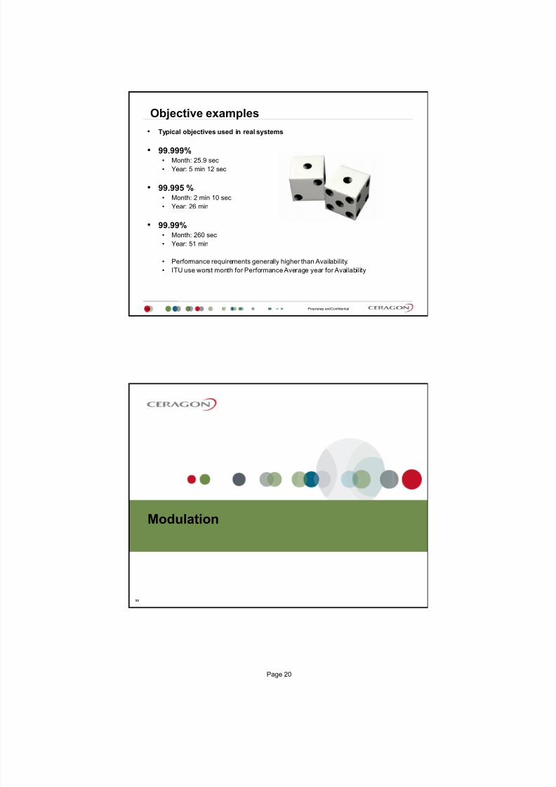
TCP- Congestion Control:Congestion avoidance, additive increase
23
Proprietary and Confidential
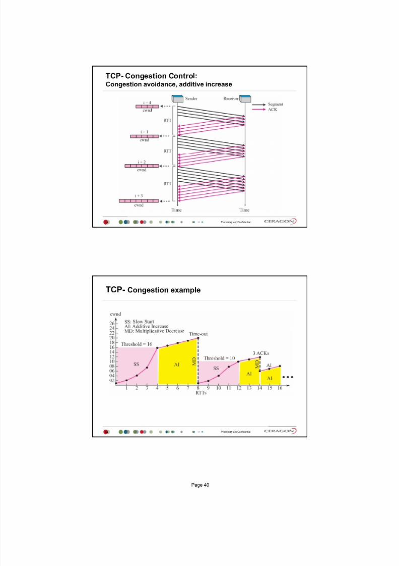
TCP- Congestion example
24
Page 40

7/25/2019 Handbook - FibeAir IP-20G Advanced Training Course T8.0 ver1.pdf
http://slidepdf.com/reader/full/handbook-fibeair-ip-20g-advanced-training-course-t80-ver1pdf 38/277
Proprietary and Confidential
TCP- Calculating maximum throughput of one TCP stream
25
* Example:
TCP ideal window size = 1*109*30*10-3 /8 = 3.75MBytes
TCP window size [Bytes] = Bandwidth [bps] * RTD [Sec] /8
VLAN concept
Page 41

7/25/2019 Handbook - FibeAir IP-20G Advanced Training Course T8.0 ver1.pdf
http://slidepdf.com/reader/full/handbook-fibeair-ip-20g-advanced-training-course-t80-ver1pdf 39/277
Proprietary and Confidential
Virtual Local Area Network (VLAN) concept
27
Imagine that you have a network and three different customer
Customer 1
Customer 2
Customer 3
NETWORK
Proprietary and Confidential
Virtual Local Area Network (VLAN) concept
28
The most common protocol used today in configuring virtual LANs is IEEE 802.1Q
VLANs are created to provide the segmentation services traditionally provided by routers
in LAN configurations
Page 42

7/25/2019 Handbook - FibeAir IP-20G Advanced Training Course T8.0 ver1.pdf
http://slidepdf.com/reader/full/handbook-fibeair-ip-20g-advanced-training-course-t80-ver1pdf 40/277
Proprietary and Confidential
OSI and TCP/IP model
Physical
Data Link
Layer 2,5
Network
Transport
Session
Presentation
Application
Physical
Data Link
Layer 2,5
Network
Transport
Session
Presentation
Application
Network
Interface
Layer 2,5
Internet
ApplicationSession Protocol
Presentation Protocol
Application Protocol
P SFD MAC MPLS IPv4/6 TC P/ UDP DATA FC SS‐VLAN
DATA
MAC MPLS IPv4/6 TCP/U DP D ATA FCSS‐VLAN C-VLAN
MP LS I P v4 /6 T CP /U DP D AT A
IP v4/ 6 TC P/ UD P D ATA
T CP /U DP D AT A
TCP/IP modelOSI model
layers
OSI model
layers
E
L
E
L
7 1 12 4 4 4 2 20/40 20/8 4
46-1500P Preamble TCP Transmission control protocol
SFD Start frame Delimiter UDP User datagram protocolMAC = Destination + Source MAC Address FCS Frame check sequence
EL Ether Length/Type
VLAN Virtual local area networkMPLS Multiprotocol Label Switching
IP Internet protocol
C-VLAN
Size in bytes:
Transport
29
Proprietary and Confidential
Ethernet frame
30
Page 43
7/25/2019 Handbook - FibeAir IP-20G Advanced Training Course T8.0 ver1.pdf
http://slidepdf.com/reader/full/handbook-fibeair-ip-20g-advanced-training-course-t80-ver1pdf 41/277
Proprietary and Confidential
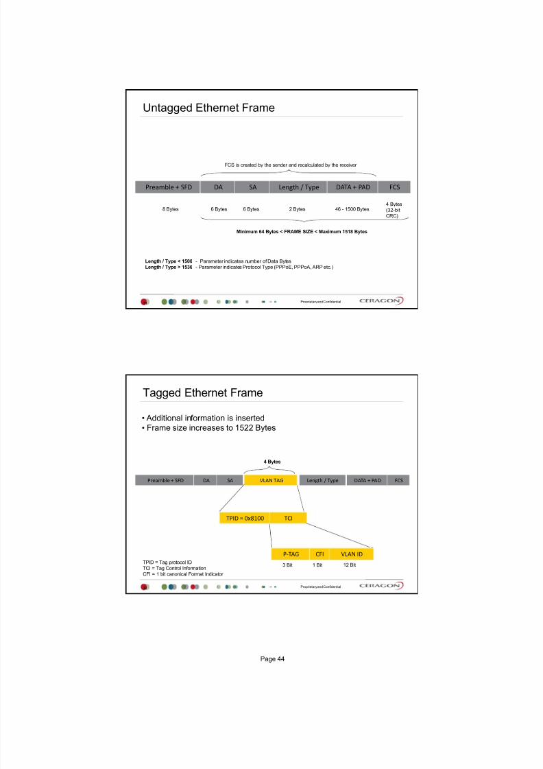
Length / Type < 1500 - Parameter indicates number of Data Bytes
Length / Type > 1536 - Parameter indicates Protocol Type (PPPoE, PPPoA, ARP etc.)
Preamble + SFD DA SA Length / Type DATA + PAD FCS
6 Bytes 6 Bytes8 Bytes 2 Bytes 46 - 1500 Bytes4 Bytes
(32-bit
CRC)
FCS is created by the sender and recalculated by the receiver
Minimum 64 Bytes < FRAME SIZE < Maximum 1518 Bytes
Untagged Ethernet Frame
31
Proprietary and Confidential
Additional information is inserted
Frame size increases to 1522 Bytes
Tagged Ethernet Frame
4 Bytes
TPID = Tag protocol ID
TCI = Tag Control Information
CFI = 1 bit canonical Format Indicator
Preamble + SFD DA SA Length / Type DATA + PAD FCS
3 Bit 1 Bit 12 Bit
TCI
CFI
VLAN TAG
P‐TAG VLAN ID
TPID = 0x8100
32
Page 44

7/25/2019 Handbook - FibeAir IP-20G Advanced Training Course T8.0 ver1.pdf
http://slidepdf.com/reader/full/handbook-fibeair-ip-20g-advanced-training-course-t80-ver1pdf 42/277
Proprietary and Confidential
VLAN ID uses 12 bits, therefore the number of maximum VLANs is 4096:
212 = 4096
VID 0 = reserved
VID 4090-4096 = reserved (dedicated for IP-10s internal purposes such as MNG etc.)
VID 1 = default
After tagging a frame, FCS is recalculated
CFI is set to 0 for ETH frames, 1 for Token Ring to allow TR frames over
ETH backbones (some vendors may use CFI for internal purposes)
Tagging a Frame
33
Proprietary and Confidential
TPID / ETHER-Type / Protocol Type
34
TPID in tagged frames in always set to
0x8100
It is important that you understand the
meaning and usage of this parameter
Protocol type Value
Tagged Frame 0x8100
ARP 0x0806
Q ‐in‐Q (CISCO) 0x8100
Q ‐in‐Q (other vendors) 0x88A8
Q ‐in‐Q (other vendors) 0x9100
Q ‐in‐Q (other vendors) 0x9200
RARP 0x8035
IP 0x0800
IPv6 0x86DD
PPPoE 0x8863/0x8864
MPLS 0x8847/0x8848
IS‐IS 0x8000
LACP 0x8809
802.1x 0x888E
Page 45

7/25/2019 Handbook - FibeAir IP-20G Advanced Training Course T8.0 ver1.pdf
http://slidepdf.com/reader/full/handbook-fibeair-ip-20g-advanced-training-course-t80-ver1pdf 43/277
Proprietary and Confidential
Additional VLAN (S-VLAN) is inserted
Frame size increases to 1526 Bytes
Q-in-Q
4 Bytes
Preamble + SFD DA SA Length / Type DATA + PAD FCS
3 Bit 1 Bit 12 Bit
CFI
S ‐ VLAN
TPID = 0x88A8
P‐TAG VLAN ID
TCI
CFI P‐TAGVLAN ID
TCITPID = 0x8100
C ‐ VLAN
4 Bytes
3 Bit 1 Bit 12 Bit
35
Thank you
36
Page 46

7/25/2019 Handbook - FibeAir IP-20G Advanced Training Course T8.0 ver1.pdf
http://slidepdf.com/reader/full/handbook-fibeair-ip-20g-advanced-training-course-t80-ver1pdf 44/277
Version 4
IP-20G Overview
July 2015
Proprietary and Confidential
Agenda
2
FibeAir IP-20 Product Family
Network topology with IP-20G
IP-20G Introduction and Highlights
IP-20G Front Panel Description
IP-20G Block Diagram
Page 47

7/25/2019 Handbook - FibeAir IP-20G Advanced Training Course T8.0 ver1.pdf
http://slidepdf.com/reader/full/handbook-fibeair-ip-20g-advanced-training-course-t80-ver1pdf 45/277
Proprietary and Confidential
FibeAir IP-20 Product Family
3
IP-20Platform
IP-20LH
IP-20A= IP20N + RFU-A
Available only for US & NA market
IP-20N 1RU & 2RU
IP-20G
IP-20S
IP-20C
IP-20E
IP-20GX
Proprietary and Confidential
IP-10CIP-10EIP-10G
Ethernet + Optional TDM
IP-10Q
Ethernet Only
Compact
All-OutdoorTerminal /
Single-Carrier
Nodal
Terminal /
Single-Carrier
NodalAggregation
FibeAir IP-10 Product Line - 2011
Optimized for Full GE
Multi-Carrier pipesUltra-high density
Optimized Solution for Any Network
4
Page 48
7/25/2019 Handbook - FibeAir IP-20G Advanced Training Course T8.0 ver1.pdf
http://slidepdf.com/reader/full/handbook-fibeair-ip-20g-advanced-training-course-t80-ver1pdf 46/277
Proprietary and Confidential
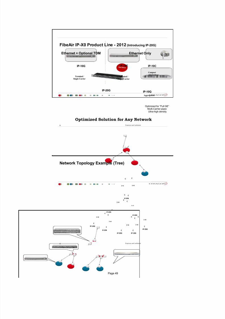
IP-10CIP-10EIP-10G
Optimized for Full GE
Multi-Carrier pipesUltra-high density
Ethernet + Optional TDM
IP-10Q
Optimized Solution for Any Network
Ethernet Only
FibeAir IP-X0 Product Line - 2012 (Introducing IP-20G)
Compact
All-OutdoorTerminal /
Single-CarrierTerminal /
Single-Carrier
Aggregation
IP-20G
5
Proprietary and Confidential
IP‐20N
IP‐20N
IP‐20N
IP‐20G
Network Topology Example (Tree)
6
C
C
C
C
C
C
C
1+1
2+0
1+1
IP‐10G
C
C
IP‐20G
C
C
1+0
1+02+0IP‐10G
C
C
1+0
C
2+0
C
C
1+0
IP‐20N
C
Page 49

7/25/2019 Handbook - FibeAir IP-20G Advanced Training Course T8.0 ver1.pdf
http://slidepdf.com/reader/full/handbook-fibeair-ip-20g-advanced-training-course-t80-ver1pdf 47/277
Proprietary and Confidential
IP-20G Introduction
7
IP-20G hardware characteristics:
6 x 1 GE interfaces total
2 x dual mode GE elec trical or cascading interfaces (RJ-45)
2 x GE electrical interfaces (RJ-45)
2x GE optical interfaces (SFP)
Optional: 16 x E1 interfaces
Single or dual radio interfaces (TNC)
Single or dual power-feeds (-48v)
Sync in/out interface
Management interfaces
Terminal RS232 (RJ-45)
2x FE electrical interfaces (RJ-45)
External alarms interface
RFU-C/Ce, RFU-HP (1Rx or 2Rx), RFU-Ae/Aep support
IEEE-1588 TC
IP-20G maintains high capacity, with up to 1024QAM modulation in its first SW release (T7.7),and up to 2048QAM from SW release T8.0
Proprietary and Confidential
IP-20G Highlights
8
Optimized tail/edge solution supporting seamless integration of radio (L1)
and end-to-end Carrier Ethernet transport/services (L2) functionality
Rich packet processing feature set for support of engineered end-to-end
Carrier Ethernet services with strict SLA
Integrated support for multi-operator and converged backhaul business
models, such as wholesale services and RAN-sharing
Highest capacity, scalability and spectral efficiency
High precision, flexible packet synchronization solution combining SyncE
and 1588v2
Best-in-class integrated TDM migration solution
Specifically built to support resilient and adaptive multi-carrier radio links,scaling to GE capacity
Future-proof with maximal investment protection
Supports RFU-Ce for modulations up to 2048QAM.
Page 50

7/25/2019 Handbook - FibeAir IP-20G Advanced Training Course T8.0 ver1.pdf
http://slidepdf.com/reader/full/handbook-fibeair-ip-20g-advanced-training-course-t80-ver1pdf 48/277
Reference Configurations
9
Proprietary and Confidential
IP-20G Dual Modem Activation
10
A single-carrier IP-20G unit with dual-modem hardware can be converted via
software upgrade to a dual-modem unit
Page 51

7/25/2019 Handbook - FibeAir IP-20G Advanced Training Course T8.0 ver1.pdf
http://slidepdf.com/reader/full/handbook-fibeair-ip-20g-advanced-training-course-t80-ver1pdf 49/277
Proprietary and Confidential
IP-20G IDU Cascading with Dual Modems
11
A dual-modem IP-20G in an East-West configuration, with a cascading link to a pair
of IP-20G units
A cascading connection between these two units enables hybrid Ethernet/TDM traffic
to pass among all three units
Proprietary and Confidential
IP-20G Chained Network
12
Page 52

7/25/2019 Handbook - FibeAir IP-20G Advanced Training Course T8.0 ver1.pdf
http://slidepdf.com/reader/full/handbook-fibeair-ip-20g-advanced-training-course-t80-ver1pdf 50/277
Proprietary and Confidential
IP-20G Ring with Spur
13
A ring consisting of three IP-20G nodes connected via 1+0 radio links, with a spur to
a fourth IP-20G node
All of the IP-20G units in the ring utilize dual-modem configurations, except for the
node at the bottom in the figure
Proprietary and Confidential
IP-20G Aggregation/POP Site
14
Page 53

7/25/2019 Handbook - FibeAir IP-20G Advanced Training Course T8.0 ver1.pdf
http://slidepdf.com/reader/full/handbook-fibeair-ip-20g-advanced-training-course-t80-ver1pdf 51/277
IP-20G Front Panel Description
15
Proprietary and Confidential
FibeAir IP-20G Front panel description
16
Terminal(RJ45)
ExternalAlarms(DB9)
16 x E1/DS1s(optional)
MDR69 connector
Sync in/out(RJ45)
2 x GEElectrical(RJ45)
2 x GEOptical(SFP)
1 or 2 RFUinterfaces
(TNC)
Power -48V DC
(Single-feed &
Dual-feed options)
2 x FEManagement via
splitter cable(RJ45)
Purpose-built for tail/edge nodal sites
Same features/capabilities as IP-20N/A Aggregation Nodes
1RU
2 x Dual-Mode:GE Electrical orCascading
(RJ45)
Passive cooling
(Fan-less design)
Page 54
7/25/2019 Handbook - FibeAir IP-20G Advanced Training Course T8.0 ver1.pdf
http://slidepdf.com/reader/full/handbook-fibeair-ip-20g-advanced-training-course-t80-ver1pdf 52/277
Proprietary and Confidential
SM- Card
17
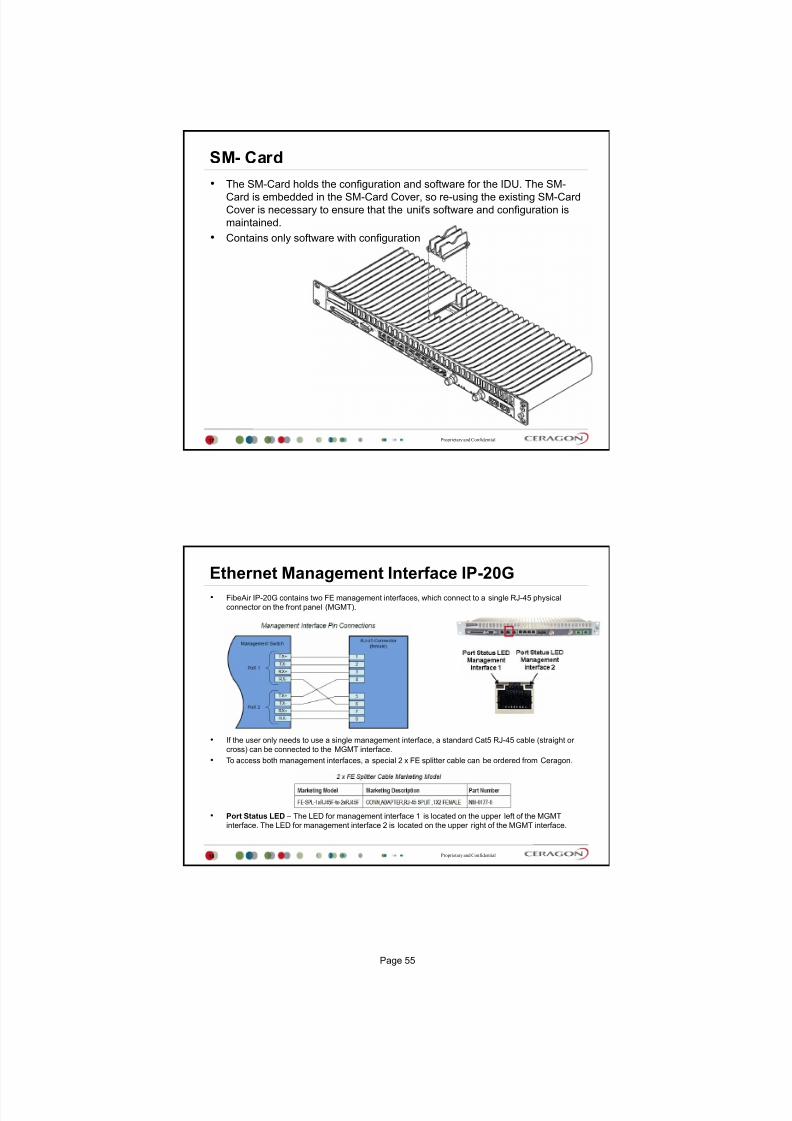
The SM-Card holds the configuration and software for the IDU. The SM-
Card is embedded in the SM-Card Cover, so re-using the existing SM-Card
Cover is necessary to ensure that the units software and configuration is
maintained.
Contains only software with configuration
Proprietary and Confidential
Ethernet Management Interface IP-20G
18
FibeAir IP-20G contains two FE management interfaces, which connect to a single RJ-45 physical
connector on the front panel (MGMT).
If the user only needs to use a single management interface, a standard Cat5 RJ-45 cable (straight or
cross) can be connected to the MGMT interface.
To access both management interfaces, a special 2 x FE splitter cable can be ordered from Ceragon.
Port Status LED The LED for management interface 1 is located on the upper left of the MGMT
interface. The LED for management interface 2 is located on the upper right of the MGMT interface.
Page 55

7/25/2019 Handbook - FibeAir IP-20G Advanced Training Course T8.0 ver1.pdf
http://slidepdf.com/reader/full/handbook-fibeair-ip-20g-advanced-training-course-t80-ver1pdf 53/277
Proprietary and Confidential
E1/DS1 - Interface
19
Optionally, FibeAir IP-20G can be ordered with an MDR69 connector in which 16
E1/DS1 interfaces are available (ports 1 through 16).
In SW 7.7. is E1 option only available
In SW 7.9. also DS1 option available
The E1/DS1 interface has the following LEDs
ACT LED Indicates whether the TDM card is working properly (Green) or if there is
an error or a problem with the card s functionality (Red).
E1/DS1 LED Indicates whether the interfaces are enabled with no alarms (Green),
with alarms (Red), or no interfaces enabled (Off).
Proprietary and Confidential
Radio Interfaces
20
In 7.7 is supported only single radio carrier.
In 7.7.5 is supported 2x 1+0 East / West Terminal
In 7.9 is supported 2+0 XPIC
In 7.7 is supported only RFU-C (up to 256QAM) and RFU-Ce (up to 1024
QAM)
In 7.9 RFU-HP, 1500HP, RFU-A supported
In 8.0 release is supported 2+0 ABC
The IDU and RFU are connected by a coaxial cable RG-223 (100 m/300 ft),
Belden 9914/RG-8 (300 m/1000 ft) or equivalent, with an N-type connector
(male) on the RFU and a TNC connector on the IDU.
RFU-C / RFU-Ce RFU-HP / 1500HP RFU-A
Page 56

7/25/2019 Handbook - FibeAir IP-20G Advanced Training Course T8.0 ver1.pdf
http://slidepdf.com/reader/full/handbook-fibeair-ip-20g-advanced-training-course-t80-ver1pdf 54/277
Proprietary and Confidential
Radio Interfaces - LEDs
21
ACT Indicates whether the interface is working properly (Green) or if there isan error or a problem with the interfaces functionality (Red), as follows:
Off The radio is disabled.
Green The radio is active and operating normally.
Blinking Green The radio is operating normally and is in standby mode.
Red There is a hardware failure.
Blinking Red Troubleshooting mode.
LINK Indicates the status of the radio link, as follows:
Green The radio link is operational.
Red There is an LOF or Excessive BER alarm on the radio.
Blinking Green An IF loopback is activated, and the result is OK.
Blinking Red An IF loopback is activated, and the result is Failed.
RFU Indicates the status of the RFU, as follows:
Green The RFU is functioning normally.
Yellow A minor RFU alarm or a warning is present, or the RFU is in TXmute mode, or, in a protected configuration, the RFU is in standby mode.
Red A cable is disconnected, or a major or critical RFU alarm is present. Blinking Green An RF loopback has been activated, and the result is OK.
Blinking Red An RF loopback has been activated, and the result isFailed.
Proprietary and Confidential
Power Interfaces
22
FibeAir IP-20G receives an external supply of -48V current via one or two power
interfaces (the second power interface is optional for power redundancy).
The IP-20G monitors the power supply for under-voltage and includes reverse
polarity protection, so that if the positive (+) and negative (-) inputs are mixed up, the
system remains shut down.
The allowed power input range for the IP-20G is -40V to -60V. An under voltage
alarm is triggered if the power goes below the allowed range, and an over voltage
alarm is triggered if the power goes above the allowed range.
There is an ACT LED for each power interface.
The LED is Green when the voltage being fed to the power interface is within range,
and Red if the voltage is not within range or if a power cable is not connected.
Page 57

7/25/2019 Handbook - FibeAir IP-20G Advanced Training Course T8.0 ver1.pdf
http://slidepdf.com/reader/full/handbook-fibeair-ip-20g-advanced-training-course-t80-ver1pdf 55/277
Proprietary and Confidential
Synchronization Interface
23
FibeAir IP-20G includes an RJ-45 synchronization interface for T3 clock input and T4 clock output.
The interface is labeled SYNC.
The synchronization interface contains two LEDs, one on the upper left of the interface and one
on the upper right of the interface, as follows:
T3 Status LED Located on the upper left of the interface. Indicates the status of T3 input clock,
as follows:
Off There is no T3 input clock, or the input is illegal.
Green There is legal T3 input clock.
T4 Status LED Located on the upper right of the interface. Indicates the status of T4 output
clock, as follows:
Off T4 output clock is not available.
Green T4 output clock is available.
Blinking Green The clock unit is in a holdover state.
Proprietary and Confidential
External Alarms
24
IP-20G includes a DB9 dry contact external alarms interface. The external alarms
interface supports five input alarms and a single output alarm.
The input alarms are configurable according to:
1 Intermediate
2 Critical
3 Major
4 Minor
5 Warning
The output alarm is configured according to predefined categories.
Page 58

7/25/2019 Handbook - FibeAir IP-20G Advanced Training Course T8.0 ver1.pdf
http://slidepdf.com/reader/full/handbook-fibeair-ip-20g-advanced-training-course-t80-ver1pdf 56/277
Proprietary and Confidential
Terminal Interface
25
FibeAir IP-20G includes an RJ-45 terminal interface (RS-232). A local craft
terminal can be connected to the terminal interface for local CLI
management of the unit.
Bits per Second 115,200
Data Bits 8
Parity None
Stop Bits 1
Flow Control - None
Proprietary and Confidential
IP-20G Block Diagram
26
Page 59

7/25/2019 Handbook - FibeAir IP-20G Advanced Training Course T8.0 ver1.pdf
http://slidepdf.com/reader/full/handbook-fibeair-ip-20g-advanced-training-course-t80-ver1pdf 57/277
Proprietary and Confidential
Unique Feature Set
27
Extended Modulations Range ACM
4‐
2048QAM
(11 ACM points)
Frequency bands 6‐42GHz
Wide range of channels10, 20, 30, 40, 50, 60MHz (FCC)
7, 14, 28, 40, 56MHz (ETSI)
System Configurations
1+0
2x 1+0 EW
1+1 HSB
2+0 XPIC
2+0 ABC
Traffic ManagerTraffic Aware Smart Pipe
Multi Service, Carrier Ethernet 2.0 Switch
Radio Connection RFU‐C, RFU‐Ce, 1500HP, RFU‐HP, RFU‐A
Thank You
28
Page 60

7/25/2019 Handbook - FibeAir IP-20G Advanced Training Course T8.0 ver1.pdf
http://slidepdf.com/reader/full/handbook-fibeair-ip-20g-advanced-training-course-t80-ver1pdf 58/277
IP-20G
December 2014
Radio Frequency Units
V1
1
Proprietary and Confidential
Agenda
2
Radio Frequency units for IP20
RFU Selection Guide
RFU-C
1500HP / RFU HP
Split Mount Configuration and Branching
New Outdoor Circulator Block OCB
Split Mount Configurations
Page 61

7/25/2019 Handbook - FibeAir IP-20G Advanced Training Course T8.0 ver1.pdf
http://slidepdf.com/reader/full/handbook-fibeair-ip-20g-advanced-training-course-t80-ver1pdf 59/277
Proprietary and Confidential
Radio Frequency units
3
Standard Power
FibeAir RFU-C
High Power
FibeAir 1500HP SD
FibeAir RFU-HP
The following RFUs can be installed in a split-mount configuration:
FibeAir RFU-C (6 42 GHz)
FibeAir 1500HP (6 11 GHz)
RFU-HP (6 8 GHz)
The following RFUs can be installed in an all-indoor configuration:
FibeAir 1500HP/RFU-HP (6 11 GHz)
The IDU and RFU are connected by a coaxial cable RG-223 (up to 100 m/300 ft),Belden 9914/RG-8 (up to 300 m/1000 ft) or equivalent, with an N-type connector(male) on the RFU and a TNC connector on the RMC in the IP-20N chassis.
Proprietary and Confidential
Ultra High Power (Max 33 dbm)
6-8 GHz
7-56Mhz Ch. Bandwidth
Low Loss Chaining
QPSK-2048QAM
Standard Power (Max 24 dbm)
6-42 GHz
7-56Mhz Ch. Bandwidth
QPSK-2048QAM
Very Compact
FibeAir ® Radio Frequency Units
4
FibeAir RFU-C
FibeAir RFU-HP - 1RX
HighPower (Max 33 dbm)
6-11 GHz
10-40Mhz Ch. Bandwidth
QPSK-2048QAM
Low Loss Chaining
Dual RX with IFC (Single Rx available for 11GHz)
FibeAir 1500-HP/SD
Page 62
7/25/2019 Handbook - FibeAir IP-20G Advanced Training Course T8.0 ver1.pdf
http://slidepdf.com/reader/full/handbook-fibeair-ip-20g-advanced-training-course-t80-ver1pdf 60/277
Proprietary and Confidential
RFU Selection Guide
5
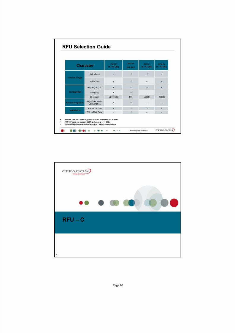
Character 1500HP
(6 11 GHz)
RFU‐HP
(6‐8 GHz)
RFU‐C
(6 42 GHz)
RFU‐Ce
(6 42 GHz)
Installation Type
Split Mount √ √ √ √
All‐Indoor √ √
Configuration
1+0/2+0/1+1/2+2 √ √ √ √
N+0 ( N>2) √ √
SD support √ (IFC, BBS) BBS √ (BBS) √ (BBS)
Power Saving Mode Adjustable Power
Consumption √ √
Modulation
QPSK to 256 QAM √ √ √ √
512 to 2048 QAM √ √ √
1500HP 1RX for 11GHz supports channel bandwidth 10-30 MHz
RFU-HP does not support 56 MHz channels at 11 GHz
IFC at 40MHz is supported only for the 11GHz frequency band
RFU C
6
Page 63

7/25/2019 Handbook - FibeAir IP-20G Advanced Training Course T8.0 ver1.pdf
http://slidepdf.com/reader/full/handbook-fibeair-ip-20g-advanced-training-course-t80-ver1pdf 61/277
Proprietary and Confidential
RFU C 6-42GHz
7
Standard RFU C
Support up to 256 QAM modulation
Premium RFU-Ce
Support up to 1024 QAM modulation
RMC-B is required for radio link with IP-20N
Main Features of RFU-C:
Frequency range Operates in the frequency range 6 42 GHz
More power in a smaller package - Up to 26 dBm for extended distance, enhancedavailability, use of smaller antennas
Configurable Modulation QPSK 1024 QAM
Configurable Channel Bandwidth 7 MHz 56MHz
Compact, lightweight form factor - Reduces installation and warehousing costs
Supported configurations:
1+0 direct and remote mount
1+1 direct and remote mount
2+0 direct and remote mount
2+2 remote mount
4+0 remote mount
Efficient and easy
Proprietary and Confidential
Example of RFU-C direct 1+1 mount configurations
8
1+1 direct
Page 64

7/25/2019 Handbook - FibeAir IP-20G Advanced Training Course T8.0 ver1.pdf
http://slidepdf.com/reader/full/handbook-fibeair-ip-20g-advanced-training-course-t80-ver1pdf 62/277
Proprietary and Confidential
Orthogonal Mode Transducer (OMT) Installation for 2+0 Configuration
9
Switch to the circular adaptor
(removing the
existing rectangular transition,
swapping the O-ring, and
replacing on the circular
transition).
Proprietary and Confidential
OMT Installation Example
10
Note: RFUs are at sub 11GHz band
Page 65

7/25/2019 Handbook - FibeAir IP-20G Advanced Training Course T8.0 ver1.pdf
http://slidepdf.com/reader/full/handbook-fibeair-ip-20g-advanced-training-course-t80-ver1pdf 63/277
1500HP / RFU HP
11
Proprietary and Confidential
Main Features of 1500HP/RFU-HP Frequency range:
1500HP 2RX: 6-11GHz
1500HP 1RX: 11GHz
RFU-HP 1RX: 6-8GHz
Frequency source Synthesizer
Installation type Split mount remote mount, all indoor (No direct mount)
Diversity Optional innovative IF Combining Space Diversity for improved system gain (for 1500HP), as
well as BBS Space Diversity (all models)
High transmit power Up to 33dBm in all indoor and split mount installations
Configurable Modulation QPSK 1024 QAM
Configurable Channel Bandwidth
1500HP 2RX (6-11 GHz): 10-30 MHz
1500HP 1RX (11 GHz): 10-30 MHz
1500HP 1RX (11 GHz wide): 24-40 MHz
RFU-HP 1RX (6-8GHz): 7-56 MHz
System Configurations Non-Protected (1+0), Protected (1+1), Space Diversity, 2+0/2+2 XPIC, N+0, N+1
XPIC and CCDP Built-in XPIC (Cross Polarization Interference Canceller) and Co-Channel Dual Polarization
(CCDP) feature for double transmission capacity, and more bandwidth efficiency Power Saving Mode option - Enables the microwave system to automatically detect when link conditions allow it
to use less power (for RFU-HP)
Tx Range (Manual/ATPC) Up to 20 dB dynamic range
ATPC (Automatic Tx Power Control)
RF Channel Selection Via EMS/NMS
NEBS Level 3 NEBS compliance
12
Page 66

7/25/2019 Handbook - FibeAir IP-20G Advanced Training Course T8.0 ver1.pdf
http://slidepdf.com/reader/full/handbook-fibeair-ip-20g-advanced-training-course-t80-ver1pdf 64/277
Proprietary and Confidential
1500 HP 2RX in 1+0 SD Configuration
13
Proprietary and Confidential
1500 HP 1RX in 1+0 SD Configuration
14
Page 67

7/25/2019 Handbook - FibeAir IP-20G Advanced Training Course T8.0 ver1.pdf
http://slidepdf.com/reader/full/handbook-fibeair-ip-20g-advanced-training-course-t80-ver1pdf 65/277
Proprietary and Confidential
RFU-HP 1RX in 1+0 SD Configuration
15
Proprietary and Confidential
HP Comparison Table
16
Feature 1500HP 2RX 1500HP 1RX RFU‐HP Notes
Frequency Bands Support 6L,6H,7,8,11GHz 6L,6H,7,8,11GHz 6L,6H,7,8GHz
Channel Spacing Support Up to 30 MHzUp to 30 MHz
11 GHz version for
40 MHzUp to 56 MHz
Split‐Mount √ √ √ All are compatible with OCBs
from both generations
All‐Indoor √ √ √ All are compatible with ICBs
Space Diversity BBS and IFC BBS BBS IFC ‐ IF Combining
BBS ‐ Base Band Switching
Frequency Diversity √ √ √
1+0/2+0/1+1/2+2 √ √ √
N+1 √ √ √
N+0 ( N>2) √ √ √
High
Power √ √ √
Remote Mount Antenna √ √ √
Power Saving Mode ‐‐ ‐‐ √Power consumption changes
with TX power
1500 HP (11 GHz ) 40 MHz bandwidth does not support IF Combining. For this frequency, space diversity is only available via BBS.
Page 68
7/25/2019 Handbook - FibeAir IP-20G Advanced Training Course T8.0 ver1.pdf
http://slidepdf.com/reader/full/handbook-fibeair-ip-20g-advanced-training-course-t80-ver1pdf 66/277
Split Mount Configuration and Branching
Proprietary and Confidential
Split Mount Configuration and Branching Network
18
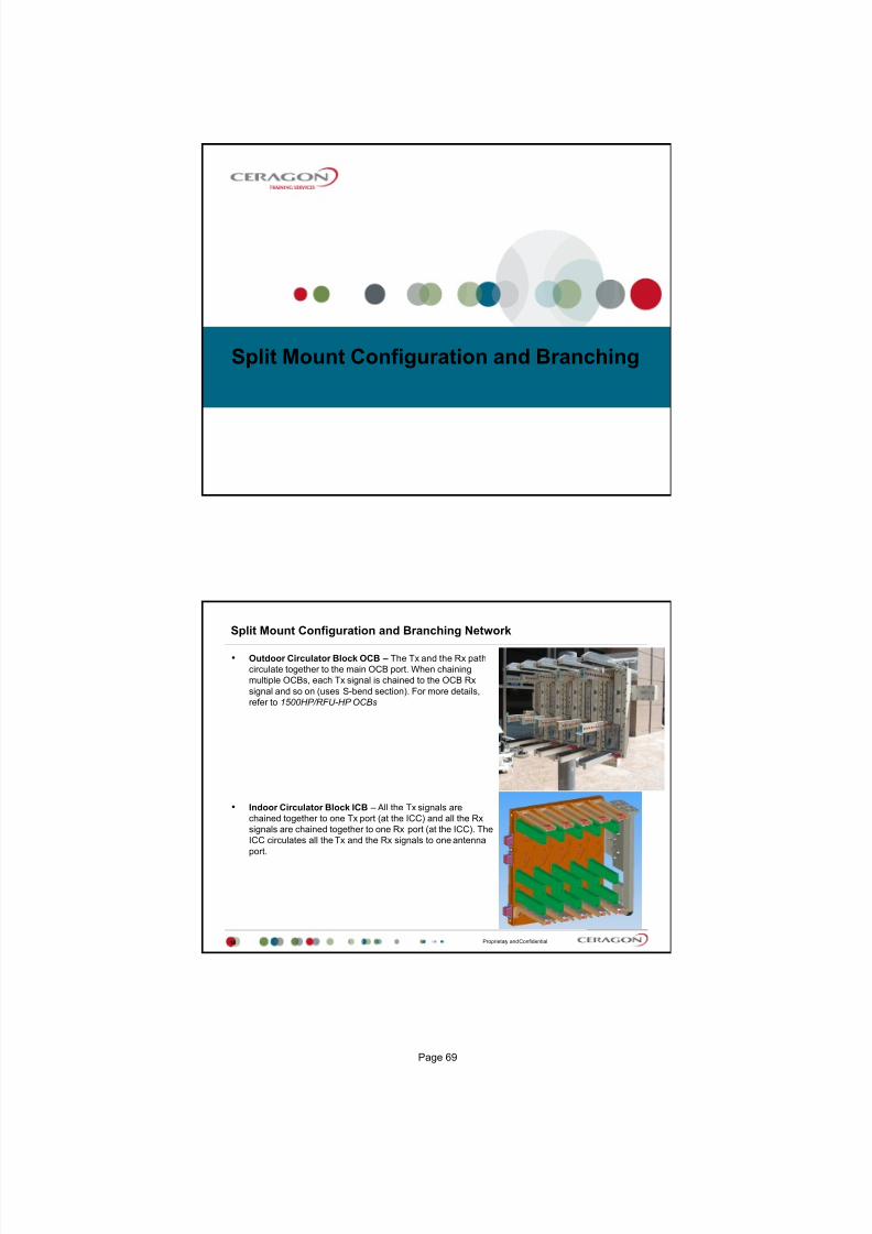
Outdoor Circulator Block OCB The Tx and the Rx path
circulate together to the main OCB port. When chaining
multiple OCBs, each Tx signal is chained to the OCB Rx
signal and so on (uses S-bend section). For more details,
refer to 1500HP/RFU-HP OCBs
Indoor Circulator Block ICB All the Tx signals are
chained together to one Tx port (at the ICC) and all the Rx
signals are chained together to one Rx port (at the ICC). The
ICC circulates all the Tx and the Rx signals to one antenna
port.
Page 69

7/25/2019 Handbook - FibeAir IP-20G Advanced Training Course T8.0 ver1.pdf
http://slidepdf.com/reader/full/handbook-fibeair-ip-20g-advanced-training-course-t80-ver1pdf 67/277
Proprietary and Confidential19
Split Mount Configuration and Branching Network
All- Indoor Vertical Branching Split-Mount Branching and All Indoor Compact
New OCB
20
Page 70

7/25/2019 Handbook - FibeAir IP-20G Advanced Training Course T8.0 ver1.pdf
http://slidepdf.com/reader/full/handbook-fibeair-ip-20g-advanced-training-course-t80-ver1pdf 68/277
Proprietary and Confidential21
New OCB Outdoor Circulator Block
The OCB has the following main purposes:
1. Hosts the circulators and the attached filters.
2. Chain and accumulate radio signal ( multiple carriers )
3. Routes the RF through the filters and circulators.
4. Allows RFU connection to the Main and Diversity antennas.
Proprietary and Confidential
New OCB Components
22
RF Filters - are used for specific frequency channels and Tx/Rx separation. The filters are attached to the OCB,
and each RFU contains one Rx and one Tx filter. In a Space Diversity using IF combining configuration, each RFU
contains two Rx filters (which combine the IF signals) and one Tx filter. The filters can be replaced without
removing the OCB. The RF filter is installed with every configuration.
DCB - Diversity Circulator Block An external block which is added in Space Diversity configurations. DCB is
connected to the diversity port and chains two OCBs.
Coupler Kit is used for 1+1 Hot Standby configurations. (loss 1.6 /6dB)
Symmetrical Coupler Kit is used for: (loss of 3/3 dB) When chaining adjacent channels (only 28/30 MHz) 1+1
Hot Standby configurations with a symmetrical loss of 3dB in each direction Note: CPLRs loss tolerance is ±0.7
dB
U Bend The U Bend connects the chained DCB (Diversity Circulator Block) in N+1/N+0 configurations.
S Bend The S Bend connects the chained OCB (Outdoor Circulator Block) in N+1/N+0 configurations.
Pole Mount Kit The Pole Mount Kit is used to fasten up to f ive OCBs and the RFUs to the pole. The kit enables
fast and easy installation.
Page 71

7/25/2019 Handbook - FibeAir IP-20G Advanced Training Course T8.0 ver1.pdf
http://slidepdf.com/reader/full/handbook-fibeair-ip-20g-advanced-training-course-t80-ver1pdf 69/277
Proprietary and Confidential
1+1 and 2+2 HSB Configuration
23
Proprietary and Confidential
N+0/N+1 Configuration
24
Page 72

7/25/2019 Handbook - FibeAir IP-20G Advanced Training Course T8.0 ver1.pdf
http://slidepdf.com/reader/full/handbook-fibeair-ip-20g-advanced-training-course-t80-ver1pdf 70/277
Proprietary and Confidential
2+0 XPIC
25
Proprietary and Confidential
Split mount applications
26
Page 73

7/25/2019 Handbook - FibeAir IP-20G Advanced Training Course T8.0 ver1.pdf
http://slidepdf.com/reader/full/handbook-fibeair-ip-20g-advanced-training-course-t80-ver1pdf 71/277
Proprietary and Confidential
Split mount applications 4+0
S-Bend
27
Proprietary and Confidential
Split mount applications 4+0 SD
S-Bend
U-Bend
DCB DCB
28
Page 74

7/25/2019 Handbook - FibeAir IP-20G Advanced Training Course T8.0 ver1.pdf
http://slidepdf.com/reader/full/handbook-fibeair-ip-20g-advanced-training-course-t80-ver1pdf 72/277
Thank You
Page 75

7/25/2019 Handbook - FibeAir IP-20G Advanced Training Course T8.0 ver1.pdf
http://slidepdf.com/reader/full/handbook-fibeair-ip-20g-advanced-training-course-t80-ver1pdf 73/277
Version 2
IP-20G Installation Guide
July 2015
Proprietary and Confidential
Agenda
2
Electromagnetic Fields, ESD and Laser Protection
General Requirements for Packing and Transportation and
Environment
IP-20G Rack Installation
Rack Installation
Grounding the IP-20G
Replacing SM-Card
Power Cable
Mechanical Specifications
Earth Bonding of Equipment
IP-20G to RFU-C connection Antenna Installation
RFU-C Installation
Page 77

7/25/2019 Handbook - FibeAir IP-20G Advanced Training Course T8.0 ver1.pdf
http://slidepdf.com/reader/full/handbook-fibeair-ip-20g-advanced-training-course-t80-ver1pdf 74/277
Proprietary and Confidential
High Frequency Electromagnetic Fields!
3
Exposure to strong high frequency electromagnetic fields may cause
thermal damage to personnel. The eye (cornea and lens) is easily exposed. Any unnecessary exposure is undesirable and should be avoided.
In radio-relay communication installations, ordinary setup for normaloperation, the general RF radiation level will be well below the safety limit.
In the antennas and directly in front of them the RF intensity normally willexceed the danger level, within limited portions of space.
Dangerous radiation may be found in the neighborhood of open waveguideflanges or horns where the power is radiated into space.
To avoid dangerous radiation the following precautions must be taken:
During work within and close to the front of the antenna; make sure thattransmitters will remain turned off.
Before opening coaxial - or waveguide connectors carrying RF power,turn off transmitters.
Consider any incidentally open RF connector as carrying power, untilotherwise proved. Do not look into coaxial connectors at closer than
reading distance (1 foot). Do not look into an open waveguide unlessyou are absolutely sure that the power is turned off.
Proprietary and Confidential
ESD & LASER
4
ESD
This equipment contains components which are sensitive to "ESD" (Electro
Static Discharge). Therefore, ESD protection measures must be observed
when touching the IDU.
Anyone responsible for the installation or maintenance of the FibeAir IDU
must use an ESD Wrist Strap.
Additional precautions include personnel grounding, grounding of work
bench, grounding of tools and instruments as well as transport and storage
in special antistatic bags and boxes.
LASER
Use of controls or adjustments or performance of procedures other than
those specified herein may result in hazardous radiation exposure.
The optical interface must only be serviced by qualified personnel, who areaware of the hazards involved to repair laser products.
Page 78
7/25/2019 Handbook - FibeAir IP-20G Advanced Training Course T8.0 ver1.pdf
http://slidepdf.com/reader/full/handbook-fibeair-ip-20g-advanced-training-course-t80-ver1pdf 75/277
General Requirements
Proprietary and Confidential
Transportation & Inspection
6
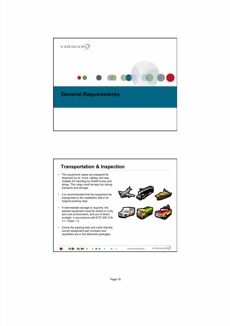
The equipment cases are prepared for
shipment by air, truck, railway and sea,
suitable for handling by forklift trucks and
slings. The cargo must be kept dry during
transport and storage.
It is recommended that the equipment be
transported to the installation site in its
original packing case.
If intermediate storage is required, the
packed equipment must be stored in a dry
and cool environment, and out of direct
sunlight, in accordance with ETS 300 019-
1-1, Class 1.2.
Check the packing lists and verify that the
correct equipment part numbers and
quantities are in the delivered packages.
Page 79

7/25/2019 Handbook - FibeAir IP-20G Advanced Training Course T8.0 ver1.pdf
http://slidepdf.com/reader/full/handbook-fibeair-ip-20g-advanced-training-course-t80-ver1pdf 76/277
Proprietary and Confidential
Packing & Transportation
7
The equipment is packed at the factory, and sealed moisture-absorbing bags
are inserted.
The equipment is prepared for public transportation. The cargo must be kept dry
during transportation.
Keep items in their original boxes till they reach their final destination.
If intermediate storage is required, the packed equipment must be stored in dry
and cool conditions and out of direct sunlight
When unpacking
Check the packing lists, and ensure that the
correct part numbers and quantities of
components arrived.
Proprietary and Confidential
General Requirements
8
1. Environmental specification for IDU: -5C (23F) to +55C (131F)
2. Environmental specification for RFU: -33C (-27F) to +55C (131F) high reliability
3. -45C (-49F) to +60C (140F) with limited margins
4. Cold startup requires at least -5C (23F)
5. Humidity: 5%RH to 95%RH for IP-20G
6. Humidity: 5%RH to 100%RH for RFU-C
7. IDU standard Input is -48VDC (-40 to -60VDC)
8. This equipment is designed to permit connection between the earthed conductor of
the DC supply circuit and the Earthing conductor at the equipment.
9. The equipment shall be connected to a properly grounded supply system
10. The DC supply system is to be local, i.e. within the same premises as the equipment
11. A disconnect device is not allowed in the grounded circuit between the DC supply
source and the frame/grounded circuit connection.
8
Page 80

7/25/2019 Handbook - FibeAir IP-20G Advanced Training Course T8.0 ver1.pdf
http://slidepdf.com/reader/full/handbook-fibeair-ip-20g-advanced-training-course-t80-ver1pdf 77/277
IP-20G Rack Installation
Proprietary and Confidential
Installing the IP-20G IDU
10
Kits required to perform the installation:
IP-20G chassis 1x
19 rack/ sub rack 1x
SM-Card Cover 1x
Tools:
Philips screwdriver
Flat screwdriver
Page 81

7/25/2019 Handbook - FibeAir IP-20G Advanced Training Course T8.0 ver1.pdf
http://slidepdf.com/reader/full/handbook-fibeair-ip-20g-advanced-training-course-t80-ver1pdf 78/277
Proprietary and Confidential
Rack Installation
11
Insert and hold the IP-20G IDU in the rack, as shown in the following
figures. Use four screws (not supplied with the installation kit) to fasten the
IDU to the rack.
Proprietary and Confidential
Grounding the IP-20G
12
Connect a grounding wire first to the single-point stud shown in the figure
below, and then to the rack, using a single screw and two washers.
The grounding wire must be 16 AWG or thicker
Page 82

7/25/2019 Handbook - FibeAir IP-20G Advanced Training Course T8.0 ver1.pdf
http://slidepdf.com/reader/full/handbook-fibeair-ip-20g-advanced-training-course-t80-ver1pdf 79/277
Proprietary and Confidential
Replacing an IP-20G IDU or SM-Card
13
If you should need to replace the IP-20G IDU, you must first remove the SM-Card Cover so that
you can insert it into the new IDU. The SM-Card holds the configuration and software for the IDU. The SM-Card is embedded in the
SM-Card Cover, so re-using the existing SM-Card Cover is necessary to ensure that the units
software and configuration is maintained.
In some cases, you may need to replace the SM-Card itself in order to upgrade the un its
configuration.
To remove the SM-Card Cover:
1. Loosen the screws of the SM-Card Cover and remove it from the IDU.
Proprietary and Confidential
Replacing an IP-20G IDU or SM-Card
14
2. In the new IDU or, if you are upgrading the SM-Card, the old IDU, make sure that there is no
foreign matter blocking the sockets in the opening where the SM-Card is installed.
3. Gently place the SM-Card Cover in its place and tighten the screws, using a Phillips screwdriver.
Page 83

7/25/2019 Handbook - FibeAir IP-20G Advanced Training Course T8.0 ver1.pdf
http://slidepdf.com/reader/full/handbook-fibeair-ip-20g-advanced-training-course-t80-ver1pdf 80/277
Proprietary and Confidential
Power Requirements
15
When selecting a power source, the following must be considered:
DC power can be from -40 VDC to -60 VDC.
Installation Codes: The equipment must be installed according to country national
electrical codes. For North America, equipment must be installed in accordance to the
US National Electrical Code, Articles 110-16, 110-17 and 110-18, and the Canadian
Electrical Code, Section 12.
Overcurrent Protection: A readily accessible listed branch circuit overcurrent
protective device, rated 15 A, must be incorporated in the building wiring.
Grounded Supply System: The equipment shall be connected to a properly grounded
supply system. All equipment in the immediate vicinity shall be grounded the same
way, and shall not be grounded elsewhere.
Local Supply System: The DC supply system is to be local, i.e. within the same
premises as the equipment.
Disconnect Device: A disconnect device is not allowed in the grounded circuit
between the DC supply source and the frame/grounded circuit connection.
15
Proprietary and Confidential
Power Interface
16
FibeAir IP-20G receives an external supply of -48V current via one or
two power interfaces (the second power interface is optional for power
redundancy). The IP-20G monitors the power supply for under-voltage
and includes reverse polarity protection, so that if the positive (+) and
negative (-) inputs are mixed up, the system remains shutdown.
The allowed power input range for the IP-20G is -40V to -60V. An under
voltage alarm is triggered if the power goes below the allowed range,
and an over voltage alarm is triggered if the power goes above the
allowed range.
Make sure to use a circuit breaker to protect the circuit from damage
by short or overload. In a building installation, the circuit breaker shall
be readily accessible and incorporated external to the equipment. The
maximum rating of the overcurrent protection shall be 10 Amp, while
the maximum current rating is 5 Amp.
Page 84

7/25/2019 Handbook - FibeAir IP-20G Advanced Training Course T8.0 ver1.pdf
http://slidepdf.com/reader/full/handbook-fibeair-ip-20g-advanced-training-course-t80-ver1pdf 81/277
Proprietary and Confidential
Power Cable
17
Proprietary and Confidential
Power cables
18
Page 85

7/25/2019 Handbook - FibeAir IP-20G Advanced Training Course T8.0 ver1.pdf
http://slidepdf.com/reader/full/handbook-fibeair-ip-20g-advanced-training-course-t80-ver1pdf 82/277
Proprietary and Confidential
Mechanical Specifications
19
Copyright © 2009 2013 Nera Networks AS All rights reserved. I-79113-EN rev. A
Earth Bonding of Equipment
Page 86

7/25/2019 Handbook - FibeAir IP-20G Advanced Training Course T8.0 ver1.pdf
http://slidepdf.com/reader/full/handbook-fibeair-ip-20g-advanced-training-course-t80-ver1pdf 83/277
Proprietary and Confidential21
Note 1: Structure or cable riser directly connected to StationEarth Network.
Note 2: Main Earth Bar in equipment room, connected toStation Earth Network.
Note 3: Earth Bus Bar/Cable connected to main earth bar.
Note 4: Coax Signal Cable.
Note 5: Over voltage protection integrated in units.
Note 1
Typical Earthing Network
Proprietary and Confidential
There are three logical positions where
a Waveguide/Feeder Earthing Kit should be installed:
1. Highest priority is at the bottom of the vertical
feeder run, on the straight section just above the
bend where it transitions from vertical to
horizontal.
2. Jumper Leads from the kit should be bonded to
the Tower Structure:
- directly (bolted connection)
- via a earth termination plate (if provided)
- stainless steel angle adaptor (ANDREW)
3. Earth Kit on the feeder should be positioned
so that each jumper lead has a uniform smooth
transition down to the point of bonding this may
mean staggering their position as shown here.
4. It is preferred that each jumper is bonded
separately.
SEE NEXT TWO SLIDES
Jumper lead between Earthing Kit
and buried earth radial bonded to baseof the Tower Leg.
Recommended 70mm² PVC Coated Conductor
Earthing Kit staggered to ensure smooth,
uniform jumper transition to point of bonding.
Custom Earthing Kit supplied from the
Feeder Manufacturer use only kit that are
compatible.
Never intermix components from different
Manufacturers.
Ceragon Networks provides one
Earthing kit per feeder as standard
Feeder - Earthing Kit (pos.1)
22
Page 87

7/25/2019 Handbook - FibeAir IP-20G Advanced Training Course T8.0 ver1.pdf
http://slidepdf.com/reader/full/handbook-fibeair-ip-20g-advanced-training-course-t80-ver1pdf 84/277
Proprietary and Confidential
The second position in order of priority is just before the
waveguide/feeder enters the shelter through the wall plate.
1. Again it is important that the jumper lead forms a smooth
transition downwards to earth. In this case the bonding
point is on the earth termination plate mounted below the
cable bridge.
2. It is preferred that each jumper is bonded separately. Earth
Termination Plate usually have multiple bonding holes pre-
drilled.
3. To shape each conductor correctly begin at the earth
termination plate and form the cable to the best transition
back to the feeder. From there you will establish the
location to fit the earth kit. Treat each earthing kit
separately.
Common ErrorsFitting or, finding the Earth Termination Plate too high on the
shelter wall often prevent achieving the required earth
jumper transition.
Second line of defence
Jumper lead between Earthing Kit
and Earth Termination Plate outside
shelter.Recommended 70mm² PVC Coated
Conductor or 3mm x 25mm CopperTape.
Conductor / Tape should be run outto the
Buried earth loop at a depth of600mm.
Earth Kit
Earth Termination Plate
Feeder - Earthing Kit (pos.2)
23
Proprietary and Confidential
The third position in order of priority is at the antenna position.
Here, the Earthing Kit is fitted on the vertical straight
section of feeder just after the transition from horizontal to
vertical.
1. Once again it is important that the jumper lead forms a
smooth transition downwards to earth. It is usual to use thetower structure itself as the main down conductor.
2. To shape each conductor correctly begin at the bonding
point and form the cable to the best transition back to the
feeder. From there you will establish the best position to fit
the earth kit to the feeder. Treat each earthing kit
separately.
3. If using a Stainless Steel Angle Adaptor this will provide
flexibility to establishing a bonding point on the tower the
Angle Adaptor does not require you to find or drill a hole inany structural members.
The tower structure orclimbing ladder are
both commonly used
for bonding the earth jumper.
Angle Adaptors are the
most convenient
bonding method as thisavoids finding or
drilling holes at heightin the tower.
Additional Earthing Kit:
If a customer specifies additional earthing kit to be fitted, these
would normally be positioned between the two kit installed at thetop and bottom of the feeder.
Feeder - Earthing Kit (pos.3)
24
Page 88

7/25/2019 Handbook - FibeAir IP-20G Advanced Training Course T8.0 ver1.pdf
http://slidepdf.com/reader/full/handbook-fibeair-ip-20g-advanced-training-course-t80-ver1pdf 85/277
Proprietary and Confidential
RSSI
EARTH TERMINAL
N-Type to IDU connection
4. BOND TO TOWER STRUCTURE.CLAMP TYPE DEPENDENT ONTOWER MEMBER PROFILE
3. SUPPORT EARTH JUMPERWHERE NEEDED
1. SMOOTH JUMPER TRANSITION
2. SHORTEN THE JUMPER IF TOO LONG
EACH ODU IS SEPARATELYEARTHED DO NOT JUMPER
BETWEEN ODU
ODU Earthing
25
Proprietary and Confidential
With All Cable Installations
Avoid leaving coils along
feeder cables
Avoid kinking the cable
Avoid cable loopbacks
Applying the same principles to all cables
26
Page 89

7/25/2019 Handbook - FibeAir IP-20G Advanced Training Course T8.0 ver1.pdf
http://slidepdf.com/reader/full/handbook-fibeair-ip-20g-advanced-training-course-t80-ver1pdf 86/277
Proprietary and Confidential
Weatherproofing
Each Earthing Kit should be protected with a waterproof weather seal
If the weather seals are not provided as part of the main Earthing Kit, they must be
ordered
Each kit is provided with an installation instruction (or, Bulletin)
Always follow the advice given in the instruction to achieve the best possible
installation
27
ODU to IDU connection
Page 90

7/25/2019 Handbook - FibeAir IP-20G Advanced Training Course T8.0 ver1.pdf
http://slidepdf.com/reader/full/handbook-fibeair-ip-20g-advanced-training-course-t80-ver1pdf 87/277
Proprietary and Confidential
IP-20G to RFU-C connection
29
TNC females
N-type female
TNC
The cable should have a maximum attenuation of 30 dB at 350 MHz.
N-type male
TNC male
Proprietary and Confidential
N-type connector installation
30
http://www.youtube.com/watch
?v=cAV_xhP3FNA
http://www.youtube.com/watch
?v=Mo9LwdHe39M
Page 91
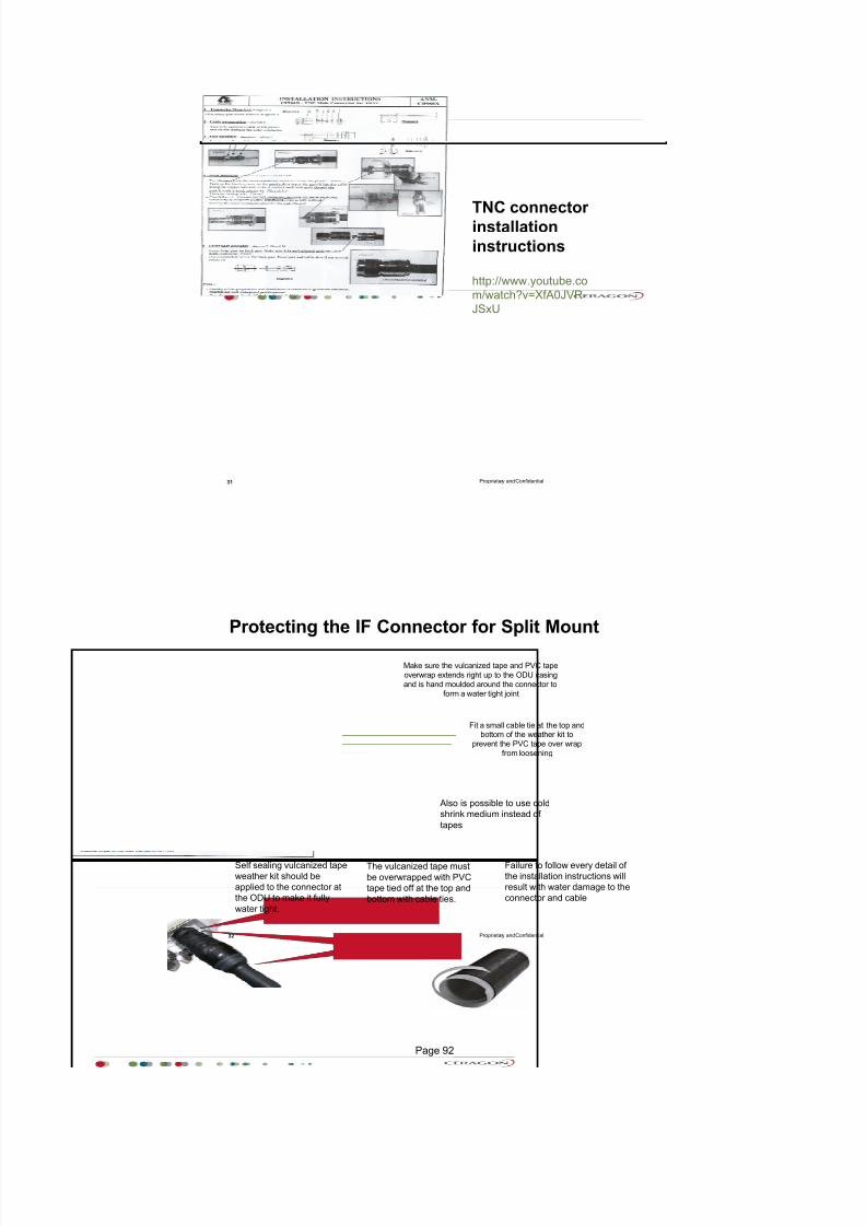
7/25/2019 Handbook - FibeAir IP-20G Advanced Training Course T8.0 ver1.pdf
http://slidepdf.com/reader/full/handbook-fibeair-ip-20g-advanced-training-course-t80-ver1pdf 88/277
Proprietary and Confidential
TNC connectorinstallation
instructions
31
http://www.youtube.co
m/watch?v=XfA0JVR
JSxU
Proprietary and Confidential
Self sealing vulcanized tape
weather kit should be
applied to the connector at
the ODU to make it fully
water tight.
Make sure the vulcanized tape and PVC tape
overwrap extends right up to the ODU casing
and is hand moulded around the connector to
form a water tight joint
Fit a small cable tie at the top andbottom of the weather kit to
prevent the PVC tape over wrap
from loosening
Failure to follow every detail of
the installation instructions will
result with water damage to the
connector and cable
The vulcanized tape must
be overwrapped with PVC
tape tied off at the top and
bottom with cable ties.
Also is possible to use cold
shrink medium instead of
tapes
32
Protecting the IF Connector for Split Mount
Page 92

7/25/2019 Handbook - FibeAir IP-20G Advanced Training Course T8.0 ver1.pdf
http://slidepdf.com/reader/full/handbook-fibeair-ip-20g-advanced-training-course-t80-ver1pdf 89/277
Proprietary and Confidential
When securing cables with cable
ties the method shown here can
normally be achieved using a single
tie.This method will keep the cablestraight and provide the best
support
Avoid this method which isless secure and will cause
unsightly bending of the
cable
Tower Cross Member
IF Cable
33
Cable Clamping
Proprietary and Confidential
Cable Installation and Grounding
34
For optical cables no grounding is required
For Ethernet cables, the cable should be grounded to the antenna tower
every 50m using the kit CAT5E_gnd_kit.
Procedure see installation Guide
Page 93

7/25/2019 Handbook - FibeAir IP-20G Advanced Training Course T8.0 ver1.pdf
http://slidepdf.com/reader/full/handbook-fibeair-ip-20g-advanced-training-course-t80-ver1pdf 90/277
Antenna Installation
Proprietary and Confidential
1,9V
1,6V
1,3V
-30dBm -60dbm -90dBm
RSSI Curve
36
Page 94

7/25/2019 Handbook - FibeAir IP-20G Advanced Training Course T8.0 ver1.pdf
http://slidepdf.com/reader/full/handbook-fibeair-ip-20g-advanced-training-course-t80-ver1pdf 91/277
Proprietary and Confidential
Receiving AntennaSIDE LOBE
SIDE LOBE
MAIN BEAM
AZ I M UT H
Important to establish which are the side lobes
and what is the main beam
Position can be marked onto the column or
interface using a felt tipped pen
For Azimuth panning it is important to establish the
strongest possible signal but remember, further improvement
should be expected once elevation adjustment is carried out
Always Pan antenna
beyond each side lobe
37
Antenna Panning - Azimuth
Proprietary and Confidential
SIDE LOBE
SIDE LOBE
MAIN BEAM
E L E V AT I ON
HORIZONTAL
Determine from available data if the antenna direction
of shoot is above or below horizontal to ensure the
elevation is adjusted in the correct direction
With the main beam having already been established
it is not necessary to find the side lobes again
Once the best signal strength has been found using
elevation minor azimuth panning can oftenimprove the signal strength further
Receiving Antenna
Note:
It should not always be expected to establish the strongest receive signal at
first attempt to align an antenna
Antenna may need to be panned several times before the optimum signal
strength is established
38
Antenna Panning - Elevation
Page 95
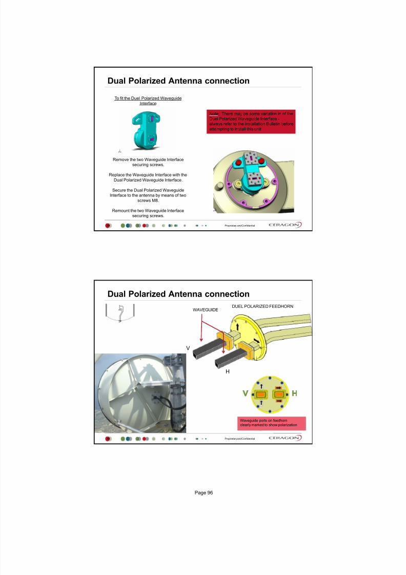
7/25/2019 Handbook - FibeAir IP-20G Advanced Training Course T8.0 ver1.pdf
http://slidepdf.com/reader/full/handbook-fibeair-ip-20g-advanced-training-course-t80-ver1pdf 92/277
Proprietary and Confidential
Dual Polarized Antenna connection
To fit the Duel Polarized WaveguideInterface
Remove the two Waveguide Interface
securing screws.
Replace the Waveguide Interface with the
Dual Polarized Waveguide Interface.
Secure the Dual Polarized Waveguide
Interface to the antenna by means of twoscrews M8.
Remount the two Waveguide Interface
securing screws.
Note: There may be some variation in of the
Duel Polarized Waveguide Interface -
always refer to the installation Bulletin before
attempting to install this unit
39
Proprietary and Confidential
Dual Polarized Antenna connectionWAVEGUIDE
Waveguide ports on feedhorn
clearly marked to show polarization
DUEL POLARIZED FEEDHORN
V
H
40
Page 96

7/25/2019 Handbook - FibeAir IP-20G Advanced Training Course T8.0 ver1.pdf
http://slidepdf.com/reader/full/handbook-fibeair-ip-20g-advanced-training-course-t80-ver1pdf 93/277
RFU-C Installation
Proprietary and Confidential
RFU-C waveguide flanges
42
Page 97

7/25/2019 Handbook - FibeAir IP-20G Advanced Training Course T8.0 ver1.pdf
http://slidepdf.com/reader/full/handbook-fibeair-ip-20g-advanced-training-course-t80-ver1pdf 94/277
Proprietary and Confidential
RFU-C direct mount configurations
1+0 direct
43
Proprietary and Confidential
RFU-C and Antenna Interface Direct Mount Polarization
44
Page 98

7/25/2019 Handbook - FibeAir IP-20G Advanced Training Course T8.0 ver1.pdf
http://slidepdf.com/reader/full/handbook-fibeair-ip-20g-advanced-training-course-t80-ver1pdf 95/277
Proprietary and Confidential
1+0 remote
45
RFU-C remote mount configurations
Proprietary and Confidential
RFU-C direct 1+1 mount configurations
1+1 direct
46
Page 99

7/25/2019 Handbook - FibeAir IP-20G Advanced Training Course T8.0 ver1.pdf
http://slidepdf.com/reader/full/handbook-fibeair-ip-20g-advanced-training-course-t80-ver1pdf 96/277
Proprietary and Confidential
RFU-C 1+1 Coupler Direct Mount Polarization
47
Vertical Polarization Horizontal Polarization
Proprietary and Confidential
RFU-C remote mount configurations
1+1 remote
48
Page 100

7/25/2019 Handbook - FibeAir IP-20G Advanced Training Course T8.0 ver1.pdf
http://slidepdf.com/reader/full/handbook-fibeair-ip-20g-advanced-training-course-t80-ver1pdf 97/277
Proprietary and Confidential
Orthogonal Mode Transducer (OMT) Installation
49
Switch to the circular adaptor
(removing the
existing rectangular transition,
swapping the O-ring, and
replacing on the circular
transition).
Proprietary and Confidential
OMT Installation Example
50
Page 101
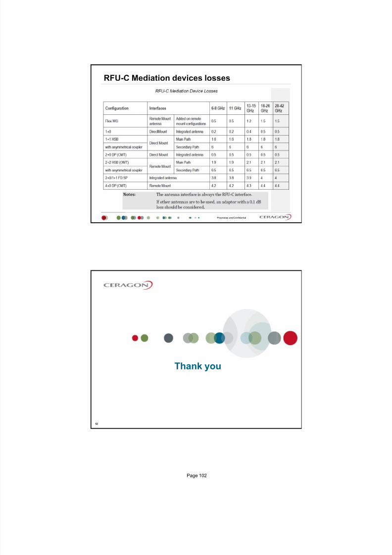
7/25/2019 Handbook - FibeAir IP-20G Advanced Training Course T8.0 ver1.pdf
http://slidepdf.com/reader/full/handbook-fibeair-ip-20g-advanced-training-course-t80-ver1pdf 98/277
Proprietary and Confidential
RFU-C Mediation devices losses
51
Thank you
52
Page 102

7/25/2019 Handbook - FibeAir IP-20G Advanced Training Course T8.0 ver1.pdf
http://slidepdf.com/reader/full/handbook-fibeair-ip-20g-advanced-training-course-t80-ver1pdf 99/277
July 2015, v4
First login
Ceragon Training Services
Proprietary and Confidential
Agenda
2
CLI and Web login
General commands
Get IP address
Set IP address
Set to default
Web Management
Page 103

7/25/2019 Handbook - FibeAir IP-20G Advanced Training Course T8.0 ver1.pdf
http://slidepdf.com/reader/full/handbook-fibeair-ip-20g-advanced-training-course-t80-ver1pdf 100/277
Proprietary and Confidential
Connecting to the Unit
3
CLI via Serial
Web/Telnet
Default Username/password is admin/admin
Baud rate =
115200
Bits per Second 115,200
DataBits 8
Parity None
Stop Bits 1
Flow Control - NoneIP address = 192.168.1.1
Proprietary and Confidential
General commands
4
Press twice the TAB key for optional commands in actual directoryUse the TAB key to auto-complete a syntax
Use the arrow keys to navigate through recent commands
Question mark to list helpful commands
Page 104

7/25/2019 Handbook - FibeAir IP-20G Advanced Training Course T8.0 ver1.pdf
http://slidepdf.com/reader/full/handbook-fibeair-ip-20g-advanced-training-course-t80-ver1pdf 101/277
Proprietary and Confidential
Get IP address
5
CLI Command:
platform management ip show ip-address
Proprietary and Confidential
Changing Management IP Address
6
CLI Command:
platform management ip set ipv4-address <IP Address> subnet <Mask >
gateway <default gateway >
Example
Web
expand Platform branch, then Management branch and click on IP, set
accordingly and click Apply button
Page 105

7/25/2019 Handbook - FibeAir IP-20G Advanced Training Course T8.0 ver1.pdf
http://slidepdf.com/reader/full/handbook-fibeair-ip-20g-advanced-training-course-t80-ver1pdf 102/277
Proprietary and Confidential
Set to default
7
CLI Command:
platform management set-to-default
Please note that IP address after Set to Factory Default will be not changed!!!
Proprietary and Confidential
Other CLI commands
8
For any CLI commands please follow our Web Manual
Open Index html file
Find out in Topics submenu required configuration
Page 106

7/25/2019 Handbook - FibeAir IP-20G Advanced Training Course T8.0 ver1.pdf
http://slidepdf.com/reader/full/handbook-fibeair-ip-20g-advanced-training-course-t80-ver1pdf 103/277
Proprietary and Confidential
Ethernet Management Interface IP-20G
9
FibeAir IP-20G contains two FE management interfaces, which connect to a single RJ-45 physical
connector on the front panel (MGMT).
If the user only needs to use a single management interface, a standard Cat5 RJ-45 cable (straight or
cross) can be connected to the MGMT interface.
To access both management interfaces, a special 2 x FE splitter cable can be ordered from Ceragon.
Port Status LED The LED for management interface 1 is located on the upper left of the MGMT
interface. The LED for management interface 2 is located on the upper right of the MGMT interface.
Proprietary and Confidential
Enable Second MNG port via Splitter
10
CH2 used for the same MNG IP address
CH1
CH2
Page 107

7/25/2019 Handbook - FibeAir IP-20G Advanced Training Course T8.0 ver1.pdf
http://slidepdf.com/reader/full/handbook-fibeair-ip-20g-advanced-training-course-t80-ver1pdf 104/277
Proprietary and Confidential
Enable Second MNG port via Splitter
11
Web Management
12
Page 108

7/25/2019 Handbook - FibeAir IP-20G Advanced Training Course T8.0 ver1.pdf
http://slidepdf.com/reader/full/handbook-fibeair-ip-20g-advanced-training-course-t80-ver1pdf 105/277
Proprietary and Confidential
First Web login
13
Default IP address is 192.168.1.1 /24
Default Username/password is admin/admin
Proprietary and Confidential
Main View
14
Menu
Finding topic
Picture of
managed
element
Page 109

7/25/2019 Handbook - FibeAir IP-20G Advanced Training Course T8.0 ver1.pdf
http://slidepdf.com/reader/full/handbook-fibeair-ip-20g-advanced-training-course-t80-ver1pdf 106/277
Proprietary and Confidential
Platform / Management / Unit Parameters
15
Proprietary and Confidential
Platform / Management / NTP Configuration
16
Page 110

7/25/2019 Handbook - FibeAir IP-20G Advanced Training Course T8.0 ver1.pdf
http://slidepdf.com/reader/full/handbook-fibeair-ip-20g-advanced-training-course-t80-ver1pdf 107/277
Proprietary and Confidential
Platform / Management / Time Services
17
Proprietary and Confidential
Platform / Management / Interface Manager
18
Default status is
! DOWN ! Managing of all ports
Page 111
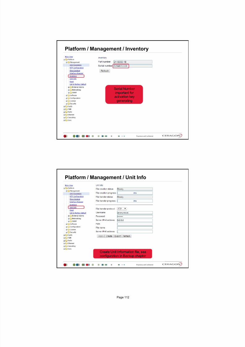
7/25/2019 Handbook - FibeAir IP-20G Advanced Training Course T8.0 ver1.pdf
http://slidepdf.com/reader/full/handbook-fibeair-ip-20g-advanced-training-course-t80-ver1pdf 108/277
Proprietary and Confidential
Platform / Management / Inventory
19
Serial Number
important for
activation key
generating
Proprietary and Confidential
Platform / Management / Unit Info
20
Create Unit Information file, see
configuration in Backup chapter
Page 112

7/25/2019 Handbook - FibeAir IP-20G Advanced Training Course T8.0 ver1.pdf
http://slidepdf.com/reader/full/handbook-fibeair-ip-20g-advanced-training-course-t80-ver1pdf 109/277
Proprietary and Confidential
Platform / Management / Reset
21
Provide software reboot
Proprietary and Confidential
Platform / Management / Set to Factory Default
22
Clear configuration database
Page 113

7/25/2019 Handbook - FibeAir IP-20G Advanced Training Course T8.0 ver1.pdf
http://slidepdf.com/reader/full/handbook-fibeair-ip-20g-advanced-training-course-t80-ver1pdf 110/277
Proprietary and Confidential
IP address settings
23
Proprietary and Confidential
SNMP Parameters
24
Setting for NMS system
Page 114

7/25/2019 Handbook - FibeAir IP-20G Advanced Training Course T8.0 ver1.pdf
http://slidepdf.com/reader/full/handbook-fibeair-ip-20g-advanced-training-course-t80-ver1pdf 111/277
Proprietary and Confidential
Trap Managers
25
Up to 4 Trap Managers
Proprietary and Confidential
V3 User
26
Setting for SNMP v3
Page 115

7/25/2019 Handbook - FibeAir IP-20G Advanced Training Course T8.0 ver1.pdf
http://slidepdf.com/reader/full/handbook-fibeair-ip-20g-advanced-training-course-t80-ver1pdf 112/277
Thank You
Page 116

7/25/2019 Handbook - FibeAir IP-20G Advanced Training Course T8.0 ver1.pdf
http://slidepdf.com/reader/full/handbook-fibeair-ip-20g-advanced-training-course-t80-ver1pdf 113/277
July 2015, version 4
Radio Link Parameters
Ceragon Training Services
Proprietary and Confidential
Agenda
2
MRMC
TX & RX Frequencies
Link ID
RSL
MSE
Current ACM Profile
Page 117

7/25/2019 Handbook - FibeAir IP-20G Advanced Training Course T8.0 ver1.pdf
http://slidepdf.com/reader/full/handbook-fibeair-ip-20g-advanced-training-course-t80-ver1pdf 114/277
Proprietary and Confidential
High and Low frequency station
Local site
High station
Remote site
Low station
High station means: Tx(f1) >Rx(f1)
Tx(f1)=11500 MHz Rx(f1)=11500 MHz
Rx(f1)=11000 MHz Tx(f1)=11000 MHz
Low station means: Tx(f1) < Rx(f1)
Full duplex
3
Proprietary and Confidential
IDU ODU IDUODU) ))TSL RSL
Radio Link Parameters
4
To Establish a radio link, we need configure following parameters:
1. MRMC Modem scripts (ACM or fixed capacity, channel & modulation)
2. TX / RX frequencies set on every radio
3. Link ID must be the same on both ends
4. Max. TSL Max. allowed Transmission Signal [dBm]
5. Unmute Transceiver Transceiver is by default muted (is not transmitting)
-------------------------------------------------------------------------------------------------------
To verify a radio link, we need control following parameters:1. RSL Received Signal Level [dBm] nominal input level is required
2. MSE- Mean Square Error [dB]
3. Current ACM profile
Page 118

7/25/2019 Handbook - FibeAir IP-20G Advanced Training Course T8.0 ver1.pdf
http://slidepdf.com/reader/full/handbook-fibeair-ip-20g-advanced-training-course-t80-ver1pdf 115/277
Proprietary and Confidential
Modulation RFU‐C RFU
‐C Premium
QPSK Profile 0 Profile 0
8QAM Profile 1 Profile 1
16QAM Profile 2 Profile 2
32QAM Profile 3 Profile 3
64QAM Profile 4 Profile 4
128QAM Profile 5 Profile 5
256QAM (strong FEC) Profile 6 N/A
256QAM (weak FEC) Profile 7 Profile 6
512QAM N/A Profile 7
1024QAM (Strong FEC) N/A Profile 8
1024QAM (Light FEC) N/A Profile9
MRMC Multi Rate Multi Coding Profiles
5
Proprietary and Confidential
MRMC Scripts 1st
steep
6
Changing script automatically resets modem inside IP‐20G
Page 119

7/25/2019 Handbook - FibeAir IP-20G Advanced Training Course T8.0 ver1.pdf
http://slidepdf.com/reader/full/handbook-fibeair-ip-20g-advanced-training-course-t80-ver1pdf 116/277
Proprietary and Confidential
Radio Parameters settings
7
2nd step
3th step
4th step
5th step
Proprietary and Confidential
To avoid pointing the antenna to a wrong direction (when both links share the same
frequency), LINK ID can be used to alert when such action is take.
Link ID Mismatch
# 101
# 101
# 101
# 102Link ID
Mismatch
LINK ID Antenna Alignment Process
8
Page 120

7/25/2019 Handbook - FibeAir IP-20G Advanced Training Course T8.0 ver1.pdf
http://slidepdf.com/reader/full/handbook-fibeair-ip-20g-advanced-training-course-t80-ver1pdf 117/277
Proprietary and Confidential
Both IDUs of the same link must use the same Link IDOtherwise, Link ID Mismatch alarm will appear in Current Alarms Window
Link ID Mismatch
# 101
# 101
# 101
# 102Link ID
Mismatch
LINK ID Antenna Alignment Process
9
Proprietary and Confidential
Questions?
10
Page 121

7/25/2019 Handbook - FibeAir IP-20G Advanced Training Course T8.0 ver1.pdf
http://slidepdf.com/reader/full/handbook-fibeair-ip-20g-advanced-training-course-t80-ver1pdf 118/277
Proprietary and Confidential
Radio Link Setup Exercise
11
Thank You
Page 122

7/25/2019 Handbook - FibeAir IP-20G Advanced Training Course T8.0 ver1.pdf
http://slidepdf.com/reader/full/handbook-fibeair-ip-20g-advanced-training-course-t80-ver1pdf 119/277
July 2015, version 4
ACM Adaptive Coding and Modulation
MSE Mean Square Error
Ceragon Training Services
Proprietary and Confidential
Agenda
2
Adaptive Coding and Modulation
Using MSE with ACM
What is MSE?
Link Commissioning with MSE
Triggering ACM with MSE
Page 123

7/25/2019 Handbook - FibeAir IP-20G Advanced Training Course T8.0 ver1.pdf
http://slidepdf.com/reader/full/handbook-fibeair-ip-20g-advanced-training-course-t80-ver1pdf 120/277
Proprietary and Confidential
Adaptive Coding and Modulation (ACM)
3
In ACM mode, the radio will select the highest possible link capacity based on received signal quality.
When the signal quality is degraded due to link fading or interference, the radio will change to a more robust
modulation and link capacity is consequently reduced.
When signal quality improves, the modulation is automatically increased and link capacity is restored to the original
setting. The capacity changes are hitless (no bit errors introduced).
During the period of reduced capacity, the traffic is prioritized based on Ethernet QoS - and TDM priority - settings.
In case of congestion the Ethernet or TDM traffic with lowest priority is dropped. TDM capacity per modulation
state is configurable as part of the TDM priority setting.
H i g h P r i o r i t y
T r a f f i c
L o w P
r i o r i t y
T r a f f i c
1 0 2 4 Q A M
L F E C
1 0 2 4 Q A M
S F E C
5 1 2 Q A M
2 5 6 Q A M
1 2 8 Q A M
6 4 Q A M
3 2 Q A M
1 6 Q A M
8 Q A M
4 Q A M
2 0 4 8 Q A C M
Proprietary and Confidential
Hitless and Errorless switching
4
Page 124

7/25/2019 Handbook - FibeAir IP-20G Advanced Training Course T8.0 ver1.pdf
http://slidepdf.com/reader/full/handbook-fibeair-ip-20g-advanced-training-course-t80-ver1pdf 121/277
Using MSE with ACM
Proprietary and Confidential
MSE - Definition
6
MSE is used to quantify the difference between an estimated
(expected) value and the true value of the quantity being
estimated
MSE measures the average of the squared errors:
MSE is an aggregated error by which the expected value differs
from the quantity to be estimated.
The difference occurs because of randomness or because the
receiver does not account for information that could produce amore accurate estimated RSL
Page 125

7/25/2019 Handbook - FibeAir IP-20G Advanced Training Course T8.0 ver1.pdf
http://slidepdf.com/reader/full/handbook-fibeair-ip-20g-advanced-training-course-t80-ver1pdf 122/277
Proprietary and Confidential
To simplify.
7
Imagine a production line where a machine needs to insert
one part into the other
Both devices must perfectly match
Let us assume the width has to be 10mm wide
We took a few of parts and measured them to see how
many can fit in.
Proprietary and Confidential
The Errors Histogram(Gaussian probability distribution function)
8
To evaluate how accurate our machine is, we need to know how many
parts differ from the expected value
9 parts were perfectly OK
10mm 12mm 16mm6mm 7mm
width
Quantity
3
23
1
9 Expected value
Page 126
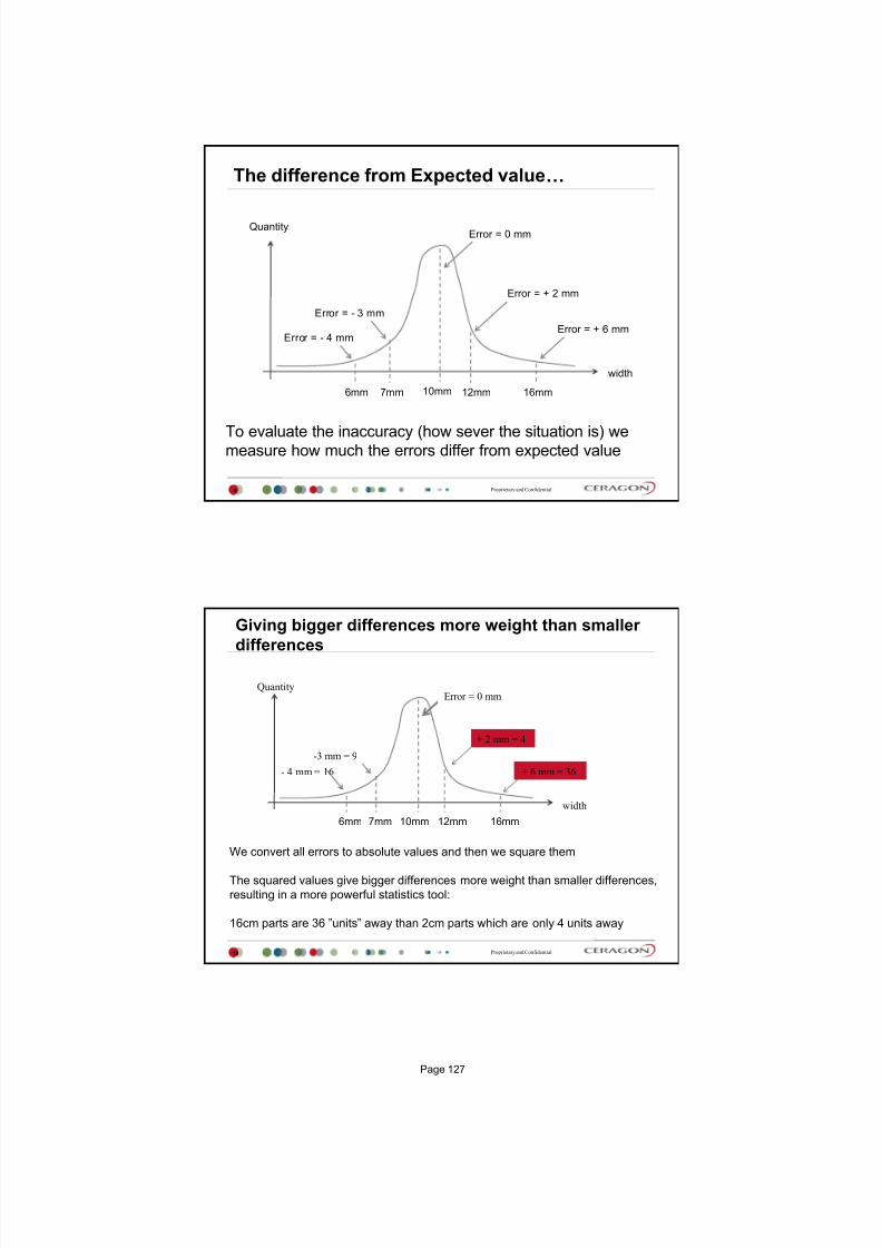
7/25/2019 Handbook - FibeAir IP-20G Advanced Training Course T8.0 ver1.pdf
http://slidepdf.com/reader/full/handbook-fibeair-ip-20g-advanced-training-course-t80-ver1pdf 123/277
Proprietary and Confidential
The difference from Expected value
9
To evaluate the inaccuracy (how sever the situation is) wemeasure how much the errors differ from expected value
10mm 12mm 16mm6mm 7mm
width
Quantity
Error = + 6 mm
Error = - 3 mm
Error = + 2 mm
Error = 0 mm
Error = - 4 mm
Proprietary and Confidential
Giving bigger differences more weight than smaller
differences
10
We convert all errors to absolute values and then we square them
The squared values give bigger differences more weight than smaller differences,
resulting in a more powerful statistics tool:
16cm parts are 36 units away than 2cm parts which are only 4 units away
10mm 12mm 16mm6mm 7mm
width
Quantity
+ 6 mm = 36
-3 mm = 9
+ 2 mm = 4
Error = 0 mm
- 4 mm = 16
Page 127
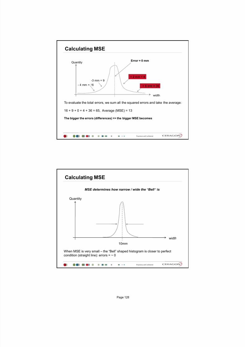
7/25/2019 Handbook - FibeAir IP-20G Advanced Training Course T8.0 ver1.pdf
http://slidepdf.com/reader/full/handbook-fibeair-ip-20g-advanced-training-course-t80-ver1pdf 124/277
Proprietary and Confidential
Calculating MSE
11
To evaluate the total errors, we sum all the squared errors and take the average:
16 + 9 + 0 + 4 + 36 = 65, Average (MSE) = 13
The bigger the errors (differences) >> the bigger MSE becomes
width
Quantity
+ 6 mm = 36
-3 mm = 9
+ 2 mm = 4
Error = 0 mm
- 4 mm = 16
Proprietary and Confidential
Calculating MSE
12
When MSE is very small the Bell shaped histogram is closer to perfect
condition (straight line): errors = ~ 0
10mm
width
Quantity
MSE determines how narrow / wide the Bell is
Page 128

7/25/2019 Handbook - FibeAir IP-20G Advanced Training Course T8.0 ver1.pdf
http://slidepdf.com/reader/full/handbook-fibeair-ip-20g-advanced-training-course-t80-ver1pdf 125/277
Proprietary and Confidential
MSE in digital modulation (Radios)
13
Let us use QPSK (4QAM)
as an example:
QPSK = 2 bits per symbol
2 possible states for I signal
2 possible states for Q signal
= 4 possible states for the
combined signal
The graph shows the expectedvalues (constellation) of the
received signal (RSL)
0001
1011
I
Q
Proprietary and Confidential
MSE in digital modulation (Radios)
14
The black dots represent the
expected values (constellation)
of the received signal (RSL)
The blue dots represent the
actual RSL
As indicated in the previous
example, we can say that the
bigger the errors are theharder it becomes for the
receiver to detect & recover the
transmitted signal
0001
1011
I
Q
Page 129

7/25/2019 Handbook - FibeAir IP-20G Advanced Training Course T8.0 ver1.pdf
http://slidepdf.com/reader/full/handbook-fibeair-ip-20g-advanced-training-course-t80-ver1pdf 126/277
Proprietary and Confidential
MSE in digital modulation (Radios)
15
MSE would be the average
errors of e1 + e2 + e3 + e4.
When MSE is very small the
actual signal is very close to
the expected signal
0001
1011
I
Q
e1
e2
e3e4
Proprietary and Confidential
MSE in digital modulation (Radios)
16
When MSE is too big, the
actual signal (amplitude &
phase) is too far from the
expected signal
0001
1011
I
Q
e1
e2
e3e4
Page 130

7/25/2019 Handbook - FibeAir IP-20G Advanced Training Course T8.0 ver1.pdf
http://slidepdf.com/reader/full/handbook-fibeair-ip-20g-advanced-training-course-t80-ver1pdf 127/277
Proprietary and Confidential
Commissioning with MSE in EMS
17
When you commission your
radio link, make sure your MSE
is small
Actual values may be read
-39dB to -41dB
Bigger values will result in loss
of signal
Proprietary and Confidential
MSE and ACM
18
When the errors is too big, we need
a stronger error correction
mechanism (FEC)
Therefore, we reduce the number
of bits per symbol allocated for data
and re-assign the extra bits for
correction instead
For example
256QAM has great capacity but
poor immune to noise
64QAM has less capacity but much
better immune for noise
ACM Adaptive Code Modulation
Page 131

7/25/2019 Handbook - FibeAir IP-20G Advanced Training Course T8.0 ver1.pdf
http://slidepdf.com/reader/full/handbook-fibeair-ip-20g-advanced-training-course-t80-ver1pdf 128/277
Proprietary and Confidential
Triggering ACM with MSE
19
When ACM is enabled, MSE values are analyzed on each side of the link
When MSE degrades or improves, the system applies the required
modulation per radio to maintain service
Profile Mod MSE Down-Threshold MSE Up-Threshold
0 QPSK -18
1 8PSK -16 -19
2 16QAM -17 -23
3 32QAM -21 -26
4 64QAM -24 -29
5 128QAM -27 -32
6 256QAM -30 -34
7 512QAM -32 -37
8 1024 QAM SFEC -35 -38
9 1024 QAM WFEC -36 -41
10 2048QAM-39
Applicable for both 28/56MHz
The values are typical and subject to change in relation to the frequency and RFU
type. For more details please contact your Ceragon representative
Proprietary and Confidential
ACM & MSE: An example
20
It is easier to observe the hysteresis of changing the ACM profile with
respect to measured MSE.
As you can see, the radio remains @ profile 8 till MSE improves to -38dB:
MSE -39 -36 -35 -32 -30 -27 -24 -21
Profile 10 Profile 9 Profile 8 Profi le 7 Profile 6 Profile 5 Profile 4 Profi le 3
-41
-38
ACM
Profile
-37
-34
Downgrade
2048 QAM
Downgrade
1024 QAM 1024 QAM 512 QAM 256 QAM 128 QAM 64 QAM 32 QAM
Page 132

7/25/2019 Handbook - FibeAir IP-20G Advanced Training Course T8.0 ver1.pdf
http://slidepdf.com/reader/full/handbook-fibeair-ip-20g-advanced-training-course-t80-ver1pdf 129/277
Proprietary and Confidential
ACM & MSE: An Example
21
When RF signal degrades and MSE passes the upgrade point (MSE @ red point), ACM will
switch back FASTER to a higher profile (closer to an upgrade point) when MSE improves.
When RF signal degrades and MSE does not pass the upgrade point (green point) ACM
waits till MSE improves to the point of next available upgrade point ( takes longer time to
switch back to the higher profile).
MSE ‐39 ‐36 ‐35
Profile 10 Profile 9 Profile
8
‐41 ‐38
ACM
Profile
Thank You
Page 133

7/25/2019 Handbook - FibeAir IP-20G Advanced Training Course T8.0 ver1.pdf
http://slidepdf.com/reader/full/handbook-fibeair-ip-20g-advanced-training-course-t80-ver1pdf 130/277
Page 134

7/25/2019 Handbook - FibeAir IP-20G Advanced Training Course T8.0 ver1.pdf
http://slidepdf.com/reader/full/handbook-fibeair-ip-20g-advanced-training-course-t80-ver1pdf 131/277
November 2014, ver 3
Automatic Transmit Power Control - ATPC
Proprietary and Confidential
Agenda
2
Why ATPC?
How does ATPC works?
ATPC Vs. MTPC
ATPC Configuration
Page 135

7/25/2019 Handbook - FibeAir IP-20G Advanced Training Course T8.0 ver1.pdf
http://slidepdf.com/reader/full/handbook-fibeair-ip-20g-advanced-training-course-t80-ver1pdf 132/277
Proprietary and Confidential
ATPC Automatic Transmit Power Control
3
The quality of radio communication between low Power devices varies
significantly with time and environment.
This phenomenon indicates that static transmission power, transmission range,
and link quality, might not be effective in the physical world.
Static transmission set to max. may reduce lifetime of Transmitter
Side-lobes may affect nearby Receivers (image)
Main Lobe
Side Lobe
Proprietary and Confidential
ATPC Automatic Transmit Power Control1. Enable ATPC on both sites
2. Set Input reference level (min. possible RSL to maintain the radio link)
3. ATPC on both ends establish a Feedback Channel through the radio link (1byte)
4. Transmitters will reduce Output power to the min. possible level
5. Power reduction stops when RSL in remote receiver reaches Ref. input level
6. ATPC is strongly recommended with XPIC configuration
ATPC module
Radio Transceiver
Radio
Receiver
Radio Receiver
Signal
Quality
Check
‐
Site A Site B
TSL Adjustments
Radio
Feedback
Ref. RSL
Monitored RSL
RSL
required
change
4
Page 136

7/25/2019 Handbook - FibeAir IP-20G Advanced Training Course T8.0 ver1.pdf
http://slidepdf.com/reader/full/handbook-fibeair-ip-20g-advanced-training-course-t80-ver1pdf 133/277
Proprietary and Confidential
ATPC Example when ATPC is OFF
MTPC
TSL A = 30dBm
RSL A = ?
MTPC
TSL B = 30dBm
RSL B = ?
RSL A = -30dBm (TSL B + FSL) RSL B = -30dBm (TSL A + FSL)
FSL= -60 dBSite A Site B
5
Proprietary and Confidential
ATPC
Example when ATPC is ON (One site ATPC, second site MTPC)
ATPC
IRLB (Input Ref. level on Site B) = -50dBm
TSL A = ?
RSL A = ?
MTPC
TSL B = 30dBm
RSL B =?
RSL A = -30dBm (TSL B + FSL)
RSL B = -50dBm (TSL A + FSL)TSL A = 10dBm (IRLB-FSL)
You want -50dBm on Site B, so what is TXA in Site A?
FSL= -60 dBSite A Site B
6
Page 137

7/25/2019 Handbook - FibeAir IP-20G Advanced Training Course T8.0 ver1.pdf
http://slidepdf.com/reader/full/handbook-fibeair-ip-20g-advanced-training-course-t80-ver1pdf 134/277
Proprietary and Confidential
ATPC Example when ATPC is ON (ATPC on both sites)
ATPCIRLB (Input Ref. level on Site B) = -50dBm
TSL A = ?
RSL A = ?
RSL A = -50dBm (TSLB + FSL) RSL B = -50dBm (TSL A + FSL)TSL A = 10dBm (IRLB - FSL)
ATPCIRLA (Input Ref. level on Site A) = -50dBm
TSL B = ?
RSL B = ?
TSL B = 10dBm (IRLA-FSL)
FSL= -60 dBSite A Site B
7
Proprietary and Confidential
ATPC
Example when ATPC is ON (ATPC on both sites), ATPC range
FSL= -60 dBSite A Site B
ATPCIRLB (Input Ref. level on Site B) = -60dBm
TSL A = ?
RSL A = ?
RSL A = -50dBm (TSL B + FSL) RSL B = -50dBm (TSL A + FSL)
TSL A = 10dBm (IRLB-FSL)
ATPCIRLA (Input Ref. level on Site A) = -50dBm
TSL B = ?
RSL B = ?
TSL B = 10dBm (IRLA - FSL)
RSL B is -50dBm because typical ATPC range for TX level is 20dB (depend on RFU type)!!!
It means that TSL A cant be 0dBm because possible min is 10dBm (Max is 30dBm)
8
Max TSL is 30dBm
ATPC range is 20dBMax TSL is 30dBm
ATPC range is 20dB
Page 138

7/25/2019 Handbook - FibeAir IP-20G Advanced Training Course T8.0 ver1.pdf
http://slidepdf.com/reader/full/handbook-fibeair-ip-20g-advanced-training-course-t80-ver1pdf 135/277
Proprietary and Confidential
ATPC Configuration
9
Thank You
10
Page 139

7/25/2019 Handbook - FibeAir IP-20G Advanced Training Course T8.0 ver1.pdf
http://slidepdf.com/reader/full/handbook-fibeair-ip-20g-advanced-training-course-t80-ver1pdf 136/277
Page 140

7/25/2019 Handbook - FibeAir IP-20G Advanced Training Course T8.0 ver1.pdf
http://slidepdf.com/reader/full/handbook-fibeair-ip-20g-advanced-training-course-t80-ver1pdf 137/277
Version 5
IP-20G Activation Key
July 2015
Proprietary and Confidential
Agenda
2
Activation Key in General
Demo License
CeraOS License concept
IP-20 Activation Key Scheme
Licensed Features
Page 141
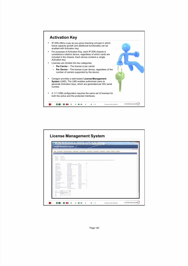
7/25/2019 Handbook - FibeAir IP-20G Advanced Training Course T8.0 ver1.pdf
http://slidepdf.com/reader/full/handbook-fibeair-ip-20g-advanced-training-course-t80-ver1pdf 138/277
Proprietary and Confidential
Activation Key
3
IP-20N offers a pay as-you-grow licensing concept in which
future capacity growth and additional functionality can beenabled with Activation key.
For purposes of Activation Key, each IP-20N chassis is
considered a distinct device, regardless of which cards are
included in the chassis. Each device contains a single
Activation key.
Licenses are divided into two categories:
Per Carrier The license is per carrier
Per Device The license is per device, regardless of the
number of carriers supported by the device.
Ceragon provides a web-based License Management
System (LMS). The LMS enables authorized users to
generate Activation keys, which are generated per IDU serial
number.
A 1+1 HSB configuration requires the same set of licenses for
both the active and the protected interfaces.
Proprietary and Confidential
License Management System
4
Page 142

7/25/2019 Handbook - FibeAir IP-20G Advanced Training Course T8.0 ver1.pdf
http://slidepdf.com/reader/full/handbook-fibeair-ip-20g-advanced-training-course-t80-ver1pdf 139/277
Proprietary and Confidential
Activation key generating
5
Serial Number
important for
activation key
generating
Proprietary and Confidential
DEMO License
6
A demo license is available that enables all features for 60 days.
The demo license expires 60 days from the time it was activated,
and the most recent valid license goes into effect.
The 60-day period is only counted when the system is powered up.
10 days before the demo license expires, an alarm is raised
indicating to the user that the demo license is about to expire.
Page 143
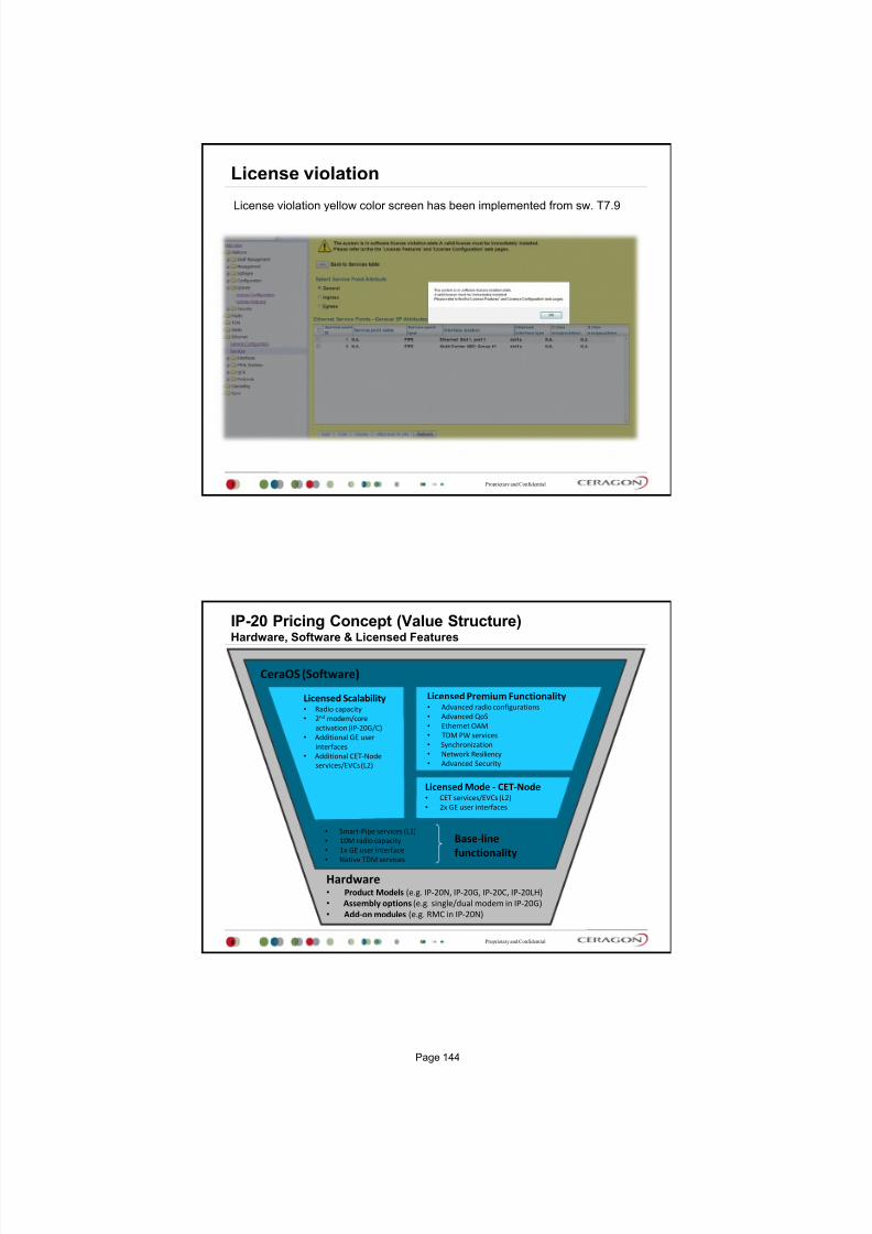
7/25/2019 Handbook - FibeAir IP-20G Advanced Training Course T8.0 ver1.pdf
http://slidepdf.com/reader/full/handbook-fibeair-ip-20g-advanced-training-course-t80-ver1pdf 140/277
Proprietary and Confidential
License violation
7
License violation yellow color screen has been implemented from sw. T7.9
Proprietary and Confidential
IP-20 Pricing Concept (Value Structure)Hardware, Software & Licensed Features
8
Hardware Product Models (e.g. IP‐20N, IP‐20G, IP‐20C, IP‐20LH)
Assembly options (e.g. single/dual modem in IP‐20G)
Add‐on modules (e.g. RMC in IP‐20N)
Smart‐Pipe services (L1)
10M radio capacity
1x GE user interface Native TDM services
Licensed Scalability Radio capacity
2nd modem/core
activation (IP‐20G/C)
Additional GE user
interfaces
Additional CET‐Node
services/EVCs (L2)
Licensed Premium Functionality Advanced radio configurations
Advanced QoS
Ethernet OAM
TDM PW services
Synchronization
Network Resiliency
Advanced Security
Licensed Mode ‐ CET‐Node CET services/EVCs (L2)
2x GE user interfaces
Base‐line
functionality
CeraOS (Software)
Page 144

7/25/2019 Handbook - FibeAir IP-20G Advanced Training Course T8.0 ver1.pdf
http://slidepdf.com/reader/full/handbook-fibeair-ip-20g-advanced-training-course-t80-ver1pdf 141/277
Proprietary and Confidential
IP-20 Activation Key Scheme
9
Per Node
Premium Functionality
QoS group
Enhanced Packet Buffer
Frame Cut Through
H-QoS
Sync group
Sync-Unit
IEEE-1588 TC
IEEE-1588 OC
IEEE-1588 BC
Redundancy/Resiliency group
Network Resiliency
Main Card Redundancy - HA
Ethernet OAM group
Eth-OAM FM
ETH-OAM PM
TDM group
TDM PW Security
Secure management
Per Carrier
Scalability
Radio capacity
Advanced radio configurations
ACM
XPIC
Multi-Carrier ABC
MIMO
Header De-duplication
Per Node scalability
CET-Node mode/scalability
Edge (8 services/EVCs)
Agg-Lvl-1 (64 services/EVCs)
Agg-Lvl-2 (1024 services/EVCs)
General node scalability
2nd modem activation (IP-20G only)
2nd core activation (IP-20C only)
GE user interfaces
Proprietary and Confidential
Licensed Features
10
License Name Description
Radio Capacity License
Enables you to increase your systems radio capacity in
gradual steps by upgrading your capacity license.
Without a capacity license, each carrier has a capacity
of 10 Mbps. Licensed capacity is available from 50
Mbps to 500 Mbps. Each RMC card can be licensed for
a different capacity.
IP‐20‐SL‐ACM
Enables the use of Adaptive Coding and Modulation
(ACM) scripts. A separate license is required per core.
IP‐20‐SL‐MC‐ABC Enables Multi‐Carrier ABC.
IP‐20‐SL‐Header‐DeDuplication
Enables the use of Header De‐Duplication, which can
be configured to operate at L2 through L4.
IP‐20‐SL‐XPIC
Enables the use of Cross Polarization Interface
Canceller (XPIC). A separate license is required for each
core in the XPIC pair.
Page 145

7/25/2019 Handbook - FibeAir IP-20G Advanced Training Course T8.0 ver1.pdf
http://slidepdf.com/reader/full/handbook-fibeair-ip-20g-advanced-training-course-t80-ver1pdf 142/277
Proprietary and Confidential
Licensed Features
11
License Name Description
IP‐20‐SL‐GE‐Port
Enables the use of a TCC/LIC Ethernet traffic port in GE
mode (10/100/1000baseT or 1000baseX). An activation
key is required for each Ethernet traffic port that is used
on the device. An activation key can be installed
multiple times with dynamic allocation inside the unit
to enable multiple GE ports.
Note: All Ethernet traffic ports are enabled in FE mode
(10/100baseT) by default without requiring any
activation key.
IP‐20‐SL‐Main‐Card‐Redundancy
Enables the use of a second TCC in a 2RU chassis for
High Availability.
Proprietary and Confidential
Licensed Features
12
License Name Description
Edge CET Node
Enables Carrier Ethernet Transport (CET) and a number
of Ethernet services (EVCs), depending on the type of
CET Node license:
Edge CET Node Up to 8 EVCs.
Aggregation Level 1 CET Node Up to 64 EVCs.
Aggregation Level 2 CET Node Up to 1024 EVCs.
A CET Node license also enables the following:
Network resiliency (MSTP/RSTP) for all services.
Full QoS for all services including basic queue buffer
management (fixed queues buffer size limit, tail‐
drop only) and eight queues per port, no H‐QoS.
LAG Support
P‐20‐SL‐Network‐Resiliency
Enables the following protocols for improving network
resiliency:
G.8032
TDM (PW) services 1:1/1+1 path protection
Page 146

7/25/2019 Handbook - FibeAir IP-20G Advanced Training Course T8.0 ver1.pdf
http://slidepdf.com/reader/full/handbook-fibeair-ip-20g-advanced-training-course-t80-ver1pdf 143/277
Proprietary and Confidential
Licensed Features
13
License Name Description
IP‐20‐SL‐H‐QoSH‐QoS
Enables H‐QoS. This license is required to add service‐
bundles with dedicated queues to interfaces. Without
this license, only the default eight queues per port are
supported. (Planned for future release)
IP‐20‐SL‐Enh‐Packet‐Buffer
Enables configurable (non‐default) queue buffer size
limit for Green and Yellow frames. Also enables WRED.
The default queue buffer size limit is 1Mbits for Green
frames and 0.5 Mbits for Yellow frames.
IP‐20‐SL‐Sync‐Unit
Enables the G.8262 synchronization unit. This license is
required in order to provide end‐to‐end synchronization
distribution on the physical layer. This license is also
required to use Synchronous Ethernet (SyncE).
P‐20‐SL‐Frame‐Cut‐Through Enables Frame Cut‐Through.
IP‐20‐SL‐TDM‐PW
Enables TDM pseudowire services on units with TDM
interfaces. Without this activation key, only native TDM
services are supported.
Proprietary and Confidential
Licensed Features
14
License Name Description
P‐20‐SL‐Secure‐Management Enables secure management protocols (SSH, HTTPS,
SFTP, SNMPv3, and RADIUS).
IP‐20‐SL‐Eth‐OAM‐FM Enables Connectivity Fault Management (FM) per
Y.1731/ 802.1ag and 802.3ah (CET mode only).
IP‐20‐SL‐Eth‐OAM‐PM Enables performance monitoring pursuant to Y.1731
(CET mode only).
Page 147

7/25/2019 Handbook - FibeAir IP-20G Advanced Training Course T8.0 ver1.pdf
http://slidepdf.com/reader/full/handbook-fibeair-ip-20g-advanced-training-course-t80-ver1pdf 144/277
Proprietary and Confidential
Activation Key Configuration
15
Sanction state
If an Activation Key Violation alarm has occurred, and the 48-hour activation key violation grace period
has expired without the system having been brought into conformance with the activation-key-enabled
capacity and feature set, Yes appears in this field to indicate that the system is in an Activation Key
Violation sanction state.
All other alarms are hidden until the capacity and features in use are brought within the activation-key-
enabled capacity and feature set
Proprietary and Confidential
Activation Key Overview
16
Page 148

7/25/2019 Handbook - FibeAir IP-20G Advanced Training Course T8.0 ver1.pdf
http://slidepdf.com/reader/full/handbook-fibeair-ip-20g-advanced-training-course-t80-ver1pdf 145/277
Thank You
Page 149
7/25/2019 Handbook - FibeAir IP-20G Advanced Training Course T8.0 ver1.pdf
http://slidepdf.com/reader/full/handbook-fibeair-ip-20g-advanced-training-course-t80-ver1pdf 146/277
Version 5
Service Model in IP-20
November 2014
Proprietary and Confidential
Agenda
2
IP-20 Ethernet Capabilities
Service Model in General
What is a Service ?
What is a Service point?
Services in IP-20 Family & Services attributes
1. Point to Point Service
2. Multipoint Service
3. Management Service
Service Point in IP-20 Family
1. Pipe Service Point
2. Service Access Point (SAP)
3. Service Network Point (SNP)
4. Management Service Point (MNG)
Service Points classification and attributes
Examples for Services and Service points
Logical VS. Physical Port
Page 151

7/25/2019 Handbook - FibeAir IP-20G Advanced Training Course T8.0 ver1.pdf
http://slidepdf.com/reader/full/handbook-fibeair-ip-20g-advanced-training-course-t80-ver1pdf 147/277
Proprietary and Confidential
IP-20s Ethernet Capabilities
3
Up to 1024 services (1025 reserved for Management) Up to 32 service points per service (30 SPs for MNG service)
All service types:
Multipoint (E-LAN)
Point-to-Point (E-Line)
Point-to-Multipoint (E-Tree)
Smart Pipe
Management
128K MAC learning table per service - ability to limit MAC learning perservice
Split horizon between service points
Flexible transport and encapsulation via 802.1q, 802.1ad (Q-in-Q), andMPLS-TP, with tag manipulation possible at egress
High precision, flexible frame synchronization solution combining SyncEand 1588v2
Hierarchical QoS with 8K service level queues, deep buffering, hierarchicalscheduling via WFQ and Strict priority, and shaping at each level
Proprietary and Confidential
IP-20s Ethernet Capabilities
4
Hierarchical two-rate three-Color policers
Port based Unicast, Multicast, Broadcast, Ethertype
Service-based
CoS-based
Up to four link aggregation groups (LAG)
Hashing based on L2, L3, MPLS, and L4
Enhanced <50msec network level resiliency (G.8032) for ring/mesh support
IP-20 is fully MEF-9 and MEF-14 certified for all Carrier Ethernet services.
Page 152

7/25/2019 Handbook - FibeAir IP-20G Advanced Training Course T8.0 ver1.pdf
http://slidepdf.com/reader/full/handbook-fibeair-ip-20g-advanced-training-course-t80-ver1pdf 148/277
Service model in General
5
Proprietary and Confidential
What is a Service?
6
A virtual bridge, connecting two or more interfaces
Bridge is a device that separates two or more network segments
within one logical network
Interfaces are usually referred to physical ports but can also be logical
ports
Page 153

7/25/2019 Handbook - FibeAir IP-20G Advanced Training Course T8.0 ver1.pdf
http://slidepdf.com/reader/full/handbook-fibeair-ip-20g-advanced-training-course-t80-ver1pdf 149/277
Proprietary and Confidential
4
3
1
2
Service Model
7
Service #1
Service #2
Proprietary and Confidential
Service points
8
Service points are logical entities attached to the interfaces that make up the
service. Service points define the movement of frames through the service.
Without service points, a service is simply a virtual bridge with no ingress or
egress interfaces.
The Route is your first service point
towards the bridge
Rails are second service point
towards the bridge
Page 154

7/25/2019 Handbook - FibeAir IP-20G Advanced Training Course T8.0 ver1.pdf
http://slidepdf.com/reader/full/handbook-fibeair-ip-20g-advanced-training-course-t80-ver1pdf 150/277
Proprietary and Confidential
4
3
1
2
What is a service point?
9
Service #1
Service #2
SP SP
SP SP
SPSP
Services in IP-20 Family
10
Page 155

7/25/2019 Handbook - FibeAir IP-20G Advanced Training Course T8.0 ver1.pdf
http://slidepdf.com/reader/full/handbook-fibeair-ip-20g-advanced-training-course-t80-ver1pdf 151/277
Proprietary and Confidential
IP-20 Services
11
IP20 supports the following services types:
1. Point-to-Point Service (P2P)
2. Multipoint Service (MP)
3. Management Service (MNG)
4. Point-to-Multipoint Service (E-Tree)
E-Tree services are planned for future release.
Proprietary and Confidential
3
Point to Point Service (P2P)
12
Point-to-point services are used to provide connectivity between two
interfaces of the network element.
When traffic ingresses via one side of the service, it is immediately directed
to the other side according to ingress and egress tunneling rules.
This type of service contains exactly two service points and does not require
MAC address-based learning or forwarding
41
2SAPPIPE
SAPPIPE
Page 156

7/25/2019 Handbook - FibeAir IP-20G Advanced Training Course T8.0 ver1.pdf
http://slidepdf.com/reader/full/handbook-fibeair-ip-20g-advanced-training-course-t80-ver1pdf 152/277
Proprietary and Confidential
Multipoint Service (MP)
13
Multipoint services are used to provide connectivity between two or more service points.
When traffic ingresses via one service point, it is directed to one of the service points in the
service, other than the ingress service point, according to ingress and egress tunneling rules, and
based on the learning and forwarding mechanism.
If the destination MAC address is not known by the learning and forwarding mechanism, the
arriving frame is flooded to all the other service points in the service except the ingress service
point.
3
41
2
SNP
SNP
SAP
SAP
Proprietary and Confidential
Management Service (MNG)
14
The management service is a multipoint service that connects the two local
management ports, the network element host CPU, and the traffic ports into a single
service. The service behavior is same as the Multipoint service behavior.
The management service is pre-defined with Service ID 1025.
4
1
2
M a n a g e m e n t p o r t
1
2 T r a f f i c p o r t s
CPU
SNPSAP
Service ID 1025
Page 157

7/25/2019 Handbook - FibeAir IP-20G Advanced Training Course T8.0 ver1.pdf
http://slidepdf.com/reader/full/handbook-fibeair-ip-20g-advanced-training-course-t80-ver1pdf 153/277
Proprietary and Confidential
Service Attributes
15
Service ID - 1 - 1024
Service Type P2P, MP, MNG
Service Admin Mode Operational, Reserved
EVC-ID - Ethernet Virtual Connection ID (End-to-end).
EVC Description
Maximum Dynamic MAC Address Learning per Service
Static MAC Address Configuration
CoS Mode & Default CoS
xSTP Instance The spanning tree instance ID (1-63)
Split Horizon Group - (Enable/Disable)
IP-20 Service Points
16
Page 158

7/25/2019 Handbook - FibeAir IP-20G Advanced Training Course T8.0 ver1.pdf
http://slidepdf.com/reader/full/handbook-fibeair-ip-20g-advanced-training-course-t80-ver1pdf 154/277
Proprietary and Confidential
Service points
SAP SNP
Pipe Service Point
Management Service Point
Proprietary and Confidential
Service Access Port SAP & Service Network Point SNP
18
Page 159

7/25/2019 Handbook - FibeAir IP-20G Advanced Training Course T8.0 ver1.pdf
http://slidepdf.com/reader/full/handbook-fibeair-ip-20g-advanced-training-course-t80-ver1pdf 155/277
Proprietary and Confidential
Service Access Port SAP & Service Network Point SNP
19
Proprietary and Confidential
Management (MNG) Service Point
20
Only used for management services
Page 160
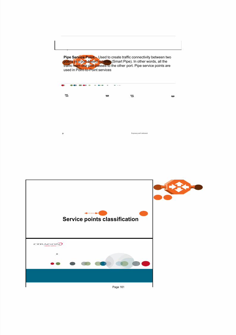
7/25/2019 Handbook - FibeAir IP-20G Advanced Training Course T8.0 ver1.pdf
http://slidepdf.com/reader/full/handbook-fibeair-ip-20g-advanced-training-course-t80-ver1pdf 156/277
Proprietary and Confidential
Pipe Service Points
21
Pipe Service Point Used to create traffic connectivity between twopoints in a port-based manner (Smart Pipe). In other words, all the
traffic from one port passes to the other port. Pipe service points are
used in Point-to-Point services
SAPSAPPIPE PIPE
SAPSAPPIPE PIPE
Service points classification
22
Page 161

7/25/2019 Handbook - FibeAir IP-20G Advanced Training Course T8.0 ver1.pdf
http://slidepdf.com/reader/full/handbook-fibeair-ip-20g-advanced-training-course-t80-ver1pdf 157/277
Proprietary and Confidential
Service Point Interface Types
23
Interface Type Types of Frames Applies to SP Type
Dot1q A single C‐VLAN is classified into the service
point
All
S‐tag A single S‐VLAN is classified into the service
point
SNP and MNG
Bundle‐C A set of C‐VLANs is classified into the service
point
SAP
Bundle‐S A single S‐VLAN and a set of C‐VLAN are
classified into the service point
SAP
All‐to‐One All C‐VLANs, S‐VLANs with TPID diff than the
system one and untagged frames that enter
the interface are classified into the service
point
SAP
Q ‐in‐Q A single S‐VLAN and C‐VLAN combination is
classified into the service point
SAP and MNG
Proprietary and Confidential
Service Points
24
Service
Page 162

7/25/2019 Handbook - FibeAir IP-20G Advanced Training Course T8.0 ver1.pdf
http://slidepdf.com/reader/full/handbook-fibeair-ip-20g-advanced-training-course-t80-ver1pdf 158/277
Proprietary and Confidential25
Service
Proprietary and Confidential
Service Point Types that can Co-Exist on the Same Interface
26
Service point type
MNG SAP SNP Pipe
Service Type Management Yes No No No
Point-to-Point No Yes Yes Yes
Multipoint No Yes Yes No
Service point Types per Service Type
MNG SP SAP SP SNP SP Pipe SP
MNG SP Only one MNG SP is
allowed per interface.
Yes Yes Yes
SAP SP Yes Yes No No
SNP SP Yes No Yes No
PIPE SP Yes No No Only one Pipe SP is
allowed per interface.
Service Point Types that can Co-Exist on the Same Interface
Page 163

7/25/2019 Handbook - FibeAir IP-20G Advanced Training Course T8.0 ver1.pdf
http://slidepdf.com/reader/full/handbook-fibeair-ip-20g-advanced-training-course-t80-ver1pdf 159/277
Proprietary and Confidential27
Service Point Types that can Co-Exist on the Same Interface
Proprietary and Confidential
Example of dot1q services
28
SAP1
ptp 1
ptp 2
C‐Vlan
10 SAP 1
20 SAP 2
C‐Vlan
10 SAP 3
C‐Vlan
120 SAP 4
SAP
SNP
SAP2
SAP3
SAP4
Transport Vlan EVC
100 ptp1
200 ptp2
The classification to PtP1 and PtP2 is based
on one c‐vlan.
PtP 1 uses same c‐vlan as the classification
at both ends
PtP 2 uses different c‐vlan as the
classification at both ends.
PtP1 and PtP2 uses the transport vlan
inside the network. The original c‐vlan is
not sent inside the network.
Page 164
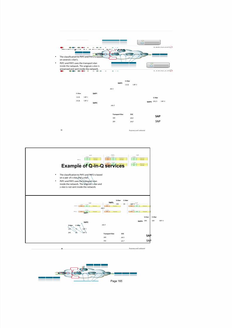
7/25/2019 Handbook - FibeAir IP-20G Advanced Training Course T8.0 ver1.pdf
http://slidepdf.com/reader/full/handbook-fibeair-ip-20g-advanced-training-course-t80-ver1pdf 160/277
Proprietary and Confidential
Example of bundle services
29
SAP1
ptp 1
ptp 2
C‐Vlan
1 0, 11 S AP 1
2 0, 21 S AP 2
C‐Vlan
1 0, 11 S AP 3
C‐Vlan
20 ,2 1 S AP 4
SAP
SNP
SAP2
SAP3
SAP4
Transport Vlan EVC
100 ptp1
200 ptp2
The classification to PtP1 and PtP2 is based
on several c‐vlans.
PtP1 and PtP2 uses the transport vlan
inside the network. The original c‐vlan is
preserved and sent inside the network.
Proprietary and Confidential
Example of Q-in-Q services
30
SAP1
ptp 1
ptp 2S‐Vlan C
‐Vlan
230 10 SAP 1
240 20 SAP 2
S‐Vlan C‐Vlan
230 10 SAP 3
S‐Vlan C‐Vlan
340 320 SAP 4
SAP
SNP
SAP2
SAP3
SAP4
Transport Vlan EVC
100 ptp1
200 ptp2
The classification to PtP1 and PtP2 is based
on a pair of c‐vlan and s‐vlan.
PtP1 and PtP2 uses the transport vlan
inside the network. The original c‐vlan and
s‐vlan is not sent inside the network.
Page 165

7/25/2019 Handbook - FibeAir IP-20G Advanced Training Course T8.0 ver1.pdf
http://slidepdf.com/reader/full/handbook-fibeair-ip-20g-advanced-training-course-t80-ver1pdf 161/277
Service points Attributes
31
Proprietary and Confidential
Service Point Attributes
As described above, traffic ingresses and egresses the service via service
points. The service point attributes are divided into two types:
Ingress Attributes Define how frames are handled upon ingress, e.g.,
policing and MAC address learning.
Egress Attributes Define how frames are handled upon egress, e.g.,
preservation of the ingress CoS value upon egress, VLAN swapping.
Page 166

7/25/2019 Handbook - FibeAir IP-20G Advanced Training Course T8.0 ver1.pdf
http://slidepdf.com/reader/full/handbook-fibeair-ip-20g-advanced-training-course-t80-ver1pdf 162/277
Proprietary and Confidential
Service Point Attributes
33
General Ingress Egress
Service Point ID Learning Admin C‐VLAN CoS Preservation
Service Point Name Allow Flooding C‐VLAN Preservation
Service Point Type Allow Broadcast S‐VLAN CoS Preservation
Interface CoS Mode Marking Admin
Interface Type Default CoS Service Bundle ID
C‐VLAN Encapsulation
S‐VLAN Encapsulation
Proprietary and Confidential
Service Point General Attributes
34
General
Service Point ID
Service Point Name
Service Point Type
Interface
Interface Type
C‐VLAN Encapsulation
S‐VLAN Encapsulation
Service Point ID number for service point inside
the same service
Service Point Name The Name for service point
if is needed
Service Point Type- SAP, SNP, MNG, PIPE
Interface - The logical interface on which the
service point is located
Interface Type Dot1q, S-Tag, Bundle-C, Bundle-
S, All-to-One, Q-in-Q
C-Vlan Encapsulation - The C-VLAN classified
into the service point
S-Vlan Encapsulation - The S-VLAN classifiedinto the service point
Page 167

7/25/2019 Handbook - FibeAir IP-20G Advanced Training Course T8.0 ver1.pdf
http://slidepdf.com/reader/full/handbook-fibeair-ip-20g-advanced-training-course-t80-ver1pdf 163/277
Proprietary and Confidential
Service Point Ingress Attribute
35
Ingress
Learning Admin
Allow Flooding
Allow Broadcast
CoS Mode
Default CoS
Learning Admin - Indicates whether MACaddress learning is enabled or disabled
Allow Flooding - Indicates whether incoming
frames with unknown MAC addresses are
forwarded to other service points via flooding
Allow Broadcast - Indicates whether frames with
a broadcast destination MAC address are allowed
to ingress the service via this service point
CoS Mode - Indicates how the service point
handles the CoS of frames that pass through the
service point.
Default CoS The service point CoS. If the CoS
Mode is set to overwrite the CoS decision made at
the interface level, this is the CoS value assigned
to frames that ingress the service point.
Proprietary and Confidential
Service Point Egress Attribute
36
Egress
C‐VLAN CoS Preservation
C‐VLAN Preservation
S‐VLAN CoS Preservation
Marking Admin
Service Bundle ID
C-Vlan CoS Preservation - Indicates whether the
original C-VLAN CoS value is preserved or
restored for frames egressing from the service
point
C-Vlan Preservation - Indicates whether the
original C-VLAN ID is preserved or restored for
frames egressing from the service point
S-Vlan CoS Preservation - Indicates whether the
original S-VLAN CoS value is preserved or
restored for frames egressing from the service
point
Marking Admin - Indicates whether re-marking of
the outer VLAN (C-VLAN or S-VLAN) of tagged
frames that pass through the service point isenabled
Service Bundle ID - This can be used to assign
one of the available service bundles from the H-
QoS hierarchy queues to the service point
Page 168
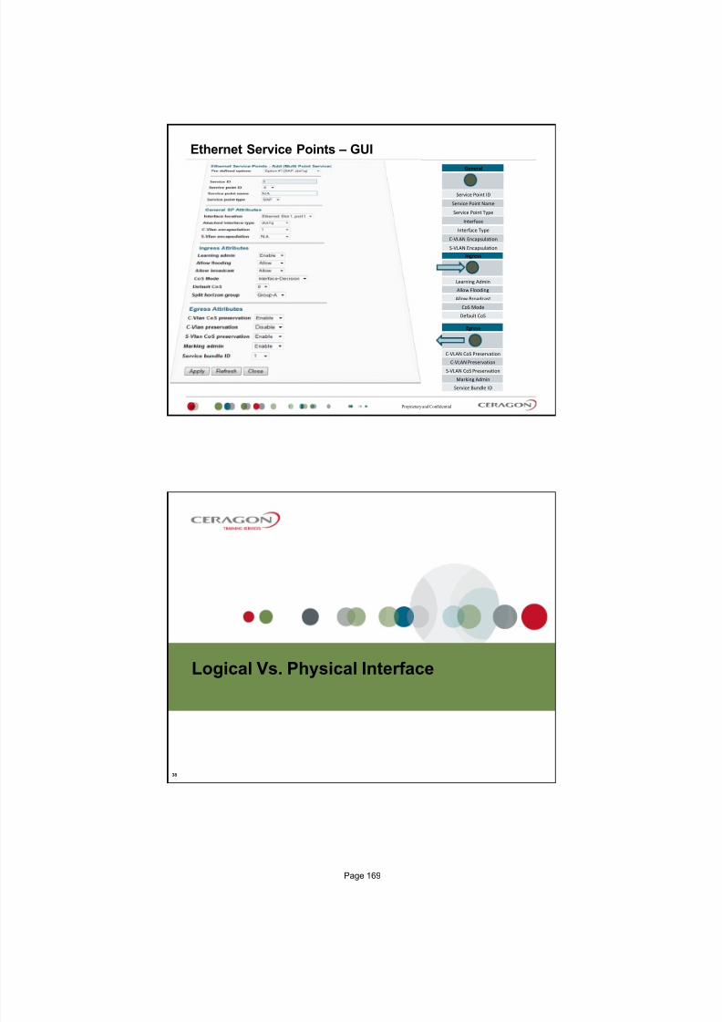
7/25/2019 Handbook - FibeAir IP-20G Advanced Training Course T8.0 ver1.pdf
http://slidepdf.com/reader/full/handbook-fibeair-ip-20g-advanced-training-course-t80-ver1pdf 164/277
Proprietary and Confidential37
Egress
C‐VLAN CoS Preservation
C‐VLAN Preservation
S‐VLAN CoS Preservation
Marking Admin
Service Bundle ID
Ingress
Learning Admin
Allow Flooding
Allow Broadcast
CoS Mode
Default CoS
General
Service Point ID
Service Point Name
Service Point Type
Interface
Interface Type
C‐VLAN Encapsulation
S‐VLAN Encapsulation
Ethernet Service Points GUI
Logical Vs. Physical Interface
38
Page 169

7/25/2019 Handbook - FibeAir IP-20G Advanced Training Course T8.0 ver1.pdf
http://slidepdf.com/reader/full/handbook-fibeair-ip-20g-advanced-training-course-t80-ver1pdf 165/277
Proprietary and Confidential
Logical and physical interface
39
Service Demo
40
Page 170

7/25/2019 Handbook - FibeAir IP-20G Advanced Training Course T8.0 ver1.pdf
http://slidepdf.com/reader/full/handbook-fibeair-ip-20g-advanced-training-course-t80-ver1pdf 166/277
Proprietary and Confidential
The Setup
41
IP-20N
IP-20C/S/E
IP-20G
Proprietary and Confidential
Creating the Service
42
Page 171

7/25/2019 Handbook - FibeAir IP-20G Advanced Training Course T8.0 ver1.pdf
http://slidepdf.com/reader/full/handbook-fibeair-ip-20g-advanced-training-course-t80-ver1pdf 167/277
Proprietary and Confidential
Attaching Service Points
43
Proprietary and Confidential
Attaching Service Points
44
Page 172

7/25/2019 Handbook - FibeAir IP-20G Advanced Training Course T8.0 ver1.pdf
http://slidepdf.com/reader/full/handbook-fibeair-ip-20g-advanced-training-course-t80-ver1pdf 168/277
Proprietary and Confidential
Attaching Service Points
45
Proprietary and Confidential
Questions?
46
Page 173

7/25/2019 Handbook - FibeAir IP-20G Advanced Training Course T8.0 ver1.pdf
http://slidepdf.com/reader/full/handbook-fibeair-ip-20g-advanced-training-course-t80-ver1pdf 169/277
Thank You
Page 174

7/25/2019 Handbook - FibeAir IP-20G Advanced Training Course T8.0 ver1.pdf
http://slidepdf.com/reader/full/handbook-fibeair-ip-20g-advanced-training-course-t80-ver1pdf 170/277
IP-20G
May 2015, ver5
Quality of Service
Proprietary and Confidential
Agenda
2
Standard QoS VS. H-QoS
QoS in General
QoS in IP-20C
Classification
Marker
Bandwidth Profile
Policing
Queues Manager
WRED
Scheduler
Shaper
Page 175

7/25/2019 Handbook - FibeAir IP-20G Advanced Training Course T8.0 ver1.pdf
http://slidepdf.com/reader/full/handbook-fibeair-ip-20g-advanced-training-course-t80-ver1pdf 171/277
Proprietary and Confidential
Hierarchical QoS (H-QoS) vs. Standard QoS
3
Differentiation between
different traffic classes (CoS)
Services within the same traffic
class are treated as a single
aggregate with no isolation
Limited per-service visibility
and control
Each service gets its own
personalized treatment
TDM-grade performance
providing per-service full
visibility and control
Standard QoS
EthernetRadio
Eth.traffic
Service 1
Service 2
Service 3
Voice
Streaming
Data
V
S
D
V
V
S
S
D
D
H-QoS
EthernetRadio
Service 1
Service 2
Service 3
V
S
D
Service 1
Service 2
Service 3
V
S
D
V
S
D
Proprietary and Confidential
Backhaul Sharing Fairness & Bursts Isolation
4
MSC/RNC/S-GWOperator 2
Shared Backhaul
MSC/RNC/S-GW
Operator 1
Shared Site
Shared Site
Shared Site
Operator 1
Operator 2
Operator 1
Operator 2
Operator 1
Operator 2
Operator 1
Operator 2
Same CoS
Same CoS HQoS
Standard
QoS
N >> 8
Page 176
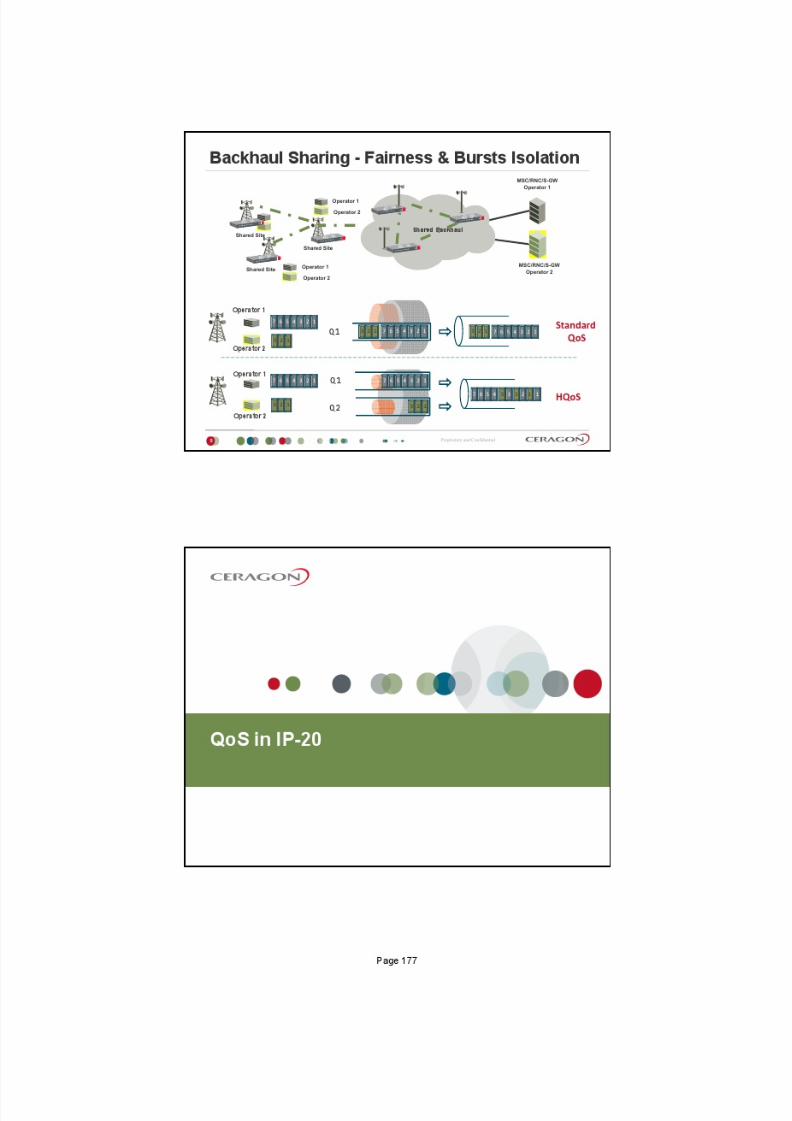
7/25/2019 Handbook - FibeAir IP-20G Advanced Training Course T8.0 ver1.pdf
http://slidepdf.com/reader/full/handbook-fibeair-ip-20g-advanced-training-course-t80-ver1pdf 172/277

7/25/2019 Handbook - FibeAir IP-20G Advanced Training Course T8.0 ver1.pdf
http://slidepdf.com/reader/full/handbook-fibeair-ip-20g-advanced-training-course-t80-ver1pdf 173/277
Proprietary and Confidential
How does it Work?
7
E gr e s s P or t
I n
r e s s P or t
Ethernet frame
V.ID = 100
P-Bit = 5
IP Packet
DSCP = 0
Proprietary and Confidential
General Overview
8
Service
E gr e s s P or t
I n gr e s s P or t
Policers
Shapers
Queues
Scheduler
Priority WFQ
Ingress Egress
WRED
Marker
Page 178

7/25/2019 Handbook - FibeAir IP-20G Advanced Training Course T8.0 ver1.pdf
http://slidepdf.com/reader/full/handbook-fibeair-ip-20g-advanced-training-course-t80-ver1pdf 174/277
Classification
9
Proprietary and Confidential
Classification
10
3 Hierarchies
Port (aka 1H)
VLAN (aka 1.5H)
Service Point (aka 2H)
Service (aka 3H)
Port level classification
VLAN P-bits
DSCP
MPLS EXP bits
Default classification
Port
VLAN
SP
Service
Page 179

7/25/2019 Handbook - FibeAir IP-20G Advanced Training Course T8.0 ver1.pdf
http://slidepdf.com/reader/full/handbook-fibeair-ip-20g-advanced-training-course-t80-ver1pdf 175/277
Proprietary and Confidential
Classification Hierarchies
11
SAPSNP
SAPSAP
SAPSNP
SAPSAPPortPortPort VLANVLANVLAN
Service H3
SP H2Port H1VLAN H1,5
Port level classification1. VLAN P-bits
2. DSCP
3. MPLS EXP bits
4. Default classification
Service Points classification1. Preserve previous decision
2. Default CoSService classification1. Preserve previous decision
2. Default CoS
Calculated CoS =H3>H2>H1
Service #1
Proprietary and Confidential
CoS Classification
12
SNP
SNP
SAP
SAP
SNP
SNP
SAP
SAP
VLANVLANVLAN
Service H3
SP1 H2Port1 H1 VLAN H1,5
SP2 H2
Port 2Port 2Port 2 VLANVLANVLAN
Port2 H1 VLAN H1,5
Port 1Port 1Port 1
Port level classification1. VLAN P-bits
2. DSCP
3. MPLS EXP bits
4. Default classification
Service Points classification1. Preserve previous decision
2. Default CoS
Service classification1. Preserve previous decision
2. Default CoS
Port level classification1. VLAN P-bits
2. DSCP
3. MPLS EXP bits
4. Default classification
Service Points classification1. Preserve previous decision
2. Default CoS
Calculated CoS =H3>H2>H1
Page 180

7/25/2019 Handbook - FibeAir IP-20G Advanced Training Course T8.0 ver1.pdf
http://slidepdf.com/reader/full/handbook-fibeair-ip-20g-advanced-training-course-t80-ver1pdf 176/277
Proprietary and Confidential
4
Classification example
13
Customer 1
Customer 2
Customer 3
Customer 3
Proprietary and Confidential
Classification 1H
14
1st Priority 2nd Priority 3th Priority 4th Priority
Page 181
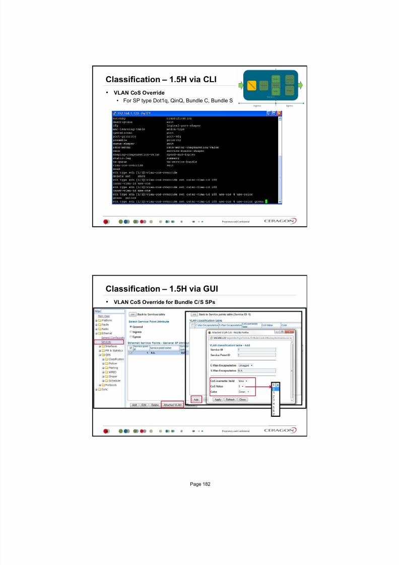
7/25/2019 Handbook - FibeAir IP-20G Advanced Training Course T8.0 ver1.pdf
http://slidepdf.com/reader/full/handbook-fibeair-ip-20g-advanced-training-course-t80-ver1pdf 177/277
Proprietary and Confidential
Classification 1.5H via CLI
15
VLAN CoS Override
For SP type Dot1q, QinQ, Bundle C, Bundle S
Proprietary and Confidential
Classification 1.5H via GUI
16
VLAN CoS Override for Bundle C/S SPs
Page 182

7/25/2019 Handbook - FibeAir IP-20G Advanced Training Course T8.0 ver1.pdf
http://slidepdf.com/reader/full/handbook-fibeair-ip-20g-advanced-training-course-t80-ver1pdf 178/277
Proprietary and Confidential
Classification 2H
17
Service Point CoS Mode
Proprietary and Confidential
Classification 3H
18
Service CoS Mode
Page 183

7/25/2019 Handbook - FibeAir IP-20G Advanced Training Course T8.0 ver1.pdf
http://slidepdf.com/reader/full/handbook-fibeair-ip-20g-advanced-training-course-t80-ver1pdf 179/277
Policing
19
Proprietary and Confidential
Ingress Policing
20
We can configure ingress policing based on
two rates three colors token bucket (MEF 10.2 TrTCM).
The token buckets order shall be as follow:
Service-Point+CoS - service policing
Service-Point - service policing
Ethertype - port policing
Frame type (unicast, multicast, broadcast) port policing.
There are 256 profiles
There are 1024 policers.
F r a m e T
y p e
E t h e r t y p e
S e r v i c e - P o i n tCoS 1
CoS 2
CoS 3
Page 184

7/25/2019 Handbook - FibeAir IP-20G Advanced Training Course T8.0 ver1.pdf
http://slidepdf.com/reader/full/handbook-fibeair-ip-20g-advanced-training-course-t80-ver1pdf 180/277
Proprietary and Confidential
Meaning of Colors
21
Guaranteed
Non Guaranteed
Dropped
Proprietary and Confidential
Bandwidth Profile (BWP)
Two Rate Three Color Marking Policer Rates & Bursts
Committed Information RateThe rate at which tokens fill the 1st bucket
CIR & CBS defines the assured bandwidth and burst
EIR & EBS improves the networks Goodput (best effort)
Committed Burst SizeThe size of the 1st bucket
Excess Information RateThe rate at which tokens fill the 2nd bucket
Excess Burst SizeThe size of the 2nd bucket
22
Page 185

7/25/2019 Handbook - FibeAir IP-20G Advanced Training Course T8.0 ver1.pdf
http://slidepdf.com/reader/full/handbook-fibeair-ip-20g-advanced-training-course-t80-ver1pdf 181/277
Proprietary and Confidential
Bandwidth Profile (BWP)Two Rate Three Color Marking Policer Modes Of Operation
Color Modes (CM)Color Blind Frames are uncolored and aremarked following policer operation
Color Aware Frames were marked before. Yellow frames jump to 2nd bucket
Most Operators use CM & CF default values (CM = blind, CF = 0)
Coupling Flag (CF)
CF = 0 the 2nd bucket is filled based on
EIR value only
CF = 1 2nd bucket is filled based on EIR
and excess tokens not used in 1st
bucket
23
Proprietary and Confidential
Defining Policer Profile
24
128000 bps
Page 186

7/25/2019 Handbook - FibeAir IP-20G Advanced Training Course T8.0 ver1.pdf
http://slidepdf.com/reader/full/handbook-fibeair-ip-20g-advanced-training-course-t80-ver1pdf 182/277
Proprietary and Confidential
Assign a Policer to a Port
25
Proprietary and Confidential
Assign a Policer to an SP
26
Page 187

7/25/2019 Handbook - FibeAir IP-20G Advanced Training Course T8.0 ver1.pdf
http://slidepdf.com/reader/full/handbook-fibeair-ip-20g-advanced-training-course-t80-ver1pdf 183/277
Queues Manager & WRED & Marker
27
Proprietary and Confidential
Queues Manager
28
Service #1
CoS 0
CoS 1
CoS 2
CoS 3
CoS 4
CoS 5
CoS 6
CoS 7
Queue 1
Queue 2
Queue 3
Queue 4
Queue 5
Queue 6
Queue 7
Queue 0
SS
SS
SS
SS
SS
SS
SS
SS
SS Single Shaper
Service
SAPSNP
SAPSAP
SAPSNP
SAPSAP
Page 188

7/25/2019 Handbook - FibeAir IP-20G Advanced Training Course T8.0 ver1.pdf
http://slidepdf.com/reader/full/handbook-fibeair-ip-20g-advanced-training-course-t80-ver1pdf 184/277
Proprietary and Confidential
WRED
29
Weighted Random Early Detect
Sliding window example
Maximum physical BW of the line
Proprietary and Confidential
WRED
30
IP-20 can hold 32 WRED profiles.
For each queue (in L4)
we can attach one of the WRED profiles.
Page 189

7/25/2019 Handbook - FibeAir IP-20G Advanced Training Course T8.0 ver1.pdf
http://slidepdf.com/reader/full/handbook-fibeair-ip-20g-advanced-training-course-t80-ver1pdf 185/277
Proprietary and Confidential
Creating WRED Profile
31
Proprietary and Confidential
Queues Manager with WRED
32
Service #1
CoS 0
CoS 1
CoS 2
CoS 3
CoS 4
CoS 5
CoS 6
CoS 7
Queue 1
Queue 2
Queue 3
Queue 4
Queue 5
Queue 6
Queue 7
Queue 0
SS
SS
SS
SS
SS
SS
SS
SS
SS Single Shaper
WRED
WRED
WRED
WRED
WRED
WRED
WRED
WRED
Service
SAPSNP
SAPSAP
SAPSNP
SAPSAP
Page 190
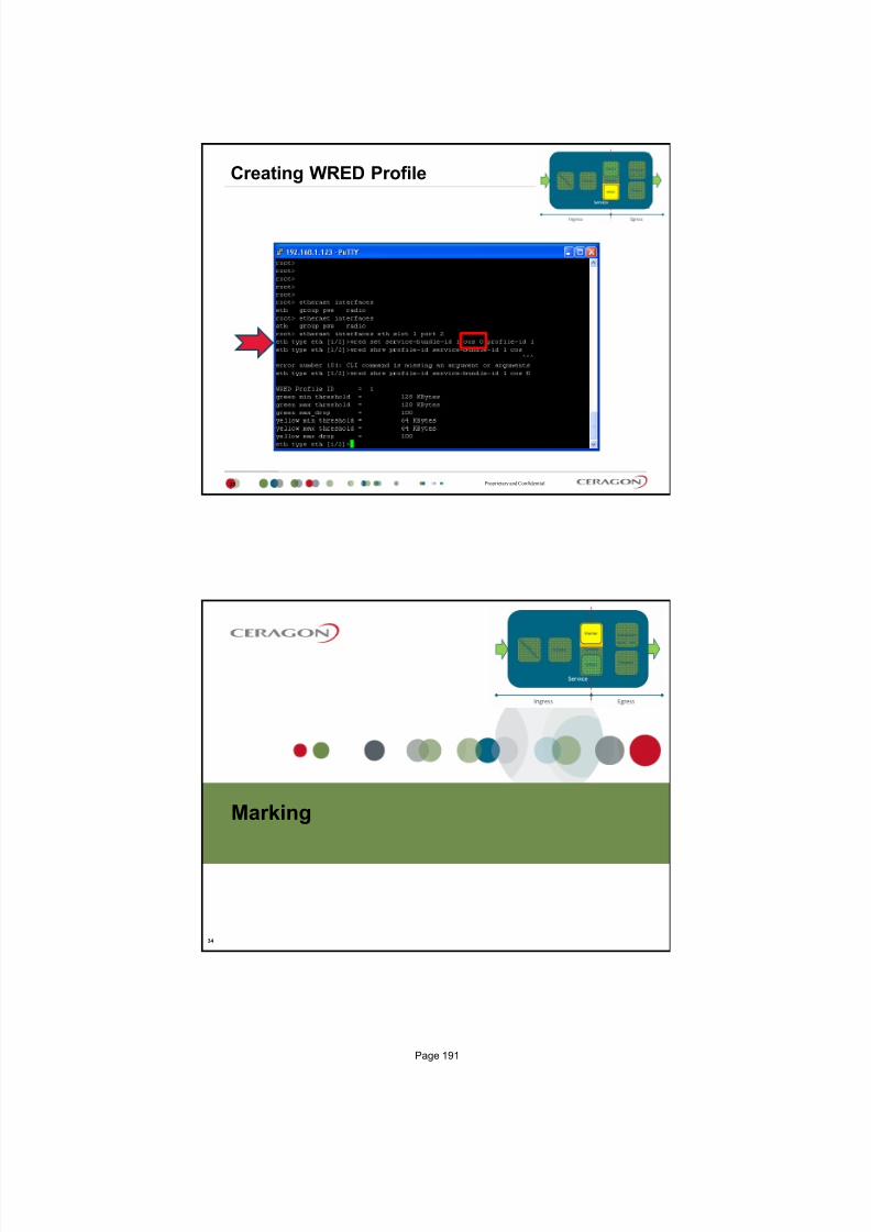
7/25/2019 Handbook - FibeAir IP-20G Advanced Training Course T8.0 ver1.pdf
http://slidepdf.com/reader/full/handbook-fibeair-ip-20g-advanced-training-course-t80-ver1pdf 186/277
Proprietary and Confidential
Creating WRED Profile
33
Marking
34
Page 191

7/25/2019 Handbook - FibeAir IP-20G Advanced Training Course T8.0 ver1.pdf
http://slidepdf.com/reader/full/handbook-fibeair-ip-20g-advanced-training-course-t80-ver1pdf 187/277
Proprietary and Confidential
Painting a Frame
35
CFI = 0, it is an Ethernet Frame, it means green color
CFI = 1, it is an Canonical format, it means yellow color
Proprietary and Confidential
CoS Preservation Marking Result
Enable Dont Care
IP‐20
Disable Enable
IP‐20
Marker
36
5
Calculated
Cos = 3/Y 3
5 Calculated
Cos = 3/G 5
Page 192

7/25/2019 Handbook - FibeAir IP-20G Advanced Training Course T8.0 ver1.pdf
http://slidepdf.com/reader/full/handbook-fibeair-ip-20g-advanced-training-course-t80-ver1pdf 188/277
Proprietary and Confidential
MARKING
MARKING
MARKING
MARKING
MARKING
MARKING
MARKING
MARKING
MARKER
38
Service #1
CoS 0
CoS 1
CoS 2
CoS 3
CoS 4
CoS 5
CoS 6
CoS 7
Queue 1
Queue 2
Queue 3
Queue 4
Queue 5
Queue 6
Queue 7
Queue 0
SS
SS
SS
SS
SS
SS
SS
SS
SS Single Shaper
WRED
WRED
WRED
WRED
WRED
WRED
WRED
WRED
Service
SAPSNP
SAPSAP
SAPSNP
SAPSAP
Scheduling and Shaping
39
Page 193

7/25/2019 Handbook - FibeAir IP-20G Advanced Training Course T8.0 ver1.pdf
http://slidepdf.com/reader/full/handbook-fibeair-ip-20g-advanced-training-course-t80-ver1pdf 189/277
Proprietary and Confidential
8
9
10
11
12
13
14
Traffic Manager Example
40
1
2
3
4
5
6
7
Service #1
1
2 4
3
Service #2
1
23
Proprietary and Confidential
D u a l S h a p e r
D u a l S h a p
e r
W F Q
W F Q
W F Q
W F Q
SP +
WFQ
SP +
WFQ
Hierarchical QoS
41
CoS Queue Level (Within a service)
Service Level Port Level
CoS 0
CoS 1
CoS 2
CoS 3
CoS 4
CoS 5
CoS 6
CoS 7
CoS 0
CoS 1
CoS 2
CoS 3
CoS 4
CoS 5
CoS 6
CoS 7
Service #1
Service #n
1st priority2nd priority3rd priority4th priority
Service Bundle Level Port Level
SS
SS
SS
SS
SS
SS
SS
SS
SS
SS
SS
SS
SS
SS
SS
SS
SS Single Shaper
SP Strict Priority
WFQ Weighted Fair Queuing
WRED
WRED
WRED
WRED
WRED
WRED
WRED
WRED
WRED
WRED
WRED
WRED
WRED
WRED
WRED
WRED
S P
M A R K I N G
S i n g l e S h a p e r
Page 194

7/25/2019 Handbook - FibeAir IP-20G Advanced Training Course T8.0 ver1.pdf
http://slidepdf.com/reader/full/handbook-fibeair-ip-20g-advanced-training-course-t80-ver1pdf 190/277
Proprietary and Confidential
D u a l S h a p e r
D u a l S h a p e r
W F Q
W F Q
W F Q
W F Q
Hierarchical QoS now
42
Service Level Port Level
CoS 0
CoS 1
CoS 2
CoS 3
CoS 4
CoS 5
CoS 6
CoS 7
CoS 0
CoS 1
CoS 2
CoS 3
CoS 4
CoS 5
CoS 6
CoS 7
Service #1
Service #n
1st priority2nd priority
3rd priority4th priority
SS
SS
SS
SS
SS
SS
SS
SS
SS
SS
SS
SS
SS
SS
SS
SS
SS Single Shaper
SP Strict Priority
WFQ Weighted Fair Queuing
WRED
WRED
WRED
WRED
WRED
WRED
WRED
WRED
WRED
WRED
WRED
WRED
WRED
WRED
WRED
WRED
S P
M A R K I N G
Port LevelCoS Queue Level (Within a service)
CoS 0
CoS 1
CoS 2
CoS 3
CoS 4
CoS 5
CoS 6
CoS 7
CoS 0
CoS 1
CoS 2
CoS 3
CoS 4
CoS 5
CoS 6
CoS 7
Service #1
Service #n
Service Bundle Level
Proprietary and Confidential
SP + WFQ
SP+WFQ Scheduling Example for one Service Bundle
43
WFQ
Service Level
S P
1st priority2nd priority3rd priority4th priority
CoS Level Port Level
CoS 7
CoS 6
CoS 5
CoS 4
CoS 3
CoS 2
CoS 1
CoS 0
WFQ
Queue 0
Queue 1
Queue 2
Queue 3
Queue 4
Queue 5
Queue 6
Queue 7 Mixed scheduling 4 strict priorities
WFQ within same priority
Shaping per port/queue8 Queues
WRED
WRED
WRED
WRED
WRED
WRED
WRED
WRED
S i n g l e S h a p e r
Page 195
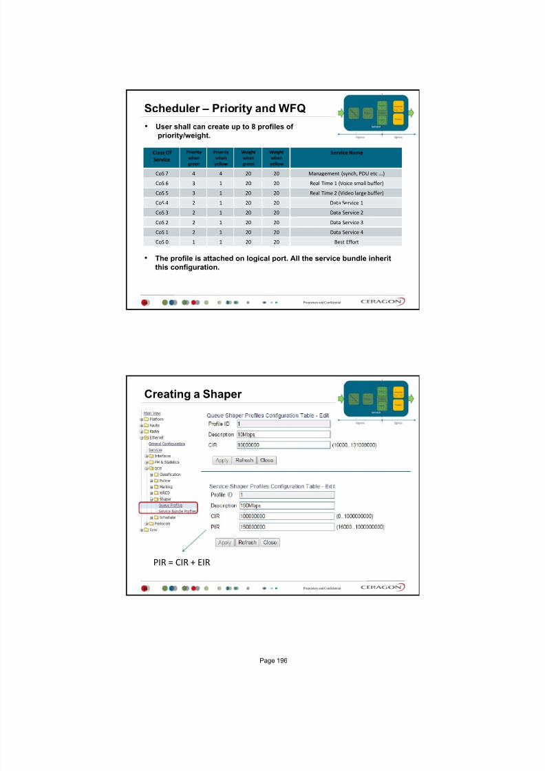
7/25/2019 Handbook - FibeAir IP-20G Advanced Training Course T8.0 ver1.pdf
http://slidepdf.com/reader/full/handbook-fibeair-ip-20g-advanced-training-course-t80-ver1pdf 191/277
Proprietary and Confidential
Scheduler Priority and WFQ
44
User shall can create up to 8 profiles of
priority/weight.
Class Of
Service
Priority
when
green
Priority
when
yellow
Weight
when
green
Weight
when
yellow
Service Name
CoS 7 4 4 20 20 Management (synch, PDU etc ...)
CoS 6 3 1 20 20 Real Time 1 (Voice small buffer)
CoS 5 3 1 20 20 Real Time 2 (Video large buffer)
CoS 4 2 1 20 20 Data Service 1
CoS 3 2 1 20 20 Data Service 2
CoS 2 2 1 20 20 Data Service 3
CoS 1 2 1 20 20 Data Service 4
CoS 0 1 1 20 20 Best Effort
The profile is attached on logical port. All the service bundle inherit
this configuration.
Proprietary and Confidential
Creating a Shaper
45
PIR = CIR + EIR
Page 196

7/25/2019 Handbook - FibeAir IP-20G Advanced Training Course T8.0 ver1.pdf
http://slidepdf.com/reader/full/handbook-fibeair-ip-20g-advanced-training-course-t80-ver1pdf 192/277
Proprietary and Confidential
Assign a Shaper
46
Proprietary and Confidential
Creating Scheduler Priority Profile
47
Page 197

7/25/2019 Handbook - FibeAir IP-20G Advanced Training Course T8.0 ver1.pdf
http://slidepdf.com/reader/full/handbook-fibeair-ip-20g-advanced-training-course-t80-ver1pdf 193/277
Proprietary and Confidential
Creating WFQ Profile
48
Proprietary and Confidential
Assign a Scheduler
49
Page 198

7/25/2019 Handbook - FibeAir IP-20G Advanced Training Course T8.0 ver1.pdf
http://slidepdf.com/reader/full/handbook-fibeair-ip-20g-advanced-training-course-t80-ver1pdf 194/277
Proprietary and Confidential50
H-QoS Summary
Policer level 1
Policer level 2Policer level 3
Service Bundle #1
Service Bundle #32
MARKING
Proprietary and Confidential
Standard QoS vs H-QoS - Summary
51
Capability Standard QoS Hierarchical QoS
Number of transmissionqueues per port
8 256
Number of service bundles 1 (always service bundle id equal 1) 32
WREDPer queue (two curves for green traffic and
for yellow traffic via the queue)
Per queue (two curves for green traffic and
for yellow traffic via the queue)
Shaping at queue level Single leaky bucket Single leaky bucket
Shaping at service bundlelevel
Dual leaky bucket Dual leaky bucket
Shaping at port levelSingle leaky bucket (this level is not relevant
since it is recommended to use service bundle
level with dual leaky bucket)
Single leaky bucket
Transmission queues priority Per queue priority (4 priorities).
Per queue priority (4 priorities). All service
bundles for a specific port inherit the 8-
queues priority settings.
Weighted fair Queue (WFQ) Queue level (between queues)Queue level (between queues)
Service Bundle level (between service
bundles)
Marker Supported Supported
Statistics
Queue level (8 queues)
Service bundle level (1 service bundle)
Port level
Queue level (256 queues)
Service bundle level (32 service bundles)
Port level
WFQ inside service bundle level is planned for future release.
Page 199

7/25/2019 Handbook - FibeAir IP-20G Advanced Training Course T8.0 ver1.pdf
http://slidepdf.com/reader/full/handbook-fibeair-ip-20g-advanced-training-course-t80-ver1pdf 195/277
Thank You
Page 200

7/25/2019 Handbook - FibeAir IP-20G Advanced Training Course T8.0 ver1.pdf
http://slidepdf.com/reader/full/handbook-fibeair-ip-20g-advanced-training-course-t80-ver1pdf 196/277
Version 2
IP- 20G XPIC Configuration
July 2015
Proprietary and Confidential
Agenda
2
System Spectrum Utilization
ACAP
ACCP
CCDP
Co-channel System
IP-20G & XPIC
XPIC Recovery mechanism
XPIC Settings
Page 201

7/25/2019 Handbook - FibeAir IP-20G Advanced Training Course T8.0 ver1.pdf
http://slidepdf.com/reader/full/handbook-fibeair-ip-20g-advanced-training-course-t80-ver1pdf 197/277

7/25/2019 Handbook - FibeAir IP-20G Advanced Training Course T8.0 ver1.pdf
http://slidepdf.com/reader/full/handbook-fibeair-ip-20g-advanced-training-course-t80-ver1pdf 198/277

7/25/2019 Handbook - FibeAir IP-20G Advanced Training Course T8.0 ver1.pdf
http://slidepdf.com/reader/full/handbook-fibeair-ip-20g-advanced-training-course-t80-ver1pdf 199/277
Proprietary and Confidential
RSL Vs. Threshold for system without CCDP
7
Thermal Noise=10*log(k*T*B*1000)
S/N=23dB for 128QAM (37 MHz)
BER>10-6RSL (dBm)
-20
-30 Nominal Input Level
-99
-96 Receiver amplifies thermal noise
-73 Threshold level BER=10-6
Fading Margin = 43dB
K Boltzmann constant
T Temperature in KelvinB Bandwidth
Time (s)
BER>10-6
Proprietary and Confidential
RSL Vs. Threshold for CCDP system without XPIC
8
Interference
S/N=23dB for 128QAM (37 MHz)
BER>10-6RSL (dBm)
-20
-30 Nominal Input Level H
-99
-96
Threshold level without interference BER=10-6
Fading Margin = 12dB
Time (s)
-65 Interference level in H (interference from V,
separation between H & V with very good antenna is35dB)
-73
-42Threshold level because of interference without XPIC
BER=10-6
BER>10-6
Page 204

7/25/2019 Handbook - FibeAir IP-20G Advanced Training Course T8.0 ver1.pdf
http://slidepdf.com/reader/full/handbook-fibeair-ip-20g-advanced-training-course-t80-ver1pdf 200/277
Proprietary and Confidential
RSL Vs. Threshold for CCDP system with XPIC
9
Interference level
S/N=23dB for 128QAM (37 MHz)
BER>10-6RSL (dBm)
-20
-30 Nominal Input Level H
Fading Margin = 38 dB
Time (s)
-65Interference level in H (interference from V, whenXPIC is not enabled
-73
Threshold level when XPIC is ON
BER>10-6
-91
XPIC will
improve
interference
for extra
26dB
-68
Interference level in H (interference from V, when
XPIC is enabled
Original Threshold level without CCDP and XPIC
configuration
Proprietary and Confidential
XPIC Recovery Mechanism
The purpose of the XPIC recovery mechanism is to save the working link whileattempting to recover the faulty polarization.
The mechanism works as follows: The indication that the recovery mechanism has been activated is a loss of
modem preamble lock, which takes place at SNR~10dB.
The first action taken by the recovery mechanism is to cause the remotetransmitter of the faulty carrier to mute, thus eliminating the disturbing signal andsaving the working link.
Following this, the mechanism attempts at intervals to recover the failed link. Inorder to do so, it takes the following actions:
The remote transmitter is un-muted for a brief period.
The recovery mechanism probes the link to find out if it has recovered. If not,it again mutes the remote transmitter.
This action is repeated in exponentially larger intervals. This is meant to
quickly bring up both channels in case of a brief channel fade, withoutseriously affecting the working link if the problem has been caused by ahardware failure.
The number of recovery attempts is user-configurable
Every such recovery attempt will cause a brief traffic hit in the workinglink.
10
Page 205

7/25/2019 Handbook - FibeAir IP-20G Advanced Training Course T8.0 ver1.pdf
http://slidepdf.com/reader/full/handbook-fibeair-ip-20g-advanced-training-course-t80-ver1pdf 201/277
Proprietary and Confidential
MRMC selection
11
X means XPIC scriptN Normal script
Proprietary and Confidential
XPIC settings
12
Page 206

7/25/2019 Handbook - FibeAir IP-20G Advanced Training Course T8.0 ver1.pdf
http://slidepdf.com/reader/full/handbook-fibeair-ip-20g-advanced-training-course-t80-ver1pdf 202/277
Thank you
13
Page 207

7/25/2019 Handbook - FibeAir IP-20G Advanced Training Course T8.0 ver1.pdf
http://slidepdf.com/reader/full/handbook-fibeair-ip-20g-advanced-training-course-t80-ver1pdf 203/277
Version 2
Protection System Configuration
July 2015
Proprietary and Confidential
Agenda
2
What is Protection?
General Guidelines
HSB Configuration in general principals
1+1 HSB Configuration
1+1 HSB SD Configuration
Page 209

7/25/2019 Handbook - FibeAir IP-20G Advanced Training Course T8.0 ver1.pdf
http://slidepdf.com/reader/full/handbook-fibeair-ip-20g-advanced-training-course-t80-ver1pdf 204/277
Proprietary and Confidential
Different types of protections systems
3
Proprietary and Confidential
What is Protection?
4
A method of using one or more devices in a standby mode in order to
have a secondary link up when failure occurred to the active link
In order to achieve a full protected link each and every device should
be protected
The number of multiplied devices depends on the link importance
The process of keeping (something or someone) safe
Wikipedia.com
Everybody needs Protection
Page 210

7/25/2019 Handbook - FibeAir IP-20G Advanced Training Course T8.0 ver1.pdf
http://slidepdf.com/reader/full/handbook-fibeair-ip-20g-advanced-training-course-t80-ver1pdf 205/277
Proprietary and Confidential
Protection Protection
Hot standby in general
5
1
1
1
In case of ch1 failure, will be traffic
switched to Protection channelCh1 Ch1Main Main
HSB system is using same frequency for Main and Standby channel (f1 & f1 )
HSB system is typically 1+1
Protection channel is internally muted. Just in case Main channel failure will be Protection channel Unmuted.
Space diversity with baseband switching is based on HSB system (selection of better input level)
In Hot Standby mode only one transmitter is active, the other transmitter is standby. Both receivers are active
and hitless switching is performed if Space diversity was configured. The TX- and RX- switching at a terminal
normally operates independently, but they may be configured to operate together.
1′
Proprietary and Confidential
HSB Protection
6
IP-20G offers radio redundancy via 1+1 HSB protection. 1+1 HSB protection provides
full protection in the event of interface, signal, or RFU failure
The interfaces in a protected pair operate in active and standby mode. If there is a
failure in the active radio interface or RFU, the standby interface and RFU pair
switches to active mode
Each carrier in a protected pair reports its status to the CPU. The CPU is responsible
for determining when a switchover takes place.
In a 1+1 HSB configuration, the RFUs must be the same type and must have the
same configuration
Page 211

7/25/2019 Handbook - FibeAir IP-20G Advanced Training Course T8.0 ver1.pdf
http://slidepdf.com/reader/full/handbook-fibeair-ip-20g-advanced-training-course-t80-ver1pdf 206/277
Proprietary and Confidential
HSB Protection Revertive mode
7
In an HSB protection scheme, the active and standby radios are usually
connected to the antenna with a coupler.
This causes a -6dB loss on the secondary path on each side of the link,
resulting in a 12dB increase in the total path loss for the link.
This additional path loss will either reduce the links fade margin or increase the
power consumption of the Power Amplifier (PA) in order to compensate for the
additional path loss.
The system monitors the availability of the primary path at all times. Whenever
the primary path is operational and available, without any alarms, but the
secondary path is active, the system initiates a revertive protection switch.
Every revertive protection switch is recorded as an event in the event log.
Revertive time from Secondary radio back to Primary radio is 10 min
EACH PROTECTION SWITCH CAUSES TRAFFIC DISRUPTION!!!
Proprietary and Confidential
Switchover Triggers
8
The following events trigger switchover for 1+1 HSB protection according to
their priority, with the highest priority triggers listed first.
1. Hardware module missing
2. Lockout
3. Force switch
4. Traffic failures
5. Manual switch
Page 212

7/25/2019 Handbook - FibeAir IP-20G Advanced Training Course T8.0 ver1.pdf
http://slidepdf.com/reader/full/handbook-fibeair-ip-20g-advanced-training-course-t80-ver1pdf 207/277
Proprietary and Confidential
ACM and 1+1HSB
9
When ACM is activated together with 1+1 HSB protection, it is
essential to feed the active RFU via the main channel of the coupler(lossless channel), and to feed the standby RFU via the secondarychannel of the coupler (-6db attenuated channel). This maximizessystem gain and optimizes ACM behavior for the following reasons:
In the TX direction, the power will experience minimal attenuation.
In the RX direction, the received signal will be minimally attenuated.Thus, the receiver will be able to lock on a higher ACM profile(according to what is dictated by the RF channel conditions).
The following ACM behavior should be expected in a 1+1configuration:
In the TX direction, the Active TX will follow the remote Active RX ACMrequests (according to the remote Active Rx MSE performance).
The Standby TX might have the same profile as the Active TX, or mightstay at the lowest profile (profile-0). That depends on whether theStandby TX was able to follow the remote RX Active units ACM
requests (only the active remote RX sends ACM request messages). In the RX direction, both the active and the standby carriers follow the
remote Active TX profile (which is the only active transmitter).
1+1 HSB Configuration
10
Page 213

7/25/2019 Handbook - FibeAir IP-20G Advanced Training Course T8.0 ver1.pdf
http://slidepdf.com/reader/full/handbook-fibeair-ip-20g-advanced-training-course-t80-ver1pdf 208/277
Proprietary and Confidential
1+1 HSB Configuration
11
1+1 HSB only for non ABC radio configuration
1+1 HSB SD only for ABC radio configuration
Select Member 2
Summary Submit
Select Member 1
Proprietary and Confidential
Copy to Mate
12
Configure first (Main) radio link (MRMC, Freq., Link ID)
1. Select first radio link for Primary radio location
2. Select Copy to mate source radio location (In this case 1st link)
3. Apply new setting
4. Click on the Copy to Mate button
Page 214

7/25/2019 Handbook - FibeAir IP-20G Advanced Training Course T8.0 ver1.pdf
http://slidepdf.com/reader/full/handbook-fibeair-ip-20g-advanced-training-course-t80-ver1pdf 209/277
Multi-Carrier ABC 1+1 HSB SD Configuration
13
Proprietary and Confidential14
There must be enable CMR mode for both radios to be able create 1+1
HSB SD configuration
Multi Carrier ABC 1+1 HSB SD
1 Enable CMR mode via CLI
Page 215

7/25/2019 Handbook - FibeAir IP-20G Advanced Training Course T8.0 ver1.pdf
http://slidepdf.com/reader/full/handbook-fibeair-ip-20g-advanced-training-course-t80-ver1pdf 210/277
Proprietary and Confidential15
1+1 HSB only for non ABC radio configuration
1+1 HSB SD only for ABC radio configuration
Select Member 2
Summary
Submit
Multi Carrier ABC 1+1 HSB SD
2 - Protection Groups
Select Member 1
Proprietary and Confidential
Multi Carrier ABC 1+1 HSB SD
3 - MC-ABC pre-configuration
16
1. Configure Multi Carrier ABC group. Create Group 1, use any name (1+1 HSB SD),
press Finish Submit (not next)
2. Edit created group and Enable protection
3. In next step add to this group Protection Group #1
1
2
Page 216

7/25/2019 Handbook - FibeAir IP-20G Advanced Training Course T8.0 ver1.pdf
http://slidepdf.com/reader/full/handbook-fibeair-ip-20g-advanced-training-course-t80-ver1pdf 211/277
Proprietary and Confidential
Multi Carrier ABC 1+1 HSB SD
4 - MC ABC Configuration Adding member
17
1. Add Protection Group #1 into ABC
Proprietary and Confidential
Copy to Mate
18
Configure first (Main) radio link (MRMC, Freq., Link ID)
1. Select first radio link for Primary radio location
2. Select Copy to mate source radio location (In this case 1st link)
3. Apply new setting
4. Click on the Copy to Mate button
Page 217

7/25/2019 Handbook - FibeAir IP-20G Advanced Training Course T8.0 ver1.pdf
http://slidepdf.com/reader/full/handbook-fibeair-ip-20g-advanced-training-course-t80-ver1pdf 212/277

7/25/2019 Handbook - FibeAir IP-20G Advanced Training Course T8.0 ver1.pdf
http://slidepdf.com/reader/full/handbook-fibeair-ip-20g-advanced-training-course-t80-ver1pdf 213/277
Version 1
Multi Carrier Adaptive Bandwidth Control
MC-ABC
July 2015
Proprietary and Confidential
Agenda Multi-channel ABC in general
Multi Carrier ABC engine
Multi Carrier ABC & ACM
Multi-Carrier ABC 2+0 Configuration
Multi-Carrier ABC 1+1 HSB SD Configuration
2
Page 219

7/25/2019 Handbook - FibeAir IP-20G Advanced Training Course T8.0 ver1.pdf
http://slidepdf.com/reader/full/handbook-fibeair-ip-20g-advanced-training-course-t80-ver1pdf 214/277
Proprietary and Confidential
Multi-carrier Adaptive Bandwidth Control (ABC)
Multi-channel Adaptive Bandwidth Control-ABC is the unique technology for traffic distribution over several
RF carriers.
The Multi-channel ABC dynamically adjusts the total link capacity depending on the number of channels and
their available capacities to provide the highest throughput at any time.
The traffic from the Ethernet WAN port is distributed to all available RF channels in a round robin fashion,
independent of packet sizes and flows. This results in a single high-capacity Ethernet link, with a high level of
resilience and efficiency. If an RF-channel fails, the overall throughput will drop, but the remaining capacity will be fully utilized. The
QoS scheduler ensures that high priority traffic is transmitted unaffected, while low priority traffic may be
dropped if the link becomes congested. http://www.youtube.com/watch?v=zBVL1Ac9xJU
3
Proprietary and Confidential
Multi Carrier ABC Multi-Carrier Adaptive Bandwidth Control (ABC) is an innovative technology that
creates logical bundles of multiple radio links and optimizes them for wireless
backhaul applications.
Multi-Carrier ABC enables separate radio carriers to be shared by a single Ethernet
port.
This provides an Ethernet link over the radio with multiple capacities, while still
behaving as a single Ethernet interface.
In Multi-Carrier ABC mode, traffic is divided among the carriers optimally at the radio
frame level without requiring Ethernet link aggregation (LAG).
Load balancing is performed without regard to the number of MAC addresses or the
number of traffic flows.
During fading events which cause ACM modulation changes, each carr ier fluctuates
independently with hitless switchovers between modulations, increasing capacity
over a given bandwidth and maximizing spectrum utilization.
The result is 100% utilization of radio resources in which traffic load is balancedbased on instantaneous radio capacity per carr ier.
http://www.youtube.com/watch?v=zBVL1Ac9xJU
4
Page 220

7/25/2019 Handbook - FibeAir IP-20G Advanced Training Course T8.0 ver1.pdf
http://slidepdf.com/reader/full/handbook-fibeair-ip-20g-advanced-training-course-t80-ver1pdf 215/277

7/25/2019 Handbook - FibeAir IP-20G Advanced Training Course T8.0 ver1.pdf
http://slidepdf.com/reader/full/handbook-fibeair-ip-20g-advanced-training-course-t80-ver1pdf 216/277
Proprietary and Confidential
Multi-Carrier ABC engine
ABC Engine
Network
Processor
1Gbps connection for
Ethernet and TDM
Ethernet ports Channelized STM-1 or E1/DS1
1x Up to 2+0 MC-ABC (Up to 1Gbps)1+1 HSB BBS MC-ABC/HSB (Up to 1Gbps)
7
Proprietary and Confidential
1. System is highly resilient to
carrier failure/degradation
Multi-Carrier ABCChannel failure/degradation
Network
Processor
E t h e r n e t
T r a f f i c
ABC Engine
R a d i o
R a d i o
Simple and Powerful Traffic Allocation TDM & Ethernet Simple and Powerful Traffic Allocation TDM & Ethernet
1 2 N
8
Page 222

7/25/2019 Handbook - FibeAir IP-20G Advanced Training Course T8.0 ver1.pdf
http://slidepdf.com/reader/full/handbook-fibeair-ip-20g-advanced-training-course-t80-ver1pdf 217/277
2+0 MC-ABC Configuration
Proprietary and Confidential
Multi Carrier ABC 2+0
2 MC ABC Configuration
1. Create ABC Group 1 consists of slot 1 (channel 1) and slot 2 (channel 2)
2. Check if ABC group has Admin status Enable
3. Setup MRMC, Freq., Link ID per each radio link
4. Check IF Manager MC ABC Grop1 is enabled
10
Page 223

7/25/2019 Handbook - FibeAir IP-20G Advanced Training Course T8.0 ver1.pdf
http://slidepdf.com/reader/full/handbook-fibeair-ip-20g-advanced-training-course-t80-ver1pdf 218/277
Multi-Carrier ABC 1+1 HSB SD Configuration
11
Proprietary and Confidential12
There must be enable CMR mode for both radios to be able create 1+1
HSB SD configuration
Multi Carrier ABC 1+1 HSB SD
1 Enable CMR mode via CLI
Page 224
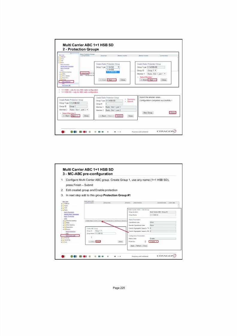
7/25/2019 Handbook - FibeAir IP-20G Advanced Training Course T8.0 ver1.pdf
http://slidepdf.com/reader/full/handbook-fibeair-ip-20g-advanced-training-course-t80-ver1pdf 219/277

7/25/2019 Handbook - FibeAir IP-20G Advanced Training Course T8.0 ver1.pdf
http://slidepdf.com/reader/full/handbook-fibeair-ip-20g-advanced-training-course-t80-ver1pdf 220/277
Proprietary and Confidential
Multi Carrier ABC 1+1 HSB SD
4 - MC ABC Configuration Adding member
15
1. Add Protection Group #1 into ABC
Proprietary and Confidential
Copy to Mate
16
Configure first (Main) radio link (MRMC, Freq., Link ID)
1. Select first radio link for Primary radio location
2. Select Copy to mate source radio location (In this case 1st link)
3. Apply new setting
4. Click on the Copy to Mate button
Page 226

7/25/2019 Handbook - FibeAir IP-20G Advanced Training Course T8.0 ver1.pdf
http://slidepdf.com/reader/full/handbook-fibeair-ip-20g-advanced-training-course-t80-ver1pdf 221/277
Thank You
Page 227

7/25/2019 Handbook - FibeAir IP-20G Advanced Training Course T8.0 ver1.pdf
http://slidepdf.com/reader/full/handbook-fibeair-ip-20g-advanced-training-course-t80-ver1pdf 222/277
July 2015, ver5
Configuration Management &
Software Download
Ceragon Training Services
Proprietary and Confidential
Agenda
2
Backup and Restore
Software Download
RFU Software Installation
Unit Info
Page 229

7/25/2019 Handbook - FibeAir IP-20G Advanced Training Course T8.0 ver1.pdf
http://slidepdf.com/reader/full/handbook-fibeair-ip-20g-advanced-training-course-t80-ver1pdf 223/277

7/25/2019 Handbook - FibeAir IP-20G Advanced Training Course T8.0 ver1.pdf
http://slidepdf.com/reader/full/handbook-fibeair-ip-20g-advanced-training-course-t80-ver1pdf 224/277
Backup Process
Proprietary and Confidential
Backup Configuration File Idea
6
1. Install FTP server We recommend to use FileZilla Server (not Client)
2. Setup FileZilla Server parameters (Users, Shared Folders)
3. Synchronize Time via CLI
platform management time-services utc set date-and-time 30-01-2014,15:07:58
4. Setup communication parameters for IP20 unit with FTP Server
5. Create Configuration Backup inside IP20 unit
6. Export Configuration Backup to FTP server
Export
File
FTP IP address
Page 231

7/25/2019 Handbook - FibeAir IP-20G Advanced Training Course T8.0 ver1.pdf
http://slidepdf.com/reader/full/handbook-fibeair-ip-20g-advanced-training-course-t80-ver1pdf 225/277
Proprietary and Confidential
2. FTP Setup FileZilla Settings
7
1. Install FileZilla Server and Run it
2. Create User in FileZilla Server
Proprietary and Confidential
2. FTP Setup FileZilla Settings
8
3. Create shared folder in FTP Server PC (C:\ Backups)
4. Setup all permissions for this folder in FTP Server
5. Check Firewall settings in FTP Server PC and if port 21 is used only withFileZilla
FTP SERVER PC
FileZilla settings in FTP SERVER PC
Page 232
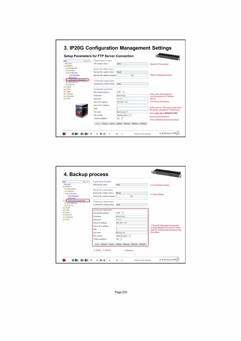
7/25/2019 Handbook - FibeAir IP-20G Advanced Training Course T8.0 ver1.pdf
http://slidepdf.com/reader/full/handbook-fibeair-ip-20g-advanced-training-course-t80-ver1pdf 226/277
Proprietary and Confidential
3. IP20G Configuration Management Settings
Setup Parameters for FTP Server Connection
Status for File transfer
User name and passwordmust be same as in FileZilla
Server
FTP Server IP address
Path in Server (This setup means that
file will be uploaded in C:\Backups)
Name.zip (.zip is MANDATORY)
Restore point selectionTime installation for future releases
Status for Backup creation
9
!!!
Proprietary and Confidential
4. Backup process
10
3. Backup
4. Check Status
5. Export
6. Check Export status
1. Setup Configuration parameters
included Restore Point which will beused for Configuration Backup inside
the system
2. Apply
Page 233

7/25/2019 Handbook - FibeAir IP-20G Advanced Training Course T8.0 ver1.pdf
http://slidepdf.com/reader/full/handbook-fibeair-ip-20g-advanced-training-course-t80-ver1pdf 227/277

7/25/2019 Handbook - FibeAir IP-20G Advanced Training Course T8.0 ver1.pdf
http://slidepdf.com/reader/full/handbook-fibeair-ip-20g-advanced-training-course-t80-ver1pdf 228/277
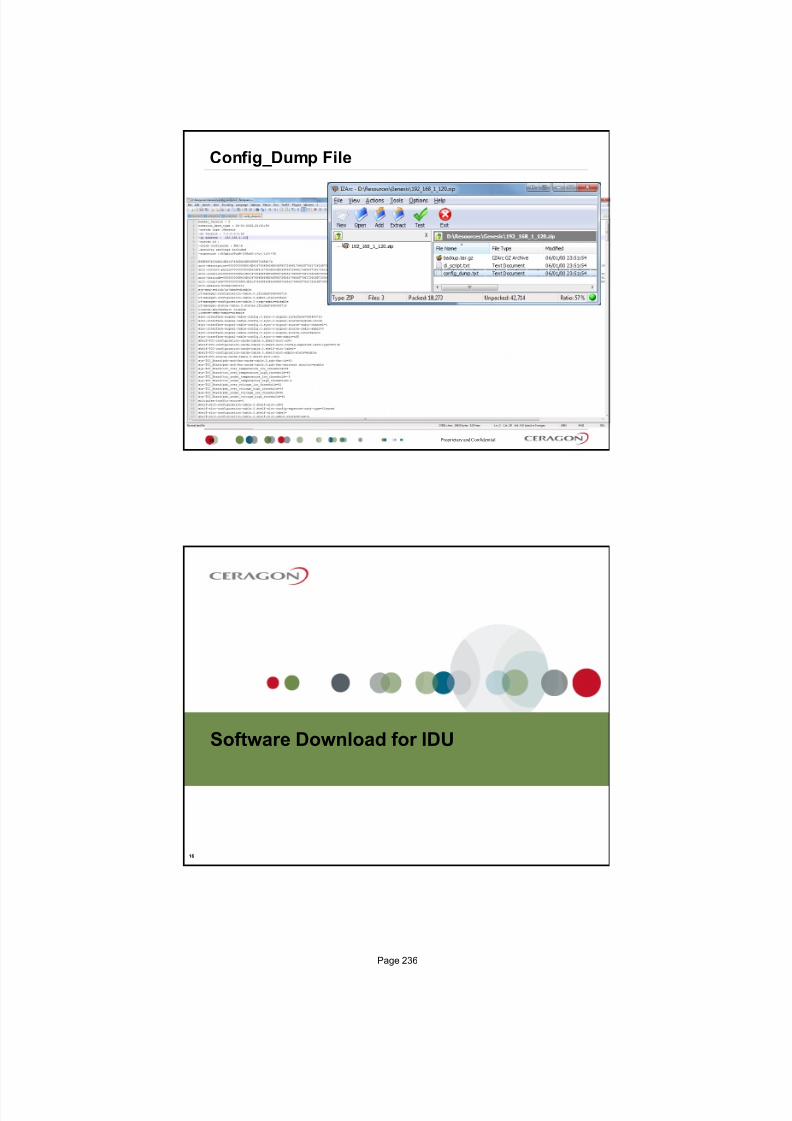
7/25/2019 Handbook - FibeAir IP-20G Advanced Training Course T8.0 ver1.pdf
http://slidepdf.com/reader/full/handbook-fibeair-ip-20g-advanced-training-course-t80-ver1pdf 229/277
Proprietary and Confidential
Config_Dump File
15
Software Download for IDU
16
Page 236

7/25/2019 Handbook - FibeAir IP-20G Advanced Training Course T8.0 ver1.pdf
http://slidepdf.com/reader/full/handbook-fibeair-ip-20g-advanced-training-course-t80-ver1pdf 230/277

7/25/2019 Handbook - FibeAir IP-20G Advanced Training Course T8.0 ver1.pdf
http://slidepdf.com/reader/full/handbook-fibeair-ip-20g-advanced-training-course-t80-ver1pdf 231/277
Proprietary and Confidential
Software process download
19
1. Setup Parameters
2. Apply
3. Download Software Files from FTP Server
4. Check Download Status
5. Install Downloaded Software
6. Check Installation Status
RFU Software Installation
20
Page 238

7/25/2019 Handbook - FibeAir IP-20G Advanced Training Course T8.0 ver1.pdf
http://slidepdf.com/reader/full/handbook-fibeair-ip-20g-advanced-training-course-t80-ver1pdf 232/277

7/25/2019 Handbook - FibeAir IP-20G Advanced Training Course T8.0 ver1.pdf
http://slidepdf.com/reader/full/handbook-fibeair-ip-20g-advanced-training-course-t80-ver1pdf 233/277
Unit Information file
23
Proprietary and Confidential
Unit Info
24
Status for File transfer
User name and password
must be same as in FileZillaServer
FTP Server IP address
Path in Server (This setup means that
file will be uploaded in C:\Backups)
Name.zip (.zip is MANDATORY)
Status for Unit info creation
!!!
Includes technical data about the unit and also backup f iles placed in restore points
This file can be forwarded to customer support, at their request, to help in analyzing issues
that may occur
Page 240

7/25/2019 Handbook - FibeAir IP-20G Advanced Training Course T8.0 ver1.pdf
http://slidepdf.com/reader/full/handbook-fibeair-ip-20g-advanced-training-course-t80-ver1pdf 234/277
Proprietary and Confidential
Create and Transfer process
25
3. Create
4. Check Status
5. Export
6. Check Export status
1. Setup Configurationparameters included Restore
Point which will be used for
Configuration Backup inside thesystem
2. Apply
Thank You
Page 241

7/25/2019 Handbook - FibeAir IP-20G Advanced Training Course T8.0 ver1.pdf
http://slidepdf.com/reader/full/handbook-fibeair-ip-20g-advanced-training-course-t80-ver1pdf 235/277

7/25/2019 Handbook - FibeAir IP-20G Advanced Training Course T8.0 ver1.pdf
http://slidepdf.com/reader/full/handbook-fibeair-ip-20g-advanced-training-course-t80-ver1pdf 236/277
Proprietary and ConfidentialProprietary and Confidential
3
Native TDM Services
3
IP-20G provides integrated support for transportation of TDM (E1) serviceswith integrated E1 interfaces.
Two types of TDM services are supported using the same hardware:
Native TDM trails
TDM Pseudowire services (enabling interoperability with third party
packet/PW equipment)
IP-20G provides native TDM support, utilizing a cross-connect module to
support up to 512 TDM trails.
The IP-20G Web EMS provides a simple and easy-to-use GUI that enables
users to provision end-to-end TDM trails. The Services Provisioning GUI
includes the following trail-creation end points:
TDM interface
Radio interface
Proprietary and ConfidentialProprietary and Confidential
4
Hybrid Services Engine Ethernet + TDM
4
Hybrid
Radio
Packettraffic
TDMtraffic
TDM cross-connect (VCs)
Network processor (EVCs)
GE/FE
E1
Ch-STM1
Native TDM Services (VCs)
Ethernet Services (EVCs)
Ethernet switched (L2) services E-Line (PtP), E-LAN (MPtMP)
Ethernet port based (L1) services (smart pipe)
TDM Pseudowire services Unstructured (SAToP), Structured (CESoP)
TDMPW
Services engine
Page 244

7/25/2019 Handbook - FibeAir IP-20G Advanced Training Course T8.0 ver1.pdf
http://slidepdf.com/reader/full/handbook-fibeair-ip-20g-advanced-training-course-t80-ver1pdf 237/277
Proprietary and Confidential
Ethernet Services (EVCs)
HybridRadioPacket
traffic
TDM
traffic
Hybrid services example: Ethernet EVCs + Native TDM
5
PtP Service
SAP
SAPSNPSAPSAP
MPtMP Service
Port
Port
Port
User Port
(UNI)
User Port
(UNI)
GE/FE
GE/FE
E1/DS1
TDM cross-connect (VCs)
Port
Network
Port
GE/FE
SNP
SNP
SAP
SAP
Proprietary and Confidential
PacketRadio
Port
Port Port
All-packet services example: Ethernet EVCs + TDM Pseudowire
6
Port
PtP Service
User Port
(UNI)
User Port
(UNI)Network
Port
GE/FE
SAPSNPSAPSAP
SAPSNPSAPSAP
SNP
SNP
SAP
SAP
PtP Service
MPtMP Service
S-VLAN =
200Packettraffic
GE/FE
GE/FE
E1/DS1
Ethernet Services (EVCs)
TDMPW
Page 245

7/25/2019 Handbook - FibeAir IP-20G Advanced Training Course T8.0 ver1.pdf
http://slidepdf.com/reader/full/handbook-fibeair-ip-20g-advanced-training-course-t80-ver1pdf 238/277
How to Setup Native TDM
7
Proprietary and Confidential
ETSI and ANSI
8
For IP-20G default standard is ETSI
To change the TDM interfaces to operate according to the ANSI (FCC) standard
(DS1), results in system reset and restores the default configuration.
Page 246

7/25/2019 Handbook - FibeAir IP-20G Advanced Training Course T8.0 ver1.pdf
http://slidepdf.com/reader/full/handbook-fibeair-ip-20g-advanced-training-course-t80-ver1pdf 239/277
Proprietary and Confidential
Native TDM Configuration
9
E1#1-16
VC‐1 VC
‐2 VC
‐3 VC
‐4
VC‐5 VC‐6 VC‐7 VC‐8
VC‐9 VC‐10 VC‐11 VC‐12
VC‐13 VC‐14 VC‐15 VC‐n
9
TDM
Network
Loop Timing
Proprietary and ConfidentialProprietary and Confidential
10
TDM Service Configuration 1
10
As first we have to create any Eth. service for Radio port, because we need specifywhich type of traffic will be carry by Radio.
Create any service point which is connected to the radio port in Ethernet/Services
Page 247
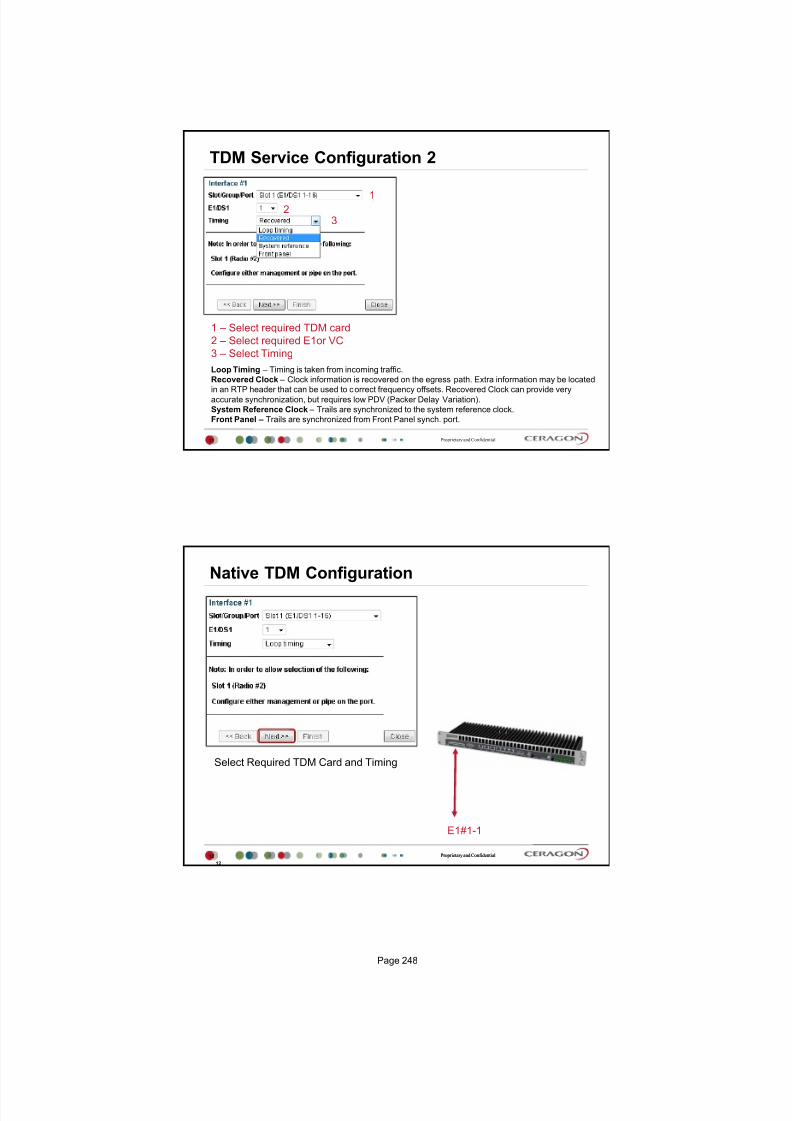
7/25/2019 Handbook - FibeAir IP-20G Advanced Training Course T8.0 ver1.pdf
http://slidepdf.com/reader/full/handbook-fibeair-ip-20g-advanced-training-course-t80-ver1pdf 240/277
Proprietary and Confidential
TDM Service Configuration 2
11
1
23
1 Select required TDM card
2 Select required E1or VC
3 Select Timing
Loop Timing Timing is taken from incoming traffic.
Recovered Clock Clock information is recovered on the egress path. Extra information may be located
in an RTP header that can be used to correct frequency offsets. Recovered Clock can provide very
accurate synchronization, but requires low PDV (Packer Delay Variation).
System Reference Clock Trails are synchronized to the system reference clock.
Front Panel Trails are synchronized from Front Panel synch. port.
Proprietary and ConfidentialProprietary and Confidential
12
Native TDM Configuration
12
Select Required TDM Card and Timing
E1#1-1
Page 248

7/25/2019 Handbook - FibeAir IP-20G Advanced Training Course T8.0 ver1.pdf
http://slidepdf.com/reader/full/handbook-fibeair-ip-20g-advanced-training-course-t80-ver1pdf 241/277

7/25/2019 Handbook - FibeAir IP-20G Advanced Training Course T8.0 ver1.pdf
http://slidepdf.com/reader/full/handbook-fibeair-ip-20g-advanced-training-course-t80-ver1pdf 242/277
Proprietary and Confidential
TDM Service Configuration
15
Selection Summary
TDM Path Protection
16
Page 250

7/25/2019 Handbook - FibeAir IP-20G Advanced Training Course T8.0 ver1.pdf
http://slidepdf.com/reader/full/handbook-fibeair-ip-20g-advanced-training-course-t80-ver1pdf 243/277
Proprietary and Confidential
TDM Path Protection
TDM path protection enables the operator to define two separate networkpaths for a single TDM service.
Two different kinds of path protection are available, each suitable for a
different network topology:
1:1 and 1+1 TDM path protection is suitable for ring networks that consist
entirely of IP-20N and/or IP-20G elements with two end-point interfaces for
the TDM trail.
1+1 Dual Homing TDM path protection is suitable for networks in which the
IP-20N and/or IP-20G elements are set up as a chain connected to the third
party networks at two different sites.
The ring is closed on one side by the IP-20N and/or IP-20G elements,
and on the other by third party equipment supporting standard SNCP.
In this case, there are three end-point interfaces in the IP-20N and/orIP-20G section of the network.
17
Proprietary and Confidential
1:1 TDM Path Protection
18
1:1 TDM path protection enables the operator to define two separate network paths for a singleTDM trail.
Each trail has the same TDM interface end points, but traffic flows to the destination via different
paths.
Bandwidth is utilized only on the active path, f reeing up resources on the standby path.
For native TDM services TDM path protection is done by means of configuring active and backup
path at the TDM service end-points.
Active
Path
Backup
Path
Page 251

7/25/2019 Handbook - FibeAir IP-20G Advanced Training Course T8.0 ver1.pdf
http://slidepdf.com/reader/full/handbook-fibeair-ip-20g-advanced-training-course-t80-ver1pdf 244/277
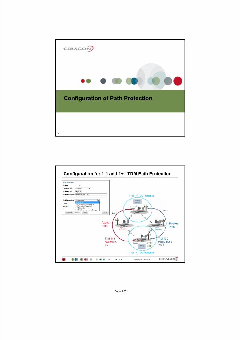
7/25/2019 Handbook - FibeAir IP-20G Advanced Training Course T8.0 ver1.pdf
http://slidepdf.com/reader/full/handbook-fibeair-ip-20g-advanced-training-course-t80-ver1pdf 245/277

7/25/2019 Handbook - FibeAir IP-20G Advanced Training Course T8.0 ver1.pdf
http://slidepdf.com/reader/full/handbook-fibeair-ip-20g-advanced-training-course-t80-ver1pdf 246/277
Proprietary and Confidential
Configuration 1:1 or 1+1 TDM Path Protection
23
1 2
45 or
Trail ID 1
Radio Slot 1VC-1
Trail ID 2
Radio Slot 2VC-1
1:1 or 1+1 TDM Protection
1:1 or 1+1 TDM Protection
Active
PathBackup
Path
E1#1
Slot 1
BypassconfigurationBypassconfiguration
3
Proprietary and Confidential
TDM Service
24
Interface #1 Interface #2 Protection Interface
Page 254

7/25/2019 Handbook - FibeAir IP-20G Advanced Training Course T8.0 ver1.pdf
http://slidepdf.com/reader/full/handbook-fibeair-ip-20g-advanced-training-course-t80-ver1pdf 247/277

7/25/2019 Handbook - FibeAir IP-20G Advanced Training Course T8.0 ver1.pdf
http://slidepdf.com/reader/full/handbook-fibeair-ip-20g-advanced-training-course-t80-ver1pdf 248/277
July 2015, ver 4
Troubleshooting
Ceragon Training Services
Proprietary and Confidential
Agenda
2
Faults and Alarms
Performance monitoring
RMON statistic
Loopback
Page 273

7/25/2019 Handbook - FibeAir IP-20G Advanced Training Course T8.0 ver1.pdf
http://slidepdf.com/reader/full/handbook-fibeair-ip-20g-advanced-training-course-t80-ver1pdf 249/277
Faults and Alarms
Proprietary and Confidential
Faults
4
Current Alarms
Event Log
Page 274

7/25/2019 Handbook - FibeAir IP-20G Advanced Training Course T8.0 ver1.pdf
http://slidepdf.com/reader/full/handbook-fibeair-ip-20g-advanced-training-course-t80-ver1pdf 250/277

7/25/2019 Handbook - FibeAir IP-20G Advanced Training Course T8.0 ver1.pdf
http://slidepdf.com/reader/full/handbook-fibeair-ip-20g-advanced-training-course-t80-ver1pdf 251/277

7/25/2019 Handbook - FibeAir IP-20G Advanced Training Course T8.0 ver1.pdf
http://slidepdf.com/reader/full/handbook-fibeair-ip-20g-advanced-training-course-t80-ver1pdf 252/277
Proprietary and Confidential
MRMC actual status
9
Proprietary and Confidential
Signal Level
10
Page 277

7/25/2019 Handbook - FibeAir IP-20G Advanced Training Course T8.0 ver1.pdf
http://slidepdf.com/reader/full/handbook-fibeair-ip-20g-advanced-training-course-t80-ver1pdf 253/277
Proprietary and Confidential
MSE Mean Square Error
11
Proprietary and Confidential
MRMC
12
Page 278

7/25/2019 Handbook - FibeAir IP-20G Advanced Training Course T8.0 ver1.pdf
http://slidepdf.com/reader/full/handbook-fibeair-ip-20g-advanced-training-course-t80-ver1pdf 254/277
Proprietary and Confidential
Radio Thresholds
13
Displays a table of every radio threshold settings
Proprietary and Confidential
Radio Traffic Capacity/Throughput
14
The Capacity PM Table page displays Radio Ethernet Capacity in Mbps for either radio for 15 minutes or 24 hours intervals
Page 279

7/25/2019 Handbook - FibeAir IP-20G Advanced Training Course T8.0 ver1.pdf
http://slidepdf.com/reader/full/handbook-fibeair-ip-20g-advanced-training-course-t80-ver1pdf 255/277
Proprietary and Confidential
Radio Traffic - Utilization
15
The Throughput PM Table page displays Radio Ethernet Throughput in Mbps for either radio for 15 minutes or 24 hours intervals
Proprietary and Confidential
Radio Traffic - Frame error rate
16
The Frame error rate PM Table page displays Radio Frame error rate for either radio for 15 minutes or 24 hours intervals
Page 280

7/25/2019 Handbook - FibeAir IP-20G Advanced Training Course T8.0 ver1.pdf
http://slidepdf.com/reader/full/handbook-fibeair-ip-20g-advanced-training-course-t80-ver1pdf 256/277
Proprietary and Confidential
Header Compression counters
17
Performance Monitoring Ethernet Services
Page 281

7/25/2019 Handbook - FibeAir IP-20G Advanced Training Course T8.0 ver1.pdf
http://slidepdf.com/reader/full/handbook-fibeair-ip-20g-advanced-training-course-t80-ver1pdf 257/277
Proprietary and Confidential
ETH PM RMON
19
Proprietary and Confidential
PM RMON Special Registers
20
RMON register / Counter Description
Undersize frames received Frames shorter than 64 bytes
Oversize frames received Frames longer than 2000 bytes
Jabber frames received Total frames received with a length of more than 2000 bytes,
but with an invalid FCS
Fragments frames received Total frames received with a length of less than 64
bytes, and an invalid FCS
Rx error frames received Total frames received with Phy‐error
FCS frames received Total frames received with CRC error, not countered in
"Fragments", "Jabber" or "Rx error" counters
Pause frames received Number of flow‐control pause frames received
Page 282
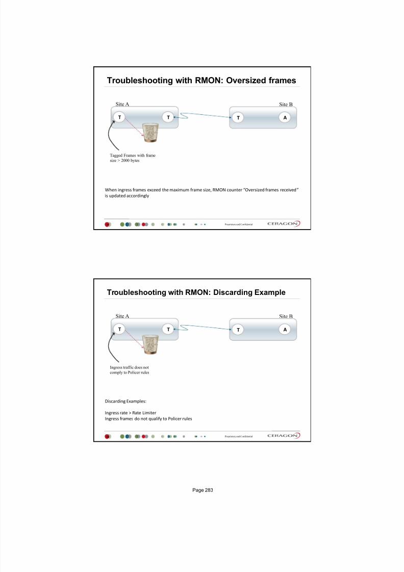
7/25/2019 Handbook - FibeAir IP-20G Advanced Training Course T8.0 ver1.pdf
http://slidepdf.com/reader/full/handbook-fibeair-ip-20g-advanced-training-course-t80-ver1pdf 258/277
Proprietary and Confidential
Troubleshooting with RMON: Oversized frames
21
When ingress frames exceed the maximum frame size, RMON counter Oversized frames received
is updated accordingly
Tagged Frames with frame
size > 2000 bytes
T AT T
Site BSite A
Proprietary and Confidential
Troubleshooting with RMON: Discarding Example
22
Discarding Examples:
Ingress rate > Rate Limiter
Ingress frames do not qualify to Policer rules
Ingress traffic does not
comply to Policer rules
T AT T
Site BSite A
Page 283

7/25/2019 Handbook - FibeAir IP-20G Advanced Training Course T8.0 ver1.pdf
http://slidepdf.com/reader/full/handbook-fibeair-ip-20g-advanced-training-course-t80-ver1pdf 259/277
Proprietary and Confidential
Troubleshooting with RMON: Monitoring specific
traffic types
23
Video streams are generally transmitted over UDP
with multicast addresses
To monitor traffic, check out the Multicast Frames
Received register
To limit MC traffic, assign a Policer with a MC CIR
rules
T T
Site BSite A
Monitor
Rate Limiter
Proprietary and Confidential
Ethernet TX / RX PM - Enabling
24
Enable Tx / RX Performance collection for specific Ethernet / Radio Port
It will enable TX and RX Performance collection
Page 284

7/25/2019 Handbook - FibeAir IP-20G Advanced Training Course T8.0 ver1.pdf
http://slidepdf.com/reader/full/handbook-fibeair-ip-20g-advanced-training-course-t80-ver1pdf 260/277
Proprietary and Confidential
Ethernet TX / RX PM
25
Performance based on 15 min and 24 hours
Proprietary and Confidential
Ethernet TX / RX PM View / Threshold window
26
Page 285

7/25/2019 Handbook - FibeAir IP-20G Advanced Training Course T8.0 ver1.pdf
http://slidepdf.com/reader/full/handbook-fibeair-ip-20g-advanced-training-course-t80-ver1pdf 261/277
Performance Monitoring TDM Services
Proprietary and Confidential
TDM Line Alarms
28
An example: Line alarms number 1040 = ( 10000010000 ) = 1024 + 16
It means that 1024 is Transceiver Loss of Multi-frame and 16 is Transceiver AIS alarm
Page 286

7/25/2019 Handbook - FibeAir IP-20G Advanced Training Course T8.0 ver1.pdf
http://slidepdf.com/reader/full/handbook-fibeair-ip-20g-advanced-training-course-t80-ver1pdf 262/277
Proprietary and Confidential
TDM port PMs Table
29
Loopbacks
Page 287

7/25/2019 Handbook - FibeAir IP-20G Advanced Training Course T8.0 ver1.pdf
http://slidepdf.com/reader/full/handbook-fibeair-ip-20g-advanced-training-course-t80-ver1pdf 263/277
Proprietary and Confidential
RFU RF Loopback
31
RFU RF LB
IF LB
Proprietary and Confidential
TDM Loopback
32
Page 288

7/25/2019 Handbook - FibeAir IP-20G Advanced Training Course T8.0 ver1.pdf
http://slidepdf.com/reader/full/handbook-fibeair-ip-20g-advanced-training-course-t80-ver1pdf 264/277
Proprietary and Confidential
Ethernet Loopback
33
Select port and click to Loopback button
Proprietary and Confidential
Ethernet Loopback Setting
34
Enable Swapping MAC addresses
Enable admin status
Page 289

7/25/2019 Handbook - FibeAir IP-20G Advanced Training Course T8.0 ver1.pdf
http://slidepdf.com/reader/full/handbook-fibeair-ip-20g-advanced-training-course-t80-ver1pdf 265/277
Thank You
Page 290

7/25/2019 Handbook - FibeAir IP-20G Advanced Training Course T8.0 ver1.pdf
http://slidepdf.com/reader/full/handbook-fibeair-ip-20g-advanced-training-course-t80-ver1pdf 266/277
Version 1
Synchronous Ethernet
December 2014
Proprietary and Confidential
Agenda
2
Synchronization in General
Jitter
Synchronization Effect
Concept of Synchronization in IP-20
Implementation
T3 Input & T4 output
SSM and ESMC
Sync E Clocks types
Synchronization modes of operation
Synchronization example
IP-20G Synchronization Settings
Page 333

7/25/2019 Handbook - FibeAir IP-20G Advanced Training Course T8.0 ver1.pdf
http://slidepdf.com/reader/full/handbook-fibeair-ip-20g-advanced-training-course-t80-ver1pdf 267/277
Version 1
Cascading port
December 2014
Proprietary and Confidential
Agenda
2
Hybrid TDM + Eth Concept
Configuration of Cascading port
Page 363

7/25/2019 Handbook - FibeAir IP-20G Advanced Training Course T8.0 ver1.pdf
http://slidepdf.com/reader/full/handbook-fibeair-ip-20g-advanced-training-course-t80-ver1pdf 268/277
Proprietary and Confidential
Hybrid (TDM + Eth) services over IP-20N cascading port
3
Cascading interfaces can be configured on ports 3 and 4 of an Ethernet LIC.
When operating in cascading mode, these interfaces can handle hybridEthernet and Native TDM traffic, enabling operators to create links among
multiple IP-20 units in a node for multi-directional applications based on hybrid
Ethernet and Native or Pseudowire TDM services
Proprietary and Confidential
Configuration 1st Auto negotiation - OFF
4
Cascading ports
Page 364

7/25/2019 Handbook - FibeAir IP-20G Advanced Training Course T8.0 ver1.pdf
http://slidepdf.com/reader/full/handbook-fibeair-ip-20g-advanced-training-course-t80-ver1pdf 269/277
Proprietary and Confidential
Configuration 2nd Cascading Port Configuration
5
Cascading ports
Proprietary and Confidential
Configuration 3rd Configure service
6
Create service point for Cascading Interface
Management or Pipe service point
Page 365

7/25/2019 Handbook - FibeAir IP-20G Advanced Training Course T8.0 ver1.pdf
http://slidepdf.com/reader/full/handbook-fibeair-ip-20g-advanced-training-course-t80-ver1pdf 270/277
Proprietary and Confidential
Configuration 4th Configure TDM Trail
7
Configure required TDM Trail by using cascading port
Proprietary and Confidential
Configuration 5th Configure Ethernet Service
8
Configure Ethernet Service where Cascading port will be one Service point with
specific Interface type and C & S-VLAN encapsulation
Page 366

7/25/2019 Handbook - FibeAir IP-20G Advanced Training Course T8.0 ver1.pdf
http://slidepdf.com/reader/full/handbook-fibeair-ip-20g-advanced-training-course-t80-ver1pdf 271/277
Thank You
Page 367

7/25/2019 Handbook - FibeAir IP-20G Advanced Training Course T8.0 ver1.pdf
http://slidepdf.com/reader/full/handbook-fibeair-ip-20g-advanced-training-course-t80-ver1pdf 272/277
Version 3
Link Aggregation (IEEE 802.3ad)
December 2014
Proprietary and Confidential
Agenda
2
Link Aggregation Introduction
LAG Advantages
LAG mechanism
Page 373

7/25/2019 Handbook - FibeAir IP-20G Advanced Training Course T8.0 ver1.pdf
http://slidepdf.com/reader/full/handbook-fibeair-ip-20g-advanced-training-course-t80-ver1pdf 273/277
Proprietary and Confidential
Introduction to Link Aggregation
3
IEEE Definition:
Link Aggregation allows one or more links to be aggregated
together to form a Link Aggregation Group, such that a MAC
Client can treat the Link Aggregation Group as if it were a
single link
The Link Aggregation Group is consisting of N parallelinstances of full duplex point-to-point links operating at the
same data rate
Traffic sent to the ports in such a group is distributed through aload balancing function
N
Proprietary and Confidential4
Link Aggregation Groups (LAG)Link aggregation (LAG) enables users to group several physical interfaces into
a single logical interface bound to a single MAC address. This logical interface
is known as a LAG group. Traffic sent to the interfaces in a LAG group is
distributed by means of a load balancing function. IP-20N uses a distribution
function of up to Layer 4 in order to generate the most efficient distribution
among the LAG physical ports, taking into account:
MAC DA and MAC SA
IP DA and IP SA
C-VLAN
S-VLAN
Layer 3 Protocol Field
UDP/TCP Source Port and Destination Port
MPLS Label
Page 374

7/25/2019 Handbook - FibeAir IP-20G Advanced Training Course T8.0 ver1.pdf
http://slidepdf.com/reader/full/handbook-fibeair-ip-20g-advanced-training-course-t80-ver1pdf 274/277
Proprietary and Confidential
LAG
5
LAG can be used to provide redundancy for Ethernet interfaces, both on the
same card (line protection) and on separate cards (line protection andequipment protection). LAGs can also be used to provide redundancy for radiolinks.
LAG can also be used to aggregate several interfaces in order to create a wider(aggregate) Ethernet link. For example, LAG can be used to create a 4 Gbpschannel.
Up to four LAG groups can be created.
LAG groups can include interfaces with the following constraints:
Only physical interfaces (including radio interfaces), not logical interfaces,can belong to a LAG group.
Interfaces can only be added to the LAG group if no services or servicepoints are attached to the interface.
Any classification rules defined for the interface are overridden by theclassification rules defined for the LAG group.
When removing an interface from a LAG group, the removed interface isassigned the default interface values.
IP-20N enables users to select the LAG members without limitations, such asinterface speed and interface type. Proper configuration of a LAG group is theresponsibility of the user.
Advantages
Page 375

7/25/2019 Handbook - FibeAir IP-20G Advanced Training Course T8.0 ver1.pdf
http://slidepdf.com/reader/full/handbook-fibeair-ip-20g-advanced-training-course-t80-ver1pdf 275/277
Proprietary and Confidential
1. Increased aggregate bandwidth
Link Aggregation allows the establishment of full duplex point-to-point links
that have a higher aggregate bandwidth than the individual links that form the
aggregation.
The capacity of the multiple links is combined into one logical link.
100 Mbps
Benefits of using Link Aggregation
7
Proprietary and Confidential
2. Improved Resiliency
In case of a failed link, remaining links take over utilization of new available BW
Traffic via LAG is distributed according to user s policy improved reliability
8
Benefits of using Link Aggregation
Page 376

7/25/2019 Handbook - FibeAir IP-20G Advanced Training Course T8.0 ver1.pdf
http://slidepdf.com/reader/full/handbook-fibeair-ip-20g-advanced-training-course-t80-ver1pdf 276/277
Proprietary and Confidential
3. Reduced Complexity & Administration
When multiple ports are allocated between two ETH switches, broadcast storms are
created due to physical loops. STP is required to eliminate loops by blocking the redundant
port.
When multiple ports are allocated between 2 Routers, Routing Protocols are required to
control traffic paths.
With LA STP or routing protocols are not needed, therefore, less processing is involved.
STP requires blocking and
path cost calculations
9
Benefits of using Link Aggregation
Proprietary and Confidential
4. Reduced Cost
Instead of utilizing an expensive GbE port(s) to transport 200Mbps
>> we trunk N x FE ports
10
Benefits of using Link Aggregation
Page 377

7/25/2019 Handbook - FibeAir IP-20G Advanced Training Course T8.0 ver1.pdf
http://slidepdf.com/reader/full/handbook-fibeair-ip-20g-advanced-training-course-t80-ver1pdf 277/277